evaluation of channel coding in ofdm systemsethesis.nitrkl.ac.in/25/1/nishar-ahmad.pdf ·...
TRANSCRIPT

Evaluation of Channel Coding in OFDM Systems
A THESIS SUBMITTED IN PARTIAL FULFILLMENT OF THE REQUIREMENTS FOR THE DEGREE OF
Master of Technology in ‘Telematics and Signal Processing’Master of Technology in ‘Telematics and Signal Processing’Master of Technology in ‘Telematics and Signal Processing’Master of Technology in ‘Telematics and Signal Processing’
ByByByBy
Nishar Ahamed Gugudu
Department of Electronics and Communication Engineering National Institute Of Technology, Rourkela
Rourkela-769008 Orissa
May-2006

CERTIFICATE
This is to certify that the work in this thesis entitled “Evaluation of Channel Coding in
OFDM Systems” by Nishar Ahamed Gugudu, has been carried out under my
supervision in partial fulfillment of the requirements for the degree of Master of
Technology in ‘Electronics and Communication Engineering’ during session 2005-
2006 in the Department of Electronics and Communication Engineering, National
Institute of Technology, Rourkela and this work has not been submitted elsewhere for a
degree.
Dr. S.K.Patra Asst.Professor, Dept. of ECE
National Institute of Technology, Rourkela
Place:
Dated:

Acknowledgements
With a deep sense of gratitude, I wish to express my sincere thanks to my guide,
Dr. S.K. Patra, Asst. Professor, Electronics and Communication Engineering
Deparatment for giving me the opportunity to work under him on this thesis. I truly
appreciate and value his esteemed guidance and encouragement from the beginning to the
end of this thesis. I am extremely grateful to him.His knowledge and company at the time
of crisis would be remembered lifelong.
I want to thank all my teachers Dr G. Panda, Dr G.S Rath, Dr K.K Mahapatra
and Dr S. Meher for providing a solid background for my studies and research
thereafter. They have been great sources of inspiration to me and I thank them from the
bottom of my heart.
I wish I would never forget the company I had from my fellow research scholars
of my department and my classmates. In particular, I am extremely thankful to Sunil,
Manas, Saroj and Sushant for sharing their knowledge and expertise. I would like to
thank my classmates Raghuveer, Vinod, Gyana, Subhansu, Pradeesh, Anjali,
Jagdeesh, Sharath, Srinivas and Ramesh from whom I learned a lot and whose
companionship I enjoyed so much during my stay at NIT, Rourkela.
I will be failing in my duty if I do not mention the laboratory staff and
administrative staff of this department for their timely help.
I also want to thank my parents, who taught me the value of hard work by their
own example. I would like to share this moment of happiness with my mother and sister.
They rendered me enormous support during the whole tenure of my stay in NIT
Rourkela.
Finally, I would like to thank all whose direct and indirect support helped me
completing my thesis in time.

NISHAR AHAMED GUGUDU
20407013, MTech (Telematics and Signal Processing)
ABSTRACT
Channel coding plays a very important role in OFDM systems performance.
The structure of OFDM systems makes channel coding more effective in confronting
fading channels. Sometimes Coded OFDM is known as COFDM. The role of channel
coding in conjunction with frequency and time interleaving is to provide a link between
bits transmitted on separated carriers of the signal spectrum, in such a way that the
information conveyed by faded carriers can be reconstructed in the receiver. Frequency
selectivity, currently known to be a disadvantage, is then turned into an advantage that
can be called frequency diversity. Using Channel State Information (CSI), channel
coding can yield some additional gain. Channel state information is frequency response
of the channel or signal to noise ratio in each carrier.
This thesis analyzes OFDM system and the effect of channel coding in reducing BER.
Along with this soft decoding and decoding with CSI is also studied. Besides,
performance of convolutional codes Turbo codes in OFDM systems is compared and
compared. Besides, we compare the performance of convolution and turbo codes in
OFDM systems. The results have been validated through simulations.
This thesis also presents Space-Frequency Coded OFDM system consisting of two
transmitters and a single receiver. Simple Alamouti space time code is used. An Mary
PSK modulation is used to modulate the symbols across an OFDM channel. We also
proposed a variation of the scheme which tries to spread additional symbols across time-
frequency attempting to increase the rate of transmission without changing the type of
modulation employed or increasing the bandwidth. A Rayleigh frequency selective slow
fading channel is assumed through out the analysis. SER performance of the above
systems is carried out with emphasis on the modulation scheme and number of carriers.
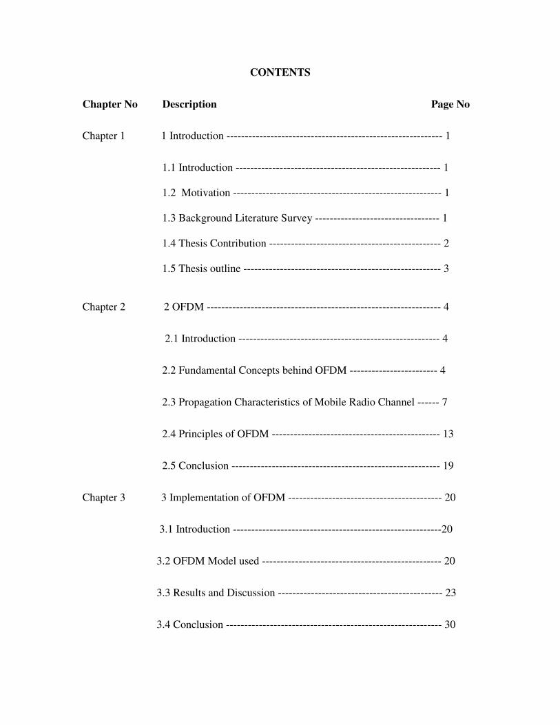
CONTENTS
Chapter No Description Page No
Chapter 1 1 Introduction ----------------------------------------------------------- 1
1.1 Introduction -------------------------------------------------------- 1
1.2 Motivation --------------------------------------------------------- 1
1.3 Background Literature Survey ---------------------------------- 1
1.4 Thesis Contribution ----------------------------------------------- 2
1.5 Thesis outline ------------------------------------------------------ 3
Chapter 2 2 OFDM ---------------------------------------------------------------- 4
2.1 Introduction ------------------------------------------------------- 4
2.2 Fundamental Concepts behind OFDM ------------------------ 4
2.3 Propagation Characteristics of Mobile Radio Channel ------ 7
2.4 Principles of OFDM ---------------------------------------------- 13
2.5 Conclusion --------------------------------------------------------- 19
Chapter 3 3 Implementation of OFDM ------------------------------------------ 20
3.1 Introduction ---------------------------------------------------------20
3.2 OFDM Model used ------------------------------------------------- 20
3.3 Results and Discussion --------------------------------------------- 23
3.4 Conclusion ----------------------------------------------------------- 30

Chapter 4 4 Channel Coding in OFDM ------------------------------------------ 31
4.1 Introduction ---------------------------------------------------------- 31
4.2 Different Coding Techniques ------------------------------------- 31
4.3 Burst Error Correction Techniques ------------------------------- 36
4.4 Simulation of an COFDM System -------------------------------- 44
4.5 Results and Discussions -------------------------------------------- 45
4.6 Conclusion ----------------------------------------------------------- 50
Chapter 5 5 Space Frequency Coded OFDM ------------------------------------- 51
5.1 Introduction ----------------------------------------------------------- 51
5.2 Space Frequency Coding Technique ------------------------------ 51
5.3 Overloaded OFDM -------------------------------------------------- 54
5.4 Results and Discussions --------------------------------------------- 55
5.5 Conclusion ------------------------------------------------------------ 56
Chapter 6 6 Conclusion --------------------------------------------------------------- 57
6.1 Introduction ------------------------------------------------------------ 57
6.2 Achievement of thesis ------------------------------------------------ 57
6.3 Limitation of work ---------------------------------------------------- 58
6.4 scope for further research --------------------------------------------- 58
References ---------------------------------------------------------------- 59

LIST OF FIGURES
Figure No Figure Title Page No
Fig 2.2.1 Frequeny Spectrum of an OFDM Transmission ------------------- 5
Fig 2.2.2 Carrier signals in an OFDM Transmission -------------------------- 5
Fig 2.2.3 A single carrier of OFDM --------------------------------------------- 6
Fig 2.3.1 A typical Rayleigh Fading Envelope -------------------------------- 9
Fig 2.3.2 Multipath Delay Spread ----------------------------------------------- 11
Fig 2.4.1 The Frequeny Selective Channel response and the relatively ----- 13
flat response on each subchannel
Fig 2.4.2 Block diagram of an OFDM System --------------------------------- 14
Fig 2.4.3 Multi Carrier Modulation using IDFT ------------------------------- 17
Fig 2.4.4 The transmitted symbols frame structure and the received ------- 18
symbols overlapping during the interference interval
Fig 2.4.5 IBI-two adjacent OFDM symbols interference and the ---------- 19
Cyclic prefix eliminating this interference
Fig 3.1 OFDM Model used for Simulations -------------------------------- 33
Fig 3.2 BER versus SNR for OFDM using BSPK, QPSK and 16PSK -- 36
Fig 3.3 Delay Spread tolerance of ODFM ---------------------------------- 37
Fig 3.4 Effect of peak power clipping for OFDM -------------------------- 38

Fig 3.5 Effect of frame synchronization error on the received OFDM ---- 39
signal
Fig 3.6 4 QAM constellation ---------------------------------------------------- 40
Fig 3.7 Received 4 QAM constellation ---------------------------------------- 40
Fig 3.8 Symbol error rate Vs SNR (in dB) ------------------------------------ 40
Fig 3.9 OFDM Constellation --------------------------------------------------- 41
Fig 3.10 OFDM Time Domain Signal ----------------------------------------- 41
Fig 3.11 Approximate OFDM spectrum --------------------------------------- 41
Fig 3.12 BPSK BER performance of OFDM in an AWGN channel ------ 42
Fig 3.13 OFDM performance in a fast flat Rayleigh faded channel ------ 42
Fig 4.1 Interleaving Block diagram -------------------------------------------- 50
Fig 4.2 Convolutional Coder ---------------------------------------------------- 53
Fig 4.3 Constraint length k=2 convolutional encoder ----------------------- 55
Fig 4.4 Recursive systematic convolutional encoder ----------------------- 55
Fig 4.5 Turbo encoding scheme ----------------------------------------------- 56
Fig 4.6 COFDM simulation Model ------------------------------------------- 57
Fig 4.7 BER Vs SNR for OFDM and SC in AWGN and Multipath ----- 58
Fig 4.8 BER with different guard intervals ----------------------------------- 58
Fig 4.9 OFDM and SC performance with and without coding ------------ 59

Fig 4.10 BER Vs SNR for CC –hard and soft ---------------------------------- 59
Fig 4.11 BER with and without interleaving ------------------------------------ 60
Fig 4.12 BER Vs SNR for with and without CSI ------------------------------ 60
Fig 4.13 BER Vs SNR for No coding, Hamming, RS, CC ------------------- 61
Fig 4.14 RS-CC block diagram --------------------------------------------------- 61
Fig 4.15 BER Vs SNR for CC and RS-CC -------------------------------------- 62
Fig 4.16 BER Vs SNR for Turbo and RS-Turbo coding ---------------------- 62
Fig 5.1 A Space Frequency OFDM system ------------------------------------ 65
Fig 5.2 SER Vs EbNo for 64 ary PSK ------------------------------------------- 69

LIST OF TABLES
Table No Table Title Page No
2.1 Typical attenuation in a radio channel ----------------------------- 9
2.2 Cumulative distribution for Rayleigh distribution --------------- 10
2.3 Delay spread in various environments ----------------------------- 12
2.4 OFDM system parameters used for simulations ------------------ 36
4.1 Possible sequences from a 4 bit word ------------------------------ 47
4.2 OFDM Simulation parameters used -------------------------------- 58

ABBREVIATIONS USED
OFDM ------------- Orthogonal Frequency Division Multiplexing
FDM ---------------- Frequency Division Multiplexing
RS coding------------ Reed Solomon coding
Wireless LAN--------wireless Local Area Network
DAB -------------------Digital Audio Broadcasting
DFT --------------------Discrete Fourier Transform
HDSL ------------------High bit-rate digital subscriber line
ADSL ------------------Asymmetric digital subscriber line
VDSL ------------------very high speed digital subscriber line
HDTV ------------------high definition television
SCM --------------------single carrier modulation
RECT pulse ------------Rectangular pulse
FFT ----------------------Fast Fourier Transform
QAM --------------------quadrature division multiplexing
UHF ----------------------Ultra high Frequencies
COFDM ------------------coded OFDM
CDMA ---------------------code division multiple access
TDMA --------------------time division multiple access

BPSK -------------------Binary phase shift keying
QPSK -------------------quadrature phase shift keying
IBI -----------------------Inter block interference
CP -----------------------cyclic prefix
FEC ---------------------forward error correction
RSC --------------------recursive convolutional encoder
WWAN ----------------wireless wide area network
SNR --------------------signal to noise ratio
SER ---------------------symbol error rate
BER ---------------------Bit Error rate

Evaluation of Channel coding in OFDM systems
NIT Rourkela 1
Chapter 1
INTRODUCTION
1.1 Introduction:
The telecommunications’ industry is in the midst of a veritable explosion in
wireless technologies. Once exclusively military, satellite and cellular technologies are
now commercially driven by ever more demanding consumers, who are ready for
seamless communication from their home to their car, to their office, or even for outdoor
activities. With this increased demand comes a growing need to transmit information
wirelessly, quickly and accurately. To address this need, communications engineer have
combined technologies suitable for high rate transmission with forward error correction
(FEC) techniques. This is particularly important as wireless communications channels are
far more hostile as opposed to wire alternatives, and the need for mobility proves
especially challenging for reliable communications.
1.2 Motivation:
For the most part, OFDM is the standard being used throughout the world to achieve the
high data rates necessary for data intensive applications that must now become routine.
Different coding schemes like Hamming coding, Reed Solomon (RS) coding,
Convolutional coding, Turbo coding have been studied and compared. A combination of
the coding schemes is also implemented and simulated like RS-Convolutional coding,
RS-Turbo coding.
At last Space Frequency coding is studied which performs well in a frequency selective
channel.
1.3 Background literature survey:
The concept of using parallel data transmission by means of frequency
division multiplexing (FDM) was published in mid 60’s [2]. Some early development
with this can be traced back to the 50s [1]. A U.S. patent was filled and issued in January

Evaluation of Channel coding in OFDM systems
NIT Rourkela 2
1970 [3]. The idea was to use parallel data streams and FDM with overlapping sub
channels to avoid the use of high-speed equalization and to combat impulsive noise, and
multipath distortion as well as to fully use the available bandwidth. The initial
applications were in the military communications. Weinstein and Ebert [5] applied the
discrete Fourier transform (DFT) to parallel data transmission system as part of the
modulation and demodulation process. In the 1980s, OFDM has been studied for high-
speed modems [6], digital mobile communications [8] and high-density recording [7].
Various fast modems were developed for telephone networks [12]. In 1990s, OFDM has
been exploited for wideband data communications over mobile radio FM channels [14],
wireless LAN [11] wireless multimedia communication [15], high-bit-rate digital
subscriber lines (HDSL) [16], asymmetric digital subscriber lines (ADSL) [9], very high-
speed digital subscriber lines (VHDSL) [13], [17], digital audio broadcasting (DAB) [18]
and HDTV terrestrial broadcasting [10].
In a classical parallel data system, the total signal frequency band is divided into N
nonoverlapping frequency subchannels. Each subchannel is modulated with a separate
symbol and then the N subchannels are frequency-multiplexed. It seems good to avoid
spectral overlap of channels to eliminate interchannel interference. However, this leads to
inefficient use of the available spectrum. To cope with the inefficiency, the ideas
proposed from the mid-1960s were to use parallel data and FDM with overlapping
subchannels, in which, each carrying a signaling rate b is spaced b apart in frequency to
avoid the use of high-speed equalization and to combat impulsive noise and multipath
distortion, as well as to fully use the available bandwidth.
1.4 Thesis contribution:
OFDM has received increased attention due to its capability of supporting high-data-rate
communication in frequency selective fading environments which cause inter-symbol
interference (ISI) [18]. Instead of using a complicated equalizer as in the conventional
single carrier systems, the ISI in OFDM can be eliminated by adding a guard interval
which significantly simplifies the receiver structure. However, in order to take advantage
of the diversity provided by the multi-path fading, appropriate frequency interleaving and
coding is necessary. Therefore, coding becomes an inseparable part in most OFDM

Evaluation of Channel coding in OFDM systems
NIT Rourkela 3
applications and a considerable amount of research has focused on optimum encoder,
decoder, and interleaver design for information transmission via OFDM over fading
environments, e.g. [19]-[22].
Different coding schemes like Hamming coding, RS coding, Convolutional coding,
Turbo coding have been studied and compared. A combination of the coding schemes is
also implemented and simulated like RS-Convolutional coding, RS-Turbo coding.
At last Space Frequency coding is studied which performs well in a frequency selective
channel.
1.5 Thesis outline:
Following this introduction the remaining part of the thesis is organized as under;
Chapter 2 provides the fundamental concepts of OFDM and principles behind OFDM.
Propagation characteristics of mobile radio channels are also discussed along with
advantages and disadvantages of OFDM compared with single carrier modulation.
Chapter 3 provides discusses the implementation of OFDM that also discusses the
simulation model used here. Chapter 4 discusses the different coding techniques
implemented with OFDM. Chapter 5 discusses the Space Frequency coded OFDM and
its implementation. Chapter 6 summarizes the work undertaken in this thesis and points
to possible directions for future works.

Evaluation of Channel coding in OFDM systems
NIT Rourkela 4
Chapter 2
OFDM
2.1 Introduction
This thesis discusses about the evaluation of channel coding in OFDM systems. In order
to establish the context and need for the work undertaken, it is necessary to discuss the
fundamental concepts behind the work. This chapter brings out the need for channel
coding in OFDM systems. The chapter also discusses the propagation characteristics of a
mobile communication channel
This chapter is organized as follows. Following this introduction, section 2.2 discusses
Fundamental concepts behind OFDM, section 2.3 discusses the propagation
characteristics of a mobile communication channel, section 2.4 discusses about the
principles of OFDM Section 2.5 presents the advantages and disadvantages of OFDM
compared with single carrier scheme and finally section 2.8 provides the concluding
remarks.
2.2 Fundamental concepts behind OFDM:
2.2.1 What is Orthogonal Frequency Division Multiplexing?
OFDM is simply defined as a form of multi-carrier modulation where the carrier spacing
is carefully selected so that each sub carrier is orthogonal to the other sub carriers. Two
signals are orthogonal if their dot product is zero
That is, if you take two signals multiply them together and if their integral over an
interval is zero, then two signals are orthogonal in that interval. Orthogonality can be
achieved by carefully selecting carrier spacing, such as letting the carrier spacing be
equal to the reciprocal of the useful symbol period. As the sub carriers are orthogonal, the
spectrum of each carrier has a null at the center frequency of each of the other carriers in
the system. This results in no interference between the carriers, allowing them to be

Evaluation of Channel coding in OFDM systems
NIT Rourkela 5
spaced as close as theoretically possible. Mathematically, suppose we have a set of
signals Ψ , where Ψp is the p-th element in the set.
b ∫ψp(t) ψq
* (t) dt = k for p=q …………………..(1) .
a =0 for p ≠ q Where, Ψp and ψq are pth and qth elements in the set.
The signals are orthogonal if the integral value is zero. Interval [a, b] is a symbol period.
Since the carriers are orthogonal to each other the nulls of one carrier coincides with the
peak of another sub carrier. As a result it is possible to extract the sub carrier of interest
Figure: 2.2.1 Figure 2.2.2
OFDM transmits a large number of narrowband subchannels. The frequency range
between carriers is carefully chosen in order to make them orthogonal one another. In
fact, the carriers are separated by an interval of 1/T, where T represents the duration of an
OFDM symbol. The frequency spectrum of an OFDM transmission is illustrated in figure
2.2.1. Each sinc of the frequency spectrum in the Fig 2.2.1 corresponds to a sinusoidal
carrier modulated by a rectangular waveform representing the information symbol. One
could easily notice that the frequency spectrum of one carrier exhibits zero-crossing at
central frequencies corresponding to all other carriers. At these frequencies, the
intercarrier interference is eliminated, although the individual spectra of subcarriers
overlap. It is well known, orthogonal signals can be separated at the receiver by
correlation techniques [ ]. The receiver acts as a bank of demodulators, translating each
carrier down to baseband, the resulting signal then being integrated over a symbol period
to recover the data. If the other carriers all beat down to frequencies which, in the time
domain means an integer number of cycles per symbol period (T), then the integration
process results in a zero contribution from all these carriers. The waveform of some

Evaluation of Channel coding in OFDM systems
NIT Rourkela 6
carriers in a OFDM transmission is illustrated in Fig 2.2.2. The figure indicates the
spectrum of carriers significantly over laps over the other carrier. This is contrary to the
traditional FDM technique in which a guard band is provided between each carrier.
From the Figures illustrated, it is clear that OFDM is a highly efficient system and hence
is often regarded as the optimal version of multi-carrier transmission schemes. The
number of sub channels transmitted is fairly arbitrary with certain broad constraints, but
in practical systems, sub channels tend to be extremely numerous and close to each other.
For example the number of carriers in 802.11 wireless LAN is 48 while for Digital Video
Broadcast (DVB) it is as high as 6000 sub carriers. If we consider a single OFDM carrier,
we can model the transmitted pulse as a sinusoid multiplied by a RECT function. In the
frequency domain, the resulting spectrum has a x
sin(x) shape centered at the carrier
frequency as shown in the Figure 2.2.3.
Figure 2.2.3: A Single carrier of OFDM
It is worth mentioning here that relative to single carrier Modulation technique (SCM),
the OFDM carriers occupy a significant amount of bandwidth of the spectrum relative to
the symbol rate. This characteristic is not a problem given that the carriers overlap
significantly. The slow sin (x)/x roll off, which implies a wider carrier bandwidth is only
an issue at the edge of the channel spectrum. Standards like 802.11a, allow the RECT
Evaluation of Channel coding in OFDM systems
NIT Rourkela 7
pulse to be modified such that the rising and falling edges are softer (Raised cosine) at the
edge of their assigned spectrum. This helps constrain the spectrum without affecting data
transmissions OFDM offers several advantages over single carrier system like better
multipath effect immunity, simpler channel equalization and relaxed timing acquisition
constraints. But it is more susceptible to local frequency offset and radio front-end non-
linearities. The frequencies used in OFDM system are orthogonal. Neighboring
frequencies with overlapping spectrum can therefore be used. This results in efficient
usage of BW. The OFDM is therefore able to provide higher data rate for the same BW
introduced between the different carriers and in the frequency domain, which results in a
lowering of spectrum efficiency.
Moreover, to eliminate the banks of subcarrier oscillators and coherent demodulators
required by frequency-division multiplex, completely digital implementations could be
built around special-purpose hardware performing the fast Fourier transform (FFT),
which is an efficient implementation of the DFT. Recent advances in very-large-scale
integration (VLSI) technology make high-speed, large-size FFT chips commercially
affordable. Using this method, both transmitter and receiver are implemented using
efficient FFT techniques that reduce the number of operations from N2 in DFT down to N
log N. In the 1980s, OFDM was studied for high-speed modems, digital mobile
communications, and high-density recording. One of the systems realized the OFDM
techniques for multiplexed QAM using DFT and by using pilot tone, stabilizing carrier
and clock frequency control and implementing trellis coding are also implemented.
Moreover, various-speed modems were developed for telephone networks.
In the 1990s, OFDM was exploited for wideband data communications over mobile radio
FM channels [14], high-bit-rate digital subscriber lines (HDSL; 1.6 Mbps) [16],
asymmetric digital subscriber lines (ADSL; up to 6 Mbps) [9], very-high-speed digital
subscriber lines (VDSL; 100 Mbps) [17], digital audio broadcasting (DAB) [18], and
high-definition television (HDTV) terrestrial broadcasting [10].
2.3. Propagation Characteristics of mobile radio channel
In an ideal radio channel, the received signal would consist of only a single direct path
signal, which would provide perfect reconstruction of the transmitted signal at receiver.

Evaluation of Channel coding in OFDM systems
NIT Rourkela 8
However in a real channel, the signal is modified during transmission in the channel. The
received signal consists of a combination of attenuated, reflected, refracted, and
diffracted replicas of the transmitted signal. On top of all this, the channel adds noise to
the signal and can cause a shift in the carrier frequency if the transmitter or receiver is
moving and it is termed as Doppler Effect. Understanding of these effects on the signal is
important because the performance of a radio system is dependent on the radio channel
characteristics.
2.3.1 Attenuation:
Attenuation is the drop in the signal power when transmitting signal from one point to
another. It can be caused by the transmission path length, obstructions in the signal path,
and multipath effects. Any objects, which obstruct the line of sight signal from the
transmitter to the receiver, can cause attenuation. Shadowing of the signal can occur
whenever there is an obstruction between the transmitter and receiver. It is generally
caused by buildings and hills, and is the most important environmental attenuation factor.
Shadowing is most severe in heavily built up areas, due to the shadowing from buildings.
However, hills can cause a large problem due to the large shadow they produce. Radio
signals diffract off the boundaries of obstructions, thus preventing total shadowing of the
signals behind hills and buildings. However, the amount of diffraction is dependent on
the radio frequency used, with low frequencies diffracting more then high frequency
signals. Thus high frequency signals, especially, Ultra High Frequencies (UHF), and
microwave signals require line of sight for adequate signal strength. To over come the
problem of shadowing, transmitters are usually elevated as high as possible to minimize
the number of obstructions. Typical amounts of variation in attenuation due to shadowing
are shown in Table 2.1. Here typical attenuation due to shadowing in heavy built up
urban center, sub-urban area, open rural area and terrain irregularities are shown.
Shadowed areas tend to be large, resulting in the rate of change of the signal power
being slow. For this reason, it is termed slow-fading or log-normal shadowing.

Evaluation of Channel coding in OFDM systems
NIT Rourkela 9
Table 2.1 Typical Attenuation in a radio channel
Description Typical Attenuation due to Shadowing Heavy built-up urban center 20dB variation from street to street Sub-Urban area(fewer large buildings)
10dB greater signal power than built up urban center
Open rural area 20dB greater signal power than sub-urban areas Terrain irregularities and tree foliage 3-12dB signal power variation 2.3.2 Multipath Effects:
Rayleigh fading:
In a radio link, the RF signal from the transmitter may be reflected from objects such as
hills, buildings, or vehicles. This gives rise to multiple transmission paths at the receiver.
The relative phase of multiple reflected signals can cause constructive or destructive
interference at the receiver. This is experienced over very short distances (typically at
half wavelength distances), thus is given the term fast fading. These variations can vary
from 10-30dB over a short distance. Figure 2.3.1 shows the level of attenuation that can
occur due to the fading. Here the probability of signal level being less than the value
given is shown for different signal levels.
Fig: 2.3.1 A typical Rayleigh Fading Envelope

Evaluation of Channel coding in OFDM systems
NIT Rourkela 10
The Rayleigh distribution is commonly used to describe the statistical time varying nature
of the received signal power. It describes the probability of the signal level being
received due to fading. Table 2.2 shows the probability of the signal level for the
Rayleigh distribution
Table 2.2: Cumulative Distibution for Rayleigh distribution
Frequency Selective Fading:
In any radio transmission, the channel spectral response is not flat. It has dips or fades in
the response due to reflections causing cancellation of certain frequencies at the receiver.
Reflections off near-by objects (e.g. ground, buildings, trees, etc) can lead to multipath
signals of similar signal power as the direct signal. This can result in deep nulls in the
received signal power due to destructive interference.
For narrow bandwidth transmissions if the null in the frequency response occurs at the
transmission frequency then the entire signal can be lost. This can be partly overcome in
two ways.
By transmitting a wide bandwidth signal or spread spectrum as CDMA, any dips in the
spectrum only result in a small loss of signal power, rather than a complete loss. Another
method is to split the transmission up into many small bandwidth carriers, as is done in a
COFDM/OFDM transmission. The original signal is spread over a wide bandwidth thus,
any nulls in the spectrum are unlikely to occur at all of the carrier frequencies. This will
result in only some of the carriers being lost, rather then the entire signal. The
information in the lost carriers can be recovered provided enough FEC is sent.
Signal level
(dB about median)
% Probability of Signal Level
Being less than the value given
10 99
0 50
-10 5
-20 0.5
-30 0.05

Evaluation of Channel coding in OFDM systems
NIT Rourkela 11
2.3.3 Delay Spread:
The received radio signal from a transmitter consists of typically a direct signal, plus
reflections of object such as buildings, mountains and other structures. The reflected
signals arrive at a later time than the direct signal because of the extra path length, giving
rise to a slightly different arrival time of the transmitted pulse, thus spreading the
received energy. Delay spread is the time spread between the arrival of the first and last
multipath signal seen by the receiver.
In a digital system, the delay spread can lead to inter-symbol interference. This is due to
the delayed multipath signal overlapping with the following symbols. This can cause
significant errors in high bit rate systems, especially when using time division
multiplexing (TDMA). Figure 2.3.2 shows the effect of inter-symbol interference due to
delay spread on the received signal. As the transmitted bit rate is increased the amount of
intersymbol interference also increases. The effect starts to become very significant when
the delay spread is greater then ~50% of the bit time.
Fig 2.3.2 Multipath Delay Spread
Table 2.3 shows delay spread that can occur in various environments. The maximum
delay spread in an outdoor environment is approximately 20µsec, thus significant
intersymbol interference can occur at bit rates as low as 25kbps

Evaluation of Channel coding in OFDM systems
NIT Rourkela 12
Table 2.3: Delay Spread in various environments:
Inter-symbol interference can be minimized in several ways. One method is to reduce the
symbol rate by reducing the data rate for each channel (i.e. split the bandwidth into more
channels using frequency division multiplexing). Another is to use a coding scheme,
which is tolerant to intersymbol interference such as CDMA.
2.3.4. Doppler Shift:
When a wave source and a receiver are moving relative to one 1another the frequency of
the received signal will not be the same as the source. When they are moving toward each
other the frequency of the received signal is higher then the source, and when they are
approaching each other the frequency decreases. This is called the Doppler Effect. An
example of this is the change of pitch in a car’s horn as it approaches then passes by. This
effect becomes important when developing mobile radio systems.
The amount the frequency changes due to the Doppler Effect depends on the relative
motion between the source and receiver and on the speed of propagation of the wave. The
Doppler shift in frequency can be written:
∆f≈ ±f0v/c
Where, ∆f is the change in frequency of the source seen at the receiver,
fo is the frequency of the source,
v is the speed difference between the source and transmitter, and c is the speed of light.
For example: Let fo = 5.9 GHz, and v = 80km/hr = 22.22m/s (6.116 kms/hr aprox) then
the Doppler shift will be 437 Hz. This shift of 437Hz in the carrier will generally not
effect the transmission However, Doppler shift can cause significant problems if the
transmission technique is sensitive to carrier frequency offsets or the relative speed is
higher, which is the case for OFDM. If we consider now al link between to cars moving
Environment or Cause Delay Spread Maximum Path l
Length Difference
Indoor (room) 40nsec-200nsec 1 2m - 60m
Outdoor 1usec-20usec 300m-6km

Evaluation of Channel coding in OFDM systems
NIT Rourkela 13
in opposite directions, each one with a speed of 80 km/hr, the Doppler shift will be
double.
2.4 Principles of OFDM:
In a conventional serial data system, the symbols are transmitted sequentially, one by
one, with the frequency spectrum of each data symbol allowed to occupy the entire
available bandwidth. A high rate data transmission supposes a very short symbol
duration, conducing at a large spectrum of the modulation symbol. There are good
chances that the frequency selective channel response affects in a very distinctive manner
the different spectral components of the data symbol, hence introducing the ISI [23]. The
same phenomenon, regarded in the time domain consists in smearing and spreading of
information symbols such, the energy from one symbol interfering with the energy of the
next ones, in such a way that the received signal has a high probability of being
incorrectly interpreted. Intuitively, one can assume that the frequency selectivity of the
channel can be mitigated if, instead of transmitting a single high rate data stream, we
transmit the data
Simultaneously, on several narrow-band subchannels (with a different carrier
corresponding to each subchannel), on which the frequency response of the channel looks
“flat” (Reference Figure 2.4.1). Hence, for a given overall data rate, increasing the
number of carriers reduces the data rate that each individual carrier must convey,
therefore lengthening the symbol duration on each subcarrier. Slow data rate (and long
symbol duration) on each subchannel merely means that the effects of ISI are severely
reduced. This is in fact the basic idea that lies behind OFDM. Transmitting the data
among a large
Figure 2.5.1 The frequency-selective channel response and the relatively flat response on each subchannel

Evaluation of Channel coding in OFDM systems
NIT Rourkela 14
number of closely spaced subcarriers accounts for the “frequency division multiplexing”
part of the name. Unlike the classical frequency division multiplexing technique, OFDM
will provide much higher bandwidth efficiency. This is due to the fact that in OFDM the
spectra of individual subcarriers are allowed to overlap. In fact, the carriers are carefully
chosen to be orthogonal one another. As it is well known, the orthogonal signals do not
interfere, and they can be separated at the receiver by correlation techniques. The
orthogonality of the subcarriers accounts for the first part of the OFDM name.
The block diagram of an OFDM system:
In figure 2.5.2, a classical OFDM transmission scheme using FFT (Fast Fourier
Transform) is presented:
The input data sequence is baseband modulated, using a digital modulation scheme.
Various modulation schemes could be employed such as BPSK, QPSK (also with their
differential form) and QAM with several different signal constellations. There are also
forms of OFDM where a distinct modulation on each subchannel is performed (e.g.
transmitting more bits using an adequate modulation method on the carriers that are more
„confident”, like in ADSL systems). The modulation is performed on each parallel
substream, that is on the symbols belonging to adjacent DFT frames. The data symbols
are parallelized in N different substreams. Each substream will modulate a separate
carrier through the IFFT modulation block, which is in fact the key element of an OFDM
scheme, as we will see later. A cyclic prefix is inserted in order to eliminate the inter-

Evaluation of Channel coding in OFDM systems
NIT Rourkela 15
symbol and inter-block interference (IBI). This cyclic prefix of length L is a circular
extension of the IFFT-modulated symbol, obtained by copying the last L samples of the
symbol in front of it. The data are back-serial converted, forming an OFDM symbol that
will modulate a high-frequency carrier before its transmission through the channel. The
radio channel is generally referred as a linear time-variant system. To the receiver, the
inverse operations are performed: the data are down-converted to the baseband and the
cyclic prefix is removed. The coherent FFT demodulator will ideally retrieve the exact
form of transmitted symbols. The data are serial converted and the appropriated
demodulation scheme will be used to estimate the transmitted symbols.
In this section, the key points of OFDM are presented: the principles of a multicarrier
(parallel) transmission, the usage of FFT and the cyclic prefix.
2.4.1. The concept of multicarrier (parallel) transmission:
In a mobile radio environment, the signal is carried by a large number of paths with
different strength and delays. Such multipath dispersion of the signal is commonly
referred as, “channel-induced ISI” and yields the same kind of ISI distortion caused by an
electronic filter [24]. In fact, the multipath dispersion leads to an upper limitation of the
transmission rate in order to avoid the frequency selectivity of the channel or the need of
a complex adaptive equalization in the receiver. In order to mitigate the time-dispersive
nature of the channel, the finding of the multicarrier technique was to replace a single-
carrier serial transmission at a high data rate with a number of slower parallel data
streams. Each parallel stream will be then used to sequentially modulate a different
carrier. By creating N parallel substreams, we will be able to decrease the bandwidth of
the modulation symbol by the factor of N, or, in other words, the duration of a
modulation symbol is increased by the same factor. The summation of all of the
individual subchannel data rates will result in total desired symbol rate, with the drastic
reduction of the ISI distortion. The price to pay is of course very important, since the
multicarrier transmission seems to act as a frequency multiplexation, which will generate
problems in terms of bandwidth efficiency usage. The things go however better than
seemed, because in OFDM the carriers are orthogonal to each-other and they are
separated by a frequency interval of ∆f =1/T. The frequency spectrum of the adjacent

Evaluation of Channel coding in OFDM systems
NIT Rourkela 16
subchannels will overlap one another, but the carrier’s orthogonality will eliminate in
principle the interchannel interference that we feared of.
2.4.2 The Discrete Fourier Transform (DFT):
Though Multi carrier technique was introduced in the 1950 [1], the main reason that
hindered the OFDM expansion for a very long time was practical. As it seemed difficult
to generate such a signal, and even harder to receive and appropriately demodulate such a
signal. Also this technique required a very large array of sinusoidal generators and also a
large array of coherent demodulators to make it work. Therefore, the hardware solution
cant be practical. As a consequence of the explosive development of digital signal
processors (DSP), which can be used for generating and demodulating an OFDM signal,
the magic idea was to use Fast Fourier Transform (FFT), a modern DSP technique. FFT
merely represents a rapid mathematical method for computer applications of Discrete
Fourier Transform (DFT). The ability to generate and to demodulate the signal using a
software implementation of FFT algorithm is the key of OFDM current popularity. In
fact, the signal is generated using the Inverse Fast Fourier Transform (IFFT), the fast
implementation of Inverse Discrete Fourier Transform (IDFT). There is a mysterious
connection between this transform and the concept of multicarrier modulation. According
to its mathematical distribution, IDFT summarizes all sine and cosine waves of
amplitudes stored in X[k] array, forming a time domain signal:
x[n] = ∑−
=
1
0
].[N
k
kX ej.kп
N
2 n = ∑−
=
1
0
].[N
k
kX (cos (kп
N
2 n) + j.sin(
kп
N
2 n)), n=0,1,…,N-1 ( 2 )
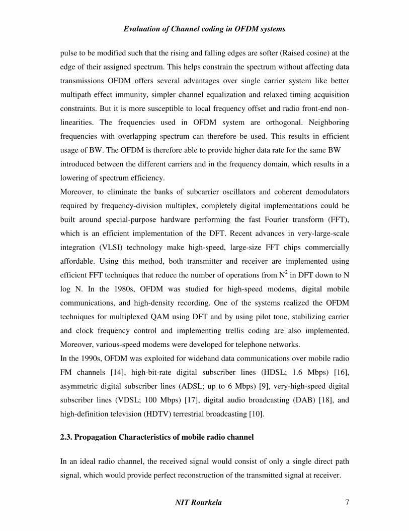
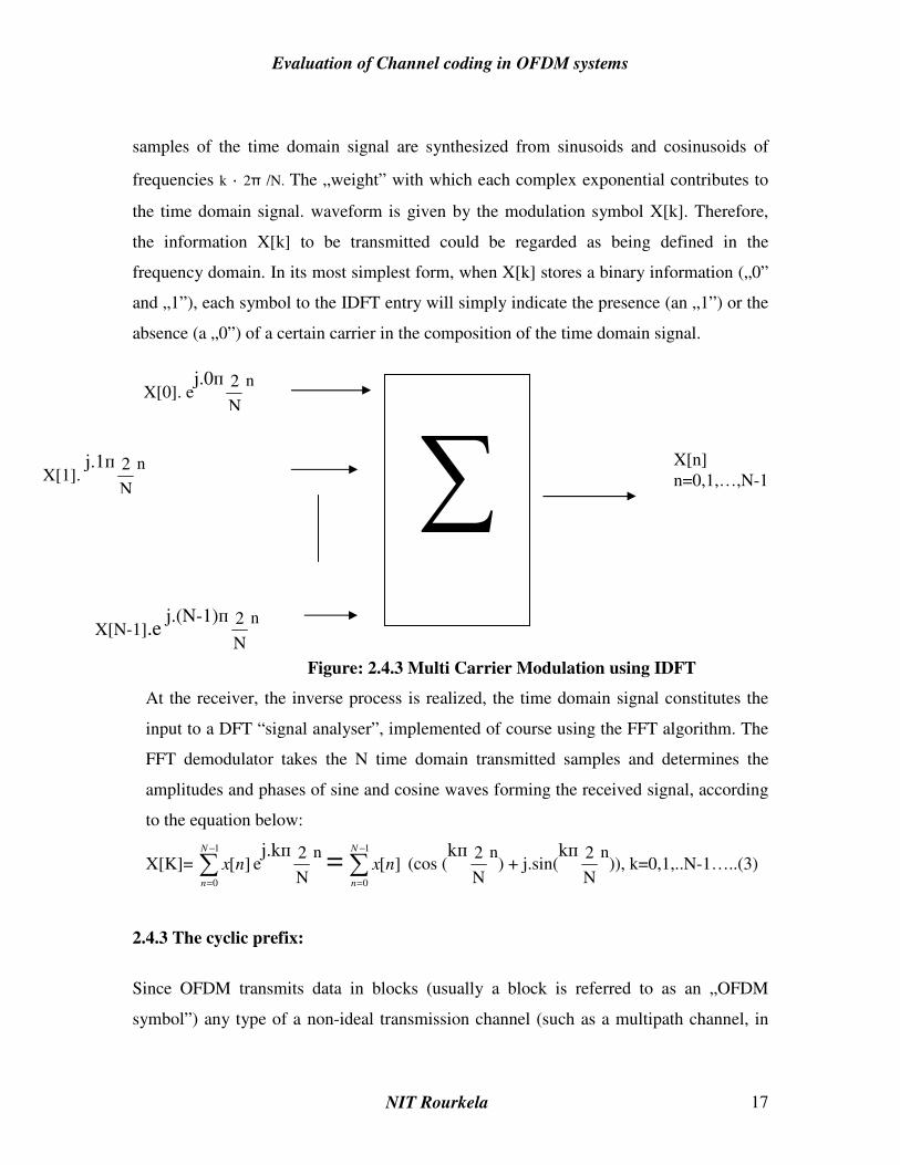
From (2), we can simply observe that IDFT takes a series of complex exponential
carriers, modulate each of them with a different symbol from the information array X[k],
and multiplexes all this to generate N samples of a time domain signal (Figure 2.5.3).
And what is really important, the complex exponential carriers are orthogonal to each
other, as we know from the Fourier decomposition. These carriers are frequency spaced
with ∆Ω = 2π/N. If we consider that the N data symbols X[k] come from sampling an
analog information with a frequency of fs, an easy to make discrete to analog frequency
conversion indicates a ∆f = 1/ T spacing between the subcarriers of the transmitted signal.
The schema presented in figure 6, relies on a classical signal synthesis algorithm. The N
Evaluation of Channel coding in OFDM systems
NIT Rourkela 17
samples of the time domain signal are synthesized from sinusoids and cosinusoids of
frequencies k · 2π /N. The „weight” with which each complex exponential contributes to
the time domain signal. waveform is given by the modulation symbol X[k]. Therefore,
the information X[k] to be transmitted could be regarded as being defined in the
frequency domain. In its most simplest form, when X[k] stores a binary information („0”
and „1”), each symbol to the IDFT entry will simply indicate the presence (an „1”) or the
absence (a „0”) of a certain carrier in the composition of the time domain signal.
Figure: 2.4.3 Multi Carrier Modulation using IDFT
At the receiver, the inverse process is realized, the time domain signal constitutes the
input to a DFT “signal analyser”, implemented of course using the FFT algorithm. The
FFT demodulator takes the N time domain transmitted samples and determines the
amplitudes and phases of sine and cosine waves forming the received signal, according
to the equation below:
X[K]= ∑−
=
1
0
][N
n
nx ej.kп
N
2 n = ∑−
=
1
0
][N
n
nx (cos (kп
N
2 n) + j.sin(
kп
N
2 n)), k=0,1,..N-1…..(3)
2.4.3 The cyclic prefix:
Since OFDM transmits data in blocks (usually a block is referred to as an „OFDM
symbol”) any type of a non-ideal transmission channel (such as a multipath channel, in
∑
X[n] n=0,1,…,N-1
X[0]. ej.0п
N
2 n
X[1]. j.1п
N
2 n
X[N-1].e j.(N-1)п
N
2 n

Evaluation of Channel coding in OFDM systems
NIT Rourkela 18
mobile communications system, or a classical dispersive channel as in wired
transmissions) will „spread” the OFDM symbol, causing the blocks of signal to interfere
one another. This type of interference is called Inter-Block Interference. IBI will
eventually lead to ISI, since two adjacent blocks will overlap, causing the distortion of
the symbol affected by overlapping (Figure 2.4.4).
Figure 2.4.4 The transmitted symbols frame structure and the received symbols are
Overlapping during the “interference interval”
In order to combat this interference, one of the possible approaches was to introduce „a
silence period” between the transmitted frames. Known as “zero prefix”, this silence
period consists in a number of zero samples, added to the front of each symbol. The
residual effect of the previous transmitted frame will affect only the „zero padding”
portion (if the channel is considered to be linear). These altered samples are discarded to
the receiver, and useful samples, unaffected by the IBI are used in order to demodulate
the signal. However, the zero-padding doesn’t seem the ideal solution, because the zero
prefix will destroy the periodicity of the carriers. The demodulation process that uses FFT
will be facilitated by keeping this periodicity, as we will see next.
Instead of this “quiet period” we could use a cyclic prefix (CP) at the beginning of each
symbol. The cyclic prefix consists of the last L samples of the OFDM symbol that are
copied in front of the data block [18]. If CP duration spans more than the channel impulse
response or than the multipath delay, the residual contribution from the previous block is
entirely absorbed by the cyclic prefix samples, that are thrown up to the receiver [18, 25,
26]. The same thing happened if a zero prefix is used, but the CP facilitates the receiver
carrier synchronization, since some signals instead of a long silence period are
Symbol i-1 Symbol i Symbol i+1
Non-ideal channel
i-1 i i+1

Evaluation of Channel coding in OFDM systems
NIT Rourkela 19
transmitted. Furthermore, using a circular extension maintains the carrier’s periodicity,
which is important in order to simplify the proper reconstruction of the signal using DFT.
The beneficent effect of the CP is illustrated in the figure 2.5.5. The transmitted OFDM
symbols are two cosinusoides, the second being phase shifted with 180o. If we consider a
radio channel, multipath attenuated replica of the first symbol will arrive to the receiver
with a certain delay. In figure 2.5.5 a) the delayed replica of the symbol i-1 will affect the
next received symbol for a duration marked with the “interference” label. If a cyclic
extension of duration Tg=T/4 is inserted in front of the useful data, the delayed replica of
the first symbol, will affect only the CP portion of the second symbol, that is actually
discarded to the receiver. If the guard
Fig: 2.5.5 IBI-two adjacent OFDM symbols interfere (a), the cyclic prefix eliminates
this interference (b)
2.5 Conclusion:
This chapter provides a brief introduction to different aspects dealt in this thesis. The
chapter discusses OFDM communication system in general and the propagation channel
characteristics of a mobile radio channel. Principles of OFDM are dealt in detail. These
concepts will be used in subsequent chapters of this thesis.

Evaluation of Channel coding in OFDM systems
NIT Rourkela 20
Chapter 3
IMPLEMENTATION OF OFDM
3.1 INTRODUCTION:
This chapter discusses the implementation and simulation of OFDM system in Matlab. In
order to know the performance of OFDM in AWGN and Frequency selective channels,
simulations are performed. We can study the performance of OFDM system under
different noise conditions and different environments. BER plots are plotted as the SNR
is varied. The chapter organizes as follows Section 3.2 discusses the OFDM model used
for simulation. Section 3.3 presents some simulation results with discussion
.
3.1 OFDM Model Used:
An OFDM system was modeled using Matlab (version 6.5) to allow various parameters
of the system to be varied and tested. The aim of doing the simulations was to measure
the performance of OFDM under different channel conditions, and to allow for different
OFDM configurations to be tested. Four main criteria were used to assess the
performance of the OFDM system. They are tolerance to multipath delay spread, peak
power clipping, channel noise and time synchronization errors. The OFDM system was
modeled using Matlab and is shown in Figure 3.1. A brief description of the model is
provided below.
Figure: 3.1 OFDM Model used for Simulations
Evaluation of Channel coding in OFDM systems
NIT Rourkela 21
3.1.1 Serial to Parallel Conversion:
The input serial data stream is formatted into the word size required for transmission, e.g.
2 bits/word for QPSK, and shifted into a parallel format. The data is then transmitted in
parallel by assigning each data word to one carrier in the transmission.
3.1.2 Modulation of Data:
The data to be transmitted on each carrier is then differential encoded with previous
symbols, then mapped into a Phase Shift Keying (PSK) format. Since differential
encoding requires an initial phase reference an extra symbol is added at the start for this
purpose. The data on each symbol is then mapped to a phase angle based on the
modulation method. For example, for QPSK the phase angles used are 0, 90, 180, and
270 degrees. The use of phase shift keying produces a constant amplitude signal and was
chosen for its simplicity and to reduce problems with amplitude fluctuations due to
fading.
3.1.3 Inverse Fourier Transform:
After the required spectrum is worked out, an inverse Fourier transform is used to find
the corresponding time waveform. The guard period is then added to the start of each
symbol.
3.1.4 Guard Period:
The guard period used was made up of two sections. Half of the guard period time is a
zero amplitude transmission. The other half of the guard period is a cyclic extension of
the symbol to be transmitted. This was to allow for symbol timing to be easily recovered
by envelope detection. However it was found that it was not required in any of the
simulations as the timing could be accurately determined position of the samples. After
the guard has been added, the symbols are then converted back to a serial time waveform.
This is then the base band signal for the OFDM transmission.

Evaluation of Channel coding in OFDM systems
NIT Rourkela 22
3.1.5 Channel:
A channel model is then applied to the transmitted signal. The model allows for the signal
to noise ratio, multipath, and peak power clipping to be controlled. The signal to noise
ratio is set by adding a known amount of white noise to the transmitted signal. Multipath
delay spread then added by simulating the delay spread using an FIR filter. The length of
the FIR filter represents the maximum delay spread, while the coefficient amplitude
represents the reflected signal magnitude.
3.1.6 Receiver:
The receiver basically does the reverse operation to the transmitter. The guard period is
removed. The FFT of each symbol is then taken to find the original transmitted spectrum.
The phase angle of each transmission carrier is then evaluated and converted back to the
data word by demodulating the received phase. The data words are then combined back
to the same word size as the original data.
3.1.7 OFDM simulation parameters:
Table 3.1 shows the configuration used for most of the simulations performed on the
OFDM signal. An 800-carrier system was used, as it would allow for up to 100 users if
each were allocated 8 carriers. The aim was that each user has multiple carriers so that if
several carriers are lost due to frequency selective fading that the remaining carriers till
allow the lost data to be recovered using forward error correction. For this reason any less
then 8 carriers per user would make this method unusable. Thus 400 carriers or less was
considered too small. However more carriers were not used due to the sensitivity of
OFDM to frequency stability errors. The greater the number of carriers a system uses, the
greater it required frequency stability. For most of the simulations the signals generated
were not scaled to any particular sample rate, thus can be considered to be frequency
normalized. Three carrier modulation methods were tested to compare their
performances. This was to show a trade off between system capacity and system
robustness. DBPSK gives 1 b/Hz spectral efficiency and is the most durable method,
however system capacity can be increased using DQPSK (2 b/Hz) and D16PSK (4 b/Hz)

Evaluation of Channel coding in OFDM systems
NIT Rourkela 23
but at the cost of a higher BER. The modulation method used is shown as BPSK, QPSK,
and 16PSK on all of the simulation plots, because the differential encoding was
considered to be an integral part of any OFDM transmission.
Table: 3.1 OFDM system parameters used for simulations
Parameter Value
Carrier Modulation used BPSK,QPSK,16PSK
FFT size 2048
Number of carrier used 800
Guard Time 512 samples (25%)
Guard Period Type Half zero signal, half a
cyclic extension of the symbol
3.3 Simualtion Results
Figure 3.2 BER versus SNR for OFDM using BSPK, QPSK and 16PSK
It was found that the SNR performance of OFDM is similar to a standard single carrier
digital transmission. This is to be expected, as the transmitted signal is similar to a
standard Frequency Division Multiplexing (FDM) system. Figure 3.2 shows the results
from the simulations. The results show that using QPSK the transmission can tolerate a
SNR of >10-12 dB. The bit error rate BER gets rapidly worse as the SNR drops below 6

Evaluation of Channel coding in OFDM systems
NIT Rourkela 24
dB. However, using BPSK allows the BER to be improved in a noisy channel, at the
expense of transmission data capacity. Using BPSK the OFDM transmission can tolerate
a SNR of >6-8 dB. In a low noise link, using 16PSK can increase the capacity. If the
SNR is >25 dB 16PSK can be used, doubling the data capacity compared with QPSK.
Figure 3.3 Delay Spread tolerance of ODFM
For this simulation the OFDM signal was tested with a multipath signal containing a
single reflected echo. The reflected signal was made 3 dB weaker then the direct signal as
weaker reflections then this did not cause measurable errors, especially for BPSK. Figure
3.3 shows the simulation results.
It can be seen from Figure 3.3 that the BER is very low for a delay spread of less then
approximately 256 samples. In a practical system (i.e. one with a 1.25 MHz bandwidth)
this delay spread would correspond to ~80 msec. This delay spread would be for a
reflection with 24 km extra path length. It is very unlikely that any reflection, which has
traveled an extra 24 km, would only be attenuated by 3 dB as used in the simulation, thus
these results show extreme multipath conditions. The guard period used for the
simulations consisted of 256 samples of zero amplitude, and 256 samples of a cyclic
extension of the symbol. The results show that the tolerable delay spread matches the
time of the cyclic extension of the guard period. It was verified that the tolerance is due to

Evaluation of Channel coding in OFDM systems
NIT Rourkela 25
the cyclic extension not the zeroed period with other simulations. These test however are
not shown to conserve space.
For a delay spread that is longer than the effective guard period, the BER rises rapidly
due to the inter-symbol interference. The maximum BER that will occur is when the
delay spread is very long (greater then the symbol time) as this will result in strong inter-
symbol interference. In a practical system the length of the guard period can be chosen
depending on the required multipath delay spread immunity required.
Figure 3.4 Effect of peak power clipping for OFDM
It was found that the transmitted OFDM signal could be heavily clipped with little effect
on the received BER. In fact, the signal could the clipped by up to 9 dB without a
significant increase in the BER. This means that the signal is highly resistant to clipping
distortions caused by the power amplifier used in transmitting the signal. It also means
that the signal can be purposely clipped by up to 6 dB so that the peak to RMS ratio can
be reduced allowing an increased transmitted power.

Evaluation of Channel coding in OFDM systems
NIT Rourkela 26
Figure 3.5 Effect of frame synchronization error on the received OFDM signal.
Figure 3.5 shows the effect of start time error on the received BER. This shows that the
starting time can have an error of up to 256 samples before there is any effect of the BER.
This length matches the cyclic extension period of the guard interval, and is due to the
guard period maintaining the orthogonality of the signal.
In any practical system, the timing error made be either early or late, thus any receiver
would aim for the middle of the expected starting time to allow for an error of ±128
samples. In addition, if the signal is subject to any multipath delay spread, this will
reduce the effective stable time of the guard period, thus reducing the starting time error
tolerance.
Simulation with 4-QAM
The OFDM system was simulated with the following parameters
Tu=224e-6; %useful OFDM symbol period
T=Tu/2048; %baseband elementary period
G=0; %choice of 1/4, 1/8, 1/15 and 1/32
delta=G*Tu; %guard band duration
Ts=Tu+delta; %total OFDM symbol period
Kmax=1705; %number of subcarriers
Kmin=0;

Evaluation of Channel coding in OFDM systems
NIT Rourkela 27
FS=4096; %IFFT/FFT length
q=10; %carrier period to elementary period ratio
fc=q*1/T; %carrier frequency
Rs=4*fc; %simulation period
t=0:1/Rs:Tu;
tt=0:T/2:Tu;
Repeat = 68; % one OFDM frame (68 OFDM symbols) is sent, symbol by symbol
SNR_dB = 0:2:16
The results obtained are shown in figures 3.6, 3.7 and 3.8
Figure 3.6 4 QAM constellation figure 3.7 received 4 QAM constellation
Figure 3.7 symbol error rate versus SNR (in dB)

Evaluation of Channel coding in OFDM systems
NIT Rourkela 28
Simulation with 64 QAM
Here the OFDM system was simulated with the following parameters.
N = 64; % number of carriers - 48 data, 4 pilot, 12 unused
L = 8; % oversampling factor
Symbols = 100; % number of OFDM symbols to simulate
Rate=1/2/4/8-------------BPSK/QPSK/16QAM/64QAM
The figures 3.8, 3.9, 3.10 represent the OFDM constellation for 64 carriers, OFDM time
domain signal and approximate OFDM spectrum
Figure 3.8 OFDM constellation Figure 3.9 OFDM time domain signal
Figure 3.10 approximate OFDM spectrum

Evaluation of Channel coding in OFDM systems
NIT Rourkela 29
Figure 3.11 BPSK BER performance of OFDM in an AWGN channel
Figure 3.12 OFDM performance in a fast flat Rayleigh faded channel

Evaluation of Channel coding in OFDM systems
NIT Rourkela 30
3.4 Conclusion
In this chapter the OFDM Modem was implemented in matlab and the performance was
evaluated for differet simulation parameters. Here three carrier modulation methods were
tested to compare their performances. This was to show a trade off between system
capacity and system robustness. The following points can be drawn from the study
presented in this chapter.
BPSK gives 1 b/Hz spectral efficiency and is the most durable method but system
capacity is less.
QPSK can be used to increase system capacity up to 2b/Hz but BER is more
compared to BPSK
16 PSK can increase the system capacity further up to 4b/Hz but here also BER is
compared to BPSK and QPSK.

Evaluation of Channel coding in OFDM systems
NIT Rourkela 31
Chapter 4
CHANNEL CODING IN OFDM
4.1 Introduction:
OFDM has recently received increased attention due to its capability of supporting high-
data-rate communication in frequency selective fading environments which cause inter-
symbol interference (ISI). Instead of using a complicated equalizer as in the conventional
single carrier systems, the ISI in OFDM can be eliminated by adding a guard interval
which significantly simplifies the receiver structure. However, in order to take advantage
of the diversity provided by the multi-path fading, appropriate frequency interleaving and
coding is necessary. Therefore, coding becomes an inseparable part in most OFDM
applications and a considerable amount of research has focused on optimum encoder,
decoder, and interleaver design for information transmission via OFDM over fading
environments.
This chapter discusses the performance of the OFDM with different coding techniques
and a combination of coding techniques. Following the introduction this chapter is
organized as under Section 4.2 describes the different coding techniques Section 4.3
describes about the burst error correction techniques. Section 4.4 provides concluding
remarks.
4.2 Different CODING Techniques:
FEC is widely used in digital telecommunications systems to make it easier to encode and
decode signals. Coding (FEC techniques) [27] introduces redundancy in data and adding
delay. Simplest error-detecting technique is parity check bit coding. i.e. adding an extra
binary digit at the end of each word. But it will be effective only if the probability of
error is very low.
Coding allows us to reduce the information bit error rate while maintaining
a fixed transmission rate. In principle it allows us to reach Shanon’s limit with ingenious
coding and enough unlimited complexity. The more commonly employed codes are:

Evaluation of Channel coding in OFDM systems
NIT Rourkela 32
1. Block Codes
1. Single Parity-Check Bit Code
2. Repeated Codes
3. Hadamard Code
4. Hamming Code
5. Extended Codes
6. Cyclic Codes
7. The Golay Code
8. BCH Codes
Block codes operate on a block of bits. Using a preset algorithm, we take a group of bits
and add a coded part to make a larger block. This block is checked at the receiver. The
receiver then makes a decision about the validity of the received sequence.
Block Codes . Block codes [27]are referred to as (n, k) codes. A block of k information bits are coded to
become a block of n bits.
n=k + r where r is the number of parity bits. k is the number of information
bits
Suppose a code word has the form
a1a2a3……………..akc1c2…………cr
Generation of a block code starts with a selection of the number r of the parity bits to be
added and thereafter with the specification of an H matrix.
h11 h12 ………. h1k 1 0 0 … 0
H= h21 h22 ………… h2k 0 1 0 … 0
………………. …………
hr1 hr2 ………… hrk 0 0 1 … 0
r*k r*r
h sub matrix Identity matrix, I
4.2.1 Single Parity-Check Bit Code:
It is an example of an block code [27]. Here parity check is selected to satisfy the
equation
a1+a2+…….ak+c1=0

Evaluation of Channel coding in OFDM systems
NIT Rourkela 33
h11 = h12 =……..= h1k =1
All other equations of the set are identically zero. Here r=1 and n=k+1.
This is a single error correcting code and will not correct errors.
4.2.2 Repeated Codes:
Here a binary 0 is encoded as a sequence of (2t+1) zeros, and a binary 1 as a similar
number of 1’s. Thus, k=1, r=2t, and n=2t+1.
For t=1, r=2 and n=3
4.2.3 Hadamard Code:
Code word in a Hadamard code [27] are the rows of a Hadamard matrix. The Hadamard
matrix is a square (n*n) matrix in which n=2k , k is number of bits in the uncoded word.
One code word consists of all zeros and all the other codewords have n/2, 0’s and n/2,
1’s. Further each codeword differs from another codeword in n/2 places and for this
reason the codewords are orthogonal to one another.
The Hadamard matrix which provides two codewords is
M2=
10
00
And the codewords are 00 and 01.
The matrix M4 which provides 4 code words is
M4=
*22
22
MM
MM=
0110
1100
1010
0000
The hamming distance of an orthogonal code is dmin=2
n=2k-1
Thus the number of errors that can be corrected with a Hadamard code is t=4
n-1
4.2.4 Hamming Code:
Hamming codes [28] are most widely used linear block codes. A Hamming code is
generally specified as (2n-1, 2n-n-1). The size of the block is equal to 2n-1. The number
of information bits in the block is equal to 2n-n-1 and the number of overhead bits is
equal to n. All Hamming codes are able to detect three errors and correct one. Common

Evaluation of Channel coding in OFDM systems
NIT Rourkela 34
sizes of Hamming codes are (7, 4), (15, 11) and (31, 26). All of these have the same
Hamming distance.Hamming code is a code in which dmin=3 so that t=1, i.e., a single error can
be corrected. n=2r-1; k=2r -1-r;
Lets take a look the (7, 4) Hamming code. In this code, the length of the information
sequence is 4 bits. So there are only 16 possible sequences. The table below lists all 16 of
these sequences.
Table 4.1- 16 possible sequences from a 4 bit word
Sequence
Number
i0 i1 i3 i4
1 0 0 0 1
2 0 0 1 0
3 0 0 1 1
4 0 1 0 0
5 0 1 0 1
6 0 1 1 0
7 0 1 1 1
8 1 0 0 0
9 1 0 0 1
10 1 0 1 0
11 1 0 1 1
12 1 1 0 0
13 1 1 0 0
14 1 1 0 1
15 1 1 1 1
16 0 0 0 0
.
H is called the parity matrix of the code. It has n rows and n-k columns. For a code of (7,
4), it has 7 rows and 3 columns. We can reorder the rows of this matrix any which way

Evaluation of Channel coding in OFDM systems
NIT Rourkela 35
we want. The only thing to keep in mind is that we want the basis rows to be together
either on top or at the bottom. Each reordering will give us a new Hamming code.
Following are just two ways we can order the rows of H, each of these will result in a
different code.
H =
100
010
001
011
101
110
111
a different ordering of H=
001
010
100
011
101
110
111
Now we take the upper part of this matrix (under the line) and create a new matrix called
G=
0111000
1010100
1100010
1110001
Take upper part of the H matrix (the one on the left) and add a unit matrix to the right of
it, making a new matrix of size (4 x 7). This is our generator matrix, the one that tells us
how the 16 info sequences will be mapped to the 16 valid codewords.
Rearrangement of the rows of H will lead to a different G matrix and hence will change
the mapping. The essential point to this is that two block codes of the same size may
create an entirely different mapping depending on how the rows are ordered, but each
mapping has the same Hamming weight and has the same error correction/detection
capability.Now all we have to do is multiply the information vector d with matrix G to
get a codeword c. c = d. G
For information sequence [0, 1, 1, 0], we get the following transmitted codeword of
length 7.
C= [0 1 1 0]
0111000
1010100
1100010
1110001
= [0 1 1 0 1 1 0]

Evaluation of Channel coding in OFDM systems
NIT Rourkela 36
4.2.5 Extended Codes:
All codes can be extended [27], that is, starting with a parity check matrix H, a new,
extended, matrix He(n+1, k) code.
He consists of the matrix with an added row consisting of all 1’s and an added right-hand
column consisting of all 0’s except for the bottommost elements which remains a 1.
Here, d emin=dmin+1;
4.2.6 Cyclic Codes:
They use generator polynomials to generate the code word [27].
4.2.7 Golay Code:
It is also an example of an cyclic code.
Golay code [27]is an (23,12) cyclic code whose generating function is
g(x)=x11+x9 +x7 +x6 +x5 +x+1
Its extended form is (24,12) code. With dmin=7 and dmin=8 for extended.
4.2.8 BCH Codes:
BCH code [27] employs k information bits, r parity check bits and therefore number of
bits in a codeword is n=k+r. Furthermore, the number of errors which can be corrected in
an n-bit code word is t=r/m;
Where m is an integer related to n as n=2m -1.
4.3 Burst Error Correction Techniques
The parity bits added in the block codes will correct a limited number of bit errors in each
codeword. When the bit errors are closely clustered we say that the errors occur in bursts.

Evaluation of Channel coding in OFDM systems
NIT Rourkela 37
4.3.1 Block Interleaving
A primary technique which is effective in overcoming error bursts is interleaving. The
principle of interleaving [27] is illustrated in Figure 4.1:
Figure 4.1 Interleaving block diagram
Before the data stream is applied to the channel, the data goes through a process of
interleaving and error correction coding. At the receiving end, the data is decoded i.e., the
data bits are evaluated in manner to take advantage of error correcting and detecting
features which result from the coding and the process of interleaving is undone.
L bits/row
kl inf bits a11 a12 ………….. a1l k bits/column
a21 a22 ……………. a2l
…………………………
ak1 ak2 ……………. akl
c11 c12 ……………. c1l
c21 c22 ……………. c2l r parity bits/column
……………………………
cr1 cr2 ……………. crl
As in above Figure a group of kl bits is loaded into a shift register which is organized into
k rows with l bits per row. The data stream is entered into the storage element at a11. At
each shift each bit moves one position to the right while the bit in the rightmost storage
element moves to the leftmost stage of the next row. Thus for example as indicated by the
arrow the content of a11 moves to a21. When kl bits have been entered the register is full
Interleaver and Coding
Decoding and Deinterleaver
Data Recovered data red
Evaluation of Channel coding in OFDM systems
NIT Rourkela 38
the first bit being in akl and the last bit in . At this point the data stream is diverted to a
second similar shift register and a process of coding is apple to the data held stored in the
first register. Here the information bits in a column (ex a11 a12 ………….. a1l ) are viewed as
the bits of an uncoded part to which parity bits are to be added. Thus the codeword a11 a12
………….. a1l c11 c12 ……………. c1l is formed, thereby generating a codeword with k
information bits and r parity bits.
When the coding is completed, the entire content of the k*l information
register as well as the r*l parity bits are transmitted over the channel. Generally the bit by
bit serial transmission is carried out row by row in the order
crl……. cr1. ……. c1l……. c11 akl …. .ak1 ………a12 a11
The received data is again stored in the same order as in the transmitter and error
correction decoding is performed. The parity bits are discarded and the data bits are
shifted out of the register.
4.3.2 Reed-Solomon (RS) CODE:
The RS block code [27] is organized on the basis of groups of bits. Such groups of bits
are referred to as symbols. We store sequences of m individual bits which appear serially
in a bit stream and thereafter operate with the m-bit sequence rather than individual bits.
These are called m-bit symbols. Even if an error occurs in a single bit of an symbol, the
entire symbol is in error. RS code has k information symbols, r parity symbols and a total
codeword length of n (=k+r) symbols. The number of symbols in the codeword is
arranged to be n=2m -1. The RS code is able to correct errors in t symbols where t=r/2.
4.3.3 Convolutional Coding:
Convolutional codes [29] are referred to as continuous codes as they operate on a certain
number of bits continuously. Interleaving has mitigating properties for fading channels
and works well in conjunction with these two types of coding.

Evaluation of Channel coding in OFDM systems
NIT Rourkela 39
Coding and decoding with Convolutional Codes
Convolutional codes are commonly specified by three parameters; (n,k,m).
n = number of output bits
k = number of input bits
m = number of memory registers
The quantity k/n called the code rate, is a measure of the efficiency of the code. Commonly k and
n parameters range from 1 to 8, m from 2 to 10 and the code rate from 1/8 to 7/8 except for deep
space applications where code rates as low as 1/100 or even longer have been employed.
Often the manufacturers of convolutional code chips specify the code by parameters (n,k,L), The
quantity L is called the constraint length of the code and is defined by
Constraint Length, L = k (m-1)
The constraint length L represents the number of bits in the encoder memory that affect the
generation of the n output bits. The constraint length L is also referred to by the capital letter K,
which can be confusing with the lower case k, which represents the number of input bits. In some
books K is defined as equal to product the of k and m. Often in commercial spec, the codes are
specified by (r, K), where r = the code rate k/n and K is the constraint length. The constraint
length K however is equal to L – 1, as defined in this paper. I will be referring to convolutional
codes as (n,k,m) and not as (r,K).
Code parameters and the structure of the convolutional code
The convolutional code structure is easy to draw from its parameters. First draw m boxes
representing the m memory registers. Then draw n modulo-2 adders to represent the n
output bits. Now connect the memory registers to the adders using the generator
polynomial as shown in the Fig. 4.2

Evaluation of Channel coding in OFDM systems
NIT Rourkela 40
Fig: 4.2 convoultional coder
This is a rate 1/3 code. Each input bit is coded into 3 output bits. The constraint length of the code
is 2. The 3 output bits are produced by the 3 modulo-2 adders by adding up certain bits in the
memory registers. The selection of which bits are to be added to produce the output bit is called
the generator polynomial (g) for that output bit. For example, the first output bit has a generator
polynomial of (1,1,1). The output bit 2 has a generator polynomial of (0,1,1) and the third output
bit has a polynomial of (1,0,1). The output bits just the sum of these bits.
v1 = mod2 (u1 + u0 + u-1); v2 = mod2 (u0 + u-1)
v3 = mod2 (u1 + u-1)
Punctured Codes:
For the special case of k = 1, the codes of rates ½, 1/3, ¼, 1/5, 1/7 are sometimes called mother
codes [29]. We can combine these single bit input codes to produce punctured codes which give
us code rates other than 1/n.
By using two rate ½ codes together, and then just not transmitting one of the output bits we can
convert this rate ½ implementation into a 2/3 rate code. 2 bits come and 3 go out. This concept is
U1 U0 U-1
+ +
+ V1 1,1,1
V2 0,1,1
V3 1,0,1
Evaluation of Channel coding in OFDM systems
NIT Rourkela 41
called puncturing. On the receive side, dummy bits that do not affect the decoding metric are
inserted in the appropriate places before decoding
States of a code For a (2,1,4) code with a constraint length of 3.
The number of combinations of bits in the shaded registers are called the states of the code and
are defined by
Number of states = 2L
Where L = the constraint length of the code and is equal to k (m - 1).
his technique allows us to produce codes of many different rates using just one simple hardware.
Although we can also directly construct a code of rate 2/3, the advantage of a punctured code is
that the rates can be changed dynamically (through software) depending on the channel condition
such as rain, etc. A fixed implementation, although easier, does not allow this flexibility.
TURBO CODES
Turbo codes [30] were first presented at the International Conference on
Communications in 1993. Until then, it was widely believed that to achieve near
Shannon’s bound performance, one would need to implement a decoder with infinite
complexity or close. Parallel concatenated codes, as they are also known, can be
implemented by using either block codes (PCBC) or convolutional codes (PCCC). PCCC
resulted from the combination of three ideas that were known to all in the coding
community:
- The transforming of commonly used non-systematic convolutional codes into
systematic convolutional codes.
- The utilization of soft input soft output decoding. Instead of using hard decisions,
the decoder uses the probabilities of the received data to generate soft output which
also contain information about the degree of certainty of the output bits.
- Encoders and decoders working on permuted versions of the same information. This
is achieved by using an interleaver.

Evaluation of Channel coding in OFDM systems
NIT Rourkela 42
An iterative decoding algorithm centered around the last two concept would refine its
output with each pass, thus resembling the turbo engine used in airplanes. Hence, the
name Turbo was used to refer to the process.
Turbo Encoding :
Recursive Systematic Convolutional Codes (RSC)
Convolutional encoding results from passing the information to be encrypted through a
linear shift register as shown in Figure 3.1 below. The encoder shown here is
nonsystematic because no version of the uncoded input is part of the output.
Convolutional encoder can be represented by their generator polynomials. For the
encoder below, g(1) = [111] and g(2) = [101].
Fig: 4.3 constraint length k=2 convolutional encoder
Convolutional encoding is a continuous process where the output depends on the K
previous inputs of the encoder. The linear shift register introduces a deterministic
component to the randomly generated input. This component can be tracked through a
trellis, which we will introduce shortly. For Turbo codes, the recursive systematic
convolutional codes were chosen as they exhibit better performance at low signal to noise
ratios (SNR).
RSC-1: input bits
Fig: 4.4 Recursive systematic convolutional encoder
Output bits

Evaluation of Channel coding in OFDM systems
NIT Rourkela 43
For decoding purposes, convolutional encoders can be seen as finite state machines
(FSM) with the content of the shift register indicating the state of the machine, and the
outputs being a function of the current state as well as the input to the encoder. The
code’s behavior can also be described by using a trellis diagram. In a trellis diagram, all
possible transitions between states are shown along side with the input and output
associated with it. Transitions not drawn on the trellis do not represent valid codewords
and are therefore classified as errors.
Encoding of Parallel Concatenated Convolutional Codes :
Turbo codes were presented by Berrou, Glavieux and Thitimajshima [11] in 1993. They
are the result of the parallel concatenation of two or more RSC. For the scope of this
thesis, we will only consider the case where two RSC are used. The information is
encoded by the first recursive systematic encoder, interleaved and then encoded by the
second RSC at the same time. The size of the interleaver determines the length of the
codeword.
Figure: 4.5 Turbo Encoding Scheme
A block MxN interleaver can be used. In that case, the M bits would be fed into the
interleaver column-wise and N bits would be read out row-wise. The interleaver would
then alleviate burst errors by spreading them so that one error occurs every M bits and
thus reduce the correlation between its input and output. The presence of the interleaver
adds to a difficult trellis termination problem. The trellis of a conventional convolutional
encoder can be terminated by appending a few zeros at the end of the input sequence. For
the recursive variety of encoders, the termination bits depend on the on the state of the
encoder as we are trying to force it back to the zero state. Therefore, the tails bits cannot
be known until the encoder has completely encoded the data. Moreover, the additional

Evaluation of Channel coding in OFDM systems
NIT Rourkela 44
bits used for trellis termination of RSC #1 will be interleaved and therefore useless in
terminating RSC #2. They become data for the latter. One can see how difficult it
becomes to successfully compute a sequence of tail bits that will terminate both trellis
[13]. One solution is to only terminate the trellis of RSC #1 and leave the other open [12].
This alternative is perhaps the easiest to implement and we will chose it in our
simulation. One can modify a turbo code (mother code) in order to achieve different code
rates with the resulting code (punctured code). Puncturing patterns decide which parity
bits are to be retained after puncturing. Commonly used patterns include selecting the xth
bit every 2*k parity bits, k > 0. For most rates, when commonly used patterns are applied
to both parity sequences, turbo codes exhibit very good performance [30].
4.4 Simulation of an COFDM system:
OFDM simulation model used [31]
Figure: 4.6 OFDM Simulation Model used
Here in the COFDM simulation model (refer to figure 4.6) first random data is generated
and is passed through a channel coder. From there it is passed to a OFDM modulator and
then passed to a channel. Next the reverse process is performed at the receiver side.
OFDM Modulator
BER Calculator
OFDM Demodulator
Channel Decoder
Channel
Channel Coder Generate Random data
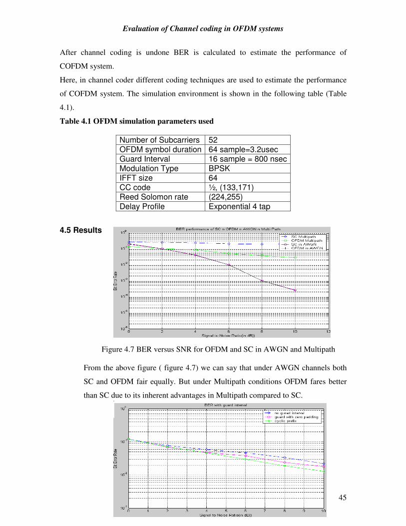
Evaluation of Channel coding in OFDM systems
NIT Rourkela 45
After channel coding is undone BER is calculated to estimate the performance of
COFDM system.
Here, in channel coder different coding techniques are used to estimate the performance
of COFDM system. The simulation environment is shown in the following table (Table
4.1).
Table 4.1 OFDM simulation parameters used
4.5 Results Figure 4.7 BER versus SNR for OFDM and SC in AWGN and Multipath
From the above figure ( figure 4.7) we can say that under AWGN channels both
SC and OFDM fair equally. But under Multipath conditions OFDM fares better
than SC due to its inherent advantages in Multipath compared to SC.
Number of Subcarriers 52 OFDM symbol duration 64 sample=3.2usec Guard Interval 16 sample = 800 nsec Modulation Type BPSK IFFT size 64 CC code ½, (133,171) Reed Solomon rate (224,255)
Delay Profile Exponential 4 tap

Evaluation of Channel coding in OFDM systems
NIT Rourkela 46
Figure 4.8 BER with changing guard interval In the figure 4.8 BER was plotted for three cases:
1) no guard interval
2) guard interval with zero padding
3) with cyclic prefix
From this figure (Figure 4.8) we can conclude that with cyclic prefix the BER was very
low compared to the other two schemes.
Figure 4.9 OFDM and SC performance with and without coding From the above figure (figure 4.9), it can be concluded that OFDM and SC doesn’t fair
well without coding. With coding OFDM outperforms SC in BER performance.
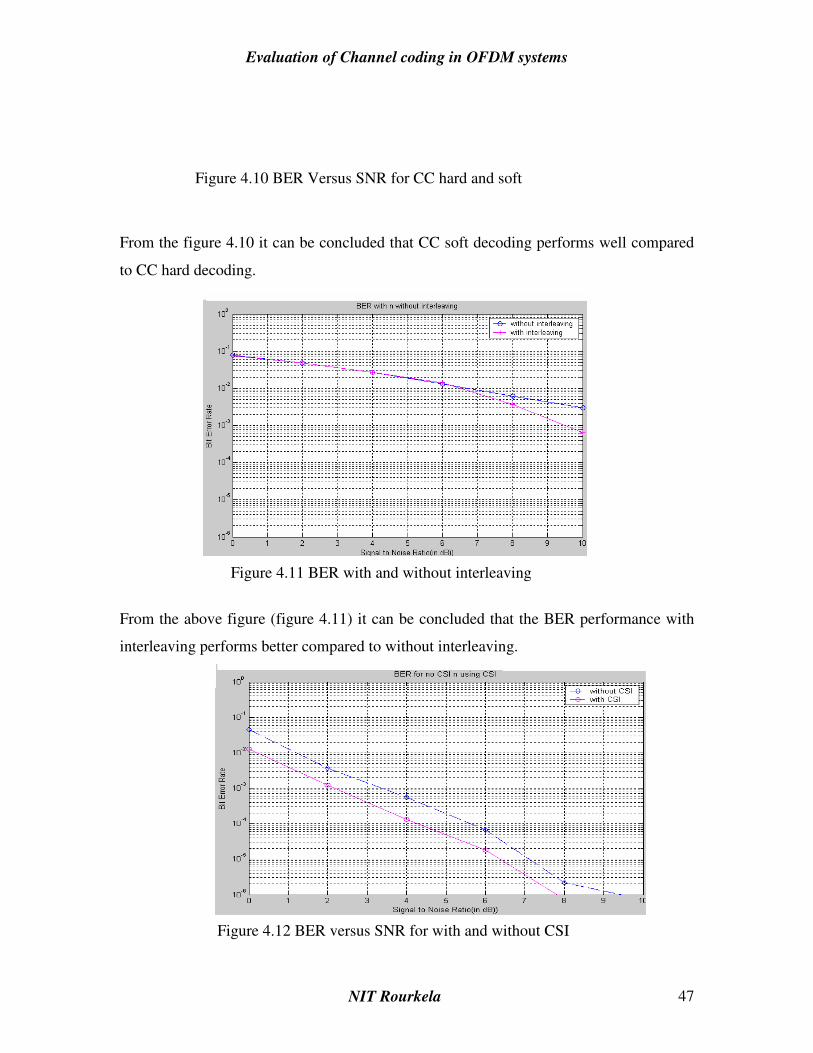
Evaluation of Channel coding in OFDM systems
NIT Rourkela 47
Figure 4.10 BER Versus SNR for CC hard and soft
From the figure 4.10 it can be concluded that CC soft decoding performs well compared
to CC hard decoding.
Figure 4.11 BER with and without interleaving
From the above figure (figure 4.11) it can be concluded that the BER performance with
interleaving performs better compared to without interleaving.
Figure 4.12 BER versus SNR for with and without CSI

Evaluation of Channel coding in OFDM systems
NIT Rourkela 48
From the above figure (figure 4.12) it can be concluded that the BER performance with
CSI performs better compared to without CSI.
Figure 4.13 BER versus SNR for No coding, Hamming coding, RS code, Convolutional code From the above figure (figure 4.13) it can be concluded that Convolutional coding
performs better than RS and Hamming coding.
RS coder Outer Interleaver
RS decoder Outer deinterleaver
Channel
Inner inetrleaver
Convolutional decoder
Convolutional coder
Inner Deinterleaver

Evaluation of Channel coding in OFDM systems
NIT Rourkela 49
Figure 4.14 RS-CC block diagram
Figure 4.14 BER Vs SNR for CC and RS-CC for hard and soft decoding From the above figure (figure 4.14) it can be concluded that Reed Solomon
Convolutional soft decoding performs better than Convolutional coding and RS-CC soft
decoding.

Evaluation of Channel coding in OFDM systems
NIT Rourkela 50
Figure 4.15 BER Vs SNR for Turbo coding and RS-Turbo coding From the above figure (figure 4.15) it can be concluded that RS-Turbo coding performs
better than Turbo coding.
4.5 Conclusion: Here OFDM and SC are compared and analysed in Multipath and AWGN environments.
Next for channel coding different coding techniques are analysed and their results are
compared. Of all the coding techniques discussed convolutional coding fares better.
Turbo coding also functions better. Next a combination of coding techniques like RS-CC
and RS-Turbo are discussed. Of these RS-Turbo fares better than all the coding
techniques discussed.

Evaluation of Channel coding in OFDM systems
NIT Rourkela 51
Chapter 5
SPACE FREQUENCY CODED OFDM
5.1 INTRODUCTION:
High data rate reliable transmission over wireless channels is seemingly possible due
to the advent of Space-time codes. Space-time codes rely on transmit diversity and
are particularly suitable when the signal undergoes frequency flat fading due to the
channel. This chapter discusses the performance of the OFDM with space frequency
coding technique. Following the introduction this chapter is organized as under
Section 5.2 describes the space frequency coding technique. Section 5.3 describes about
overloaded OFDM. Section 5.4 provides concluding remarks.
5.2 SPACE FREQUNENCY CODING TECHNIQUE
In the original space-time code scheme [32], Alamouti showed that it is possible to
obtain the same diversity as with multiple receivers. Since then, transmit diversity has
been pursued with great interest among the research community. However, the
fundamental assumption based on the which the scheme works is that that channel is
frequency flat, i.e., the coherence bandwidth of the channel is much smaller than
bandwidth of the signal which may not be true in wideband communication [2-
5]. This assumption may not be generally true in wideband communication systems.
For example, high-data rates are made possible with increased resources in terms of
bandwidth in WWAN and outdoor wireless WANs. There is need to developing new
technologies for providing wideband wireless communications.
OFDM has matured into a very practicable technique and has been incorporated into
the IEEE 802.11a [33]. OFDM splits the channel into sub-channels equal to the no. of carriers
under use. Each subchannel is treated independently and the multiplexed modulated symbols
are sent over each carrier. This operation is performed via IFFT at the transmitter side and
with FFT at the receiver side. This is another interesting aspect of OFDM.

Evaluation of Channel coding in OFDM systems
NIT Rourkela 52
Thus marrying OFDM with Space-time codes appears vary natural in frequency selective
fading scenarios. OFDM splits the channel into near frequency -flat subchannels and Space-
time codes exploit the transmit diversity under these frequency-flat sub-channels. Together
they form a promising technological alternative for high data rate broadband
communications. This space-frequency coded OFDM system [6] is shown in Fig. 5.1.
Figure 5.1 A space frequency coded OFDM system
Here, we simulate 2 x 1 Alamouti space-time code with OFDM (which is called as space-
fequency code, as the space-time codes are transmitted over another carrier rather than
another time-slot). A frequency selective Raleigh channel is assumed. Information bits are
M-ary PSK modulated, which are then converted into space-frequency codes. These are
multiplexed to form OFDM frames for final transmission. Symbol error rates are computed at
different bit-SNRs for different M in the M-ary PSK. Later on, ways are investigated to
improve the system. In particular, the performance of the system in which information
about few more symbols is spread over all the carriers by varying both the phase and energy of
that particular constellation in a controlled manner is studied. Details about the encoding
and decoding mechanisms are given. Symbol error rates are also compared.
Tx2
Y(n) X^(n)
X(n) Serial to Parallel
Parallel to serial
Space Frequency coder
Space frequency decoder
DFT and Cyclic prefix
Prefix removal and IDFT
Channel estimator
DFT and Cyclic prefix
X1(n)
X2 (n)
Tx1
Rx

Evaluation of Channel coding in OFDM systems
NIT Rourkela 53
System Description:
No. of carriers: Nc
Total Bandwidth: W Hz
Input symbols (M-ary coded) in a frame: Xo X1,...,XNc
Modulation: M-ary PSK
No. of Tx: 2
No. of Rx: 1
Space time code: Alamouti 2 x 2 code
hi(n) = ∑=
L
l
a1
i(n)δ(t-l/W)…………………………………….(4)
Channel Model [34,35, 36]:
No. of taps: L = 6
Where at are zero mean complex Gaussian random variables with variance 1/L
Hi (k) = ∑=
Nc
j
h1
i (j) exp(- j2πkn / Nc)………………………………….(5)
Space-frequency code at Tx -1 (total NC symbols) : X1 = [X0 – X1*,…..XNc-2 –XNc-1
*]T
Space-frequency code at Tx -2 (total NC symbols):X2 = [X1,X0*,…,XNc-1,X
*Nc-2]
T
Received symbols at the receiver:
Ye=A leX le+A l eX2e+Ne
Yo=AloXlo+A2oX2o+No where
Xie=Xi(2k)
Xio= Xi(2k+1), k =0,1,…Nc/2
and N ,Y ,A defined likewise.

Evaluation of Channel coding in OFDM systems
NIT Rourkela 54
٨ is a diagonal matrix with Hi(k) as its diagonal elements
The estimated (decoded) symbols (assuming that two adjacent sub-channels have
approximately same frequency response) after stripping the cyclic prefix and performing
FFT operation on the received symbols,
are [6],
This equation enables us to study the performance of the scheme completely in the
constellation domain.
Performance analysis
We studied the performance of the above scheme with different M-ary groupings and
different number of carriers. We varied the SNR from 0 to 20dB. M is varied at
from 2 to 4. As we can see from the graph in Fig. 2, the SER is decaying with almost
unity slope for all the schemes except the case with Nc=16. The reason might be
that, there bandwidth is too small to assume that the channels are frequency flat and
also the assumption that adjacent channels have approximately same frequency
response may also be violated. The effect of employing carriers from 256 to 512 did
not seem very significant as the capacity almost linearly adds up and the sub-channels
would tend to be frequency flat. However, this constant SER is at the expense
of bandwidth. The effect of varying M from 2 to 4 did shift the SER curve by about
2dB which is expected in M-ary modulation. To achieve the same SER, more power is
required so as to push the constellation further away from the origin.
5.3 Over-loaded OFDM
We tried to spread a message symbol onto all the carriers. An explanation is sought
to suggest a way of spreading the message symbols. In the OFDM case, message
symbols are modulated on to separate carriers which are orthogonal. Suppose if we
use time-varying signals to modulate these message symbols, we can overload the time-

Evaluation of Channel coding in OFDM systems
NIT Rourkela 55
frequency plane i.e., besides all the carriers, we can modulate some additional symbols
using these time-varying signals. In the context of M-ary FSK, this affects the
constellation in two ways:
The phase as well as radius of the constellation is varied. In the regular M-ary
OFDM, the constellation is cylinder. The radius is equal to the symbol energy and
each section of the cylinder corresponds to a carrier. When chirp signals are used to
modulate additional symbols, then, the phase of the message symbol in a particular is
corrupted by the phase of the chirp signal and phase of the message symbols this
chirp signal is carrying. The radius is affected by the addition of instantaneous
energy of the chirp signal. The modified constellation can be represented as:
These modified symbols 'are now used to form the space-frequency codes. The decoding is
performed by inverting the weight matrix to obtain an approximate Nc+Ne constellation
vectors which is subjected to M-ary PSK detection. In the simulation studies, we have
used BPSK modulation with Nc=256 and Ne=l. The choice of the weight matrix affects the
performance matrix severely. It is of much interest to study how to do design the weight
matrix for a given modulation and given number of carriers. Our initial results were not
promising and a careful study to construct such pseudo orthogonal weight matrix is of great
interest.

Evaluation of Channel coding in OFDM systems
NIT Rourkela 56
5.4 Simulation Results
Figure 5.2 SER Vs EbNo for 64 ary PSK
5.5 Conclusions:
For large number of carriers for a given band-width, the SER rate is almost the
same. This is because, the sub-channels are frequency flat, and each sub-channel can be
used to its full capacity. The assumption that adjacent sub-channels are identical is
also valid. Increasing M, the SER shifts by 2dB. This is expected because, to achieve the
same SER, more power is required to push the constellation further away from the
origin to offer more resolution or detection capability. The intial weight matrix we
have chosen was not performing as expected. We expect that there should be no
degradation in the SER because, the Ne symbols are spread over all the carriers
and all the carriers suffers independent fading. So we expect frequency diversity to
offer some advantage here. This lets us think to design new weight pseudo
orthogonal matrices.

Evaluation of Channel coding in OFDM systems
NIT Rourkela 57
Chapter 6
CONCLUSION
6.1 Introduction
The work undertaken in this thesis primarily discusses coded OFDM systems and SFC
OFDM system. The implementation of OFDM model is presented. The capability of
OFDM in Rayleigh faded channels have been analyzed. This thesis analyzes OFDM
system and the effect of channel coding in reducing BER. Along with this soft decoding
and decoding with CSI is also studied. Besides, performance of convolutional codes
Turbo codes in OFDM systems is compared and compared. Besides, the performance of
convolution and turbo codes in OFDM systems is compared. This chapter summarizes
the work reported in this thesis, specifying the limitations of the study and provides some
pointers to future development.
Following this introduction section 6.2 lists the achievements from the work undertaken.
Section 6.3 provides the limitations and section 6.4 presents few pointers towards the
future work.
6.2 Achievement of the thesis
The work presented in this thesis can be classified into two parts. The first part presents
the measure of the performance of OFDM system in AWGN and frequency selective
channels and the other part is dedicated for COFDM. Major points of the thesis,
highlighting the contributions at each stage, are presented below.
Chapter 2 of this thesis discusses about the fundamental concepts and principles of
OFDM Chapter 3 of this thesis presents the implementation of OFDM. We investigated
OFDM as an attractive means of transmitting high rate information over highly dispersive
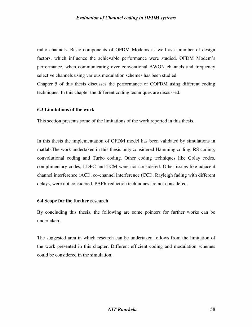
Evaluation of Channel coding in OFDM systems
NIT Rourkela 58
radio channels. Basic components of OFDM Modems as well as a number of design
factors, which influence the achievable performance were studied. OFDM Modem’s
performance, when communicating over conventional AWGN channels and frequency
selective channels using various modulation schemes has been studied.
Chapter 5 of this thesis discusses the performance of COFDM using different coding
techniques. In this chapter the different coding techniques are discussed.
6.3 Limitations of the work
This section presents some of the limitations of the work reported in this thesis.
In this thesis the implementation of OFDM model has been validated by simulations in
matlab.The work undertaken in this thesis only considered Hamming coding, RS coding,
convolutional coding and Turbo coding. Other coding techniques like Golay codes,
complimentary codes, LDPC and TCM were not considered. Other issues like adjacent
channel interference (ACI), co-channel interference (CCI), Rayleigh fading with different
delays, were not considered. PAPR reduction techniques are not considered.
6.4 Scope for the further research
By concluding this thesis, the following are some pointers for further works can be
undertaken.
The suggested area in which research can be undertaken follows from the limitation of
the work presented in this chapter. Different efficient coding and modulation schemes
could be considered in the simulation.

Evaluation of Channel coding in OFDM systems
NIT Rourkela 59
REFERENCES
[1] Mosier, R. R., and Clabaugh, R.G., A Bandwidth Efficient Binary Transmission
System, IEEE Trans., Vol. 76, pp. 723 - 728, Jan. 1958.
[2] Salzberg, B. R., Performance of an efficient parallel data transmission system, IEEE
Trans. Comm., Vol. COM- 15, pp. 805 - 813, Dec. 1967.
[3] Orthogonal Frequency Division Multiplexing, U.S. Patent No. 3, 488,4555, filed
November 14, 1966, issued Jan. 6, 1970.
[4] S. Weinstein and P. Ebert, "Data transmission by frequency-division multiplexing
using the discrete Fourier transform," IEEE Trans. on Communications., vol. 19, pp.
628--634, Oct. 1971
[5] R.W. Chang, and R.A. Gibby [1968], “Theoretical Study of Performance of an
Orthogonal Multiplexing Data Transmission Scheme,” IEEE Transactions on
Communications, 16, 4, pp. 529-540.
[6] A. Peled and A. Ruiz, "Frequency domain data transmission using reduced
computationally complexity algorithms," in Proceedings of IEEE International
Conference of Acoustics, Speech and Signal Processing, (Denver), pp. 964--967, April
1980.
[7] B. Hirosaki. An Orthogonally Multiplexed QAM System Using the Discrete Fourier
Transform. IEEE Trans. on Commun., 29(7):982-989, July 1981.
[8] L.J. Cimini [1985], “Analysis and Simulation of a Digital Mobile Channel Using
Orthogonal Frequency-Division Multiplexing,” IEEE Transactions on Communications,
33, 7, pp. 665-675
[9] R. Gross, and D. Veeneman [1993], “Clipping Distortion in DMT ADSL Systems,”
Electronics Letters, 29, 24, pp. 2080-2081

Evaluation of Channel coding in OFDM systems
NIT Rourkela 60
[10] P.J. Tourtier, R. Monnier, and P. Lopez [1993], “Multicarrier Modem for Digital
HDTV Terrestrial Broadcasting,” Signal Processing: Image Communication, 5, 5/6, pp.
379-403.
[11] Wireless LAN Medium Access Control (MAC) and Physical Layer (PHY)
Specification, IEEE Standard, Supplement to Standard 802 Part 11: Wireless LAN, New
York, NY, 1999.
[12] http://wirelessafrica.meraka.org.za/wiki/index.php/Wireless_Network_Technology
[13] Performance evaluation of a multichannel transceiver system for ADSL and
VHDSL services Chow Tu JC, Cioffi, J.M.IEEE commns Aug. 1991 Volume: 9, Issue: 6
pages: 909 - 919
[14] “Analysis of new methods for broadcasting digital data to mobile terminals over an
FM channel” Prasad.R and Bons JH This paper appears in: Broad casting ,IEEE
transactions Volume: 40 , Issue: 1 pages: 29 - 37
[15] On multi rate DS/CDMA with interference cancellation for wireless multi media
applications Johansson, Ottossonm, svensson personal wireless comm, 1996, IEEE Vol 5,
pages 102-107
[16] Discrete Multitone Transceiver System for HDSL. Applications. Jacky. S. Chow,
Student Member, IEEE, Jeny C. Tu, Student Member, IEEE,. and John. M. Cioffi, IEEE
Commun. Mag., vol. 16, pp. 654-665, March 1995
[17] Transmission capacity and design of a VHDSL system Schmucking. D.,Worner. A
IEEE International conference on Communications June 1996 Vol: 3 pages: 1426 - 1431
[18] J. A. C. Bingham, \Multicarrier modulation for data transmission: An idea whose
time has come," IEEE Commun. Mag., vol. 28, pp. 5-14, May 1991.
[19] B. Lu, X. Wang, and K. R. Narayanan, LDPC-based space-time coded OFDM
systems over correlated fading channels: Performance analysis and receiver design,"
IEEE Trans. Wireless Commun., vol. 1, pp. 213-225, Apr. 2002.
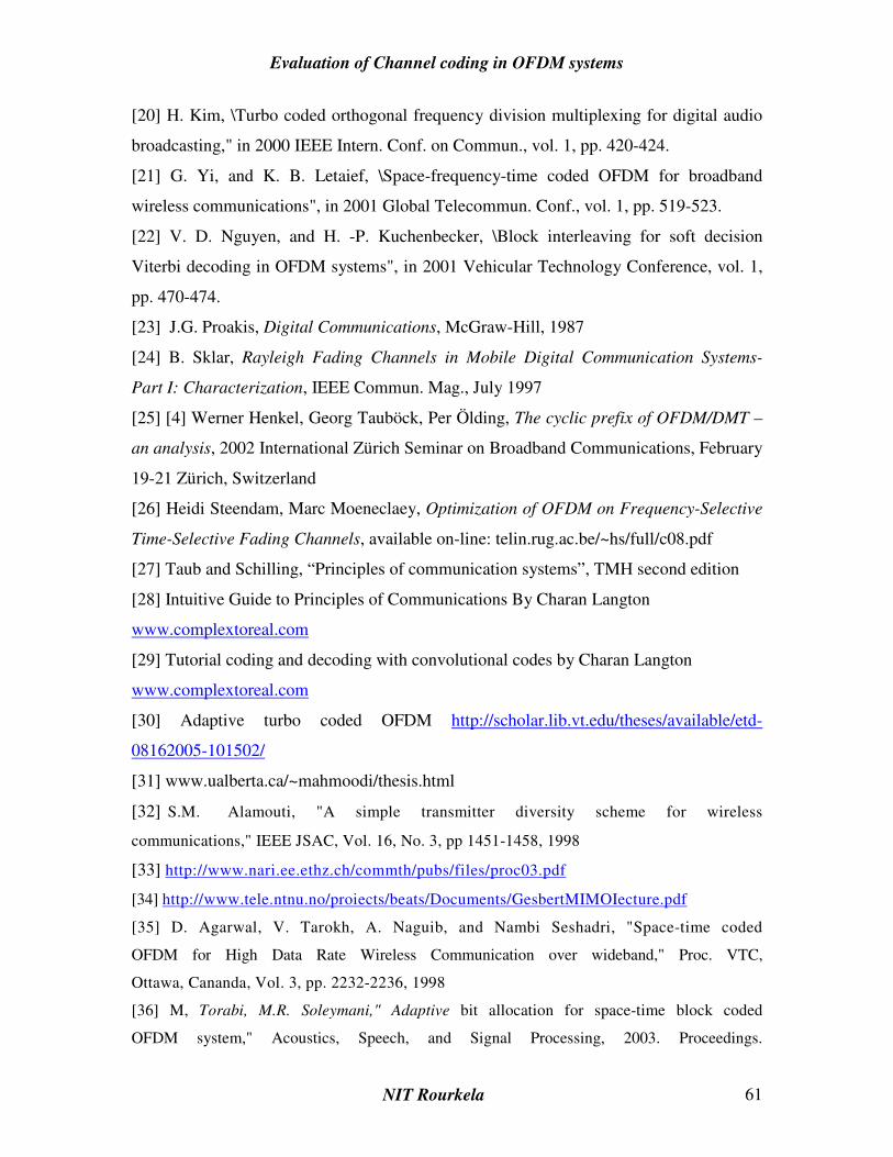
Evaluation of Channel coding in OFDM systems
NIT Rourkela 61
[20] H. Kim, \Turbo coded orthogonal frequency division multiplexing for digital audio
broadcasting," in 2000 IEEE Intern. Conf. on Commun., vol. 1, pp. 420-424.
[21] G. Yi, and K. B. Letaief, \Space-frequency-time coded OFDM for broadband
wireless communications", in 2001 Global Telecommun. Conf., vol. 1, pp. 519-523.
[22] V. D. Nguyen, and H. -P. Kuchenbecker, \Block interleaving for soft decision
Viterbi decoding in OFDM systems", in 2001 Vehicular Technology Conference, vol. 1,
pp. 470-474.
[23] J.G. Proakis, Digital Communications, McGraw-Hill, 1987
[24] B. Sklar, Rayleigh Fading Channels in Mobile Digital Communication Systems-
Part I: Characterization, IEEE Commun. Mag., July 1997
[25] [4] Werner Henkel, Georg Tauböck, Per Ölding, The cyclic prefix of OFDM/DMT –
an analysis, 2002 International Zürich Seminar on Broadband Communications, February
19-21 Zürich, Switzerland
[26] Heidi Steendam, Marc Moeneclaey, Optimization of OFDM on Frequency-Selective
Time-Selective Fading Channels, available on-line: telin.rug.ac.be/~hs/full/c08.pdf
[27] Taub and Schilling, “Principles of communication systems”, TMH second edition
[28] Intuitive Guide to Principles of Communications By Charan Langton
www.complextoreal.com
[29] Tutorial coding and decoding with convolutional codes by Charan Langton
www.complextoreal.com
[30] Adaptive turbo coded OFDM http://scholar.lib.vt.edu/theses/available/etd-
08162005-101502/
[31] www.ualberta.ca/~mahmoodi/thesis.html
[32] S.M. Alamouti, "A simple transmitter diversity scheme for wireless
communications," IEEE JSAC, Vol. 16, No. 3, pp 1451-1458, 1998
[33] http://www.nari.ee.ethz.ch/commth/pubs/files/proc03.pdf
[34] http://www.tele.ntnu.no/proiects/beats/Documents/GesbertMIMOIecture.pdf
[35] D. Agarwal, V. Tarokh, A. Naguib, and Nambi Seshadri, "Space-time coded
OFDM for High Data Rate Wireless Communication over wideband," Proc. VTC,
Ottawa, Cananda, Vol. 3, pp. 2232-2236, 1998
[36] M, Torabi, M.R. Soleymani," Adaptive bit allocation for space-time block coded
OFDM system," Acoustics, Speech, and Signal Processing, 2003. Proceedings.

Evaluation of Channel coding in OFDM systems
NIT Rourkela 62
(ICASSP '03). 2003 IEEE International Conference on, Volume: 4, 6-10 April
2003, Pages: IV - 409-12 vol.4