evaluation of corrosion of metallic ... of corrosion of metallic reinforcements and connections in...
TRANSCRIPT
EVALUATION OF CORROSION OF METALLIC REINFORCEMENTS AND CONNECTIONS IN MSE RETAINING
WALLS
Final Report
SPR 643

EVALUATION OF CORROSION OF METALLIC REINFORCEMENTS AND
CONNECTIONS IN MSE RETAINING WALLS
Final Report
PROJECT 643
by
Christopher L. Raeburn, M. Murat Monkul, and Marvin R. Pyles School of Civil and Construction Engineering,
Oregon State University
for
Oregon Department of Transportation Research Unit
200 Hawthorne Ave. SE, Suite B-240 Salem OR 97301-5192
and
Federal Highway Administration
400 Seventh Street, SW Washington, DC 20590-0003
May 2008

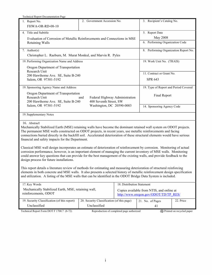
Technical Report Documentation Page
1. Report No. FHWA-OR-RD-08-10
2. Government Accession No.
3. Recipient’s Catalog No.
5. Report Date May 2008
4. Title and Subtitle
Evaluation of Corrosion of Metallic Reinforcements and Connections in MSE Retaining Walls 6. Performing Organization Code
7. Author(s)
Christopher L. Raeburn, M. Murat Monkul, and Marvin R. Pyles 8. Performing Organization Report No.
19. Work Unit No. (TRAIS)
19. Performing Organization Name and Address
Oregon Department of Transportation Research Unit 200 Hawthorne Ave. SE, Suite B-240 Salem, OR 97301-5192
11. Contract or Grant No.
SPR 643
19. Type of Report and Period Covered Final Report
19. Sponsoring Agency Name and Address
Oregon Department of Transportation Research Unit and Federal Highway Administration 200 Hawthorne Ave. SE, Suite B-240 400 Seventh Street, SW Salem, OR 97301-5192 Washington, DC 20590-0003
14. Sponsoring Agency Code
19. Supplementary Notes 16. Abstract
Mechanically Stabilized Earth (MSE) retaining walls have become the dominant retained wall system on ODOT projects. The permanent MSE walls constructed on ODOT projects, in recent years, use metallic reinforcements and facing connections buried directly in the backfill soil. Accelerated deterioration of these structural elements would have serious financial and safety impacts for the Department.
Classical MSE wall design incorporates an estimate of deterioration of reinforcement by corrosion. Monitoring of actual corrosion performance, however, is an important element of managing the current inventory of MSE walls. Monitoring could answer key questions that can provide for the best management of the existing walls, and provide feedback to the design process for future installations.
This report details a literature review of methods for estimating and measuring deterioration of structural reinforcing elements in both concrete and MSE walls. It also presents a selected history of metallic reinforcement design specification and utilization. A listing of the MSE walls that can be identified in the ODOT Bridge Data System is included.
17. Key Words Mechanically Stabilized Earth, MSE, retaining wall, reinforcements, ODOT
18. Distribution Statement
Copies available from NTIS, and online at http://www.oregon.gov/ODOT/TD/TP_RES/
19. Security Classification (of this report) Unclassified
20. Security Classification (of this page) Unclassified
21. No. of Pages 41
22. Price
Technical Report Form DOT F 1700.7 (8-72) Reproduction of completed page authorized Printed on recycled paper
i
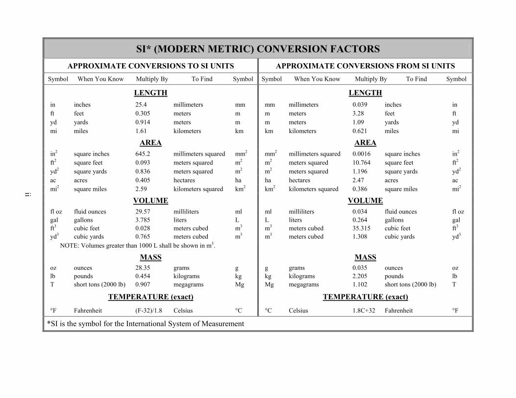
SI* (MODERN METRIC) CONVERSION FACTORS APPROXIMATE CONVERSIONS TO SI UNITS APPROXIMATE CONVERSIONS FROM SI UNITS
Symbol When You Know Multiply By To Find Symbol Symbol When You Know Multiply By To Find Symbol
LENGTH LENGTH
in inches 25.4 millimeters mm mm millimeters 0.039 inches in ft feet 0.305 meters m m meters 3.28 feet ft yd yards 0.914 meters m m meters 1.09 yards yd mi miles 1.61 kilometers km km kilometers 0.621 miles mi
AREA AREA
in2 square inches 645.2 millimeters squared mm2 mm2 millimeters squared 0.0016 square inches in2
ft2 square feet 0.093 meters squared m2 m2 meters squared 10.764 square feet ft2 yd2 square yards 0.836 meters squared m2 m2 meters squared 1.196 square yards yd2 ac acres 0.405 hectares ha ha hectares 2.47 acres ac mi2 square miles 2.59 kilometers squared km2 km2 kilometers squared 0.386 square miles mi2
VOLUME
ii
VOLUME
fl oz fluid ounces 29.57 milliliters ml ml milliliters 0.034 fluid ounces fl oz gal gallons 3.785 liters L L liters 0.264 gallons gal ft3 cubic feet 0.028 meters cubed m3 m3 meters cubed 35.315 cubic feet ft3 yd3 cubic yards 0.765 meters cubed m3 m3 meters cubed 1.308 cubic yards yd3
NOTE: Volumes greater than 1000 L shall be shown in m3.
MASS MASS
oz ounces 28.35 grams g g grams 0.035 ounces oz lb pounds 0.454 kilograms kg kg kilograms 2.205 pounds lb T short tons (2000 lb) 0.907 megagrams Mg Mg megagrams 1.102 short tons (2000 lb) T
TEMPERATURE (exact) TEMPERATURE (exact)
°F Fahrenheit (F-32)/1.8 Celsius °C °C Celsius 1.8C+32 Fahrenheit °F
*SI is the symbol for the International System of Measurement
ACKNOWLEDGEMENTS
This report was originally written as an interim report for the project. It is being published as the final project report because health problems prevented the principle investigator from continuing the project. The ODOT Research Unit wishes to thank Professor Marvin R. Pyles for graciously stepping in to help finish the interim report and bring the project to closure. Graduate students Christopher L. Raeburn and M. Murat Monkul are to be congratulated for soldiering on with the project even while their professor was ill.
DISCLAIMER
This document is disseminated under the sponsorship of the Oregon Department of Transportation and the United States Department of Transportation in the interest of information exchange. The State of Oregon and the United States Government assume no liability of its contents or use thereof. The contents of this report reflect the view of the authors who are solely responsible for the facts and accuracy of the material presented. The contents do not necessarily reflect the official views of the Oregon Department of Transportation or the United States Department of Transportation. The State of Oregon and the United States Government do not endorse products of manufacturers. Trademarks or manufacturers’ names appear herein only because they are considered essential to the object of this document. This report does not constitute a standard, specification, or regulation.
iii

iv
v
TABLE OF CONTENTS
1.0 INTRODUCTION............................................................................................................. 1
2.0 HISTORY OF MECHANICALLY STABILIZED EARTH WALLS AND METALLIC REINFORCEMENT UTILIZATION.................................................................. 3
2.1 CURRENT DESIGN ASPECTS OF MSE WALLS AND CORROSION RELATED ISSUES................ 7 2.1.1 General design considerations ..............................................................................................................7 2.1.2 Backfill material ....................................................................................................................................7 2.1.3 Reinforcing material..............................................................................................................................8 2.1.4 Connections ...........................................................................................................................................9
2.2 PROBLEMS WITH MSE WALLS IN OTHER STATES ............................................................. 11
3.0 REINFORCEMENT CORROSION............................................................................. 13
3.1 CORROSION DETECTION ................................................................................................. 13 3.1.1 Destructive Testing Methods ...............................................................................................................13 3.1.2 Non-Destructive Techniques................................................................................................................14
3.2 WALL PERFORMANCE .................................................................................................... 18
4.0 ODOT MSE WALL ELECTRONIC DATABASE ..................................................... 21
5.0 REFERENCES................................................................................................................ 23
APPENDIX A: STATE DOT QUESTIONNAIRE AND RESULTS
LIST OF TABLES
Table 2.1: Effect of resistivity on corrosion (Elias, 2000) ............................................................................................7 Table 2.2: Table summarizing various backfill requirements for some State DOTs.....................................................8 Table 2.3: AASHTO recommended corrosion rates for design.....................................................................................8 Table 3.1 Criteria for the use of backfill soils when used for out-of-water structures (Bastick 1992)........................18 Table 3.2: Criteria for the use of backfill soils according to AASHTO Standards (Elias, 2000)................................18 Table 4.1: Table showing the existing ODOT MSE retaining structures (as generated from a database) ..................21
LIST OF FIGURES
Figure 2.1: Cost comparison of reinforced wall systems (adapted from Koerner, 1998)..............................................4 Figure 2.2: Map of Georgia depicting the location of some MSE walls .......................................................................4 Figure 2.3: Metallic reinforcement types in various regions of the United States (AMSE, 2006).................................6 Figure 2.4: Example diagrams of connectors used in some MSE walls ......................................................................10 Figure 2.5: Photos of some problems experienced in MSE walls (after Narsavage, 2006) ........................................12 Figure 3.1: Diagram showing the upper limit for 30-year zinc life .............................................................................15 Figure 3.2: Corrosion of galvanized steel in soils complying with standard. Summary of results (Bastick 1992) ....17

1.0 INTRODUCTION
Mechanically Stabilized Earth (MSE) retaining walls have become the dominant retained wall system on Oregon Department of Transportation (ODOT) projects. MSE walls accounted for approximately 70% of the total wall surface area constructed over the period from 2001 through 2004. These MSE walls are intended to provide a long-term (75+ year) service life. However, all of the permanent MSE walls constructed on ODOT projects in recent years use metallic reinforcements and facing connections buried directly in the backfill soil. Accelerated deterioration of these structural elements would have serious financial and safety impacts for the Department.
Classical MSE wall design incorporates an estimate of deterioration of reinforcement by corrosion. Monitoring of actual corrosion performance, however, is an important element of managing the current inventory of MSE walls. Monitoring could answer key questions that can provide for the best management of the existing walls and provide feedback to the design process for future installations.
Some of the key questions include: • How well are the reinforcing materials performing? • Are the metallic reinforcements degrading at an acceptable rate, in terms of the 75-year
service life? • Are design/specification changes needed to ensure acceptable longevity of MSE wall
assets?
This project will begin to address these basic questions. This report details a literature review of methods for estimating and measuring deterioration of structural reinforcing elements in both concrete and MSE walls. It will also present a selected history of metallic reinforcement design specification and utilization, and present a listing of the MSE walls that can be identified in the ODOT Bridge Data System.
1

2

2.0 HISTORY OF MECHANICALLY STABILIZED EARTH WALLS AND METALLIC REINFORCEMENT UTILIZATION
Mechanically Stabilized Earth Retaining Walls (MSE) is the general name for retaining structures that employ either metallic or geosynthetic reinforcement, in soil, that is connected to a facing panel (i.e. pre-cast concrete or prefabricated metal) to form a reinforced soil body.
The use of MSE walls is known to date back to the mid-1960’s in Europe. In 1963, the Reinforced Earth Company filed for a patent on a type of Mechanically Stabilized Earth Retaining Wall developed by French engineer Henri Vidal. The first Reinforced Earth wall in the United States was constructed in 1972 on California State Highway 39, northeast of Los Angeles (Elias et al. 2001). In Oregon, a metal reinforced earth wall, apparently designed to look like a tied-back wall (as a protection against any potential patent infringement challenge) was constructed on the road up Mary’s Peak by the U.S Forest Service.
Brunswick, Georgia is home to the first MSE wall constructed in a corrosive marine environment in the United States (McGee 1985). The wall is approximately 1100 ft long, 30 ft wide and 25 ft high. The reinforcing strips of this wall were reported as aluminum magnesium alloy. Another exceptional reinforcing style was the un-galvanized steel welded wire fabric used in an MSE wall in Las Vegas, Nevada (AMSE 2006). However, we believe that the current specifications of all state DOTs allows only the usage of galvanized steel as metallic reinforcement in MSE walls.
In the past 35 years, numerous MSE walls have been built in the United States for bridge abutments, marine structures, residential and commercial structures, approach ramps, railways and rapid transit structures. The highest wall constructed in United States was reported to be 98 ft (10m) high (Elias et al. 2001). Although metallic facing has been used on a number of occasions, the most common facing material used in high-volume road applications, by various state departments of transportation, are concrete panels. Between 1972 and the early 1990’s, 24 ft2 (2.25 m2) concrete facing panels were the preferred type for use in the United States. Recently, larger sizes with various sections, including rectangular shape, have also been widely used. In 1996 Colorado DOT built full height concrete facing panels that are allowed to tilt about their base (Abu-Hejleh et al. 2001).
Geosynthetic reinforcements started to be used as an alternative to metallic reinforcements in the United States in 1974, after they were first used in France in 1971. Starting from the early 1980’s, geosynthetic reinforcements started to be utilized increasingly in the US market. Figure 2.1 below provides a brief insight and comparison between different wall systems from an economic perspective. Currently, there are different visions regarding reinforcement type in the US market, one example is an organization named Association for Metallically Stabilized Earth (AMSE), who expressed their mission in their website as the promotion of steel reinforcement in mechanically stabilized earth retaining structures.
3
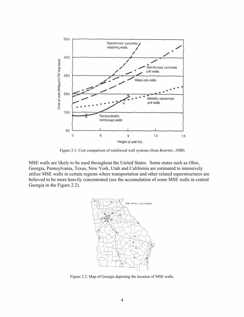
Figure 2.1: Cost comparison of reinforced wall systems (from Koerner, 1998)
MSE walls are likely to be used throughout the United States. Some states such as Ohio, Georgia, Pennsylvania, Texas, New York, Utah and California are estimated to intensively utilize MSE walls in certain regions where transportation and other related superstructures are believed to be more heavily concentrated (see the accumulation of some MSE walls in central Georgia in the Figure 2.2).
Figure 2.2: Map of Georgia depicting the location of MSE walls.
4

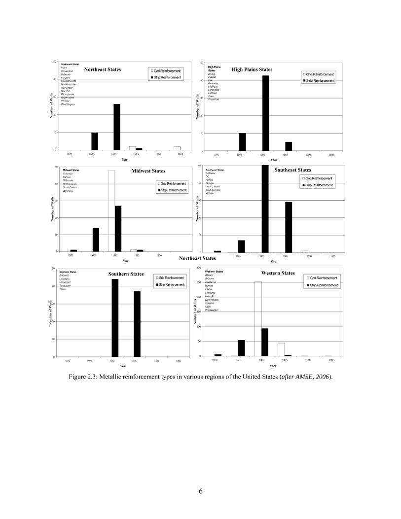
In 2006, AMSE performed a survey on 780 randomly sampled MSE walls constructed in the United States since 1972. Their dates of construction ranged from 1973 through 1999, but well over half of the walls in the survey were constructed between 1980 and 1985. Most of the walls were owned by state DOTs and were, therefore, designed and constructed based on AASHTO specifications. Walls owned by the US Forest Service, other government agencies and private owners may not have been built according to AASHTO specifications (AMSE 2006).
The AMSE survey included 271 walls constructed with wire mesh or grid-type steel reinforcements and 509 walls constructed with steel strips. The majority of MSE walls constructed with grid reinforcement served as retaining walls. One third of the walls with strip reinforcements served as part of a bridge structure (abutments or wing walls) (AMSE 2006). The surveyed MSE walls were grouped into six geographic regions (Figure 2.3). These regions, which were postulated to distinguish climatic conditions on a regional scale, are Northeast, High Plains, Midwestern, Southeast, Southern, and Western (AMSE 2006). Half (370) of the total MSE walls chosen for the survey were in the Western Region, which includes Oregon. One interesting point for the Western region is the sharp increase in the utilization of metallic grid reinforcement in 1980s. Whether the use of metallic grid reinforcement in Oregon follows this trend is not known.
5
Northeast States High Plains States
Southeast States Midwest States
Northeast States
Western States Southern States
Figure 2.3: Metallic reinforcement types in various regions of the United States (after AMSE, 2006).
6
2.1 CURRENT DESIGN ASPECTS OF MSE WALLS AND CORROSION RELATED ISSUES
2.1.1 General design considerations
Design of a conventional MSE wall consists of the following steps (Vulova and Leshchinsky, 2003):
• Specification of the design input data (i.e. wall and soil parameters, design life etc.) • Preliminary sizing • External stability analysis • Internal stability analysis • Connection design • Deformation and settlement calculations
The details regarding these steps and other design issues can be found in various FHWA and AASHTO technical documents.
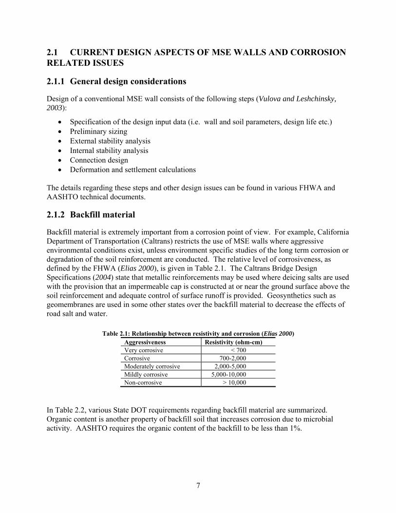
2.1.2 Backfill material
Backfill material is extremely important from a corrosion point of view. For example, California Department of Transportation (Caltrans) restricts the use of MSE walls where aggressive environmental conditions exist, unless environment specific studies of the long term corrosion or degradation of the soil reinforcement are conducted. The relative level of corrosiveness, as defined by the FHWA (Elias 2000), is given in Table 2.1. The Caltrans Bridge Design Specifications (2004) state that metallic reinforcements may be used where deicing salts are used with the provision that an impermeable cap is constructed at or near the ground surface above the soil reinforcement and adequate control of surface runoff is provided. Geosynthetics such as geomembranes are used in some other states over the backfill material to decrease the effects of road salt and water.
Table 2.1: Relationship between resistivity and corrosion (Elias 2000) Aggressiveness Resistivity (ohm-cm) Very corrosive < 700 Corrosive 700-2,000 Moderately corrosive 2,000-5,000 Mildly corrosive 5,000-10,000 Non-corrosive > 10,000
In Table 2.2, various State DOT requirements regarding backfill material are summarized. Organic content is another property of backfill soil that increases corrosion due to microbial activity. AASHTO requires the organic content of the backfill to be less than 1%.
7
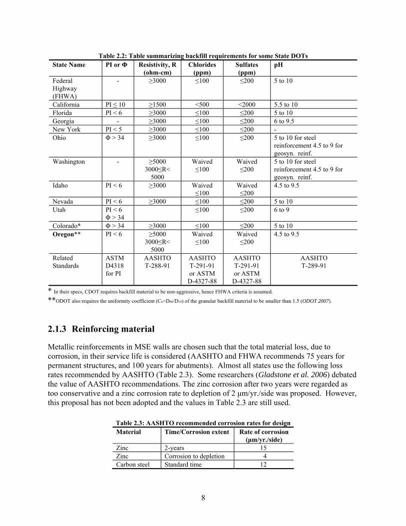
Table 2.2: Table summarizing backfill requirements for some State DOTs State Name PI or Φ Resistivity, R
(ohm-cm) Chlorides
(ppm) Sulfates (ppm)
pH
Federal Highway (FHWA)
- ≥3000 ≤100 ≤200 5 to 10
California PI ≤ 10 ≥1500 <500 <2000 5.5 to 10 Florida PI < 6 ≥3000 ≤100 ≤200 5 to 10 Georgia - ≥3000 ≤100 ≤200 6 to 9.5 New York PI < 5 ≥3000 ≤100 ≤200 - Ohio Φ > 34 ≥3000 ≤100 ≤200 5 to 10 for steel
reinforcement 4.5 to 9 for geosyn. reinf.
Washington - ≥5000 3000≤R<
5000
Waived ≤100
Waived ≤200
5 to 10 for steel reinforcement 4.5 to 9 for geosyn. reinf.
Idaho PI < 6 ≥3000 Waived ≤100
Waived ≤200
4.5 to 9.5
Nevada PI < 6 ≥3000 ≤100 ≤200 5 to 10 Utah PI < 6
Φ > 34 ≤100 ≤200 6 to 9
Colorado* Φ > 34 ≥3000 ≤100 ≤200 5 to 10 Oregon** PI < 6 ≥5000
3000≤R< 5000
Waived ≤100
Waived ≤200
4.5 to 9.5
Related Standards
ASTM D4318 for PI
AASHTO T-288-91
AASHTO T-291-91 or ASTM
D-4327-88
AASHTO T-291-91 or ASTM
D-4327-88
AASHTO T-289-91
* In their specs, CDOT requires backfill material to be non-aggressive, hence FHWA criteria is assumed.
**ODOT also requires the uniformity coefficient (Cu=D60/D10) of the granular backfill material to be smaller than 1.5 (ODOT 2007).
2.1.3 Reinforcing material
Metallic reinforcements in MSE walls are chosen such that the total material loss, due to corrosion, in their service life is considered (AASHTO and FHWA recommends 75 years for permanent structures, and 100 years for abutments). Almost all states use the following loss rates recommended by AASHTO (Table 2.3). Some researchers (Gladstone et al. 2006) debated the value of AASHTO recommendations. The zinc corrosion after two years were regarded as too conservative and a zinc corrosion rate to depletion of 2 μm/yr./side was proposed. However, this proposal has not been adopted and the values in Table 2.3 are still used.
Table 2.3: AASHTO recommended corrosion rates for design Material Time/Corrosion extent Rate of corrosion
(μm/yr./side) Zinc 2-years 15 Zinc Corrosion to depletion 4 Carbon steel Standard time 12
8

The necessary sacrificial steel thickness, calculated according to the values given above, must be added to the load-carrying cross section in order to produce the design cross section. FHWA recommends a factor of safety of 1.8 for each strip, and 2.1 for grid reinforcing, when calculating the allowable tensile force on reinforcement (Elias et al. 2001) – it is not clear if this difference in the recommended factor of safety addresses corrosion differences, or only structural performance differences.
As mentioned before, it is mandatory to galvanize steel before utilizing it as reinforcement. The advantages of galvanization were listed by Gladstone et al. (2006) as: (1) minimizing the surface irregularities and their contributions to corrosion, (2) significantly lower consumption rate of zinc compared to steel, and (3) passivation of steel due to zinc oxides which lowers the rate of steel consumption for galvanized steel, compared to steel that was never galvanized.
2.1.4 Connections
Connectors in modern MSE walls are metallic as well and may be subject to corrosion. For this reason it is better for all connection appurtenances to be galvanized. Figure 2.4, below shows three examples of trademarked connections used in some MSE walls.
9
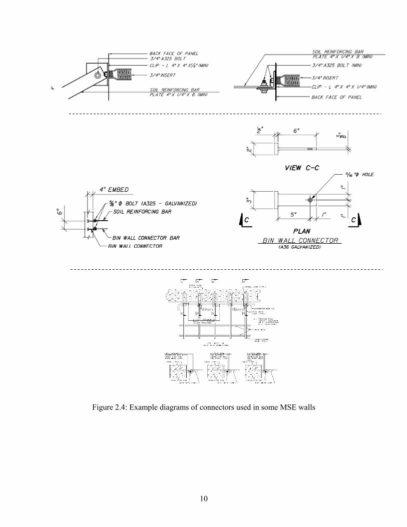
Figure 2.4: Example diagrams of connectors used in some MSE walls
10
2.2 PROBLEMS WITH MSE WALLS IN OTHER STATES
A questionnaire regarding MSE walls was sent to various DOTs nationwide (Appendix A). Nevada and Idaho indicated that they had constructed between 20 and 100 MSE walls, while New York, Georgia, Utah, California, Ohio and Colorado had each built more than 100 MSE walls. Among these states, only Colorado and New York utilized steel reinforcement in less than half of the MSE walls built in the last five years. Of the total wall inventory, only Colorado used steel reinforcement less than half the time.
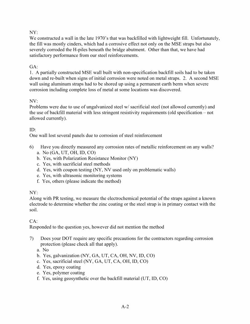
The DOTs of New York, Georgia, Nevada, California and Idaho reported that they had previously experienced some problems regarding the corrosion of steel reinforcements. New York DOT reported that they observed corrosion in an MSE wall at a bridge abutment constructed in the late 1970’s. Corrosion was also observed in H-piles beneath that bridge abutment. The cause was likely lightweight fill material consisting mostly of cinders. Georgia DOT reported two cases: 1) a partially constructed MSE wall, built with non-specification backfill soils, had to be taken down and re-built when signs of initial corrosion were noted on metallic reinforcement; and 2) an MSE wall with aluminum straps had to be shored up using a permanent earth berm when severe corrosion, including complete loss of metal at some locations, was discovered. Nevada DOT reported that they faced problems due to utilization of ungalvanized steel (currently not allowed) with sacrificial thickness, and also backfill with less stringent resistivity requirements (old specification – not allowed currently). Idaho DOT reported that one of their MSE walls lost several panels due to corrosion of steel reinforcement.
In terms of direct measurement of corrosion rates, only New York, Nevada, and California DOTs responded that they have previously measured corrosion rates on some problematic walls. New York DOT performed polarization resistance and coupon testing methods. Nevada DOT performed coupon testing previously.
All DOTs require galvanization and sacrificial steel for corrosion protection. Only Utah, Idaho and Colorado DOTs reported that they require geosynthetic cover over the backfill material. All DOTs reported that they use only steel as a connector material.
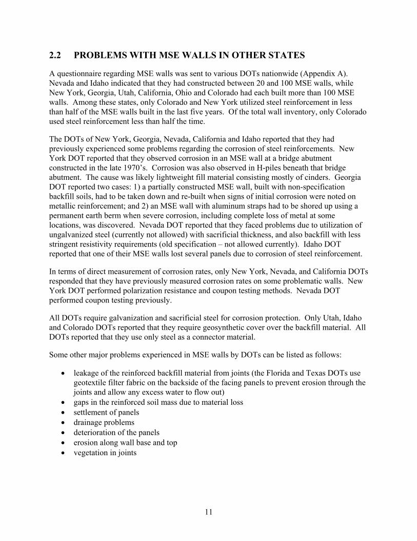
Some other major problems experienced in MSE walls by DOTs can be listed as follows:
• leakage of the reinforced backfill material from joints (the Florida and Texas DOTs use geotextile filter fabric on the backside of the facing panels to prevent erosion through the joints and allow any excess water to flow out)
• gaps in the reinforced soil mass due to material loss • settlement of panels • drainage problems • deterioration of the panels • erosion along wall base and top • vegetation in joints
11
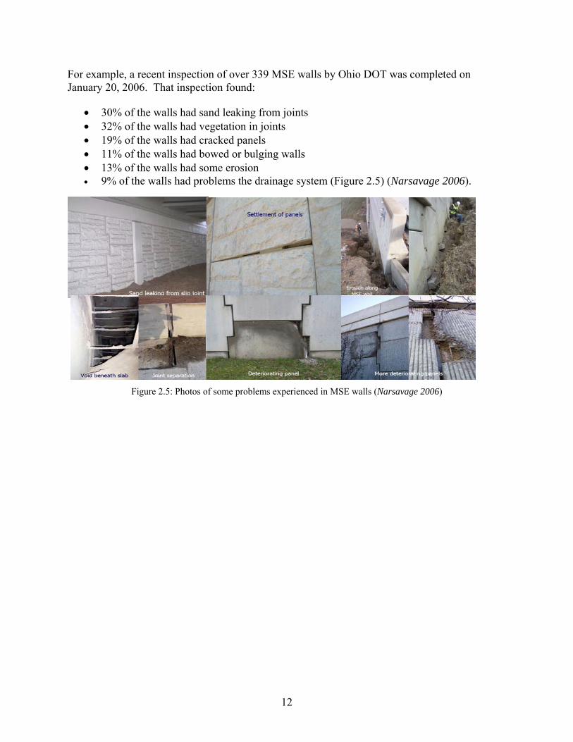
For example, a recent inspection of over 339 MSE walls by Ohio DOT was completed on January 20, 2006. That inspection found:
• 30% of the walls had sand leaking from joints • 32% of the walls had vegetation in joints • 19% of the walls had cracked panels • 11% of the walls had bowed or bulging walls • 13% of the walls had some erosion • 9% of the walls had problems the drainage system (Figure 2.5) (Narsavage 2006).
Figure 2.5: Photos of some problems experienced in MSE walls (Narsavage 2006)
12
3.0 REINFORCEMENT CORROSION
The Federal Highway Administration has characterized potentially corrosive environments into three categories for the United States Department of Transportation; geological, stray currents and other environmental factors. Potentially corrosive geological environments are usually identified as being highly acidic, alkaline, or found in areas with high amounts of organic matter (Elias 2000). Stray currents may be an additional source of corrosion for MSE systems that are constructed near electrically powered rail systems or other systems which could discharge current in the vicinity of the walls. Stray currents are only a concern for structures built within 30 to 60 meters from the source. AASHTO recommends that a corrosion expert evaluate the hazard and possible mitigating features when within this range (Elias 2000). Other environmental factors that FHWA identified to have an effect on corrosion rates for MSE walls were soil compaction, and moisture content. When soil compaction is completed evenly, soil resistivity is consistent, decreasing corrosivity. For mild steel, the rate of corrosion increases when the moisture content exceeds 50% of saturation. It is imperative to have free draining backfills or drainage systems in place to keep moisture contents down below the 25% saturation range for MSE walls. Backfill moisture contents greater than 25 to 40% increase the rate of general corrosion (Elias 2000).
3.1 CORROSION DETECTION
The two major aspects of corrosion inspection capability are detection and characterization. Detection is the overall ability of the technique to discriminate between relevant and non-relevant corrosion indicators. Characterization, in contrast, is the capacity of a technique to define the source of the deterioration once it has been detected. Both destructive and nondestructive techniques for corrosion detection exist. Challenges exist with both types of inspection techniques (Clark 1990). It should be standard practice to include durability testing samples in each MSE wall constructed. The inclusion of durability testing samples would eliminate the problems associated with destructive testing while at the same time providing some of the benefits of destructive testing.
3.1.1 Destructive Testing Methods
Exhumation of a wall is the most basic destructive technique used to attain metal loss data. This involves exhuming and examining samples of reinforcements for evidence of corrosion, including loss of cross section. The limitations of this technique are:
1) It is limited to reinforcements that are accessible and usually near the surface of the structure. This is not necessarily the most corrosive area of the reinforced wall backfill mass.
2) Corrosion rates are established through weight loss and thickness measurements, which require that the original thickness and weights be known exactly. This is a potential
13

problem if, during construction, a contractor substituted alternate materials, albeit approved, that had greater thickness of either the base metal or the corrosion protection material.
3) Since corrosion rate is known to decay with time, multiple measurements should be made at different times to assess the effect of time on the rate of metal loss (Gladstone 2006).
3.1.2 Non-Destructive Techniques
Non-destructive testing methods, such as polarization resistance measurements and linear polarization resistance measurements, are used to obtain instantaneous in-situ average corrosion rates. Applying the obtained rates will provide an average corrosion rate for the entire reinforcement element in its stressed state. Measurements can be taken at any time in order to monitor performance more closely (Elias 2000). Other non-destructive techniques include coupon testing, half-cell potential measurements of reinforcements, and the use of sacrificial straps, which must be installed during the construction of the wall (Bastick 1992; and Gladstone 2000).
For the implementation of electrochemical methods on existing walls, potential measurements of representative reinforcements must be made first to establish the average composition of the surface of the reinforcement. With this being required, there is a need for accurate data on the type of strips that were used in the existing wall. If this is unavailable, then a baseline for the electrochemical data collected could not be met, rendering this method useless. When the strip data is available, several steps must be followed to determine corrosion rates through polarization resistance. The geometry of the exposed area of the component to be analyzed must be known or estimated accurately. This should not be an issue since the geometry of reinforcing strips in MSE structures is generally well defined. When calculating the polarization resistance of the reinforcing strip, ohmic resistance should be filtered out. The resistance of the soil should be filtered (subtracted) from that of the polarization resistance with one of several available methods. Conversion values required to convert the polarization resistance to a corrosion rate must be known. Conversion constants usually will range between 0.020 and 0.050 for galvanized steel. Also, the current composition of the surface being analyzed (i.e. galvanized or bare steel) should be known. Corrosion potential monitoring can be used to determine metal phases as the reinforcement loses zinc, ultimately down to the carbon steel base (Elias 2000).
Linear polarization resistance (LPR) measurements can be used to attain an instantaneous corrosion rate. Corrosion history cannot be determined from a single measurement, therefore, the reinforcement condition is difficult to determine from isolated LPR measurements. LPR is best utilized when measurements are taken throughout the lifetime of the structure, determining a relationship between time and corrosion rate. For older structures it is difficult to interpret what LPR measurements mean, especially if the existing conditions are unknown. Since corrosion rates vary throughout the year, measurements should be taken during different seasons to attain an average corrosion rate for the structure (Gladstone 2006).
Another non-destructive testing method, which can be installed during construction of MSE walls, is the implementation of coupon testing and half-cell potential measurements of reinforcements at regular intervals. The North Carolina Department of Transportation began
14
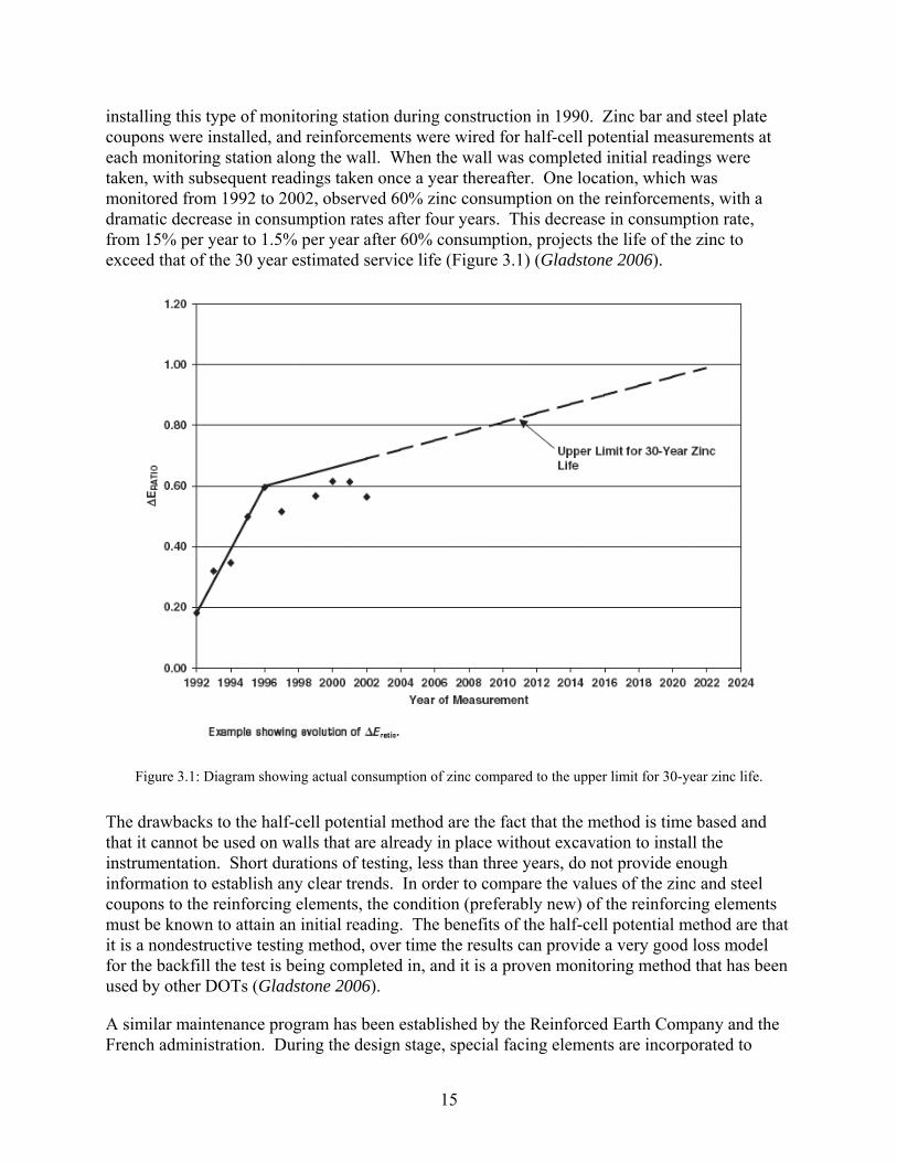
installing this type of monitoring station during construction in 1990. Zinc bar and steel plate coupons were installed, and reinforcements were wired for half-cell potential measurements at each monitoring station along the wall. When the wall was completed initial readings were taken, with subsequent readings taken once a year thereafter. One location, which was monitored from 1992 to 2002, observed 60% zinc consumption on the reinforcements, with a dramatic decrease in consumption rates after four years. This decrease in consumption rate, from 15% per year to 1.5% per year after 60% consumption, projects the life of the zinc to exceed that of the 30 year estimated service life (Figure 3.1) (Gladstone 2006).
Figure 3.1: Diagram showing actual consumption of zinc compared to the upper limit for 30-year zinc life.
The drawbacks to the half-cell potential method are the fact that the method is time based and that it cannot be used on walls that are already in place without excavation to install the instrumentation. Short durations of testing, less than three years, do not provide enough information to establish any clear trends. In order to compare the values of the zinc and steel coupons to the reinforcing elements, the condition (preferably new) of the reinforcing elements must be known to attain an initial reading. The benefits of the half-cell potential method are that it is a nondestructive testing method, over time the results can provide a very good loss model for the backfill the test is being completed in, and it is a proven monitoring method that has been used by other DOTs (Gladstone 2006).
A similar maintenance program has been established by the Reinforced Earth Company and the French administration. During the design stage, special facing elements are incorporated to
15

house durability samples. The durability samples are made out of a standard reinforcing strip, taken from the stock of the finished product, which will be used to complete the structure. The strip is cut in one meter pieces. One of these pieces will be used to make a full set of tests to precisely identify the characteristics of the strip (and of the durability sample) in its original state. If the strip piece is galvanized, the thickness of the zinc coating is measured by dissolution. In all cases a tensile rupture test is performed. A minimum of two such panels, or eight durability samples, is installed in each structure. The number of samples is increased for large structures. Care is taken in the design phase to position these samples in the most unfavorable location in the wall (i.e. below a low point of the road vertical alignment or where incoming water or deficient drainage is to be expected). Corrosion is monitored through the durability sample method. A first sample (or series of samples when the structure includes more than eight) is retrieved after 10 years and other samples are normally retrieved every 15 years. When each sample is taken out of the structure it is brushed, cleaned, and weighed. The remaining zinc left on the strip is then determined and the loss thickness is plotted against the expected loss thickness versus time (Bastick 1992). If the actual loss in thickness is less than expected, the next sample might not be retrieved until more than 15 years and the service life of the structure may eventually be increased. If the loss is very close to the expected loss then the next sample should be retrieved at 15 years. In the event the loss exceeds that of what was expected, then the next sample should be retrieved in less than 15 years and remedial action should be taken if necessary (Bastick 1992).
Terre Armee Internationale (TAI) has been conducting research on MSE walls since 1970 with the goal of confirming prior findings. Three main modes of experimentation are being conducted: box tests, laboratory tests, and full scale wall tests. All of which focus on the cause and effect of corrosion on MSE walls. Findings have yielded favorable results to which standards can be adjusted and monitoring programs can be established (Bastick 1992).
Through TAI’s research it has been determined that corrosion rates are dependent upon five individual soil parameters:
1. Water content - soil water contains the salts and constitutes the electrolyte necessary for corrosion
2. Soil resistivity, when measured at saturation, gives a figure related to the total amount of salts present in the soil
3. pH (potential of hydrogen), that governs the solubility of corrosion by-products and thus the buildup of protective layers around the buried metal
4. Chloride content – chloride is the most common aggressive salt 5. Sulfate content
TAI has also validated that the behavior law of corrosion for galvanized steel can be used to estimate the average thickness loss of metal with time relative to the aggressiveness of the soil (Equation 3-1).
P = A•T n (3-1)
16
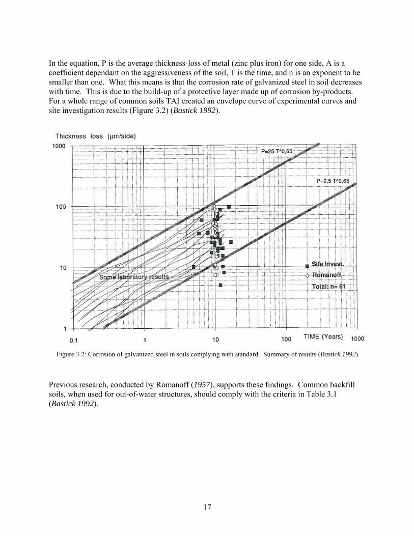
In the equation, P is the average thickness-loss of metal (zinc plus iron) for one side, A is a coefficient dependant on the aggressiveness of the soil, T is the time, and n is an exponent to be smaller than one. What this means is that the corrosion rate of galvanized steel in soil decreases with time. This is due to the build-up of a protective layer made up of corrosion by-products. For a whole range of common soils TAI created an envelope curve of experimental curves and site investigation results (Figure 3.2) (Bastick 1992).
Figure 3.2: Corrosion of galvanized steel in soils complying with standard. Summary of results (Bastick 1992)
Previous research, conducted by Romanoff (1957), supports these findings. Common backfill soils, when used for out-of-water structures, should comply with the criteria in Table 3.1 (Bastick 1992).
17
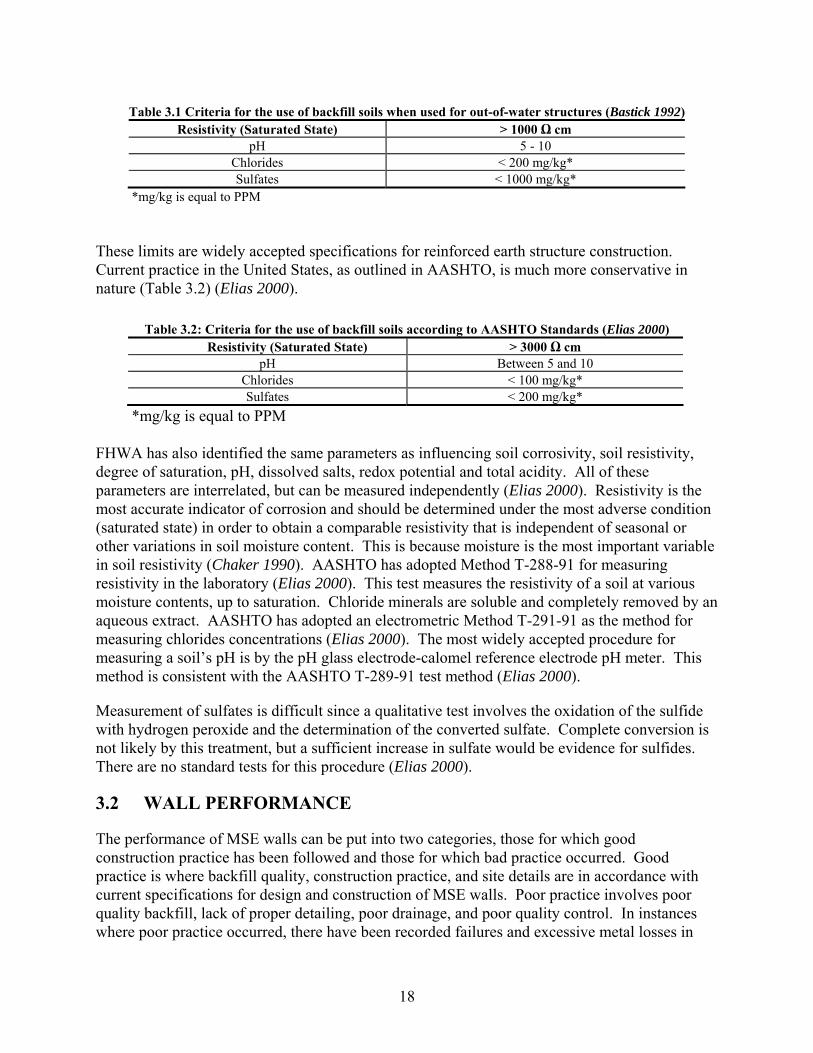
Table 3.1 Criteria for the use of backfill soils when used for out-of-water structures (Bastick 1992) Resistivity (Saturated State) > 1000 Ω cm
pH 5 - 10 Chlorides < 200 mg/kg* Sulfates < 1000 mg/kg*
*mg/kg is equal to PPM These limits are widely accepted specifications for reinforced earth structure construction. Current practice in the United States, as outlined in AASHTO, is much more conservative in nature (Table 3.2) (Elias 2000).
Table 3.2: Criteria for the use of backfill soils according to AASHTO Standards (Elias 2000) Resistivity (Saturated State) > 3000 Ω cm
pH Between 5 and 10 Chlorides < 100 mg/kg* Sulfates < 200 mg/kg*
*mg/kg is equal to PPM FHWA has also identified the same parameters as influencing soil corrosivity, soil resistivity, degree of saturation, pH, dissolved salts, redox potential and total acidity. All of these parameters are interrelated, but can be measured independently (Elias 2000). Resistivity is the most accurate indicator of corrosion and should be determined under the most adverse condition (saturated state) in order to obtain a comparable resistivity that is independent of seasonal or other variations in soil moisture content. This is because moisture is the most important variable in soil resistivity (Chaker 1990). AASHTO has adopted Method T-288-91 for measuring resistivity in the laboratory (Elias 2000). This test measures the resistivity of a soil at various moisture contents, up to saturation. Chloride minerals are soluble and completely removed by an aqueous extract. AASHTO has adopted an electrometric Method T-291-91 as the method for measuring chlorides concentrations (Elias 2000). The most widely accepted procedure for measuring a soil’s pH is by the pH glass electrode-calomel reference electrode pH meter. This method is consistent with the AASHTO T-289-91 test method (Elias 2000).
Measurement of sulfates is difficult since a qualitative test involves the oxidation of the sulfide with hydrogen peroxide and the determination of the converted sulfate. Complete conversion is not likely by this treatment, but a sufficient increase in sulfate would be evidence for sulfides. There are no standard tests for this procedure (Elias 2000).
3.2 WALL PERFORMANCE
The performance of MSE walls can be put into two categories, those for which good construction practice has been followed and those for which bad practice occurred. Good practice is where backfill quality, construction practice, and site details are in accordance with current specifications for design and construction of MSE walls. Poor practice involves poor quality backfill, lack of proper detailing, poor drainage, and poor quality control. In instances where poor practice occurred, there have been recorded failures and excessive metal losses in
18

MSE walls due to the corrosive environments created by poor practice or adverse site conditions (Gladstone 2006). As long as good practice is followed during the construction of MSE walls, the risk of corrosion induced problems is very minimal, especially in the U.S. where our standards are considered conservative in comparison to other nations.
19

20
4.0 ODOT MSE WALL ELECTRONIC DATABASE
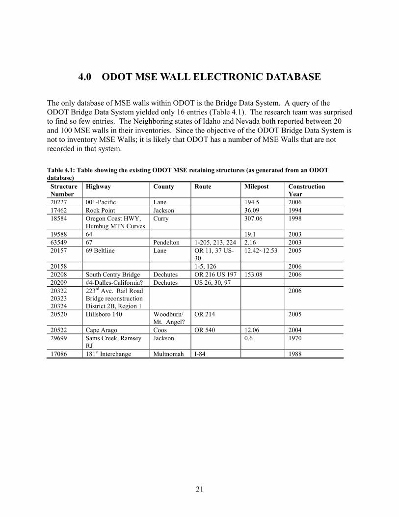
The only database of MSE walls within ODOT is the Bridge Data System. A query of the ODOT Bridge Data System yielded only 16 entries (Table 4.1). The research team was surprised to find so few entries. The Neighboring states of Idaho and Nevada both reported between 20 and 100 MSE walls in their inventories. Since the objective of the ODOT Bridge Data System is not to inventory MSE Walls; it is likely that ODOT has a number of MSE Walls that are not recorded in that system. Table 4.1: Table showing the existing ODOT MSE retaining structures (as generated from an ODOT database)
Structure Number
Highway County Route Milepost Construction Year
20227 001-Pacific Lane 194.5 2006 17462 Rock Point Jackson 36.09 1994 18584 Oregon Coast HWY,
Humbug MTN Curves Curry 307.06 1998
19588 64 19.1 2003 63549 67 Pendelton 1-205, 213, 224 2.16 2003 20157 69 Beltline Lane OR 11, 37 US-
30 12.42~12.53 2005
20158 1-5, 126 2006 20208 South Centry Bridge Dechutes OR 216 US 197 153.08 2006 20209 #4-Dalles-California? Dechutes US 26, 30, 97 20322 20323 20324
223rd Ave. Rail Road Bridge reconstruction District 2B, Region 1
2006
20520 Hillsboro 140 Woodburn/Mt. Angel?
OR 214 2005
20522 Cape Arago Coos OR 540 12.06 2004 29699 Sams Creek, Ramsey
RJ Jackson 0.6 1970
17086 181st Interchange Multnomah I-84 1988
21

22
5.0 REFERENCES
Abu-Hejleh, N., McMullen, M., Hearn, G., Zornberg, J. Design and Construction Guidelines for MSE Walls with Independent Full Height Facing Panels. Publication CDOT-DTD-R- 2001-5. California Department of Transportation, 2001. AMSE. Reduced Zinc Loss Rate for Design of MSE Structures: A White Paper and Proposal to Change the Metal Loss Model in the AASHTO Specifications for Design ff MSE Walls. Association for Metallically Stabilized Earth (http://amsewalls.org/AMSE_Metal_Loss_ White_Paper.pdf ). 2006. Bastick, M.J., and Jailloux, J.M. Twenty-Five Years of Corrosion Control in Reinforced Earth Structures. Earth Reinforcement Practice, Vol. 1, 1992, pp. 17-22. Caltrans Bridge Design Specifications. Section 5: Retaining Walls. California Department of Transportation, (http://www.dot.ca.gov/hq/esc/techpubs/manual/bridgemanuals/bridge-design- specifications/B-B-specs.htm). 2004. Chaker, Victor. Corrosion Testing in Soils – Past, Present, and Future. Corrosion Testing and Evaluation: Silver Anniversary Volume, Astim Stp 1000, 1990, pp. 95-111. Clark, William G., Jr. and Metala, M.J. The Nondestructive Characterization of Corrosion. Corrosion Testing and Evaluation: Silver Anniversary Volume, ASTM STP 1000, 1990, pp. 39-49. Elias, V. Corrosion/Degradation of Soil Reinforcements for Mechanically Stabilized Earth Walls and Reinforced Soil Slopes. Publication FHWA-NHI-00-044. FHWA, U.S. Department of Transportation, 2000. Elias, V., Christopher, B. R., Berg, R.R. Mechanically Stabilized Earth Walls and Reinforced Soil Slopes Design and Construction Guidelines. Publication FHWA-NHI-00-043. FHWA, U.S. Department of Transportation, 2001. Gladstone, R. A., Anderson, P. L., Fishman, K. L., Withiam, J. L. Durability of Galvanized Soil Reinforcement, More Than 30 Years of Experience with Mechanically Stabilized Earth. Transportation Research Record, No 1975, 2006, pp. 49-59. Koerner, R. M. Designing with Geosynthetics. Prentice Hall; 4th Edition, 1998. McGee, P.E. Reinforced Earth Wall Strip Serviceability Study. Final Report, Publication GDOT Special Research Study, No. 8405. Georgia Department of Transportation, 1985.
23
24
Narsavage, P. MSE Walls, Problems and Solutions. Publication Ohio Department of Transportation Geotechnical Workshop, 2006 ODOT Specifications. Oregon Department of Transportation, Section 00596.11. Oregon Department of Transportation, 2007. Romanoff, M., Underground Corrosion, National Bureau of Standards Circular 579, Department of Commerce, National Bureau of Standards, April 1557. Rowe, Kerry R. and Ho, S.K. Keynote Lecture: A Review of the Behavior of Reinforced Soil Walls. Geotechnical Research Centre, University of Western Ontario, London, Ont., 1993, pp. 801-830. Vulova, C., Leshchinsky, D. Effects of Geosynthetic Reinforcement Spacing on the Performance of Mechanically Stabilized Earth Walls. Publication FHWA-RD-03-048 (http://www.fhwa.dot.gov/engineering/geotech/pubs/03048). FHWA, U.S. Department of Transportation, 2003.

APPENDIX A: STATE DOT QUESTIONNAIRE AND RESULTS


1.) How many MSE retaining walls has your DOT built so far? a. None b. Less than 20 c. Between 20 and 100 (NV, ID) d. More than 100 (NY (about 250), GA, UT, CA, OH (about 300), CO) (If you know the approximate number, please mention)
1) Approximately how much percent of the MSE walls that have been constructed in the last 5
years is steel reinforced? a. 0% b. 100% (NV) c. 0-20% (CO) d. 20-50% (NY) e. 50-80% (UT) f. 80-100% (GA, OH, ID)
2) What is the approximate percentage of total MSE walls in your DOT’s inventory that use
steel reinforcing? a. 100% (NV) b. Less than 20% (CO) c. 20-50% d. 50-80% (UT) e. 80-100% (NY, GA, OH, ID)
3) Which types of metallic reinforcement has been used in MSE walls? (please check all that
apply) a. metal strips (NY, GA, UT, CA, OH, NV, ID, CO) b. grids (NY, UT, CA, OH, NV, ID) c. wire mesh (GA, OH, NV, ID)
4) Which of the following problems in general have your DOT experienced, if any? (please
check all that apply) a. settlement of panels (NY, GA, UT, OH) b. leakage of the reinforced backfill material from joints (NY, UT, OH, NV, ID) c. deterioration of the panels (UT, OH, CO) d. erosion along wall base and top (GA, OH, ID) e. gaps through the reinforced soil mass due to material loss (OH) f. vegetation in joints (NY, GA, OH, ID)
5) Has your DOT experienced any problems regarding the corrosion of the steel
reinforcements? a. No (UT, OH, CO) b. Yes (Please indicate some if possible) (CA)
A-1
NY: We constructed a wall in the late 1970’s that was backfilled with lightweight fill. Unfortunately, the fill was mostly cinders, which had a corrosive effect not only on the MSE straps but also severely corroded the H-piles beneath the bridge abutment. Other than that, we have had satisfactory performance from our steel reinforcements. GA: 1. A partially constructed MSE wall built with non-specification backfill soils had to be taken down and re-built when signs of initial corrosion were noted on metal straps. 2. A second MSE wall using aluminum straps had to be shored up using a permanent earth berm when severe corrosion including complete loss of metal at some locations was discovered. NV: Problems were due to use of ungalvanized steel w/ sacrificial steel (not allowed currently) and the use of backfill material with less stringent resistivity requirements (old specification – not allowed currently). ID: One wall lost several panels due to corrosion of steel reinforcement 6) Have you directly measured any corrosion rates of metallic reinforcement on any walls?
a. No (GA, UT, OH, ID, CO) b. Yes, with Polarization Resistance Monitor (NY) c. Yes, with sacrificial steel methods d. Yes, with coupon testing (NY, NV used only on problematic walls) e. Yes, with ultrasonic monitoring systems f. Yes, others (please indicate the method)
NY: Along with PR testing, we measure the electrochemical potential of the straps against a known electrode to determine whether the zinc coating or the steel strap is in primary contact with the soil. CA: Responded to the question yes, however did not mention the method 7) Does your DOT require any specific precautions for the contractors regarding corrosion
protection (please check all that apply). a. No b. Yes, galvanization (NY, GA, UT, CA, OH, NV, ID, CO) c. Yes, sacrificial steel (NY, GA, UT, CA, OH, ID, CO) d. Yes, epoxy coating e. Yes, polymer coating f. Yes, using geosynthetic over the backfill material (UT, ID, CO)
A-2

8.) Which type of connectors are you using a. Metallic, steel (NY, GA, UT, OH, NV, ID, CO ) b. Metallic, other alloy c. Other (please indicate the type)
9.) Does your DOT have any specifications available regarding the design of reinforcements,
type of backfill material to be used in MSE walls? a. No b. Yes (Please email it to us, if possible) (OH, ID, CO)
NY: Section 554 of our Standard Specs: is available at https://www.nysdot.gov/portal/page/portal/main/businesscenter/engineering/specifications/specs-repository/sec551to554_p5-41to58.pdf GA: http://tomcat2.dot.state.ga.us/thesource/pdf/specs/ss626.html OH: http://www.dot.state.oh.us/construction/OCA/Specs/SSandPN2005/840_07212006_for_2005.PDF NV: Information available on FHWA National Specficication website or NDOT website regarding material properties. See section 640 of the specifications. Additional Comments: OH: Within the last two years, Ohio DOT has started inspecting our MSE walls and noticing numerous problems with them. To address these problems, we have recently made changes to our MSE wall design requirements and created a new construction specification. I gave a presentation on these changes at a recent conference in Columbus, Ohio. You can view my presentation at the following website: http://www.dot.state.oh.us/se/MSEWALLS/MSEWALLS.htm. My presentation is the one titled "ODOT Design & Construction Requirements for MSE Walls (OTEC)". Also on this page are other presentations about MSE walls made by ODOT engineers.
A-3
A-4
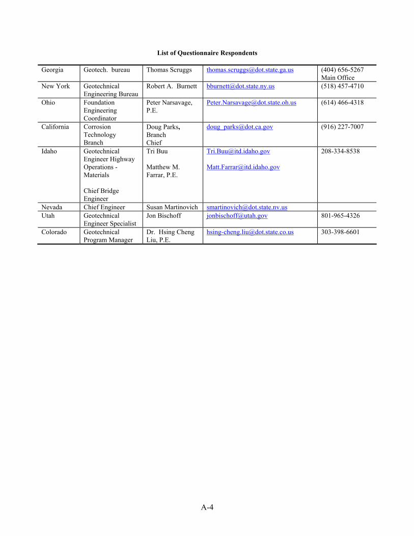
List of Questionnaire Respondents
Georgia Geotech. bureau Thomas Scruggs [email protected] (404) 656-5267 Main Office
New York Geotechnical Engineering Bureau
Robert A. Burnett [email protected] (518) 457-4710
Ohio Foundation Engineering Coordinator
Peter Narsavage, P.E.
[email protected] (614) 466-4318
California Corrosion Technology Branch
Doug Parks, Branch Chief
[email protected] (916) 227-7007
Idaho Geotechnical Engineer Highway Operations - Materials Chief Bridge Engineer
Tri Buu Matthew M. Farrar, P.E.
[email protected] [email protected]
208-334-8538
Nevada Chief Engineer Susan Martinovich [email protected] Utah Geotechnical
Engineer Specialist Jon Bischoff [email protected] 801-965-4326
Colorado Geotechnical Program Manager
Dr. Hsing Cheng Liu, P.E.
[email protected] 303-398-6601
