evaluation of fire-fighting helmet surface technology for high radiant heat applications
TRANSCRIPT

University of KentuckyUKnowledge
University of Kentucky Master's Theses Graduate School
2003
EVALUATION OF FIRE-FIGHTING HELMETSURFACE TECHNOLOGY FOR HIGHRADIANT HEAT APPLICATIONSDavid L. BarnettUniversity of Kentucky, [email protected]
Click here to let us know how access to this document benefits you.
This Thesis is brought to you for free and open access by the Graduate School at UKnowledge. It has been accepted for inclusion in University ofKentucky Master's Theses by an authorized administrator of UKnowledge. For more information, please contact [email protected].
Recommended CitationBarnett, David L., "EVALUATION OF FIRE-FIGHTING HELMET SURFACE TECHNOLOGY FOR HIGH RADIANT HEATAPPLICATIONS" (2003). University of Kentucky Master's Theses. 305.https://uknowledge.uky.edu/gradschool_theses/305

ABSTRACT OF THESIS
EVALUATION OF FIRE-FIGHTING HELMET SURFACE TECHNOLOGY FOR HIGH RADIANT HEAT APPLICATIONS
Protective helmets used by fire-fighters must be designed to minimize the amount of heat transferred to the user’s head while providing durability, comfort, and affordable costs. This thesis highlights the evaluation of new helmet technology specifically tailored to high radiant heat environments to advance the state-of-the-art in head protection for this application. The research focused on the assessment of the outer shells of helmets and the properties of the surfaces. The development included the evaluation of radiation heat transfer, in a laboratory environment, to various helmet shell surface constructions. Industry standards were considered, and critiqued. Experiments were designed to isolate critical design variables for measurement and evaluation. Custom, purpose-built laboratory apparatus for testing helmets were designed, explained and utilized in the testing of specimens. Additionally, market demands for fire-fighting helmets were explored. Helmet durability was specifically addressed with abrasion criteria established and the reflectivity effects of the abraded surfaces evaluated. Resulting from this study, new surface technologies were identified for possible development in future helmet designs. Various surface materials, finishes, and coatings were compared and contrasted to current industry state-of-the-art equipment. The knowledge discovered further advanced modern head protection science in aim of increased safety and performance of fire-fighting personnel. KEYWORDS: Coatings, Fire-Fighting, Helmet, Radiant Heat, Radiation MULTIMEDIA ELEMENT USED: Microsoft Audio Video Interleaved (.avi)
David L. Barnett 2003
Copyright � David L. Barnett 2003

EVALUATION OF FIRE-FIGHTING HELMET SURFACE TECHNOLOGY FOR HIGH RADIANT HEAT APPLICATIONS
By
David Louis Barnett, P.E.
Dr. Pinar Menguc Director of Thesis
Dr. George Huang Director of Graduate Studies
2003

RULES FOR THE USE OF THESES
Unpublished theses submitted for the Master’s degree and deposited in the University of
Kentucky Library are as a rule open for inspection, but are to be used only with due regard to the
rights of the authors. Bibliographical references may be noted, but quotations or summaries of
parts may be published only with the permission of the author, and with the usual scholarly
acknowledgements.
Extensive copying or publication of the thesis in whole or in part also requires the consent of the
Dean of the Graduate School of the University of Kentucky.

THESIS
David Louis Barnett, P.E.
The Graduate School
University of Kentucky
2003

EVALUATION OF FIRE-FIGHTING HELMET SURFACE TECHNOLOGY FOR HIGH RADIANT HEAT APPLICATIONS
_______________________________
THESIS _______________________________
A thesis submitted in partial fulfillment of the requirements for the degree of Master of Science
in Mechanical Engineering in the College of Engineering at the University of Kentucky
By
David Louis Barnett, P.E.
Director: Dr. Pinar Menguc, Professor of Mechanical Engineering
Lexington, Kentucky
2003
Copyright © David L. Barnett 2003

DEDICATION
This thesis is dedicated to my loving parents, Emmett and Karen Barnett. God has blessed me in
many ways and perhaps His greatest blessing has been my family. Their faithful support and
unconditional love has encouraged me throughout my life. Physically, emotionally, and
spiritually, my mother and father have always provided for my every need, exhibiting the love of
Christ. Their profound impact on my life will never be fully appreciated.

ACKNOWLEDGEMENTS
This thesis was made possible by the gracious contributions of many individuals to whom I owe
much gratitude. My research advisors, Dr. Pinar Menguc and Dr. Kozo Saito, provide priceless
guidance, advice, and constructive criticism throughout my Master’s degree pursuit at the
University of Kentucky. Their direction optimized my educational experience and kept my
studies focused and effective.
I would also like to thank my managers and co-workers at the E.D. Bullard Company for
allowing my educational pursuit, supporting my research, and flexibly adapting to my work
schedule. Much gratitude is also due to the many industrial firms that provided technical
support, plating services, and experimental equipment. I believe that the synergy resulting from
cooperation between academia and industry afforded great benefits to everyone involved.
Perhaps most importantly, I would like to thank my Christian brothers and sisters for keeping me
ever mindful that education is a blessing and that “to whom much is given much is required”.
My Christian friends and mentors have encouraged me throughout my studies, keeping me
focused on the One who made it all possible.
iii

TABLE OF CONTENTS
Acknowledgements ……………………………………………………..………………………. iii
List of Tables ………………………………………………………………………..…………....vi
List of Figures ………………………………………………………………………..…………. vii
List of Files ………………………………………………………………………...…..…….….. ix
Nomenclature ………………………………………………………….………………..……..… x
Chapter I: Introduction ............................................................................................................... 1
1.1: Background ………………………………………………………………………… 1
1.2: Industry Standards …..……….…………....…………………....…………….……. 1
1.3: Current State-of-the-Art ………………………………………………….……...… 2
1.4: Research Challenge …………………………………………………….…………. 2
Chapter II: Product Design ......................................................................................................... 6
2.1: Helmet Design Considerations ………………………………………………..…… 6
2.2: ARFF Helmet Design Peculiarities …………………………….………………..… 7
2.3: Shortcomings of Current ARFF Shrouds ………………………………..………… 8
2.4: Performance Criteria …………………………………………….………………… 9
2.5: Technology Advancement ……………………………………………..…….…… 10
Chapter III: Methodology/Experimentation ............................................................................ 13
3.1: Experimental Objectives .......................................................................….….......... 13
3.2: Test Apparatus ......................................................................................................... 13
3.3: Radiant Heat Source ........................................................................................….... 13
3.4: Rolling Test Fixture ......................................................................................…....... 14
3.5: Temperature Measurement ...........................................................................…....... 15
3.6: Radiant Heat Flux Measurement .................................................................…........ 16
3.7: Data Acquisition ......................................................................................…............ 17
3.8: Rationale for Methodology ...................................................................…............... 18
3.9: Abrasive Conditioning .............................................................................…............ 18
3.10: Abrasion Effects ...................................................................................................... 20
3.11: Test Specimens ........................................................................................................ 21
iv

v
Chapter IV: Theoretical Considerations and Modeling ......................................................... 31
4.1: Literature Search ..................................................................................................... 31
4.2: Fire Science Summary ............................................................................................ 31
4.3: Surface Properties ................................................................................................... 33
4.4: Analytical Modeling ................................................................................................ 34
4.5: Constant Heat Flux Model ...................................................................................... 35
4.6: Radiant Heat Transfer Model .................................................................................. 37
4.7: Spectral Emissivity .................................................................................................. 40
4.8: Comparison of Radiant Heater to Open Fire ........................................................... 43
Chapter V: Experimental Discussion & Analysis .................................................................... 46
5.1: Observations ............................................................................................................ 46
5.2: Potential Sources of Error ....................................................................................... 48
5.3: Discussion of Findings ............................................................................................ 50
Chapter VI: Conclusions & Future Work ............................................................................... 63
6.1: Establishment of Test Methods ............................................................................... 63
6.2: Performance of Test Specimens .............................................................................. 64
6.3: Benchmarks for Future Research ............................................................................ 65
6.4: Exploration of New Technology ............................................................................. 66
6.5: Refinement & Extension of Experiments ............................................................... 68
6.6: Final Remarks ......................................................................................................... 69
Appendix A: Experimental Data .................................................................................................. 70
Appendix B: Experimental Test Specimen Photographs ............................................................. 80
Appendix C: Abraded Experimental Test Specimen Photographs ............................................... 90
Bibliography ............................................................................................................................... 100
Vita ............................................................................................................................................. 102

LIST OF TABLES
Table 5.1: Average Temperatures for Unabraded Shells .......................................................... 55
Table 5.2: Average Temperatures for Abraded Shells ............................................................. 56
Table 5.3: Abrasion Effects ...................................................................................................... 57
Table 5.4: Shell Masses ............................................................................................................ 60
Table 5.5: Unabraded Spectral Effects ..................................................................................... 61
Table 5.6: Abraded Spectral Effects ........................................................................................ 62
Table A1.1: Experimental Results for Uncoated White Shell .................................................... 71
Table A1.2: Experimental Results for Titanium Metalized Shell ............................................... 72
Table A1.3: Experimental Results for Copper Metalized Shell .................................................. 73
Table A1.4: Experimental Results for Pewter Coated Shell ....................................................... 74
Table A1.5: Experimental Results for Aluminum Painted Shell ................................................ 75
Table A1.6: Experimental Results for Aluminum Metalized Shell ............................................ 76
Table A1.7: Experimental Results for Aluminum Sputtered Shell ............................................. 77
Table A1.8: Experimental Results for Nickel-Chrome Electroplated Shell ............................... 78
Table A1.9: Experimental Results for Aluminized Shroud Covered Shell ................................. 79
vi

LIST OF FIGURES
Figure 1.1: Typical ARFF Personnel and Equipment .................................................................. 4
Figure 1.2: Typical ARFF Helmet with Faceshield and Ear/Neck Protector .............................. 5
Figure 2.1: Thermoplastic Helmet Shell After Exposure to High Radiant Heat ........................ 12
Figure 3.1: Schematic of Radiant Heat Exposure Test .............................................................. 22
Figure 3.2: Experimental Test Apparatus Disengaged .............................................................. 23
Figure 3.3: Experimental Test Apparatus Engaged ................................................................... 24
Figure 3.4: Radiant Heater ......................................................................................................... 25
Figure 3.5: Rolling Test Fixture ................................................................................................. 26
Figure 3.6: Helmet Shell Mounting Block ................................................................................. 27
Figure 3.7: Radiometer in Metalized Helmet Shell ................................................................... 28
Figure 3.8: Abrasion Apparatus (with Animation) .................................................................... 29
Figure 3.9: Abrasive Block and Vertical Air Cylinder .............................................................. 30
Figure 4.1: Heat Flux Model Schematic .................................................................................... 35
Figure 4.2: Radiant Model Schematic ....................................................................................... 37
Figure 4.3: View Factor Catalog Solution ................................................................................. 38
Figure 4.4: Spectral Emissive Power ......................................................................................... 45
Figure 5.1: Average Temperature Profiles for Unabraded Shells ............................................. 55
Figure 5.2: Average Temperature Profiles for Abraded Shells ................................................. 56
Figure 5.3: Bubble Helmet Shell Surface on Stock White Thermoplastic Shell ....................... 58
Figure 5.4: Cross Section of Bubbled Helmet Shell .................................................................. 59
Figure B.1: Stock White Thermoplastic Helmet Shell ............................................................... 81
Figure B.2: Titanium Metalized Helmet Shell ........................................................................... 82
Figure B.3: Electroless Copper Plated Helmet Shell ................................................................. 83
Figure B.4: Pewter Coated Helmet Shell ................................................................................... 84
Figure B.5: Aluminum Painted Helmet Shell ............................................................................ 85
Figure B.6: Aluminum Vacuum Metalized Helmet Shell .......................................................... 86
Figure B.7: Aluminum Sputtered Helmet Shell ......................................................................... 87
Figure B.8: Nickel-Chrome Electroplated Helmet Shell ........................................................... 88
Figure B.9: Aluminized Textile Shroud Covered Helmet Shell ................................................ 89
vii
viii
Figure C.1: Abraded Stock White Thermoplastic Helmet Shell ................................................ 91
Figure C.2: Abraded Titanium Metalized Helmet Shell ............................................................ 92
Figure C.3: Abraded Electroless Copper Plated Helmet Shell .................................................. 93
Figure C.4: Abraded Pewter Coated Helmet Shell .................................................................... 94
Figure C.5: Abraded Aluminum Painted Helmet Shell ............................................................. 95
Figure C.6: Abraded Aluminum Vacuum Metalized Helmet Shell ........................................... 96
Figure C.7: Abraded Aluminum Sputtered Helmet Shell .......................................................... 97
Figure C.8: Abraded Nickel-Chrome Electroplated Helmet Shell ............................................ 98
Figure C.9: Abraded Aluminized Textile Shroud Covered Helmet Shell ................................. 99

LIST OF FILES
dbarnett.pdf ............................................................................................................ 5.22 MB
abrasion.avi ............................................................................................................ 5.38 MB
ix

NOMENCLATURE
SYMBOLS (UNITS):
cp = heat capacity (kJ/kg.K)
d = shell thickness (m or mm)
E = emissive power (W/cm2)
F = view factor
G = Irradiation (W/cm2)
H = distance from heater surface to shell
element (m)
k = thermal conductivity (W/m��C)
Q = heat (W)
Q” = heat flux (W/m2 or W/cm2)
T = Temperature (�C or K)
� = absorptivity
� = emissivity
� = thermal diffusivity (m2/s)
� = wavelenth (�m)
� = density (kg/m3)
= Stefan Boltzman constant
= 5.670 X 10⁻⁸ W/m2�K4
t = time (s)
x = distance (m or mm)
SUBSCRIPTS:
abs = absorbed
b = blackbody
in = inward to helmet shell or surface
out = outward from helmet shell or surface
h = heater
i = initial
max = maxium
s = shell surface
T = total
� = spectral
x

CHAPTER I: INTRODUCTION
1.1: BACKGROUND
Fire-fighting is often described as an “ultra-hazardous” activity. The likelihood of encountering
high radiant heat environments contributes to the dangers inherent in this occupation. Situations
such as “flash-overs” (conditions commonly encountered in structural fire-fighting whereby
pyrolysized fuel suddenly ignites, usually along ceilings), and high intensity fire such as jet fuel
burns, are examples of circumstances where fire-fighting personnel can expect to encounter high
radiant heat fluxes. In order to provide adequate protection against personal injuries and burns to
fire-fighters and to equip personnel to most effectively perform their job duties, personal
protective equipment is designed to isolate the wearer from the hazards of his environment.
Adequate head protection equipment is particularly critical to fire-fighter safety and challenging
to designers and engineers who invent such products. The harsh environment, combined with
factors such as respirator facepiece interface, impact absorption, dielectric properties, abrasion
resistance, multiple user suitability, minimal user intrusion and others, make the design and
development of fire-fighting helmets especially demanding.
1.2: INDUSTRY STANDARDS
To ensure a minimum level of protection for fire-fighters, the National Fire Protection
Association (NFPA) has established a standard for fire-fighting helmets specifically designed for
“proximity” fire-fighters (whose work often involves exposure to radiant heat from jet-fuel
fires). Proximity fire-fighting is more commonly referred to as Airport Rescue Fire-fighting, or
ARFF. Typical equipment used in this type of activity can be seen in Figure 1.1. The applicable
industry standard for ARFF is NFPA 1976-2000, “Protective Ensemble for Proximity Fire
Fighting.” This standard requires compliant helmet shells to be subjected to a radiant heat flux
of 1.0 W/cm2 on the outside surface for 180 seconds and specifies that the resulting temperature
rise on the inside surface of the shell does not exceed 25�C. The standard was written to
eliminate the consideration of insulative components of the helmet and focuses solely on the
helmet outer-shell and any exterior covering over the outer-shell.
1

1.3: CURRENT STATE-OF-THE-ART
Current state-of-the-art technology for proximity fire-fighting head protection and compliance to
NFPA 1971-2000 involves the use of traditional structural fire-fighting helmets fitted with
removable aluminum-coated fabric covers, or “shrouds” (see Figure 1.2). While this approach
satisfies the goal of providing radiant heat protection, there are several disadvantages to the
technology. First, the shrouds must be installed over the helmet shells prior to use. As these
shrouds typically fit very snuggly, installation can be difficult and time-consuming. As fire-
fighting is almost always an urgent task, spending time preparing one’s equipment prior to use is
most undesirable. Second, since the shrouds are not an integral part of the helmet shell, the
potential exists for snagging the shrouds on obstacles or otherwise disrupting their fit during use.
Such disruptions jeopardize the protection of the helmet assembly when it is needed most.
Third, the nature of the shrouds, being made from woven textiles, is such that their surfaces are
rough, with thousands of small weaves that tend to hold soot and other contaminants to the
surface. The accumulation of such particles can significantly reduce the reflectivity of the
shrouds’ surfaces, thereby reducing the radiant heat protection of the helmet assemblies. Lastly,
the shrouds are monetarily expensive, taxing the budgets of financially burdened fire
departments.
1.4: RESEARCH CHALLENGE
With so many drawbacks to current technology, more advanced equipment for dealing with
personal head protection from radiant heat invites discovery. To that end, this research was
deployed. Accurate and repeatable testing and evaluation methods were needed to identify
products and technologies capable of exceeding industry standards for ARFF helmets over a
meaningful range of radiative wavelengths. Such methods were developed and proven in the
quest for new products and technologies that challenge the performance of existing equipment
while reducing or eliminating the shortcomings of current textile shroud technology.
Previous unpublished research and study efforts by the author determined that metal coatings
vacuum-metalized to the outside surface of structural fire-fighting helmets provide dramatic
reductions in the absorptivity of the shell. Such coatings have not found their way into
marketable products, however, due to the unacceptable fragility of the product, as manifested by
2

delamination of the metal coating from the helmet substrate. Common, optically clear,
protective coatings applied over such metalized surfaces in effort to increase product durability
have proven to increase the surface absorptivity thereby forfeiting much of the benefit afforded
by the metalization.
The challenge created by this situation is the development of a surface technology providing the
high reflectivity observed in metalized shells while also exhibiting great resistance to
degradation under impact and abrasion forces. In order to quantify the attributes defining a
successful design, test methods and criteria were established. Harmonious with industry
standards, these criteria were defined such that any promising technologies identified by the
study would be in compliance with industry guidelines. Going beyond the sophistication of
NFPA standards, spectral absorptivity was considered in this development with special attention
given to wavelengths generated by radiant source temperatures from 700 K to 1000 K,
comprising a subset of the spectral radiation generated by real fire-fighting environments within
a range suitable to laboratory settings.
In addition to developing and verifying new test methods and equipment, several prototype
helmet shells were tested per the experimental arrangement. The surface technologies of these
shells were evaluated according to their radiant reflectivity and resistance to deterioration when
subjected to mechanical abrasion.
3

Figure 1.1: Typical ARFF Personnel and Equipment
4

Figure 1.2: Typical ARFF Helmet with Faceshield and Ear/Neck Protector
5

CHAPTER II: PRODUCT DESIGN
2.1: HELMET DESIGN CONSIDERATIONS
The development of a product design seldom involves a single criterion by which to judge merit.
Rather, multiple considerations are drawn into the design effort representing concerns such as
customer acceptance, conformance to industry standards, ease of manufacturing, and
profitability. Such is the case with the design of fire-fighting helmets as a complex array of
varying and often conflicting objectives guides the path of helmet innovation and invention.
While specialized fire-fighting helmets have been developed for many specific applications
within the fire-fighting discipline (such as structural fire-fighting, wild-land fire-fighting, airport
fire-fighting, etc.) and each application has its own set of unique requirements, many common
elements exist for all fire-fighting helmets. User comfort, for example, is an essential
consideration in the development of any helmet. The ability of a user to perform his work is
directly affected by how well his apparel fits his body and facilitates uninhibited motion.
Similarly, the mass of a helmet is an important consideration, closely related to comfort, that has
a direct effect on fatigue to the user’s head, neck, and shoulders. Stability is another important
aspect of helmet design as the headpiece must stay securely in place on the user’s head during a
wide range of body motions and positions. Adjustability is yet another factor that must be
considered in helmet design. Typically, one helmet design is designated to fit a diverse
population of users and the helmet must accommodate the varying head sizes and shapes of these
users.
The unique demands of fire-fighting require special considerations in the design of fire-fighting
helmets. Potential exposure to high temperatures leads to material specifications that stipulate
high melting temperatures and high flash points. The threat of direct flame contact dictates that
all materials be flame retardant. Likewise, adequate thermal insulation must be present to protect
the user from intense heat. The risk of falling objects mandates that fire-fighting helmets provide
impact force attenuation and resistance to penetration by sharp projectiles. In addition, possible
exposure to electrical power lines presents the need for good dielectric properties, electrically
isolating the user from high voltage sources that may contact the helmet shell.
6
Fire-fighting helmets must also incorporate and accommodate a host of accessories. Face-
shields and/or goggles are commonly fitted to helmets for added face and eye protection and
fabric ear and neck protectors are normally built in to shield vulnerable flesh from intense heat
and flame contact. Helmets must also afford clearance for respirator face-masks and/or radio
communications equipment, both of which come in a variety of styles and configurations.
One important design consideration that is often over-looked by engineers is the aesthetic
appearance of the helmet. While many consider a fire-fighting helmet to be purely a functional
device, the cosmetics of the headpiece play a large role in determining customer acceptance. As
evidence to this point, in the American market, many modern structural fire-fighting helmets are
designed to mimic the appearance of antiquated leather fire-fighting helmets. These helmets are
constructed with ornate brass emblems and stylish leather badges in order to give fire-fighters the
traditional appearance that they desire. Great effort is taken by designers to ensure that these
modern helmets, typically made with fiberglass or thermoplastic, resemble the classic design of
nineteenth century leather helmets as closely as possible. Designers that neglect such aesthetic
factors often do so at the expense of customer dissatisfaction and consequent low sales.
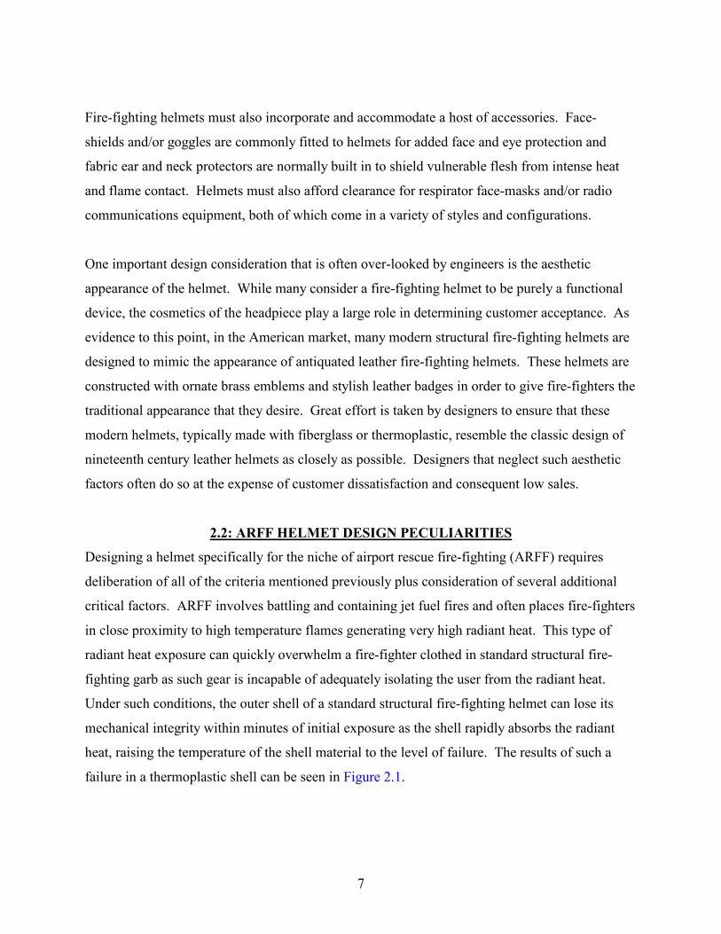
2.2: ARFF HELMET DESIGN PECULIARITIES
Designing a helmet specifically for the niche of airport rescue fire-fighting (ARFF) requires
deliberation of all of the criteria mentioned previously plus consideration of several additional
critical factors. ARFF involves battling and containing jet fuel fires and often places fire-fighters
in close proximity to high temperature flames generating very high radiant heat. This type of
radiant heat exposure can quickly overwhelm a fire-fighter clothed in standard structural fire-
fighting garb as such gear is incapable of adequately isolating the user from the radiant heat.
Under such conditions, the outer shell of a standard structural fire-fighting helmet can lose its
mechanical integrity within minutes of initial exposure as the shell rapidly absorbs the radiant
heat, raising the temperature of the shell material to the level of failure. The results of such a
failure in a thermoplastic shell can be seen in Figure 2.1.
7

Since the radiant heat from such fires can quickly degrade protective apparel, fire-fighting gear
for ARFF applications must be designed to minimize the amount of radiant heat taken in by the
paraphernalia. This is accomplished by seeking materials with the lowest possible
absorptivity/highest possible reflectivity on all outside exposed surfaces. Current state-of-the-art
ARFF helmet technology uses covers, or shrouds over standard structural fire-fighting helmets.
These shrouds are typically made from aramid-fiber textiles with an aluminum foil bonded to the
fabric. Such a shroud can be seen in Figure 1.2. This technology was developed in the 1950’s
and has been in use in ARFF helmets mostly unchanged since that time.
While many metals could be bonded to the textile substrates in ARFF shrouds, aluminum has
conventionally been the metal of choice for several reasons. First, the physical properties of
aluminum allow it to be easy formed into thin films and bonded to textiles with adhesives. It
also has a comparatively low density which minimizes the weight of the finished product. More
importantly, however, is the spectral reflectivity of material. Aluminum, in a polished,
unoxidized form, exhibits a reflectivity higher than most other metals and its high reflectivity
remains consistent over a broad range of spectral wavelengths. These characteristics, when
combined with its relatively low price, make aluminum an optimum choice for using in ARFF
applications.
2.3: SHORTCOMINGS OF CURRENT ARFF SHROUDS
While aluminized textile shrouds are quite effective in reflecting away radiant heat, there are
several noteworthy drawbacks to these products. One such shortcoming is the non-permanent
nature of the shrouds. Since the shrouds are merely covers that fit over the helmet shells, they
must be assembled onto the helmets for use and disassembled for maintenance, cleaning, and
decontamination. As the shrouds generally fit quite snuggly, such assembly can be an obstinate
and time-consuming task. Because the shrouds are made from woven textiles, the exposed
surfaces of the shrouds are rough with many small crevices. These crevices are prone to trapping
soot, dirt, and other debris. As debris accumulates, the reflectivity of the surface declines and the
effectiveness of the shroud in reflecting radiant heat is adversely effected. These contaminants
can be removed from the material by brushing and/or laundering but repeated cleaning can
8

abrade and wear the aluminum coating from the textile substrate, permanently degrading the
product and its performance. Additionally, because the shrouds are not securely linked to the
helmet shells, they can be snagged or caught on objects while in use, threatening the security of
the shroud attachment and consequently, the protection of the user. Abrasions to the shrouds can
also scrap away the aluminum coating from the substrate, thereby greatly reducing the
reflectivity of the surface and degrading performance and user safety. Finally, current
technology shrouds are quite expensive, adding as much as fifty percent to the cost of a helmet.
2.4: PERFORMANCE CRITERIA
Some design factors can be evaluated quantitatively with analytical tools, computer simulations,
or experimental research while other aspects require qualitative analysis by means of customer
surveys and competitive benchmarks. Many of the quantitative criteria are governed by industry
regulations. In the United State, the National Fire Protection Association (NFPA) establishes
regulations and guidelines for the design and performance of fire-fighting apparel, including
helmets. While compliance to NFPA criterion is not required by law in most locations, the
majority of fire departments mandate their helmets to be certified to NFPA standards. Therefore,
the performance benchmarks cited by NFPA standards become edicts by which designers must
abide. The standard related to ARFF helmets is NFPA 1976-20001. This standard institutes
minimum levels of performance related to impact force attenuation, physical penetration
resistance, physical deformation, flame retardance, electrical insulation, retention of components,
corrosion of metal components, label durability and legibility and radiant heat transmittance.
To some level NFPA 1976-2000 does an admirable job of defining important aspects of ARFF
helmet design and establishing reasonable levels of performance. In some areas, however, the
NFPA standard falls short of achieving the level of specificity and sophistication needed to
ensure a realistic and consistent degree of product performance, specifically in the area of shell
absorptivity/emissivity. Section 6-1.6.7 states, “The radiant panel shall be adjusted to obtain a
stable uniform irradiance of 1.0 W/cm2 � 0.1 W/cm2 …”. While this requirement rightly
prescribes and limits the amount of radiant heat allowed to transmit to the helmet shell, its scope
1 National Fire Protection Association, “NFPA 1976-2000: Protective Ensemble for Proximity Fire Fighting”, National Fire Protection Association, Quincy, Massachusetts, 2000.
9

is poorly defined and is inadequate to properly address the true intent of the standard, namely
ensuring adequate protection to ARFF fire-fighters under the conditions most likely to be
encountered. Specifically, the standard fails to address the spectral variation of
absorptivity/emissivity exhibited by surfaces. While the magnitude of the radiant heat flux is
defined for the test, the nature of the radiant heat source is not addressed. The radiant heat
source temperature and the distance of the source to the specimen are arbitrary and left to the
discretion of the one performing the test so long as the specified heat flux level is achieved.
With the spectral nature of absorptivity/emissivity properties, it is conceivable that a particular
test case could produce conforming results to the standard at a given source temperature, yet
miss the mark considerably when exposed to the same experiment conducted with a different
source temperature, and distance.
An important aspect of ARFF helmet design not addressed by NFPA is the abrasion resistance of
the shell and/or shell covering or coating. For fire-fighting helmets that are not exposed to high
radiant heat, scratches, nicks, and other surface imperfections are mainly a cosmetic issue. For
ARFF helmets, however, such blemishes can significantly jeopardize the performance of the
product. Since reflectivity is a surface property and these helmets rely on a high reflectivity to
reflect away radiant heat, any damage to the helmet’s surface potentially degrades (lowers) the
reflectivity of the shell and hence its ability to provide the necessary level of protection to its
user. Given the nature of fire-fighting activities, bumps, abrasions, and minor impacts are
largely unavoidable to fire-fighting helmets in service. With the performance level directly
related to the condition of the helmet surface and the inescapable battering that helmets endure,
the surface of the helmets must be highly resistant to damage.
2.5: TECHNOLOGY ADVANCEMENT
Given the formidable list of requirements and constraints on fire-fighting helmets and ARFF
helmets in particular, the design of these helmets is no simple task. Any new technology brought
to this application must advance the level of performance in one or more areas of concern
without sacrificing the ability of the product to meet all other expectations. The greatest
potential for advancing the state-of-the-art in ARFF helmet design is the development of new
shell technology that reduces or eliminates the many shortcomings of current aluminized textile
10

shrouds. In order to achieve such an advance, two primary criterion must govern the search for a
new surface technology. The two overriding properties of the surface are a high reflectivity over
a spectrum of radiant wavelengths and a high resistance to surface damage, or toughness. A
surface achieving acceptable results in the area of either reflectivity or toughness without
realizing satisfactory performance in the other area is of no practical value for use in ARFF
helmets as both characteristics must meet minimum levels of performance to be suitable for the
application.
Certain levels of helmet performance have established benchmarks as set by the NFPA. As
mentioned previously, NFPA 1976-2000 prescribes the maximum temperature rise for a helmet
shell under a specified heat flux magnitude but fails to consider spectral variation in surface
reflectivity. To guarantee fire-fighter protection in a more meaningful way, experimental
procedure and methods must be enhanced and expanded to measure shell temperatures over
varying wavelengths in the range likely to be encountered by fire-fighters performing their
duties. As no industry standards exist for evaluating helmet surface toughness, methods of
evaluation and experimentation must be invented, and evaluated. The development of protocol
for appraising reflectivity and toughness properties is discussed in Chapter III.
11

Figure 2.1: Thermoplastic Helmet After Exposure to High Radiant Heat
12

CHAPTER III: METHODOLOGY/EXPERIMENTATION
3.1: EXPERIMENTAL OBJECTIVES
With insufficient or non-existent industry standards and test methods available for evaluating the
effectiveness of helmet surfaces, new techniques for evaluating product performance had to be
developed. The methodology chosen provided reliable and accurate appraisal of specimen
performance under controlled laboratory conditions. The methodology defined repeatable
processes by which specimens were evaluated in regards to the two critical aspects of the study,
namely durability, as applied to abrasion resistance, and spectral reflectivity/absorptivity. The
study focused on performance relative to a radiant source at temperatures of 700 K to 1000 K.
To properly assess the relative performance of multiple specimens, test methods minimized
variations in and/or accounted for environmental factors, equipment variability, instrument
accuracy, and human subjectivity. Experiments were designed to assess the performance of the
helmet shells in regards to durability and spectral absorptivity/emissivity.
3.2: TEST APPARATUS
To assess the ability of the shells to reflect radiant heat at various spectral wavelengths, test
protocol and equipment were developed. The absorptivity/emissivity test set-up can be seen
schematically in Figure 3.1 and photographically in Figure 3.2 and Figure 3.3. The test system
consisted of an electrically powered black-body radiant heat source on a frame with its radiating
surface facing downward. A rolling fixture held helmet shells in the proper orientation,
transported the specimens under the heat source, and then moved them away from the source
subsequent to radiant exposure. Thermocouples attached to the inside surfaces of the shells
tracked the temperature of the surfaces.
3.3: RADIANT HEAT SOURCE
Designing this experimental arrangement involved sourcing hardware and inventing and
fabricating some necessary components. The first challenge was securing a reliable source of
radiant heat that could safely be used in a controlled laboratory environment. The source had to
simulate radiant heat from high intensity fire yet pose no threat to surrounding equipment or
furnishings. The heat source also needed to have a near-black surface (emissivity near 1.0 over a
13

wide spectral range) and maintain its surface temperature with little variation so that its
production of radiant heat was as constant as possible, both in magnitude and in its spectral
nature. A 30 cm by 45 cm, 5 kW radiant heater was used for the heat source (see Figure 3.4).
Such heaters were not commercially available as the power requirement and energy density were
beyond the guidelines for safe industrial use. However, due to the special care and attention
given to the operation of the device during this study, a prominent heater manufacturer loaned an
experimental heater for research purposes. This heater consumed over 10 amperes of electrical
current, operating at 480 Volts, three-phase alternating current. The surface of the heater
reached a maximum temperature over 1000 K, radiating freely into an open laboratory
environment. Varying the temperature of the heater surface and keeping it within set limits
required a closed-loop control system. A high temperature type K thermocouple (wire diameter
of 0.5 mm) was placed in contact with the heater surface and connected to an electronic
thermostat. The thermostat was in turn connected to a 480 VAC contactor that opened and
closed the power supply circuit of the heater.
3.4: ROLLING TEST FIXTURE
With the radiant heat source hardware and control system in place, a safe and repeatable
technique for holding helmet shell test units needed development. The test arrangement
demanded that test specimens be quickly moved into the radiant heat flux produced by the
heater, held securely for the specified duration, and then quickly removed from the radiant heat
flux. Throughout this process, the temperature of the inner surface of the shells was recorded,
along with the ambient air temperature. Maintaining a constant heat flux magnitude at the shell
surface while subjecting the specimens to radiant heat of different spectral characteristics
(produced by different heater temperatures) required the distance from the shells to the radiant
heater surface to be adjustable. In addition, since many shells were subjected to the
experimentation, a set-up affording easy specimen changes offered benefits. To accomplish all
of this, custom apparatus had to be designed and fabricated. The device created for this purpose
can be seen in Figure 3.5 with a detailed photograph of the mounting block shown in Figure 3.6.
Looking much like a modified utility cart, the rolling test fixture enabled achievement of the
aforementioned goals by combining simple design elements into a useful package. Riding on
14

casters, the U-shaped frame of the fixture enabled the apparatus to roll under the radiant heater
without interference. The rolling fixture fit into the U-shaped frame, which held the heater such
that proper alignment resulted when the fixture was fully pushed into the frame (see Figure 3.3).
This, in turn, assured that the helmet shell specimens, specifically the points of interest nearest
the thermocouples, were held directly under the center of the heater for each experiment. Helmet
shells attached to the fixture via pins that slid out from a mounting block above the ambient
thermocouple and engaged the chinstrap mounting holes in the shells. With this mounting
arrangement, helmet shells securely attached to the test fixture and exchanging shell specimens
took only a few seconds, maximizing the value-added time of experimentation. The mounting
block attached to a vertical pole clamped to a brace in the upper frame of the fixture. By
loosening the clamp, the pole could be raised or lowered to adjust the height of the shell
specimen. Marks on the pole afforded easy measurement of the distance between the shell and
the heater surface. Below the pole, a flat platform offered a resting place for the electronic
measuring equipment required for the experiments, namely a digital thermocouple reader and a
digital transducer for the radiometer used in calibration. The platform allowed the electronic
equipment to move with the test fixture and shell specimens which avoided cumbersome
connections to stationary instruments. The platform also served as a radiant heat shield
protecting the delicate equipment from damage. The platform also simplified adjustment of the
shell specimen position as a bubble level was set on the platform during adjustment to ensure
that the platform (and thus the parallel mounting block and ultimately the shell specimen) was
level and parallel to the heater surface prior to experimentation. With all of these elements, the
custom designed fixture allowed the helmet shell specimens to quickly and accurately be located
in the proper position relative to the heater, accounting for all three spatial dimensions plus
rotation. It also allowed experiments to be conducted with proper instrumentation integral to the
system, rapid exchange of test specimens, and convenient and accurate adjustment of
experimental parameters.
3.5: TEMPERATURE MEASUREMENT
The radiant heater and the custom-built test fixture provided the means necessary to evaluate the
performance of a number of different helmet shells under high radiant heat conditions. The
established test methods benchmarked the intent of NFPA 1976-2000. Specifically, the specified
15
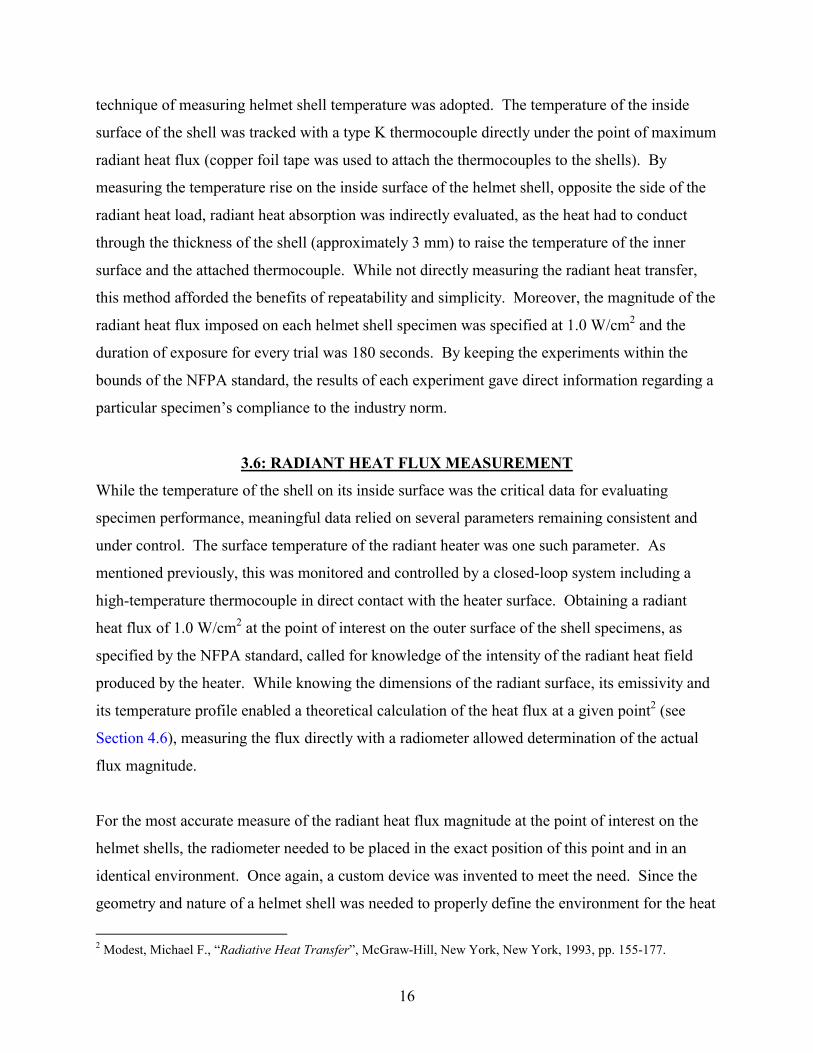
technique of measuring helmet shell temperature was adopted. The temperature of the inside
surface of the shell was tracked with a type K thermocouple directly under the point of maximum
radiant heat flux (copper foil tape was used to attach the thermocouples to the shells). By
measuring the temperature rise on the inside surface of the helmet shell, opposite the side of the
radiant heat load, radiant heat absorption was indirectly evaluated, as the heat had to conduct
through the thickness of the shell (approximately 3 mm) to raise the temperature of the inner
surface and the attached thermocouple. While not directly measuring the radiant heat transfer,
this method afforded the benefits of repeatability and simplicity. Moreover, the magnitude of the
radiant heat flux imposed on each helmet shell specimen was specified at 1.0 W/cm2 and the
duration of exposure for every trial was 180 seconds. By keeping the experiments within the
bounds of the NFPA standard, the results of each experiment gave direct information regarding a
particular specimen’s compliance to the industry norm.
3.6: RADIANT HEAT FLUX MEASUREMENT
While the temperature of the shell on its inside surface was the critical data for evaluating
specimen performance, meaningful data relied on several parameters remaining consistent and
under control. The surface temperature of the radiant heater was one such parameter. As
mentioned previously, this was monitored and controlled by a closed-loop system including a
high-temperature thermocouple in direct contact with the heater surface. Obtaining a radiant
heat flux of 1.0 W/cm2 at the point of interest on the outer surface of the shell specimens, as
specified by the NFPA standard, called for knowledge of the intensity of the radiant heat field
produced by the heater. While knowing the dimensions of the radiant surface, its emissivity and
its temperature profile enabled a theoretical calculation of the heat flux at a given point2 (see
Section 4.6), measuring the flux directly with a radiometer allowed determination of the actual
flux magnitude.
For the most accurate measure of the radiant heat flux magnitude at the point of interest on the
helmet shells, the radiometer needed to be placed in the exact position of this point and in an
identical environment. Once again, a custom device was invented to meet the need. Since the
geometry and nature of a helmet shell was needed to properly define the environment for the heat
2 Modest, Michael F., “Radiative Heat Transfer”, McGraw-Hill, New York, New York, 1993, pp. 155-177.
16

flux measurement, an actual helmet shell was used to create a holder for the radiometer. By
boring a hole in a helmet shell and mounting the radiometer through the hole, flush with the
outer surface of the shell, the radiometer occupied the very space of the point of interest of the
test specimens. As can be seen from the photograph of Figure 3.7, the shell used for mounting
the radiometer was vacuum metalized with aluminum to provide a highly reflective outer surface
minimize the radiant heat absorbed by the shell. This was necessary to protect the shell from
degradation and to shield the radiometer housing and wiring from the radiant heat emitted by the
heater. This assembly became a calibration fixture for the experiments. Made from a helmet
shell, the calibration fixture mounted to the holding fixture exactly as the test specimens. The
leads from the radiometer connected to the transducer, which rested on the platform of the fixture
and displayed a continuous, instantaneous value for the radiant heat flux at the radiometer
surface. Prior to each set of experiments, once the temperature of the heater was stabilized at its
specified value, the calibration fixture, mounted to the test fixture, rolled into position under the
heater. The clamp on the pole of the test fixture was loosened and the pole was moved vertically
until a toleranced reading of 1.0 W/cm2 displayed on the radiometer transducer. With the
position checked for level and adjusted as necessary, the clamp was tightened to fix the position
of the pole. After this, the test fixture rolled away from the heater, and the calibration fixture
was replaced with a test specimen with the thermocouple reader taking the place of the
radiometer transducer on the platform. Thus, when the test specimen rolled into position under
the heater for testing, the point of interest on the helmet shell coincided exactly with the location
of the radiometer during the height adjustment calibration, thereby ensuring that the point of
interest on the test specimen saw a radiant heat flux of the specified magnitude.
3.7: DATA ACQUISITION
The last parameter requiring attention was the sampling time at which thermocouple readings
were recorded. The data logging function of the digital thermocouple reader greatly simplified
this task. When the test fixture, holding a test specimen, rolled into position under the heater, the
data logging function was manually started and the temperature of the thermocouple was
automatically recorded for “time zero” and every ten seconds thereafter for three minutes for a
total of 19 data points per test. The digital thermocouple reader also collected readings from the
17

ambient air temperature thermocouple at the same rate. This feature assured accuracy in data
collection and precision in sampling intervals.
3.8: RATIONALE FOR METHODOLOGY
While NFPA standards guided the research, the scope of the experimentation exceeded industry
guidelines. Initial tests for each shell specimen were conducted with a heater surface
temperature of 700K. After each series of experiments, the heater surface temperature was
increased in increments of 100K up to the highest tested temperature of 1000 K for a total of four
radiant exposure experiments for each helmet shell specimen. For each temperature setting, the
calibration fixture enabled height adjustment of the helmet shells such that the point of interest
incurred a radiant heat flux of the specified 1.0 W/cm2 magnitude. With the magnitude of the
heat flux constant throughout each series of experiments but with varying heater temperatures,
the effect of the heater temperature on helmet shell temperature rise emerged. As the peak
wavelength of radiant heat varies inversely with source temperature for a given radiant heat flux
according to Wien’s law3, a correlation of radiation wavelength versus helmet shell temperature
rise emerged. With radiation being the dominant mode of heat transfer for these experiments,
the measured temperature rise of the shell linked directly to the radiant heat absorbed by each
helmet shell specimen during each trial. Knowing that the radiant heat absorbed by a body
depends proportionally on the body’s absorptivity4, the observed temperature rise correlated
directly to the absorptivity of each specimen. Combining this information and data led to a
correlation of the relative absorptivity of each helmet shell specimen to the wavelength of
incident radiant heat. While not producing exact quantitative absorptivity values, relative
spectral absorptivities emerged for the various helmet shell constructions tested.
3.9: ABRASIVE CONDITIONING
The second critical characteristic examined in this research was the toughness of the helmet
shells, or their ability to resist damage,. Specifically, the resistance to degradation from abrasion
3 Modest, Michael F., “Radiative Heat Transfer”, McGraw-Hill, New York, New York, 1993, pp. 5-13. 4 Incropera, F.P., Dewitt, D.P., “Fundamentals of Heat and Mass Transfer,” Second Edition, John Wiley & Sons, New York, 1985, pp. 664-665.
18

underwent evaluation. As no industry standard existed for the evaluation of such criteria, test
methods evolved from knowledge of common treatment of fire-fighting helmets and hazards
involved in the use of such equipment. Inspection of helmets worn by fire-fighters in service
attested to the frequent abrasions and light impacts inflicted to fire-fighting helmets. While such
treatment of helmets in actual fire-fighting use is unpredictable and dependent upon many
environmental and human factors, the test protocol established a repeatable and consistent
evaluation trial for judging the resistance of specimens to such hazards.
Inspired by test protocol for assessing the scratch resistance of optical components5, the
experiment specified that the point of interest on the helmet shells endure abrasions from an
object of known surface roughness, under a known downward force, for a specified number of
iterations. As in the radiant heat exposure experiments, custom designed and built equipment
provided the means of assessing specimen performance. The apparatus used for abrading the
helmet shells can be seen in Figure 3.8. The device consisted of a mounting block, similar to the
one used on the test fixture for the radiant exposure experiments, to secure the helmet shells to a
sliding rail assembly. The sliding rail articulated fore and aft, propelled by a pneumatic cylinder.
A beam above the sliding rail supported a second smaller pneumatic cylinder with its shaft
extending downward toward the rail. A wooden block mounted to the small cylinder shaft and
commercial sandpaper attached to the block with staples. An air pressure gage was fitted to the
small cylinder to monitor the force on the cylinder shaft and consequently on the sandpaper and
block. This arrangement is detailed in Figure 3.9.
Pneumatic controls plumbed the device such that, upon depression of the start button, the top
cylinder was pressurized, forcing the sandpaper block downward with a known constant force.
The cylinder connected to the sliding rail moved the helmet specimen forward, forcing it under
the sandpaper block, positioned to ride across the point of interest on the helmet shell. The
cylinder then reversed direction, pulling the shell backward with the sandpaper block still
5 National Fire Protection Association, “NFPA 1971-2000: Protective Ensemble for Structural Fire Fighting”, National Fire Protection Association, Quincy, Massachusetts, 2000.
19

abrading the shell. The back and forth movement of the shell continued for the number of
iterations set on the pneumatic control counter.
The most important aspect of evaluating the helmet shells resistance to abrasion involved the
establishment of consistent parameters to enable the various specimens to be compared on an
even scale. Without applicable standards or defined environmental levels of severity, test
parameters were chosen to reasonably simulate abrasions encountered in real use situations based
on familiarity of the treatment of fire-fighting helmets. For this research, sandpaper with a
commercial 100-grit finish abraded the shell specimens under an applied force of 60 Newtons.
Each shell passed forward and backward under the abrading block a total of five times. While
the parameters were somewhat arbitrary, they provided consistent conditioning of the helmet
shells enabling fair comparisons to be made.
3.10: ABRASION EFFECTS
The abrasive test served not only to expose the fragility of the helmet shells’ surface and
appearance but provided a means of conditioning for a second round of radiant heat experiments.
Subsequent to the abrasive testing/conditioning, each helmet shell specimen was inspected and
the effects of the abrasion were noted. (Photographs of the abraded areas of several specimens
can be seen in Figures C.1 through C.9 in Appendix C.) Then, all samples underwent the radiant
heat exposure experiment a second time. All experimental methods and parameters remained
unchanged from the first series of radiant experiments. Upon completion of the second series of
radiant tests, each helmet shell specimen possessed two complete series of data points. Each
series referenced the shell’s temperature rise under a 1.0 W/cm2 radiant heat flux for source
temperatures ranging from 700 K to 1000 K.
With two sets of radiant heat test data for each helmet shell specimen, one for its pristine
unabraded surface and one for its abraded surface, the effects of surface abrasion on reflectivity
emerged. Comparison between each specimen’s data sets revealed the severity of performance
degradation resulting from surface damage. Additionally, relative comparisons between samples
exposed which surface technologies were most resilient to damage from abrasion. With this
20
information, the technologies best suited for the rigors of fire-fighting helmets emerged from the
field of test specimens.
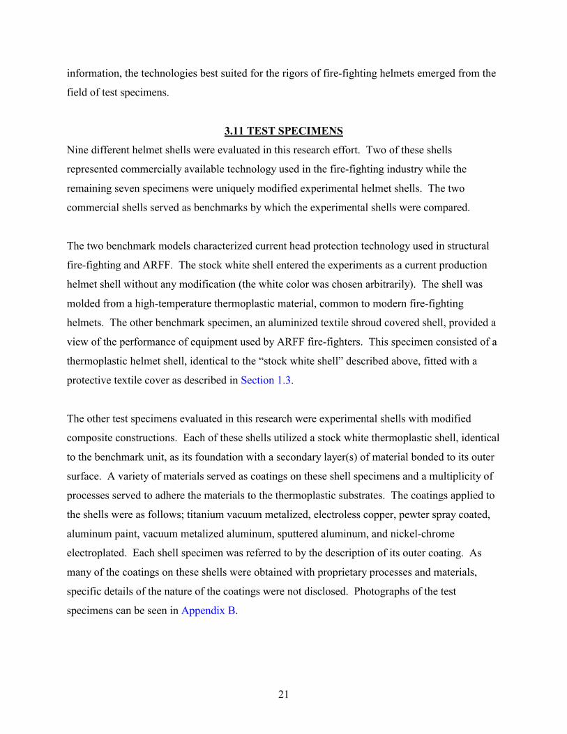
3.11 TEST SPECIMENS
Nine different helmet shells were evaluated in this research effort. Two of these shells
represented commercially available technology used in the fire-fighting industry while the
remaining seven specimens were uniquely modified experimental helmet shells. The two
commercial shells served as benchmarks by which the experimental shells were compared.
The two benchmark models characterized current head protection technology used in structural
fire-fighting and ARFF. The stock white shell entered the experiments as a current production
helmet shell without any modification (the white color was chosen arbitrarily). The shell was
molded from a high-temperature thermoplastic material, common to modern fire-fighting
helmets. The other benchmark specimen, an aluminized textile shroud covered shell, provided a
view of the performance of equipment used by ARFF fire-fighters. This specimen consisted of a
thermoplastic helmet shell, identical to the “stock white shell” described above, fitted with a
protective textile cover as described in Section 1.3.
The other test specimens evaluated in this research were experimental shells with modified
composite constructions. Each of these shells utilized a stock white thermoplastic shell, identical
to the benchmark unit, as its foundation with a secondary layer(s) of material bonded to its outer
surface. A variety of materials served as coatings on these shell specimens and a multiplicity of
processes served to adhere the materials to the thermoplastic substrates. The coatings applied to
the shells were as follows; titanium vacuum metalized, electroless copper, pewter spray coated,
aluminum paint, vacuum metalized aluminum, sputtered aluminum, and nickel-chrome
electroplated. Each shell specimen was referred to by the description of its outer coating. As
many of the coatings on these shells were obtained with proprietary processes and materials,
specific details of the nature of the coatings were not disclosed. Photographs of the test
specimens can be seen in Appendix B.
21

Figure 3.1: Schematic of Radiant Heat Exposure Test
22

Figure 3.2: Experimental Test Apparatus Disengaged
23
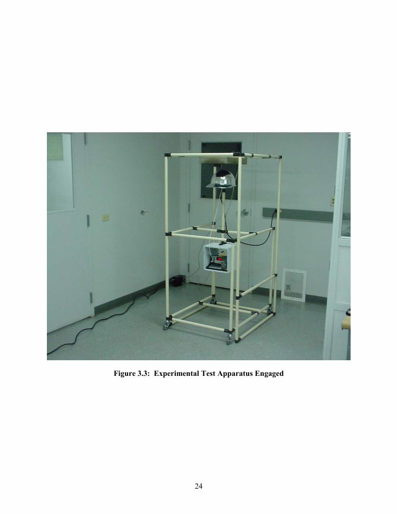
Figure 3.3: Experimental Test Apparatus Engaged
24

Figure 3.4: Radiant Heater
25

Figure 3.5: Rolling Test Fixture
26

Figure 3.6: Helmet Shell Mounting Block
27

Figure 3.7: Radiometer Installed into Metalized Helmet Shell
28

Figure 3.8: Abrasion Apparatus (click for animation)
29
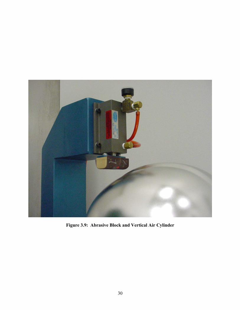
Figure 3.9: Abrasive Block and Vertical Air Cylinder
30

CHAPTER IV: THEORETICAL CONSIDERATIONS & MODELING
4.1: LITERATURE SEARCH
While a significant volume of work has focused on the nature of radiant heat transfer, a minimal
amount of published study has explored the field in the demanding application of fire-fighter
protection. Manufacturers of personal protective equipment have disclosed little about any
research into this area that may have been conducted by private firms. The National Fire
Protection Association (NFPA) has published a limited volume of information regarding Airport
Rescue Fire-Fighting (ARFF) but the majority of the information contained within such
publications are related to industry standards as discussed in Section 1.2. Standard operating
procedures for the use and care of personal protective equipment are readily available but
information detailing the performance of such paraphernalia in service or meaningful
engineering data is quite limited. What little published technical work that is available on the
subject fire-fighting protective gear is primarily focused on textile fabrics used in the
construction of garments. In the absence of published material regarding fire-fighting head
protection or similar specific research to build upon, general principles discovered and developed
by combustion and fire science and radiation heat transfer were applied to the realm of fire-
fighting helmet evaluation.
4.2: FIRE SCIENCE SUMMARY
In the last several decades, greater effort has been spent on researching and understanding
combustion and fire science. A large amount of these studies have been dedicated to the area of
combustion engines and power generation, while other efforts have focused on open fires and
flame characteristics. Some of the later type of research has centered on the area of fire-fighting,
primarily targeting fire prevention and enhancing understanding of phenomena involved in flame
spread and propagation. Significant strides have been made in defining and analyzing the factors
involved in open fires. As mentioned previously, however, only a few studies have dealt with
fire-fighter safety and protection, although some of the findings provide useful insight to the
environmental conditions to which fire-fighters are exposed.
31

Fire researchers have determined experimentally that heat transfer from open combustion is
dominated by radiation for fires larger than 0.3 m.6 Such radiation is primarily driven by
radiating soot particles.7 While peak mean temperatures in fires are on the order of 1250 K, the
radiating soot typically models as radiating at a temperature near 1400 K.8 Radiant heat flux
produced by such fires is often modeled in magnitude as 2.0 W/cm2, corresponding roughly to
the level of heat flux at floor level from "flashover" conditions. This level of heat flux also
corresponds roughly to the level which would cause rapid pyrolysis of cellulosic materials and
produce ignition (in the presence of a pilot flame) of a flammable floor covering.9
Such quantitative reference data is valuable in appraising the appropriateness of the parameters
established for the experimentation of the present research. In terms of heat flux magnitude and
source temperature, the experimental limits were notably lower than levels known to exist in real
fire environments. As detailed in Chapter III, the radiant heat exposure tests subjected the
helmet shell specimens to a radiant heat flux of 1.0 W/cm2 from a source at temperatures ranging
from 700 K to 1000 K. The effects of radiant source temperature are discussed in Section 5.3
and the correctness of the experimental parameters and opportunities for better reproducing
actual fire conditions are discussed in Section 6.5.
6 Cox, Geoffrey, "Combustion Fundamentals of Fire," Academic Press, San Diego, CA, 1995, p. 4. 7 Ibid, p. 276. 8 Ibid, pp. 260-262. 9 Ibid, p. 315
32

4.3: SURFACE PROPERTIES
As this research dealt only with opaque materials, the radiation heat transfer was analyzed as a
surface phenomenon.10 In other words, the reflection and absorption of radiant heat were
assumed to occur within a fraction of a micrometer from the irradiated surfaces with reflected
radiation having no net effect on the medium, while absorbed radiation increased the thermal
energy of the medium resulting in a measured temperature rise.11 As the sum of the surface
absorptivity and reflectivity for opaque surfaces is unity12, knowledge of either property provides
knowledge of the other. For this reason, the terms are used alternately throughout this text.
Knowledge from the area of optics and optical coatings was useful in evaluating and analyzing
the coatings applied to the helmet shell specimens. As in the case of optical components, the
reflectivity of a metallic surface or coating strongly depends on the characteristics of the
chemical and mechanical treatment of the surface.13 The properties of vacuum deposited
metallic surfaces are markedly different from the surfaces of bulk metals prepared by finishing or
polishing.
Previous researchers studying vacuum deposited (metalized) surfaces discovered that such
surfaces exhibit higher reflectivities than polished surfaces of the same material14. The
reflectivity for aluminum evaporated films, for example, are very near unity for spectral
wavelengths over 2 µm.15 Knowledge of such material properties suggested that a vacuum
deposited aluminum film bonded to the outer surface of a fire-fighting helmet shell may provide
the desired level performance in regards to radiant heat transfer. Such a specimen was obtained
and included in the assortment of shells tested in this research effort. The test data for this
specimen may be seen in Table A.6. The high reflectivity values for aluminum films also
explains the choice of material used in current state-of-the-art ARFF shrouds as discussed in
10 Incropera, F.P., Dewitt, D.P., “Fundamentals of Heat and Mass Transfer,” Second Edition, John Wiley & Sons, New York, 1985, p. 635. 11 Ibid, p. 663. 12 Ibid, p. 667. 13 American Institute of Physics, “American Institute of Physics Handbook”, McGraw-Hill, New York, New York, 1972, p. 6-119. 14 Ibid, p. 6-157. 15 Incropera, F.P., Dewitt, D.P., “Fundamentals of Heat and Mass Transfer,” Second Edition, John Wiley & Sons, New York, 1985, p.667.
33

Section 1.3. One such shroud covered shell was also included in the host of test specimens. The
significance of their performances relative to industry standards, meaningful targets, and other
test specimens is discussed in Chapter V and Chapter VI.
4.4: ANALYTICAL MODELING
The heat transfer phenomena affecting the measured temperature rise as recorded on the inside of
the helmet shell included radiation, convection, and conduction with radiation being the
dominant mode.
To better understand the heat transfer phenomena involved in the experiments and to validate the
experimental observations, two different heat transfer models were developed. Both models
were one-dimensional. The first model was developed based on a constant heat flux incident
upon the outer shell surface. The second model was generated to more accurately represent
actual experimental radiant heat transfer conditions. The variables and nomenclature used in the
models and equations are defined page x.
Since the geometry of the helmet shells was composed of complex, three-dimensional curved
surfaces, the shells could not be satisfactorily modeled in their entirety with any reasonable
analytical equations. With only the points of maximum radiant heat flux of interest, however,
infinitesimal differential elements at the points nearest the radiant panel could be evaluated and
one-dimensional models achieved the desired heat transfer representation. Therefore, the
analytical models were designed to consider only differential elements on the top surface of the
helmet shells for the heat transfer equations.
34

4.5: CONSTANT HEAT FLUX MODEL:
As each experiment was calibrated to initialize with a radiant heat flux of 1.0 W/cm2 incident on
the helmet shell outer surface, the first analytical model prescribed a constant heat-flux of 1.0
W/cm2 at the outer shell surface. The thermal properties of the shell material were assumed to be
homogeneous and constant. The effects of convective heat transfer were not considered and the
inner shell surface was considered to be adiabatic. A schematic of the model can be seen in
Figure 4.1.
Qh" = 1.0 W/cm2
x = 0
x = d Figure 4.1: Heat Flux Model Schematic The transient heat conduction equation was developed as follows: Taking a differential slice along a constant “x” value, the heat entering the slice is:
t)dt(x,xTkdQin�
�� [1]
The heat leaving the slice is:
t)dtdx,(xxTkdQout ��
�� [2]
The thermal energy difference through the differential slice is then:
2
2
inout xTdxdtkdQdQdQ
�
������� [3]
The rate of heat absorption by the differential slice is given by:
tTdtdxcρdQ p�
������ [4]
35

Equating [3] and [4]:
2
2
p xT
cρk
tT
�
�
��
�
� [5]
Defining the thermal diffusivity, �:
pcρkκ�
� [6]
then
[7]2
2
xTκ
tT
�
��
�
�
The boundary and initial conditions were specified as follows: Constant heat flux on outer surface;
"hQ
xTk ��
� , at x = 0 [8]
Initially isothermal;
[9]T = Ti, at t = 0
0xT�
�
� , at t = 0 [10]
Adiabatic at inner surface;
0xT�
�
� , at x = d [11]
36

4.6: RADIANT HEAT TRANSFER MODEL:
To better mimic the conditions of the physical experiments, the second analytical model
considered the radiation transfer and the detailed arrangement of the test layout. Geometry was
established such that the differential element was directly centered beneath a black-body radiant
panel at a variable distance just as in the experimental arrangement. No provision for re-
radiation from the shell to the environment was provided. The thermal properties of the shell
materials were assumed to be homogeneous and constant. The effects of convective heat transfer
were not considered and the inner shell surface was considered to be adiabatic. A schematic of
the model can be seen in Figure 4.2.
440 mm
285 mm Radiant Panel
Helmet Shell Element x = d
Figure 4.2: Radiant Model Schematic
H
x = 0
The first step in calculating the radiant heat transfer to the shell element was determining the
view factor between the differential element and the radiant panel. This effort was simplified by
using a view factor reference catalog containing the desired view factor relationship and the
additive property of view factors16. For a differential planar element to a finite parallel rectangle
with the normal to the element passing through a corner of the rectangle, the view factor relation
is given in Figure 4.317:
37
16 Modest, Michael F., “Radiative Heat Transfer”, McGraw-Hill, New York, New York, 1993, pp.173-177. 17 Ibid, p. 783.

a
b
cA = a/c B = b/c
���
�
���
����
�
�
�
��
�
�
� ��
2
1
22
1
2 B1Atan
B1B
A1Btan
A1A
2π1F [12]
Figure 4.3: View Factor Catalog Solution
For the helmet shell element model, the rectangular radiant panel was centered about the normal
to the element. In order to use the catalog solution, the panel was evaluated as four quadrants
and the summation property was used to obtain the total view factor. Thus, entering the
applicable values for the variables, the view factor was calculated:
H220mmA � [13]
H142.5mmB � [14]
���
�
���
����
�
�
�
��
�
�
� ��
2
1
22
1
2TB1
AtanB1
BA1
BtanA1
A2π4F [15]
Neglecting re-radiation to the environment and assuming the emissivity of the radiant panel to be
unity, the total radiant heat flux incident upon the differential shell element was taken to be:
Q" = FT�(�sTh
4 – �sTs4) [16]
38

As in the constant heat-flux model, the differential equation for transient heat conduction
(Equation 7) can be used to model the conduction through the helmet shell thickness.
2
2
xTκ
tT
�
��
�
� [17]
In this case, however, the boundary conditions were as follows:
Radiant heat flux on outer surface;
)TεTσ(αFxTk 4
ss4hsT ��
�
� , at x = 0 [18] Initially isothermal;
T = Ti, at t = 0 [19]
0xT�
�
� , at t = 0 [20]
Adiabatic at inner surface;
0xT�
�
� , at x = d [21]
39

4.7: SPECTRAL EMISSIVITY & ABSORPTIVITY
The emissivity of the helmet shell, εs, and absorptivity of the helmet shell, αs, introduced in
Equation 16, are important properties of the shell surface and are spectral in nature (i.e. their
values are dependent upon radiant wavelength). Understanding this variation of emissivity and
absorptivity with wavelength was an important aspect of this study. As the direction of radiant
emission was constant in these experiments, the directional natures of these properties were not
considered. The spectral hemispherical emissivity of the helmet surface, ελ,s, is defined as:
)T,(E)T,(E
)T,(εsbλ,
ssλ,ssλ,
�
�� � [22]
Integrating over all possible wavelengths, yields the total hemispherical emissivity of the shell:
)(TE
)dλT,()ET,(ε)(Tε
sb
0 sbλ,ssλ,ss
��
�
��
[23]
Similarly, the spectral hemispherical absorptivity of the helmet surface, αλ,s, may be found by:
� �� �
� ����
λ
absλ,sλ, G
λGα
[24]
Integrating over all possible wavelengths, gives the total hemispherical absorptivity of the shell:
� � � �
� ��
��
�
�
0 λ
0 λsλ,s
dλλG
dλλGλαα
[25]
As the radiant heat incident upon the helmet shell was produced by a blackbody radiant heater,
the irradiation may be related to the known emission of the heater to obtain:
� � � �
� �hb
0 hbλ,sλ,
s TE
dλTλ,Eλαα �
�
�
[26]
40

As discussed in Section 4.2, radiant heat from fires is dominated by soot particles emitting at an
effective temperature of approximately 1400 K. Knowing this, integrating over the entire
spectral range (λ = 0 to ∞) to find the total emissivity and absorptivity is unnecessary and less
practical than finding the effective properties over the band of wavelengths that dominate
blackbody radiation at 1400 K. For a prescribed temperature and wavelength λ, the fraction of
total blackbody emission from 0 to λ is given by:18
)Tf(λ)Td(λ Tσ
ETσ
dλE
dλE
dλEF
λT
0 5bλ,
4
λ
0 bλ,
0 bλ,
λ
0 bλ,λ)(0 �
�
�
�
�� ��
�
���
[27]
The fraction of radiant emission between any two wavelengths λ1 and λ2 is then:
)λ(0)λ(04
λ
0
λ
0 bλ,bλ,)λ(λ 12
2 1
21FF
Tσ
dλEdλEF
�����
�
�
�
� �
[28]
The spectral band in which the majority of emission is concentrated at 1400 K may then be
determined. Using the Table of Blackbody Radiation Functions from Incropera and DeWitt,19
which contains fractional functions of blackbody emissive power based on the Planck
distribution,20 and neglecting marginal wavelength intervals (below which and above which ten
percent of the radiation is concentrated), allowed calculation of the range of wavelengths that
dominate emission at this temperature. Interpolating from tabulated data, it was found that ten
percent of emission is concentrated below 2200 µm·K and ten percent of emission is
concentrated above 9382 µm·K. Dividing these values by 1400 K revealed a spectral range of
1.6 to 6.7 µm, corresponding to the range of wavelengths in which 80 percent of all emission
occurs at 1400 K. (The ten percent magnitude of the neglected marginal intervals was chosen
arbitrarily.)
18 Incropera, F.P., Dewitt, D.P., “Fundamentals of Heat and Mass Transfer,” Second Edition, John Wiley & Sons, New York, 1985, p. 649. 19 Incropera, F.P., Dewitt, D.P., “Fundamentals of Heat and Mass Transfer,” Second Edition, John Wiley & Sons, New York, 1985, pp. 650-651. 20 Ibid, pp. 647-651.
41

The effective emissivity and absorptivity of the helmet shell over this range of wavelengths may
then be quantified. This may be accomplished by replacing the limits of integration in Equations
23 and 26 with the wavelengths flanking the range of maximum emission as calculated
previously, yielding the equations:
)(TE
)dλT,()ET,(ε)(Tε
sb
7.6
1.6 sbλ,ssλ,
ss� ��
� [29]
� � � �
� �hb
6.7
1.6 hbλ,sλ,
s TE
dλTλ,Eλαα �
�
[30]
The approximation symbology in Equations 29 and 30 acknowledges that while integrating over
the finite spectral range of 1.6 to 6.7 �m encompasses the majority of the radiated emission at
1400 K, 20 percent of the emission is outside of these limits and the equation is therefore
inexact. The approximation is adequate, however, for many practical engineering applications
and accounts for the bulk of the spectral emissive distribution. Greater accuracy can be obtained
by reducing the size of the neglected marginal spectral regions and following the same
procedure.
42

4.8: COMPARISON OF RADIANT HEATER TO OPEN FIRE
While radiant heat from open fires may be approximated by 1400 K blackbody emission, the
experiments conducted in this research relied upon a radiant heater with a maximum surface
temperature of 1000 K. Using the methods previously described, the range of wavelengths
representing the center 80th percentile of radiant emission at 1000 K is found to be 2.2 to 9.4
�m. Again using the Table of Blackbody Radiation Functions from Incropera and DeWitt,21 the
accuracy of using a 1000 K heater to simulate emission from an effective 1400 K fire was
determined. Using the range of 1.6 to 6.7 �m multiplied by the temperature of 1000 K (1600 to
6700 �m·K), the fraction of radiant emission from the heater in this spectral band calculates to be
77.0 percent. This number compares nicely with the 80 percent fraction by which a 1400 K
source emits in this band, providing credibility for the use of the heater for laboratory simulation
of emission from open fires. Additionally, the peak wavelength, corresponding to the spectral
wavelength at which blackbody emission is maximum, may be compared. From Wien’s
displacement law, the maximum spectral emissive power is found by the equation: 22
TKµm 2897.8λmax�
� [31]
For the temperatures of 1000 K and 1400 K, the peak spectral wavelengths are 2.9 and 2.1 µm,
respectively. The fraction of emission from 1.6 to 6.7 �m and the peak spectral wavelength for
each experimental heater temperature and for 1400 K are tabulated in Table 4.1. The spectral
emissive power for blackbodies at these temperatures is plotted on a logarithmic scale in Figure
4.4.
21 Incropera, F.P., Dewitt, D.P., “Fundamentals of Heat and Mass Transfer,” Second Edition, John Wiley & Sons, New York, 1985, pp. 650-651. 22 Ibid, p.648.
43

Blackbody Temperature 700 K 800 K 900 K 1000 K 1400 K
Peak Spectral Wavelength 4.1 µm 3.6 µm 3.2 µm 2.9 µm 2.1 µm
Emission Fraction from 1.6 to 6.7 µm 59.1% 67.2% 73.0% 77.0% 80.0%
Table 4.1: Comparison of Spectral Characteristics
44
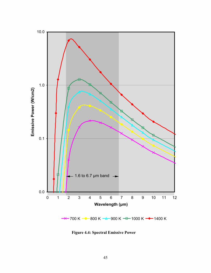
Figure 4.4: Spectral Emissive Power
0.0
0.1
1.0
10.0
0 1 2 3 4 5 6 7 8 9 10 11 12
Wavelength (µm)
Emis
sive
Pow
er (W
/cm
2)
700 K 800 K 900 K 1000 K 1400 K
1.6 to 6.7 µm band
45

CHAPTER V: EXPERIMENTAL DISCUSSION & ANALYSIS
5.1: OBSERVATIONS
Experimental data collected during this research can be seen in Appendix A. Evaluation of this
data revealed that, in most cases, the temperature of the radiant heater had little effect on the
temperature rise of the helmet shells. This indicated that within the range of spectral radiation
produced by the heater between 700 K to 1000 K, little variation manifested in the absorptivities
of the helmet shells.
The relative rankings of the helmet shell specimens with respect to their observed temperature
rises before and after abrasive conditioning were of significant interest in this study. Table 5.1
lists the shells in descending order of their temperatures rises prior to abrasion (listed with the
best performing shells last). This list identifies which specimens performed best “out of the box”
or in new, pristine condition. Table 5.2 shows the same type of ranking, but for the shells after
the abrasive conditioning described in Section 3.9. This list highlights the specimens that were
most resistant to radiant heat after enduring harsh scrapes and scratches, common to fire-fighting
helmet shells in actual field service. Examining this data in light of the NFPA standard that
requires such temperature increases to be no more than 25 �C, revealed that the only the
aluminized textile shroud covered shell complied to the standard in both abraded and unabraded
conditions. The only other specimen to achieve this level of performance was the aluminum
vacuum metalized shell in its unabraded state. This unabraded shell exhibited the best
performance (lowest temperature rise) of any specimen tested with an average measured
temperature increase of only 8.7 �C.
The outstanding performance of the unabraded aluminum vacuum metalized shell greatly
deteriorated subsequent to abrasive conditioning. The average temperature rise of this shell in
the abraded state was 86.3 �C, a 77.6 �C increase relative to its unabraded performance. This
disparity between abraded and unabraded performance for the aluminum vacuum metalized shell
was decidedly the greatest among the tested specimens. Table 5.3 shows the change in
performance of each specimen due to abrasion and ranks the shells according to their resistance
46

to performance degradation (as determined by the difference in average temperature rises) from
such abrasion.
As can be seen from Table 5.1 and Figure 5.1, all of the modified helmet shells performed
significantly better than the stock white helmet shell, exhibiting measured temperature rises 67.2
to 141.3 �C lower. This margin reduced significantly, however, after abrasive conditioning.
Table 5.2 and Figure 5.2 reveal the average performances of each specimen in its abraded
condition. While all modified helmet shells still outperformed the stock white shell, the margin
reduced to a range of 18.2 to 115.8 �C lower temperature rises. Interestingly, the five poorest
performing shells did not change in their relative rankings, while the top four specimens shuffled
positions among themselves. The stock white shell, the titanium plated shell, the electroless
plated copper shell, the pewter coated shell, and the aluminum painted shell consistently
displayed the poorest performance as exhibited by their high temperature rises. The vacuum-
metalized aluminum shell, the sputtered aluminum shell, the nickel-chrome electroplated shell,
and the textile shroud covered shell consistently shared the top four positions as exhibiting the
lowest temperature rises.
Table 5.3 ranks the specimens according to their resistance to performance degradation
subsequent to abrasive conditioning. The negative change calculated for the stock white shell
indicated that this shell actually produced lower temperature rises subsequent to abrasive
conditioning. Notably, this specimen also exhibited bubbling of its thermoplastic material, to
various degrees, after each of its experimental tests (see Figure 5.3 and Figure 5.4). The
significance of this bubble formation is discussed in Section 5.3.
47

5.2: POTENTIAL SOURCES OF ERROR
Aside from the minor inherent errors in the experimental instrumentation and measurement
devices, several factors in the experiments may have detracted from the accuracy of the results.
One significant factor was the under-damped behavior of the radiant heater closed-loop control
system. As described in Section 3.3, an electronic thermostat monitored the temperature of the
heater via a type K thermocouple placed in direct contact with the radiant heater surface. The
thermostat controlled the opening and closing of the electric circuit to the heater with the aid of a
480 VAC contactor. When the measured temperature of the heater dropped below the specified
value, the circuit was closed, providing power to the heater. Once the measured temperature
reached the specified value, the circuit was opened and power was disrupted. With the thermal
mass inherent in the radiant heater assembly, this simple control configuration allowed the
temperature of the heater surface to oscillate about the specified value by as much as 30�C in a
sinusoidal fashion. As the radiant emissive power of a surface is proportional to the fourth
power of its absolute temperature23, such variations in temperature correlated to significant
fluctuations in emitted heat flux. Such flux variation was witnessed during each calibration (see
Section 3.6) as a constant value could never be obtained on the radiometer transducer. The
distance between the heater surface and the helmet shell specimens was set to a point where the
radiant heat flux, as measured by the radiometer, varied about the specified 1.0 W/cm2 by a
symmetric magnitude (i.e. the measured heat flux oscillated between 0.93 W/cm2 and 1.07
W/cm2 such that the nominal or average value was 1.0 W/cm2). After proper adjustment, the
measured heat flux during each calibration run never strayed more than ten percent from the
specified value, which is in line with NFPA testing requirements. To minimize testing variation
induced by this fluctuation, each test initiated when the temperature of the heater, as exhibited on
the thermostat display, was at the minimum value of its sinusoidal fluctuation. This method
ensured that each test was commenced at the same point in the heater cycle.
Another factor that may have influenced the results of the experiments was heat transfer due to
convection. The experimental arrangement was such that the helmet shell specimens were tested
in an ambient laboratory environment with the radiant panel heater suspended above the
specimens with its heated surface facing downward toward the floor. With this arrangement,
23 Modest, Michael F., “Radiative Heat Transfer”, McGraw-Hill, 1993, p,13.
48

heating of the ambient air via natural convection was inevitable. Such heating would have
caused a stratification of the column of air below the heater with the hottest air naturally being
elevated near the heater surface from buoyancy effects. This heated air would have convectively
transferred heat to the surface of the helmet shell specimens when the shell surface was cooler
than the air and would have convected heat away from the shell when the shell surface was
hotter than the air. Such convective effects would have differed in magnitude from test to test in
these experiments for several reasons. First, as the distance between the radiant panel and the
helmet specimen increased as the temperature setting of the heater increased, the helmet shell
specimens were closer to the heater for the experiments conducted at lower heater temperature
settings. By occupying space nearer the heater, these low temperature trials exposed the shells to
more pronounced stratification of the surrounding air, thereby placing the point of interest on the
helmet shell in a location of higher air temperature relative to the overall environment and
relative to the location of the thermocouple which monitored the ambient air temperature just
below the shell (see Figure 3.6). Secondly, since the magnitude of heat convection is
proportional to the temperature difference between an object and the fluid surrounding it24, the
trials conducted at higher heater temperatures experienced a greater degree of heating of the
environmental air. This effect was countered to some degree by the effect described previously.
Lastly, as each helmet test specimen had a unique surface material and/or construction, the
convective heat transfer coefficient for each specimen was unique and unknown25. Variations
from specimen to specimen in their inherent convective heat transfer coefficients would have
caused differences in the amount of heat lost or gained as a result of convection between
specimens in identical environments. To keep the magnitude of such convective effects in
perspective, it is noteworthy that the ambient air temperature as measured by the thermocouple
attached to the shell specimen mounting block never varied more than 2 �C during any of the
experiments, indicating that such convective effects were slight in magnitude.
24 Bejan, Adrian, “Convection Heat Transfer”, John Wiley & Sons, Inc., New York, New York, 1995, p.30. 25 Incropera, F.P., Dewitt, D.P., “Fundamentals of Heat and Mass Transfer,” Second Edition, John Wiley & Sons, New York, 1985, p.8.
49

5.3: DISCUSSION OF FINDINGS
The highly variable performance of the aluminized textile shroud covered specimen may be
explained by its unique design within the group of specimens. The shroud covered shell was the
only specimen to incorporate a separate non-integral cover onto a base shell. The nature of this
two-piece design provided an inherent advantage in thermal resistance relative to the other
specimens which were all of a single-piece design. Fitting somewhat loosely on the underlying
helmet shell, the textile cover accommodated small gaps between the shroud fabric and the outer
surface of the shell. These gaps, filled with ambient air, added an additional barrier to heat
transfer as heat conducted through the textile shroud had to convectively transfer through the air
gap to the helmet shell. Such air gaps explain the high variability observed for the textile shroud
covered specimen. With this type of design, the textile cover was free to move slightly relative
to the underlying shell, thereby changing the size and location of air gaps between the shroud
and shell every time the specimen was disturbed. As the size and location of the air gaps
changed from test to test, the effect of the associated convective heat transfer barrier changed
likewise. In addition, the effects of environmental natural convection as described in Section 5.2
may have been more pronounced for the shroud covered shell as its outer surface was
significantly rougher then any other specimen. Although it was not specifically evaluated, it is
likely that this woven surface had a higher convective heat transfer coefficient than other
specimens. This shell’s trend for higher measured temperature rises for experiments where the
distance between the heater and shell were smallest is consistent with this idea as the shell’s
point of interest would have occupied the space of greatest air temperature. This was evidenced
further by the fact that the test which exhibited both the highest temperature rise and the greatest
variance from the mean was the test on the specimen in its abraded condition performed at
lowest heater temperature (700 K). (This test placed the shell only 53 mm from the heater
surface). As can be seen in Figure C.9, after abrasive conditioning, the textile shroud survived
with a tear in its fabric cover. This tear allowed air to pass freely between the shroud and the
shell, greatly increasing convective heat transfer.
The decrease in temperature rise of the stock white shell (shown as a negative “change” in Table
5.3) can be explained by the bubbling effect exhibited by the thermoplastic shell material. Under
each experimental test, the stock white helmet shell absorbed enough radiant heat to raise its
50

temperature to the melting point of the thermoplastic material. This manifested itself in the
formation of bubbles in the helmet shell as can be seen in Figure 5.3. These bubbles, significant
in number and size after undergoing the complete series of unabraded radiant exposure tests,
increased the thickness of the thermoplastic and created volumes of trapped gases inside the
material (see photograph of cross-sectioned bubbled shell in Figure 5.4). This altered geometry
of the helmet shell effectively increased the conductive thermal resistance of the helmet shell and
led to lower measured temperature rises for the abraded round of tests. Ironically, the melting of
the thermoplastic shell material, which visually indicated that this specimen underwent the
greatest temperature rise of the group, was certainly also responsible for keeping the temperature
rise lower than it otherwise would have been. With its inherent latent heat of melting26, the
localized bubbling of the shell absorbed heat that would have otherwise raised the temperature of
the specimen even higher than that which was observed.
The abnormalities observed in the textile shroud covered shell and the stock white shell were of
minimal concern, however, as both of these specimens were included in the experiments largely
as benchmark models, representing the types of helmet shells currently used in the fire-fighting
service. By including these shells in the host of specimens, the relative performance of all
modified shell specimens (those not commercially available) could be compared to the
performance of a current-technology structural fire-fighting helmet shell and an ARFF helmet
shell assembly.
Fortunately, the results of greatest interest, namely those of the modified specimens, were less
erratic than those of the current-technology specimens. Both Table 5.1 and Table 5.2 list the
shell specimens in order of increasing performance (decreasing temperature rise). In new
unabraded condition, two specimens met the NFPA requirement in having a temperature rise of
less than 25 �C, namely the textile shroud covered shell (not surprising as such technology is
currently sold and marketed commercially as meeting the standard) and the aluminum vacuum
metalized shell. The latter of the two exhibited remarkable performance for all tests in the
unabraded condition with the measured temperature rise consistently greater than 15 �C less than
the allowable limit as specified by the standard (see Table A.6). In light of the inherent
26 GE Plastics Product Data Catalog, General Electrics Plastics, Pittsfield, Massachusetts, 2000.
51

advantage in thermal resistance of the shroud covered shell as discussed previously, the fact that
the average temperature rise observed for the aluminum vacuum metalized shell was better than
5 �C less than the textile shroud covered shell was truly impressive. Subjected to the same
radiant environment that caused the stock white helmet shell to melt and bubble, the unabraded
aluminum vacuum metalized specimen showed an average inner surface temperature increase of
less than 9 �C.
Achieving measured average temperature rises within 10 �C of the 25 �C goal for unabraded
exposure tests, the nickel-chrome electroplated specimen and the sputtered aluminum specimen
were both worthy of mention as good performing helmet shells. The experimental coatings
applied to these helmet shells led to better than 113 �C temperature rise reductions compared to
the stock white shell. Notably, three of the top four performing shells in the unabraded
experiments used aluminum as the primary material in their coating or cover. As discussed in
Section 2.2, the properties of aluminum make it well suited for applications where a low infrared
reflectivity is desired. This was borne out in these experiments.
The relative and absolute performances of the shell specimens shifted significantly after the
abrasive conditioning described in Section 3.9. As the procedure for abrading the helmet shells
simulated abrasions inflicted upon fire-fighting helmets in service, the changes in performance of
the shells induced by the conditioning provided indication of the usefulness of such helmet shells
in actual fire-fighting environments. As discussed in Chapter II, providing practical protection to
fire-fighters mandates robust radiant heat protection that continues to offer significant protection
after extended field use. Such practical requirements justify that special attention be given to the
performance of shells in an abraded condition and the deterioration of helmet performance
throughout its intended life cycle. Table 5.3 shows the change in the average temperature rise
caused by abrasion for each helmet shell specimen.
Inspection of the results disclosed that the nickel-chrome electroplated shell was vastly superior
to all other shells in its ability to resist degradation from abrasion. Figure C.8 shows the area of
abrasion on the nickel-chrome electroplated shell. Comparing this photograph with the
photographs of the other abraded shell specimens in Appendix C provides a visual indication of
52

the minimal scarring of the nickel-chrome surface in relation to the other surfaces. The
superiority of the nickel-chrome surface in regards to abrasion resistance was far more than
cosmetic, however. Exhibiting an average temperature rise increase of only 0.5 �C subsequent to
abrading, the nickel-chrome electroplated specimen maintained its reflectivity nearly perfectly.
By comparison, the specimen ranking second in its ability to resist abrasion degradation, the
textile shroud covered shell, experienced an average temperature rise increase of 3.7 �C. (It
should be noted, however, that while the shroud covered shell experienced a greater degradation
than the nickel-chrome shell, its actual abraded average temperature rise was roughly half that of
the nickel-chrome shell, indicating that its absolute performance still proved superior.)
Perhaps as notable as the exceptional resilience to abrasion demonstrated by the nickel-chrome
electroplated specimen, was the extraordinarily poor abrasion resistance of the aluminum
vacuum metalized specimen. Having exhibited premium performance in the initial unabraded
trials with measured temperature rises never exceeding 10 �C, the outstanding reflective
properties of the aluminum metalization coating all but vanished subsequent to abrasive
conditioning. As can be seen from the test data in Table A.6 and from the average temperature
rise comparison in Table 5.3, the temperature rises experienced by the aluminum vacuum
metalized shell increased by an order of magnitude after abrasion. The evidence for this
dramatic drop in performance can be seen in Figure C.6 which shows photographically the extent
to which the aluminum coating was removed from the thermoplastic substrate by the abrasive
conditioning process.
Among the host of specimens, there were no significant changes in measured temperature rises
as the heater temperature was varied from 700 K, 800 K, 900 K, and 1000 K. In this span of
temperatures, the peak spectral wavelengths emitted by the radiant heater ranged 2.9 �m to 4.1
�m. The experimental data gathered from this research revealed, in this narrow band of spectral
wavelengths, measured temperature rises were not appreciably effected by the variation in peak
wavelength. It would follow from such observations that any variation in the absorptivities of
the shells in this spectral region was insignificant. Table 5.5 and Table 5.6 show the average
temperature rises for each specimen at each heater setting and corresponding peak spectral
wavelength.
53

While not a major emphasis in this study, the masses of the helmet shell specimens were
recorded as an additional basis for evaluating the shells. As discussed in Section 2.1, the mass of
a helmet is an important design consideration. To maximize comfort and reduce fatigue to the
wearers head, neck, and shoulders, helmet shell mass should be kept at a minimum. The masses
of the helmet shell specimens evaluated in this research are listed in Table 5.4 along with relative
comparisons to the benchmark stock white shell and the shroud covered shell.
All of the specimens, except for the nickel-chrome shell, were lighter than the shroud covered
shell. The nickel-chrome plating added 185 g to the mass of the shell, nearly 60 percent more
than the mass of the aluminized shroud, leading to an overall shell assembly that was 10 percent
heavier than the shroud covered benchmark model. These numbers showed that the robust
performance of the nickel-chrome shell came at the expense of significant added mass. As a
practical matter, however, the addition of 68.9 g to the mass of an ARFF helmet would largely
go unnoticed by the wearer as the total mass of a complete ARFF helmet is typically around 1.5
kg, making a change in mass of less than five percent.
The spectral nature of the incident radiant heat had little effect in the experiments. Table 5.5 and
Table 5.6 show the temperature rises for each shell specimen for all four heater temperature
settings and the corresponding peak spectral wavelengths, in unabraded and abraded conditions,
respectively. Each table is formatted to list the specimens in order of increasing temperature rise
variation. Among the data, the 10.4 �C variation exhibited by the abraded textile shroud
specimen stood as the most deviant when compared to the scale of its temperature rises. The
probable explanation for this significant distinction of the abraded textile shroud related not to a
fluctuating spectral absorptivity (as such variation would have been expected to manifest itself in
the unabraded condition also, but was not) but rather to the convective heat transfer discussed at
the beginning of this Section. With a tear in the fabric of the shroud (see Figure C.9), air was
free to pass between the shroud and the underlying shell and convectively heat and/or cool the
shell. All other specimens exhibited reasonably consistent results within 20 °C throughout the
range of heater temperatures and spectral wavelengths.
54

Stock White Titanium
Electroless Copper Pewter
Aluminum Paint
Sputtered Aluminum
Nickel-Chrome
Textile Shroud
Vac-Metal Aluminum
□ ♦ ∆ x ж ─ o +0 23.3 22.6 21.9 22.8 21.8 22.1 22.0 22.1 21.9
10 24.9 23.0 22.7 23.4 22.5 22.5 22.5 22.4 22.120 31.5 26.1 26.5 27.2 24.5 24.0 23.7 22.6 22.430 42.3 31.5 32.3 32.8 27.3 26.1 25.8 23.2 22.940 54.3 37.6 38.6 38.9 30.4 28.7 28.1 24.0 23.550 66.3 43.9 44.7 44.9 33.5 31.3 30.5 25.0 24.160 77.5 49.7 50.3 50.2 36.3 33.7 32.7 25.9 24.670 87.9 55.1 55.4 55.5 39.0 36.0 34.8 26.9 25.180 97.9 60.4 60.2 60.4 41.6 38.3 36.9 27.8 25.690 107.2 65.5 65.3 65.4 44.3 40.5 39.0 28.7 26.1
100 116.5 70.7 70.2 70.2 47.1 42.8 41.1 29.6 26.6110 125.2 75.5 74.8 74.8 49.6 45.0 43.2 30.5 27.2120 133.7 80.1 79.1 79.2 52.0 47.1 45.1 31.4 27.6130 141.6 84.5 83.1 83.5 54.2 49.0 47.0 32.2 28.1140 148.8 88.9 87.3 87.8 56.6 51.0 48.8 33.0 28.6150 155.7 93.3 91.5 91.9 59.0 53.0 50.8 33.8 29.1160 161.9 97.5 95.7 95.8 61.4 54.9 52.6 34.6 29.6170 167.9 101.6 99.4 99.4 63.6 56.8 54.5 35.4 30.1180 173.3 105.4 103.2 102.9 65.8 58.7 56.2 36.2 30.6
Delta 150.0 82.8 81.3 80.1 44.0 36.6 34.2 14.1 8.7
UN
AB
RA
DED
Figure 5.1: Average Temperature Profiles for Unabraded Shells
Time (s)
Table 5.1: Average Temperatures for Unabraded Shells
20
40
60
80
100
120
140
160
0 30 60 90 120 150 180Time (seconds)
Tem
p (°
C)
55

Stock White Titanium
Electroless Copper Pewter
Aluminum Paint
Vac-Metal Aluminum
Sputtered Aluminum
Nickel-Chrome
Textile Shroud
□ ♦ ∆ x + ж ─ o0 22.5 22.4 21.4 22.1 21.6 21.8 21.8 21.6 21.9
10 23.4 23.0 22.6 23.1 22.9 22.8 22.5 22.2 22.420 27.2 27.1 28.7 29.5 28.7 27.7 24.7 23.1 22.530 33.9 34.6 37.8 39.0 37.5 35.2 28.0 25.2 23.140 42.9 44.0 47.6 49.2 46.9 43.1 31.7 27.5 24.150 53.2 53.5 56.7 58.5 55.9 50.5 35.3 29.9 25.260 63.5 61.9 64.8 66.8 63.5 57.1 38.6 32.2 26.470 73.6 70.2 72.3 74.5 70.4 62.9 41.7 34.5 27.580 83.1 77.6 79.4 81.6 76.8 68.2 44.6 36.5 28.790 92.5 85.4 86.3 88.9 83.2 73.4 47.6 38.6 29.9
100 101.5 92.8 93.2 95.7 89.4 78.5 50.6 40.9 31.0110 110.2 100.2 99.6 102.2 95.0 83.2 53.3 43.0 32.2120 118.4 106.6 105.2 107.8 100.0 87.3 55.8 45.0 33.3130 125.8 112.0 110.6 112.4 104.5 90.8 58.1 46.9 34.4140 132.8 117.3 115.7 117.3 109.0 94.3 60.6 48.7 35.5150 139.4 122.8 121.0 121.6 113.4 97.9 62.9 50.7 36.5160 145.6 128.3 125.8 125.9 117.7 101.5 65.2 52.6 37.5170 151.1 133.3 130.3 129.8 121.8 105.0 67.6 54.6 38.6180 156.1 137.8 134.6 133.4 125.6 108.1 69.7 56.3 39.7
Delta 133.6 115.4 113.3 111.4 104.0 86.3 47.9 34.7 17.8
AB
RA
DED
Table 5.2: Average Temperatures for Abraded Shells
Figure 5.2: Average Temperature Profiles for Abraded Shells
Time (s)
20
40
60
80
100
120
140
160
0 30 60 90 120 150 180Time (seconds)
Tem
p (°
C)
56

Shell Specimen Ave. Temp. Increase, Unabraded (˚C)
Ave. Temp. Increase, Abraded (˚C)
Change (˚C)
Stock White 150.0 133.6 -16.4
Nickel-Chrome 34.2 34.7 0.5
Textile Shroud 14.1 17.8 3.7
Sputtered Aluminum 36.6 47.9 11.3
Pewter 80.1 111.4 31.3
Electroless Copper 81.3 113.3 32.0
Titanium 82.8 115.4 32.6
Aluminum Paint 44.0 104.0 60.0
Vac-Metalized Aluminum 8.7 86.3 77.6
Table 5.3: Abrasion Effects
57

Figure 5.3: Bubbled Helmet Shell Surface on Stock White Thermoplastic Shell
58

Figure 5.4: Cross Section of Bubbled Helmet Shell
59

(g) (%)
Stock White 575.0 0.0 -116.1 83%
Electroless Copper 579.6 4.6 -111.5 84%
Aluminum Paint 586.3 11.3 -104.8 85%
Pewter 592.8 17.8 -98.3 86%
Vac-Metalized Aluminum 593.1 18.1 -98.0 86%
Sputtered Aluminum 614.4 39.4 -76.7 89%
Titanium 660.9 85.9 -30.2 96%
Textile Shroud 691.1 116.1 0.0 100%
Nickel-Chrome 760.0 185.0 68.9 110%
Table 5.4: Shell MassesComparison to Shroud
Shell Specimen Shell Mass (g) Added Mass (g)
60

700 K 800 K 900 K 1,000 K4.1 µm 3.6 µm 3.2 µm 2.9 µm
Vac-Metalized Aluminum 9.6 8.8 8.2 8.3 1.4
Electroless Copper 80.4 80.4 81.8 82.6 2.2
Sputtered Aluminum 37.2 35.9 35.2 38.0 2.8
Textile Shroud 16.6 13.7 12.9 13.0 3.7
Pewter 79.6 79.8 78.4 82.4 4.0
Titanium 80.0 81.6 84.2 85.2 5.2
Nickel-Chrome 32.2 31.9 34.3 38.4 6.5
Aluminum Paint 46.7 38.5 43.3 47.4 8.9
Stock White 149.3 160.2 140.8 149.8 19.4
Table 5.5: Unabraded Spectral EffectsMaximum Variation
(˚C)Shell Specimen
Temperature Rise at Heater Setting
61

700 K 800 K 900 K 1,000 K4.1 µm 3.6 µm 3.2 µm 2.9 µm
Sputtered Aluminum 50.1 47.0 46.3 48.2 3.8
Nickel-Chrome 35.9 31.8 34.7 36.3 4.5
Aluminum Paint 107.7 101.9 104.5 101.7 6.0
Vac-Metalized Aluminum 89.4 86.7 88.4 80.6 8.8
Textile Shroud 25.1 15.6 15.6 14.7 10.4
Titanium 108.3 106.6 117.5 115.4 10.9
Stock White 127.2 137.0 131.3 138.9 11.7
Electroless Copper 112.3 105.8 115.2 119.7 13.9
Pewter 123.7 132.5 133.8 143.7 20.0
Table 5.6: Abraded Spectral Effects
Shell SpecimenTemperature Rise at Heater Setting Maximum
Variation (˚C)
62

CHAPTER VI: CONCLUSIONS & FUTURE WORK
6.1: ESTABLISHMENT OF TEST METHODS
This research developed repeatable and meaningful methods for evaluating fire-fighting helmet
shell technology in regards to radiant heat absorptivity in a laboratory environment. The
experiments were designed and defined so that reproduction of the equipment and conditions
would be simple and easily replicated, affording excellent repeatability and straightforward
correlation of data between laboratories or experimental trials. Such considerations are
important if similar standards are to be adopted by equipment manufacturers and/or standard
issuing agencies.
These tests defined methods and protocol for assessing the relative absorptivity of various
specimens in both new and abraded conditions. Historically, experiments focused solely on the
performance of new, pristine helmet shells. Data gathered from these earlier tests is of limited
real-world value, however, as fire-fighting helmets in service quickly suffer minor damage from
abrasions and impacts. The establishment of a controlled and well defined method for abrading
the helmet shells provided a consistent means of conditioning the specimens to simulate the
rigors of product field use. With such conditioning defined, not only was relative absorptivity of
new helmet shells evaluated but the effects of accumulated field damage were assessed also.
The establishment of a consistent method by which to condition helmet shell specimens to
simulate fire-fighting field use was a significant advancement in safety helmet testing methods.
Former test protocols, considering only new helmet shells in perfect condition, failed to test the
paraphernalia as it is actually used in service. As the data from this research showed, most
prominently in the case of the aluminum vacuum metalized specimen, a helmet shell may
provide outstanding radiant heat protection when new yet fail to maintain such protection when
subjected to routine scrapes and scuffs. By adopting minimum levels of radiant reflectivity
performance for abrasively conditioned shells, however, fire-fighters may have greater assurance
that their helmets will provide adequate head protection in real-world situations, even after the
helmets have been used in service for some time, being exposed to the inherent rigors of fire-
fighting environments.
63

6.2 PERFORMANCE OF TEST SPECIMENS
From the testing, relative rankings of the test specimens were obtained, revealing surface
technologies of promise for advancing the state-of-the-art in fire-fighting helmet technology.
Concluding the unabraded series of experiments, the aluminum vacuum metalized shell ranked
first among the field of specimens by a sizeable margin, exhibiting outstanding performance as
determined by low measured temperature rises (See Table 5.1, Figure 5.1). As this shell
significantly out-performed the benchmark textile shroud covered shell and with the relatively
low cost of vacuum metalization of thermoplastic parts, early hopes were raised for the use of
this technology in ARFF applications.
The aluminum vacuum metalized shell provided a grim reminder, however, of the inadequacy of
current industry standards in their failure to require the testing of abrasively conditioned
specimens. Subject to the requirements of NFPA 1976-2000, which refers only to new pristine
specimens, the aluminum vacuum metalized shell achieved conforming results to all
requirements. Furthermore, it surpassed the level of performance required by the standard and
exhibited a recorded temperature rise 15 ºC less than the allowable limit. Such stellar
performance relative to the industry benchmark seems persuasive for the introduction of such
technology into the fire-fighting service. Such initiation into real fire-fighting situations would
undoubtedly bring premature product failures and possibly endanger the health and lives of fire-
fighters, however, as the reflectivity of the metalized surface proved to degrade substantially
subsequent to abrasions commonly found in fire-fighting environments.
Such potentially dangerous situations can be avoided, however, if helmet shell specimens are
tested per the protocol described herein. When the aluminum vacuum metalized shell underwent
a second series of radiant heat exposure experiments subsequent to abrasive conditioning, greatly
deteriorated results appeared. These results, far from meeting the requirements of industry
standards, revealed that the construction of this shell specimen was inadequate to maintain its
performance under typical fire-fighting conditions. By introducing abrasive conditioning and
performing a second round of radiant heat exposure tests subsequent to conditioning, the fragility
of the metalized shell performance emerged in the laboratory and a potentially dangerous field
failure was avoided. As the evaluation and discovery of the aluminum vacuum metalized helmet
64

shell performance illustrated, great value came from the ability to simulate field environments
and their effects on product performance. The abrasive conditioning protocol and successive
repetition of radiant heat exposure testing provided a significant benefit to the appraisal of
potential commercial helmet shell technologies, safely identifying helmet specimens unfit for
service due to poor durability.
While the aluminum vacuum metalized helmet shell exhibited a much greater degree of
performance degradation from the abrasive conditioning than all other shell specimens, the
nickel-chrome electroplated specimen demonstrated vastly less degradation than its peers (see
Table 5.3). While the average unabraded and abraded temperature rises of this specimen of 34.2
and 34.7 °C, respectively, were nearly 10 ºC above the maximum allowable rise of 25 °C as
defined by the industry standard, the negligible loss of performance after abrasive conditioning
displayed by the nickel-chrome electroplated shell set it apart as the shell specimen with perhaps
the greatest potential for future research and refinement in aim of bringing its technology to
commercial fire-fighting helmets. The hope of such potential lies in increasing the reflectivity of
the shell surface, or otherwise increasing its ability to withstand radiant heat, while maintaining
its durability in regards to abrasion. Specific ideas for such efforts are discussed in Section 6.4.
6.3: BENCHMARKS FOR FUTURE RESEARCH
The data obtained from these tests can support future experiments by providing points of
comparison for forthcoming technologies. As the experimental methods developed in this study
were well defined and easily conducted, new shell specimens may be subjected to identical
testing and the resulting temperature rises may be directly compared to previous data to establish
relative performance rankings and monitor the progress of advancing technology.
Historically, evaluations of fire-fighting helmets involved either limited laboratory experiments
on pristine shell specimens or entailed real-world field trials whereby helmets were worn by fire-
fighters while performing their duties and subjectively evaluated subsequent to service.
Assessment of helmet shells in the condition of typical helmets used in actual fire-fighting
activities carries significant benefits. These benefits have not been reaped by previous laboratory
tests, as no method for simulating the effects of service usage existed. While field trials, by their
65

very nature, offer accuracy in providing the proper environment for evaluating specimens, they
offer minimal consistency or repeatability, as each fire-fighting scene is unique and may differ
greatly from other fire-fighting situations in its effects on personnel and equipment. With the
level of radiant heat and the severity of mechanical abrasions varying widely between different
field trials and even between multiple specimens at the same trial, no meaningful correlations
can be obtained between specimen performances. The significant risks involved with field trials
must also be considered when conducting research. Catastrophic product failure during these
evaluations can endanger the lives of fire-fighters wearing the experimental gear.
The experimental methods developed in this research shared much of the formerly mentioned
advantages of field trials while adding consistency and repeatability, and the eliminating the risk
to human life. The data obtained from this research, representing information and measurements
obtained from well defined, constant, and dependable methods, established a baseline of records
that may serve as a benchmark to which future helmet shell specimens may be compared. The
establishment of such a database of specimen performance is significant as it may serve as a
gauge for judging the relative performance of various helmet designs and chart the progress of
the state-of-the-art in personal protective equipment as new surface technologies are developed.
6.4: EXPLORATION OF NEW TECHNOLOGY
As mentioned in Section 6.2, the nickel-chrome electroplated helmet shell demonstrated the
greatest potential for future development among the host of specimens. While this helmet shell
failed to satisfy the temperature rise requirement of the NFPA standard, it missed the mark after
abrasive conditioning by less than 10 ºC, a performance bested only by the textile shroud
covered benchmark specimen (which was the only specimen to meet the standard subsequent to
abrasive conditioning). While the temperature rise performance of the nickel-chrome shell may
have trailed that of the textile shroud covered specimen, it’s construction offered significant
benefits compared to the existing state-of-the-art shroud in other important areas. As discussed
in Section 2.3, such shrouds present drawbacks for fire-fighters, many of which result from the
loose attachment of the shrouds to helmet shells, from the rough woven texture of the material,
and/or from the fragility of the aluminum foil material bonded to the textile substrate. The
technology of the nickel-chrome electroplated shell overcame these shortcomings. Along with
66

the other non-commercial specimens, the nickel-chrome electroplated shell had its outer
protective surface bonded to the thermoplastic substrate, resulting in a unitized composite
construction that eliminated snagging hazards. The outer surface of the nickel-chrome specimen
was also very smooth, providing no crevices for debris to accumulate and affording easy
cleaning and decontamination. Finally, the nickel-chrome specimen exhibited superior durability
in regards to abrasion resistance. While textile shrouds are susceptible to damage in regards to
the adhesion of the aluminum foil to the textile substrate, as confirmed by the significant decline
in performance of the shroud covered specimen subsequent to abrasive conditioning (see Table
5.3), the nickel-chrome specimen demonstrated remarkable durability, exhibiting a negligible
decline in performance of only 0.5 ºC. The photograph of the abraded area of the nickel-chrome
electroplated shell in Figure C.8, showing only minor scratches, also bears witness to the
durability of this nickel-chrome surface.
Although impressive, the nickel-chrome electroplated shell fell short of the NFPA standard in the
radiant heat exposure tests. As NFPA compliance is an effective necessity for commercial fire-
fighting helmets, the nickel-chrome electroplated technology was found to be unfit as tested.
With the significant benefits of its surface and its impressive durability, however, the nickel-
chrome specimen holds great promise for continued development. If ways are found to reduce
the measured temperature rise, as recorded in the radiant heat exposure tests, a break-through
product may be introduced to the fire-fighting industry. A possible avenue for achieving such
enhanced radiant heat performance includes reducing the surface absorptivity of the shell. This
may possibly be accomplished by plating a layer of aluminum over the nickel-chrome surface. A
second opportunity for enhancing performance may be the achievement of faster dissipation of
absorbed radiant heat throughout the shell. Extremely highly conductive materials may be
layered between the thermoplastic shell and the outer nickel-chrome surface in efforts to rapidly
dissipate absorbed radiant heat. Ideally, with such construction, the temperature of the entire
helmet shell would rise isothermally, without a localized hot spot nearest the radiant heat source.
In such a situation, the thermal mass of remote areas of the shell would act as a heat sink to draw
heat away from the area nearest the source, thereby reducing the rate of temperature increase at
the point of measurement.
67

6.5: REFINEMENT & EXTENSION OF EXPERIMENTS
In addition to searching for better helmet shell technologies, great potential also exists for
expanding the scope and value of the experiments developed in this research. One area of great
opportunity is the expansion of the spectral wavelengths represented in the radiant heat. Being
limited by electrical power and heater properties, this research explored radiation from a source
between 700 K and 1000 K. This narrow temperature window restricted the peak spectral
wavelengths to the range of 2.9 µm to 4.1 µm27. With open fires radiating at an effective
blackbody temperature of approximately 1400 K28 and in certain instances, flame temperatures
approaching 2400 K29, much shorter spectral wavelengths may be seen by fire-fighting helmets
deployed into fully engulfed fire situations. Similarly, the magnitude of the radiant heat flux
impinging on fire-fighting helmets may be significantly greater in field service than the
laboratory heat flux of 1.0 W/cm2.30 To more realistically simulate such environments in a
controlled situation, a radiant heat source must be found that can reach higher temperatures,
thereby generating shorter wavelength radiation, while remaining safe and practical for
laboratory employment. As emissive power varies proportionally with the fourth power of the
absolute temperature, the power requirements to drive such a high temperature heat source
become too large for standard laboratory electrical sources, necessitating a new power source for
the heater. Such a heat source must also be accurately monitored and controlled to ensure proper
experimental conditions. A gas-fired heater with a closed-loop control system may hold the
potential to meet such requirements. When the challenge of developing such a radiant heat
source is met in a reliable fashion, much opportunity will open for expansion on this research.
To compliment the laboratory experiments, opportunity exists for enlarging the scope of this
research to include field tests with fire-fighters in active duty situations. As discussed in Section
6.3, placing experimental helmets into direct service has both rewards and risks, and varying
degrees of meaningful accuracy. While well developed empirical investigations are invaluable
in designing, testing, and analyzing products, ultimately, it is the end-user customer who will
27 Incropera, F.P., Dewitt, D.P., “Fundamentals of Heat and Mass Transfer,” Second Edition, John Wiley & Sons, New York, 1985, p. 648. 28 Cox, Geoffrey, "Combustion Fundamentals of Fire," Academic Press, San Diego, CA, 1995, pp. 260-262. 29 Strahle, Warren C., “An Introduction to Combustion”, Gordon and Breach Publishers, Amsterdam B.V., The Netherlands, 1993, p. 30. 30 Cox, Geoffrey, "Combustion Fundamentals of Fire," Academic Press, San Diego, CA, 1995, p. 315.
68

69
determine the acceptability of the final product. When laboratory efforts have been exhausted,
fire-fighter field tests will judge the fruit of the research.
6.6: FINAL REMARKS
The knowledge discovered in this research further advanced modern head protection science in
aim of increased safety and performance for fire-fighting personnel. With potential for
expanding this study and pushing helmet performance beyond today's capabilities, this research
has only breached the portals of high radiant heat fire-fighting environment simulation and
testing. As technology progresses, both in terms of helmet shell surface properties and
laboratory evaluation methods and equipment, greater gains will be made in advancing the state-
of-the-art in fire-fighter protection. Such advancements possess significance far greater than
scientific achievement, as the outcome from this expansion of knowledge preserves the life and
breath of those individuals entrusted with protecting the life and breath of society.

APPENDIX A: EXPERIMENTAL RESULTS DATA
Table A.1: Experimental Results for Stock White Thermoplastic Shell .................................. 71
Table A.2: Experimental Results for Titanium Metalized Shell ............................................... 72
Table A.3: Experimental Results for Electroless Plated Copper Shell ..................................... 73
Table A.4: Experimental Results for Pewter Coated Shell ....................................................... 74
Table A.5: Experimental Results for Aluminum Painted ......................................................... 75
Table A.6: Experimental Results for Aluminum Vacuum Metalized Shell ............................. 76
Table A.7: Experimental Results for Aluminum Sputtered Shell ............................................. 77
Table A.8: Experimental Results for Nickel-Chrome Electroplated Shell ............................... 78
Table A.9: Experimental Results for Aluminized Textile Shroud Covered Shell .................... 79
70

Time 700 K 800 K 900 K 1000 K Average0 21.9 24.7 23.8 22.8 23.3
10 24.0 26.5 24.4 24.5 24.920 32.3 34.7 28.7 30.4 31.530 45.2 47.8 36.6 39.6 42.340 58.1 61.9 47.0 50.1 54.350 70.6 74.9 58.2 61.3 66.360 82.2 86.5 68.9 72.2 77.570 92.6 97.2 79.0 82.9 87.980 101.9 107.1 89.0 93.6 97.990 109.7 116.8 98.1 104.2 107.2
100 117.1 127.1 107.5 114.3 116.5110 123.8 137.5 116.3 123.0 125.2120 131.5 146.7 124.9 131.7 133.7130 139.9 154.2 132.4 139.8 141.6140 147.5 161.0 139.2 147.3 148.8150 154.8 166.9 146.2 154.8 155.7160 160.9 172.6 152.8 161.4 161.9170 166.5 179.0 158.9 167.3 167.9180 171.2 184.9 164.6 172.6 173.3
Delta 149.3 160.2 140.8 149.8 150.0
Time 700 K 800 K 900 K 1000 K Average0 21.9 22.8 21.8 23.6 22.5
10 22.7 23.5 22.7 24.5 23.420 26.1 27.8 26.1 28.6 27.230 32.4 35.0 32.3 35.8 33.940 41.4 44.6 40.7 44.9 42.950 51.4 55.2 50.7 55.3 53.260 61.7 65.5 60.8 65.8 63.570 71.9 75.8 70.5 76.1 73.680 80.8 85.5 79.9 86.3 83.190 89.5 94.7 89.8 96.1 92.5
100 96.9 103.8 99.3 106.1 101.5110 104.4 112.9 108.0 115.3 110.2120 111.8 121.5 116.3 123.9 118.4130 118.9 129.2 123.6 131.4 125.8140 126.5 136.5 130.0 138.2 132.8150 133.4 142.8 136.5 145.0 139.4160 139.4 148.6 143.2 151.0 145.6170 145.5 154.3 147.6 157.0 151.1180 149.1 159.8 153.1 162.5 156.1
Delta 127.2 137.0 131.3 138.9 133.6
Table A.1: Experimental Results for Stock White Thermoplastic ShellU
NA
BR
AD
EDA
BR
AD
ED
20
60
100
140
180
0 30 60 90 120 150 180Time (seconds)
Tem
p (°
C)
20
60
100
140
180
0 30 60 90 120 150 180Time (seconds)
Tem
p (°
C)
Stock White Shell Averages
20
60
100
140
180
0 30 60 90 120 150 180Time (seconds)
Tem
p (°
C)
Abraded Unabraded
71
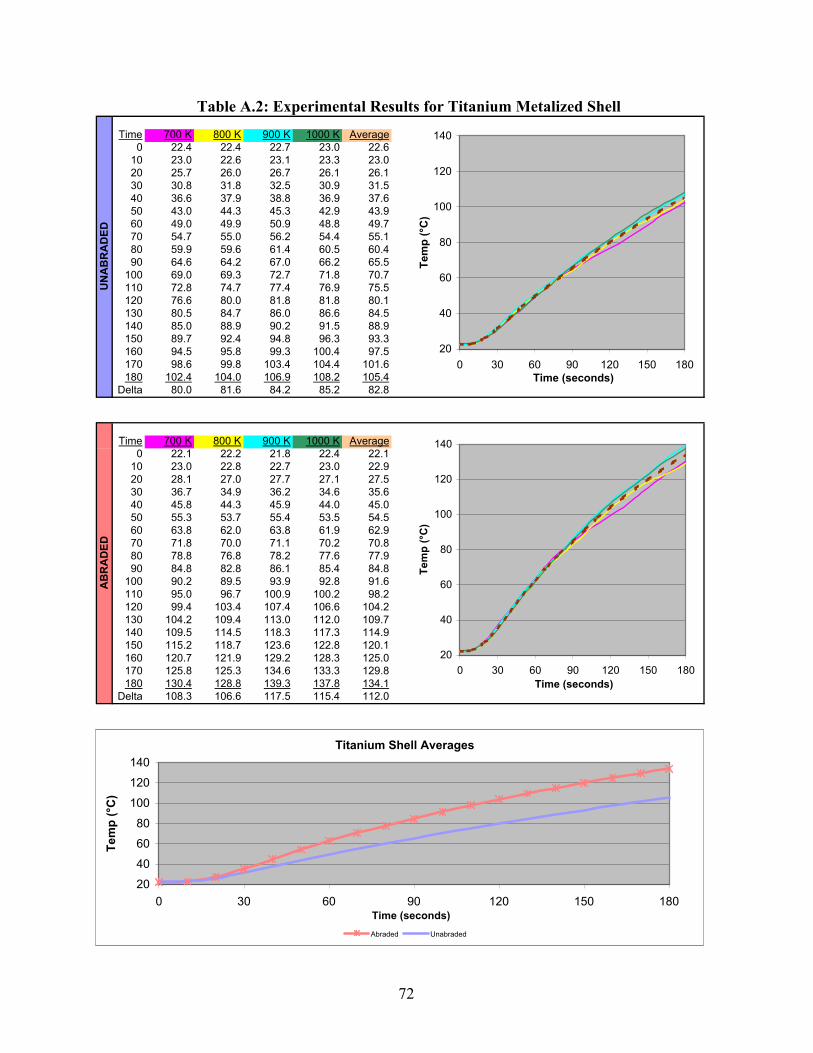
Time 700 K 800 K 900 K 1000 K Average0 22.4 22.4 22.7 23.0 22.6
10 23.0 22.6 23.1 23.3 23.020 25.7 26.0 26.7 26.1 26.130 30.8 31.8 32.5 30.9 31.540 36.6 37.9 38.8 36.9 37.650 43.0 44.3 45.3 42.9 43.960 49.0 49.9 50.9 48.8 49.770 54.7 55.0 56.2 54.4 55.180 59.9 59.6 61.4 60.5 60.490 64.6 64.2 67.0 66.2 65.5
100 69.0 69.3 72.7 71.8 70.7110 72.8 74.7 77.4 76.9 75.5120 76.6 80.0 81.8 81.8 80.1130 80.5 84.7 86.0 86.6 84.5140 85.0 88.9 90.2 91.5 88.9150 89.7 92.4 94.8 96.3 93.3160 94.5 95.8 99.3 100.4 97.5170 98.6 99.8 103.4 104.4 101.6180 102.4 104.0 106.9 108.2 105.4
Delta 80.0 81.6 84.2 85.2 82.8
Time 700 K 800 K 900 K 1000 K Average0 22.1 22.2 21.8 22.4 22.1
10 23.0 22.8 22.7 23.0 22.920 28.1 27.0 27.7 27.1 27.530 36.7 34.9 36.2 34.6 35.640 45.8 44.3 45.9 44.0 45.050 55.3 53.7 55.4 53.5 54.560 63.8 62.0 63.8 61.9 62.970 71.8 70.0 71.1 70.2 70.880 78.8 76.8 78.2 77.6 77.990 84.8 82.8 86.1 85.4 84.8
100 90.2 89.5 93.9 92.8 91.6110 95.0 96.7 100.9 100.2 98.2120 99.4 103.4 107.4 106.6 104.2130 104.2 109.4 113.0 112.0 109.7140 109.5 114.5 118.3 117.3 114.9150 115.2 118.7 123.6 122.8 120.1160 120.7 121.9 129.2 128.3 125.0170 125.8 125.3 134.6 133.3 129.8180 130.4 128.8 139.3 137.8 134.1
Delta 108.3 106.6 117.5 115.4 112.0
Table A.2: Experimental Results for Titanium Metalized ShellU
NA
BR
AD
EDA
BR
AD
ED
20
40
60
80
100
120
140
0 30 60 90 120 150 180Time (seconds)
Tem
p (°
C)
20
40
60
80
100
120
140
0 30 60 90 120 150 180Time (seconds)
Tem
p (°
C)
Titanium Shell Averages
20406080
100120140
0 30 60 90 120 150 180Time (seconds)
Tem
p (°
C)
Abraded Unabraded
72

Time 700 K 800 K 900 K 1000 K Average0 21.1 21.9 22.6 21.9 21.9
10 22.2 22.8 23.3 22.5 22.720 25.9 27.0 27.5 25.6 26.530 32.0 33.2 33.2 30.7 32.340 38.3 39.6 39.8 36.6 38.650 44.9 45.9 45.5 42.4 44.760 51.1 51.2 50.8 48.1 50.370 56.5 56.1 55.7 53.4 55.480 61.6 60.2 60.5 58.5 60.290 66.1 64.5 66.3 64.2 65.3
100 70.2 69.4 71.6 69.7 70.2110 73.6 74.7 76.3 74.7 74.8120 77.1 79.7 80.5 79.2 79.1130 80.6 83.9 84.3 83.4 83.1140 84.5 88.0 88.7 87.9 87.3150 89.1 91.3 92.9 92.6 91.5160 93.7 94.5 97.5 97.1 95.7170 97.8 98.1 101.0 100.8 99.4180 101.5 102.3 104.4 104.5 103.2
Delta 80.4 80.4 81.8 82.6 81.3
Time 700 K 800 K 900 K 1000 K Average0 20.5 21.6 21.4 21.9 21.4
10 21.6 22.9 22.4 23.6 22.620 26.9 28.9 28.1 30.7 28.730 35.1 38.3 36.9 40.7 37.840 45.2 47.8 46.6 50.8 47.650 54.8 56.8 55.3 59.8 56.760 64.1 64.5 63.1 67.6 64.870 72.3 71.3 70.0 75.5 72.380 79.7 77.3 77.3 83.3 79.490 86.2 83.1 84.9 91.0 86.3
100 92.0 90.0 92.2 98.6 93.2110 97.2 96.8 99.2 105.1 99.6120 101.9 103.4 104.6 110.9 105.2130 106.8 108.9 110.2 116.5 110.6140 111.6 113.7 115.2 122.4 115.7150 117.1 117.5 121.1 128.2 121.0160 122.6 120.4 127.0 133.2 125.8170 128.1 123.4 132.2 137.6 130.3180 132.8 127.4 136.6 141.6 134.6
Delta 112.3 105.8 115.2 119.7 113.3
Table A.3: Experimental Results for Electroless Copper Plated ShellU
NA
BR
AD
EDA
BR
AD
ED
20
40
60
80
100
120
140
0 30 60 90 120 150 180Time (seconds)
Tem
p (°
C)
20
40
60
80
100
120
140
0 30 60 90 120 150 180Time (seconds)
Tem
p (°
C)
E/M Copper Shell Averages
20406080
100120140
0 30 60 90 120 150 180Time (seconds)
Tem
p (°
C)
Abraded Unabraded
73

Time 700 K 800 K 900 K 1000 K Average0 22.4 21.8 23.8 23.3 22.8
10 23.0 22.0 24.8 23.9 23.420 26.5 25.5 28.6 28.1 27.230 32.4 31.0 34.1 33.8 32.840 38.6 37.3 40.0 39.8 38.950 45.2 43.2 45.6 45.7 44.960 51.0 48.6 50.5 50.8 50.270 56.5 53.9 55.3 56.3 55.580 61.5 58.1 60.4 61.5 60.490 66.2 62.6 65.7 67.0 65.4
100 70.1 67.7 70.6 72.4 70.2110 73.7 73.0 75.2 77.2 74.8120 77.5 78.2 79.3 81.6 79.2130 81.5 82.9 83.3 86.1 83.5140 86.1 86.9 87.2 90.8 87.8150 90.8 90.4 91.4 95.0 91.9160 95.0 94.0 95.3 98.8 95.8170 98.8 97.6 98.9 102.2 99.4180 102.0 101.6 102.2 105.7 102.9
Delta 79.6 79.8 78.4 82.4 80.1
Time 700 K 800 K 900 K 1000 K Average0 21.4 22.7 21.7 22.5 22.1
10 22.3 23.8 22.5 23.9 23.120 28.0 30.6 28.5 31.0 29.530 37.1 40.0 37.7 41.0 39.040 48.0 50.4 47.2 51.3 49.250 57.8 59.6 55.6 60.9 58.560 67.1 68.2 62.8 69.1 66.870 75.7 75.4 69.7 77.3 74.580 83.0 81.6 76.6 85.2 81.690 89.8 88.2 84.0 93.4 88.9
100 95.3 95.1 91.3 101.0 95.7110 101.0 102.4 98.0 107.4 102.2120 105.6 108.9 103.5 113.2 107.8130 108.2 114.5 108.4 118.6 112.4140 111.8 118.8 113.8 124.9 117.3150 114.7 122.3 119.3 130.2 121.6160 118.1 125.4 124.8 135.3 125.9170 120.6 128.8 129.8 139.8 129.8180 123.7 132.5 133.8 143.7 133.4
Delta 102.3 109.8 112.1 121.2 111.4
Table A.4: Experimental Results for Pewter Coated ShellU
NA
BR
AD
EDA
BR
AD
ED
20
40
60
80
100
120
140
0 30 60 90 120 150 180Time (seconds)
Tem
p (°
C)
20
40
60
80
100
120
140
0 30 60 90 120 150 180Time (seconds)
Tem
p (°
C)
Pewter Shell Averages
20406080
100120140
0 30 60 90 120 150 180Time (seconds)
Tem
p (°
C)
Abraded Unabraded
74

Time 700 K 800 K 900 K 1000 K Average0 21.3 21.9 22.0 22.0 21.8
10 22.1 22.3 22.5 23.1 22.520 24.2 24.0 24.4 25.2 24.530 27.2 26.6 27.2 28.2 27.340 30.6 29.2 30.1 31.5 30.450 34.3 31.8 33.1 34.6 33.560 37.5 34.2 35.8 37.5 36.370 40.6 36.4 38.3 40.6 39.080 43.5 38.5 40.8 43.5 41.690 46.3 40.7 43.8 46.5 44.3
100 48.8 43.2 46.8 49.6 47.1110 51.1 45.8 49.3 52.0 49.6120 53.2 48.2 51.8 54.6 52.0130 55.3 50.5 54.0 57.1 54.2140 57.6 52.5 56.3 59.9 56.6150 60.3 54.2 58.8 62.6 59.0160 63.1 56.3 61.3 64.9 61.4170 65.6 58.2 63.5 67.1 63.6180 68.0 60.4 65.3 69.4 65.8
Delta 46.7 38.5 43.3 47.4 44.0
Time 700 K 800 K 900 K 1000 K Average0 21.2 22.3 21.3 21.7 21.6
10 22.4 23.4 22.6 23.1 22.920 28.6 28.8 28.9 28.4 28.730 37.8 37.5 38.1 36.4 37.540 48.0 46.9 47.9 44.9 46.950 58.1 55.3 56.6 53.4 55.960 66.9 62.6 63.8 60.5 63.570 74.6 69.4 70.2 67.2 70.480 81.6 74.9 77.1 73.6 76.890 87.4 80.5 84.3 80.5 83.2
100 92.6 86.9 91.0 87.0 89.4110 97.0 93.4 97.1 92.6 95.0120 100.9 99.3 101.9 97.7 100.0130 105.0 104.5 105.9 102.4 104.5140 109.5 108.8 110.3 107.2 109.0150 114.6 112.3 114.7 111.9 113.4160 119.9 115.6 118.9 116.3 117.7170 124.7 119.8 122.7 120.1 121.8180 128.9 124.2 125.8 123.4 125.6
Delta 107.7 101.9 104.5 101.7 104.0
Table A.5: Experimental Results for Aluminum Painted ShellU
NA
BR
AD
EDA
BR
AD
ED
20
40
60
80
100
120
0 30 60 90 120 150 180Time (seconds)
Tem
p (°
C)
20
40
60
80
100
120
0 30 60 90 120 150 180Time (seconds)
Tem
p (°
C)
Mirror Aluminum Shell Averages
20
40
60
80
100
120
0 30 60 90 120 150 180Time (seconds)
Tem
p (°
C)
Abraded Unabraded
75

Time 700 K 800 K 900 K 1000 K Average0 20.9 21.6 22.8 22.2 21.9
10 21.3 21.7 23.0 22.5 22.120 21.6 22.0 23.2 22.7 22.430 22.2 22.6 23.7 23.1 22.940 22.8 23.2 24.2 23.6 23.550 23.5 23.8 24.8 24.2 24.160 24.2 24.3 25.3 24.6 24.670 24.7 24.9 25.7 25.1 25.180 25.1 25.3 26.2 25.6 25.690 25.8 25.8 26.7 26.1 26.1
100 26.4 26.3 27.2 26.6 26.6110 26.8 26.9 27.8 27.1 27.2120 27.2 27.5 28.2 27.6 27.6130 27.5 28.0 28.6 28.1 28.1140 28.0 28.6 29.1 28.6 28.6150 28.7 29.0 29.6 29 29.1160 29.2 29.4 30.1 29.6 29.6170 29.8 29.9 30.6 30 30.1180 30.5 30.4 31.0 30.5 30.6
Delta 9.6 8.8 8.2 8.3 8.7
Time 700 K 800 K 900 K 1000 K Average0 21.5 22.1 21.5 22.2 21.8
10 22.6 22.8 22.7 23.0 22.820 27.8 28.1 27.6 27.3 27.730 36.0 35.5 35.6 33.6 35.240 44.5 43.4 43.6 40.9 43.150 53.0 51.1 50.5 47.4 50.560 60.5 57.8 56.6 53.4 57.170 67.4 63.2 62.2 58.8 62.980 73.2 68.0 67.5 64.0 68.290 78.5 72.6 73.2 69.2 73.4
100 82.9 78.0 78.8 74.1 78.5110 86.9 83.4 83.8 78.5 83.2120 90.1 88.6 87.9 82.5 87.3130 92.9 92.8 91.5 86.0 90.8140 96.1 96.5 95.1 89.6 94.3150 99.5 99.3 99.3 93.5 97.9160 103.5 102.1 103.2 97.1 101.5170 107.6 105.2 107.0 100.0 105.0180 110.9 108.8 109.9 102.8 108.1
Delta 89.4 86.7 88.4 80.6 86.3
Table A.6: Experimental Results for Aluminum Vacuum Metalized ShellU
NA
BR
AD
EDA
BR
AD
ED
20
40
60
80
100
0 30 60 90 120 150 180Time (seconds)
Tem
p (°
C)
20
40
60
80
100
0 30 60 90 120 150 180Time (seconds)
Tem
p (°
C)
Vacuum Metalized Aluminum Shell Averages
20
40
60
80
100
0 30 60 90 120 150 180Time (seconds)
Tem
p (°
C)
Abraded Unabraded
76

Time 700 K 800 K 900 K 1000 K Average0 21.5 21.7 22.6 22.6 22.1
10 21.8 22.1 23.2 22.9 22.520 23.2 23.5 24.6 24.5 24.030 25.3 25.8 26.6 26.6 26.140 28.1 28.4 28.9 29.2 28.750 30.8 31.1 31.5 31.9 31.360 33.5 33.4 33.5 34.3 33.770 36.2 35.6 35.6 36.6 36.080 38.7 37.5 37.9 39.2 38.390 40.7 39.5 40.2 41.6 40.5
100 43.0 41.8 42.4 44.1 42.8110 44.8 44.1 44.8 46.4 45.0120 46.5 46.6 46.5 48.6 47.1130 48.2 48.7 48.3 50.6 49.0140 50.2 50.5 50.3 52.8 51.0150 52.3 52.2 52.3 55.0 53.0160 54.5 53.8 54.4 57.0 54.9170 56.7 55.6 56.1 58.9 56.8180 58.7 57.6 57.8 60.6 58.7
Delta 37.2 35.9 35.2 38.0 36.6
Time 700 K 800 K 900 K 1000 K Average0 21.9 21.6 21.3 22.4 21.8
10 22.3 22.6 22.0 22.9 22.520 24.4 24.9 23.9 25.4 24.730 27.9 28.3 27.0 28.7 28.040 32.0 32.0 30.3 32.5 31.750 36.0 35.7 33.8 35.8 35.360 40.1 38.8 36.6 38.8 38.670 43.6 41.7 39.3 42.1 41.780 46.9 44.0 42.2 45.2 44.690 49.9 46.6 45.5 48.4 47.6
100 52.9 49.7 48.5 51.3 50.6110 55.2 52.7 51.4 54.0 53.3120 57.6 55.5 53.6 56.5 55.8130 59.5 58.2 55.8 59.0 58.1140 61.8 60.3 58.3 61.8 60.6150 64.2 62.3 60.8 64.4 62.9160 66.7 64.0 63.3 66.7 65.2170 69.5 66.3 65.6 68.8 67.6180 72.0 68.6 67.6 70.6 69.7
Delta 50.1 47.0 46.3 48.2 47.9
Table A.7: Experimental Results for Aluminum Sputtered ShellU
NA
BR
AD
EDA
BR
AD
ED
20
30
40
50
60
70
80
0 30 60 90 120 150 180Time (seconds)
Tem
p (°
C)
20
30
40
50
60
70
80
0 30 60 90 120 150 180Time (seconds)
Tem
p (°
C)
ACS Aluminum Shell Averages
20304050
607080
0 30 60 90 120 150 180Time (seconds)
Tem
p (°
C)
Abraded Unabraded
77

Time 700 K 800 K 900 K 1000 K Average0 21.5 21.7 22.3 22.5 22.0
10 22.2 22.2 22.9 22.8 22.520 23.1 23.2 24.0 24.4 23.730 24.9 25.3 26.1 26.7 25.840 27.0 27.5 28.4 29.3 28.150 29.7 29.6 30.6 31.9 30.560 31.9 31.9 32.7 34.3 32.770 34.1 33.8 34.6 36.6 34.880 36.2 35.4 36.8 39.3 36.990 38.1 37.2 39.0 41.8 39.0
100 39.8 39.2 41.4 44.0 41.1110 41.3 41.5 43.6 46.3 43.2120 42.8 43.6 45.4 48.6 45.1130 44.5 45.4 47.2 50.7 47.0140 46.3 47.2 48.9 52.9 48.8150 48.3 48.7 51.0 55.2 50.8160 50.2 50.0 53.1 57.2 52.6170 52.3 51.7 54.9 58.9 54.5180 53.7 53.6 56.6 60.9 56.2
Delta 32.2 31.9 34.3 38.4 34.2
Time 700 K 800 K 900 K 1000 K Average0 21.0 22.2 21.2 22.0 21.6
10 21.8 22.6 21.8 22.5 22.220 23.0 23.5 22.8 23.2 23.130 25.3 25.5 24.9 25.0 25.240 27.8 27.7 27.2 27.2 27.550 30.6 29.9 29.5 29.5 29.960 33.2 32.0 31.7 32.0 32.270 35.8 34.0 33.8 34.3 34.580 38.3 35.6 35.7 36.5 36.590 40.2 37.4 38.0 38.8 38.6
100 42.3 39.6 40.3 41.4 40.9110 43.8 41.8 42.6 43.7 43.0120 45.6 43.8 44.6 45.9 45.0130 47.4 45.8 46.4 48.1 46.9140 49.0 47.5 48.2 50.0 48.7150 51.0 49.1 50.3 52.2 50.7160 53.1 50.5 52.3 54.4 52.6170 55.2 52.3 54.3 56.5 54.6180 56.9 54.0 55.9 58.3 56.3
Delta 35.9 31.8 34.7 36.3 34.7
Table A.8: Experimental Results for Nickel-Chrome Electroplated ShellU
NA
BR
AD
EDA
BR
AD
ED
20
30
40
50
60
0 30 60 90 120 150 180Time (seconds)
Tem
p (°
C)
20
30
40
50
60
0 30 60 90 120 150 180Time (seconds)
Tem
p (°
C)
Nickel-Chrome Shell Averages
20
30
40
50
60
0 30 60 90 120 150 180Time (seconds)
Tem
p (°
C)
Abraded Unabraded
78

Time 700 K 800 K 900 K 1000 K Average0 21.2 22.1 22.8 22.3 22.1
10 21.5 22.2 22.9 22.8 22.420 21.8 22.5 23.2 22.9 22.630 22.4 23.0 23.8 23.4 23.240 23.5 23.9 24.5 24.2 24.050 24.7 24.8 25.4 24.9 25.060 25.9 25.7 26.2 25.8 25.970 27.2 26.6 27.0 26.6 26.980 28.4 27.5 27.8 27.4 27.890 29.5 28.3 28.6 28.2 28.7
100 30.6 29.1 29.5 29.0 29.6110 31.6 30.0 30.3 29.9 30.5120 32.6 31.0 31.3 30.6 31.4130 33.5 31.9 31.9 31.4 32.2140 34.3 32.8 32.6 32.2 33.0150 35.1 33.6 33.4 33.0 33.8160 35.9 34.4 34.2 33.9 34.6170 36.8 35.0 35.0 34.6 35.4180 37.8 35.8 35.7 35.3 36.2
Delta 16.6 13.7 12.9 13.0 14.1
Time 700 K 800 K 900 K 1000 K Average0 22.3 21.9 21.0 22.4 21.9
10 22.4 22.2 22.0 22.8 22.420 22.7 22.4 22.1 22.9 22.530 23.6 23.0 22.5 23.4 23.140 25.3 23.8 23.2 24.1 24.150 26.9 24.8 24.0 25.0 25.260 28.7 25.9 24.9 25.9 26.470 30.7 26.8 25.8 26.8 27.580 32.5 27.8 26.8 27.8 28.790 34.4 28.7 27.7 28.7 29.9
100 35.9 29.7 28.8 29.7 31.0110 37.5 30.7 29.8 30.7 32.2120 39.0 31.8 30.8 31.7 33.3130 40.4 32.9 31.8 32.6 34.4140 41.8 33.9 32.8 33.5 35.5150 43.0 34.8 33.7 34.4 36.5160 44.3 35.7 34.7 35.4 37.5170 45.8 36.6 35.7 36.3 38.6180 47.4 37.5 36.6 37.1 39.7
Delta 25.1 15.6 15.6 14.7 17.8
Table A.9: Experimental Results for Aluminized Textile Shroud Covered ShellU
NA
BR
AD
EDA
BR
AD
ED
20
30
40
50
0 30 60 90 120 150 180Time (seconds)
Tem
p (°
C)
20
30
40
50
0 30 60 90 120 150 180Time (seconds)
Tem
p (°
C)
Aluminized Shroud Averages
20
30
40
50
0 30 60 90 120 150 180Time (seconds)
Tem
p (°
C)
Abraded Unabraded
79

APPENDIX B: EXPERIMENTAL TEST SPECIMEN PHOTOGRAPHS
Figure B.1: Stock White Thermoplastic Helmet Shell ............................................................... 81
Figure B.2: Titanium Metalized Helmet Shell ........................................................................... 82
Figure B.3: Electroless Copper Plated Helmet Shell ................................................................. 83
Figure B.4: Pewter Coated Helmet Shell ................................................................................... 84
Figure B.5: Aluminum Painted Helmet Shell ............................................................................ 85
Figure B.6: Aluminum Vacuum Metalized Helmet Shell .......................................................... 86
Figure B.7: Aluminum Sputtered Helmet Shell ......................................................................... 87
Figure B.8: Nickel-Chrome Electroplated Helmet Shell ........................................................... 88
Figure B.9: Aluminized Textile Shroud Covered Helmet Shell ................................................ 89
80

Figure B.1: Stock White Thermoplastic Helmet Shell
81

Figure B.2: Titanium Metalized Helmet Shell
82

Figure B.3: Electroless Copper Plated Helmet Shell
83

Figure B.4: Pewter Coated Helmet Shell
84

Figure B.5: Aluminum Painted Helmet Shell
85

Figure B.6: Aluminum Vacuum Metalized Helmet Shell
86

Figure B.7: Aluminum Sputtered Helmet Shell
87

Figure B.8: Nickel-Chrome Electroplated Helmet Shell
88

Figure B.9: Aluminized Textile Shroud Covered Helmet Shell
89

APPENDIX C: ABRADED EXPERIMENTAL TEST SPECIMEN PHOTOGRAPHS
Figure C.1: Abraded Stock White Thermoplastic Helmet Shell ................................................ 91
Figure C.2: Abraded Titanium Metalized Helmet Shell ........................................................... 92
Figure C.3: Abraded Electroless Copper Plated Helmet Shell .................................................. 93
Figure C.4: Abraded Pewter Coated Helmet Shell .................................................................... 94
Figure C.5: Abraded Aluminum Painted Helmet Shell ............................................................. 95
Figure C.6: Abraded Aluminum Vacuum Metalized Helmet Shell ........................................... 96
Figure C.7: Abraded Aluminum Sputtered Helmet Shell .......................................................... 97
Figure C.8: Abraded Nickel-Chrome Electroplated Helmet Shell ............................................ 98
Figure C.9: Abraded Aluminized Textile Shroud Covered Helmet Shell ................................. 99
90

Figure C.1: Abraded Stock White Thermoplastic Helmet Shell
91

Figure C.2: Abraded Titanium Metalized Helmet Shell
92

Figure C.3: Abraded Electroless Copper Plated Helmet Shell
93

Figure C.4: Abraded Pewter Coated Helmet Shell
94

Figure C.5: Abraded Aluminum Painted Helmet Shell
95
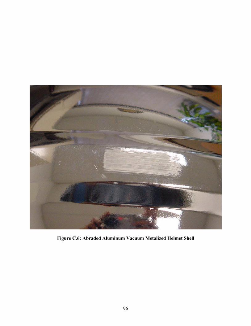
Figure C.6: Abraded Aluminum Vacuum Metalized Helmet Shell
96

Figure C.7: Abraded Aluminum Sputtered Helmet Shell
97

Figure C.8: Abraded Nickel-Chrome Electroplated Helmet Shell
98

Figure C.9: Abraded Aluminized Textile Shroud Covered Helmet Shell
99

BIBLIOGRAPHY
1. American Institute of Physics, “American Institute of Physics Handbook”, McGraw-Hill, New York, New York, 1972.
2. Bejan, Adrian, “Convection Heat Transfer”, John Wiley & Sons, Inc., New York, New
York, 1995.
3. Cox, Geoffrey, "Combustion Fundamentals of Fire," Academic Press, San Diego, CA, 1995
4. Del Vecchio, R.J., “Understanding Design of Experiments”, Hanser/Gardner
Publications, Cincinnati, Ohio, 1997.
5. GE Plastics Product Data Catalog, General Electrics Plastics, Pittsfield, Massachusetts, 2000.
6. Gentex Dual Mirror Aluminized Fabrics Catalog, Gentex Corporation, Carbondale,
Pennsylvania, 1999.
7. Karlsson, Björn, Quintiere, James G., "Enclosure Fire Dynamics," CRC Press, Boca Raton, FL, 2000
8. King, R.G., "Surface Treatment and Finishing of Aluminum," Pergamon Press, Oxford,
England, 1988
9. Incropera, F.P., Dewitt, D.P., “Fundamentals of Heat and Mass Transfer,” Second Edition, John Wiley & Sons, New York, 1985.
10. Ingram, Arthur, “A History of Fire-Fighting and Equipment”, Chartwell Books Inc.,
Secaucus, New Jersey, 1978.
11. Lide, David R., "CRC Handbook of Chemistry and Physics, 79th Edition," CRC Press, Boca Raton, FL, 1998
12. Lindeburg, Michael R., “Mechanical Engineering Reference Manual”, Tenth Edition,
Professional Publications, Inc., Belmont, CA, 1997.
13. Mell, W.E., Lawson, J.R., “A Heat Transfer Model for Firefighters’ Protective Clothing”, Fire Technology, Vol. 36, No. 1, 2000, pp. 39-68.
14. Melles Griot, “Optics Guide 2”, Melles Griot Optical Components Division, Irvine,
California, 1982.
15. Modest, Michael F., “Radiative Heat Transfer”, McGraw-Hill, New York, New York, 1993.
100

101
16. National Fire Protection Association, “NFPA 1981-1997: Standard on Open-Circuit Self-
Contained Breathing Apparatus for the Fire Service”, National Fire Protection Association, Quincy, Massachusetts, 1997.
17. National Fire Protection Association, “NFPA 1976-2000: Protective Ensemble for
Proximity Fire Fighting”, National Fire Protection Association, Quincy, Massachusetts, 2000.
18. National Fire Protection Association, “NFPA 1971-2000: Protective Ensemble for
Structural Fire Fighting”, National Fire Protection Association, Quincy, Massachusetts, 2000.
19. Oberg, E., Franklin, J.D., Horton, H.L., Ryffell, H.H., “Machinery’s Handbook”, 26th
Edition, Industrial Press, New York, 2000.
20. Ozisik, M.N., “Boundary Value Problems of Heat Conduction,” International Textbook Company, Scranton, Pennsylvania, 1968.
21. Ozisik, M.N., “Radiative Transfer and Interactions with Conduction and Convection,”
John Wiley & Sons, New York, 1973.
22. Siegel, Robert, Howell, John R., "Thermal Radiation Heat Transfer, Third Edition," Hemisphere Publishing Corporation, Washington D.C., 1992
23. Strahle, Warren C., “An Introduction to Combustion”, Gordon and Breach Publishers,
Amsterdam B.V., The Netherlands, 1993.
24. Zerkle, R.D., Sunderland, J.E., “The Transient Temperature Distribution in a Slab Subject to Thermal Radiation”, Journal of Heat Transfer, February 1965, pp. 117-130.

VITA
David Louis Barnett was born in Kokomo, Indiana, USA on January 8, 1972. Living the first
eighteen years of his life in that city, he graduated from Kokomo High School in 1990 and
enrolled at Purdue University that same year. In December of 1993, David received a Bachelor
of Science Degree in Mechanical Engineering from Purdue.
David began his professional career in 1993 at Consolidated Industries Corporation in Lafayette,
Indiana. After two years at this firm, working as a Manufacturing Engineer, he moved on and
accepted a position at Delco Electronics (now Delphi Automotive) in Kokomo, Indiana. After a
two-year tenure as a Manufacturing Engineer at Delco, David relocated to central Kentucky and
assumed a position at E.D. Bullard Company. David received his Professional Engineering
License from the Commonwealth of Kentucky in 1998.
102