evaluation of mine seals using ground penetrating radar
TRANSCRIPT

EVALUATION OF MINE SEALS USING GROUND PENETRATING RADAR
William D. Monaghan Michael A. Trevits Michael J. Sapko
NIOSH, Pittsburgh Research Laboratory Pittsburgh, PA
Abstract
Mine seals are used extensively in underground coal mines to segregate mined-out areas and to isolate fire zones or underground areas that are susceptible to spontaneous combustion. Over the years, 30,000 mine seals have been erected in underground coal mines in the United States. Mine seals, along with rock dusting and ventilation, represent the fundamental means of preventing underground coal mine explosions. In this study the National Institute for Occupational Safety and Health (NIOSH) used ground penetrating radar (GPR) technology to determine if each of three test mine seals were uniformly constructed. Three mine seals representing different construction methods and materials (cast-in-place foamed cement; solid block, polyurethane foam and gravel; and wire mesh, rebar and gunite) were erected at the NIOSH Lake Lynn Laboratory’s underground mine as part of an on-going research program. The seals were imaged using GPR with 400-, 500-, 900-, and 1,000-MHz antennas. We found that variations in uniformity existed in the material for the cast-in-place foamed cement seal. Variations in uniformity also existed in the seal made from solid block, polyurethane foam and gravel. The post-processed radar records correlated closely with recovered core samples (areas of gravel and polyurethane foam, and areas containing only polyurethane foam). Finally, the radar records of the seal made of wire mesh, rebar and gunite showed the various components. The results of this work suggest that GPR could be used as a tool to evaluate mine seal characteristics and construction uniformity.
Introduction
Over the years, 30,000 seals have been erected in underground coal mines in the United States. Seals, along with rock dusting and ventilation, constitute the dominant portion of the last line of defense against underground coal mine explosions. Explosion-resistant underground mine ventilation seals serve several functions including protection from propagating explosions and separation of air between active and worked out mine areas (Weiss, 1993). Seals are also used to isolate active fire zones or areas susceptible to spontaneous combustion. (Sapko, 2003). During the 1990s, seven documented explosions of methane and/or coal dust occurred within sealed areas of underground U.S. coal mines (Hurren, 1993; Scott, 1996). These explosions, believed to be initiated by lightning strikes on the surface, destroyed several seals and caused considerable damage in the active underground mine workings. Fortunately, these explosions did not cause fatalities or injuries. However, the potential for a disaster exists, emphasizing the need for explosion-resistant seals that can perform under various mining and environmental conditions (Sapko, 2003). In order for seals to perform as expected, their as-built condition must conform to the engineering design specifications. Title 30, Part 75.335 of the U.S. Code of Federal Regulations (CFR) states that abandoned areas of underground coal mines must be either ventilated or isolated from active workings through the

use of seals capable of withstanding a static horizontal pressure of 20 psi (Code of Federal Regulations, 2004). To effectively isolate areas within a mine, a seal should be designed to control the methane gas and air exchange between the sealed and open areas so as to prevent toxic and/or flammable gases from entering the active workings. A seal must also be capable of preventing an explosion from propagating into or out of the sealed area. NIOSH has evaluated the use of a chamber technique for pressure loading full-size seals using compressed air, water, or confined gas explosions (Sapko, 2003). The end-product of this research effort is the development of alternative methodologies to better characterize the strength properties of mine seals and their ultimate interaction within the surrounding mine strata (NIOSH, 2002). Currently, no reliable method exists to inspect or confirm the condition of an erected mine seal underground without drilling or dismantling a portion of the seal and jeopardizing its structural integrity. Ground penetrating radar (GPR) has been used in agricultural, archeological, construction, environmental, forensic, geological, groundwater, military, and mining applications (Olhoeft, 2004)1. In some cases, GPR is used as a non-invasive method to examine the as-built conditions of structures. A GPR system generates an electromagnetic pulse that is transmitted into the ground with an antenna that is moved along the surface, generally at a uniform speed and direction. Whenever there is a change in the dielectric constant of the subsurface material, a portion of the pulse energy is reflected back to the surface and is detected by the receiving antenna. This reflected pulse provides information about changes in electrical properties of the subsurface material. The recorded two-way travel time is determined by measuring the time interval between the start of the transmit pulse and start of the received reflected signal. The amplitude of the reflected signal is influenced by the material type, size and geometry of the target, the signal attenuation characteristics of the material, and the total distance that the pulse has to travel. In this study, GPR was used as a non-invasive means of evaluating mine seal construction uniformity. The equipment used was a GSSI SIR® System 2 (SIR-2) Model No. DC-2 control unit built by Geophysical Survey Systems, Inc.2 The SIR-2 is a lightweight, portable, general-purpose radar system and is available as an intrinsically safe unit for use in the underground coal mine environment (figure 1).
The reflected pulse is processed by the control unit and the data are displayed on the monitor and stored on an internal hard disk. The output display can be (1) a single wiggle trace (analogous to an oscilloscope trace), (2) a waterfall plot of the wiggle traces, or (3) a multicolored line scan in which the reflected signal amplitudes are represented by various colors according to a user-selected color look-up table. During this study, the dielectric constant was adjusted in the SIR-2 unit until the arrival time of the reflected signal (expressed in term of depth) approximated the thickness of the mine seal. As a result of the tests, a dielectric constant of 4.5 was used for Mine Seal Nos. 1 and 2 and a dielectric constant 6.0 was used for .
Figure 1.: Engineer using the SIR-2 unit1 Additional information on GPR can be found the Internet using search terms such as “ground penetrating radar”, “GPR”, “georadar”, “ground probing radar”, “subsurface radar” etc. 2Mention of a specific product or trade name does not imply endorsement by NIOSH.

Mine Seal No. 3. The GPR records generated during this study were analyzed using GSSI’s Radar Data Analyzer for Windows (RADAN) version 6.02. This package allows the user to operate in the Windows environment with application-specific modules (GSSI, 2004).
Objective and Approach
The objective of our work was to determine if GPR could be used to detect changes in the composition of three Mine Safety & Health Administration approved type of mine seals that could potentially indicate areas of structural weakness. We approached this problem by using four shielded antennas whose frequency spectra produced pulses centered at near 400-, 500-, 900-, and 1,000-MHz. These antennas were selected because they could provide the required depth of penetration with the necessary resolution, are relatively lightweight, and could be easily positioned and moved along the face of the seals.
The mine seals were constructed in the NIOSH Lake Lynn Experimental Mine (LLEM). The Lake Lynn Laboratory (LLL) is a unique research facility, located about 50 miles southeast of Pittsburgh, Pennsylvania, that is designed to provide a full-scale mining environment for the testing and evaluation of mine health and safety technologies. The LLL occupies more than 400 acres and is composed of surface test and training areas and an underground mine (figure 2).
The LLEM was built at an abandoned commercial limestone quarry where underground entries 49-ft wide by 33-ft high (old workings) were developed when surface mining ceased in the late 1960's. Later, under the auspices of the U.S. Bureau of Mines, 7,545 ft of new underground development was constructed using 19.7-ft wide by 6.6-ft high entries (new workings). The new workings can be configured to simulate modern-day coal mining scenarios; including room-and-pillar and longwall mining layouts (NIOSH 1999, Triebsch, 1990) (figure 3).
Figure 2.: Photo of the Lake Lynn Laboratory. Various test areas are shown (buildings and open areas). The red circle shows the main entrance to the underground mine.
Two large-scale underground chambers were constructed in the mine to conduct pneumatic,
hydrostatic, or explosion pressure loading of mine seals. The large chamber measures 29.9-ft wide by 16.1-ft high by 10.2-ft deep with a maximum cross-sectional area of 481.4 ft2. The smaller of the two chambers is 20-ft wide by 8-ft high by 10.2 ft deep and can accommodate a seal design with a cross-sectional area up to 160 ft2 (Sapko, 2001).

Figure 3.: Layout of the Lake Lynn Laboratory Mine.
Mine Seal No. 1 Mine Seal No. 1, a cast-in-place foamed cement seal, was constructed in the large chamber in the LLEM and building the form was the first step in the construction process. The vertical components of the front and back portions of the form were built from 6.5-in by 5-in posts that extended from the mine floor to roof. A post was placed at both ribs and additional posts were spaced between the rib posts on 35-in centers. The void space behind the posts in the chamber was 8-ft on the left side and 6-ft on the
right side. Next, 8-in wide by 1-in thick boards were placed in a horizontal position and were nailed to each post (figure 4). The boards were placed at the bottom of the form and an 8-in horizontal space was left between each row of boards. This procedure was followed on the front and back walls of the form. Fiberglass insulation was then packed into any void space on the mine roof, ribs, and floor areas to minimize slurry leakage around the form. A 48.5-in space was left by design between the front and back walls of the form for the mine seal. Mine brattice cloth was placed on the inside area of the form, was overlapped on the mine roof and rib areas, and was secured with straps to form a tight seal. Eye bolts were then attached to each post through the brattice cloth and were tied together with 1/8-in galvanized steel cable that was extended
Tea
Figure 4.: Photo of inside of Mine Seal No. 1 showing the wooden form.
between the front and back of the form (figure 5). he eye bolts were spaced approximately 32-in apart on each post and were used throughout the vertical xtent of the form. The eye bolts and cable served to tie the front and back walls of the form together nd assisted in keeping the walls parallel and straight.

The mine seal was constructed in a series of three lifts over a three-day period. The seal mixture used was made of 18 gallons of foam concentrate, approximately 436 gallons of water and 989 bags of Quikrete2 cement. The water and foam concentrate was mixed together and was added to the cement at a rate of 8.5 gpm. The resulting slurry was then pumped into the form. The first lift was poured to a height of 72.5-in above the mine floor and was left to set overnight. The next day, before the second lift was poured, it was observed that a hard surface had formed at the top of the lift. The second lift was poured to a height of 77.5-in (or 150-in above the mine floor) using the same mixing procedure and was also allowed to set overnight. Anoticed that a hard surface had formed at the top of the sethe same procedure as the first two lifts to fill the remainindimensions of the resulting mine seal were 29.9-ft wide by
The seal material was cured for 33 days before the
gain direct access to the face of the seal, three vertical brattice cloth. The three vertical sections were approximfrom the mine floor to roof. Three vertical GPR surveshown in figure 6. The vertical sections were located at 4the right rib near the middle of the seal (line 2), and 4-ft frwas subdivided into one-foot segments for use as reference
GPR Evalu
The two parts beinitial portiomine floor aextended frSince the thdecided to image the determined the entire tfurther. Alseal were because of setup param500-MHz an
Figure 6.: Photo of mine seal No. 1 and location of GPR survey lines.
A total of 25 surveys were made of the mine seal.
against the seal face and then moving downward at a con
Figure 5.: Photo of inside of mine seal No. 1 before foamed cement was added.
s had been observed the previous day, it was cond lift. The third lift was constructed using g 43.2-in space to the mine roof. The overall 16.1-ft tall by 4-ft thick.
GPR evaluation was performed. In order to sections were cut into the wooden form and ately 8-in wide and exposed the seal material y lines were positioned along these sections -ft from the left rib (line 1), about 12-ft from om the right rib (line 3). Each vertical section points during the GPR evaluation.
ation
GPR survey of each section was conducted in cause of the excessive height of the seal. The n of each GPR survey line extended from the rea to a height of 8-ft and the second portion
om a height of 8-ft to the mine roof (16.1-ft). ickness of the mine seal was known, it was use 400-, 500-, and 900-MHz antennas to seal. After a short series of tests, it was that the 900-MHz antenna could not penetrate hickness of the mine seal and was not used so, surveys of the lower section of the mine only conducted with the 400-MHz antenna technical problems with the antenna. The eters used for each survey using the 400-and tennas are shown in table 1.
Each survey was made by placing the antenna stant velocity. Reference points were placed
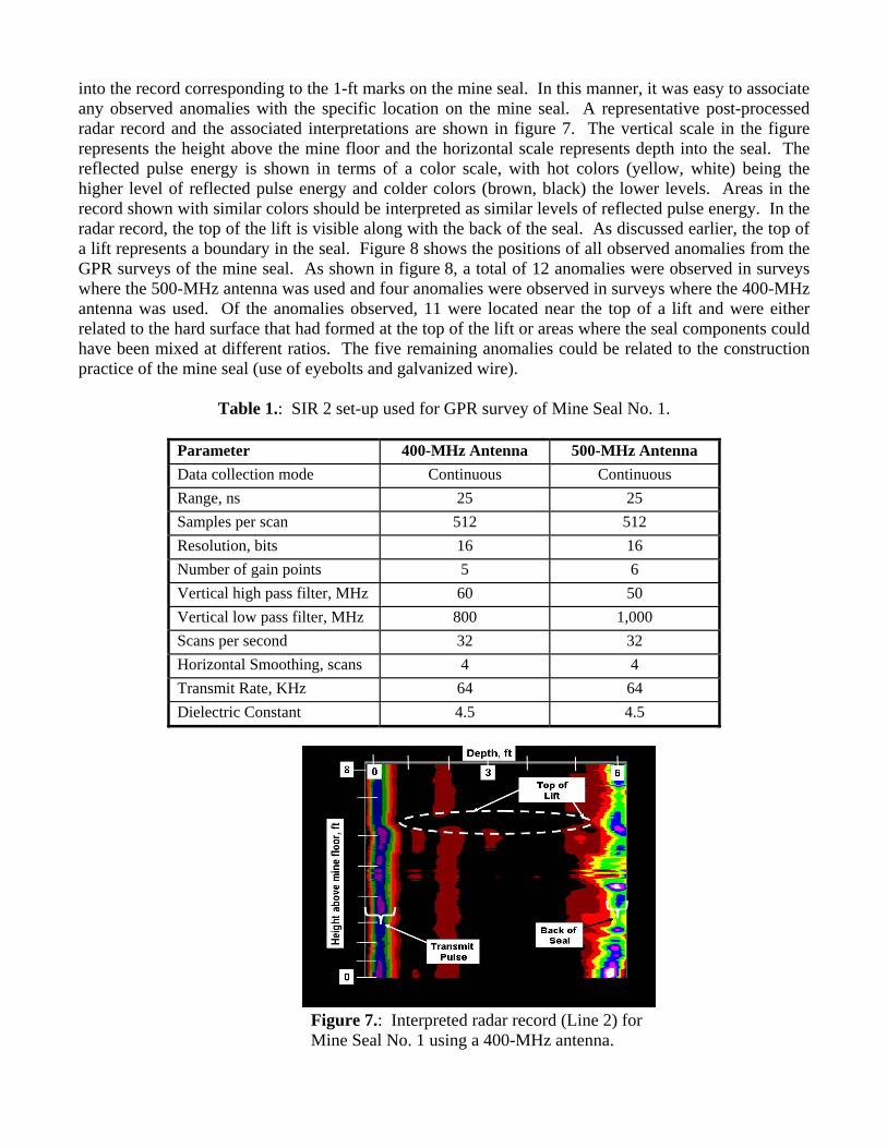
into the record corresponding to the 1-ft marks on the mine seal. In this manner, it was easy to associate any observed anomalies with the specific location on the mine seal. A representative post-processed radar record and the associated interpretations are shown in figure 7. The vertical scale in the figure represents the height above the mine floor and the horizontal scale represents depth into the seal. The reflected pulse energy is shown in terms of a color scale, with hot colors (yellow, white) being the higher level of reflected pulse energy and colder colors (brown, black) the lower levels. Areas in the record shown with similar colors should be interpreted as similar levels of reflected pulse energy. In the radar record, the top of the lift is visible along with the back of the seal. As discussed earlier, the top of a lift represents a boundary in the seal. Figure 8 shows the positions of all observed anomalies from the GPR surveys of the mine seal. As shown in figure 8, a total of 12 anomalies were observed in surveys where the 500-MHz antenna was used and four anomalies were observed in surveys where the 400-MHz antenna was used. Of the anomalies observed, 11 were located near the top of a lift and were either related to the hard surface that had formed at the top of the lift or areas where the seal components could have been mixed at different ratios. The five remaining anomalies could be related to the construction practice of the mine seal (use of eyebolts and galvanized wire).
Table 1.: SIR 2 set-up used for GPR survey of Mine Seal No. 1.
Parameter 400-MHz Antenna 500-MHz Antenna Data collection mode Continuous Continuous Range, ns 25 25 Samples per scan 512 512 Resolution, bits 16 16 Number of gain points 5 6 Vertical high pass filter, MHz 60 50 Vertical low pass filter, MHz 800 1,000 Scans per second 32 32 Horizontal Smoothing, scans 4 4 Transmit Rate, KHz 64 64 Dielectric Constant 4.5 4.5
Figure 7.: Interpreted radar record (Line 2) forMine Seal No. 1 using a 400-MHz antenna.

Mine Seal No. 2
Figure 8.: Location of observed anomalies from radar scans of mine seal No. 1.
Mine seal No. 2, a solid block, polyurethane foam, and gravel seal, was erected in the small chamber in the LLEM. The seal was constructed 8-ft high by 20-ft wide and about 2.5-ft thick. The seal was not hitched into the mine roof, rib or floor areas. The seal was built using two parallel walls of solid blocks with a 17.5-in open space between the walls. The walls were constructed with dry-stacked solid blocks (each measuring 6-in by 8-in by 16-in) and was capped by 2-in by 8-in by 16-in blocks and wedges at the mine roof (figure 9).
The open space between the block walls was filled in a series of lifts using gravel and polyurethane foam. The polyurethane
material was poured into the gravel bed and was supposed to infiltrate the gravel bed before it began to foam. By design, as the resin turned to foam, it was supposed to pick-up and disperse gravel in the resulting matrix. For each lift, gravel was placed to a depth of 10- to 12-in. Polyurethane resin was then poured over the gravel bed at a rate of about 2.5 gpm and the resulting foam rose to a height of about 10-in above the level of the gravel bed (figure 10). The core of the seal was constructed in 7 lifts over a 5.5-day period and any remaining open space above the lifts was then closed to the mine roof using injected polyurethane foam. In all, the seal was built using 292 blocks, 10,350 lbs of limestone and 2,000 lbs of polyurethane resin. Once the inner portions of the seal were built, the exposed face of the seal was coated with B-Bond2 to a maximum thickness of 0.25-in.
GPR Evaluation
GPR was used to determine if the gravel had been evenly dispersed throughout the mine seal. For the radar survey, two parallel vertical GPR survey lines were drawn on the mine seal face and were positioned about 6 ft from each mine rib (figure 11). Reference points (labeled A-F), spaced about 18-in apart, were then placed on the seal and were added to the radar records for comparative purposes. Each survey was made by placing the antenna against the seal face and then slowly moving downward at a constant velocity. The radar survey of the seal was made using 1,000-MHz antenna because this antenna
Figure 9.: Photo of solid block walls for Mine Seal No. 2.

provided the necessary depth of penetration and the desired level of resolution. A total of 52 surveys were made of the mine seal. Table 2 shows the setup parameters used for each survey.
ihss
Ie
Figure 10.: Photo of inner core of Mine Seal No.2 during addition of polyurethane resin.
Table 2.: SIR 2 set-up used for G
Parameter Data collection mode Range, ns Samples per scan Resolution, bits Number of gain points Vertical high pass filter, MHz Vertical low pass filter, MHz Scans per second Horizontal Smoothing, scans Transmit Rate, KHz Dielectric Constant
Figures 12 and 13 show two representativenterpretations. Reflected pulse energy is shown iighest level of reflected pulse energy and near-blimilar gray tones should be interpreted as similar lhown in the figures corresponds to the reference poi
In the radar records (figures 12 and 13), it is t was hypothesized that the area between the blocknergy because of the concentration of gravel in the
Figure 11.: Photo of Mine Seal No. 2 showing GPR survey lines.
PR survey of Mine Seal No. 2.
1,000-MHz Antenna Continuous
16 512
8 4
250 2000 32 4 64 6.0
post-processed radar records and their associated n terms of a grayscale, with near-white being the ack the lowest. Areas in the record shown with evels of reflected pulse energy. The vertical scale nts (labeled A-F) shown in figure 11.
possible to see both the front and back block walls. walls showed varying amounts of reflected pulse polyurethane foam was most likely not consistent

throughout the seal. To confirm this hypothesis, several large coreholes (6- by 18-in) were drilled into the seal after the GPR study was completed (figure 14). For this work, the block face of the seal was removed to facilitate core recovery. Figure 15 shows an example of a recovered core sample. This sample clearly shows a lift boundary and a detailed analysis of this core sample showed that the gravel was not evenly dispersed in the polyurethane foam. This confirms the hypothesis made from the radar records.
Figure 12.: Interpreted radar record for Mine Seal No. 2, Line 1.
Figure 13.: Interpreted radar record for Mine Seal No. 2, Line 2.

Figure 14.: Photo of Mine Seal No. 2 showing location of coreholes.
Mine Seahigh by 20-ft widmesh panels. Th(rebar) that was rebar that were asections of rebar Riregrete2 gunite
Figure 15.: Photo of recovered core sample from Mine Seal No. 2. Refer to figure Nos. 13 and 14.
Mine Seal No. 3
l No. 3 was erected in the small chamber in the LLEM. The seal was constructed 8-ft e and 11-in thick and was built using Stayfoam2 panel backing and Insteel 3D2 wire e panels were anchored to the mine roof rib and floors with No. 8 reinforcing bar
drilled and set into the exposed strata. Across the front of the seal, the segments of nchored into the roof and floor strata were affixed with steel strapping to vertical
and the wire mesh panels (figure 16). The entire face of the seal was then sprayed with to complete the construction.

Figure 16.: Photo of Mine Seal No. 3 showing the mesh panels and reinforcing bars.
GPR Evaluation
GPR was used to determine if the metal construction components could be resolved. For the radar survey, three perpendicular horizontal lines (lines 1-3) were positioned on the seal with the first line located about 6-in below the mine roof interface and the remaining two lines spaced about 24-in apart. In addition, two vertical lines (lines 4-5) were positioned approximately 4-ft from each mine rib. Reference points, spaced 24-in apart, were added to each survey line and these points were also added to the radar records (figure 17). Each survey was made by placing the antenna against the seal face and then moving along the line at a constant velocity. The radar survey of the seal were made using 1,000-MHz antenna because this antenna could provide the necessary depth of penetration and the desired level of resolution. A total of 22 surveys were made of the mine seal and table 3 shows the setup parameters used for each survey.
Figures 18 and 19 show representative post-processed radar records of Mine Seal No. 3 and their associated interpretations. The reflected pulse energy is shown in terms of a color scale, with hot colors (yellow and bright green) being the higher level of reflected pulse energy and colder colors (brown and black) the lower levels. Areas in the record shown with similar colors should be interpreted as similar levels of reflected pulse energy. The vertical scale shown in the figure corresponds to the
Figure 17.: Photo showing Mine Seal No. 3 with GPR survey lines.
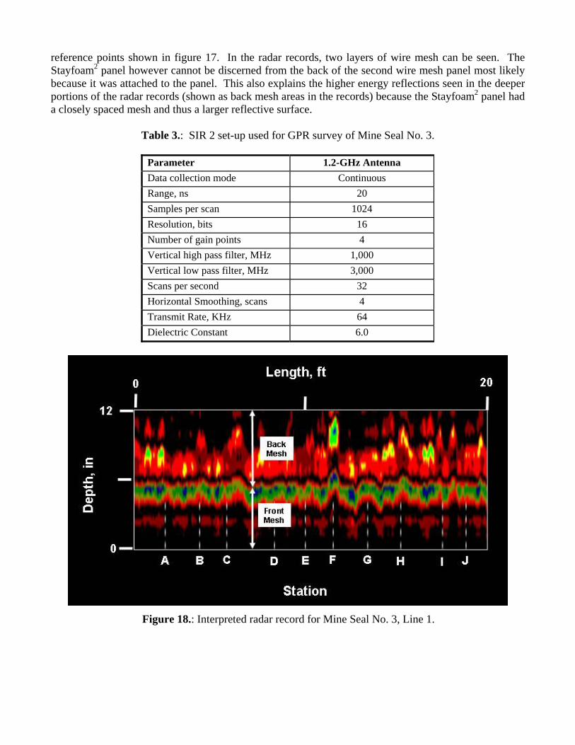
reference points shown in figure 17. In the radar records, two layers of wire mesh can be seen. The Stayfoam2 panel however cannot be discerned from the back of the second wire mesh panel most likely because it was attached to the panel. This also explains the higher energy reflections seen in the deeper portions of the radar records (shown as back mesh areas in the records) because the Stayfoam2 panel had a closely spaced mesh and thus a larger reflective surface.
Table 3.: SIR 2 set-up used for GPR survey of Mine Seal No. 3.
Parameter 1.2-GHz Antenna Data collection mode Continuous Range, ns 20 Samples per scan 1024 Resolution, bits 16 Number of gain points 4 Vertical high pass filter, MHz 1,000 Vertical low pass filter, MHz 3,000 Scans per second 32 Horizontal Smoothing, scans 4 Transmit Rate, KHz 64 Dielectric Constant 6.0
Figure 18.: Interpreted radar record for Mine Seal No. 3, Line 1.

Figure 19.: Interpreted radar record for Mine Seal No. 3, Line 3.
Summary and Conclusions
In this study, GPR technology was used to determine if mine seal construction materials could be
non-invasively inspected in place. Three mine seals that were built of widely different materials were evaluated at the NIOSH Lake Lynn Laboratory Experimental Mine. An analysis of the resulting radar records for each seal shows that GPR can indeed be used to delineate mine seal components. The results of this work suggests that mine seals could be evaluated using GPR to determine if the seal was constructed as designed with all seal components in place. The study implies that GPR can also be used to identify material uniformity and anomalies within a seal that could indicate areas of structural weakness. Finally, it is suggested that additional research should be conducted to determine if GPR can be used to assess mine seal integrity and possibly delineate the effects of long-term exposure to underground mine conditions (internal fracturing or cracking caused by roof-to-floor convergence which may not be determined by visual inspection of the face of the seal).
References
Code of Federal Regulations, 2004, Title 30–Mineral Resources, Chapter I–Mine Safety and Health Administration Department of Labor, Part 75–Mandatory Safety Standards–Underground Coal Mines, Subpart D–Ventilation Sec. 75.335 Construction of Seals. Geophysical Survey Systems, Inc. (GSSI), 2004, RADAN 6 Users Manual, MN43-171, p. 135.

Hurren W.E., G. N. Tuggle, and F. I. McGruder. Mary Lee No. 1 Mine, Accident Investigation Report (Underground Coal Mine) U.S. Labor Dept. MSHA, August 22, 1993. National Institute for Occupational Safety and Health (NIOSH), 1999, Lake Lynn Laboratory (flyer), Pittsburgh, PA: U.S. Department of Health and Human Services, Public Health Service, Centers for Disease Control and Prevention, National Institute for Occupational Safety and Health, DHHS (NIOSH) Publication No. 99-149, 1 p. National Institute for Occupational Safety and Health, 2002, A compendium of NIOSH Mining Research 2002, Washington, DC: U.S. Department of Health and Human Services, Public Health Service, Centers for Disease Control and Prevention, National Institute for Occupational Safety and Health, DHHS (NIOSH), Publication No. 2002-110, p. 73. Olhoeft, G.R., 2004, Ground Penetrating Radar, Home Page, November 26, 2004 , http://www.g-p-r.com. Sapko M.J. and Weiss E.S., Evaluation of new methods and facilities to test explosion-resistant seals. Proceedings of the 29th International Conference of Safety in Mines Research Institutes, Katowice, Poland, October 8-11, 2001, Vol. 1, pp. 157-166. Sapko, M. J., Weiss, E. S., Harteis, S. P. Alternative Methodologies for Evaluating Explosion-Resistant Mine Ventilation Seals. Proccedings of the 30th International Conference of Safety in Mines Research Institutes, South African Institute of Mining and Metallurgy, October 2003, pp. 615-640. Scott, D. S., E. L. Checca., C. R. Stephen, and M. J. Schultz., Oak Grove Mine, I.D. No. 01-00851, Accident Investigation Report, U.S. Labor Dept. MSHA, January 29,1996. Triebsch, G.F. and M.J. Sapko, 1990, Lake Lynn Laboratory: A State-of-the-Art Mining Research Laboratory, in Proceedings of the International Symposium on Unique Underground Structures, June 12-15, 1990, Denver, CO, Chapter 75, pp. 75-1 to 75-21. Weiss, E. S., Perry, J. W., Stephan, C.R., 1993, Strength and Leakage Evaluations for Coal Mine Seals, Proceedings of the 25th International Conference of Safety in Mines Research Institutes, September 13-17, Pretoria, South Africa, pp. 149-161.