evaluation of radiation exposure levels in cine cardiac
TRANSCRIPT
AAPM REPORT No. 12
EVALUATION OF RADIATION EXPOSURELEVELS IN CINE CARDIAC
CATHETERIZATION LABORATORIES
Published by the American Institute of Physicsfor the American Association of Physicists in Medicine

AAPM REPORT No. 12
EVALUATION OF RADIATION EXPOSURELEVELS IN CINE CARDIAC
CATHETERIZATION LABORATORIES
A Report of the Cine Task ForceDiagnostic Radiology Committee
American Association of Physicists in Medicine
Stephen Balter
Cari Borras
Pei-Jan Paul Lin, Co-Chairman
Robert J. Moore
William E. Moore
Perry Sprawls, Jr., Chairman
January 1984
Published for theAmerican Association of Physicists in Medicine
by the American Institute of Physics

Further copies of this report may be obtained from
Executive SecretaryAmerican Association of Physicists in Medicine
335 E. 45 StreetNew York, NY 10017
Library of Congress Catalog Card Number: 84-70135International Standard Book Number: 0-88318-439-7
International Standard Serial Number: 0271-7344
Copyright © 1984 by the American Associationof Physicists in Medicine
All rights reserved. No part of this publication may bereproduced, stored in a retrieval system, or transmittedin any form or by any means (electronic, mechanical,photocopying, recording, or otherwise) without the
prior written permission of the publisher.
Published by the American Institute of Physics, Inc.335 East 45 Street, New York, NY 10017
Printed in the United States of America
Table of Contents
Table of Contents Page
1. Introduction------------------------------------ 1
II. System Description------------------------------ 2
II-A. Cine Camera---------------------------- 2
II-B. The Automatic Exposure Control System-- 2
II-C. Cine System Parameters----------------- 4
II-E. Description of Cine AEC System--------- 4
III. Radiation Exposure------------------------------ 8
III-A. Patient Exposure----------------------- 9
III-B. Personnel Exposure---------------------18
III-C. Summary--------------------------------11
IV. Image Intensifier Input Exposure Sensitivity
Measurement-------- -----------------------------14
IV-A. Instrumentation----- -------------------14
IV-A-l. Ionization Chamber-------------l4
IV-A-2. Absorber-----------------------14
IV-B. Measurement Procedure------------------l5
IV-B-l. Anti-scatter Grid--------------15
IV-B-2. Focal Spot Image Intensifier Tube
Distance-----------------------l5
IV-B-3. Field Size---------------------l6
IV-B-4. X-ray Tube Potential-----------l6
IV-B-5. Measurement--------------------l7
IV-P-6. Correction Factors-------------l7

V. Fluoroscopic Input Exposure Rate Sensitivity
Measurement------------------------------------l7
VI. Half-Value Thickness Measurement---------------l8
VII. Estimation of Patient and Personnel Exposures--19
VII-A. Instrumentation-------------------------l9
VII-B. Preparation-----------------------------20
VII-C. Phantom---------------------------------20
VII-D. Measurement Procedure-------------------20
VIII. Measurement Examples-----------------------------21
IX. Conclusion-------------------------------------25
References-------------------------------------27

I. INTRODUCTION
Cinefluorographic examinations arefor
widely employedcardiovascular examinations in which it is necessary
to document dynamic physiological functions such as heartfunction and blood flow. Although it is a usefuldiagnostic tool, a cine examination has the potential ofproducing relatively high radiation exposure levels toboth the patient and the medical personnel conducting theexamination.
The basic reason for the relatively high exposurevalues is that the examination consists of a large numberof high quality cine images which are obtained withrelatively high radiation exposures. An additionalfactor which contributes to the exposure to the medicalpersonnel is that in many cine examinations, it isdifficult to shield the scattered radiation effectivelyin some of the x-ray beam projections.
The radiological physicist is often called on toevaluate specific cine systems with respect to patientand personnel exposures. The purpose of this report isto describe a procedure for conducting such anevaluation. By using a standardized procedure it thenbecomes possible to intercompare various systems and tocompare specific systems to accepted norms andstandards" 1,&2
.
Excessive levels of radiation in the cardiaccatheterization procedure, both to the patient and to thelaboratory environment are often traced to improperadjustment and/or use of the following major factors: (1)the cine imaging chain, (2) the automatic cine filmprocessor,
(4)(3) selection of cine fluorographic
techniques, excessive beam "ON" time, eitherfluoroscopy or cine filming, and (5) improper roomlayout.
The first factor, the cine imaging chain, can beevaluated through the measurement of the imageintensifier input exposure sensitivity (IIIES).Establishment of a standard measurement protocol forIIIES is one of the main efforts in this report. Qualityassurance monitoring of the cine automatic film processorreduces many problems associated with cine filmprocessing. Selection of the cine fluorographictechniques should be reviewed from time to time to assureoptimized utilization of the equipment capability: forexample, use of lower filming rate, or selection of ahigher speed cine film, etc. may result in lower x-raytechnique factors for cine filming and reduce scatteredradiation from the patient. However, clinical conditionsmay limit the range of selections of cine fluorographictechniques in favor of the image quality required.
This report begins with a general description of

cine systems. This is followed with a discussion of thefactors which have an effect on both patient andpersonnel exposures. The report continues with adescription of the instrumentation and procedures forconducting an evaluation of the IIIES, the patientexposure, and the personnel exposure. The interpretationof the evaluation results is then discussed followingeach physical parameter of interest.
II. SYSTEM DESCRIPTION3
The components comprising a basic cine system aredepicted in Figure 1. Most of the components such as thex-ray tube, image intensifier tube and power supply aresimilar to the components of a conventional fluoroscopicsystem. A possible exception is a higher heat storagecapacity x-ray tube. Two components which are not foundin conventional fluoroscopic systems are the cine cameraand the automatic exposure control (AEC) circuitry forcine fluorography.
A bi-plane cine imaging configuration utilizing asuspended C-arm or a ceiling suspended lateral plane cineimaging system, for example, may be found in the cardiaccatheterization laboratories in addition to the basicsingle plane system. Although the lateral plane increasesthe mechanical and electronical complexity of theequipment, it is basically a duplication of the singleplane cine system in terms of the operation.
II-A. Cine Camera
In the cine system the image is recorded on 35 mmfilm by means of a motor driven camera. In a typicalsystem, the x-ray beam is pulsed so that the productionof x-radiation is synchronized with the cine camerashutter movements. The camera speed is selected by theoperator, and the framing rate is in the range of 15-90frames per second depending on the type Of examinationsand patients, i.e., adult or pediatric. The amount oflight required is determined by the sensitivity (speed)of the cine film and the cine camera lens f-stop (theaperture size). -The focal length of the camera lensdetermines the degree of framing or matching between theimage presented at the output phosphor of the imageintensifier and the film area1,2.
II-B. The Automatic Exposure Control (AEC) System
The AEC circuitry of typical cine systems isdesigned to maintain a constant light level at the image
2

intensifier output phosphor during cine filming. Thebasic operational purpose of the cine AEC circuitry is,therefore, similar to that of the photofluorographic spotfilm camera and radiographic AEC devices. The complexityand sophistication of the cine AEC systems is somewhatgreater and deserves careful study.
Because of the generator designs and the method ofachieving the constant light level at the output phosphorof an image intensifier, the measurement procedure mayhave to be tailored to each specific type of equipment.This report attempts to encompass all possible cine AEClogics by describing the cine system parameters that musthe taken into account. Its purpose is to generate astandard protocol that can be applied to most cineimaging systems.
Figure 1. Schematic Illustration of A CineFluorographic Imaging System.
3

II-C. Cine System Parameters
The complexity of the cine AEC system is primarilydue to the number of variables and/or parameters involvedin the cine filming. A change in any of the parameterslisted in Table I will alter the light output of theimage intensifier, and therefore results in a differencein the cine film exposure.
A typical cine system equipped with an AEC deviceutilizes one or two of the cine technique parameters toattain the constant light output from the imageintensifier. The commonly employed parameters are: (a)the x-ray tube potential, (b) the x-ray tube current, or(c) the cine pulse width. Other parameters include: (d)cine filming rate, (e) focal spot size, and (f) cine runtime may be considered secondary parameters and are oftenpreset or pre-determined.
TABLE I. CINE PARAMETERS
--------------------------------------------------
Item Physical Typical RangeParameters in Clinical Case
---------------------------------------------------(a) X-ray Tube Potential 60(b) X-ray Tube Current
- 120 kVpl00 - 800 mA
(c) Cine Pulse Width 1 - 5 msec(d) Cine Filming Rate 15 - 90 frames/sec(e) Focal Spot Size 0.3 mm - 1.2 mm
(Power Rating) (10 kW - 100 kW)(f) Cine Run Time * 8, 10, 12, 15 seconds(g) Image Intensifier 6"-14" (12 cm - 35 cm)
Mode (single or multi modes)(h) Cine Film Size ** 35 mm (16 mm)---------------------------------------------------
*For some special applications (such as forspeech therapy and research ) a cine runtime of 120 seconds may be used, but is notapplicable for cardiac catheterization.**Practically speaking, all cardiaccatheterization studies are now recordedwith 35 mm cine cameras.
II-D. Description of Cine AEC System
The circuitry utilized in the AEC system varies withthe manufacturer and the particular models of generators.A schematic block diagram of a typical cine AEC system
4

utilizing the x-ray tube potential as the principalvariable is depicted in Figure 2. It should be noted thatin many cases only one of the parameters in BLOCK A isemployed as the principal variable of the AEC system.
Figure 2. Schematic Block Diagram of CineAutomatic Exposure Control System.
Adapted from P.P. Lin, "Acceptance Testing ofCine Imaging Systems for Cardiac CatheterizationLaboratories," in AAPM Proceedings Series No. 1,Acceptance Testing of Radiological ImagingEquipment, Ref. # 3.
5

Figure 2 is divided in three columns: the hardwareon the left, the electronic and the electro-mechanicalcontrols in the center, and the user selectors on theright. BLOCK A contains the microprocessors and/or theprograming boards which interface the selected factors inthe right column with the respective electro-mechanicalcircuits in the center column.
Let us follow the sequence of setting up the cinefilming technique factors for an adult patient undergoinga cardiac catheterization examination:
(1) CINE FILMING SELECTOR: set to 30 frames/sec.The CINE CAMERA CONTROL AND SYNCHRONIZATION standready for cine filming and the actual cine filmingrate along with the synchronization pulses are sentto BLOCK A for timing adjustments of x-ray pulses.The cine filming rate will significantly affect thetotal heat units to be stored at the anode, and hencethe selected cine filming rate information is fed toBLOCK B for pre-exposure calculations.
(2) The FOCAL SPOT SIZE may also be selected withthe same pushbutton as the cine filming rateselector. The power rating of the focal spot sizedetermines the instantaneous heat loading allowableto the anode, therefore, this information is fed tothe kVp-CONTROL UNIT, and the mA-CONTROL UNIT inBLOCK A as well as the POWER RATING CHECK in BLOCK B.Let us assume that the large focal spot size isselected and is rated at 1.2 mm nominal and 100 kW.The interface between BLOCK A and BLOCK B will becomeapparent when the cine exposure is made.
(3) The PULSE WIDTH SELECTOR determines the cinepulse width to be employed for each cine frameexposure. The allowable range of pulse width islimited by the time required for proper filmtransport in the cine camera and the cine filmingrate. With the cine filming rate selected at 30frames/sec, the cine pulse width can be as long as 5msec/pulse. The cine pulse width thus selected isthen presented to the PULSE WIDTH CONTROL UNIT inBLOCK A and to BLOCK B, as the pulse width will alsoaffect the total heat units to be accumulated in theanode.
(4) A modest selection of CINE RUN TIME choicesare normally set by the installation engineer for theparticular facility to meet the user's applicationrequirements. (Usually this factor is not availablefor selection by users at the control panel.) The
6
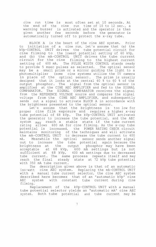
cine run time is most often set at 10 seconds. Atthe end of the cine run time of 10 to 12 sec., awarning buzzer is activated and the operator is thengiven another few seconds before the generator isautomatically turned off to protect the x-ray tube.
BLOCK A is the heart of the cine AEC system. Priorto initiation of a cine run, let's assume that (a) thekVp-CONTROL UNIT drives the tube potential circuit forcine filming to the lowest potential setting of 60 kVp,and (b) the mA-CONTROL UNIT drives the tube currentcircuit for the cine filming to the highest currentsetting of 600 mA. The PULSE WIDTH CONTROL stands readyto provide 5 msec pulses as selected. The optical sensormay be a small prism or a mirror guiding the light to aphotomultiplier (some cine systems utilize the TV camerain place of the optical sensor). The prism is usuallydesigned that it looks at the central 40 % to 60 % of theoutput phosphor. The signal from the optical sensor isamplified at the CINE AEC AMPLIFIER and fed to the SIGNALCOMPARATOR. The SIGNAL COMPARATOR receives the signalfrom the REFERENCE VOLTAGE source and compares the signalvoltage from the CINE AEC AMPLIFIER, and subsequentlysends out a signal to activate BLOCK A in accordance withthe brightness presented to the optical sensor.
Let's assume that the brightness is too low forproper cine film exposure and requires a higher x-raytube potential of 68 kVp. The kVp-CONTROL UNIT activatesthe generator to increase the tube potential, and the AECsystem may reach a stable state if the tube currentrating allows 600 mA for cine filming. As the x-ray tubepotential is increased, the POWER RATING CHECK circuitmaintains monitoring of the techniques and will activatethe mA-CONTROL UNIT to decrease the tube current to 400mA. Meanwhile the optical sensor sends another signalout to increase the tube potential again because thebrightness at the output phosphor may have beenacceptable at 68 kVp, 600 mA settings but is notsufficient at 68 kVp, 400 mA settings due to decreasedtube current. The same process repeats itself and mayreach the final steady state at 72 kVp tube potentialwith 350 mA tube current.
The description given above is that of an automaticiso-watt cine AEC system. Replacing the mA-CONTROL UNITwith a manual tube current selector, the cine AEC systemdescribed here becomes that of an "automatic kVp" cineAEC system with constant tube current during cinefilming.
Replacement of the kVp-CONTROL UNIT with a manualtube potential selector yields an “automatic mA" cine AECsystem. Both tube potential and tube current may be
7

manually selected and the exposure time (the pulse width)may be automatically varied. This type of cine AECsystem is very simple in its design concept, and iscalled "automatic pulse width" cine AEC system. If theelectronics are fast enough, this type of controlresembles a radiographic phototiming system, i.e., if oneconsiders the image intensifier and the optical sensortogether as the phototube, and each cine frame as thesingle radiographic exposure. For each of these types ofcine AEC systems, a minor change is required in Figure 2in accordance with its operational logic. For certainsophisticated AEC systems, additional features areprovided, such as (a) automatic optimum tube potentialsearch logic, (b) reduced x-ray tube loading duringautomatic search of the tube potential, etc.
III. RADIATION EXPOSURE
In a typical cardiac catheterization laboratory, thephysical factors which are of primary interest include,the cine film image quality and the radiation exposure tothe patient and the personnel conducting the examination.The radiation exposure values are affected by a number ofparameters such as the geometry employed, the radiationexposure required to expose the cine film, etc.
There is one equipment setting that affectsradiation levels as well as the image quality experiencedwith the cine imaging systems. This parameter is theimage intensifier input exposure sensitivity (IIIES).The IIIES, in turn, is determined by a number of factors:
(1) Cine Film Sensitivityprocessing dependent.
(film speed): can be
(2) The f-stop setting of the Cine Camera Lens.
(3) The Image Intensifier Conversion Factor, andQuantum Detection Efficiency (QDE); agingtendency is a slow (years) process.
(4) Light Transmission of the Optical Distributorand Lens System is affected by dirt collection.
In principle, the IIIES can be adjusted during theinitial calibration of the imaging chain to any valuewithin the equipment capabilities. However, the value ofIIIES which is selected should represents a reasonablecompromise between the quantum noise and the patientexposure.
During the initial calibration of the cine imaging

chain, the IIIES is obtained typically at 80 kVp tubepotential and adjusted to 10-20 µR/frame for 9" mode and20-30 µR/frame for 6" mode operation of the imageintensifier. It is also assumed that the developed cinefilm will be projected at a standard display rate of 24frames/sec 1&3 for normal viewing.
The IIIES level adjustment is attained through thecine AEC sensitivity control circuitry. Therefore, whenevaluating cine systems with respect to either patient orpersonnel exposure, it is highly desirable to determinethe IIIES at which the system is operating. A procedurefor making this determination is described in Section IVof this report.
A concept parallel to that of IIIES isfluoroscopic input exposure rate sensitivity (FIERs).
the The
FIERS is a s s o c i a t e d the fluoroscopic operation ofthe same cine imaging system, and the sensitivity isadjustable via the f-stop of the television camera lens,the television camera target voltage, and the automaticbrightness control (ABC) for fluoroscopy. Typically, theFIERS is set to 40-50 uR/sec (2.4-3.0 mR/min) for 9" modeand 80-100 uR/sec (4.8-6.0 mR/min) for 6" mode operationof the image intensifier4.
III-A. Patient Exposure
The total amount of radiation received by thepatient undergoing a cardiac catheterization examinationis accumulated from the fluoroscopic exposure during thecatheterization and the subsequent cine filming.
The radiation exposure arising from the fluoroscopicprocedure is proportional to the field size selected, andthe total fluoroscopic "ON" time and the averageradiation output at the entrance site. A simplifiedmethod to estimate the patient exposure, due to thefluoroscopy, can be calculated from the entrance skinexposure rate (typically, l-5 R/min) for an average sizepatient multiplied by the total fluoroscopic "ON" time(typically 10 minutes to 30 minutes). This simplifiedapproach assumes that the radiation beam is alwaysincident on the same site, and thus overestimates theactual dose to any one site, i.e., patient exposure perfluoroscopic/cine view (PA, LAO, RAO, LL, etc.)
The patient exposure due to the cine filmingexposures is largely dependent on the total number ofcine frames taken. The patient exposure due to the cinefilming is minimized by selecting the lowest filming ratewhich adequately images the dynamic aspects of theexamination. If the cine patient exposure/frame is known(typically 10-25 mR/frame)5 for each cine view, thecine patient exposure is simply proportional to the cine
9

patient exposure/frame (for that cine view) times thetotal number of cine frames taken for the correspondingcine view. Typically 300 frames to 1200 frames may betaken for one complete examination consisting of fewdifferent cine views.
The patient exposure of a given cine system may healtered and affected by (1) the filtration provided inthe primary beam path, and (2) the anti-scatter gridattached to the input surface of the image intensifierhousing. Therefore, in the evaluation and estimation ofpatient exposure, the radiation beam quality inHalf-value Thickness (HVT) and the anti-scatter gridemployed for the cine imaging chain should be considered.
III-B. Personnel Exposure
The radiation exposure to personnel conducting acine examination is produced by the radiation scatteredfrom the patient's body and by the leakage radiation fromthe x-ray tube. For a given situation the scatter to aspecific point is approximately proportional to theradiation entering patient and/or the imageintensifier tube. The actual relationship of the scatterexposure and the IIIES is determined by a number offactors including:
(1) Orientation of the x-ray beam, patient andpersonnel.
(2) Distance between the patient and the locationof the personnel.
(3) Radiation field size/collimation.
(4) Patient size.
(5) X-ray technique factors.
Since there are a large number of parameters whichaffect personnel exposure, a complete exposure evaluationrequires the measurement of exposure values at specificpersonnel locations during actual or simulated patientexamination conditions. The relative personnel exposureproduced by various cine systems can be indirectlycompared by measuring the IIIES, if so desired.
The stray radiation (scattered plus leakage) in thecardiac catheterization laboratory has been measured byvarious investigators6&7 and expressed byiso-exposure curves. Due to the high power loading ofcine fluorographic techniques, the iso-exposure curvesare often measured for the fluoroscopic case first.

Subsequently, these iso-exposure curves can beutilized with appropriate multiplication factors toaccount for the differences in the imaging techniquesbetween the cine fluorography and the fluoroscopy.Depicted in Figures 3 and 4 are typical iso-exposurecurves for the fluoroscopic operation of the cine imagingchain.
III-C. Summary
From the discussion of radiation exposures in acardiac catheterization laboratories above, the followingphysical parameters can be listed as the physical factorsthat should be included in a complete evaluation of acine imaging system:
(1) Image Intensifier Input Exposure Sensitivity(uR/frame).
(2) Fluoroscopic Input Exposure Rate Sensitivity(uR/sec.).
(3) The Beam Quality of Cine Operation in HVT's.
(4) Patient Exposure from Fluoroscopic Operation (R/min).
(5) Patient Exposure from Cine Filming (mR/frame).
(6) Personnel Exposure from Fluoroscopic Operation(mR/hr).
(7) Personnel Exposure from Cine Filming (mR/hr).
11

STRAY RADIATION LEVELS
Iso-exposure Curves in units of mR/hr.
Figure 3. Iso-exposure Curves Around A Cine ImagingSystem Equipped with A Cradle-top Examination Table.
Iso-exposure curves (mR/hr) with fluoroscopictechnique factors of: 96 kVp, and 1.5 mA, Field Size(entrance): 10 cm x l0 cm, and Tabletop ExposureRate: 1.95 R/min. (By permission of the AmericanHeart Association, & F.C. Rueter, Ref. #6.)
12

Figure 4. Iso-exposure Curves Around A Cine ImagingSystem Equipped with A U-arm Type Geometrical design.
Iso-exposure curves are obtained with fluoroscopictechnique factors of: 90 kVp, and 1.0 mA, Field Size(entrance): 8.5 cm x 11 cm, Tabletop Exposure Rate isnot Specified. (Courtesy of J.A. den Boer, and H. Mohrand MEDICAMUNDI. Adapted from Ref. # 7.)
13
IV. IMAGE INTENSIFIER INPUT EXPOSURE SENSITIVITYMEASUREMENT
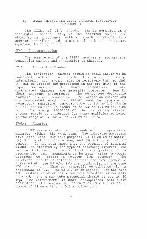
The IIIES of cine systems can be compared in ameaningful manner only if the measured values areobtained in accordance with a standard protocol. Thissection describes such a protocol and the necessaryequipment to carry it out.
IV-A. Instrumentation
The measurement of the IIIES requires an appropriateionization chamber and an absorber or phantom.
IV-A-l. Ionization Chamber
The ionization chamber should be small enough to becontained within the field of view of the imageintensifier, and should also be relatively thin so thatit can be located and positioned in the proximity of theinput surface of the image intensifier. Flat,disk-shaped chambers are generally preferred. Due totheir inherent inaccuracies, the pocket-type dosimetricchambers are not recommended. The ionization chamber andits associated electronic reader must be capable ofaccurately measuring exposure rates as low as l.0 mR/minor an accumulated exposure of as low as 1.0 mR per cinerun. The energy response of the ionization chambersystem should be calibrated for x-ray qualities at leastin the range of 1.5 mm Al to 7.0 mm Al HVT's.
IV-A-2. Absorber
IIIES measurements must be made with an appropriateabsorber within the x-ray beam. The following absorbershave been used for this purpose: (1) 15-20 cm of water,(2) 3.8 cm (1.5") of aluminum, and (3) 2.4 mm (3/32") ofcopper. It has been known that the accuracy of measuredvalues is affected by the type of absorbing material, dueto the differences in the resultant x-ray spectrum. It isrecommended that measurements be made using a copperabsorber to create a scatter free geometry. Thethickness should be selected so that the cine system isoperated at the 80 +/-5 kVp when controlled by the cineAEC circuitry. This can generally be achieved with athickness of 2.2 mm to 3.0 mm of copper. For the cineAEC systems in which the x-ray tube potential is manuallyselected, the x-ray tube potential should be set at 80kVp. The measurement is best accomplished with a kitconsisting of8 pieces of 23 cm x 23 cm x 0.5 mm and 8pieces of 23 cm x 23 cm x 0.2 mm of copper.
14

The purity of the copper sheets employed as theabsorber for simulation of the cine fluorographicexamination should be better than 99.9% pure copper, suchas type 110 copper sheets.
IV-R. Measurement Procedure
In order to insure reproducible results, theprocedure described below and the geometry depicted inFigure 5 should be adhered to.
IV-R-l. Anti-Scatter Grid
In Figure 5, notice that the anti-scatter grid isremoved from the image intensifier and the ionizationchamber is positioned AS CLOSE AS POSSIBLE but not onthe image intensifier input phosphor surface.
*********************CAUTION*************************
For image intensifier systems in which theanti-scatter grid is not readily removable,extreme care must be exercised. The imageintensifier tube is an implosion hazard, and anexpensive device to replace.
***************************************************
In the event that it is not practical to remove theanti-scatter grid, the ionization chamber can be placedin front of the anti-scatter grid but the measured valuesmust be corrected for attenuation due to the anti-scattergrid. The correction factor varies with the type ofanti-scatter grid employed, and is normally availablefrom the grid manufacturer. It should be pointed out thatthe anti-scatter grid is fragile and should be handledwith care.
IV-D-P. Focal Spot Image Intensifier Tube Distance
If the distance between the focal spot and the imageintensifier (FID) is variable it should be adjusted to 76cm (30 inches) or as close to 76 cm as possible forsystems in which the x-ray tube is installed under thecradletop. For the cine systems equipped with a C-arm ora U-arm, the FIT! varies depending on the particulardesign of the cine system and the adjustable range of theFIT! is also greater. The FID should be set to 100 cm(40") for these systems.
If the FIDs suggested above cannot be appropriatelyobtained, the FID employed should then be recorded.
15

Ionization Chamber: Flatdisk-shapedCopper Phantom Thickness: 2.4 mmField Size @ Image Intensifier:
10 cm x l0 cm for 15 cm Mode18 cm x 18 cm for 23 cm Mode
X-ray Tube Potential: 80 +/- 5 kVpAnti-scatter Grid: Removed
Figure 5. Schematic Illustration of MeasurementArrangement for Image Intensifier Input ExposureSensitivity.
The copper phantom should be located at the x-raytube collimator when accessible, or alternativelyat the tabletop as illustrated.
IV-B-3 Field Size
Adjust the radiation field size (via automaticcollimation system, or manually) to the size of theactive image intensifier input phosphor. The actualradiation size should be measured and recorded along withthe measurement data. Typically the radiation field canbe set to 10 cm x l0 cm for the 15 cm (6") input phosphorand 18 cm x 18 cm for the 23 cm (9") input phosphor.
IV-B-4. X-ray Tube Potential
Because the sensitivity (conversion factor) of imageintensifier tubes is photon-energy dependent it isdesirable to make measurements at 80 +/- 5 kVp.
16

If the tube potential can be selected manually, setit to 80 kVp, place 2.4 mm of copper in the beam andproceed with the measurement. If the x-ray tubepotential cannot be selected manually, proceed asfollows: place a 2.4 mm copper phantom in the beam andobserve the x-ray tube potential which is being selectedby the cine AEC. If the x-ray tube potential is notwithin the 75-85 kVp range adjust the preset orpre-determined x-ray technique factors such as the x-raytube current, and/or pulse width to bring the x-ray tubepotential into range. If the x-ray tube potential cannotbe brought into range change the attenuator thicknessuntil the x-ray tube potential falls within theacceptable range. Thicknesses of the copper filters inthe range of 2.0 mm to 3.6 mm are acceptable.
IV-B-5. Measurement
It is generally desirable to operate the ionizationchamber in the rate mode. The x-ray exposure must be longenough to permit the x-ray system and exposure meter toreach a stable value and should be terminated as soon asa stable reading is obtained in order to reduce x-raytube heat loading. Normal precautions should be exercisedon repeat runs to prevent overloading the x-ray tube andhousing.
A safety interlock mechanism is normally providedwith the cine camera so that the cine exposures cannot bemade with an empty film magazine. This interlock shouldbe bypassed to avoid wasting cine film.
IV-B-G. Correction Factors
A. distance correction factor should be applied ifthe ionization chamber is not located precisely at theimage intensifier housing surface.
V. FLUOROSCOPIC INPUT EXPOSURE RATE SENSITIVITYMEASUREMENT
The FIERS can be measured with the same arrangementand instrumentation described for the IIIES measurementand depicted in Figure 5. With the system operated in thefluoroscopic mode, the measurement geometry, the copperphantom, etc. may remain exactly the same as that ofIIIES measurement. The fluoroscopic mode of the cineimaging system is activated by stepping on thefluoroscopic pedal rather than the cine filming pedal.
17

VI. HALF-VALUE THICKNESS MEASUREMENT
Utilizing the IIIES measurements arrangementdescribed in section IV, one can simply place appropriatethicknesses of aluminum filters to carry out the HVTmeasurement in accordance with the good geometryconditions 8. The ionization chamber is, of course,now positioned in front of the copper phantom in the cineimaging system for the measurement of HVT. The ionizationchamber and its associated electronic reader should becapable of accurately measuring exposure rates as high as10 R/min or an accumulated exposure as high as 10 R permeasurement. There should be a distance of approximately10 cm between the ionization chamber and the copperphantom to reduce the back scatter from the phantom. Acopper phantom of 2.4 mm is placed at the imageintensifier as specified previously. However, it is notnecessary to remove the anti-scatter grid.
When the fluoroscopic automatic brightnessstabilization (ABS) circuitry of the cine imaging systemcannot be overriden, a modified approach is necessary inorder to maintain the x-ray tube potential as thealuminum filter is introduced into the primary beam. Thiscan be accomplished by replacing 0.4-0.6 mm of the copperfilters with approximately 5.0 mm of aluminum.
The aluminum filters should be the same size as thatof copper. Proceed to initiate a fluoroscopic exposure,and compare the fluoroscopic technique factors with thatof the IIIES measurement. Reduce or increase the aluminumfilter thickness until the desired x-ray tube potentialor 80 kVp is obtained. Once this is accomplished the HVTmeasurement can be carried cut employing the followingprocedure.
(1) Record the radiation exposure rate, thegeometry and the combined aluminum/copper phantom(including the total thickness of each absorber).
(2) Take one 1.0 mm aluminum filter from thecombined aluminum/copper phantom, and insert thealuminum filter between the x-ray tube and theionization chamber. The aluminum filter can beconveniently attached to the collimator face withadhesive tape.
(3) Record the radiation exposure rate as I.0 mmaluminum attenuation data. The fluoroscopic techniquefactors should remain the same, since the totalattenuation of the radiation to the image intensifieris not significantly altered by the re-location ofthe aluminum filter.
18

(4) Repeat the above steps until sufficient dataare obtained to determine the HVT.
VII. ESTIMATION OF PATIENT AND PERSONNEL EXPOSURES
The radiation exposures (or exposure rates)receivable by the patient and the personnel can bemeasured by actual monitoring utilizing film badges (notpractical for patients) or thermoluminescent dosimeter(TLD) chips taped onto the patient, the physicians, andother personnel. Exposure measurements utilizing TLDchips, for instance, can then be conducted while thecatheterization procedure is in progress6,7.However, in general, radiation exposure levels aresought afterwards and can only be estimated.
When necessary, an approximate estimate of patientexposure can be obtained from the IIIES and the FIERS byassuming that the patient attenuates the primary beam bya kVp-dependent factor of approximately l/200 to l/1000.Corrections must then be applied to take into account thedifference in distances, the number of cine frames, andthe fluoroscopy time.
The personnel exposure can be estimated by theapplication of similar assumptions, viz: the scatteredradiation exposure at 1 m from the patient is modified bythe angular dependent factor and therefore isapproximately l/200 to l/l000 of the patientexposure 9. The accuracy of such an approach is onlyacceptable to obtain a rough estimate in the absence ofaccurate data.
A more practical and accurate estimate can beachieved by conducting radiation exposure measurementsunder a typical catheterization condition. A suggestedmethod for accomplishing this task is described below.
VII-A. Instrumentation
The instrumentation required for the measurement ofpatient exposure is similar to that required for theIIIES measurement. Some differences exist, however, theyare: (1) the ionization chamber and its associatedelectronic reader must now be capable of accuratelymeasuring exposure rates as high as 600 R/min or anaccumulated exposure as high as 150 R per cine run, (2)the anti-scatter grid is installed (not removed), and (3)the copper absorber is replaced by a water phantom orplastic phantom. For personnel exposure measurements, asurvey meter type ionization chamber with 100 cm 2
or greater active area is required. Its energy responseand calibration should be similar to the ionization

chamber employed for IIIES measurement. The sensitivityof the survey meter should be capable of measuringexposure rates ranging from 0.1 mR/hr to 10 R/hr.
VII-B. Preparation
In order to simulate theconditions, a number of physireproduced. They are:
(1) Image Intensifier Mode, i.e. 1(9") mode.
clinical examinationcal factors must be
5 cm (6") or 23 cm
(2) X-ray tube potential for an average patient.
(3) X-ray tube current, pulse width.
(4) The focal spot size.
(5) Cine filming rate employed.
(6) Geometry of the examination.
(7) Location of personnel in the room.
VII-C. Phantom
Unlike the absorber (or, phantom) employed in theIIIES protocol, the phantom utilized in the patient andpersonnel radiation exposure measurements must yield aradiation pattern similar to the actual clinicalsituation. Therefore, the phantom should be made ofwater, plastic (i.e., Plexiglas), or other tissueapproximating material.
A phantom consisted of several pieces of plasticplates 35 cm x 35 cm x 2.54 cm (14" x 14" x 1") issuitable. A total of 20 cm (8") thickness closelysimulates an average size patient.
VII-D. Measurement Procedure
The cine fluorographic imaging chain is set upsimilar to that of a typical catheterization examination.The scattering phantom (20 cm thick, or 8") is placed andpositioned on the examination table in the middle of theprimary beam. The ionization chamber for patient exposuremeasurement is positioned on the x-ray tube side of thephantom.
For personnel exposure measurement, one can positionthe survey meter type ionization chamber at the locationwhere the operator stands, or other desired locations. At
20

each location where the radiation exposure measurement isdesired, a minimum of five measurements should beconducted, namely, at five distances from the floor: (a)eye/thyroid level, (b) chest level, (c) abdominal / gonadslevel, (d) knee level, and (e) ankle level.
The contributions to the different radiationexposures from fluoroscopy and the cine fluorography aremeasured with the ionization chamber underneath thephantom and with the survey meter positioned at thedifferent personnel locations. The same measurementarrangement is employed for the fluoroscopy and cinefluorography. The exposure time for both measurementsmust be sufficiently long to allow for the ionizationchamber/electrometer system to stabilize (approximately 4sec.).
VIII. MEASUREMENT EXAMPLES
In accordance with the description and protocols, aset of sample measurements is presented. The technicaland physical factors are listed in Tables II, and III[Table II for cine fluorography and Table III forfluoroscopy], and the measurement results in Tables IV,V, and VI. The cine imaging equipment employed for thesemeasurements had a U-arm type configuration similar tothe equipment used in Figure 4, and was calibrated andoptimized by the field service engineers a few days priorto the measurements. The image quality of clinicalstudies for fluoroscopy and cine fluorography wasacceptable to the cardiologists. The results of thisparticular cine fluoroscopic imaging system for IIIES,FIERS, and HVT are listed in Table IV. The acceptablerange of each parameter is also listed in Table IV forcomparison10,11. It is noteworthy to point out thatthe input phosphor material of the image intensifier wasCsI and had A high quantum detection efficiency (QDE).
21


Note : Actual patient exposure can beestimated using these values, the totalfluoroscopic "ON" time, and the totalnumber of cine frames.
Personnel exposure measurements conducted forvarious cine systems have shown a real possibility ofdelivering excessive amounts of radiation to thephysicians and other personnel in the cardiaccatheterization laboratories 12'13'&14. Table VIshows an example of the benefit of using lead protectivedevices during catheterization procedures. The locationsA, B, and C correspond to that of a physician, his/herassistant, and a nurse, respectively. Their relativegeometrical relationship with respect to the cine imagingsystem and the examination table is depicted in Figure 6.
23

Table VI. PERSONNEL EXPOSURE RATES
* No special lead protective devices were installedon the examination table.
** With lead protective devices (0.25 mm Pb Equ.)specially designed for this particular cine system.
"M" minimal or not measurable.
24
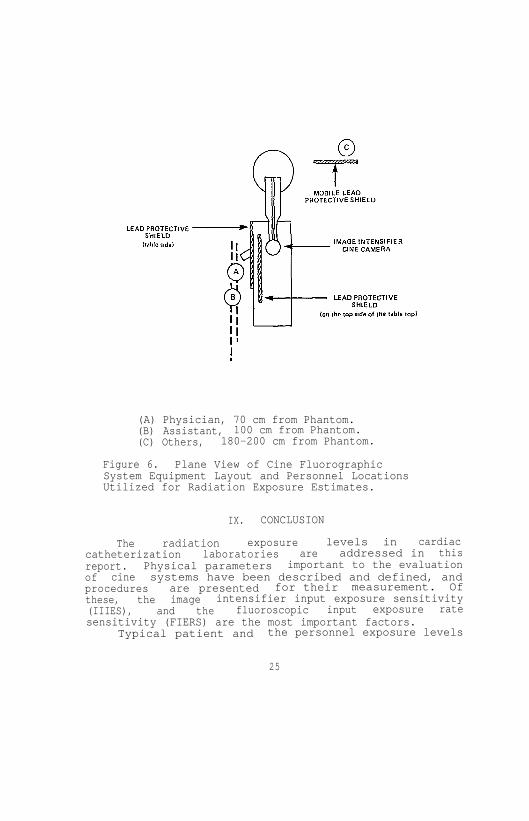
(A) Physician, 70 cm from Phantom.(B) Assistant, 100 cm from Phantom.(C) Others, 180-200 cm from Phantom.
Figure 6. Plane View of Cine FluorographicSystem Equipment Layout and Personnel LocationsUtilized for Radiation Exposure Estimates.
IX. CONCLUSION
The radiation exposure levels in cardiaccatheterization laboratories are addressed in thisreport. Physical parameters important to the evaluationof cine systems have been described and defined, andprocedures are presented for their measurement. Ofthese, the image intensifier input exposure sensitivity(IIIES), and the fluoroscopic input exposure ratesensitivity (FIERS) are the most important factors.
Typical patient and the personnel exposure levels
25

are presented for reference and comparison purposes. Therelationships between IIIES, FIERS, patient exposure andpersonnel exposure are system dependent and physicistsshould measure these relationships as necessary. It isthe intent of the task force that this report offer someguidance, and be utilized by practicing radiologicalphysicists to assist in the evaluation of a cardiaccatheterization laboratory when the need arises.
The procedure described can be modified to accountfor various equipment configurations and operations underdifferent clinical arrangements such as (1) single planeangled view using a cradletop, (2) bi-plane cine systems,and (3) lateral cine fluorography utilizing either asingle plane or a bi-plane system.
26
REFERENCES
(1) Report of Inter-Society Commission for Heart DiseaseResources, "Optimal Resources for Examination ofthe Chest and Cardiovascular System," Circulation,53 : Al-A37, (1976).
(2) Cameras for Image Intensifier Fluorography, ICRUReport No. 15, International Commission onRadiation Units and Measurements, (1969).
(3) P.P. Lin, "Acceptance Testing of Cine ImagingSystems for Cardiac Catheterization Laboratories,"in AAPM Proceedings Series No. 1, AcceptanceTesting of Radiological Imaging Equipment, pages:227-240, (1982). Published for AAPM by theAmerican Institute of Physics, New York, New York10017.
(4) P.P. Lin, "Acceptance Testing of Image IntensifierChain," in AAPM Proceedings Series No. 1, AcceptanceTesting of Radiological Imaging Equipment, pages:241-248, (1982). Published for the AAPM by theAmerican Institute of Physics, New York, New York10017.
(5) J.H. Gough, R. Davis, and A.J. Stacey, "RadiationDoses Delivered to the Skin, Bone Marrow and Gonadsof Patients During Cardiac Catheterization andAngiography," British Journal of Radiology, 41 :508-518, (1968).
(6) F.G. Rueter, "Physician and Patient Exposure DuringCardiac Catheterization,' Circulation, 58 :134-139,(1978).
(7) J.A. den Boer, and H. Mohr, "Distribution ofScattered Radiation Around the Cardio Diagnost,"Medicamundi, 21 :121-126, (1976).
(8) Physical Aspects of Irradiation, Recommendations ofInternational Commission on Radiological Units andMeasurements Report l0b, National Bureau ofStandards Handbook 85, (1964).
(9) Structural Shielding Design and Evaluation forMedical Use of X-rays and Gamma Rays of EnergiesUp to 10 MeV, NCRP Report No. 49, September 1976.National Council on Radiation Protection andMeasurements, 7910 Woodmont Ave., Washington, D.C.20014.
27

(10) R.J. Moore, "SCA Cine Testing Results:1981",presented et the Annual Meeting of the Societyfor Cardiac Angiography, San Francisco, CaliforniaMay, 1982.
(11) M.P. Judkins, "Angiographic Equipment: The CardiacCatheterization Angiographic Laboratory," inCoronary Arteriography, A Practical Approach,H.L. Abrams, Editor, Little Brown and Company,Boston, 1982.
(12) G.J. Wold, R.V. Roheele, and S.F. Agarwal,"Evaluation of Physician Exposure During CardiacCatheterization," Radiology, 99 :188-190, (1971).
(13) S.J. Malsky, B. Roswit, C.B. Reid, and J. Heft,"Radiation Exposure to Personnel During CardiacCatheterization," Radiology, 100 :671-674, (1971).
(14) S. Balter, F.M. Sones, and R. Brancato, "RadiationExposure to the Operator Performinn CardiacAngiography with U-arm Systems," Circulation,58 : 925-932, (1978).
28