evaluation of stability of the rock slopes in taiz city and …€¦ · · 2017-09-18lithological...
TRANSCRIPT

Abdul-Aleam A. A. D. Al-Qadhi.Int. Journal of Engineering Research and Application www.ijera.com
ISSN : 2248-9622, Vol. 7, Issue 9, ( Part -4) September 2017, pp.36-54
www.ijera.com DOI: 10.9790/9622-0709043654 36 | P a g e
Evaluation of Stability of the Rock Slopes in Taiz City and
Surrounding Areas of Yemen Using Slope Mass Rating (SMR)
System and Kinematic Analysis Technique
Abdul-Aleam A. A. D. Al-Qadhi*, M.R. Janardhana** *, ** (Department of Geology, Yuvaraja’s College, University of Mysore, Mysuru, India
*Email: [email protected], ** Email: [email protected])
ABSTRACT Assessment of stability of rock slopes is important to thwart the occurrence of landslides and consequent socio-
economic evils. The present maiden study is carried out in and around Taiz city known for geotechnical hazards
by isolating 14 of 110 field stations located along road cuts, quarries and natural exposures representing varying
lithological and geotechnical conditions. The stability of rock slopes was evaluated by applying the original
Slope Mass Rating (SMR) system. The parameters of SMR system were measured based on field and laboratory
investigations. The failure mode at each site and its potential failure directions were determined kinematically
using the stereographical projection method employing Stereonet software. The obtained results from applying
SMR system at 14 rock slope stations demonstrated that there are various modes of failure and a single slope
may have been affected by more than one type of failure depending on the relationship between the
discontinuities and slope face, discontinuity characteristics and lithological conditions. The calculated values of
SMR show variations from 1.4 to 70.4 indicating that these values plot from "Very Bad" (Vb) class to "Good"
class (IIb). The results also indicate the more scope for planner, toppling and/or big wedge failures and warrants
suitable corrective measures, especially in the areas where the SMR values fall in IV and V classes. Further,
slope Nos. 5 (zone-I) and 40 (zone-I) are "Stable" against wedge and toppling failures respectively and five slope
locations (22, 36, 68, 76 and 86) are "Partially Stable" against toppling failures, while two rock slope locations
(Nos. 77, 92 and 96) are "Unstable" against the various failures. The unstable slope locations vulnerable for
planar/falling failure are 5, 30, 57, 76 and 86. The remedial measures to control slope failures in 14 slope
locations are suggested based on SMR values.
Keywords: Kinematic Analysis, Slope Mass Rating, Slope Stability, Taiz City in Yemen ---------------------------------------------------------------------------------------------------------------------------------------
Date of Submission: 31-08-2017 Date of acceptance: 13-09-2017
---------------------------------------------------------------------------------------------------------------------------------------
I. INTRODUCTION Taiz area in Yemen is located adjacent to
tectonically active rift zone known as Red Sea–Gulf
of Aden rift system. This active zone can cause the
reactivation of the old fault systems and may create
new faulting lines and discontinuities (joints) in the
Tertiary rock masses of area. The slopes in Taiz area
developed over Tertiary rocks are well known for
their instability due to the dynamic nature of slopes,
lithology, anthropogenic activities, rainfall and ong-
oing neo-tectonic activities. Urbanization followed
by unplanned rapid development of buildings and
other infrastructure facilities have caused unfav-
ourable changes in the configuration of Tertiary rock
slopes causing landslides and also instability in the
form of the development of cracks in the walls,
foundation problems leading to collapse of the
buildings (Fig.1), thus bringing undesirable socio-
economic changes in the lives of the citizens. There
are many landslides/collapses that occurred at differ-
rent places in the study area. In 2010, unplanned
excavation and vibrations caused by blasting at the
foot slope of Amid Mountain, near Taiz University
for the purpose of construction has enhanced the
vulnerability of slopes to landslide. In order to pro-
vide safety both to the common man and the civil
structures as well as to reduce the slope failures,
slope characterization and evaluation of stability of
the road cut slopes are required. The analysis of
slope characterization depends upon many param-
eters and database related to slope, rock/rock mass,
meteorology, etc. [1a, 1b, 2]. The stability of rock
slopes is essentially governed by the joint sets,
characteristics of joint materials, seepage pressure,
and depth and steepness of the excavated slope face
and its orientation with respect to the joint sets [3].
RESEARCH ARTICLE OPEN ACCESS

Abdul-Aleam A. A. D. Al-Qadhi.Int. Journal of Engineering Research and Application www.ijera.com
ISSN : 2248-9622, Vol. 7, Issue 9, ( Part -4) September 2017, pp.36-54
www.ijera.com DOI: 10.9790/9622-0709043654 37 | P a g e
Slope mass characterization is necessary for
geotechnical studies and it involves laboratory and
field investigations of intact rock blocks and
discontinuities or defects (e.g., joints, weak bedding
planes, weak zones, planes, faults, etc) present in
rock mass. The geomechanical behaviour of rock
mass in situ is governed by characteristics of intact
rock and discontinuities on the one hand and their
occurrence in the environment with many natural
complexities on the other.
Fig.1 Photographs showing dilapidated conditions of buildings underlain by Tertiary volcaniclastics in the
study area [4]
Due to complexity of rock mass with
varying physico-mechanical in situ properties, num-
erous classification systems have been developed for
the characterization, classification as well as to gain
the knowledge on the rock mass properties and also
to provide a quantitative valuation of rock mass by a
simple arithmetic algorithm [5]. Most of these classi-
fication systems were originally applied in tunnels
and underground mining (e.g. Q, RMR and MRMR
systems). Some classification systems, originally
developed for underground excavations have been
used directly (e.g., Q and RMR system) or have been
modified (e.g., the RMS, SMR, SRMR and CSMR
systems comprise modifications of the RMR system)
for the assessment of the stability of the slopes [6].
Among the classification systems which come with
relevant recommendations for the remedial meas-
ures, the SMR [7] technique derived from basic
RMR [8,9] is widely used to identify the potentially
hazardous rock cut slopes.
In the present work, slope stability studies
were conducted at 14 rock slope stations applying
rock mass rating (RMR) and original slope mass
rating (SMR) systems. Kinematic analysis was also
carried out for the identification of mode of failure
and its directions in these sites, in addition to the
evaluation of the geotechnical properties of rock/
rock mass.
II. STUDY AREA Taiz city is located on the south-western
part of Yemen in the watershed area of upper Wadi
Rasyan covering foothill and slope regions of Sabir
Mountain and the area is bound by the latitudes; 13°
31' 49" and 13° 44' 29" N, and longitudes; 43° 54'
17" and 44° 09' 04" E (Fig. 2). Topographically, the
study area is well represented by mountains, isolated
hills, steep slopes, undulating eroded lands with
major wadis, and plains and loess covered plateau
(Al-Janad Plateau) with elevations ranging from
about 800 m to 3000 m above mean sea level.
According to the Meteorological data, the annual
rainfall in the investigated area is bimodal; the first
season starting from April to June with peak in May
and the second is from August and October with
peak in September.
The average annual rainfall in the study area is
approximately 520 mm [10]. Climate data shows
that the average monthly temperature in the study
area is low during dry period from October to March

Abdul-Aleam A. A. D. Al-Qadhi.Int. Journal of Engineering Research and Application www.ijera.com
ISSN : 2248-9622, Vol. 7, Issue 9, ( Part -4) September 2017, pp.36-54
www.ijera.com DOI: 10.9790/9622-0709043654 38 | P a g e
while it goes up during the rainy season. Low
temperatures are recorded during the dry months
from mid-October to mid-March, with mean maxi-
mum temperatures in the range of 25.57° to 29.63
°C. High temperatures are recorded during the wet
months from mid-March to mid-October, with mean
maximum temperatures varying from 30.47° to
32.60 °C [10].
Fig.2 Location map of the study area
The rock masses of the Taiz area belong to
Tertiary bimodal volcanic materials and their assoc-
iated intrusive bodies (i.e., Sabir granite). The Tert-
iary bimodal volcanic materials are represented by
alternating sequences of volcanic lava flows and
volcaniclastic deposits of variable composition rang-
ing from mafic to the silicic types. The sequence of
volcanic lava flows and volcaniclastic deposits are
the product of Red Sea – Gulf of Aden rift tectonics
that was erupted in five phases [11, 12a, 13] and in a
repeated manner. The flow sequences from bottom
to top comprise (Fig. 3):
1) Tertiary lower mafic flow (Tb1, Eocene)
2) Tertiary lower silicic sequence phase (Tr1, Eo-
cene -Oligocene)
3) Tertiary middle mafic sequence phase (Tb2,
Oligocene-Miocene)
4) Tertiary upper silicic sequence phase (Tr2,
Oligocene-Miocene)
Tb1 is represented by dark grey to chocolate
brown (in fresh surface) or dark reddish brown (on
outer weathered/altered surface) coloured jointed/
massive basaltic lava flows with basaltic volcanic-
lastic materials. Often the jointed basaltic lava flows
are interbedded /alternated with basaltic volcanic-
lastic materials. These rocks are marked by different
types of discontinuities as evidenced by the develop-
pment of irregular joints, columnar joints, (thermal
origin) in addition to other discontinuities in them.
The rock blocks formed by these joints occur in
various sizes and shapes such as columnar, poly-
hedral, tabular, prismatic and rhombohedral blocks.
Tr1 forms rhyolitic/ ignimbritic plateaus
and rarely small hills in the study area. Petrolo-
gically, Tr1 is represented by jointed rhyolites /
dacites, ignimbrites, rhyolitic tuffs, lapillistones,
volcaniclastic breccias, and random pumice and
obsidian [14]. Higher amounts of volcaniclastic
rocks in Tr1 sequence indicate that initially volcan-
ism was more explosive [13]. Vertically, this seque-
nce shows change in lithology and colonnade colum-
nar jointing features.
Tb2 is represented by basaltic lava flows
and volcaniclastic deposits extruded primarily thro-
ugh the feeders like - dykes. Volcaniclastic deposits
of this phase are classified into tuff-breccias, lapilli-
tuffs, agglomerates and lapillistones based on their
particles sizes [14]. In the study area, the rocks and
deposits of Tb2 have a greatest areal extent in comp-
arison to all other units with thickness reaching up to
100 m and covering 39.61 % of the total area. These
lava flows show different physical characteristics
(colour, heterogeneity, discontinuity, thickness, hori-
zontal attitude, weathering/alteration, intercalation

Abdul-Aleam A. A. D. Al-Qadhi.Int. Journal of Engineering Research and Application www.ijera.com
ISSN : 2248-9622, Vol. 7, Issue 9, ( Part -4) September 2017, pp.36-54
www.ijera.com DOI: 10.9790/9622-0709043654 39 | P a g e
and repetition with depth) both in vertical and
horizontal directions implying variation in eruption
type, mode of transport, distance travelled from the
vent, temperature of the deposits, particle size, water
content and paleorelief of older Tr1 sequence [14].
Fig. 3 Geological map of the study area (modified after [15, 12b, 13, 14]) with locations of the investigated
stations

Abdul-Aleam A. A. D. Al-Qadhi.Int. Journal of Engineering Research and Application www.ijera.com
ISSN : 2248-9622, Vol. 7, Issue 9, ( Part -4) September 2017, pp.36-54
www.ijera.com DOI: 10.9790/9622-0709043654 40 | P a g e
The outcrops of Tr2 sequence are limited
and restricted into the vicinities of the Taiz city
along the E-W Sabir fault system. The rocks cons-
titute isolated domal mountains and plugs of differ-
ent sizes and shapes. It covers an area of 41.47
sq.km (10.6%) of the total area. Tr2 is represented
by fine-grained, porphyritic, yellow to gray, white,
red, green and pink coloured jointed /massive rhyo-
lites / dacites and/or varicolored volcaniclastics of
rhyolitic composition. Volcanic pitchstone is also
observed in different locations as lava flows or as
irregular bodies intercalated with volcaniclastic
materials. Volcaniclastic materials of the study area
are classified based on their particle sizes into ignim-
brites, rhyolitic tuffs, rhyolitic lapilli-tuffs and
rhyolitic lapillistones [14]. The most characteristic
feature of Tr2 is its occurrence as alternating seq-
uence of more than one lava flow with variations in
physical properties both in horizontal and vertical
directions even in the same location.
Tertiary Sabir granitic pluton (Tg) is emplaced
as laccolithic body inside the older stratified Tertiary
Yemen volcanic rocks, forming the dominant mor-
phological feature i.e., Sabir Mountain over- looking
the city of Taiz in the southern part of the study area
(Fig. 3). It is characterized by high lands, steep
slopes and deep valleys. Physical weathering of
varying intensities has produced different sizes of
granitic blocks and boulders along the slopes. It
consists mainly of massive, white to greyish white
coloured, medium to coarse-grained grading up to
granite porphyry with almost < 5 % of dark minerals
alkaline or peralkaline granite. The rocks belong to
the alkaline or peralkaline suite of A-type granites
[16]. These are produced by fractional crystallization
in the basic magmas [17, 18]. For the assessment of
the stability of the slopes in and around Taiz city
(Table 1), fourteen slope locations representing
various rock types with heterogeneous geotechnical
properties were chosen.
III. METHODOLOGY 1.III Field Investigations
Reconnaissance survey carried out throu-
ghout the Taiz area facilitated the selection of 110
locations along road cuts and on the natural rock
outcrops. Detailed field and laboratory studies at 110
locations restricted the present slope stability asse-
ssment to 14 rock slope stations representing diverse
lithological and geotechnical conditions. On these
exposures, the field scanline survey technique [19a,
b] was applied in three dimensions (as far as poss-
ible) to obtain the structural data related to Rock
Mass Rating (RMR) system such as discontinuities
(joints) characteristics and their conditions as well as
the attitude of slopes (dip [βs] and dip direction
[αs]).
Table 1 Locations and lithologies of the investigated
slopes
For each discontinuity (joint) intersecting the
scanline the following characteristics/ measurements
are recorded: orientation or attitude of discontinuity
([βj] / [αj]) with respect to slope, spacing, persis-
tence (m), aperture (mm), roughness, state and thick-
ness of filling material, water flow and wall weath-
ering. Procedures recommended by ISRM (1981a)
(Table 2) were followed to measure and record the
field data. The discontinuity orientations data ([βj] /
[αj]) obtained in the field were plotted stereograph-
ically (equal-area stereographic projection) using
computer software, called Rock Works /14 [20] and
the joint sets were distinguished for all scanline
surveyed data and then the pole concentrations were
contoured. The maximum density points or mean
density on the contour diagram were selected as the
best representation of the average orientation of each
discontinuity set (Table 2). The orientations of main
discontinuity (joint) sets ([βj] / [αj]) and orientation
of each slope ([βs]/ [αs]) were used in the calculation
of SMR (Table 3) and the same were used to
perform kinematic analysis to identify the mode of
potential failure. The identification of the (i) mode
of failure was done by re-plotting βj and αj of the
recognized main joint sets of each rock slope station
on the stereo-net using RockWorks/14 software [20]
and (ii) potential unstable zones in the slopes emp-
loying stereo-net software, version 9.2.1 [21] (Fig.
4).
The internal friction angle (Ø°) of each rock
mass used for kinematic analysis has been estimated
based on the RMR values. Kinematic analysis is
based on the Mark-land Test Plot method as
described by [22, 23] and later modified by [24].
This method was used to assess the potential mecha-
nism i.e., toppling, planar, or wedge sliding along
the identified discontinuities (joints). Accordingly, a
planar failure is possible when the dip direction of
the sliding plane is within ± 20° of the dip direction
of the slope face and angle of sliding plane is less
than the slope angle but greater than the friction
angle along that plane. A wedge failure may occur

Abdul-Aleam A. A. D. Al-Qadhi.Int. Journal of Engineering Research and Application www.ijera.com
ISSN : 2248-9622, Vol. 7, Issue 9, ( Part -4) September 2017, pp.36-54
www.ijera.com DOI: 10.9790/9622-0709043654 41 | P a g e
Table 2 Orientation (dip/dip dir) of the main discontinuity (joint) sets obtained stereographically, their
average/minimum spacings their average characteristics and ratings used in the calculation of the basic RMR
rating for investigated slope rock masses in and around Taiz city, Yemen
Table 2 continued
Where m: meter, mm: millimeter, (…): the values in parentheses represent the mean discontinuity set spacings, Min:
minimum, *: contact between two zones, C.dry: completely dry, S: slightly, Sr: slightly rough, Sf.: Soft, Hd.: hard, Sm.:
smooth, Md: moderately/medium, V.: very, [ ]: rating of a parameter according to Beniawski [9], Rr: roughness rating.
Abdul-Aleam A. A. D. Al-Qadhi.Int. Journal of Engineering Research and Application www.ijera.com
ISSN : 2248-9622, Vol. 7, Issue 9, ( Part -4) September 2017, pp.36-54
www.ijera.com DOI: 10.9790/9622-0709043654 42 | P a g e
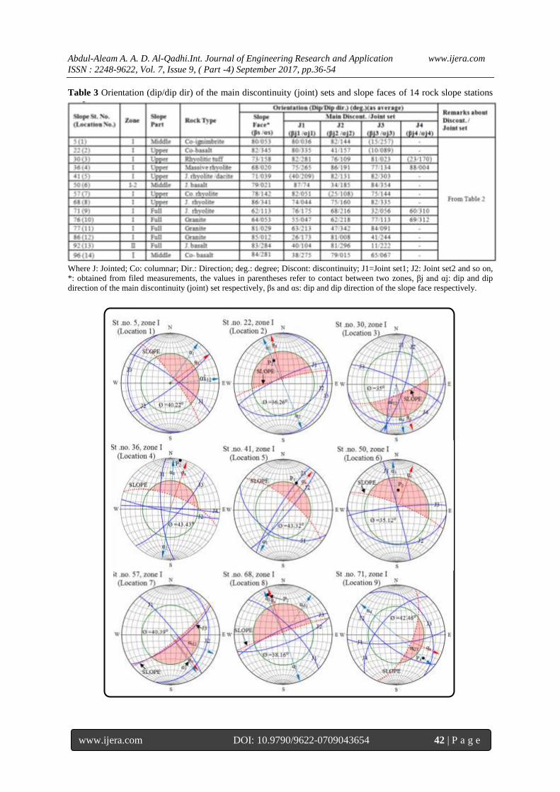
Table 3 Orientation (dip/dip dir) of the main discontinuity (joint) sets and slope faces of 14 rock slope stations
Where J: Jointed; Co: columnar; Dir.: Direction; deg.: degree; Discont: discontinuity; J1=Joint set1; J2: Joint set2 and so on,
*: obtained from filed measurements, the values in parentheses refer to contact between two zones, βj and αj: dip and dip
direction of the main discontinuity (joint) set respectively, βs and αs: dip and dip direction of the slope face respectively.

Abdul-Aleam A. A. D. Al-Qadhi.Int. Journal of Engineering Research and Application www.ijera.com
ISSN : 2248-9622, Vol. 7, Issue 9, ( Part -4) September 2017, pp.36-54
www.ijera.com DOI: 10.9790/9622-0709043654 43 | P a g e
Fig.4 Plot of main joints and slope faces for fourteen rock slope locations. The pink coloured area indicates the
critical zone of failure. The symbols used in the figure are: J1=Joint set1, J2= Joint set2,…and J4= Joint set4;
αs: dip direction of slope face, α1,2,…4: dip direction of J1, J2,….J4; βi, αi are plunge and trend of line of
intersection of two joints respectively; βi12, αi12 are plunge and trend of line of intersection of two joints J1
(joint set1) and J2 (joint set2) respectively so on; Ø: friction angle of the rock mass in degree, P1…4 : pole of
the plane 1, 2…4.
when the trend (dip direction) of the line of inters-
ection (αi) is within ± 20° of the dip direction of the
slope face, the plunge (dip angle) of the line of
intersection (βi) is less than the dip angle of the
slope face (βs) (daylights on slope) but greater than
the angle of friction of the failure plane (Øj). The
kinematic feasibility criterion for toppling failures
was formulated as detailed [25]: [(90° − βs) + Øj <
βj], where βs is the dip angle of the slope face, Øj is
the friction angle of the joint plane and βj is the dip
angle of the joint plane.
Based on the average spacing of each main
discontinuity (joint) set, the volumetric joint count
(Jv) defined as sum of the number of joints per cubic
meter (unit volume) [26a, b, 27] was calculated
using the following equation [26a]:
A)Nr/(5/Sn1....2/S11/S1Jv (1)
where S1, S2 and S3 are the average spacings for the
joint sets, Nr is the number of random joints in the
actual location and A is the area in m². The spacing
of 5m for each random joint was taken as suggested
by [26a]. Based on Jv values obtained from Eq. 1,
the Rock Quality Designation (RQD, %) index
values were estimated using the following equation
[28] (Table 4):
Jv 2.5 - 110= (%) RQD (2)
where RQD = 0 for Jv > 44, and RQD = 100 for Jv <
4.
Slopes at fourteen locations were studied and classi-
fied for their rock mass quality. The basic Rock
Mass Rating (RMRb89) system was calculated by
adding rating values for the following five param-
eters and according to the procedures proposed by
Bieniawski [9] (Eq. 3) (Table 5):
1) Strength of intact rock material (A1), 2) RQD
(A2), 3) Spacing of discontinuities (joints) (A3), 4)
Condition of discontinuities (A4), and 5) Water
inflow through discontinuities (A5). RMR has a total
range of 0 - 100.
5432189 AAAAARMRb (3)

Abdul-Aleam A. A. D. Al-Qadhi.Int. Journal of Engineering Research and Application www.ijera.com
ISSN : 2248-9622, Vol. 7, Issue 9, ( Part -4) September 2017, pp.36-54
www.ijera.com DOI: 10.9790/9622-0709043654 44 | P a g e
Table 4 Values of Rock Quality Designation (RQD, %) index calculated based on values of Jv (j/m³)
Table 5 The five input parameter values and their ratings required in the calculation of the basic RMR for the
different rock slope stations in the study area (after [9])
Where: RMRb89 = Basic RMR89 with no adjusting factor for joint orientation, A1:ratings for the uniaxial compressive
strength of the intact material (UCS; MPa), A2: ratings for the Rock Quality Designation (RQD %), A3: ratings for the
spacing of discontinuities (minimum spacing, according to Edelbro, [29], A4:ratings for the condition of discontinuities, A5:
ratings for the groundwater condition, G.W: Groundwater, C.dry: Completely dry, (disc.): descriptive term, C: Rock mass
classes demined from total ratings, RMC: Rock mass class, RMD: Rock mass description according to Bieniawski [9] , (1):
RQD = 100 because Jv < 4 Palmstrom [28], J: Jointed; Co: columnar; M.: Massive, D.: Dacite, the number in parentheses
refers to number of slope location.
The original slope mass rating (SMR)
system proposed by Romana [7] for rock slope
engineering is obtained based on RMRb by adding
factorial adjustment factors depending on the joint-
slope relationship (multiplication of F1, F2 and F3)
and the method of excavation (F4).
4)321(89 FFFFRMRbSMR (4),
where, RMRb89 is the basic Rock Mass Rating [9]
calculated based on equation 3, F1 depends on
parallelism between the dip directions of slope face
and the joint plane in the cases of a plane or toppling
failure [7], and between the dip direction of slope
face and the plunge direction of the intersecting line
of the two joint planes in the cases of a wedge
failure [30]. The F1 values were given by Romana
which ranges from 1 to 0.15 (Table 6), F2 represents
the dip angle of joint in the planner mode of failure
[7] and the plunge of the intersecting line of two
discontinuities in the case of a wedge failure [30]. In
a sense it is a measure of the probability of sliding.
Its value ranges from 1.00 (for joints dipping more
than 45º) to 0.15 (for joints dipping less than 20º),
F3 reflects the relationship between the slope face
and joint dip. This is equal to (βj-βs) for planer fail-
ure, (βj+βs) for failure and topping [9] and (βi-βs)
for wedge failure [28]; βj = dip of joint, βi = plunge
of line of intersection of two discontinuities and βs =
dip of slope. The conditions are favourable when
slope face and joints are parallel and very
unfavourable when the slope dips 10° more than
joints (Table 6) and F4 is the adjustment factor for
the method of excavation which has been fixed
empirically as shown in the Table 7.

Abdul-Aleam A. A. D. Al-Qadhi.Int. Journal of Engineering Research and Application www.ijera.com
ISSN : 2248-9622, Vol. 7, Issue 9, ( Part -4) September 2017, pp.36-54
www.ijera.com DOI: 10.9790/9622-0709043654 45 | P a g e
Table 6 Correction parameters for SMR (modified from [7] by [30])
Table 7 A adjustment ratings for methods of excavation of slopes ( after [7])
The values of F1, F2, F3, and F4 were
added with the basic RMRb value to compute the
SMR values using Eq. 4. Based on SMR values,
different stability classes of slopes are identified in
addition to rock mass description, stability and prob-
ability of failure (Table 8). This system also pro-
vides field guidelines and recommendations on sup-
ort methods especially during the preliminary stages
of a project (Fig. 5).
In the study area, from the relationship between
the slope face and discontinuities, the adjustment
ratings for F1, F2, and F3 were determined for each
rock slope station (Table 9). Here, the rating of
adjustment factor F4 is given as 0 as the rock cut
slopes are formed by Normal blasting /Mechanical
excavation method except the slope of station No. 22
which is a natural slope (F4= +15) (Table 9).
Table 8 Description of SMR classes (Modified after [7])

Abdul-Aleam A. A. D. Al-Qadhi.Int. Journal of Engineering Research and Application www.ijera.com
ISSN : 2248-9622, Vol. 7, Issue 9, ( Part -4) September 2017, pp.36-54
www.ijera.com DOI: 10.9790/9622-0709043654 46 | P a g e
Ta
ble
9 R
esu
lts
of
slo
pe
mas
s ra
tin
g (
SM
R)
for
fourt
een
ro
ck s
lop
e st
atio
ns
inv
esti
gat
ed i
n a
nd
aro
und
Tai
z ci
ty,
Yem
en (
mo
dif
ied a
fter
Al-
Qad
hi,
2017
)

Abdul-Aleam A. A. D. Al-Qadhi.Int. Journal of Engineering Research and Application www.ijera.com
ISSN : 2248-9622, Vol. 7, Issue 9, ( Part -4) September 2017, pp.36-54
www.ijera.com DOI: 10.9790/9622-0709043654 47 | P a g e
Fig.5 Slope support guidelines based on SMR (after [7])
2.III Laboratory Investigations
Laboratory investigations include the dete-
rmination of the strength of the intact rock samples
(i; MPa) by Uniaxial Compressive Strength (UCS)
test, Point Load Test (PLT) and/or Schmidt Hammer
rebound test (SH) (in the field and lab.). The UCS
test was carried out on cubic/ prismatic rock samples
according to the procedure prescribed by UNIEN
1926 [31]. The PLT test was performed on rock
samples of definite geometrical form and also on
irregular lumps [32, 33]. The UCS (MPa) obtained
from the previous test was based on the relationship
between the PLT and UCS [34]. SH test was carried
out both in the field and laboratory following the
procedures of Barton and Choubey [35] and ISRM
[36] using Schmidt Hammer N-type. The data obta-
ined by using N-type Schmidt hammer test was
converted to L- type Schmidt hammer data using the
empirical equation proposed by Ayday and Grktan
[37] and then converted to equivalent UCS (i;
MPa) values using the equation and chart of Miller
presented by Dear and Miller [38]. When the tests of
unit weight are not conducted or the unit weight
value is less than 20 KN/m³, the equation proposed
by Dincer et al, [39] was used for the calculation of
UCS value. The obtained results of UCS (i; MPa)
from these tests were averaged and used in the
calculation of RMRb.
IV. RESULTS AND DISCUSSION Detailed geological investigations including
discontinuities (joints) mapping were made in the
study area along fourteen of road cuts, quarries and
natural exposures. These rock outcrops constitute
different lithologies as well as geotechnical charact-
erristics. The slopes have steep to very steep dip
angle with developed systems of discontinuities
(joints) (Table 3). Most of the upper zones of these
slopes are underlined by volcaniclastic materials and
volcanic soils. For each slope, the average orient-
ations of main joint sets and the average orientation
of slope face were re-plotted on stereo net for the
purpose of the kinematic analysis using friction
angle obtained based on RMRb (Table 5). The
identified critical zone of failure has been shown in
pink colour in stereo-net projection for all fourteen
slope locations (Fig. 4). Kinematic analysis indicates
mainly planar, toppling and wedge type of failure
based on the discontinuity (joint) patterns (Fig. 4 &
Table 9). The planar and toppling/fall types of fail-
ures are common in all investigated slope locations.
The results of required parameters for RMR
classification have been presented in Table 5. The
calculation of RMRb has been performed for all
fourteen slope locations (Table 5). The range of
RMRb values varies from 75.7 to 53.2 belonging to
"Good" to "Fair" classes of Bieniawski [8, 9]. The
rock masses with rating values of 59.2, 60 and 60.2
may be classified as "Fair" rock, however, the values
are very close to the interface between the classes
"Fair" and "Good" rocks thus warranting special
attention as well as proper care of the slope.
As per the standard classification, the
values of SMR at locations 5 (zone-I), 22 (zone-I),
30 (zone-I), 50 (zone-I - 2), 57 (zone-I), 68 (zone-I),
76 (zone-I), 86 (zone-I), 92 (zone-II) and 96 (zone-I)
show values 52.7, 35.7, 43.2, 55.8, 20.4, 24,
16.7,1.40, 27.1 and 31.75 for planar (P) failure
respectively. Accordingly, the slopes 5 (zone-I), 30
(zone-I) and 50 (zone-I - 2) may be classified in
class III (IIIa & IIIb) as partially stable (Moderate
Hazard), while the slopes 22 (zone-I), 68 (zone-I),
92 (zone-II) and 96 (zone-I) may be classified in
class IV (IVa & IVb) as unstable (High Hazard). The
slopes at locations 76 (zone-I) and 86 (zone-I) are
classified in class V (Va &Vb) as "Completely
Unstable" (Very High Hazard) against planar failure
and the probability of failure is 90 %. At location 57
(zone-I), the slope is very close to the boundary
between unstable (High Hazard) and completely
unstable class (Very High Hazard) against planar
failure (Tables 8 & 9).
As noted in slope 5 (zone-I) (Fig. 4), the
dip angle of the plane of J1 (βj1°) is almost equal to
the dip angle of the slope face (βs°), thus indicating
no daylight on slope face and hence no failure.
However, the field observation [40] indicates that
this part of the slope is "Unstable" (High Hazard)

Abdul-Aleam A. A. D. Al-Qadhi.Int. Journal of Engineering Research and Application www.ijera.com
ISSN : 2248-9622, Vol. 7, Issue 9, ( Part -4) September 2017, pp.36-54
www.ijera.com DOI: 10.9790/9622-0709043654 48 | P a g e
and may cause planar/fall or toppling failure owing
to 1) the presence of strong columnar ignimbrite at
the top (Fig. 6) (geotechnical properties are: Wc
=1.65 %, γ = 24.7 KN/m³, n = 3.97%, W. Ab.
=1.6%, UCS = 77.6 MPa, RMR= 70.2, RQD =
97.03% and GSI= 66.25) and 2) presence of under-
lying layered and fractured ignimbrite [geo-technical
characteristics: moderately weathered (in some parts
it is highly weathered), Wc = 4.23%, γ = 22.46
KN/m³, UCS = 22.57 MPa and GSI= (40-60)].
Fig. 6 Field photographs of the rock slope at station.No.5 (zone I); a) Front view showing the middle part of the
slope made up of ignimbrite rocks with columnar jointing structures (b) underlain by weakly fractured, layered
ignimbrite rocks; c) Note the overhanging blocks not yet fallen in some parts of the slope as well as the build-
up of the tensile stress J1 (back release surface) behind the columnar ignimbrite rock block.
The values of SMR at locations 22 (zone-I),
36 (zone-I), 50 (zone-I - 2), 68 (zone-I), 76 (zone-I)
and 86 (zone-I) are 56.95, 54.5, 54, 41.5, 41.7 and
47.2 for toppling/fall (T/F) failure respectively,
indicating that the rock masses of these slopes are in
"Normal and partially stable conditions" (Class No.
III; IIIa & IIIb); and the probability of toppling/fall
(T/F) failure is 40 % (Moderate Hazard).
At locations 77 (zone-I) and 92 (zone-II)
the values of SMR are 28.2 and 37.1for toppling/fall
(T/F) failure respectively indicating that these two
slopes are unstable (Class-IV; IVa & IVb) (High
Hazard). At locations 41 (zone-I) and 71 (zone-I) the
slopes are stable (Low Hazard) and in good condi-
tions against toppling/fall (T/F) failure and the pro-
bability of failure is 20 % (Tables 8 & 9).
The suggested remedial measures for these
slopes based on SMR values (Fig. 5) as well as field
observations are provided in Table 9. At location 50
(zone-I-2), the evaluated probable plane failure
along J3 and toppling failure along J2 (Fig.4)
indicated that the rock slope in this site is "Normal
and in partially stable condition" (Class. No. III;
IIIa) (Table 9); however, that the field observations
indicate the failure of some rock blocks possibly due
to tension cracks which may have been developed as
a result of differential settlement of jointed basalt
and basic volcaniclastic rocks underlain by weak
volcaniclastic deposits (volcanic soil). In addition,
the latter deposits in the lower part of the slope are
highly weathered and eroded, leading to active
undercutting that left some parts of the slope over-
hanging.
As per the standard classification, the valu-
es of SMR at location 76 (zone-I) show the values of
W1 and W2 as 49.6 and 24.2 respectively. The
obtained values suggest that the slope is "Partially
Stable" (Moderate Hazard) in case of wedge failure
W1 (Class-III; IIIb) but "Unstable" (High Hazard)
for wedge failure W2 (Class-IV; IVb).
The values of SMR at locations 30 (zone-I),
57 (zone-I) and 68 (zone-I) are 56.4, 50.4 and 57.5
for wedge failure (W) respectively. The values
suggest that the slopes belong to class III (IIIa
80°
1.75m
J1
J3
(a)
(b) (c)

Abdul-Aleam A. A. D. Al-Qadhi.Int. Journal of Engineering Research and Application www.ijera.com
ISSN : 2248-9622, Vol. 7, Issue 9, ( Part -4) September 2017, pp.36-54
www.ijera.com DOI: 10.9790/9622-0709043654 49 | P a g e
&IIIb) which are "Partially Stable" (Moderate Haz-
ard). The values of SMR at locations 77 (zone-I) and
96 (zone-I) are 32.8 and 39.4 for wedge failure (W)
respectively. These slopes fall in the category of
class IV (IVa & IVb) which are "Unstable" and in
bad conditions and the probability of failure is 60 %
(High Hazard) (Tables 8 and 9).
According to the obtained Slope Mass
Rating (SMR) values (Table 9), rock mass of station
No.30 (zone I) is in "Normal and partially stable
condition" (Class No. III; IIIa & IIIb) against wedge
and planner failures; however, the failure of this
slope took place in the field. The landside witnessed
along this slope may probably has been triggered by
rainfall causing differential settlement in jointed rhy-
olitic tuff emplaced on weakly volcaniclastic depo-
sits (volcanic soils) (Fig.7). The geotechnical prope-
rties of jointed rhyolitic tuff and volcaniclastic
deposits [40] respectively are: [Wc = 0.4 %, d
(ave.) = 2.05 gm/cm³, n= 21.79 %, W. Ab. =10.57%,
UCS (ave.) = 4.02 MPa, RMR= 60 and GSI= 41.2)]
and (Wc = 2.21%, d= 1.65 gm/m³, Gs = 2.52,
LL=51.94 %, PL= 26.04 % = 4.02 and PI= 25.90%).
Table10 and Fig. 8 show the various stabilities
and modes of failure in the investigated rock slopes
presented for the different lithological conditions.
Generally, the slopes classified as partially stable,
unstable and completely unstable need remedial
measures to support them or to prevent a believed
potential instability (Table 9).
V. FACTORS THAT CONTRIBUTE TO
SLOPE INSTABILITY IN THE STUDY
AREA Detailed studies at the above discussed
fourteen locations brought to light different geo-
engineering conditions and have revealed that both
natural and anthropogenic factors are responsible for
the slope failures.
1. V Natural Causes:
1.1.V Structural Factors: All geological units in the
study area are affected by different types of joints
(discontinuities) having different orientations. This
led to slope instability due to the following:
i) Increasing probability of failure along joints which
created mechanically preferential paths through
which failure is initiated. ii) Presence of more than
one type of failure modes (Planner, wedge, toppling,
fall, etc.), even within the same slope. iii) Open
joints developed in the volcanic rock masses tend to
weaken the strength of the rocks and increase their
permeability, especially during rainfall periods. iv),
Variation in the sizes and shapes of the detached
rock blocks. v) Discontinuities corresponding to
contact surface between different lithologies have
aided in the determination of the height of the
detached rock blocks and in this way has influenced
the stability of a number of slopes. vi) Joint sets in
almost half of the slope stations have high dips (70°-
90°). This set up act as back release and lateral
release surfaces or composite back release during
sliding process. This means that the presence of
inclined discontinuities led to the daylighting of
some the discontinuity planes of the blocks trigger-
ing sliding type of failure.
2.1.V Lithological Factors: The following are the
lithological factors which may have contributed for
the instability of the slopes:
i) Most part of the study area is covered by Tertiary
volcanic rocks and associated intrusive bodies. The
Tertiary volcanic rocks consist of basalt/ rhyolite
volcanic lava flows (bimodal) and varicoloured
weakly welded volcaniclastic materials (ignimbrites,
tuffs, volcaniclastic breccias, volcaniclastic agglom-
erates, volcanic ashes /soils) of basaltic/rhyolitic
composition. ii)The presence of weakly welded
basaltic/rhyolitic volcaniclastic zones at the lower
part of the slope, with effects of differential erosion
and /or human activities (excavation) resulted in the
development of overhanging in some parts of the
slope. The latter led to the slope/block failure
causing rock fall and secondary toppling as well as
differential settlements in foundations constructed
on them. ii)The presence of clay minerals in weakly
welded volcaniclastic zones at the lower part of the
slope, with effects of differential erosion and /or
human activities, led to form overhanging in some
parts of the slope, which caused slope/block failure
by rock fall and secondary toppling. iii) Alternating
layers of different lithologies (very hard jointed
lavas such as basalts/rhyolites with weak volcanic-
lastic deposits) may cause the differential settlem-
ents in foundations constructed on them. iv)
Volcaniclastic deposits are characterized by diver-
sity in their types, textural features, thicknesses,
grain sizes, matrix materials, and degree of round-
ness of rock fragments and alternating and/or
interlocking as well as intercalation laterally and
vertically with basalt/rhyolite lava rocks. This vari-
ation has a great bearing on the stability of the
slopes. v) In Tertiary Sabir granitic rock masses,
some slopes consist of hard granitic zones and are
underlain by intensively weathered granitic bodies as
seen in the slope of station No. 86 which led to
overhanging in some parts of the slope and devel-
opment of tension cracks.
3.1.V Geotechnical Factors: i) The upper hard
jointed lava flows which overlie the weak lower
volcaniclastic materials are dense and are charac-
terized by open discontinuities especially the vertical
joints which can induce instability and infiltration of
water into the lower zones during rainfall periods.

Abdul-Aleam A. A. D. Al-Qadhi.Int. Journal of Engineering Research and Application www.ijera.com
ISSN : 2248-9622, Vol. 7, Issue 9, ( Part -4) September 2017, pp.36-54
www.ijera.com DOI: 10.9790/9622-0709043654 50 | P a g e
Fig. 7 Field photograph of the slope of station No.30 (zone-I) showing two different lithologies of the slope.
Note the unstable columnar blocks in the upper part as well as the detached rhyolitic tuff blocks settled at the toe
of the slope
Table 10 Various stabilities and mode of failure in the rock slopes presented in the different lithologies
conditions
1: Jointed/columnar basalt; 2: Jointed/columnar rhyolite; 3: Massive rhyolite; 4: Rhyolitic tuff; 5: Ignimbrite; 6: Granite, *:
based on geotechnical properties and field observation.
Lower part
Inclined volcaniclastic
deposits and soil slope
Upper part
Rhyolitic tuff
Detached rock blocks
Unstable rock blocks

Abdul-Aleam A. A. D. Al-Qadhi.Int. Journal of Engineering Research and Application www.ijera.com
ISSN : 2248-9622, Vol. 7, Issue 9, ( Part -4) September 2017, pp.36-54
www.ijera.com DOI: 10.9790/9622-0709043654 51 | P a g e
Fig. 8 Classification of the rock types of the investigated slope regions in the study area according to their
stability (after [40])
ii) The lower volcaniclastic deposits are charact-
erized by low strengths, low densities, high poro-
sities, high plasticity, medium to very high degree of
expansiveness (in case of soils). At places, these
materials are also affected by the discontinuities [4].
iii) Buildings in Taiz city and its surroundings, that
have come up on the well jointed lava flows have
also become vulnerable for all kinds of damages.
This may be attributed to the collapse of high-
density upper hard jointed lava flows due to erosion
and removal of the underlain weak volcaniclastics
and the presence of expansive volcanic soils. This
can be noticed along the slope regions of the study
area which bear imprints of overhanging of upper
jointed lava. iv) The volcanic soils made up of clay
minerals such as montmorillonite and kaolinite are
very sensitive to wet conditions and rainfall. They
are prone to rapid increase of the pore pressure and
decrease of shear strength, leading to slope stability
problems.
4.1.V Geomorphological Factors
In some locations, the Tertiary volcanic
lava flows are overhanging due to the undercutting
of the slope made up of weak volcaniclastic mater-
ials by weathering/human activities. Further, the
upper part of the slopes is affected by different types
of joints (discontinuity) having various orientations.
Several slope regions at their upper part show
toppling or fall and planer failures (e.g., near the
AL-Thawrah hospital and Al-Sha’ab palace).
5.1.V Hydrological Factors
The study area is characterized by an arid to
semi-arid climatic condition. The average annual
rainfall in the study area is about 520 mm. Rainfall
is the main triggering factor which cause slope insta-
bility and increase in the incidence of landslides.
The inventory of landslides in the study area indic-
ates that a majority of the landslide incidences have
occurred during or after significant rainfall. During
the rainfall periods the meteoric water might have
caused the slope instability as a consequence to one
or more of the following processes: i) Higher rate of
infiltration of water into lower weak volcaniclastic
zones overlain by jointed volcanic rocks can induce
instability in the entire of the sequence and
consequently, the buildings that have come up on
them have become vulnerable to all kinds of
damages. ii) Higher rate of differential erosion of the
exposed lower weak volcaniclastic zones. iii) Higher
flow rate of surface water through stream channels
and Wadis erode the lower portions of the slopes
thereby reducing the mass at the toe of the slopes
which in turn reduces the resisting forces causing
instability. iv) Absorption of water by the volcanic
soil and subsequent drying of the same leads to
alternating swelling and drying of the clay minerals,
which in turn causes slope instability.
2. V Anthropogenic Causes
1. Human activities such as excavations for constru-
ction purposes, road building and loading of the
upper slope or crest regions etc., cause changes in
the stability of the slope at its toe region (e.g., Jabal
Amid, Al-Jabal Al-Mahjoor, Al-Massbah area, etc).

Abdul-Aleam A. A. D. Al-Qadhi.Int. Journal of Engineering Research and Application www.ijera.com
ISSN : 2248-9622, Vol. 7, Issue 9, ( Part -4) September 2017, pp.36-54
www.ijera.com DOI: 10.9790/9622-0709043654 52 | P a g e
2. Random construction of housings at the top of the
slope form additional load on slope body and
increase the gravitational forces that cause failure for
number of slopes and housing foundations. Also
sewage chambers constructed in slope bodies,
increase water pressure along the surfaces of
discontinuities and reduce cohesion between those
surfaces due to leakage of sewage water into lower
weak volcaniclastic deposits zone through the
discontinuities present in the rock masses of the
upper zone of slopes. In lower zone the water
saturated pore spaces will also support the weight of
overlying material thus reducing the effect of
friction. Finally, the addition of water may promote
instability by adding weight to a slope.
3. Use of explosives during excavation of founda-
tions on toe of slopes increases failure for slopes and
damage to housing constructed on them.
VI. CONCLUSION The present work of slope stability assess-
ment, centers around 14 vulnerable slope stations
selected from 110 investigated field stations in Taiz
city of Yemen. The chosen stations are represent-
tative of the various geo-engineering conditions
existing in the study area. Evaluation of the stability
of the slopes was carried out by applying original
Slope Mass Rating (SMR) and Kinematic analysis
techniques. The SMR study of the investigated rock
slope stations indicates that the rock masses of these
stations have various stabilities even within a single
slope. The values of the evaluated geotechnical
parameters fall from "Stable" (II-class) (Low
Hazard) to "Completely Unstable" (V-class) (Very
High Hazard) classes with probability of failure
ranging from 0.2 to 0.9. The slopes are vulnerable
for more than one mode of failure (planar/falling,
toppling/falling, wedge) even along a single slope
depending on joint patterns and their orientations,
their relationship with slope faces as well as friction
angle on the surface of discontinuities and the
geological condition of the rocks of slopes. Most of
the "Unstable" and "Completely Unstable" slopes
showing different modes of failure (planar, toppling/
falling, wedge) are located in the slopes made up of
jointed/columnar basalts, Sabir granitic rocks and
rhyolitic tuff. The slopes belonging to "Stable",
"Partially Stable","Unstable" and "Completely
Unstable" classes form 14 %, 31%, 31% and 24 %
respectively of the examined critical sections using
SMR system and confirmed by kinematic analysis.
Based on this study, the factors that play a signif-
icant role in controlling the conditions of slope
instability in the studied area can be categorized into
two main groups: I. Causal factors - include 1)
Geological factors (type of rock, mode of its empl-
acement, strength of intact rock, strength along
surface of discontinuities, presence of weakly weld-
ed volcaniclastic materials and presence of different
discontinuities with unfavourable orientation); 2)
Morphological factors (slope forms and the proc-
esses that shape them) and 3) Hydrological factors
(movement, distribution, drainage and infiltration).
II. Triggering factors include: 1) Rainfall; 2)
Weathering especially of granitic rocks and weakly
welded volcaniclastic materials; 3) Human activities
(excavation of the slope in the toe region for the
purpose of constructions of building, laying road,
loading of the upper slope or crest regions, etc); 4)
Undercutting (weathering/human activities); 5) Or a
combination of all of the above factors. Based on the
results of the present study, the investigators recom-
mend that for the application of SMR system in the
areas of excavated slopes located in the complicated
volcanic environments, special attention as well as
proper care is required.
ACKNOWLEDGEMENTS The authors are deeply grateful to the manager of
Sheba General Contracting Co. Ltd, main branch,
Taiz and its technical staff at the materials laboratory
as well as to technical staff at Technical institute, Al-
Hassib, Taiz, Yemen
REFERENCES [1]. SP. Pradhan, V. Vishal, and TN. Singh,
Stability of slope in an open cast mine in
Jharia coalfield, Indiada slope mass rating
approach, Mining Engineers Journal, 12(10),
2011, 36-40.
[2]. SP. Pradhan, V. Vishal, TN. Singh, and VK.
Singh, Optimization of dump slope geometry
vis- à-vis flyash utilization using numerical
simulation, American Journal of Mining and
Metallurgy, 2(1), 2014, 1-7.
[3]. R. Trivedi, V. Vishal, SP. Pradhan, TN.
Singh, and JC. Jhanwar, Slope stability
analysis in limestone mines. International
Journal of Earth Sciences and Engineering
5(4), 2012, 759-66.
[4]. M. M. Hossain, Stability Analysis of
Anchored Rock Slopes against Plane Failure
Subjected to Surcharge and Seismic Loads,
M. Sc. thesis, Faculty of Computing, Health
and Science Edith Cowan University,
Australia, 2011.
[5]. A. A. D. Al-Qadhi, and M. R. Janardhana,
Geotechnical Characterization of the Volcan-
iclastic Rocks in and around Taiz City,
Yemen, Global Journal of Advanced

Abdul-Aleam A. A. D. Al-Qadhi.Int. Journal of Engineering Research and Application www.ijera.com
ISSN : 2248-9622, Vol. 7, Issue 9, ( Part -4) September 2017, pp.36-54
www.ijera.com DOI: 10.9790/9622-0709043654 53 | P a g e
[6]. Engineering Technologies and Sciences, 3
(4), 2016b, 14-31.
[7]. M. Romana, de las. El papel, clasificaciones
geomeca´ nicas en el estudio de la estabilidad
de taludes. In: Proceedings of IV Simposio
Nacional sobre taludes y laderas inestables,
Granada, Spain, 1997. 955–1011.
[8]. L. Pantelidis, Rock slope stability assessment
through rock mass classification systems,
International Journal of Rock Mechanics &
Mining Sciences 46, 2009, 315–325.
[9]. M. Romana, New adjustment ratings for
application of Bieniawski classification to
slopes, Proc. Int. Symp. on “The role of rock
mechanics”, Zacatecas, 1985, 49 –53.
[10]. Z.T. Bieniawski, The geomechanical classi-
fication in rock engineering applications. In:
Proceedings of the 4th International Congress
Rock Mechanics, Montreux, Balkema, Rott-
erdam, 2, 1979, 41–48.
[11]. Z.T. Bieniawski, Engineering rock mass
classifications. (John Wiley-Inter. science,
New York, 1989).
[12]. A. A. D. Al-Qadhi, Preliminary Engineering
Geological Studies of Taiz City, Yemen
Republic, M. Sc. thesis, Sana’a University,
Yemen, 2007.
[13]. W. Kruck, U. Schäffer, and J. Thiele, Expla-
natory notes on the geological map of the
Republic of Yemen- Western part, Geo-
logisches Jahrbuch, Hannover, 1996.
[14]. DEY and UN/DDSMS, Hydrological and
land-use studies in Taiz region (Upper Wadi
Rasyan Catchment) (TCD CONTARCT NO:
YEM/ 93/010-3), Vol.1: main report. Dar El-
Yemen hydro-consultants DEY & SOAS,
1997.
[15]. DEY and UN/DDSMS, (1997). Geological
map. Hydrological and land-use studies in the
upper Wadi Rasyan catchment, (TCD
CONTARCT NO: YEM/93/010-3) map300.
Scale 1:50,000, 1997.
[16]. AH. Malek, M.R. Janardhana, and A. A. D.
Al-Qadhi, Cenozoic eruptive stratigraphy and
structure in Taiz area of Yemen, Earth
Sciences, Science publishing group, USA, 3
(3), 2014, 85-96.
[17]. A. A. D. Al-Qadhi, M.R. Janardhana, and
K.N. Prakash, Field Occurrence and Petrogra-
phic Characteristics of Tertiary Volcanic
Rocks and Associated Intrusions in and
around Taiz City, Yemen, Inter. J. of
Advanced Earth Sci. and Eng., 5 (1), 2016c,
390-429.
[18]. W. Kruck, and U. Schaffer, Geological map
of Republic of Yemen (ROY). Taiz sheet,
Ministry of Oil and Mineral Resources,
Sana’a, Yemen, Federal Inst. of Geosci. and
Natural Resources, Hanover (FRG), Scale 1:
250,000, 1991.
[19]. R.I. El-Gharbawy, Petrogenesis of Granitic
Rocks of the Jabal Sabir Area, South Taiz
City, Yemen Republic, Chin. J. Geochem.,
30, 2011, 193-203.
[20]. G. Capaldi, S. Chiesa, P. Manetti, G. Orsi,
and G. Poli, Tertiary anorogenic granites of
the western border of the Yemen plateau,
Lithos, 20, 1987b, 433-444.
[21]. G. Chazot, H. Bertrand, Genesis of silicic
magmas during Tertiary continental rifting in
Yemen, Lithos, 36, 1995, 69-83.
[22]. B. H. Brady, and E. T. Brown, Rock Mech-
anics for Underground Mining, (George Allen
and Uni.win, London, 1985).
[23]. B. H. Brady, and E. T. Brown, Rock Mech-
anics for Underground Mining, (Kluwer
academic publishers, New York, Boston,
Dordrecht, London, Moscow, 2004).
[24]. RockWare software, RockWorks/14. Rock
Ware Incorporated, Golden, CO, 2008.
[25]. R.W. Allmendinger, STERONET, computer
software program, version 9.2.1, www.
geo.cornell.edu/geology/faculty/RWA/progra
ms/stereonet.html, 2011.
[26]. E. Hoek, and JW. Bray, Rock slope engine-
eering, (London: Institution of Mining and
Met- allergy, 1981).
[27]. N. I. Norrish, and D. C. Wyllie, Rock slope
stability analysis, Landslide - Investigation
and Mitigation, Transportation Research
Board, Washington D. C. TRB Special
Report 247 (Chapter 15) 391-425.
[28]. DC. Wyllie, and CW. Mah, Rock Slope
Engineering, Civil and Mining, (Spon Press,
New York, 2004).
[29]. R. E. Goodman, and J. W. Bray, Toppling of
rock slopes, American Society of Civil
Engineers, 2, 1976, 201-234.
[30]. A. Palmstrom, The volumetric joint count – a
useful and simple measure of the degree of
jointing, Proc. 4th Int. Congr. IAEG, New
Delhi, 1982, 221- 228.
[31]. A. Palmstrom, A General Practical Method
for Identification of Rock Masses to be
Applied in Evaluation of Rock Mass Stability
Conditions and TBM Boring Progress, Proc.
Conf. on Fjellsprengingsteknikk, Bergm-
ekanikk. Geote- knikk, Oslo, Norway, 1986,
31.1-31.31.
[32]. Z. Sen, and E. A. Eissa, Rock quality charts
for log-normally distributed block sizes, Int. J.
Rock Mech. Min. Sci. & Geomech. Abstr., 29
(1), 1992, 1-12.
[33]. A. Palmstrom, Measurements of and correl-
ations between block size and Rock Quality
Designation (RQD), J. of Tunneling and

Abdul-Aleam A. A. D. Al-Qadhi.Int. Journal of Engineering Research and Application www.ijera.com
ISSN : 2248-9622, Vol. 7, Issue 9, ( Part -4) September 2017, pp.36-54
www.ijera.com DOI: 10.9790/9622-0709043654 54 | P a g e
Underground Space Technology, .20, 2005,
362-377. [34]. C. Edelbro, Rock mass strength- a review,
Technical Report, Lulea University of
Technology, 2003, 132.
[35]. R. Anbalagan, S. Sharma, and T.K. Ragh-
uvanshi, Rock mass stability evaluation using
modified SMR approach, Proceedings of 6th
National Symposium on Rock Mechanics,
Bangalore, India, 1992, 68–25.
[36]. UNIEN 1926, Natural stone methods, Deter-
mination of uniaxial compressive strength,
European Committee for Standardization,
Brussels, 2006.
[37]. N. Brook, The equivalent core diameter
method of size and shape correction in point
load testing, Int. J. Rock Mech. Min. Sci. &
Geomech. Abstr. 22, 1985, 61-70.
[38]. ISRM, suggested methods for determining
point load strength, International Journal of
Rock Mechanics and Mining Sciences &
Geomechanics Abstracts, Pergamon Press,
London, UK, 22(2), 1985, 51-60.
[39]. J. Rusnak, and C. Mark, Using the point load
test to determine the uniaxial compressive
strength of coal measure rock, 19th Int. Conf.
on ground control in mining, Morgantown,
WV, 2000, 362-371.
[40]. N. Barton, and V. Choubey, The shear
strength of rock joints in theory and practice,
Rock Mechanics and Rock Engineering, 10(1-
2), 1977, 1-54.
[41]. ISRM, Commission on Standardization of
Laboratory and Field Test. Suggested Meth-
ods for the Rock Characterization, Testing
and Monitoring, International Society for
Rock Mechanics, E.T. Brown (ed), Pergamon
Press, Oxford, UK, 1981a, 211.
[42]. C. Ayday, and R. M. Grktan, Correlations
between L and N-type Schmidt hammer
rebound values obtained during field-testing,
Int. ISRM Syrup. on Rock Characterization, J.
A. Hudson (ed), 1992, pp. 47-50.
[43]. D.U. Deere, and R.P. Miller, Engineering
classification and index properties for intact
rocks, Technical Report, Air Force Weapons
Laboratory, New Mexico, AFNL-TR, 1966,
65–116.
[44]. I. Dincer, A.Acar, I. Cobanoglu, and Y. Uras,
Correlation between Schmidt hardness, uni-
axial compressive strength and young’s
modulus for andesite, basalts and tuffs, Bull.
Eng. Geol. Environ., 63 (2), 2004, 141-148.
[45]. A. A. D. Al-Qadhi, Geoengineering Charac-
terization of Rock Masses in and around Taiz
City, Yemen, doctoral diss., Mysore Unive-
rsity, Mysore, India, 2017.
International Journal of Engineering Research and Applications (IJERA) is UGC approved
Journal with Sl. No. 4525, Journal no. 47088. Indexed in Cross Ref, Index Copernicus (ICV
80.82), NASA, Ads, Researcher Id Thomson Reuters, DOAJ.
Abdul-Aleam A. A. D. Al-Qadhi. “Evaluation of Stability of the Rock Slopes in Taiz City and
Surrounding Areas of Yemen Using Slope Mass Rating (SMR) System and Kinematic
Analysis Technique.” International Journal of Engineering Research and Applications (IJERA)
, vol. 7, no. 9, 2017, pp. 36–54.