evaluation of the kelly ball and modified ball penetration ...a statistical analysis of the ball...
TRANSCRIPT

EVALUATION OF THE KELLY BALL AND
MODIFIED BALL PENETRATION DEVICES AS A
MEASURE OF CONCRETE CONSISTENCY
by
William E. Elmore Materials and Tests Research Engineer
Materials and Tests Division Texas Highway Department
3-01-68-013 March 1973
ABSTRACT
The investigation and evaluation of the Kelly Ball and Modified Ball
penetration devices, using a modified procedure requiring single
readings for comparisons with the standard slump cone procedure for
measuring the consistency of plastic portland cement concrete. The
purpose was to seek out a possible simplified procedure which could
be an effective project control tool. The end result of the inves
tigation was that no such statistical comparison existed over a wide
range of test conditions and that the present procedure is not only
more valid but also the least expensive and time consuming.
i
SUMMARY
Previously determined requirements on the need for closer control
of plastic concrete prior to its placement led to the evaluation of
methods which might yield satisfactory job control information and
correlate to standard test procedures. The use of the Ball Pene
tration device and a simple modification of that device were logical
targets of such an investigation. An evaluation progrmn 1,;ras set up
with the assistance of two State Highway Districts and their project
Engineers and a number of Materials and Tests Division Field Offices
in various prestress plants to perform comparative tests by the three
methods, standard slump cone, Kelly Ball and the Modified Ball. Re
sults were then evaluated statistically and plotted to yield graphic
as well as mathematical evaluations. The results of the investiga
tion were completely negative as far as the use of single readings
with the Penetration Devices and gave further support to the use of
the standard slump cone.
ii

Abstract
Sununary
Subject
Purpose
Conclusions and Reconunendations
Materials
Equipment for Evaluation
Test Procedures and Methods
CONTENTS
Procedures for Acquiring and Recording Data
Discussion
Acknowledgements
Table I
Bibliography
Appendices
iii
Page
i
ii
1
1
1
2
3
4
4
5
11
12
13
14
I. SUBJECT
The Evaluation of the Kelly Ball and Modified Ball Penetration Devices
in making Rapid Field Measurements of Concrete Consistency.
II. PURPOSE
The need to closely control all facets of concrete to be placed in
bridge deck concrete was emphasized by the survey and study of Texas
bridge decks completed in 1967. As a result of that study, specifi
cations were rewritten to require the testing of each load of concrete
delivered to the project for certain physical requirements which in
cluded consistency measured by the slump test.
The Kelly Ball Penetration Device has long been an accepted alternate
to the standard slump cone method of measuring the consistency of
plastic concrete. The procedure adopted by ASTM as a standard for the
Kelly Ball, Designation C 360, is a laborious procedure requiring the
handling of a large amount of concrete.
This investigation was not undertaken to prove or disprove the validity
of the Kelly Ball method, but was to be an evaluation of a modified
version which would be more rapid and within acceptable limits for
project control.
III. CONCLUSIONS AND RECOMMENDATIONS
Based on the information developed in this study the following con
clusions are reached:
1.) The point to check for the proper consistency of plastic
- 1 -
portland cement concrete is prior to placement. Any other pro
cedure would be of no benefit in obtaining proper consistency
and would require considerable time and expense to remove un
satisfactory material.
2.) Statistical analysis of the data in each test condition
shows the standard slump cone test to be more reliable when com
pared to single ball penetration readings.
3.) The Ball Penetration Device as outlined by ASTM Designation
C 360, requires a large amount of concrete and several readings
to yield the required accuracy. This results in either waste
or extra handling of the concrete and more time than required
by the procedure using the slump cone.
4.) It would be of no benefit to the State and, in fact, would
be detrimental to change present procedures to allow use of the
Ball Penetration Device.
It is therefore recommended that no further action be taken
regarding the use of the Ball Penetration device.
IV. MATERIALS
All tests were performed on plastic portland cement concrete produced
for use on Texas Highway Department projects with normal departmental
inspection.
- 2 -
V. EQUIPMENT FOR EVALUATION
1.) Kelly Ball device as specified in ASTM Designation C 360-63,
"Ball penetration in fresh portland cement concrete."(!) (See Ap-
pendix 3)
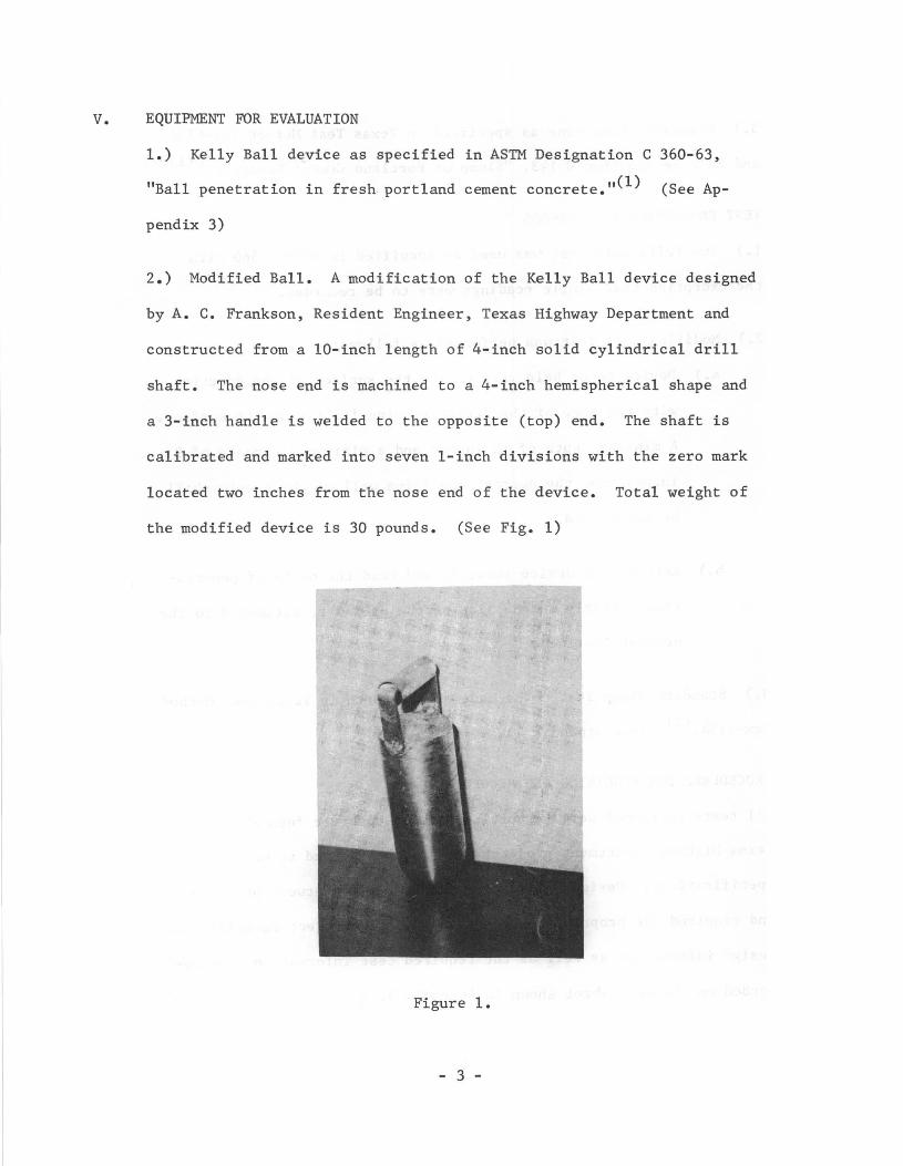
2.) Modified Ball. A modification of the Kelly Ball device designed
by A. C. Frankson, Resident Engineer, Texas Highway Department and
constructed from a 10-inch length of 4-inch solid cylindrical drill
shaft. The nose end is machined to a 4-inch hemispherical shape and
a 3-inch handle is welded to the opposite (top) end. The shaft is
calibrated and marked into seven l-inch divisions with the zero mark
located two inches from the nose end of the device. Total weight of
the modified device is 30 pounds. (See Fig. 1)
Figure 1.
- 3 -

VI.
3.) Standard slump cone as specified in Texas Test Method Tex-415A
and ASTM Designation C 143, "Slump of Portland Cement Concrete. "(1) (2)
TEST PROCEDURES AND METHODS
1.) The Kelly Ball Test was used as specified in ASTM C 360 with
the exception that single readings were to be recorded.
2.) Modified Ball Test was performed as follows:
a.) Device to be held vertical to the surface of the concrete
with the nose of the device resting lightly on the surface.
A minimum depth of 12 inches and a minimum clearance of 9
inches from the nearest confining wall of the sample shall
be maintained.
b.) Release the device smoothly and read the depth of penetra
tion directly on the side of the cylinder, estimated to the
nearest 1/4-inch.
3.) Standard Slump Test to be made as set forth in Texas Test Method
Tex-415A. (Z) (See Appendix 4)
VII. PROCEDURES FOR ACQUIRING AND RECORDING DATA
All tests performed were on portland cement concrete furnished on
Texas Highway Department projects which were required to meet all
specifications. Design and mix conditions varied between projects
and required the proper grouping of test data. Project materials and
design information as well as the required test information were re-
corded on the data sheet shown in Appendix 5.
- 4 -

The Kelly Ball test had previously been determined by Kelly and
Polivka(3) to yield a reading which was roughly one-half that of the
Slump Cone. Similarly, Frankson had experimentally determined that
the Modified Ball reading was approximately twice the value obtained
with the slump cone. Therefore, for the purpose of this investiga-
tion, all readings taken with the two ball devices were adjusted by
either dividing or multiplying by a factor of two, depending upon
the device used.
On all but one project, concrete consistency was measured using the
three devices each time a measurement of slump was required by the
specifications. In the case of the exception, a number of measure-
ments were made with the Slump Cone and the Kelly Ball over a period
of several days and then the modified ball and the Slump Cone values
were measured during a subsequent number of days. In addition for the
same exception, the values reported were all averages of three readings
instead of individual readings. Information developed on this project
was extensive and is utilized in so far as possible in this report,
however, some of the value was negated because of the inability to
compare directly with the other projects data.
VIII. DISCUSSION
The Ball Penetration Test for the consistency of plastic portland
cement concrete was developed a number of years ago and adopted as a
tentative method C 360 by ASTM in 1955. It became a standard in 1963
- 5 -
and reapproved without change in 1968. AASHO adopted the method as a
standard with the assigned number AASHO No. T 183.
A statistical analysis of the Ball Penetration test was made by the
California Division of Highways and reported in 1966. (4
) In addition,
California has adopted a modification of the test as a standard test
method. Similar adoption has been made by a few other State Highway
organizations.
With this background of data and experience there was no need to further
prove the validity of the test when performed as set forth in ASTM C 360.
Instead, this study was directed toward evaluating a modification of the
test procedure and a further proposed modification of the ball device
itself to determine if an abreviated version could satisfactorily assist
the project inspector in speeding up the pre-placement testing of con-
crete delivered to the project.
Two State Highway Districts, Lufkin and Yoakum, had previously indicated
a desire to participate in an evaluation of the Kelly Ball test. One
of the Districts, Yoakum, had already made a limited study with a modi
fied ball device developed by Mr. A. C. Frankson, a Resident Engineer
at Victoria, and requested that the modified ball be included in this
evaluation study. Additional field studies were scheduled to be per
formed at prestress concrete plants located at Victoria by permanently
assigned Materials and Tests Division inspection personnel. Information
gathered by these organizations on plastic portland cement concrete
- 6 -

delivered to State Highway projects forms the data for this investiga
tion. District project data is indicated by "F" and prestress plant
data by "P" in the figures referred to in this report.
Since neither the standard slump cone test nor the standard ball pene
tration test were being questioned as to allowable statistical accuracy,
any proposed change in existing procedures, to be beneficial to project
control, had to provide some tangible reason to support it. This could
be in accuracy, ease of testing, time required for testing or in cost
of testing. The decision had previously been made based on State-wide
studies of existing conditions in concrete bridge decks that the testing
itself was desirable and was reflected in changes in project specifications.
The standard method of performing the Ball Penetration Test is given in
its entirety in the Appendix. Pertinent points of this method are:
1.) Sufficient concrete and area must be available to provide a
minimum depth of 8 in. and a minimum horizontal distance of 9 in.
from the center line of the handle to the nearest edge of the level
surface on which the test is to be made.
2.) A minimum of 3 readings will be made with the foot of the
stirrup moved at least 6 in. from the location for the preceding
reading.
3.) If the maximum and minimum readings are more than 1 in. apart,
additional readings shall be obtained until three successive read
ings agree within 1 in.
- 7 -
The State of California modified the test method to require that
the minimum horizontal distance will be 9 in. between centers on
readings.
With the need to use only acceptable concrete, the emphasis is on
testing the concrete prior to placing in the forms and it is
readily seen that a rather large amount of concrete must be dumped
into an area suitable for test. This concrete must then be wasted
or handled economically in such a manner that it can be used if
approved.
It was readily apparent that performing the test by the standard
methods would increase testing time and cost without yielding a
corresponding benefit of accuracy, consistency or ease of testing,
i.e., the change would hinder rather than help.
The decision was then made to evaluate single readings against
values obtained with the standard slump cone test. Admittedly,
the results obtained would not be as statistically sound but if a
relationship could be established without excessively broadening
the limits set by the specifications, then it might be possible to
use the penetration test for project control by periodically cor
relating the test with the standard slump cone test. A precedent
for this type of control had previously been established for
another physical test of plastic concrete with the successful
adoption of the Chace Air Meter for determining the amount of
entrained air.
- 8 -
Data was then accumulated over a two year period as projects speci
fying portland cement concrete were placed under active construction.
This data has been sorted by project, design and materials and ex
amined on an individual basis.
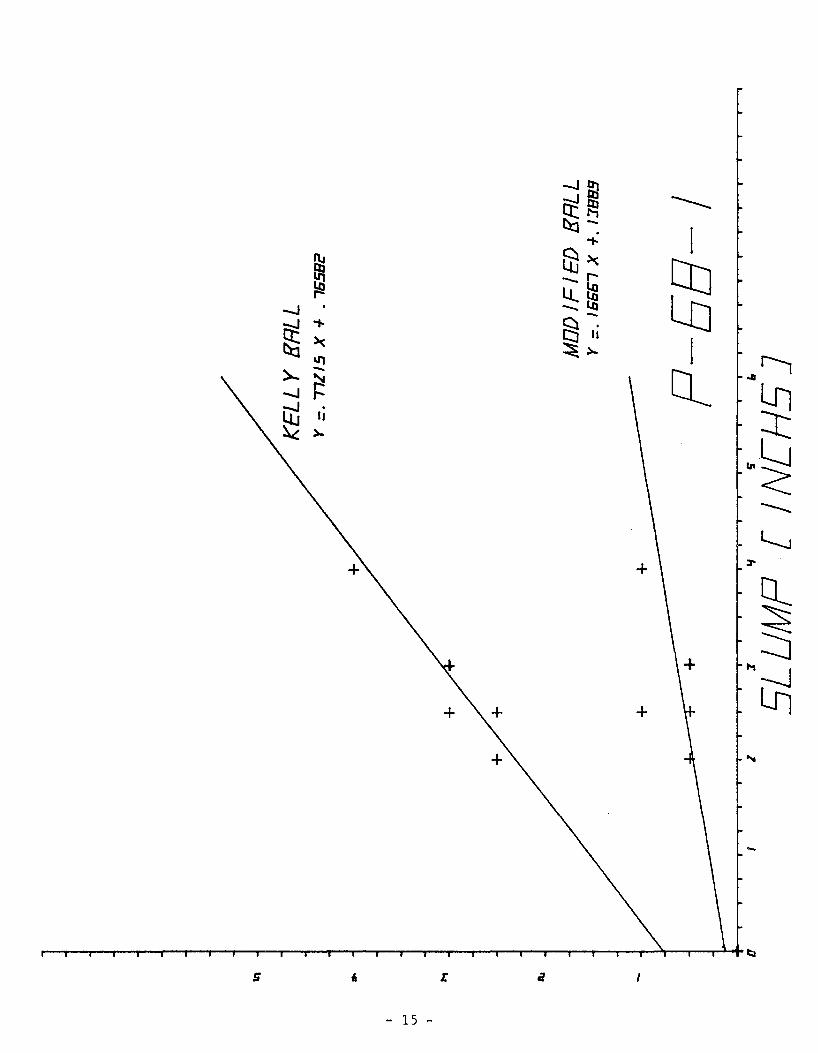
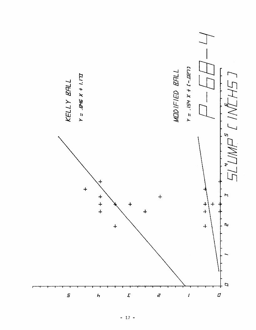
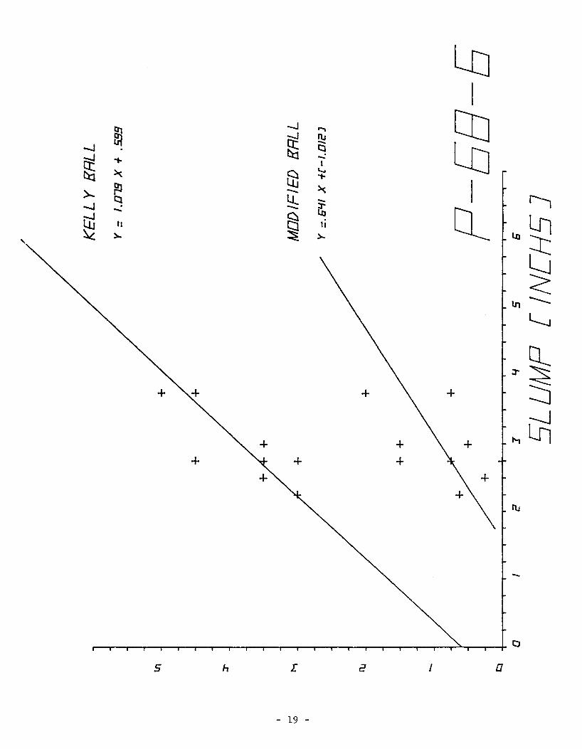
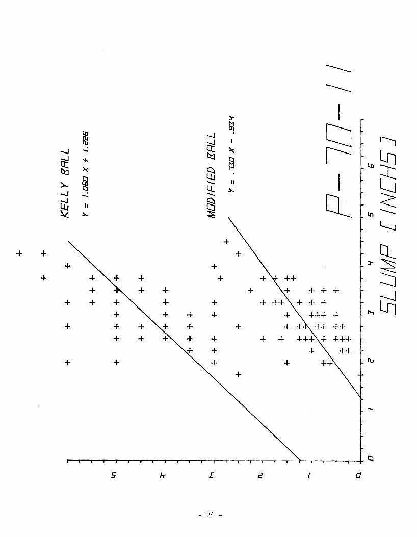
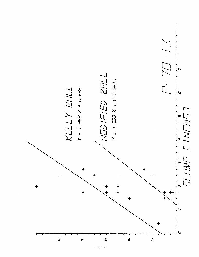
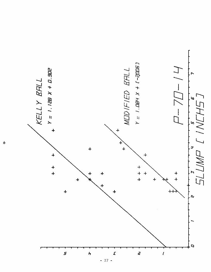
Linear regression analysis comparing values obtained using the
Kelly Ball and modified ball devices with those obtained by the
standard slump cone were calculated and plotted graphically for
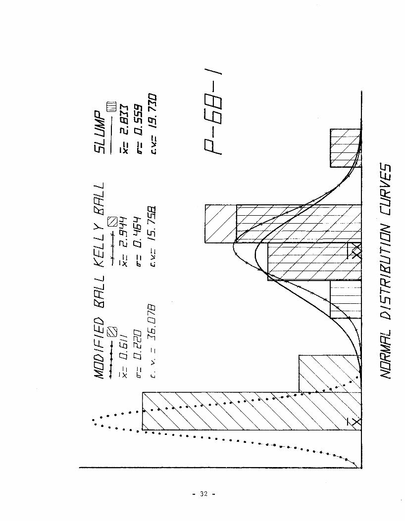
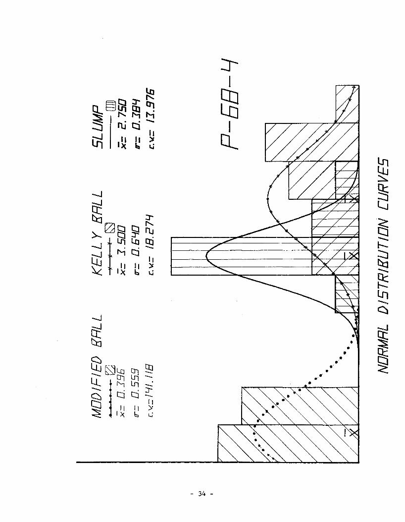
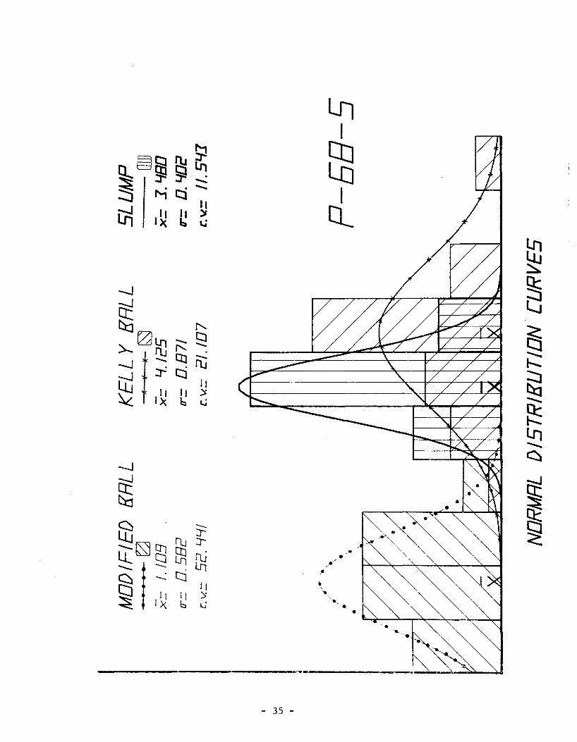
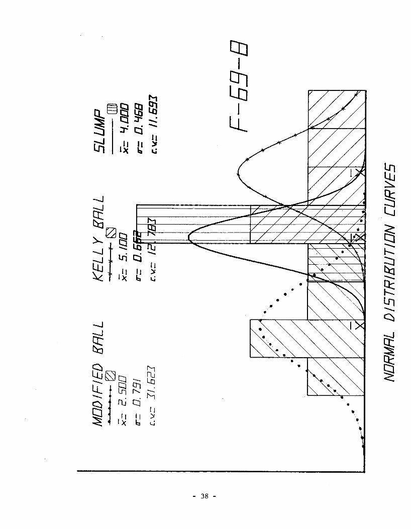
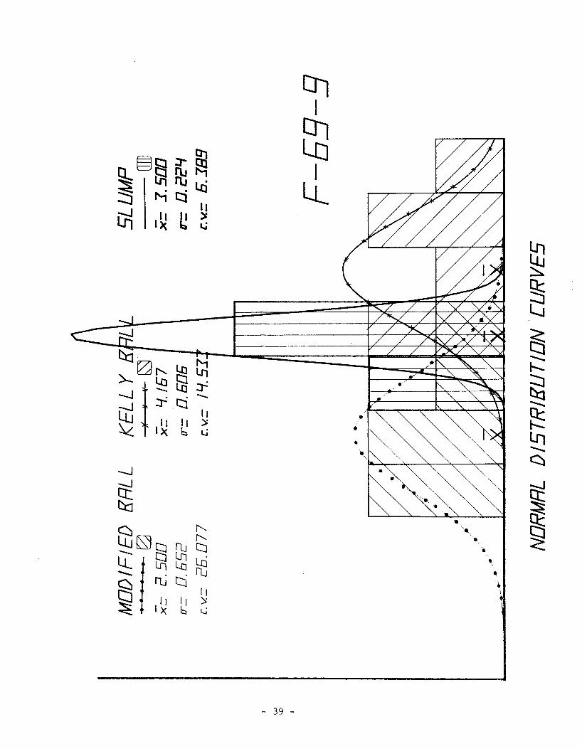
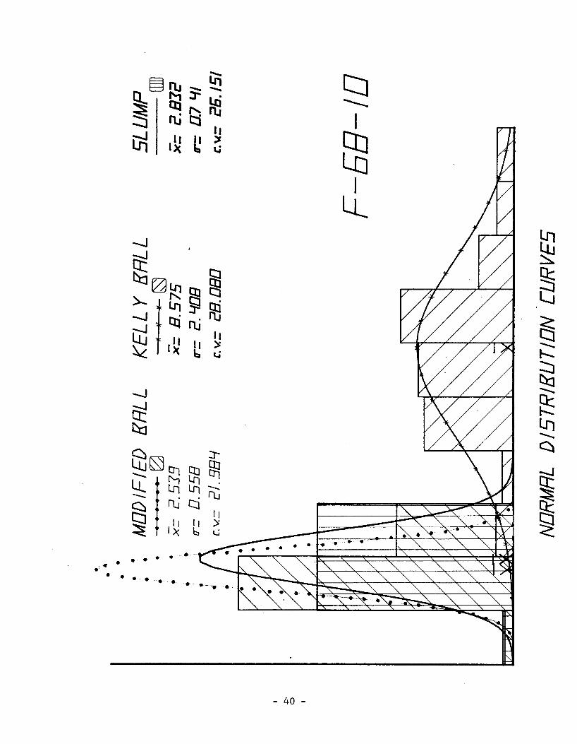
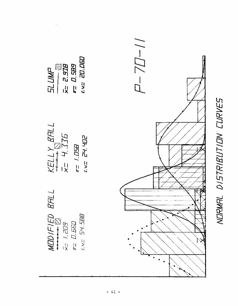
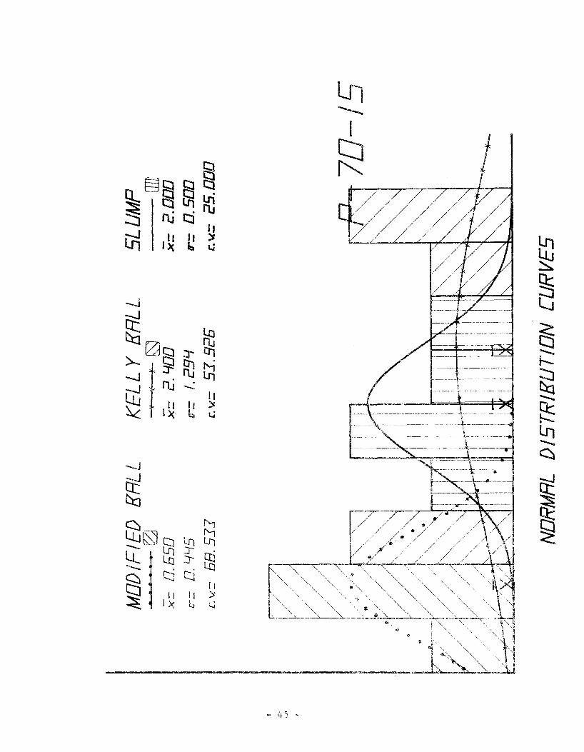
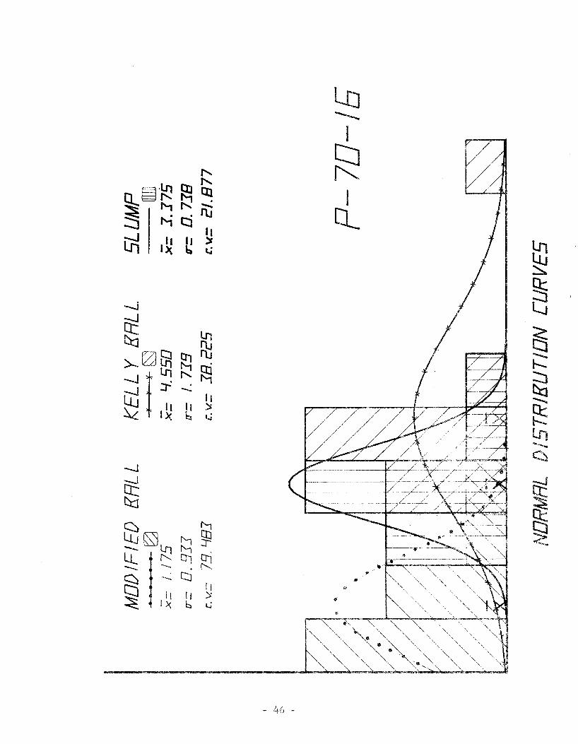
each project. (See Appendix 1) In addition, the normal distribu
tion curves of slump, Kelly Ball penetration and Nodified Ball
Penetration were plotted to show degree of uniformity and compara
tive values. (Appendix 2)
It is readily apparent upon reviewing the normal distribution
curves that when making an analysis based upon single readings,
only the routine slump test consistently has a desired pattern.
In statistically comparing the three methods of measurements by
use of the coefficient of variation (c.v.), in thirteen of the
16 test conditions \vhich have sufficient data for comparison,
the c.v. is considerably lower for the slump cone test than for
the corresponding c.v. for either ball penetration test.
A careful look at the graphs of the linear regression analysis
indicates there is little direct relation between either ball
penetration test and the slump cone test when based on single
readings.
- 9 -

Table I is a summary of the statistical analyses developed through
the linear regression procedure to show the widespread and dis
jointed values which make a general correlation impossible. The
columns headed MB/SL and KB/SL are individual comparisons of the
ratios of the average values ( x ) for each of the ball penetration
tests to the standard slump cone test.
The total result of this study can be simply stated that the
standard slump cone test, as specified presently by the Texas
Highway Department for measuring the consistency of plastic portland
cement concrete, is the only reliable and is the most accurate
method of the three studied. To attempt to extend either ball
penetration test to obtain greater accuracy would not make either
method more reliable than the slump cone test and would so extend
the time and material required to make them undesirable in com
parison with present procedures.
- 10 -
ACKNOWLEDGEMENTS
Personnel from both the Yoakum and Lufkin Districts along with the
Structural Section of the Materials and Tests Division were directly
responsible for the accumulation of data from active project control
which formed the basis for this report.
In addition, Mr. A. c. Frankson of the Yoakum District contributed
much through his efforts to design and manufacture a simplified device
which had the potential to enable the Department to properly perform
its function at a reduced expense.
- 11 -

Project #
P-68-1 P-68-2 P-68-3 P-68-4 P-68-5 P-68-6
I-' P-68-7 N F-69-8
F-69-9 '''F-69-10
P-70-11 P-70-12 P-70-13 P-70-14 P-70-15 P-70-16 P-70-17
Table I
Summary of Statistical Determinations
X s.d. H. B. K.B. S.L. S.B. K.B.
0.611 2.944 2.833 0.220 0.464 0.806 3.850 3.088 0.767 0.975 Insufficient Data 0.396 3.500 2.750 0.559 0.640 1.109 4.125 3.480 0.582 0.871 0.875 3. 778 2.944 0.656 o. 712 1. 292 4.688 2.833 0.504 0.762 2.500 5.100 4.000 0.791 0.652 2.500 4.167 3.500 0.652 0.606 2.539 8.575 2.832 0.558 2.408 1.209 4.336 2.938 0.660 1.058 1.234 4.500 2.500 0.628 0.926 0.977 3.545 2.000 0.834 1.150 1.291 4.333 3.042 0.881 1.260 0.650 2.400 2.000 0.445 1.294 1.175 4.550 3.375 0.933 1. 739 1.326 5.000 3.514 0.780 1.534
Where i = Average reading w/device s.d. = Standard deviation c.vo = Coefficient of variation
S.L. M. B.
0.559 36.078 0.508 95.105
0.384 141.118 0.402 52.441 0.512 74.915 0.537 39.002 0.468 31.623 0.224 26.077 0.741 21.984 0.589 54.588 0.327 50.903 0.403 85.386 0.708 68.188 0.500 68.533 0.738 79.483 0.793 58.821
c.v. K.B. S.L. MB/SL
15.758 19.730 0.216 25.316 16.464 0.261
18.2 74 13.976 0.144 21.107 11.543 0.319 18.847 17.389 0.297 16.261 18.937 0.456 12.783 11.693 0.625 14.533 6.389 o. 714 28.080 26.151 0.897 24.402 20.065 0.412 20.574 13.093 0.494 32.439 20.156 0.489 29.083 23.290 0.424 53.926 25.000 0.325 38.225 21.877 0.348 30.679 22.561 0.377
M.B. = Modified Ball K.B. = Kelly Ball
KB/SL
1.039 1.247
1. 273 1.185 1.283 1.655 1.275 1.191 3.028 1.476 1.800 l. 773 1.424 1.200 1.348 1.423
S.L. = Standard Slump Cone

BIBLIOGRAPHY
1.) ASTM Standards, Part 10.
2.) Texas Highway Department Standard Testing Procedures, Vol. 2.
3.) "Ball Test for Field Control of Concrete Consistency" by
Kelly and Polivka; Journal of the American Concrete Institute,
May 1955.
4.) "A Statistical Analysis of the Kelly Ball Test" by the General
Services Section, Materials and Research Department, Department
of Public Works, Division of Highways, State of California, Oct.
1966.
- 13 -

APPENDIX 1
- 14 -
-Jgj
----~f!l I ttl-: ....
U1~ cg ~ -r-Llf:g ta -lll -
r-
8 ti
-J
I r-,
~ .... ~.)... ~~
Q .OWl -;:t
~ ~ -J r-
~·~ u1 .
It
~ .)...
-........
~ + 3"
~ :j
..,~
lrl
-
s ' il I
- 15 -

ru I
,_, r-, 85 :r-
~ :r-
-.I S:! r--, -.I . ~ I n.i
~ " ~ I I ~~ .... ...... ttl ....
~ ED ~
Q :>.. ~ ~ -.I - ~ ll
Qj 1:::1 - - .....:
B ~ It It ).. ~ )..
..,..__ ~
+ + + ~~ + :j
+
)~ + + + +
+ +
+ +
-
5 I a
- 16 -
:r-I
,......
85 J::l -.J r-
~ ~ r--, -.J - .
~ ....: ttl I
~ '-;. ;.
~ ::..; tD ~ I :>.. ~ - ~ ~ ll .....j Ell - Q_ ~ . .
II B II
~ ).. ~ )... ---~ t.n
Q s :r-
~ +
+
5 h I a
- 17 -

Ln I
-..J ...,
ffi ~ r-
~ ih -..J ,.., .....: ttl .
~ I
...... .... EG
.... bd ~ ~ I >.. ~ - ~ lL r-, -..J - :r-
Q ~ B .
~~ II II
~ ).. ~ )..
~ tn--
~
+ + + ~~ + t + ++ :j
+ + + + + +
~LR + + + + + ++ + +
+ + +
5 h I a
- 18 -
ltJ I
m -.J .......
83 ~ rt.J --.J t::l
~ .... t:t:i ....: I
~ 6J ""' t:t:i .... ~ ~ I ~ -t::l lL - r--, -.J . - a; Q -qj II B li
~ ~ ~ ~ )... lQ '
~ lrl --~ ~~ :j
~~
5 h I a
- 19 -

r----I
8 -.J
rn f-J ~ :r--.J n.i ttl fB
~ fi .... ~
l.Q ~ ~ ~
I >.. r- - r-
~ :r- Ll.. Pd -.J 0, - Q qj II B It
~ .)... ~ .)... lrt --~ ~~ :j
+ + ~~ +
+
+
-
5 h 2 I a
- 20 -

ctJ I ....,
~ -.J ~
rn ~ ....: r--, ....: I
~ '-.,
~~ .... .... -J ~ 6J ~
~ § § I ~ - ~ ll >- ....: - ....:
lL -J B i:rl It It
~ ).. ~ ).. lrt--~
+ + ~~ :j
~~
5 h I a
- 21 -

en !"'" I -a,
-..J lri
rn ~ "1- r-, ~ ttl ~ ....,
~ ~~ -..J lri )....
~ I .
ttl ~ II I ~ ~ )..
~ LL - nj lL It lrt---~ ).. ~
~~ + :j + +
~~ + +
5 h I a
- 22 -

..., ,_
~ tJ ~ -.1
-...J ~ ---m ~tif ~ Cl t'J I -J ~~ . ~ . - ~ ~
~ !~ E8 .....
63 -t- ~ t.ai-J
~ ~ ~ f1l
~ ...... &~ -- "' ~ LL. -J ~ ~~ -- iJ1 ~ I wj
. B lL - m~ 1::1 ~ ~·~ ~ ~
:s; ~ ~ ~ +
Q:\, ct
---~ + ++ ~
+ + + ~ + + + + ,.,:::J
+
~ + ++ + + +
"· + + + ++ ++ + + +
+ + +
+ -
5 h I
- 23 -
--------.:r- I
te &1
~ -.J
~ ru ~ I
-.J - ~
~ ~ .... ttl ~ ll:J
ttl ~ 6J r-'
@ I ).... ......... II
~ 1::1 lL .).. -.J - .........
Q ~ II B ~ .).. ~ lr1 ...............
l-...J +
~ + + + + + .:r-
+ + + ::j + + + + + +
~~ + + + + + + + + + + +
+ + + + + + + + + +
+ + + + +
+
s h I a
- 24 -

ru ----
I r--, ~ -...1 [X ~ ~~ 2l ~ ~ -...1 ;:r:
~ ttl
~ '1- '1-
ttl ~ EG ~ ...... ...... I ~ tg
..._ -Lt. :n tn -...__
-...1 - - Q_ ~ .
B ~ II II
~ ~ ~ ~
~~ :j
+ ~~ + +
+ + + +
+ +
s h I a
- 25 -
f'j .....__
I
-J ~ ~
......,
I --.....1 ru ~ Q. tJ:j
~ lJ:i -. I t:l
EG ~
C:t] ;.. ;..
~ ~ r,-,
>- --lli l1_ rti tnWl -.....1 ::r- -- flj
c= qj . - -
II It ~ ~ >-. )....
~----~
,.., Q~ + + s + + +
+ + ~~ + +
+
.....
s h I
- 26 -
r-,
~ -..J t3 :J ~ 2 0'1 ----.J . I
t:l ttl ~
~ I ... ,... ~ ~ 6J ~
~ t.Q~ m :r->.. -- ~ ~ - lL. -.J . -- .
I - B -Qj II IJ Q_ ~~ ~ .)... ~ .)...
+ -...._
+ ~ + ;,-
~ + + ,.,:::J + + + + +
~ + + + :+ +
+
5 I
- 27 -

Ln !Jlr--, ,..., --- ~
~ -.J
61 I Ol
f:i .
~ -...J . 9 ~~ -f:i ~ t.......
..... ..... t:tl ~ 6J ~ I --->... ~ -- ~ ll ~
ru ~ -J c:i
1\J :r-
Qj --8 Cl ~ II II
~ ~ ~ .)... ,.,=:J + ~
+
s E I
- 28 -
)

"' l(] ~ -J ;;:;
~ .
fl.J ---Oi I -J . tti
~ I'll
~ I I
ED t.n
~ -~r--.,
t:ti ~ t:J . ~ ...._ -
~ >.. lL - II
I -J . ...._
I'll -~ ;)... Qj IJ
+~ CL ~~ ~ ;)...
--. ~
+
~ + + +
+ ~::j + ~
s h E I
- 29 -

-J ~
~ ~ I1J ...............
~ Cl I .......
6J ~ h] ~ -.... @ -J ~ lL
~ . -.... 1'1
I ~~ .....
B .
....... Cl ttl ~ ll ~ ~ >-.. ~ + + -.J Cl ~~ wj
. -~ ~ + ~
+ + ~ + + + :r-
+ + + ~ + + + + + + + + + ,.,:::J
+ +
~ + + + + + +
+
5 I I
- 30 -

APPENDIX 2
- 31 -
••• • • • • • • • ••••••••
---I ffi I
Cl_
• • • •
- 32 -
• • • • • ._ ... --- ·-.. . . . ·····"'

- 33 -
-..I
~ tt:j ::r-~08§J~ --.I t lti Lo tJ::i ~ f'.-j c:j -~ II ~ 111 11 )>
X b &..i
-.j
~ ttl
EG -- (S]La ~ to lL OJ Lri :::::: ~I~~~ ~ t:j t:j :::r-~ II ~
111 11 )t X 6 t_;
- 34 -
::r-1
83 I
Q_
tD ~
~ l_j
·;;=: t::j --........
~ --g: lr1 --c::::.
• ~ • • ~ • • • ~ •..
• •
Ln I
t-1 ~§@2:{[h E8 ~ :::r-: :::r-: -.: :::::5 1'-i E:::i -..
~ I~ I II
I ~ ~ a.; CL
tfJ ~
-...J
~ ~
~ " ).... 0 t..n -.. t:J
L.J
f'Li"-.
-J r-- OJ -:
~ :-..J :r= tj fl.J
~ IJ I 1!
-.....
tx ~ ~
......._
~ -..... ~ Lrt -..... ~
-.J
fi t:ci
EG . :r:
~ ~
Q:rsJ~Hs~ _t_Ul~
~ ~ -:t::i
~
~/
~ ,, •
~ ,'' lj );
• '·
)( 6 L..j
'9
• ...
..
r~-
- 35 -

- 36 -
La I
ffi I
CL
• •

- 37 -
- 38 -
CtJ I
m I
lL
• •
•
to ~
~ l.J
::-..J
ttl· >-0"~[ri
~
--Jr~tct~ ~ :r= c::j .._
........
~ It
.......
~ 1tt It~
~ X b l..i
........ g: lr1 ........ ~
-.J
~ ~
ED ~
~
--~~rut; ~
~~ ~ Cil LJj
'• ' ~ ~ i1J t:i ru
• 'a
~ I ,, II
~.
I~ :>
• 6 t_;
•
- 39 -
... •
...... • •
- 40 -
t:J ---1
E8 I
lL.
- 41 -

- 42 -

- 43 -

:r----I . tl ~
g._s9:!!,1Jm ~ t::l~~ ::::5 1'1 t:j rti
I
~ II CL
l.i1 1~ II ~ 1::1 l..i tn
~
-....1
~ ~ t'-1
~
>-- tZJ~ ~ ~
lJ
-J!M~g; ~
:-.J :r= . llj W..J -.. It ~ Ill It )t
h
X b l..i
~ ...........
~ lrl ........... ~
-.I
~ t:ci
EG~sr-
~
85
g;l~ --~
§3cti ~ -- c::ilrj
• ~ ,/
~ ~~
, I I
Jl
II :::;
:
1:::, L.i
• • •
- 44 -
··------------ 46 -

- 47 -

APPENDIX 3
- 48 -
Designation: C 360 - 63 (Reapproved 1968) American National Standard A37.92-1964 (R 1969) American National Standards Institute
Standard Method of Test for
American Association State Highway Officials Standard
AASHO No.: T 183
BALL PENETRATION IN FRESH PORTLAND CEMENT CONCRETE 1
T~is Standar~ is. issued under the fixed designation C 360; the number immediately following the designation indicates the Y1
ear of ongmal adoptiOn or. m the case of rev1s1on. the year of last revision. A number in parentheses indicates the year of ast reapproval. ·
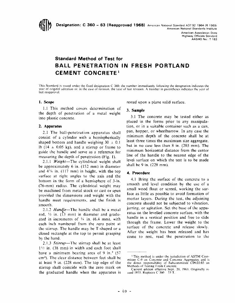
1. Scope
1.1 This method covers determination of the depth of penetration of a metal weight into plastic concrete.
2. Apparatus
2.1 The ball-penetration apparatus shall consist of a cylinder with a hemispherically shaped bottom and handle weighing 30 ± 0.1 lb ( 14 ± 0.05 kg), and a stirrup or frame to guide the handle and serve as a reference for measuring the depth of penetration (Fig. 1 ).
2.1.1 Weight-The cylindrical weight shall be approximately 6 in. (152 mm) in diameter and 4% in. (117 mm) in height, with the top surface at right angles to the axis and the bottom in the form of a hemisphere of 3-in. (76-mm) radius. The cylindrical weight may be machined from metal stock or cast or spun provided the dimensions and weight with the handle meet requirements, and the finish is smooth.
2.1.2 Handle-The handle shall be a metal . " rod, 1/2 tn. ( 13 mm) in diameter and gradu-
ated in increments of 1/4 in. (6.4 mm), with each inch numbered from the zero point at the stirrup. The handle may beT -shaped or a closed rectangle at the top to permit grasping by the hand.
2.1.3 Stirrup-The stirrup shall be at least ! 1/2 in. (38 mm) in width and each foot shall have a minimum bearing area of 9 in. 2 (57 cm 2
). The clear distance between feet shall be at least 9 in. (228 mm). The top edge of the stirrup shall coincide with the zero mark on the graduated handle when the apparatus is
rested upon a plane solid surface.
3. Sample
3.1 The concrete may be tested either as placed in the forms prior to any manipulation, or in a suitable container such as a can, pan, hopper, or wheelbarrow. In any case the minimum depth of the concrete shall be at least three times the maximum size aggregate, but in no case less than 8 in. (203 mm). The minimum horizontal distance from the center line of the handle to the nearest edge of the level surface on which the test is to be made shall be 9 in. (228 mm).
4. Procedure
4.1 Bring the surface of the concrete to a smooth and level condition by the use of a small wood float or screed, working the surface as little as possible to avoid formation of mortar layers. During the test, the adjoining concrete should not be subjected to vibration, jarring, or agitation. Set the base of the apparatus on the levelled concrete surface, with the handle in a vertical position and free to slide through the frame. Lower the weight to the surface of the concrete and release slowly. After the weight has been released and has come to rest, read the penetration to the
1 This method is under the jurisdiction of ASTM Committee C-9 on Concrete and Concrete Aggregates and is the direct responsibility of Subcommittee C09.03.03 on Methods of Testing Fresh Concrete.
Current edition effective Sept. 20, 1963. Originally issued 1955. Replaces C 360 - 55 T.
- 49 -
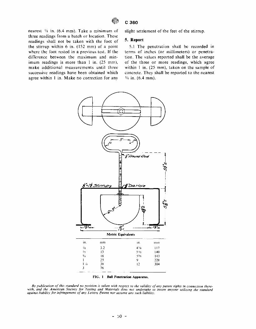
nearest 1/4 in. (6.4 mm). Take a minimum of three readings from a batch or location. These readings shall not be taken with the foot of the stirrup within 6 in. (152 mm) of a point where the foot rested in a previous test. If the difference between the maximum and minimum readings is more than l in. (25 mm), make additional measurements until three successive readings have been obtained which agree within l in. Make no correction for any
i"><li .5tiri'7Jp
I-/ , B' 12'
c 360
slight settlement of the feet of the stirrup.
5. Report
5.1 The penetration shall be recorded in terms of inches (or millimeters) or penetration. The values reported shall be the average of the three or more readings, which agree within l in. (25 mm), taken on the sample of concrete. They shall be reported to the nearest 114 in. (6.4 mm).
2::kz Holt!'
] ' I ..,I!() If)
~ j L_ ~
Metric Equivalents
in. mm in. mm l/8 3.2 4% 117 l/2 13 5112 140 % 16 5 .Ys 143 1 25 9 228 [l/2 38 12 304 3 76
FIG. I Ball Penetration Apparatus.
By publication of this standard no position is taken with respect to the validity of any patent rights in connection therewith. and the American Society for Testing and Materials does not undertake to insure anyone utilizing the standard againstliabi/itv for infringement of any Letters P.atent nor assume any such /iabilitv.
- so -

APPENDIX 4
- 51 -
Test Method Tex-415-A
Rev: September 1966
Texas Highway Department
Materials and Tests Division
SLUMP OF PORTLAND CEMENT CONCRETE
Scope
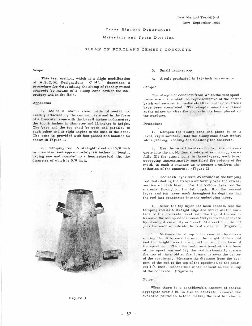
This test method, which is a slight modification of A. S. T. M. Designation: C 143, describes a procedure for determining the slump of freshly mixed concrete by means of a slump cone both in the laboratory and in the field.
Apparatus
1. Mold: A slump cone made of metal not readily attacked by the cement paste and in the form of a truncated cone with the baseS inches in diameter, the top 4 inches in diameter and 12 inches in height. The base and the top shall be open and parallel to each other and at right angles to the axis of the cone, The cone is provided with foot pieces and handles as shown in Figure 1.
2. Tamping rod: A straight steel rod 5/8 inch in diameter and approximately 24 inches in length, having one end rounded to a hemispherical tip, the diameter of which is 5/8 inch.
Figure 1
52 -
3. Small hand-scoop
4. A rule graduated in 1/8-inch increments
Sample
The sample of concrete from which the test specimens are made shall be representative of the entire batch and secured immediately after mixing operations have been completed. The sample may be obtained at the mixer or after the concrete has been placed on the roadway.
Procedure
1. Dampen the slump cone and place it on a level, rigid surface. Hold the slump cone down firmly while placing, rodding and finishing the concrete.
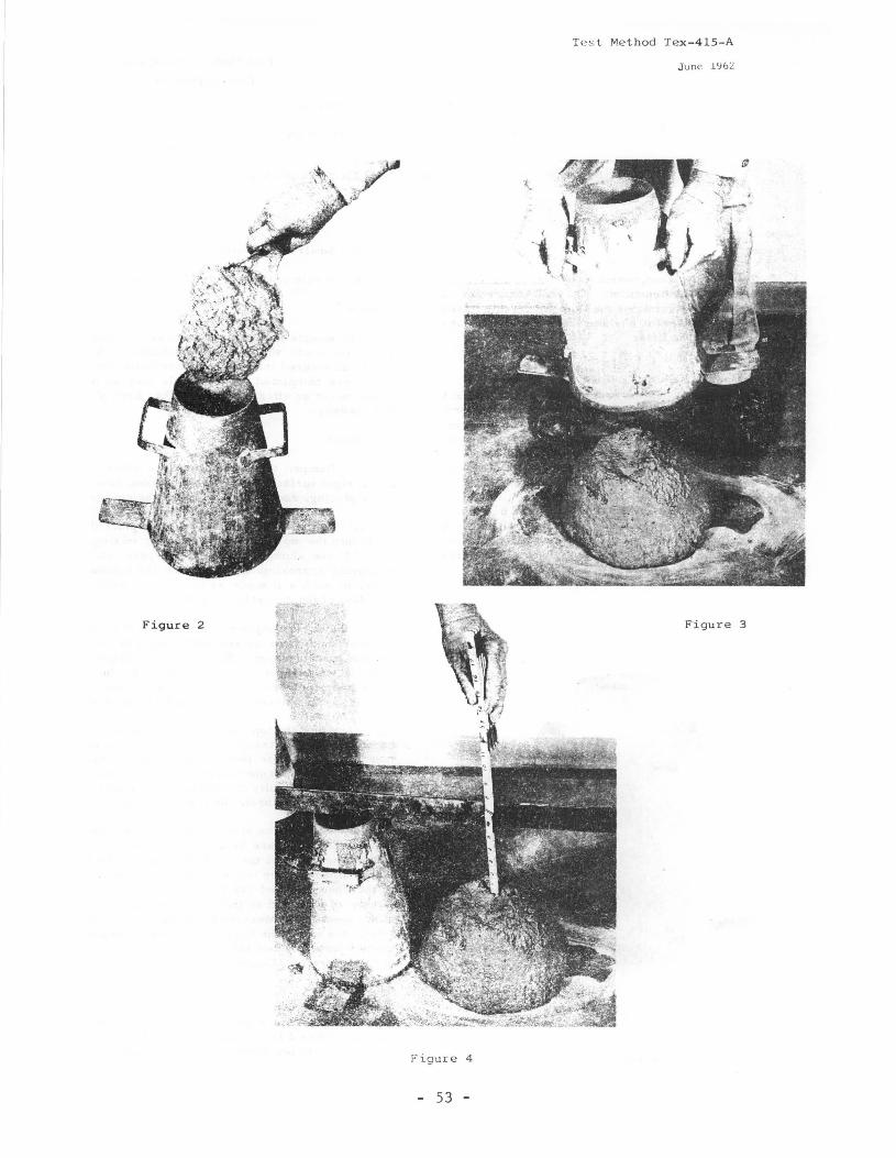
2. Use the small hand-scoop to place the concrete into the mold. Immediately after mixing, carefully fill the slump cone in ·three layers, each layer occupying approximately one-third the volume of the mold, in such a manner as to secure a uniform dis- . tribution of the concrete. (Figure 2)
3. Rod each layer with 25 strokes of the tamping rod distributing the strokes uniformly over the crosssection of each layer. For the bottom layer rod the material throughout the full depth. Rod the second layer and top layer each throughout its depth so that the rod just penetrates into the underlying layer.
4. After the top layer has been rodded, use the tamping rod as a straight edge and strike off the surface of the concrete level with the top of the mold. Remove the slump cone immediately from the concrete by raising it carefully in a vertical direction. Do not jerk the mold or vibrate the test specimen, (Figure 3)
5. Measure the slump of the concrete by determining the difference between the height of the mold and the height over the original center of the base of the specimen. Place the 'mold on a level with the base of the specimen and lay the rod horizontally across the top of the mold so that it extends over the center of the specimen. Measure the distance from the bottom of the rod to the top of the specimen to the nearest 1/ 4-inch. Record this measurement as the slump of the concrete. (Figure 4)
Notes
When there is a considerable amount of coarse aggregate over 2 in. in size in concrete, remove the oversize particles before making the test for slump.
Tes t Method Tex-415-A
J une l\1 6Z
Figure 2 Figure 3
Figure 4
- 53 -

APPENDIX 5
- 54 -

DATA SHEET KELLY BALL AND HODIFIED BALL TEST EVALUATION
District No. : Tests Performed by: County: Project: Highway:
(Cr./Uncr.) C.A.: _______ Type--------- Source _______ _ F. A. : ________ Type Source ____ _ Admixtures: Type Source ------Cement: Type Source Class Concrete: Design ·s-trength: (psi) Design: (1-Sack) (c. f.) C. A. : CAF Sp. Gr. ------- Unit Wt. -----
Unit Wt. % Solids % Solids F.A.: FAF Sp.Gr. ---- ----- ----
Cement C/F ----------- ---------Water W/C ---------Air % Air ------Retarder % Water Reduction Transit Nix: (Yes, No) Length of Haul:
---~------
Mixing Time:
Kelly KBV Hod. MBV Test Moisture (%) Ent. Ball x 2 Ball + 2 Slump Cone
~N~o~·-r~D~a~te~--+--F_._A_.-t_~C~·~A~·~-~A=i=r~(~%~)_\~Ta=l=u=e~~(i~n~·~)~(~i~n~·~)~~V=a=l=u=e~(=i=n-·~~)~~(l=·n~.)~~--\ __ 7D_1ue (in~l
----+---~---4----+--------+----------+-----4---------~-------~---------------
-----+-----~---~--~-----~-------~-----+------------------~~---------
-----+-----+------l------+-----j----------t------r-------~-t-------t------------
----t----4-----+----+------t---------~-----+---------~---------+------------
----------~-----~----~-----~--------~------r-----------+------~---------------------~-----r-----~-------~------+-------1------------4--------~-----------
-----1--------+------+----+--------------t------y-------- -----------r---------+--------------
-----1-------+------f----- r-------+--------+-------t---- -----1-----------+----------------+----- ->------+------1-------·------+----------t-------t----------1-------+------------
:_ ______ f---i- -~----+--f---~-~-=---~--~--~-~f------_---_ -_ -_ --tl-----__ --__ -t--~--=-========1--f--------_-_____ _ ------ ------ - -- ----------1----- --------------- ----------t-------------
-4----- -------~---------+-----~f-- --------+----------~------------
~~,~-~t=,----+- -- -------= -~- -~------- ------=--=--==~==--~
~--~-=~-~+~===~--=-~~,~~i~~:~~j=~-=~4-s~~~- =--~==~.~ - 55 -