evaluations and enhancements in 802.11n wlans â•fi error
TRANSCRIPT

San Jose State University San Jose State University
SJSU ScholarWorks SJSU ScholarWorks
Master's Projects Master's Theses and Graduate Research
2009
Evaluations and Enhancements in 802.11n WLANs – Error-Evaluations and Enhancements in 802.11n WLANs – Error-
Sensitive Adaptive Frame Aggregation Sensitive Adaptive Frame Aggregation
Ken Chan San Jose State University
Follow this and additional works at: https://scholarworks.sjsu.edu/etd_projects
Part of the Computer Sciences Commons
Recommended Citation Recommended Citation Chan, Ken, "Evaluations and Enhancements in 802.11n WLANs – Error-Sensitive Adaptive Frame Aggregation" (2009). Master's Projects. 79. DOI: https://doi.org/10.31979/etd.q3ca-upt3 https://scholarworks.sjsu.edu/etd_projects/79
This Master's Project is brought to you for free and open access by the Master's Theses and Graduate Research at SJSU ScholarWorks. It has been accepted for inclusion in Master's Projects by an authorized administrator of SJSU ScholarWorks. For more information, please contact [email protected].

Evaluations and Enhancements in 802.11n WLANs – Error-Sensitive Adaptive Frame Aggregation
A Project Report
Presented to
The Faculty of the Department of Computer Science
San Jose State University
In Partial Fulfillment
of the Requirements for the Degree
Master of Computer Science
By Chan, Ka Ho (Ken)
Spring 2009

Ken Chan Advisor: Prof Melody Moh
CS298 Report, Spring 2009 May 03, 2009 1
Copyright© 2009 Chan, Ka Ho (Ken) All Rights Reserved

Ken Chan Advisor: Prof Melody Moh
CS298 Report, Spring 2009 May 03, 2009 2
APPROVED FOR THE DEPARTMENT OF COMPUTER SCIENCE
_______________________________________ Advisor: Professor Melody Moh
_______________________________________
Professor Sami Khuri
_______________________________________ Professor Mark Stamp

Ken Chan Advisor: Prof Melody Moh
CS298 Report, Spring 2009 May 03, 2009 3
Abstract
IEEE 802.11n is a developing next-generation standard for wireless local area network (LAN). Seamless multimedia traffic connection will become possible with the 802.11n improvement in the Physical and MAC layer. The new 802.11n frame aggregation technique is particularly important for enhancing MAC layer efficiency under high speed wireless LAN. Although the frame aggregation can increase the efficiency in the MAC layer, it does not provide good performance in high BER channels when using large frame aggregation size. An Optimal Frame Aggregation (OFA) technique for AMSDU frame under different BERs in 802.11n WLANs was proposed. However, the suggested algorithm does not take into account the loss rate and the delay performance requirements for Voice or Video multimedia traffic in various BER channels. The optimal frame size can provide good throughput in the network, but the delay might exceed the Quality of Service (QoS) requirement of Voice traffic or the Frame-Error-Rate (FER) might exceed the maximum loss rate tolerable by the streaming Video traffic. We propose an Error-Sensitive Adaptive Frame Aggregation (ESAFA) scheme which can dynamically set the size of AMSDU frame based on the maximum Frame-Error-Rate (FER) tolerable by a particular multimedia traffic. The simulations show that our adaptive algorithm outperforms the optimal frame algorithm by improving both the delay and the loss rate in the 802.11n WLANs. The measured FER of the Error-Sensitive Adaptive Frame Aggregation scheme can be kept at about the same as the loss rate requirement for Video traffic even under high Bit-Error-Rate (BER) channel. The delay compared to OFA is also decreased by around 50% under different channel conditions. Moreover, the results show that the Error-Sensitive Adaptive Frame Aggregation scheme works particularly well in error-prone wireless networks.

Ken Chan Advisor: Prof Melody Moh
CS298 Report, Spring 2009 May 03, 2009 4
Lists of Acronyms ACK Acknowledgement
A-MSDU Aggregated MAC Service Data Unit A-MPDU Aggregated MAC Protocol Data Unit AP Access Point CTS Clear-To-Send DoS Denial of Services
EDCA Enhanced Distributed Channel Access (802.11e) FEC Forward Error Correction HD High Definition IMA Instantaneous Multi-Receiver Aggregation MAC Media Access Control
MCMR Multi Channel Multi Radio MCS Modulation and Coding Scheme
MIMO Multiple Input Multiple Output NAV Network Allocation Vector
OFDM Orthogonal Frequency Distribution Modulation PCF Point Coordination Function
PHY Physical QAM Quadrature Amplitude Modulation QPSK Quadrature Phase Shift Keying RTS Request-To-Send
SIFS Short Inter-frame Space STBC Space Time Block Coding TGn IEEE Task Group n WLAN Wireless Local Area Network

Ken Chan Advisor: Prof Melody Moh
CS298 Report, Spring 2009 May 03, 2009 5
Table of Contents
1. INTRODUCTION ..........................................................................................................................7 1.1. DESIGN GOALS FOR IEEE 802.11N........................................................................................7 1.2. DEVELOPMENT HISTORY FOR IEEE 802.11N.............................................................................8 1.3. MAIN IEEE 802.11N PROPOSALS...........................................................................................8 1.4. INDUSTRY DEVELOPMENT OF 802.11N.....................................................................................8 1.5. REPORT ORGANIZATION ........................................................................................................8 2. BACKGROUND ........................................................................................................................10 2.1. 802.11N PHY LAYER SPECIFICATION....................................................................................10 2.1.1. MULTIPLE- INPUT-MULTIPLE-OUTPUT (MIMO) ........................................................................10 2.1.2. ORTHOGONAL FREQUENCY DIVISION MULTIPLEXING (OFDM) ...............................................11 2.1.3. FORWARD ERROR CORRECTION (FEC) ................................................................................11 2.1.4. SHORT GUARD INTERVALS ....................................................................................................12 2.1.5. CHANNEL BONDING ...........................................................................................................12 2.2. 802.11N MAC LAYER SPECIFICATION..................................................................................13 2.2.1. OVERVIEW OF 802.11 MAC LAYER INEFFICIENCY.................................................................13 2.2.2. A-MSDU FRAME AGGREGATION ........................................................................................14 2.2.3. A-MPDU FRAME AGGREGATION ........................................................................................15 2.2.4. TWO-LEVEL AGGREGATION .................................................................................................16 2.2.5. BLOCK ACKNOWLEDGEMENT (BA) ......................................................................................17 2.2.6. COMPARISONS BETWEEN DCF AND 802.11N FRAME AGGREGATION ....................................17 3. RELATED WORKS ON 802.11N FRAME AGGREGATION ................................................................20 3.1. BOOSTING VIDEO CAPACITY THROUGH MULTIPLE RECEIVER FRAME AGGREGATION.................20 3.2. IMPLICIT SPOOFING .............................................................................................................21 3.3. OPTIMAL FRAME AGGREGATION (OFA) FOR 802.11N WLANS ............................................21 4. ERROR–SENSITIVE ADAPTIVE FRAME AGGREGATION (ESAFA).....................................................23 4.1. RATIONAL...........................................................................................................................23 4.2. DESIGN ..............................................................................................................................23 4.3. IMPLEMENTATION OVERHEADS AND LIMITATIONS....................................................................27 5. PERFORMANCE EVALUATIONS ...................................................................................................28 5.1. SIMULATION SETTINGS ..........................................................................................................28 5.2. PERFORMANCE METRICS: .....................................................................................................28 5.3. EVALUATION BETWEEN OFA AND ESAFA .............................................................................29 6. CONCLUSIONS AND FUTURE WORKS ..........................................................................................34 7. REFERENCES ............................................................................................................................35 APPENDIX A: SIMULATION COMMANDS .............................................................................................37 APPENDIX B: TCL SCRIPTS FOR SIMULATION ........................................................................................38 APPENDIX C: TCL FILE FOR BATCH SIMULATION RUN...........................................................................48
Ken Chan Advisor: Prof Melody Moh
CS298 Report, Spring 2009 May 03, 2009 6
List of Figures FIGURE 1 MAC EFFICIENCY VS INCREASE OF PHY DATA RATE ..................................................................14 FIGURE 2 A-MSDU FRAME FORMAT.......................................................................................................15 FIGURE 3 A-MPDU FRAME FORMAT ......................................................................................................16 FIGURE 4 TWO-LEVEL FRAME AGGREGATION. .........................................................................................17 FIGURE 5 MAC THROUGHPUT WITH DIFFERENT PHY RATES (DCF VS AMPDU) ..........................................18 FIGURE 6 AVERAGE DELAY WITH DIFFERENT PHY RATES (DCF VS AMPDU)...............................................19 FIGURE 7 THROUGHPUT OF ESAFA AND OFA IN DIFFERENT BER CHANNELS...............................................30 FIGURE 8 PERCENTAGE OF THROUGHPUT INCREASED FOR ESAFA OVER OFA ...........................................30 FIGURE 9 AVERAGE DELAY OF ESAFA AND OFA IN DIFFERENT BER CHANNELS .........................................31 FIGURE 10 PERCENTAGE OF AVERAGE DELAY DECREASED FOR ESAFA OVER OFA...................................31 FIGURE 11 PEAK DELAY OF ESAFA AND OFA IN DIFFERENT BER CHANNELS ..............................................31 FIGURE 12 PEAK DELAY IMPROVEMENT OF ESAFA OVER OFA.................................................................32 FIGURE 13 PERCENTAGE OF PACKET WITH MORE THAN 30MS DELAY FOR ESAFA AND OFA IN DIFFERENT BER
CHANNELS...................................................................................................................................32 FIGURE 14 DECREASE IN PERCENTAGE DELAY FOR ESAFA OVER OFA .....................................................33 FIGURE 15 MEASURED FER FOR ESAFA AND OFA IN DIFFERENT BER CHANNELS .......................................33
List of Tables TABLE 1 COMPARISONS FOR 802.11 A/B/G/N STANDARDS........................................................................7 TABLE 2 FER WITH RESPECT TO THE OPTIMAL FRAME SIZE IN DIFFERENT BER CHANNELS ..................................25 TABLE 3 FER WITH RESPECT TO THE DIFFERENT MPDU SUBFRAME SIZE IN BER = 10-6 ....................................25 TABLE 4 FER WITH RESPECT TO THE DIFFERENT MPDU SUBFRAME SIZE IN BER = 10-5 ....................................25 TABLE 5 FER WITH RESPECT TO THE DIFFERENT MPDU SUBFRAME SIZE IN BER = 10-4 ....................................25

Ken Chan Advisor: Prof Melody Moh
CS298 Report, Spring 2009 May 03, 2009 7
1. Introduction What is the definition of 802.11n? Let’s just explain the word 802.11n separately. “802" stands for LAN/WAN regulation in the IEEE society. “802.11” stands for the component for Wireless LAN. And finally, “n” is the latest amendment for high throughput in Wireless LAN. The new 802.11n standard is not yet approved. It is expected to have maximum raw PHY data rates of 600Mbps, compared to the highest 54Mbps in the previous 802.11a/g standard, in which it is a significant increase in the throughput of wireless LANs. OFDM is the modulation scheme in 802.11n and it can have a maximum of 4 spatial streams. 802.11n operates in 2.4GHz/5GHz RF band with 20/40MHz channel bandwidth. Table 1 shows the comparisons for 802.11a/b/g/n standards. Table 1 Comparisons for 802.11 a/b/g/n standards
802.11a 802.11b 802.11g 802.11n Standard Approved July 1999 July 1999 July 2003 Not Yet Approved Maximum Data
Rate 54Mbps 11Mbps 54Mbps 600Mbps
Modulation OFDM DSSS or CCK DSSS or CCK or OFDM
DSSS or CCK or OFDM
RF Band 5GHz 2.4GHz 2.4GHz 2.4GHz or 5GHz Number of Spatial
Streams 1 1 1 1, 2, 3, or 4
Channel Width 20MHz 20MHz 20MHz 20 or 40MHz
Source: [Yarali, 2007] There are a couple of benefits for 802.11n technology. Since 802.11n can achieve a goodput of more than 100Mbps, which is about the same as Ethernet, more and more 802.11n wireless products are developed in the Enterprise wireless markets. Any bandwidth intensive services such as High-end consumer apps in home market, multimedia and wireless games, WLAN hotspots, and so on are also expected to utilize 802.11n high throughput Wireless LAN as their platform.
1.1. Design Goals for IEEE 802.11n The primary design goal for IEEE 802.11n is to increase the WLAN net throughput to more than 100Mbps, comparable to 100Mbps Ethernet technology. Backward compatibility with legacy 802.11 a/b/g devices is also a critical requirement in the design process. The goal is achieved by the improvements in radio technology (MIMO-OFDM), effective management of enhanced PHY performance mode (such as 40MHz channel bonding) and the improvement in data transfer efficiency (A-MSDU, A-MPDU, block acknowledgement, short guard intervals). In the following Sections, we will take a close look of how these technologies increase the throughput of the wireless LAN.

Ken Chan Advisor: Prof Melody Moh
CS298 Report, Spring 2009 May 03, 2009 8
1.2. Development History for IEEE 802.11n For 802.11n standard to be ratified, a 75% majority rote is needed in the ballot. In Jan 2004, IEEE Task Group (TGn) is formed in response to the need of high throughput WLAN.In Mar 2007, TGn Draft 2.0 was approved in the working group. In Nov 2007, TGn Draft 3.0 was approved in 802.11n working group. In May 2008, TGn Draft 4.0 passed by an 88% majority (75% vote is required to pass a draft). The latest draft right now is TGn Draft 5.0. In July 2008, TGn Draft 5.0 passed recirculation ballot #129 by a 90% majority (75% required). The 802.11n standard is expected to be ratified by June 2009. [IEEE802.11n Report, 2008]
1.3. Main IEEE 802.11n Proposals Between many complete proposals submitted for ratification to IEEE New 802.11 TGn, support has given around two main competing proposals, from groups named TgnSync and WWiSE (World-Wide Spectrum Efficiency). The core of TGnSync Group composes of Cisco, Hitachi, Intel, Mitsubishi, Nortel, Panasonic, Qualcomm, Philips, Samsung, Sharp, Sony, and Toshiba. The core of WWiSE Group composes of Airgo, Networks, Texas Instruments, Broadcom, Conexant, AT&T, Motorola, Nokia, HP, and Siemens. They have submitted 802.11n proposal for different feature enhancements. According to the vote support in IEEE TGn, TGn proposal will probably be the basis for the 802.11n specification, but some solutions from WWiSE group will also be incorporated. [Lorincz, 2006]
1.4. Industry Development of 802.11n Draft 2.0 of the 802.11n specification is widely adopted by client and AP vendors for early access to the specification features. The WLAN vendors want to be ahead of the 802.11n ratification in order to gain a significant market share beforehand. 802.11n technology is spreading around the Home and Enterprise Markets for lower cost deployment. Enterprises can utilize the technology to get lower cable deployment cost. Most vendors have only implement up to 3x3 MIMO (300Mbps max) instead of the theoretical 4X4 MIMO (600Mbps max). This is because of the receiver complexity in decoding signal from 4X4 MIMO. 1.5. Report Organization Section 1 gives an overview of 802.11n technology including the design goals, development history, main competing proposals and the current industry developments. A tutorial organization of the report is given at the end. Section 2 describes the background on 802.11n technology different major PHY layer improvements in 802.11n including MIMO, OFDM, FEC, Short Guard Intervals, and channel bonding. It also introduces the overhead of 802.11 MAC layer. Then it describes and illustrates the idea of A-MSDU, A-MPDU, two level aggregations and the Block Acknowledgement. This section ends with a performance comparison of the legacy 802.11 WLAN with the latest 802.11n WLANs. Section 3 describes some related works on 802.11n frame aggregation. Two issues related to the voice and video transmission in 802.11n are given at first. It follows with the

Ken Chan Advisor: Prof Melody Moh
CS298 Report, Spring 2009 May 03, 2009 9
description of optimal frame sizes in 802.11n frame aggregation. These proposals lead to the section 5 where the Error-Sensitive Adaptive Frame Aggregation is proposed. Section 4 describes the rationale and the design of the Error-Sensitive Adaptive Frame Aggregation. It also mentions the limitations of the algorithms in section 4 and how the proposed algorithm can address the issue. Section 5 provides the simulation settings and the performance metrics including the throughput and delay in the simulations. It also evaluates the Error-Sensitive Adaptive Frame Aggregation by compare and contrast the performance with the Optimal Frame Aggregation. Section 6 is the conclusion of the report with suggestion of future works.

Ken Chan Advisor: Prof Melody Moh
CS298 Report, Spring 2009 May 03, 2009 10
2. Background
2.1. 802.11n PHY Layer Specification
2.1.1. Multiple- Input-Multiple-Output (MIMO) 802.11n MIMO-OFDM is based on the same OFDM modulation in 802.11a standard. MIMO can be represented as AxB MIMO, where A and B can be integer of 1, 2, 3, or 4. Each RF chain and its assigned antenna are responsible for transmitting a spatial stream. The number of spatial stream depends on the number of antennas. A single frame is multiplexed at multiple spatial streams and the receiver reassembles the spatial streams. The transmitting signals can be obtained in the receiver by different schemes such as selecting the strongest one among all multpath signal, selecting a signal that reaches the pre-defined threshold or phase-shifting all the multipath signals to obtain the their summation signal amplitude . RF Chain in MIMO can also transmit or receive simultaneously. MIMO technology not only improves the throughput of the network and quality of the signal, but also resolves the multi-path interference by taking it as an advantage. MIMO provides higher performance and reliability in WLAN. The three important metrics SPEED, RANGE and CAPACITY for WLAN are all increased. MIMO Modulation and Coding Schemes Rates can be calculated by using the following formula: 802.11n basic formula for data rate calculation: Date rate (Mbps) = K x channel bandwidth factor x number of spatial streams x coded bits/sub-carrier x code rate x guard interval factor K is 0.675 in WWiSE and 13 in TGnSync Channel bandwidth factor is 1 for 20MHz and 2 for 40MHz, except 2.0769 for TGnSync Coded bits/sub-carrier is 6 for 64-QAM, 2 for QPSK Code rate may be 1/2, 3/4, 2/3 or 5/6 Guard Interval is 1 for 800ns and 1.1111 for 400ns Source: [Cisco 802.11n Design and Deployment Guidelines, 2008]
• MIMO Signal Processing Techniques
Transmit Beamforming Transmit Beamforming is a new signal transmission process to improve the signal strength in receiver by finding the proper spatial matrices before the sender sends out the streams. There are two basic approaches for Transmit Beamforming defined in [Paul, T.K., 2008]: Explicit Beamforming - the remote side sends either its channel estimates or pre-computed spatial matrices to the transmit station for Beamforming [Paul, T.K., 2008]. Implicit Beamforming - the transmitting station uses the transpose of its own channel

Ken Chan Advisor: Prof Melody Moh
CS298 Report, Spring 2009 May 03, 2009 11
estimates as an estimate of the remote side channel estimates [Paul, T.K., 2008].
• Space Time Block Coding (STBC)
STBC is a coding scheme leveraging the spatial diversity of multiple transmits antennas. It can get full diversity gain with low complexity in coding. It utilizes the space and time dimension for transmitting orthogonal symbols across multiple antennas. Therefore, the receiver can receive good signals even in a noisy and interference environment. The main common form of STBC Coding is Alamouti coding. The idea of STBC coding is to encode one spatial stream to two space-time streams. In the transmit side, the first spatial stream is the original sequence and the second one has space-time coding. In the receiver side, they recover the transmitted data from the received data by forming a specific vector to decode both the original sequence and the conjugate of the sequence. The computation power and implementation cost are low for STBC.
• Spatial Division Multiplexing (SDM)
SDM is one of the key techniques for getting higher throughputs in 802.11n. As the name implies, this technique involves the multiplexing of multiple data streams across spatial dimensions (i.e., transmit antennas separated by location or space). With SDM, multiple transmit antennas, appropriately spaced, are used to transmit independent data streams, which can individually be recovered at the receiver. Regarding the antenna spacing, a shift in distance on the order of the wavelength, λ, dramatically affects fading (since shifting by λ results in a 2π carrier phase change). Therefore, a common practice for antenna spacing is wavelength/2 for both transmitter and receiver antennas. For example, the spacing is 3 cm with 5 GHz carrier or 6.25 cm with 2.4GHz carrier. It is important to consider the benefit of SDM depends on the MIMO channel.
2.1.2. Orthogonal Frequency Division Multiplexing (OFDM) Basic idea of OFDM is to use a large number of parallel narrow-band sub-carriers instead of a single wide-band carrier to transport information. Since the transmission rate for each symbol in a narrow band is reduced, this can reduce the inter-symbol interference in the receiver. The frequency band is divided into 256 sub-bands and all sub-bands are orthogonal to each others. Each sub-carrier can use different modulation rates, such as BPSK, QPSK, 64-QAM, depending on the channel conditions. The advantages for using OFDM is that it is easy to implement and very efficient to deal with multi-path. Due to its property of orthogonal signal, it is also very robust against narrow-band interference.
2.1.3. Forward Error Correction (FEC) FEC (Forward Error Correction) is a system of bit error control. Due to the nature of bit error in wireless environment, a bit error correction system needs to be employed to maintain the integrity of each bit in the signals. When constructing the symbols in the transmitter, a x-bit code block is used as an input to the convolutional coding and x+y bit code block is outputted. The sender adds redundant data to allow the receiver to detect

Ken Chan Advisor: Prof Melody Moh
CS298 Report, Spring 2009 May 03, 2009 12
any bit errors. Now the convolutional coding rate increase to 5/6 which can boost part of the link rate utilization.
2.1.4. Short Guard Intervals Guard intervals are used to ensure that distinct transmissions do not interfere with one another. These transmissions may belong to different users (as in TDMA) or to the same user (as in OFDM).The purpose of the guard interval is to introduce immunity to propagation delays, echoes and reflections, to which digital data is normally very sensitive. In OFDM, the beginning of each symbol is preceded by a guard interval. As long as the echoes fall within this interval, they will not affect the receiver's ability to safely decode the actual data, as data is only interpreted outside the guard interval. From the research results, researchers find that Guard Interval can be reduced to half of its original while maintaining its purpose. Therefore, the Guard Interval between OFDM symbols is reduced from 800ns to 400ns. The throughput in the 802.11n WLAN with short guard interval is increased by 1.1111 times of the original throughput. For example, if you are using MCS index of 7 with 20MHz bandwidth and short guard intervals the throughput will be increased from 65Mbps to 72.2Mbps.
2.1.5. Channel Bonding 40MHz channel is very likely to be a standard feature in 802.11n as it increase by more than double of the original max raw PHY data rate in 802.11 a/g network. It increases the raw PHY data rate for 2.0769 times the original raw PHY data rate. Since there are only 3 non-overlapping channels in 2.4GHz. 40MHz channel bonding is not recommended to use in 2.4GHz band due to the channel overlapping nature for most of the channel. With the use of one 40MHz channel in 2.4GHz band, there will remain only one non-overlapping channel. Throughput degradation can occur to other 2.4GHz 20MHz channel as there are no coordination between the 20/40MHz channel in 2.4GHz. Each channel in 5GHz band is of 5MHz width. 5GHz band is more suitable for 40MHz channel use since they have 24 non-overlapping channels. OFDM sub-carrier frequency spacing is the same of 0.3125 MHz for both 20/40 MHz channel. MIMO is also proven to have a better efficiency and power usage at 40MHz channel. However, some countries (Japan & some European states) ban the use of 40MHz channels in the radio frequency regulations. Lorinxz’s paper shows the 20/40MHz Channel Structure of TGnSync Proposal [Lorinxz, 2006]. There are 56 and 114 operational sub-carriers in 20MHz and 40MHz respectively. Since the proposal suggests the use of 4 pilot carriers in 20MHz and 6 pilot carriers in 40MHz There are remaining 52 and 108 data sub-carriers in 20MHz and 40MHz resp. In the paper, it also shows different combinations of channel bonding in 5GHz spectrum. Channel bonding is consists of the primary and the secondary channel. The “Control” and “Ext” under 40MHz channel refers to the primary channel and the secondary channel resp. For example, 36+ is a 40MHz channel bonding with channel 36 as the primary and channel 40 as the secondary channel. 48- is also a 40MHz channel bonding with 48 as the primary and 44 as the secondary channel.

Ken Chan Advisor: Prof Melody Moh
CS298 Report, Spring 2009 May 03, 2009 13
2.2. 802.11n MAC Layer Specification
2.2.1. Overview of 802.11 MAC Layer Inefficiency
Before looking at the major MAC layer improvements in 802.11n, let take a deeper look at the inefficiency in the 802.11 MAC layer. Basic DCF Operation If the channel is busy detected by sender’s CCA, the STA’s MAC remains waiting. If the channel is free after DIFS, they decrement the counter and check if the channel stills remain idle. Station sends the frames when counter reaches zero. If there is no return of ACK due to any collision, station enters back-off stage by selecting a back-off counter in Contention Window (CW). In the receiver side, if no error in frames after checking the FCS field, the receiver sends back an ACK frame to the transmitter after a specified short inter-frame space (SIFS). Problems: MAC and PHY overhead in DCF operation The MAC overheads includes the NAV time, the DIFS, the Backoff period, the MAC header transmission, the FCS, SIFS and the ACK transmission. The PHY overhead includes the PLCP preamble, PLCP header, and signal processing period. Overall, for a packet to be successfully transmitted to the receiver, the overhead may constitute more than 60% of the transmission time. Packet overhead is relative to the size of the packet. The smaller the packet, the larger is the overhead. Referring to Figure 1. What if we use DCF in very high speed network 802.11n? The MAC efficiency decreases dramatically with the increase of PHY data rate. The x-axis represents the physical rate which is increased from 54 – 432 Mbps; the y-axis is the MAC efficiency which is the ratio between the ideal throughput and the physical rate. As we can see the MAC efficiency decreases as the physical rate, as a result the MAC throughout is always less than 50 Mbps for even more than 400 Mbps a physical layer. Apparently, if we use DCF in the future 802.11n WLAN, the more capable transportation ability provided by the new physical layer will be wasted.

Ken Chan Advisor: Prof Melody Moh
CS298 Report, Spring 2009 May 03, 2009 14
Figure 1 MAC Efficiency vs Increase of PHY data rate
Source: [Khorodoulis, D., 2008] Solutions: Frame Aggregation in 802.11n for reducing the MAC overhead in high speed wireless network Several papers have provided detailed description on the 802.11n frame aggregation. Paul and Ogunfunmi describe the evolutions of the 802.11n amendments and the evaluation of different new PHY and MAC frame aggregation techniques [Paul, 2008]. Kim, Hwang and Sung have also investigated the throughput performance of AMSDU and AMPDU frame aggregation [Kim, 2008]. In this section, we will briefly describe the latest 802.11n Draft 4.0 specifications on the AMSDU, AMPDU and the two-level frame aggregation [IEEE, 2008]. In addition, we will describe the Block Acknowledgement technique used in conjunction with the AMPDU frame aggregation. The performance comparisons between DCF and 802.11n Frame Aggregation will be presented to end this section.
2.2.2. A-MSDU Frame Aggregation A-MSDU stands for Aggregated MAC Service Data Unit. Basically, A-MSDU is designed to allow multiple MSDUs to be sent to the same receiver concatenated in a single MPDU. The top MAC layer receives packets from the Link Layer and these buffered packets are then aggregated to form a single A-MSDU. There are some conditions to form an A-MSDU. First, if the maximum A-MSDU size is reached, which are normally 8K bytes, the A-MSDU frame is formed. Second, if the delay of the AMSDU frame reaches the maximum tolerable delay of the oldest buffered packet, the aggregation process would halt and process to the next step. Also, if there are not enough packets in the buffer, it will just aggregate as much as it can in the aggregation process. Each of the MSDU subframes does not have its individual FCS field. Only the AMSDU frame has an FCS field at the end. This implies that corrupting any bit in an MSDU subframe will corrupt the whole AMSDU frame. There is also no retransmission mechanism for each of the MSDU subframes. The subframe retransmission mechanism is only implemented in AMPDU frame aggregation.

Ken Chan Advisor: Prof Melody Moh
CS298 Report, Spring 2009 May 03, 2009 15
Figure 2 shows the frame format for an A-MSDU frame. For each MSDU subframe in an A-MSDU frame, the MSDU subframe consists of the Subframe Header, the MSDU data payload and the Padding field. The Subframe Header is formed by the Destination Address field, the Source Address field and Length field, where the Length field indicates the of the MSDU data payload. The Receiver Address (RA) in the MAC header must match the Destination Address in the subframe header; at the same time, the Transmitter Address (TA) in the MAC header must also match to the Source Address. The AMSDU aggregation is only allowed for packets with same source and destination. A 0 – 3 bytes Padding field is used to calibrate the position of different MSDU subframes. Multiple MSDU subframes are added into a single A-MSDU frame. A single A-MSDU frame is transferred after adding the Physical Header (Physical Layer Convergence Protocol (PLCP) Preamble, PLCP Header), the MAC header and the FCS field into the packet. Figure 2 A-MSDU Frame Format
2.2.3. A-MPDU Frame Aggregation A-MPDU stands for Aggregated MAC Protocol Data Unit. The purpose of A-MPDU is to join multiple MPDU subframes with a single leading PHY header to reduce the PHY header overhead. Figure 3 shows the A-MPDU frame format. Each MPDU subframe in an A-MPDU is a MPDU frame with the MPDU delimiter and the padding bytes. The MPDU delimiter is used to calibrate the MPDU position. Same as the A-MSDU aggregation, the padding bytes is used help MPDU subframe delineation in the receiver side. Multiple MPDU subframes are concatenated into one larger A-MPDU frame. The maximum AMPDU size is 64KB. The maximum number of MPDU subframe in an AMPDU is 64; this is constrained by the 128 bitmap in the Block Acknowledgement Frame. All the MPDU subframes within an A-MPDU must be addressed to the same receiver address, but the MPDU subframe can have different source address. When the receiver de-aggregates the A-MPDU frame, it checks the frame error of each MPDU subframe based on CRC value in the MPDU delimiter. If there is no bit error in the subframe, the MPDU subframe is extracted and the receiver will process with the next subframe; if there is any bit error in a MPDU subframe, it will skip processing the current subframe and continue with the next subframe with the help of the MPDU delimiter.

Ken Chan Advisor: Prof Melody Moh
CS298 Report, Spring 2009 May 03, 2009 16
Figure 3 A-MPDU Frame Format
2.2.4. Two-Level Aggregation The idea of two level aggregations is to combine both the benefits of A-MSDU and A-MPDU aggregation to reduce the overhead of 802.11n protocol. Figure 4 shows the two-level frame aggregation process. An A-MSDU frame with the MAC header and FCS are treated as a single MPDU frame. This MPDU frame together with the MPDU delimiter and the padding bytes are then put as a single MPDU subframe. Finally, multiple MPDU subframes are concatenated to form an A-MPDU frame. Various A-MSDUs are formed in the upper layer of the two-level frame aggregation. These A-MSDUs might be sending to different destination address. Based on the constructing constraints of an A-MPDU frame described above, any A-MSDUs and other MSDUs with the same receiver address can be aggregated as a single MPDU Frame. These MPDU frames are used as A-MPDU subframes in the A-MPDU aggregation process. An A-MPDU frame is treated as a PLCP Service Data Unit (PSDU) frame and then sends to the wireless medium after adding the PHY header. By combining the two aggregations, the PHY and MAC overhead are significant reduced in a high speed network. The shaded part of Figure 4 is what we want to adjust in our proposed algorithm. We will explain in more details in the following section.

Ken Chan Advisor: Prof Melody Moh
CS298 Report, Spring 2009 May 03, 2009 17
Figure 4 Two-Level Frame Aggregation.
2.2.5. Block Acknowledgement (BA) IEEE 802.11n introduces a mechanism to acknowledge a block of packets effectively. This is different from the previous transmit and acknowledgment sequential process for each packet. A sender can send an Add Block Acknowledgment (ADDBA) frame to the receiver. This frame includes a starting frame sequence number and a size of frame sequence numbers that the receiver should expect during the transmission. The receiver accepts frames that have sequence numbers within the current window, sending back a BA frame to the sender to indicate the sequence numbers that have successfully received. During the A-MPDU de-aggregation process, the status of each MPDU subframe are updated in the BA frame and then sent back to the sender. The status can be either Received or Corrupted. Upon receiving the BA at the sender, the sender checks the BA bitmap and updates the sender queue. The successfully received subframes are removed from the sender queue buffer while all the corrupted subframe are kept staying in the sender queue for sending again in the next TXOP.
2.2.6. Comparisons Between DCF and 802.11n Frame Aggregation
In order to show that how the 802.11n network with high PHY data rate can be benefit from using frame aggregation. We simulate the DCF and AMPDU protocol with CBR traffic in NS2. The performance of DCF and AMPDU are compared with different PHY data rates in the WLAN. When measuring in DCF, the frame length should be equal to the packet length as packet aggregation is not allowed in DCF environment. When measuring in AMPDU, the max aggregation frame length should be set to 64KB

Ken Chan Advisor: Prof Melody Moh
CS298 Report, Spring 2009 May 03, 2009 18
suggested in the 802.11n proposals. The performance metrics measured here are the throughput and average delay in the MAC layer. CBR simulation settings
• Different PHY data rates such as 54 108 162 216 270 324 378 432 Mbps. In figure 5, the throughput performance of DCF and AMPDU on the MAC layer is compared with the different PHY data rates from 54 Mbps to 432 Mbps. For the DCF, the MAC throughput can achieve no more than 70Mbps although the PHY data rate is increased to 432Mbps. However, by using AMPDU aggregation, the MAC throughput is directly proportional to the PHY data rates. The higher is the PHY data rate, the higher is the MAC throughput. When the PHY data rate reaches 432Mbps, the AMPDU MAC throughput can also achieve to around 130 Mbps. This is nearly twice the performance of DCF in a high PHY data rates environment. The reason is because the MAC and PHY protocol overheads for DCF (mentioned in section 3.1) are even greater in such a high speed PHY data rate. And the frame aggregation in AMPDU can instead leverage the high PHY data rates to achieve high throughput and small delay. Figure 5 MAC Throughput with different PHY rates (DCF vs AMPDU)
In figure 6, the delay performance of DCF and AMPDU on the MAC layer is compared with the different PHY data rates from 54 Mbps to 432 Mbps. For the DCF, although the PHY data rate is increasing, the average delay is only decreases from 38ms to 18ms, where the delay is still in fairly high value. However, by using AMPDU aggregation, the average delay is decreased significantly with higher PHY data rates, say from 28 ms to 8 ms. For AMPDU, the higher is the PHY data rate, the lower is the average delay value. The frame aggregation in AMPDU can also leverage the higher PHY data rates to improve the delay performance.

Ken Chan Advisor: Prof Melody Moh
CS298 Report, Spring 2009 May 03, 2009 19
Figure 6 Average Delay with different PHY rates (DCF vs AMPDU)

Ken Chan Advisor: Prof Melody Moh
CS298 Report, Spring 2009 May 03, 2009 20
3. Related Works on 802.11n Frame Aggregation
3.1. Boosting Video Capacity through Multiple Receiver Frame Aggregation
Lee observes that the problem for video transmission in IEEE 802.11n network is directly related to the frame aggregation implementation in both transmitter and receiver [Lee K., 2008]. The number of video streams that can be supported on the 802.11n networks can be increased by employing different aggregation strategy. They observed the problem that in the current specification of IEEE 802.11n, all the MPDUs in an A-MPDU have the same receiver address. The adjacent video frames in the same stream are more likely to be separated by other frames from other streams in a high speed 802.11n network. Therefore, the number of video streams supported in an Access Point would finally reach a saturation point when the end-to-end video frame delay threshold is crossed. Instantaneous Multi-Receiver Aggregation (IMA) is proposed to mitigate the problem of video frame aggregation. It is a multi-receiver frame aggregation scheme which is beneficial to video traffic. The IMA scheme consists of two parts:
• Congestion Triggered Frame Aggregation In the congestion triggered frame aggregation scheme, it employs the idea of Aggregation with Fragment Retransmission [Li T., 2006] where all the packets from the TCP layer are fragmented to the lower MAC layer for aggregation, based on different packet fragmentation threshold value. It also incorporates a Zero Waiting [Li T., 2006] scheme where there is no fixed time period for each aggregation. The IMA will aggregate all video frames and queued at MAC for sending at the time of Transmission Opportunity (TXOP).
• Multiple Receiver Frame Exchange It is a scheme for using Inter-stream aggregation instead of intra-stream aggregation. The aggregated MAC frame is broadcasted with different video frames encapsulated in a single A-MPDU. After transmission of the aggregated MAC frame, the transmitter reserves N ACKs and SIFSs period using a long NAV. Therefore, the receivers can have significant time for transmitting back the ACK frame. If some ACKs are missing after the long NAV period, the transmitter re-aggregates the missing frames with a smaller A-MPDU and sends out the frames immediately. A single A-MPDU frame contains multiple video frames a, b, c from different video streams with DIFFERENT destination. The frame is broadcasted and the receiver a, b, c each sends back an ACK frame corresponding to their own video frame. In the simulations, different video sources from the wired network are sending HDTV video to different destinations in the 802.11n network. The Access Point is the device to concatenate all the video traffic from the wired network and transfer them in the wireless

Ken Chan Advisor: Prof Melody Moh
CS298 Report, Spring 2009 May 03, 2009 21
network. It also shows that the new scheme increases the number of supported video streams by a factor of 2 or more. IMA also improves the throughput performance and reduces the packet loss, delay and jitter.
3.2. Implicit Spoofing Hegde investigates an extra problem for VoIP in high speed WLAN 802.11n [Hegde, N., 2006]. They discovered that the 802.11 CSMA/CA mechanisms in DCF function ensure FAIR TXOP for all station. Every stations, including AP, get an average of 1 / (n+1) of total TXOP over a long term period. However, since the AP is the concentrating point for all the voice connection, the number of active voice connection is directly proportional to the load at the AP. The voice capacity is then determined by saturation point of the buffer at the AP rather than packet delay through CSMA/CA. This proposal borrows the idea of spoofing of duration field in MAC header. It alters the behavior of the AP at the time of receiving the ACK frames. Following the reception of a voice packet from a station, the AP sends an ACK frame as usual DCF operation. However, after another SIFS period, the AP transmits an extra voice packet from its own buffer. Only the Access Point is needed to modify to implement this scheme and the implicit spoofing only acts on voice traffic. The simulation result shows that the AP can support more voice connections with implicit spoofing, around 1.5 times the original number of voice connection. The buffer space problem leading to a saturation point in AP is mitigated by giving longer time of TXOP to the AP.
3.3. Optimal Frame Aggregation (OFA) for 802.11n WLANs Lin and Wong have suggested an Optimal Frame Size for A-MSDU Aggregation in 802.11n WLANs [Lin, 2006]. The rationale is that A-MSDU aggregation may reach a maximum throughput under different BER condition. And there is an optimal aggregated frame size L* for maximizing the AMSDU throughput; while L* is sensitive to BER. The Optimal Frame size algorithm is as follow: First it determines the L*-BER curve from their analytical model using an average number of stations N in the network. The SNR value is also obtained from the closed loop resisted link adaptation. Before transmitting an aggregated A-MSDU frame, the sending station will obtain an estimation of the channel BER from the SNR. After that, it will consult the L*-BER curve for an optimal frame size L* in the particular BER, then it will construct the AMSDU frame with size L*. The algorithm suggests the optimal AMSDU frame size in BER channels of 10-6, 10-5, 2 x 10⁻⁵, 5 x 10⁻⁵, and 10-4 are 8000bytes, 4500bytes, 2500bytes, 1500bytes and 1000bytes respectively.
However, there are some limitations associated to this algorithm: First, the L*-BER curve from the analytical model is obtained by using the average number of stations N in a WLAN network. The data is static and pre-determined. The L* value is not accurate if the current number of station N* is not close to the average number of stations N. Instead, the AMSDU aggregated frame size should be adapted to the current channel condition. Second, the algorithm uses BER-SNR relationship to obtain BER. It assumes that it can get the SNR from the receiver by a closed-loop “receiver-assisted link adaptation” feature

Ken Chan Advisor: Prof Melody Moh
CS298 Report, Spring 2009 May 03, 2009 22
in 802.11n. In our proposed algorithm, we will simply utilize the feedback from Block Acknowledgement. Third, the algorithm does not evaluate the two-level aggregation in 802.11n. Most importantly, the algorithm does not take into account the application requirements like the maximum delay and loss rate tolerance for Voice/Video multimedia traffic. It only suggested the optimal throughput where lost rate and delay might exceed the QoS requirements of Voice/Video multimedia traffic. In the following section, we propose an adaptive aggregation scheme where it is not only practical in implementation but can also overcome the limitations associated with OFA.

Ken Chan Advisor: Prof Melody Moh
CS298 Report, Spring 2009 May 03, 2009 23
4. Error–Sensitive Adaptive Frame Aggregation (ESAFA)
4.1. Rational By looking at Section 4.1, 4.2 and 4.3, we see that researchers strive for improving the throughput while decreasing the delay for the multimedia traffic in 802.11n network. However, for the algorithm in 4.1, we need to modify the access point and client drivers significantly to support sending and receiving of multi-receiver aggregated frame. There are already some 802.11n draft 2.0 certified products in the market where they only support single-receiver frame aggregation. The significant modification will not be favorable to the wireless product manufacturer where it will create some sorts of backward compatibility issue. Moreover, each client is also receiving some junk aggregated frames which are intended to be acknowledged by other station. This also wastes the processing process of each client and induces problems for a scalable WLAN. Similarly for the algorithm in Section 4.2, it also needs modification on the access point driver and it may create a traffic fairness problem when there is a mix of VoIP and data traffic in the network. The algorithm in section 4.3 is more practical as it requires not much change in the drivers but instead an optimization of the network. However, there are some limitations associated to this algorithm: First, the L*-BER curve from the analytical model is obtained by using the average number of stations N in a WLAN network. The data is static and pre-determined. The L* value is not accurate if the current number of station N* is not close to the average number of stations N. Instead, the AMSDU aggregated frame size should be adapted to the current channel condition. Second, the algorithm uses BER-SNR relationship to obtain BER. It assumes that it can get the SNR from the receiver by a closed-loop “receiver-assisted link adaptation” feature in 802.11n. In our proposed algorithm, we will simply utilize the feedback from Block Acknowledgement. Most importantly, the algorithm does not take into account the application requirements like packet error tolerance for different multimedia traffic. It only provides the optimal throughput where lost rate might exceed the application requirements.
4.2. Design
Although the frame aggregation can increase the efficiency in the MAC layer, it does not provide good performance in high BER channels when using large frame aggregation size. Lin and Wong have suggested an optimal frame aggregation (OFA) for AMSDU frame under different BERs in 802.11n WLANs [Lin, 2006]. However, their suggested algorithm does not take into account the loss rate and the delay performance requirements for Voice/Video multimedia traffic in various BER channels. The optimal frame size can provide good throughput in the network, but the delay might exceed the Quality Of Service (QoS) requirement of Voice traffic or the Frame-Error-Rate (FER) might exceed the maximum loss rate tolerable by the streaming Video traffic.
Voice quality is directly affected by the QoS metrics including the loss rate and the
delay. VoIP traffic considers the delay as high priority as their quality would be affect significantly if the delay requirement is not met. They are delay-sensitive and they should tolerate less than 1-2% of packets with delays greater than 30ms [Stephen, 2004] [Cisco,

Ken Chan Advisor: Prof Melody Moh
CS298 Report, Spring 2009 May 03, 2009 24
2009a]. The loss rate tolerable by voice traffic is about 2-5%, depending on the type of voice compression and if any compensation technique is used in the voice application software [Gary, 2009]. Streaming video traffic is sensitive to the loss rate of the 802.11n network and the loss rate should be no more than 5%; it is more tolerable to the delay where the latency should be no more than 4 to 5 seconds [Stephen, 2004] [Cisco, 2009b]. A "packet" is a network layer datagram while a “frame” is a Link Layer datagram encapsulating the network packet with the necessary link layer headers. The packet loss rate (PER) and the frame error rate (FER) are tight to each other depending on which layer we are measuring. In 802.11 wireless networks, the major drawback is the high FER rate in the wireless link. Therefore, we measure the FER at the link layer in the 802.11n network as regarding to the loss rate requirements for Voice and Video traffic. This FER is very important as it will have a direct impact to the quality of the multimedia application.
In order to adjust the weakness in the above OFA scheme, we propose an Error-
Sensitive Adaptive Frame Aggregation (ESAFA) scheme that can dynamically set the size of AMSDU and AMPDU frames based on the maximum Frame-Error-Rate (FER) tolerable by a particular multimedia traffic. Instead of using a static pre-calculated L*-BER curve, it constructs the AMSDU frame by using the real time feedback from AMPDU Block Acknowledgement (BA) frame. Most importantly, it takes into account the loss rate and the delay QoS requirements for the Voice/Video traffic.
First, let us examine the relationship between the Frame-Error-Rate (FER), the Bit-
Error-Rate (BER) and the Bits-Per-Frame (BPF). The BitsPerFrame parameter represents the number of bits in each frame. A frame is considered to be in error if at least one of the bits in the frame is detected incorrectly. If the bit errors are independent identically distributed events, then the BER, FER and BPF can be expressed as the following equations: Equation 1: Given BER and BPF, the FER can be calculated as,
FER = 1 − (1 − BER)BPF (1) Equation 2: From Equation (1), given FER and BPF, we derive the BER as,
(1 − BER)BPF= 1 – FER BPF Log10 (1-BER) = Log10 (1 – FER) Log10 (1-BER) = (Log10 (1 – FER))/ BPF BER = 1 - 10 ^ ( (Log10 (1 – FER)) / BPF) (2)
Equation 3: From Equation (1), given FER and BER, the BPF can be calculated as,
BPF = Log10 (1-FER) / Log10 (1-BER) (3)
By using the suggested Optimal Frame Size (OFS) in the Optimal Frame Size Aggregation scheme, we calculated the FER in table 2. The results show that by using the suggested optimal frame size, the FER is getting higher when under a more error-prone channel. The FER results are even not acceptable when we are using Voice/Video multimedia traffic where the FER loss requirements would normally be less than 5% [Stephen, 2004] [Gary, 2009].

Ken Chan Advisor: Prof Melody Moh
CS298 Report, Spring 2009 May 03, 2009 25
Table 2 FER with respect to the optimal frame size in different BER channels BER 10-6 1*10-5 2*10-5 5*10-5 10-4 BPF 8000 * 8 4500 * 8 2500 * 8 1500 * 8 1000 * 8 FER 6.19% 30.23% 32.96% 45.12% 55.07%
Tables 3, 4 and 5 show some more sample data for the relationship of FER and MPDU
subframe size under various BER channels. The MPDU subframe size is represented by Bit-per-frame (BPF) in the tables. We put BPF in equation 1 as the size of MPDU subframe in the AMPDU aggregation. We can observe that a larger MPDU subframe size under good channel condition will not increase much of the FER. However, under error-prone channel condition like BER close to 10-5 and 10-4, the FER increases dramatically when the MPDU subframe size increases. Only using a smaller MPDU subframe will yield a smaller FER. From the results in Table 2, we know that the value of FER depends on the current BER and the current size of the MPDU subframe. In order to achieve a FER that is tolerable by the application traffic, we use the value of current BER to adapt the size of the MPDU subframe. This forms the basis of our error-sensitive adaptive frame aggregation scheme where the size of the MPDU subframe is controlled by the maximum FER tolerable in the Voice/Video traffic. Table 3 FER with respect to the different MPDU subframe size in BER = 10-6 BER 10-6 10-6 10-6 10-6 10-6 BPF 3839 * 8 1918 * 8 959 * 8 480 * 8 120 * 8 FER 3% 1.5% 0.76% 0.38% 0.09% Table 4 FER with respect to the different MPDU subframe size in BER = 10-5 BER 10-5 10-5 10-5 10-5 10-5 BPF 3839 * 8 1918 * 8 959 * 8 480 * 8 120 * 8 FER 26% 14% 7.3% 3.8% 0.95% Table 5 FER with respect to the different MPDU subframe size in BER = 10-4 BER 10-4 10-4 10-4 10-4 10-4 BPF 3839 * 8 1918 * 8 959 * 8 480 * 8 120 * 8 FER 95% 78% 53% 31% 9%
The AMPDU frame can retransmit any corrupted MPDU subframe by using the Block Acknowledgement mechanism; however, the AMSDU frame doesn’t retransmit any corrupted MSDU subframe. A single bit error in an AMSDU frame will trigger a drop of the whole frame. When the size of an AMSDU aggregated frame is larger, the probability that the frame is getting corrupted is higher in an error-prone network. This is also true to the MPDU subframe. Recall that in the two-level frame aggregation, one MPDU subframe is made up by one AMSDU frame. The mentioned AMSDU issue will apply to each of the MPDU subframes. Worse still, corrupting a larger MPDU subframe wastes a longer period of channel transmission time. It also wastes the processing power for aggregating the frame in the MAC layer. The corrupted MPDU subframe will also yield a retransmission process, where it means a larger delay time is expected if packet retransmission occurs frequently. Therefore, in our algorithm, it is wise that we adapt the MPDU subframe size based on the maximum FER tolerable by a particular multimedia traffic. A smaller MPDU subframe size will be used in an error-prone channel condition. This will reduce the probability of frame corruption and the frequency of the

Ken Chan Advisor: Prof Melody Moh
CS298 Report, Spring 2009 May 03, 2009 26
retransmission. This means that the packet delay in the 802.11n frame aggregation should also be enhanced. From the above results in Table 2, we know that the value of FER depends on the current BER and the current size of the MPDU subframe. Our proposed algorithm works as follows. First, if we want to achieve a certain FER requirement for some packet lost and delay sensitive traffic such as voice and video traffic, we can obtain the current BER in the network. Secondly, we can set the suitable number of bits per MSDU subframe in order to meet the FER requirements for multimedia traffic. And we use the bitmap from BA frame to calculate the percentage of corrupted MPDU subframe in the network. The followings are the Pseudo Code of the algorithm: Pseudo Codes of the Algorithm: Let X% be the maximum FER tolerable by a particular multimedia traffic. Let Y% be the minimum FER below which the frame size can be increased to boost the throughput, note that Y < X. Let S% be the average percentage of corrupted sub-frames in an AMPDU. S = Total number of corrupted sub-frames in an AMPDU/ Total number of sub-frames in an AMPDU
S is calculated by the sender based on the Block Acknowledgement (BA) frame received from the receiver. The receiver updates the bitmap in the BA frame by checking the FCS of each MPDU subframe before sending to the sender. The percentage of S, which is the current FER, determines the increasing/ decreasing/ keeping of the aggregation size. Let mBER be the measured BER condition calculated from S by the sender. 1. First, obtain the current BER in the network. It can
be calculated by substituting S and current AMSDU frame size into equation 2.
mBER = 1 - 10 ^ ( (Log10 (1 – S)) / currentAMSDUSize) (4)
2. Set the suitable number of bits per MPDU subframe in order to meet the FER requirements for multimedia traffic
If S > X //Decrease the AMSDU frame size by using equation 3.
adjustedBitsPerFrame = log10(1 - X) / log10(1 - mBER)
else if Y < S < X //Keep the current frame aggregation size else if S < Y //Increase the aggregation size by 100 bytes per frame until the current FER exceeds Y
adjustedBitsPerFrame = currentBitsPerFrame + 100 bytes

Ken Chan Advisor: Prof Melody Moh
CS298 Report, Spring 2009 May 03, 2009 27
Whenever the thresholds X and Y are hit, this frame size adaptation process continues. In this algorithm, the MPDU subframe size is controlled by the FER value from the traffic requirement. If it is in error-prone channel, smaller frame aggregation size will be used; if the network condition is good, larger frame size is used to increase the throughput. The algorithm tries to set the frame size dynamically that will yield to the targeted loss rate for the application traffic. In addition, since one AMPDU frame can contain a maximum of 64 MPDU subframes, the adaptation of the MPDU subframe size would also affect the resulting AMPDU size. By the specification in [P802.11n/D4.00, 2008], the number of MPDU subframes in one AMPDU frame should not be fixed and the number is adjusted based on the channel conditions. Therefore, we did not adjust this number in our algorithm.
4.3. Implementation Overheads and Limitations In our algorithm, we have overheads on the processing work done by the sender.
This is because the sender has to calculate the adaptive frame size every time in Equation 4 before constructing a new AMSDU frame. These calculations involve exponential equation which can cause some overheads to the performance. However, the overheads should be tolerable for the sake of improving the overall multimedia traffic quality. Another drawback is that this algorithm is mainly designed for improving the delay and the loss rate of multimedia traffic. The impact on the data traffic and the mix of different application traffic types for the frame aggregation can also be further evaluated. An alternative approach could be just turning on our algorithm for Video/Voice traffic.

Ken Chan Advisor: Prof Melody Moh
CS298 Report, Spring 2009 May 03, 2009 28
5. Performance Evaluations
5.1. Simulation Settings In order to simulate the 802.11n frame aggregation, we implement our algorithm on an
open-source network simulator NS-2 [14] and we are using version 2.30 [15]. The reference [20] also gives a detailed description of the MAC code in NS-2. The network topology is a typical WLAN with a single access point and multiple wireless clients. The access point is at the center of the network and the clients are moving around the access point by using a Random Way Point Model. The access point and the clients are within the transmission range of each other. The PHY header is transmitted at the PHY data rate of 6 MB. The data rate that we are using is 144Mbps.
We put the maximum FER tolerable by a particular multimedia traffic X as 5% in the
simulation. This value is chosen as most of the loss rate tolerable by Voice/Multimedia traffic is around or less than 5% [Stephen, 2004] [Cisco, 2009b]. We want to observe if the resulting loss rate in the network can be kept below or around the same in this value X. We selected the minimum FER below which the frame size can be increased to boost the throughput Y as 0.8X. This value of Y is chosen as it provides the best performance in the simulation. In this case, Y is equals to 4%. This means that the AMSDU frame size is increased to help boost the network throughput until the network loss rate exceeds 4%. All the wireless nodes are saturated with Constant Bit Rate (CBR) traffic. We conduct our simulations under different BER conditions and each simulation run lasts for 10 seconds.
• The capacity of the interface queue at each node = 10 • MTU size for the simulations = 1500 bytes • Two-ray model is used for modeling path loss in wireless links • No RTS/CTS is used as the nodes are in mutual interference range and it is in
WLAN setup The simulations are run by using the TCL scripts in Appendixes. The simulator commands can be found in Appendix A. Individual TCL scripts for the simulations can be found in Appendix B. The TCL script for batch run of the simulation can be found in Appendix C.
5.2. Performance metrics:
In the simulations, we measure the throughput, average delay, percentage delay and the measured FER. Throughput refers to the maximum rate at which the MAC layer can transfer packets from senders to the receivers for the whole WLAN system. Average Delay refers to the average time from the time a packet is ready to be sent at the sender’s interface queue until it is correctly received by the receiver; this also includes the retransmission time. Percentage Delay refers to the percentage of packets where delay is greater than a delay upper limit [Li and Ni, 2006]. This can be used as a useful metric for VoIP application where the delay is a critical performance for this type of application [Stephens, 2004]. We selected 30ms as the delay upper limit in the percentage delay for comparisons between the OFA and OSAFA. The Measured FER represents the average percentage of corrupted MPDU sub-frames in an AMPDU. This is the average loss rate

Ken Chan Advisor: Prof Melody Moh
CS298 Report, Spring 2009 May 03, 2009 29
in the simulating wireless LANs. We evaluate this percentage to determine if using a smaller MPDU subframe will provide lesser frame corruption in an AMPDU frame.
• Throughput - Throughput represents the maximum rate at which the MAC layer
can forward packets from senders to receivers without packet losses. Since in a WLAN, all the STAs share a common medium, this throughput is what achieved by the whole system rather than by a single station
• Average Throughput per station – the MAC layer throughput / number of stations
in the WLAN
• Average Delay - Average delay represents the mean duration between the time a packet arrives at the IFQ and the time it is transferred to the receiver’s upper layer successfully.
• Peak Delay - Peak delay is the maximum delay experienced by a successfully
transmitted packet in one simulation. This metric is especially useful for HDTV.
• Percentage Delay - Percentage of packets where delay is greater than a delay upper limit
• Loss rate – the number of loss packets / the total number of packets in the MAC layer
5.3. Evaluation between OFA and ESAFA We use CBR traffic on ns2 in our simulation since it can generate packet with fixed size and in a fixed rate. There is no application level acknowledgment or retransmission in this traffic. Therefore, it is suitable to be used for evaluating the performance in the MAC layer. In this section, we compare the throughput, average delay, percentage delay and actual FER performance between the Error-Sensitive Adaptive Frame Aggregation (ESAFA) and the Optimal Frame Aggregation (OFA). Figure 7 shows the comparison of the throughput between the two aggregation schemes. The throughput stays around the same at about 62Mbps when it is in low BER between 10-6 and 10-5. When the BER increases from 10-5, there is a gradual throughput increase for ESAFA scheme compared to the OFA. We also want to find out how much throughput improvement is gained by the ESAFA scheme when comparing to the OFA. Percentage of Throughput Increased can be defined as ((ThroughputESAFA – ThroughputOFA) / ThroughputOFA) * 100%). From Figure 8 we can see that the percentage of throughput increased for ESAFA over OFA reaches around 80% when it is in very high BER channel. The throughput is increased in high BER channel with ESAFA since the algorithm uses smaller AMSDU frame size to reduce the chance of frame corruption.

Ken Chan Advisor: Prof Melody Moh
CS298 Report, Spring 2009 May 03, 2009 30
Figure 7 Throughput of ESAFA and OFA in different BER channels
Figure 8 Percentage of Throughput Increased for ESAFA over OFA
Figure 9 shows the comparison of the average delay of packet between the two aggregation schemes. We observed that the OFA has a larger average delay under higher BER channel; while the ESAFA can keep the average delay low for different BER channels. This is because our scheme can adapt the MPDU subframe aggregation size by using a smaller one while under high BER channels. This will reduce the frame corruption probability during transmission and the number of packet retransmission, and thus the average packet delay is reduced. We also want to find out the average delay improvement when comparing between ESAFA and OFA. Percentage of Average Delay Decreased can be defined as ((AverageDelayESAFA – AverageDelayOFA) / AverageDelayOFA) * 100%) and Figure 10 shows the percentage of average delay decreased for ESAFA over OFA. The results show that the average delay is decreased by around 50% under different channel conditions. This proves that our algorithm can decrease the average delay by reducing the frame retransmission in the MAC.

Ken Chan Advisor: Prof Melody Moh
CS298 Report, Spring 2009 May 03, 2009 31
Figure 9 Average Delay of ESAFA and OFA in different BER channels
Figure 10 Percentage of Average Delay Decreased for ESAFA over OFA
Figure 11 and 12 shows that the Peak Delay between the two schemes are about the same. No much improvements is happen on the peak delay Figure 11 Peak Delay of ESAFA and OFA in different BER channels

Ken Chan Advisor: Prof Melody Moh
CS298 Report, Spring 2009 May 03, 2009 32
Figure 12 Peak Delay Improvement of ESAFA over OFA
Figure 13 shows the percentage delay comparison between the two aggregation schemes. In each of the schemes, we measured the percentage of packet with delay more than 30ms in different BER channels. The results show that both schemes have higher percentage delay when the BER increases. This is anticipated as more frame error and retransmission happens in high BER channels. However, the slope of increase for the OFA scheme is greater than our ESAFA one. The OFA gets around 20% - 30% of packet with delay more than 30ms in high BER channel. In contrast, our ESAFA scheme maintains the percentage delay at around 5%-10% across different BER conditions. We also want to find out the percentage delay improvement when comparing between ESAFA and OFA. Decrease in Percentage Delay can be defined as ((PercentageDelayESAFA – Percentage DelayOFA) / Percentage DelayOFA) * 100%) and Figure 14 shows the decrease in percentage delay for ESAFA over OFA. The result shows that the percentage delay of ESAFA is decreased by around 10% under good BER channel such as BER = 10-6. However, the result is more obvious from BER = 10-5 to BER =10-6, the percentage delay of ESAFA is decreased by around 65% in such high BER channel. Figure 13 Percentage of packet with more than 30ms delay for ESAFA and OFA in different BER channels

Ken Chan Advisor: Prof Melody Moh
CS298 Report, Spring 2009 May 03, 2009 33
Figure 14 Decrease in Percentage Delay for ESAFA over OFA
In Figure 15, we show the measured FER in the MAC layer between the two schemes. By using the optimal frame size in OFA, the simulation results show that the FER of OFA are close to the analytical FER data in Section 4 Table 2. More promising result is that the measured FER of our ESAFA scheme can be kept at around 5-10% even under high BER channel. This is close to the application FER requirement 5% where we input in the simulation. It shows that the loss rate can be controlled by adapting the frame aggregation size. The result is achieved by adaptively using a smaller frame size when the application FER requirement threshold is hit. This will have a significant improvement to the quality of the multimedia traffic. Overall, the ESAFA scheme outperforms the OFA by increasing the throughput, decreasing the average delay and percentage delay, and reducing the FER in MAC layer. The ESAFA scheme performs even better under error-prone channels. Figure 15 Measured FER for ESAFA and OFA in different BER channels

Ken Chan Advisor: Prof Melody Moh
CS298 Report, Spring 2009 May 03, 2009 34
6. Conclusions and Future Works 802.11n provides significant improvements to PHY and MAC layers in wireless LAN by employing different new features of 802.11n. The PHY layer features such as MIMO-OFDM can mitigate interferences and make good use of multi-path signals. The MAC overhead can be improved by different level of frame aggregation such as AMPDU and AMSDU. In this paper, we have described in details the different types of frame aggregation techniques including the AMSDU, AMPDU and the two-level frame aggregation. We also described the limitations of the Optimal Frame Aggregation scheme where we then designed an Error-Sensitive Adaptive Frame Aggregation algorithm. Our algorithm adds the factor of maximum FER tolerable by a particular Voice/Video application traffic into the frame aggregation. Comparisons of the simulation results show that our proposed ESAFA scheme outperforms the OFA by improving both the delay and the loss rate in the 802.11n WLANs. The measured FER of the Error-Sensitive Adaptive Frame Aggregation scheme can be kept at about the same as the loss rate requirement for Video traffic even under high Bit-Error-Rate (BER) channel. The delay compared to OFA is also decreased by around 50% under different channel conditions. The performance improvements are particularly clear under error-prone network.
The Error Sensitive Adaptive Frame Aggregation algorithm is now focused on the same receiver and we can have a clear picture on the performance of the frame aggregation algorithm. It can also be extended to support and evaluate on a 802.11n Mesh or MANET environment in the future [Villavicencio, 2008] [Li and Safwat, 2006]. Moreover, the integration of 802.11e QoS requirements with the 802.11n frame aggregation would also be a good research topic.
Ken Chan Advisor: Prof Melody Moh
CS298 Report, Spring 2009 May 03, 2009 35
7. References
[1] Cisco (2009a), “QoS requirements of Voice” http://www.ciscopress.com/articles/article.asp?p=357102 Retrieved at May 1, 2009
[2] Cisco (2009b), “QoS requirements of Video” http://www.ciscopress.com/articles/article.asp?p=357102&seqNum=2 Retrieved at May 1, 2009
[3] Gary Audin (2009), “VoIP – A question of perspective” www.securitytechnet.com/resource/hot-topic/voip/Quest-of-Persp.pdf Retrieved at May 1, 2009.
[4] Hegde, N., (2006). “Evolution of WLANs towards VoIP traffic and higher throughputs.” ACM In Proceedings of the 1st international Conference on Access Networks AcessNets '06, vol. 267.
[5] IEEE, “IEEE Draft STANDARD for Information Technology-Telecommunications and information exchange between systems-Local and metropolitan area networks-Specific requirements-Part 11: Wireless LAN Medium Access Control (MAC) and Physical Layer (PHY) specifications: Amendment 4: Enhancements for Higher Throughput”, IEEE 802.1n TGn Sync Working Group, P802.11n/D4.00, Mar 2008
[6] IEEE, "IEEE Standard for Information technology-Telecommunications and information exchange between systems-Local and metropolitan area networks-Specific requirements - Part 11: Wireless LAN Medium Access Control (MAC) and Physical Layer (PHY) Specifications," IEEE Std 802.11-2007 (Revision of IEEE Std 802.11-1999) , vol., no., pp.C1-1184, June 12 2007
[7] IEEE, “WWiSE proposal: High throughput extension to the 802.11 standard,” IEEE 802.11n WWiSE, Jan. 2005.
[8] Kim, B. S., Hwang H. Y. Hwang, Sung D. K., (2008) "MAC 15-3 - Effect of Frame Aggregation on the Throughput Performance of IEEE 802.11n," IEEE Wireless Communications and Networking Conference, 2008. WCNC 2008, vol., no., pp.1740-1744, March 31 2008-April 3 2008
[9] Lee, K., Sangki Y., Kim H., (2008) "Boosting Video Capacity of IEEE 802.11n through Multiple Receiver Frame Aggregation," IEEE Vehicular Technology Conference, Spring 2008. Vol., no., pp.2587-2591, 11-14 May 2008
[10] Li, Q., Ni Q., Malone, D., Leith, D., Xiao Y., Turletti, T., (2006) "A new MAC scheme for very high-speed WLANs," World of Wireless, Mobile and Multimedia Networks, 2006. WoWMoM 2006. International Symposium on a , vol., no., pp. 10 pp.-, 26-29 June 2006
[11] Li, Y., Safwat, A. M., (2006). “On high-throughput and fair multi-hop wireless ad hoc networks with MIMO.” ACM In Proceedings of the 3rd international Conference

Ken Chan Advisor: Prof Melody Moh
CS298 Report, Spring 2009 May 03, 2009 36
on Mobile Technology, Applications &Amp; Systems . Mobility '06, vol. 270.
[12] Lin, Yuxia, Wong, V.W.S., (2006) "WSN01-1: Frame Aggregation and Optimal Frame Size Adaptation for IEEE 802.11n WLANs," IEEE Global Telecommunications Conference, 2006. GLOBECOM '06 , vol., no., pp.1-6, Nov. 27 2006-Dec. 1 2006
[13] Lorincz, J., Begusic, D. (2006). "Physical layer analysis of emerging IEEE 802.11n WLAN standard," Advanced Communication Technology, 2006. ICACT 2006. The 8th International Conference , vol.1, no., pp. 6 pp.-, 20-22 Feb. 2006 http://ieeexplore.ieee.org/iel5/10826/34120/01625554.pdf?tp=&arnumber=1625554&isnumber=34120
[14] Network Simulator NS-2 Wiki http://www.isi.edu/nsnam/ns/ Retrieved at May 1, 2009.
[15] Network Simulator NS-2 version 2.30 download link http://sourceforge.net/project/showfiles.php?group_id=149743&package_id=169689&release_id=450423 Retrieved at May 1, 2009.
[16] Paul, T.K., Ogunfunmi, T., (2008) "Wireless LAN Comes of Age: Understanding the IEEE 802.11n Amendment," IEEE Circuits and Systems Magazine, vol.8, no.1, pp.28-54, First Quarter 2008
[17] Skordoulis, D., Qiang Ni, Hsiao-Hwa Chen, Stephens, A.P., Changwen Liu, Jamalipour, A., (2008). "IEEE 802.11n MAC frame aggregation mechanisms for next-generation high-throughput WLANs [medium access control protocols for wireless LANs]," IEEE Wireless Communications, vol.15, no.1, pp.40-47, February 2008
[18] Stephens A. P., et. Al. (2004), “ IEEE P802.11 Wireless LANs: Usage Models”, IEEE 802.11-03/802r23, May 2004
[19] Villavicencio, O., Lu K., Zhu, H., Sastri, Kota, (2007) "Performance of IEEE 802.11n in Multi-Channel Multi-Radio Wireless Ad Hoc Network," IEEE Military Communications Conference, 2007. MILCOM 2007, vol., no., pp.1-6, 29-31 Oct. 2007
[20] WINLAB, Analysis of 802.11 MAC code in NS-2 http://www.winlab.rutgers.edu/~zhibinwu/html/ns2_mac.html Retrieved at May 1, 2009.
[21] Yarali, A. and Ahsant, B. (2007). “802.11n: the new wave in WLAN technology". In Proceedings of the 4th international Conference on Mobile Technology, Applications, and Systems and the 1st international Symposium on Computer Human interaction in Mobile Technology (Singapore, September 10 - 12, 2007). Mobility '07. ACM, New York, NY, 310-316. http://portal.acm.org/citation.cfm?id=1378115
Ken Chan Advisor: Prof Melody Moh
CS298 Report, Spring 2009 May 03, 2009 37
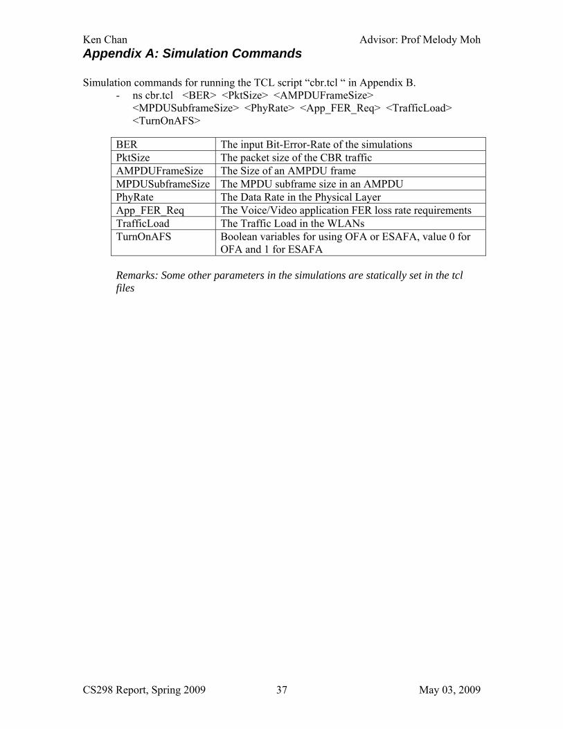
Appendix A: Simulation Commands Simulation commands for running the TCL script “cbr.tcl “ in Appendix B.
- ns cbr.tcl <BER> <PktSize> <AMPDUFrameSize> <MPDUSubframeSize> <PhyRate> <App_FER_Req> <TrafficLoad> <TurnOnAFS>
BER The input Bit-Error-Rate of the simulations PktSize The packet size of the CBR traffic AMPDUFrameSize The Size of an AMPDU frame MPDUSubframeSize The MPDU subframe size in an AMPDU PhyRate The Data Rate in the Physical Layer App_FER_Req The Voice/Video application FER loss rate requirements TrafficLoad The Traffic Load in the WLANs TurnOnAFS Boolean variables for using OFA or ESAFA, value 0 for
OFA and 1 for ESAFA Remarks: Some other parameters in the simulations are statically set in the tcl files

Ken Chan Advisor: Prof Melody Moh
CS298 Report, Spring 2009 May 03, 2009 38
Appendix B: TCL Scripts for Simulation We have done the simulation by using the TCL scripts. Comments are provided for description of parts of the script.
- the cbr_default_options.tcl defines the default options for simulating cbr performance on WLAN.
# ====================================================================== # Define options # ====================================================================== set val(chan) Channel/WirelessChannel ;# channel type set val(prop) Propagation/TwoRayGround ;# radio-propagation model set val(netif) Phy/WirelessPhy ;# network interface type set val(mac) Mac/802_11 ;# MAC type set val(ifq) Queue/DropTail/PriQueue ;# interface queue type set val(ll) LL ;# link layer type set val(ant) Antenna/OmniAntenna ;# antenna model set val(rp) DumbAgent ;# routing protocol set val(start) 0.0 set val(tr) "trace" set val(X) 100 set val(Y) 100 set val(UPDpacketsize) 65536 set val(RTSThreshold) 65536 set val(ShortRetryLimit) 4 set val(LongRetryLimit) 4 set val(CWmin) 16 set val(CWmax) 1024 set val(SlotTime) 0.000009 set val(SIFS) 0.000016 set rng [new RNG] $rng seed 0 set ss [$rng next-random] #puts "random number for ns is: $ss" set opt(seed) $ss
- the cbr_scenario.tcl defines the traffic flows and the stations’ positions # Get default options source phyrate_cbr-default_options.tcl

Ken Chan Advisor: Prof Melody Moh
CS298 Report, Spring 2009 May 03, 2009 39
# Station position #puts "---------------------------------------------------------------------" for {set i 1} {$i < $val(nn)+1 } {incr i 1} { $node_([expr $i-1]) set X_ [expr $val(X)-$i] $node_([expr $i-1]) set Y_ [expr $val(Y)-$i] $node_([expr $i-1]) set Z_ 0.0 } #puts "---------------------------------------------------------------------" # Flow from this station to all the others #puts "---------------------------------------------------------------------" set flowid 0 # only one flow # set i 0 # set udp($flowid) [new Agent/UDP] # set null($flowid) [new Agent/Null] # $ns_ attach-agent $node_($i) $udp($flowid) # $ns_ attach-agent $node_([expr ($i+1) % $val(nn)]) $null($flowid) # $ns_ connect $udp($flowid) $null($flowid) # set cbr($flowid) [new Application/Traffic/CBR] # $cbr($flowid) attach-agent $udp($flowid) # # $ns_ at [expr $val(start)+[expr $i / 1000]] "$cbr($flowid) start" # $ns_ at [expr $val(start)+ $i]] "$cbr($flowid) start" # set flowid [expr $flowid + 1] # multi flows for {set i 0} {$i < $val(nn) } {incr i 1} { set udp($flowid) [new Agent/UDP] set null($flowid) [new Agent/Null] $ns_ attach-agent $node_($i) $udp($flowid) $ns_ attach-agent $node_([expr ($i+1) % $val(nn)]) $null($flowid) $ns_ connect $udp($flowid) $null($flowid) set cbr($flowid) [new Application/Traffic/CBR] $cbr($flowid) attach-agent $udp($flowid) # $ns_ at [expr $val(start)+[expr $i / 1000]] "$cbr($flowid) start" # $ns_ at [expr $val(start)+ $i]] "$cbr($flowid) start" $ns_ at $val(start) "$cbr($flowid) start" set flowid [expr $flowid + 1] } #puts "---------------------------------------------------------------------"
- the cbr.tcl defines the core of the cbr simulations and the record of nam graph and .tr trace file, following are parts of the files and explanations

Ken Chan Advisor: Prof Melody Moh
CS298 Report, Spring 2009 May 03, 2009 40
# ====================================================================== # Define options # ====================================================================== source phyrate_cbr-default_options.tcl #---------------------------------------------------------------------------- set val(nn) 10 ;##fixed node number for testing CBR traffic set val(ifqlen) 10 ;# max packet in ifq set val(Sq_LIMIT) 10 set val(run) 5.0 #----------------------------------------------------------------------- set val(BER) [lindex $argv 0] set val(PktSize) [lindex $argv 1] set val(FRAMELEN) [lindex $argv 2] set val(fgLEN) [lindex $argv 3] set val(DELAY) 0.0 ;# duration of delay timer, change to 0.0 instead of using argument 4 set val(temp) [lindex $argv 4] ;# datarate set val(appFERReq) [lindex $argv 5] set val(trafficload) [lindex $argv 6] set val(turnOnAFS) [lindex $argv 7] set val(dataRate) $val(temp)Mb set val(basicRate) 6.0Mb ;#changed to 6.0MB set val(CBRrate) [expr $val(temp)/$val(nn)*$val(trafficload)]Mb puts "CBRrate for each station = $val(CBRrate)" #----------------------------------------------------------------------- set val(percentage) 0.03 ;#for calculating the percentage with more than 30ms set val(OrigPktSize) [lindex $argv 1] #---------------------------------------------------------------------------- Mac/802_11 set fgLEN_ $val(fgLEN) Mac/802_11 set BER_ $val(BER) Mac/802_11 set Sq_LIMIT_ $val(Sq_LIMIT) ;# number of fragments Mac/802_11 set peakDelay_ 0.0 Mac/802_11 set percentage_ $val(percentage) Mac/802_11 set appFERReq_ $val(appFERReq) ;#for setting applicationFERRequirement #Mac/802_11 set PLCPDataRate_ $val(PLCPRate) set val(avoidARP) 0.0 set val(stop) [expr $val(start)+$val(avoidARP)+$val(run)] #--------------------------------------------------------------------------------

Ken Chan Advisor: Prof Melody Moh
CS298 Report, Spring 2009 May 03, 2009 41
puts "----------------------------------------------------------------" puts "BER PktSize AMPDU_Frame_Size AMSDU_Frame_Size DataRate(Mbps) App_FER_Req Trafficload TurnOnAFS" puts "$val(BER) $val(PktSize) $val(FRAMELEN) $val(fgLEN) $val(dataRate) $val(appFERReq) $val(trafficload) $val(turnOnAFS)" puts "----------------------------------------------------------------" #-------------------------------------------------------------------------------- # PHY MIB #-------------------------------------------------------------------------------- Phy/WirelessPhy set CPThresh_ 20000.0 ;#capture threshold (db) Phy/WirelessPhy set Pt_ 0.2818 ;#for 250m range #-------------------------------------------------------------------------------- # MAC MIB #-------------------------------------------------------------------------------- Mac/802_11 set PktSize_ $val(PktSize) Mac/802_11 set basicRate_ $val(basicRate) Mac/802_11 set dataRate_ $val(dataRate) Mac/802_11 set CWMin_ $val(CWmin) Mac/802_11 set CWMax_ $val(CWmax) Mac/802_11 set SlotTime_ $val(SlotTime) Mac/802_11 set SIFS_ $val(SIFS) Mac/802_11 set RTSThreshold_ $val(RTSThreshold) Mac/802_11 set ShortRetryLimit_ $val(ShortRetryLimit) Mac/802_11 set LongRetryLimit_ $val(LongRetryLimit) Mac/802_11 set STANUM_ $val(nn) Mac/802_11 set THRind_ 0.0 Mac/802_11 set SizeOfAllFrame_ 0 Mac/802_11 set totalDelay_ 0.0 Mac/802_11 set percentageDelay_ 0.0 Mac/802_11 set recvNumber_ 0 Mac/802_11 set DELAY_ $val(DELAY) Mac/802_11 set FRAMELEN_ $val(FRAMELEN) Mac/802_11 set turnOnAFS_ $val(turnOnAFS) #-------------------------------------------------------------------------------- # Antenna settings #-------------------------------------------------------------------------------- # unity gain, omni-directional antennas # set up the antennas to be centered in the node and 1.5 meters above it Antenna/OmniAntenna set X_ 1 Antenna/OmniAntenna set Y_ 1 Antenna/OmniAntenna set Z_ 1.5 Antenna/OmniAntenna set Gt_ 1.0 Antenna/OmniAntenna set Gr_ 1.0

Ken Chan Advisor: Prof Melody Moh
CS298 Report, Spring 2009 May 03, 2009 42
# Application Characteristics Agent/CBR set sport_ 0 Agent/CBR set dport_ 0 Application/Traffic/CBR set rate_ $val(CBRrate) Application/Traffic/CBR set packetSize_ $val(PktSize) ;#bytes Agent/UDP set packetSize_ $val(UPDpacketsize) ;#bytes Agent/Null set sport_ 0 Agent/Null set dport_ 0 # LL LL set mindelay_ 0us LL set delay_ 0us LL set bandwidth_ 0 ;# not used LL set off_prune_ 0 ;# not used LL set off_CtrMcast_ 0 ;# not used LL set debug_ false # ====================================================================== # Global Procedures # ====================================================================== #remove-all-packet-headers #remove-packet-header AODV ARP IMEP IPinIP IVS LDP MPLS MIP Ping PGM PGM_SPM PGM_NAK NV Smac Pushback TORA TFRC_ACK TFRC ;# original remove-packet-header IMEP IPinIP IVS LDP MPLS MIP Ping PGM PGM_SPM PGM_NAK NV Smac Pushback TORA TFRC_ACK TFRC #add-packet-header Common IP Mac TCP LL CtrMcast # new ns #------------------------------------------------------------------------ set ns_ [new Simulator] $ns_ use-newtrace ;# change to use another trace # CMU trace format, trace if needed set tracefd [open $val(tr).cmu.all w] $ns_ trace-all $tracefd puts "second times" proc hello {} { puts "hello" } # open the tr trace file and the nam graph

Ken Chan Advisor: Prof Melody Moh
CS298 Report, Spring 2009 May 03, 2009 43
#set f [open final_out.tr w] #$ns trace-all $f ## set nam trace for graph generation ##/////enable namtrace if needed #set namtrace [open phyrate_cbr.nam w] #$ns_ namtrace-all-wireless $namtrace $val(X) $val(Y) #set f0 [open bandwidth_node1.tr w] #set f1 [open npkts_node1.tr w] ## open throughput, average delay and peak delay and fairness or percentage delay if needed here #set f_throughput [open throughput_dcf.tr w] #set f_averagedelay [open averagedelay__dcf.tr w] #set f_peakdelay [open peakdelay_dcf.tr w] #set f_data [open phyrate_cbr_data_$val(temp).tr a] ns-random 0 ;# may not be useful # set up topography object set topo [new Topography] $topo load_flatgrid $val(X) $val(Y) # Create God create-god $val(nn) ## need to get the wireless channel value first #set wirelesschan [new $val(chan)] #------------------------------------------------------------------------ $ns_ node-config -adhocRouting $val(rp) \ -llType $val(ll) \ -macType $val(mac) \ -ifqType $val(ifq) \ -ifqLen $val(ifqlen) \ -antType $val(ant) \ -propType $val(prop) \ -phyType $val(netif) \ -channelType $val(chan) \ -topoInstance $topo \ -agentTrace ON \ -routerTrace ON \ -macTrace ON \ -movementTrace ON # -channel $val(chan) ;# wireless channel # -agentTrace OFF \ ;# should be set to ON for nam trace

Ken Chan Advisor: Prof Melody Moh
CS298 Report, Spring 2009 May 03, 2009 44
# -routerTrace OFF \ # -macTrace OFF \ # -movementTrace OFF #------------------------------------------------------------------------ ##Need to do sth here ......... # Create node #------------------------------------------------------------------------ for {set i 0} {$i < $val(nn) } {incr i} { # assign dst address in TCL because I do not use ARP pkts LL set macDA_ [expr [expr $i+1] % $val(nn)] LL set dataDA_ [expr [expr $i+1] % $val(nn)] if { $i == 0 } { LL set tcpAckDA_ [expr $val(nn) - 1 ] } else { LL set tcpAckDA_ [expr $i-1] } set node_($i) [$ns_ node] $node_($i) random-motion 0 ;# disable random motion $ns_ initial_node_pos $node_($i) 30 ;# define the initial position of nodes........must be called after mobility model has defined. #$node_($i) set SlotTime_ } #--------------------------------------------------------------------- source phyrate_cbr-scenario.tcl # Station position # Station position #set phydatarate $var(dataRate) #put "$var(dataRate)" ###for setting the first line proc stop {} { global ns_ val node_ temp_delay tracefd f_data #namtrace #f_throughput f_averagedelay f_peakdelay $ns_ flush-trace ; #flush the trace file #exec xgraph cwnd_tcp1.tr #exec xgraph pkt_received_at_node1.tr set sum 0.0 set squaresum 0.0 set peakDelay 0.0 #set f_throughput [open "phyrate_cbr_throughput_ampdu.tr" "a"]

Ken Chan Advisor: Prof Melody Moh
CS298 Report, Spring 2009 May 03, 2009 45
#set f_a_delay [open "phyrate_cbr_average_delay_ampdu.tr" "a"] #set f_p_delay [open "phyrate_cbr_peak_delay_ampdu.tr" "a"] #set f_fairness [open "phyrate_cbr_fairness_ampdu.tr" "a"] #set f_percentage_delay [open "phyrate_cbr_percentage_delay_ampdu.tr" "a"] # omit BER and TrafficLoad, put $val(dataRate) in the front of file, to get result for BER and TL #$val(BER) $val(PktSize) $val(FRAMELEN) $val(fgLEN) $val(dataRate) $val(appFERReq) $val(trafficload) $val(turnOnAFS) #set f_data [open phyrate_cbr_data_$val(dataRate)_$val(PktSize)_$val(FRAMELEN)_$val(fgLEN)_$val(appFERReq)_$val(turnOnAFS).tr a] set f_data [open phyrate_cbr_data_Optimal_vs_Adaptive.tr a] #set f_data [open phyrate_cbr_data_BER_vs_AMSDUSize.tr a] #set f_data [open phyrate_cbr_data_test.tr a] for {set i 0} {$i < $val(nn) } {incr i} { set mac [$node_($i) getMac 0] ;## get the current mac instance set throughput($i) [$mac set THRind_] set totalDelay [$mac set totalDelay_] set recvNumber [$mac set recvNumber_] set temp_delay [$mac set peakDelay_] set totalBER [$mac set totalBER_] ;## for caluculating actual BER increase with TL set totalBERCounter [$mac set totalBERCounter_] set averageActualFER [$mac set averageActualFER_] set averageActualBER [$mac set averageActualBER_] set peakDelay [expr $peakDelay + $temp_delay] set percentageDelay [$mac set percentageDelay_] ;## for caluculating percentage delay, percentage is set to MAC previously set numExceed30ms [$mac set numExceed30ms_] #puts "peak Delay=$temp_delay" set sum [expr $sum + $throughput($i)] set squaresum [expr $squaresum+[expr $throughput($i)*$throughput($i)]] } ##need to move forward set nominator [expr $sum*$sum] set denominator [expr $val(nn)*$squaresum] set fairness [expr $nominator/$denominator] ##for tracing performance in .tr file set systhroughput [expr $sum/$val(stop)] set a_delay [expr $totalDelay/$recvNumber] set a_actual_BER [expr $totalBER/$totalBERCounter] ;## for calculating the average actual BER. set p_delay [expr $peakDelay/$val(nn)] set percentageDelay [expr $percentageDelay]
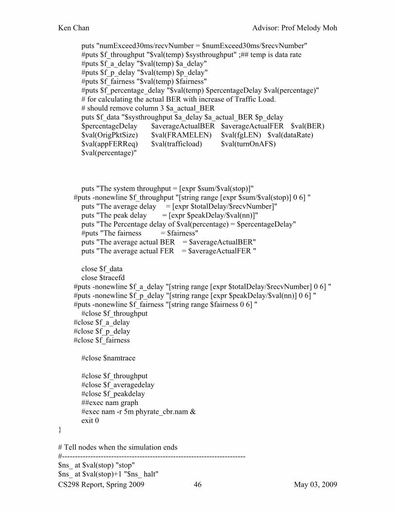
Ken Chan Advisor: Prof Melody Moh
CS298 Report, Spring 2009 May 03, 2009 46
puts "numExceed30ms/recvNumber = $numExceed30ms/$recvNumber" #puts $f_throughput "$val(temp) $systhroughput" ;## temp is data rate #puts $f_a_delay "$val(temp) $a_delay" #puts $f_p_delay "$val(temp) $p_delay" #puts $f_fairness "$val(temp) $fairness" #puts $f_percentage_delay "$val(temp) $percentageDelay $val(percentage)" # for calculating the actual BER with increase of Traffic Load. # should remove column 3 $a_actual_BER puts $f_data "$systhroughput $a_delay $a_actual_BER $p_delay $percentageDelay $averageActualBER $averageActualFER $val(BER) $val(OrigPktSize) $val(FRAMELEN) $val(fgLEN) $val(dataRate) $val(appFERReq) $val(trafficload) $val(turnOnAFS) $val(percentage)" puts "The system throughput = [expr $sum/$val(stop)]" #puts -nonewline $f_throughput "[string range [expr $sum/$val(stop)] 0 6] " puts "The average delay = [expr $totalDelay/$recvNumber]" puts "The peak delay = [expr $peakDelay/$val(nn)]" puts "The Percentage delay of $val(percentage) = $percentageDelay" #puts "The fairness = $fairness" puts "The average actual BER = $averageActualBER" puts "The average actual FER = $averageActualFER " close $f_data close $tracefd #puts -nonewline $f_a_delay "[string range [expr $totalDelay/$recvNumber] 0 6] " #puts -nonewline $f_p_delay "[string range [expr $peakDelay/$val(nn)] 0 6] " #puts -nonewline $f_fairness "[string range $fairness 0 6] " #close $f_throughput #close $f_a_delay #close $f_p_delay #close $f_fairness #close $namtrace #close $f_throughput #close $f_averagedelay #close $f_peakdelay ##exec nam graph #exec nam -r 5m phyrate_cbr.nam & exit 0 } # Tell nodes when the simulation ends #----------------------------------------------------------------------- $ns_ at $val(stop) "stop" $ns_ at $val(stop)+1 "$ns_ halt"
Ken Chan Advisor: Prof Melody Moh
CS298 Report, Spring 2009 May 03, 2009 47
# Run ns... #----------------------------------------------------------------------- $ns_ run

Ken Chan Advisor: Prof Melody Moh
CS298 Report, Spring 2009 May 03, 2009 48
Appendix C: TCL File for Batch Simulation Run
- The tcl script file cbr_run.tcl defines the parameters for generating multiple run on cbr.tcl
#################################################################### # init variable lists #################################################################### set BER {0.000001 0.00001 0.00002 0.00005 0.0001} #set BER {0.000001} #set BER {0.000001 0.000005 0.00001 0.00005 0.0001} set PktSize {1024} set Frame {65535} set Frag {8192} ;# PKT = Frag set phyrate {144} set App_FER_Req {0.10} set TrafficLoad {0.5} #set TrafficLoad {1.0} #0.3 0.5 0.7 1.0 set turnOnAFS {0 1} set on_off 1 ;#on of off AFS #set x_axis $phyrate #set DelayTimer {0.0} #set PKT {1024, 2048, 4095, 6142, 8190} #set phyrate {54 108 162 216 270 324 378 432} puts "----------------------------------------------------------------" puts "BER PktSize AMPDU_Frame_Size AMSDU_Frame_Size DataRate(Mbps) App_FER_Req Trafficload TurnOnAFS" puts "$BER $PktSize $Frame $Frag $phyrate $App_FER_Req $TrafficLoad $turnOnAFS" puts "----------------------------------------------------------------" #set f_data [open phyrate_cbr_data_$phyrate.tr a] #puts $f_data "BER PktSize AMPDU_Frame_Size AMSDU_Frame_Size DataRate(Mbps) App_FER_Req Trafficload TurnOnAFS" # ns phyrate_cbr.tcl BER, PktSize, FrameLen, fgLen, Delay, DataRate, TrafficLoad" #for {set k 0} {$k < [llength $phyrate] } {incr k} { #for {set j 0} {$j < [llength $App_FER_Req] } {incr j} { for {set i 0} {$i < [llength $BER] } {incr i} { puts "Executing ns phyrate_cbr.tcl [lindex $BER $i] [lindex $PktSize 0] [lindex $Frame 0] [lindex $Frag 0] [lindex $phyrate 0] [lindex $App_FER_Req $j] [lindex $TrafficLoad 0] [lindex $turnOnAFS $on_off]"
Ken Chan Advisor: Prof Melody Moh
CS298 Report, Spring 2009 May 03, 2009 49
exec ns phyrate_cbr.tcl [lindex $BER $i] [lindex $PktSize 0] [lindex $Frame 0] [lindex $Frag 0] [lindex $phyrate 0] [lindex $App_FER_Req $j] [lindex $TrafficLoad 0] [lindex $turnOnAFS $on_off] >> "auto-result-ampdu.txt" 2> /dev/null # we must put ">> "auto-result-ampdu.txt" 2> /dev/null", if not the CLI crash } } }