evaporation heat transfer coefficients of ammonia with a ... heat transfer coefficients of the...
TRANSCRIPT
Evaporation heat transfer coefficients of ammonia with a small
content of water in a plate heat exchanger in an absorption
refrigeration machine
Igor Ventura
Under supervision of Prof. Filipe Mendes
Dep. Physics, IST, Lisbon, Portugal
December 6, 2010
Abstract
Evaporation heat transfer coefficients of the mixture ammonia-water in a plate heat exchanger
(PHE) are investigated experimentally in this study. The study is performed in the evaporator of an
absorption refrigeration machine prototype at LSAS. During experiments to characterize the prototype,
data on the evaporator was collected for this study. In the evaporator, the refrigerant is cooled with
water and both fluids circule in counterflow. The experimental parameters in this work include the
refrigerant mass flux with a range from 0,90 to 3,09 kgm−2s−1, heat flux from 616,6 to 2962 W/m2
,
pressure from 3,75 to 6,54 bar and ammonia concentration from 0,93 to 0,99. Correlations proposed
on literature for heat transfer coefficients for evaporation in PHEs doesn’t fit to our data. A correction
for those correlations were proposed based on the fact that the ammonia concentration of the mixture
influences the calculation of heat transfer coefficients.
Keywords: Evaporation; Plate heat exchanger; Heat transfer coefficient; Correla-
tion; Absorption; Ammonia-water; Experiment
1 Introduction
Plate heat exchangers (PHE) have been used since
1930’s in chemical and food processing industries
for single-phase heat transfer from liquid-to-liquid.
In the 70’s they also began to be used in heat trans-
fer processes with phase changing, particularly con-
densers and evaporators in chillers and heat pumps.
1

The use of PHE in refrigeration machines as be-
come more common due to their compactness, heat
transfer area, the facility to create and maintain a
turbulent flow and higher heat transfer coefficients
when compared with other usual heat exchangers.
In the last years, developed countries start to
making some efforts to reduce the energy consump-
tion and carbon dioxide emissions to the atmo-
sphere. In this context, absorption refrigeration
machines powered by solar energy can be seen as a
promising technology as a replacement of conven-
tional air-conditioning systems which represents an
important section of total electric energy consump-
tion in the world.
The work present in this paper fits the develop-
ment of an air-cooled absorption refrigeration ma-
chine prototype of small power at Laboratório de
Sistemas de Arrefécimento Solar (LSAS). This pro-
totype were built to have a refrigeration power of
5kW with a COP of 0,56. The working fluid used
were an ammonia-water mixture.
Particularly, this work study the heat transfer
process in the evaporator . The evaporation pro-
cess in a refrigeration machine is very important on
its performance.
The evaporator is the machine’s component
that receive heat from the environment we pretend
to cool and it is extremely important that its de-
sign fit in the cooling power capacity of the ma-
chine. The heat exchanger used as evaporator on
the prototype is a PHE.
Many studies that have been perform to the
PHEs can be found in open literature. However,
most of them are focused in single-phase heat trans-
fer from liquid-to-liquid, especially for water [1].
Only in the last two decades some work has been
published about two-phase heat transfer on this
exchangers type and therefore, there are limited
data available to the use of PHEs in processes with
phase-changing like evaporation.
Recently, Y.Y Yan and T.F. Lin, D. Donowski
and S.G. Kandlikar, Y.Y. Hsieh and T.F. Lin and
Han and Kim had proposed correlations for heat
transfer coefficients during the evaporation of re-
frigerants in a PHE [2, 3, 4, 5]. Some other
authors had studied evaporation process in PHE
[6, 7, 8, 9, 10, 11].
However the only available work on ammonia-
water mixture evaporation in a PHE was done by
F. Táboas who study the forced boiling of the mix-
ture in a PHE [12, 13].
There are no works where the study of heat
transfer coefficients are done with mixtures with
different concentrations of the refrigeran. In this
work, we try to correlate our data to a heat trans-
fer coefficient correlation and evaluate the influence
of ammonia concentration in the heat transfer cor-
relations.
2
2 Experimental set-up and proce-
dure
2.1 System description
This experiment wasn’t dedicated to the study of
ammonia-water evaporation in a PHE. All data col-
lected for this study were measured while testing
the operating conditions of the absorption refriger-
ation machine prototype.
The prototype studied is a single stage
ammonia-water chiller with plate heat exchangers
using water to the heat transfer at the main compo-
nents. The water from the Absorber and Condenser
is air-cooled. There are to boilers to simulate the
water from the solar panels and the charge. The
machine have two internal heat recovery heat ex-
changers as it is usual in this kind of absorption
cycles. The Generator is coupled with a separation
vessel. Also two refining devices were used dur-
ing the experiments. Those were coupled with the
generator vessel and were tested by working with
a contraflow between the vapor generated and the
rich solution.
At the first column an aerosol is created by
a nozzle to promote the mass and heat exchange.
The second column is random packed with Novalox
ceramic saddles.
The beginning of the experiments on the proto-
type were done without any refining system incor-
porated.
All the system were thermally isolated.
During the experiments on the prototype sev-
eral experimental conditions were tested and all the
external inputs were changed: the water flow rates
and temperatures at generator, absorver, condenser
and evaporator; the rich solution and refrigerant
flow rate through the expansion valve.
The amount of ammonia at the solution circuit
was also changed retaining it in the refrigeration
circuit.
The variation of external inputs during the ex-
periments and the use of different systems to treat
vapor produced at the generator (refining columns)
changed the concentration of the mixture. There-
fore, data points obtained for the study of heat
transfer at the evaporator have different values of
ammonia concentration on the mixture.
2.2 Plate heat exchanger
The heat exchanger used as evaporator on the pro-
totype is a nickel brazed plate heat exchanger,
model NB-26-18H manufactured by Alfa Laval.
This heat exchanger have 18 plates forming 17chan-
nels where 9 are intend for water flow and 8 for the
ammonia-water mixture.
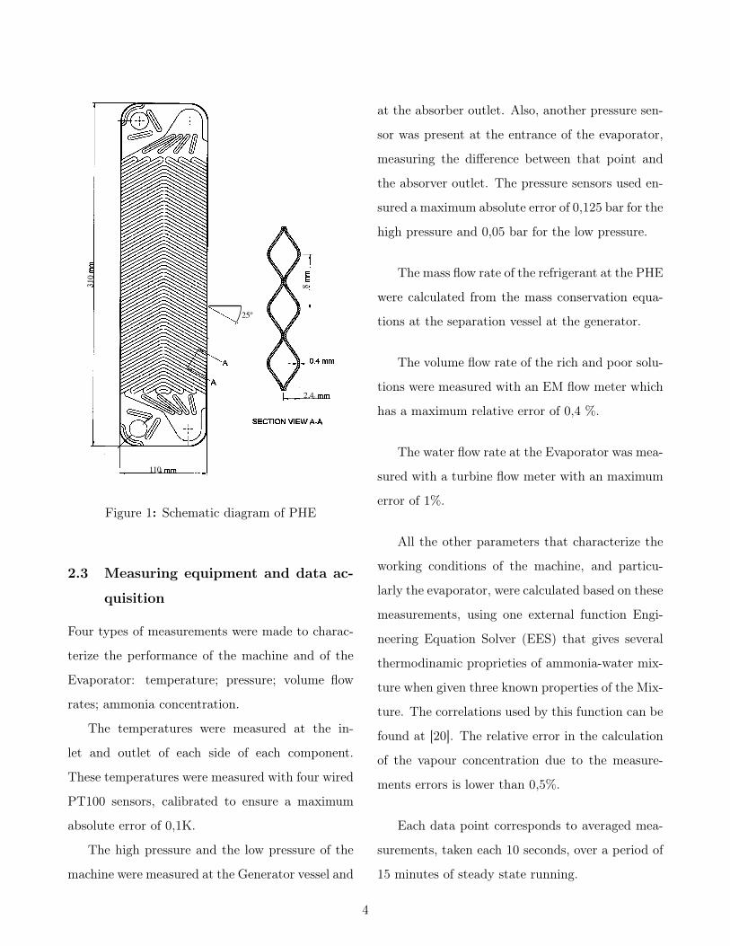
The plates of the PHE have a herringbone cor-
rugation type with a chevron angle of 25%.
The water side and refrigerant side on the PHE
circulate in counterflow.
Figure 1 shows a schematic of the PHE geomet-
ric characteristics
3
!"#$%&'("&))* !#+,- (- .(/0 12 "+-!(!'! +3 3+45 (-6$78$-6$-' )++8! &-6 & 6&'& &"94(!('(+- !*!'$%0 :' (-")46$!& 5$35(/$5&-' )++82 ',+ ,&'$5 )++8! ;+-$ 3+5 85$#$&'$5&-6 '#$ &-+'#$5 3+5 '#$ '$!' !$"'(+-<2 &-6 & "+)6 ,&'$5=/)*"+) )++80 :- +56$5 '+ "+-'5+) >&5(+4! '$!' "+-6('(+-!+3 ?7@1AB ;(-")46(-/ (%8+!$6 #$&' C4D2 5$35(/$5&-'%&!! C4D &-6 !*!'$% 85$!!45$< (- '#$ '$!' !$"'(+-2 ,$-$$6 '+ "+-'5+) '#$ '$%8$5&'45$ &-6 C+, 5&'$ (- '#$+'#$5 '#5$$ )++8!0
!"#" $%&'()%'*+, -./ 0..1
E#$ 5$35(/$5&-' )++8 "+-'&(-! & >&5(&F)$7!8$$6 5$735(/$5&-' 84%8 '#&' 6$)(>$5! '#$ !4F"++)$6 5$35(/$5&-' '+& 85$#$&'$50 E#$ 5$35(/$5&-' %&!! C+, 5&'$ (! %&(-)*"+-'5+))$6 F* &- BG %+'+5 '#5+4/# '#$ "#&-/$ +3 '#$(->$5'$5 35$94$-"*0 E#$ C+, 5&'$ "&- F$ 345'#$5 &6H4!'$6F* 5$/4)&'(-/ '#$ F*8&!! >&)>$ (- '#$ C+, 8&'# 35+% '#$5$35(/$5&-' 84%80 E+ %$&!45$ '#$ 5$35(/$5&-' %&!! C+,5&'$2 &- &""45&'$ %&!! C4D %$'$5 (! (-!'&))$6 F$',$$- '#$5$35(/$5&-' 84%8 &-6 85$#$&'$5 ,('# & 5$&6(-/ &""45&"*+3 !1I0 E#$ !4F"++)$6 5$35(/$5&-' )(94(6 (! #$&'$6 (- '#$85$#$&'$5 '+ & 85$!"5(F$6 !&'45&'$6 !'&'$ F$3+5$ $-'$5(-/'#$ '$!' !$"'(+-0 E#$-2 '#$ !&'45&'$6 )(94(6 5$35(/$5&-'%+>$! (-'+ '#$ '$!' !$"'(+- &-6 ?7@1AB F+()! '#$5$0 .(7-&))*2 '#$ >&8+5=)(94(6 5$35(/$5&-' %(D'45$ (! "+-6$-!$6&-6 !4F"++)$6 F* '#$ )+,7'$%8$5&'45$ ,&'$5=/)*"+) (-'#$ !#$))7&-67"+() #$&' $D"#&-/$5! &"'(-/ &! "+-6$-!$5&-6 !4F"++)$50 B- &""4%4)&'+5 (! "+--$"'$6 '+ & #(/#785$!!45$ -('5+/$- '&-J '+ 6&%8$- '#$ C4"'4&'(+-! +3 '#$C+, 5&'$ &-6 85$!!45$0 :- &66('(+-2 '#$ )++8 (! &)!+$94(88$6 ,('# & 5$"$(>$52 & K)'$5L65*$52 & 5$)$&!$ >&)>$2 &6$/&!!$6 >&)>$ &-6 3+45 !(/#' /)&!!$!0 E#$ 85$!!45$ +3 '#$5$35(/$5&-' )++8 "&- F$ "+-'5+))$6 F* >&5*(-/ '#$ '$%78$5&'45$ &-6 C+, 5&'$ +3 '#$ ,&'$5=/)*"+) (- '#$ "+-76$-!$5 &-6 !4F"++)$50 E,+ &F!+)4'$ 85$!!45$'5&-!64"$5! &5$ (-!'&))$6 &' '#$ (-)$' &-6 $D(' +3 '#$ '$!'!$"'(+- ,('# 5$!+)4'(+- 48 '+ !M JN&0 .45'#$5%+5$2 &"&)(F5&'$6 6(O$5$-'(&) 85$!!45$ '5&-!64"$5 (! 4!$6 '+%$&!45$ '#$ +>$5&)) 85$!!45$ 65+8 &"5+!! '#$ 5$35(/$5&-'!(6$ +3 '#$ >$5'("&) NPQ0 B)) '#$ ,&'$5 &-6 5$35(/$5&-''$%8$5&'45$! &5$ %$&!45$6 F* '*8$ E "+88$5="+-!'&-'&-'#$5%+"+48)$! ,('# & "&)(F5&'$6 &""45&"* +3 !A0M !G0 BR "% '#("J 8+)*$'#*)$-$ (-!4)&'(+- (! ,5&88$6 &5+4-6'#$ ,#+)$ )++8 '+ 5$64"$ '#$ #$&' )+!! '+ '#$ &%F($-'0
!"!" 234
E#5$$ "+%%$5"(&) SS7T1U 8)&'$! %&-43&"'45$6 F* '#$V&+5( P$&' E5$&'%$-'2 E&(,&- 3+5% '#$ NPQ 3+5 '#$!&'45&'$6 C+, F+()(-/ '$!'0 E#$ 8)&'$ !453&"$! &5$85$!!$6 '+ F$"+%$ /5++>$6 ,('# & "+554/&'$6 !(-4!+(6&)!#&8$ &-6 UA! +3 "#$>5+- &-/)$2 ,#("# (! '#$ &-/)$ +3 W7/5++>$! '+ '#$ >$5'("&) &D(! +3 '#$ 8)&'$0 E#$ 6$'&()$6"+-K/45&'(+- 3+5 '#$ NPQ "&- F$ !$$- (- .(/0 M0 E#$"+554/&'$6 /5++>$! +- '#$ 5(/#' &-6 )$3' +4'$5 8)&'$!
#&>$ & W !#&8$ F4' '#+!$ (- '#$ %(66)$ 8)&'$ #&>$ &"+-'5&5* W !#&8$ +- F+'# !(6$!0 E#(! &55&-/$%$-' &)7)+,! '#$ C+, !'5$&% '+ F$ 6(>(6$6 (-'+ ',+ 6(O$5$-' C+,6(5$"'(+-! &)+-/ '#$ 8)&'$!0 E#4!2 '#$ C+, %+>$! %&(-)*&)+-/ '#$ /5++>$! (- $&"# 8)&'$0 X4$ '+ '#$ "+-'5&5* W!#&8$! F$',$$- ',+ -$(/#F+5 8)&'$! '#$ C+, !'5$&%!-$&5 '#$ ',+ 8)&'$! "5+!! $&"# +'#$5 (- $&"# "#&--$)0E#(! "5+!! C+, 5$!4)'! (- !(/-(K"&-' C+, 4-!'$&6(-$!!&-6 5&-6+%-$!!0 :- 3&"'2 '#$ C+, (! #(/#)* '45F4)$-'$>$- ,#$- '#$ ?$*-+)6! -4%F$5 (! )+,0 :- '#$ NPQ'#5$$ 8)&'$! 3+5% ',+ >$5'("&) "+4-'$5 C+, "#&--$)!0Y8C+, +3 '#$ !&'45&'$6 5$35(/$5&-' ?7@1AB (- +-$"#&--$) (! #$&'$6 F* '#$ 6+,-C+, +3 '#$ #+' ,&'$5 (-'#$ +'#$5 "#&--$)0 E#$ #$&' '5&-!3$5 5&'$ (- '#$ '$!'!$"'(+- (! "&)"4)&'$6 F* %$&!45(-/ '#$ ,&'$5 '$%8$5&'45$65+8 F$',$$- '#$ ,&'$5 "#&--$) (-)$' &-6 +4')$' &-6 '#$,&'$5 C+, 5&'$0
!"5" 6*,%' 0..1 &.' ,%7, 7%8,(.+
E#$ ,&'$5 )++8 (- '#$ $D8$5(%$-'&) !*!'$% 3+5 "(57"4)&'(-/ '#$ #+' ,&'$5 '#5+4/# '#$ '$!' !$"'(+- "+-'&(-! &MA ) ,&'$5 '#$5%+!'&' ,('# & A0R JZ #$&'$52 &-6 & ,&'$584%8 (! 4!$6 '+ 65(>$ '#$ #+' ,&'$5 &' & !8$"(K$6 ,&'$5
.(/0 M0 S"#$%&'(" 6(&/5&% +3 NPQ0
1ATU 9"9" 37(%:; <"=" >(+ ? @+,%'+*,(.+*0 A.B'+*0 .& 3%*, *+C D*77 <'*+7&%' EF G!HH!I #H55J#HEE
Figure 1: Schematic diagram of PHE
2.3 Measuring equipment and data ac-
quisition
Four types of measurements were made to charac-
terize the performance of the machine and of the
Evaporator: temperature; pressure; volume flow
rates; ammonia concentration.
The temperatures were measured at the in-
let and outlet of each side of each component.
These temperatures were measured with four wired
PT100 sensors, calibrated to ensure a maximum
absolute error of 0,1K.
The high pressure and the low pressure of the
machine were measured at the Generator vessel and
at the absorber outlet. Also, another pressure sen-
sor was present at the entrance of the evaporator,
measuring the difference between that point and
the absorver outlet. The pressure sensors used en-
sured a maximum absolute error of 0,125 bar for the
high pressure and 0,05 bar for the low pressure.
The mass flow rate of the refrigerant at the PHE
were calculated from the mass conservation equa-
tions at the separation vessel at the generator.
The volume flow rate of the rich and poor solu-
tions were measured with an EM flow meter which
has a maximum relative error of 0,4 %.
The water flow rate at the Evaporator was mea-
sured with a turbine flow meter with an maximum
error of 1%.
All the other parameters that characterize the
working conditions of the machine, and particu-
larly the evaporator, were calculated based on these
measurements, using one external function Engi-
neering Equation Solver (EES) that gives several
thermodinamic proprieties of ammonia-water mix-
ture when given three known properties of the Mix-
ture. The correlations used by this function can be
found at [20]. The relative error in the calculation
of the vapour concentration due to the measure-
ments errors is lower than 0,5%.
Each data point corresponds to averaged mea-
surements, taken each 10 seconds, over a period of
15 minutes of steady state running.
4

3 Data reduction
In order to proceed with calculations of heat trans-
fer coefficients of ammonia-water mixture from the
experimental data some data reduction analysis is
needed.
Shah and Wanniarachchi [17] suggested that
the hydraulic diameter of the PHE channels can
be expressed as two times the mean channel spac-
ing if the channel width is much larger than the
channel spacing,
De = 2 b (1)
The overall heat transfer coefficient in the evap-
orator, U , can be expressed as
U =Q
A∆Tln(2)
where Q is the heat transfer rate from the hot
fluid to the refrigerant, A is the heat transfer area
of the PHE and ∆Tln is the logarithmic mean tem-
perature difference which can be calculated by the
expression
∆Tln =�Tin −�Tout
ln�
�Tin�Tout
� (3)
with
�Tin = Tw, in − Tr, out (4)
�Tout = Tw, out − Tr, in (5)
where the temperatures differences are repre-
sented at Figure 2.
Figure 2: Temperature profile on a heat
exchanger.
The use of the concept of logarithmic mean
temperature difference is only valid for counter-
current and co-current single-phase heat exchanger
configurations. However, accordingly with J.
Claesson, Logarithmic Mean Temperature Difer-
ence approach can be used in two-phase heat trans-
fer like the evaporation as an approximation to the
real mean temperature difference[14].
The heat transfer rate in the PHE can be ob-
tained by a energy balance on the water side
Qw = mw cp∆Tw (6)
where mw is the mass flow rate of water on the
PHE measured with the flowmeter, cp is the water
specific heat capacity and ∆Tw is the water tem-
perature difference between the inlet and outlet of
the PHE.
5
3.1 Heat transfer coefficients of water
For calculating the heat transfer coefficients of
ammonia-water mixture we need to know the heat
transfer coefficients of water. As we already dis-
cussed, there are many studies that focus on single
phase heat transfer in the literature. Since many
of these studies are also related to the heat trans-
fer coefficient of water, we used one correlation for
the heat transfer coefficients of water that can be
applied to our data.
In our experimental measurements the
Reynold’s number on the water side ranged
from 174 to 1128 while Prandtl’s number ranged
from 7,05 to 9,74 where Reynolds’s number and
Prandtl’s number are defined as
Re =GDh
µ(7)
Pr =µ cpk
(8)
Kumar [1] had proposed a correlation for heat
transfer coefficients of water in a plate heat ex-
changer that match with our data
Nu = C1RemPr0,33�µm
µw
�0,17
(9)
where, for chevron angles equal or below 30º
and Reynold’s numbers bigger than 10, the param-
eters C1 and m are 0,348 and 0,663, respectively.
The Nusselt number, Nu, is defined as
Nu =hDh
k(10)
3.2 Ammonia-water heat transfer coef-
ficients
The overall heat transfer coefficient can be derived
from the local heat transfer coefficients assuming
no fouling resistances
1
U=
1
hw+
1
hr+
∆x
k(11)
where ∆x is the plate wall thickness, is k ther-
mal conductivity of the plates and hr, hw are the
heat transfer coefficient from the refrigerant side
and water side, respectively.
By knowing the heat transfer coefficient from
the water side we can calculate the heat transfer
coefficient of ammonia-water mixture.
4 Analysis of experimental re-
sults
In the three different series of experimental mea-
surements 150 data points were obtained in which
66 are from the set-up with no refination, 42 are
from the set-up with the spray column and the
other 42 from the packed column.
Tables 1 and 2 show the minimum and maxi-
mum values of some measured and calculated pa-
rameters from all data collected during the exper-
iments with the prototype for the water side and
refrigerant side, respectively.
6
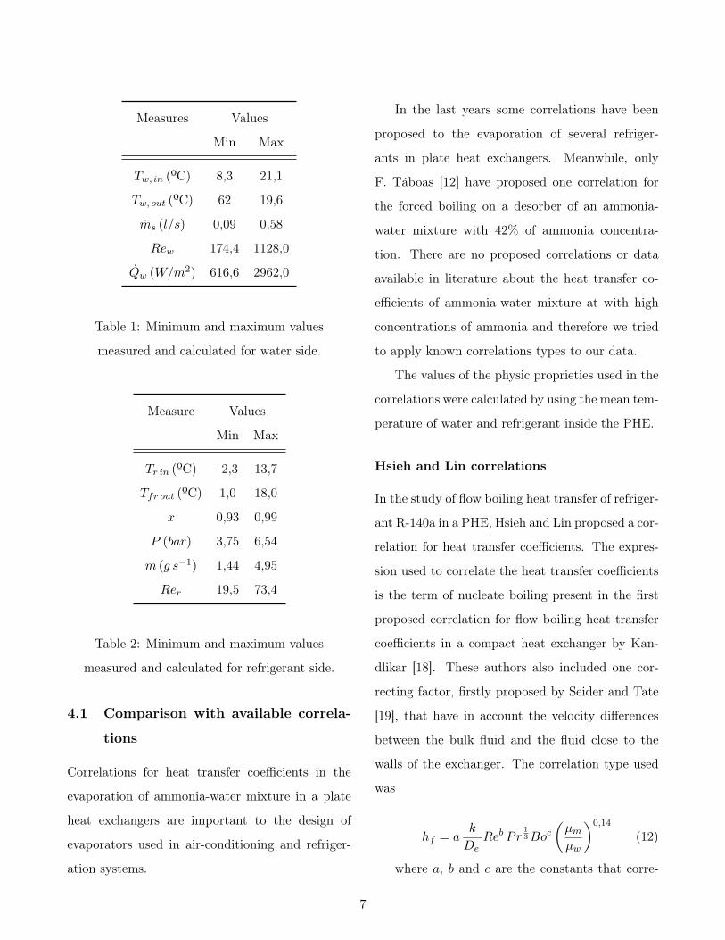
Measures Values
Min Max
Tw, in (ºC) 8,3 21,1
Tw, out (ºC) 62 19,6
ms (l/s) 0,09 0,58
Rew 174,4 1128,0
Qw (W/m2) 616,6 2962,0
Table 1: Minimum and maximum values
measured and calculated for water side.
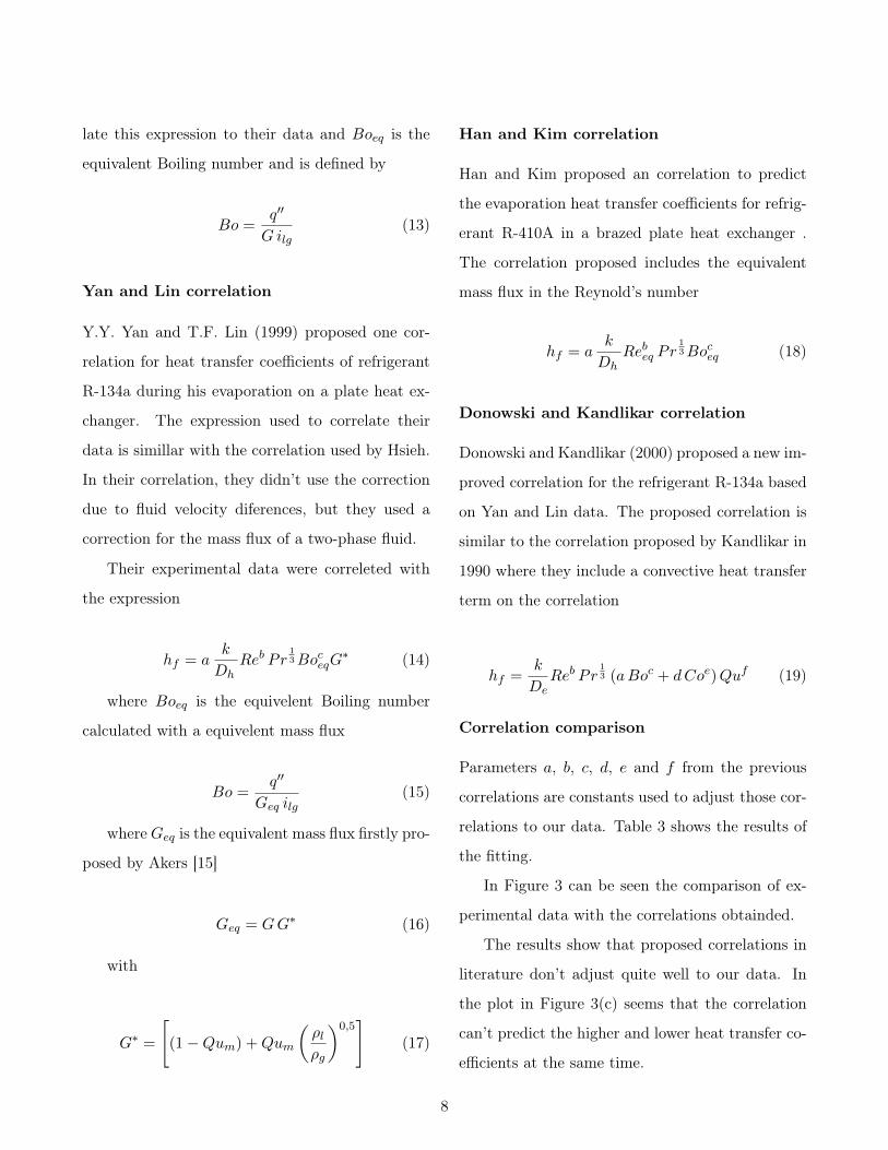
Measure Values
Min Max
Tr in (ºC) -2,3 13,7
Tfr out (ºC) 1,0 18,0
x 0,93 0,99
P (bar) 3,75 6,54
m (g s−1) 1,44 4,95
Rer 19,5 73,4
Table 2: Minimum and maximum values
measured and calculated for refrigerant side.
4.1 Comparison with available correla-
tions
Correlations for heat transfer coefficients in the
evaporation of ammonia-water mixture in a plate
heat exchangers are important to the design of
evaporators used in air-conditioning and refriger-
ation systems.
In the last years some correlations have been
proposed to the evaporation of several refriger-
ants in plate heat exchangers. Meanwhile, only
F. Táboas [12] have proposed one correlation for
the forced boiling on a desorber of an ammonia-
water mixture with 42% of ammonia concentra-
tion. There are no proposed correlations or data
available in literature about the heat transfer co-
efficients of ammonia-water mixture at with high
concentrations of ammonia and therefore we tried
to apply known correlations types to our data.
The values of the physic proprieties used in the
correlations were calculated by using the mean tem-
perature of water and refrigerant inside the PHE.
Hsieh and Lin correlations
In the study of flow boiling heat transfer of refriger-
ant R-140a in a PHE, Hsieh and Lin proposed a cor-
relation for heat transfer coefficients. The expres-
sion used to correlate the heat transfer coefficients
is the term of nucleate boiling present in the first
proposed correlation for flow boiling heat transfer
coefficients in a compact heat exchanger by Kan-
dlikar [18]. These authors also included one cor-
recting factor, firstly proposed by Seider and Tate
[19], that have in account the velocity differences
between the bulk fluid and the fluid close to the
walls of the exchanger. The correlation type used
was
hf = ak
DeReb Pr
13Boc
�µm
µw
�0,14
(12)
where a, b and c are the constants that corre-
7
late this expression to their data and Boeq is the
equivalent Boiling number and is defined by
Bo =q��
Gilg(13)
Yan and Lin correlation
Y.Y. Yan and T.F. Lin (1999) proposed one cor-
relation for heat transfer coefficients of refrigerant
R-134a during his evaporation on a plate heat ex-
changer. The expression used to correlate their
data is simillar with the correlation used by Hsieh.
In their correlation, they didn’t use the correction
due to fluid velocity diferences, but they used a
correction for the mass flux of a two-phase fluid.
Their experimental data were correleted with
the expression
hf = ak
DhReb Pr
13BoceqG
∗ (14)
where Boeq is the equivelent Boiling number
calculated with a equivelent mass flux
Bo =q��
Geq ilg(15)
where Geq is the equivalent mass flux firstly pro-
posed by Akers [15]
Geq = GG∗ (16)
with
G∗ =
�(1−Qum) +Qum
�ρlρg
�0,5�
(17)
Han and Kim correlation
Han and Kim proposed an correlation to predict
the evaporation heat transfer coefficients for refrig-
erant R-410A in a brazed plate heat exchanger .
The correlation proposed includes the equivalent
mass flux in the Reynold’s number
hf = ak
DhRebeq Pr
13Boceq (18)
Donowski and Kandlikar correlation
Donowski and Kandlikar (2000) proposed a new im-
proved correlation for the refrigerant R-134a based
on Yan and Lin data. The proposed correlation is
similar to the correlation proposed by Kandlikar in
1990 where they include a convective heat transfer
term on the correlation
hf =k
DeReb Pr
13 (aBoc + dCoe)Quf (19)
Correlation comparison
Parameters a, b, c, d, e and f from the previous
correlations are constants used to adjust those cor-
relations to our data. Table 3 shows the results of
the fitting.
In Figure 3 can be seen the comparison of ex-
perimental data with the correlations obtainded.
The results show that proposed correlations in
literature don’t adjust quite well to our data. In
the plot in Figure 3(c) seems that the correlation
can’t predict the higher and lower heat transfer co-
efficients at the same time.
8

Correlation Parameter Standard deviation δ%
a b c d e f (W m−2K)
Hsieh 0,607 0,765 0,091 - - - 385 35%
Han and Lin 0,0024 1,072 -0,23 - - - 333 28%
Han and Kim 0,00398 0,94 -0,24 - - - 333 28%
Donowski 0,930 0,771 0,034 -0,726 0,930 -0,258 343 29%
Table 3: Obtained parameters for correlate our data with previous correlations.
+30%
- 30%
0 500 1000 1500 2000 2500 30000
500
1000
1500
2000
2500
3000
hf experimental
h fCa
lcul
ado
hf � a Reb kDe
Pr13 Boeq
c G�
a�
0,00
236;
b�
1,07
2;c��
0,23
3
(a) Yan and Lin correlation
+30%
-30%
0 500 1000 1500 2000 2500 30000
500
1000
1500
2000
2500
3000
hf experimental
h fCalculado
hf � a Reeqb kDePr
13 Boeqc
a�0,00398;b�0,942;c��0,244
(b) Han and Kim correlation
+30%
-30%
0 500 1000 1500 2000 2500 30000
500
1000
1500
2000
2500
3000
hf experimental
h fCalculado
hf � a Reb kDePr
13 Boc � ΜmΜw �0,14
a�0,607;b�0,765;c�0,091
(c) Hsieh correlation
+30%
-30%
0 500 1000 1500 2000 2500 30000
500
1000
1500
2000
2500
3000
hf experimental
h fCalculado
hf � kDeReb Pr
13 �a Boc� d Coe�Qu f
a�0,726;b�0,771;c�0,0345;d��0,726;e�0,192;f��0,258
(d) Donowski correlation
Figure 3: Comparision of experimental heat transfer coefficients with the proposed correlations for
ammonia-water mixture during his evaporation on a PHE.
9

The parameter c in Donowski is negative which
has no physical meaning but can point out that
convective heat transfer isn’t important on this ex-
periment.
According with B. Thonon [16], the heat trans-
fer dependence of nucleate boiling can be determi-
nated by a simple criterion based on the Boiling
number and the Lockhart-Martinelli parameter
Boχ > 0, 15× 10−3 (20)
where χ is the Lockhart-Martinelli parameter
defined as
χ =
�1−Qu
Qu
�0,9�ρgρl
�0,5�µg
µl
�0,1
(21)
Accordingly with this criterion, most of our
data points indicates that heat transfer is governed
by nucleate boiling.
4.2 New proposed correlations
Since previous correlations didn’t fit in our data we
tried to change them in order to get better results.
During the experiments the ammonia concen-
tration on the mixture changed. That change could
affect profile temperatures of the mixture inside of
the PHE in ways that ∆Tln can no longer be a
good approximation to the calculation of global
heat transfer coefficient. Also some thermody-
namic characteristics of the mixture change with
the variation of ammonia concentration, like vis-
cosity, and those proposed correlations may not be
able to predict those variations.
Therefore, we propose to add one parameter
that is function of ammonia concentration to the
previous correlations tested. This way we add a
new multiplier to those correlations in the form of
xg where g is the parameter to be adjusted to the
correlation.
The new proposed correlations we try to test
with our data are then
hf = ak
DeReb Pr
13Boc
�µm
µw
�0,14
xg (22)
hf = ak
DeReb Pr
13Boceq G
∗xg (23)
hf = ak
DeRebeq Pr
13Boceq x
g (24)
hf =k
DeReb Pr
13 (aBoc + dCoe)Qufxg (25)
Table 4 indicates the values obtained for free
parameters of correlations and their relative devia-
tion.
Figure 4 also shows the comparison between
experimental and new predicted heat transfer co-
efficients for the ammonia-water evaporation in a
PHE.
The correction parameter added produced very
satisfactory results. The correlation with a better
result was the equation 25 but according with the
bigger number of free parameters used to fit this
correlation in comparison with others we opted to
consider correlation 24 as the best obtained. Also
the value of fitted parameters in this correlation
seems to be in concordance with others proposed
10
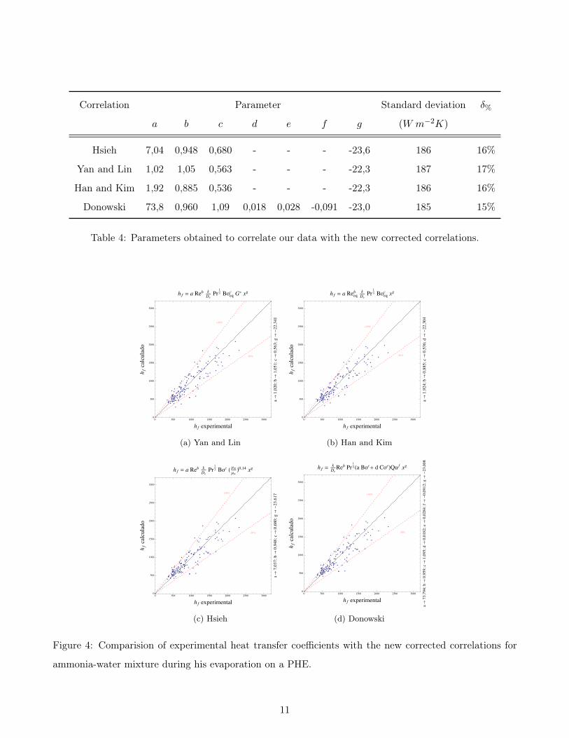
Correlation Parameter Standard deviation δ%
a b c d e f g (W m−2K)
Hsieh 7,04 0,948 0,680 - - - -23,6 186 16%
Yan and Lin 1,02 1,05 0,563 - - - -22,3 187 17%
Han and Kim 1,92 0,885 0,536 - - - -22,3 186 16%
Donowski 73,8 0,960 1,09 0,018 0,028 -0,091 -23,0 185 15%
Table 4: Parameters obtained to correlate our data with the new corrected correlations.
+30%
-30%
0 500 1000 1500 2000 2500 30000
500
1000
1500
2000
2500
3000
hf experimental
h fcalculado
hf � a Reb kDePr
13 Boeqc G� xg
a�1,020;b�1,051;c�0,563;g��22,341
(a) Yan and Lin
+30%
-30%
0 500 1000 1500 2000 2500 30000
500
1000
1500
2000
2500
3000
hf experimental
h fcalculado
hf � a Reeqb kDePr
13 Boeqc xg
a�1,924;b�0,885;c�0,536;d��22,304
(b) Han and Kim
+30%
-30%
0 500 1000 1500 2000 2500 30000
500
1000
1500
2000
2500
3000
hf experimental
h fcalculado
hf � a Reb kDePr
13 Boc � ΜmΜw �0,14 xg
a�7,037;b�0,948;c�0,680;g��23,617
(c) Hsieh
+30%
-30%
0 500 1000 1500 2000 2500 30000
500
1000
1500
2000
2500
3000
hf experimental
h fcalculado
hf � kDeReb Pr
13 �a Boc� d Coe�Qu f xg
a�73,794;b�0,959;c�1,095;d�0,0182;e�0,0284;f��0,0912;g��23,008
(d) Donowski
Figure 4: Comparision of experimental heat transfer coefficients with the new corrected correlations for
ammonia-water mixture during his evaporation on a PHE.
11
correlations in literature for this type of heat trans-
fer.
The correction factor xg varies from 1,24 to 4,93
where the heat transfer coefficients with lowest am-
monia concentration are the ones with the bigger
correction. This can be seen as a correction to the
temperature profile in the PHE for lowest values
of ammonia concentration where the temperatures
of refrigeran tends to increase at the outlet of the
PHE.
5 Conclusions
In order to preform a more precise study on the
heat transfer of ammonia-water mixture evapora-
tion in a PHE a dedicated experiment was needed.
The collected data during the experiments covered
an extense variation of external conditions. How-
ever more data points were needed to study the in-
fluence of some physical quantities (like heat flux,
mass flux, vapor quality, etc) in the heat transfer
coefficients on the ammonia-water evaporation in a
PHE.
To get more accurate heat transfer coefficients
for ammonia-water mixture during his evapora-
tion a new correlation for the heat transfer coef-
ficients from the water side should be find, since
the PHE geometric characteristics influences those
coefficients.
The proposed correlations for heat transfer co-
efficients during the evaporation of a liquid in a
PHE found on literature doesn’t adapt to our data
due to the change of ammonia concentration dur-
ing the experiments on the refrigeration absorption
machine prototype.
A correction to those correlations were pro-
posed as a multiplicative factor function of ammo-
nia concentration which improved the correlations
those correlations to a satisfatory level. The re-
sults and tests to those correlations show that the
introduced correction factor was related with a cor-
rection to the logarithmic mean temperature difer-
ence method used in the calculation of global heat
transfer coefficient.
References
[1] Zahid H. Ayub, 2003, “Plate Heat Exchan-
ger Literature Survey and New Heat Transfer
and Pressure Drop Correlations for Refrige-
rant Evaporators”, Heat Transfer Engineering,
Vol. 24, Nº 5, p. 3-16.
[2] Y.Y. Yan and T.F. Lin, 1999, “Evaporation
Heat Transfer and Pressure Drop of Refrige-
rant R-134a in a Plate Heat Exchanger”, Tran-
sactions of the ASME, Vol. 121, p. 118-127.
[3] V.D. Donowski and S.G. Kandlikar, 2000,
“Correlating Evaporation Heat Transfer Coef-
ficient of Refrigerant R-134a in a Plate Heat
Exchanger”, Engineering Foundation Confe-
rence on Pool and Flow Boiling, Alasca.
[4] Y.Y. Hsieh and T.F. Lin, 2002, “Saturated flow
boiling heat transfer and and pressure drop
12

of refrigerant R-410a in a vertical plate heat
exchanger”, International Journal of Heat and
Mass Transfer, Vol. 44, p. 1033-1044.
[5] D.H. Han, K.J. Lee and Y.H. Kim, 2003, “Ex-
periments on characteristics of evaporation of
R410a in brazed plate heat exchangers with
different geometric configurations”, Applied
Thermal Engineering, Vol. 23, p. 1209–1225.
[6] Y.Y. Hsieh et al, “Subcooled flow boiling heat
transfer of R-134a and the associated bubble
characteristics in a vertical plate heat exchan-
ger”, International Journal of Heat and Mass
Transfer, Vol. 45, p. 1791-1806.
[7] G.A. Longo, A. Gasparella and R. Sartori,
2004, “Experimental heat transfer coefficient
during refrigerant vaporisation and conden-
sation inside herringbone-type plate heat ex-
changers with enhanced surfaces”, Internatio-
nal Journal of Heat and Mass Transfer, Vol.
47, p. 4124–4136.
[8] D. Sterner and B. Sundén, 2006, “Performance
of plate heat exchangers for evaporation of am-
monia”, Heat Transfer Engineering, Vol. 27, p.
45–55.
[9] G.A. Longo and A. Gasparella, 2007, “Refri-
gerant R134a vaporisation heat transfer and
pressure drop inside a small brazed plate heat
exchanger”, International Journal of Refrige-
ration, Vol. 30, p. 821-830.
[10] E. Djordjevic and S. Kabelac, 2008, “Flow boi-
ling of R134a and ammonia in a plate heat
exchanger, International Journal of Heat and
Mass Transfer, Vol. 51, p. 6235-6242.
[11] H. Arima, J.H. Kim, A. Okamoto and Y. Ike-
gami, 2010, “Local boiling heat transfer cha-
racteristics of ammonia in a vertical plate eva-
porator, International Journal of Refrigera-
tion, Vol. 33, p. 359-370.
[12] Francisco Táboas Touceda, 2006, PhD “Estu-
dio del proceso de ebullición forzada de la mez-
cla amoiaco/agua en intercambiadores de pla-
cas para equipos de refrigeración por absor-
ción”, Universidad Rovira i Virgili, Tarragona.
[13] F. Táboas, M. Vallès et al, 2010, “Flow boi-
ling heat transfer of ammonia/water mixture
in plate heat exchanger”, International Journal
of Refrigeration, Vol. 33, p. 695-705
[14] J. Claesson, 2005, “Correction of logarithmic
mean temperature difference in a compacted
brazed plate evaporator assuming heat flux go-
verned flow boiling heat transfer”, Internatio-
nal Journal of Refrigeration, Vol.28, p. 573-578
[15] W.W. Akers, H.A. Deans and O.K. Crosser,
1958, “Condensation heat trasfer within hori-
zontal tubes”, Chemical Engineering Progress,
Vol. 45, p. 89-90.
[16] B. Thonon, A. Feldman, L. Margat and C.
Marvillet, 1997, “Transition from nucleate boi-
ling to convective boiling in compact heat ex-
13

changers”, International Journal of Refrigera-
tion, Vol. 20, p.592-597.
[17] R.K. Shah and A.S. Wanniarachchi, 1992,
“Plate heat exchanger design theory in indus-
try heat exchanger”, Von Karman Institute for
Fluid Dynamics, Bélgica.
[18] S.G. Kandlikar, 1991, “A Model for Flow
Boiling Heat Transfer in Augmented Rubes
and Compact Evaporators”, ASME Journal of
Heat Transfer, Vol. 113, p. 966-972.
[19] Incropera, Dewitt, Bergman and Lavine, 2007,
“Fundamentals of Heat and Mass Transfer”,
John Wiley & Sons.
[20] O.M. Ibrahim, S.A. Klein, 1993, “Termodina-
mic Properties if Ammonia-water Mixtures”,
ASHRAE Transactions, Vol. 99, p. 1495-1502.
14
Nomenclature
A Heat transfer area of the plate [m2]
b Channel spacing [m]
Bo Boiling number
cp specific heat [J kg−1K−1]
Co Convection number
De Equivalent hydraulic diameter [m]
Dh Diâmetro hidráulico
G Mass flux [kgm−2s−1]
Geq Equivalent mass flux [kgm−2s−1]
h Heat transfer coefficient [W m−2K−1]
ilg enthalpy of vaporization [Jkg−1]
k Thermal conductivity [W m−1K−1]
Nu Nulsset number
P Pressure [bar]
Pr Prandlt number
q�� Heat flux [W m−2]
Qu Vapor quality
Re Reynolds number
U Overall heat trasfer coefficient [W m−2K−1]
x ammonia concentration
COP Coefficient of performance
m Mass flow [kgm−2]
Q Heat transfer rate [W ]
Greek symbols
χ Lockhart-Martinelli parameter
∆T Temperature difference [K]
∆Tln Logarithimic mean temperature difference
[K]
∆x Plate wall thickness [m]
δ% Relative mean deviation
µ Viscosity [km−1s−1]
ρ density [kgm−3]
Subscripts
g gas
in inlet
l liquid
m mean
out outlet
r refrigerant
w wall
w water
15