everyday solution for fast-cure chemical anchoring
TRANSCRIPT

EVERYDAY SOLUTION FOR FAST-CURE CHEMICAL ANCHORINGHIT-HY 100 Adhesive Anchor
EVERYDAY SOLUTION FOR FAST-CURE CHEMICAL ANCHORINGHybrid Adhesive HIT-HY 100
Hilti HIT-HY 100 is the everyday fast-cure mortar that provides the quality yoursquove come to expect from Hilti at an economical price HIT-HY 100 has approvals for cracked and un-cracked concrete and grout filled CMU making HIT-HY 100 more versatile for rebar doweling and anchoring
Take reliability safety and productivity to a new level with HIT-HY 100 and SafeSet technology by eliminating the manual hole cleaning step With the TE-CD and TE-YD hollow bits and the VC 150 and VC 300 series vacuums you can increase productivity up to 60 while achieving correct hole preparation and OSHA 19261153 Table 1 compliance
APPLICATIONS AND ADVANTAGESbull Suitable for use in un-cracked
concrete and cracked concrete with all anchor rods and rebar per ICC-ES approval (International Code Council mdash Evaluation Service)
bull Suitable for use in grout-filled CMU for anchor rods per IAPMO-UES (IAPMO-UES (International Association of Plumbing and Mechanical Officials Uniform Evaluation Service)
bull Anchoring light structural steel connections (eg steel columns beams)
bull Rebar doweling connection of secondary post-installed rebar
bull Easy and accurate dispensing with HDE 500-A22 battery dispenser
bull SafeSet technology mdash automatic hole cleaning with TE-CD TE-YD hollow drill bits and VC 150300 vacuum
Technical data
Product Hybrid Urethane Methacrylate
Base material temperature 14deg F to 104deg F (-10deg C to 40deg C)
Diameter range 38rdquo to 1-14rdquo
Package volume bull Volume of HIT-HY 100 111 fl oz330 ml foil pack is 201 in3
bull Volume of HIT-HY 100 169 fl oz500 ml foil pack is 305 in3
Accessories
Description Item number
HDM 500 Manual Dispenser 3498241
HDE 500-A22 Starter Package 3540270
DescriptionQty of
foil packs Item number
HIT-HY 100 (111oz330ml) 1 2078494
HIT-HY 100 Master Carton (111oz330ml) 25 3510989
HIT-HY 100 Master Carton (111oz330ml) + HDM 500 25 3510991
HIT-HY 100 Master Carton (169oz500ml) 20 2078495
(2) HIT-HY 100 Master Cartons (169oz500ml) + HDM 500 40 3511063
(2) HIT-HY 100 Master Cartons (169oz500ml) + HDE 500 Kit 40 3511064
HY 100 TE 50 AVR SafeSet Pack 40 3582040
HIT-HY 100 Technical Supplement
1April 2018
PRODUCT DESCRIPTIONHIT-HY 100 with Threaded Rod Rebar and HIS-NRN Inserts
Mortar system Features and Benefits
Hilti HIT-HY 100 Cartridge
bull No additional hole cleaning required after drilling when installed SafeSettrade hollow drill bit technology
bull ICC-ES approved for cracked concrete and seismic service
bull IAPMO approved for grout-filled concrete masonry
bull Anchoring light structural steel connections (eg steel columns beams)
bull Anchoring secondary steel elements
bull Rebar doweling and connecting secondary post-installed rebar
bull Complete anchor system available including HAS rods HIT-V rods and HIS-N inserts
bull Easy and accurate dispensing with battery dispenser
Threaded RodHASHIT-V
Rebar
Hilti HIS-N
Uncracked concrete
Cracked concrete Grout-filled concrete masonry
Seismic Design Categories
A-F
SafeSet Systemwith Hollow Drill
Bit
PROFIS Anchor design software
ApprovalsListings
ICC-ES (International Code Council Evaluation Service) ESR-3574 (for concrete)
IAPMO-UES (International Association of Plumbing and Mechanical Officials Uniform Evaluation Service)
ER-547 (for grout-filled CMU)
NSFANSI Std 61 Certification for use in potable water
City of Los Angeles LABC Supplement in ESR-3574
US Green Building Council LEEDreg Credit 41-Low Emitting Materials
Department of Transportation Contact Hilti for various states
2 April 2018
DESIGN DATA IN CONCRETE PER ACI 318 ACI 318-14 Chapter 17 design The technical data contained in this section are Hilti Simplified Design Tables The load values were developed using the Strength Design parameters developed through testing per ACI 3554 and the equations within ACI 318-14 Chapter 17 For a detailed explanation of the Hilti Simplified Design Tables refer to of the Hilti North American Product Technical Guide Volume 2 Anchor Fastening Technical Guide Edition 17
For additional information or technical assistance contact Hilti at 800-879-5000 (US) or 800-363-4459 (CA)
Hilti HIT-HY 100 Adhesive with Deformed Reinforcing Bars (Rebar)
Rebar installation conditions
Perm
issi
ble
Bas
e M
ater
ials
Uncracked concrete
DryConcrete
Perm
issi
ble
Dril
ling
Met
hod
Hammer Drilling with Carbide Tipped
Drill Bit
Cracked concrete
Water Saturated Concrete
Hollow Drill Bit
US rebar installation specifications
RebarSize
DrillBit
Dia
StandardEmbedDepth
EmbedDepthRange
MinimumBase Material
Thickness
d0in
hef stdin (mm)
hefin (mm)
hminin (mm)
3 123-38 2-38 ndash 7-12
hef + 1-14(hef + 30)
(86) (60 ndash 191)
4 584-12 2-34 ndash 10
(114) (70 ndash 254)
5 345-58 3-18 ndash 12-12
hef + 2d0
(143) (79 ndash 318)
6 786-34 3-12 ndash 15
(171) (89 ndash 381)
7 17-78 3-12 ndash 17-12
(200) (89 ndash 445)
8 1-189 4 ndash 20
(229) (102 ndash 508)
9 1-3810-18 4-12 ndash 22-12
(257) (114 ndash 572)
10 1-1211-14 5 ndash 25
(286) (127 ndash 635)
Canadian rebar installation specifications
RebarSize
DrillBit
Dia
StandardEmbedDepth
EmbedDepthRange
MinimumBase Material
Thickness
d0in
hef stdmm
hefmm
hminmm
10 M 916 115 70 ndash 226 hef + 30
15 M 34 145 80 ndash 320
hef + 2d0
20 M 1 200 90 ndash 390
25 M 1-14 230 101 ndash 504
30 M 1-12 260 120 ndash 598
HIT-HY 100 Technical Supplement
3April 2018
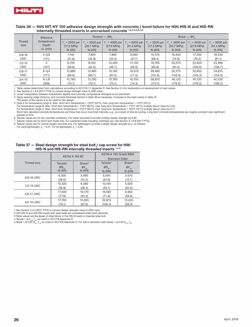
Table 1 mdash Hilti HIT-HY 100 adhesive design strength with concrete bond failure for US rebar in uncracked concrete 12345678
Rebar sizeEffective
embedmentin (mm)
Tension mdash ϕNn Shear mdash ϕVn
f c = 2500 psi(172 Mpa)
lb (kN)
f c = 3000 psi(207 Mpa)
lb (kN)
f c = 4000 psi(276 Mpa)
lb (kN)
f c = 6000 psi(414 Mpa)
lb (kN)
f c = 2500 psi(172 Mpa)
lb (kN)
f c = 3000 psi(207 Mpa)
lb (kN)
f c = 4000 psi(276 Mpa)
lb (kN)
f c = 6000 psi(414 Mpa)
lb (kN)
3
3-38 3295 3355 3455 3595 7095 7230 7440 7745(86) (147) (149) (154) (160) (316) (322) (331) (345)
4-12 4395 4475 4605 4795 9465 9635 9920 10330(114) (195) (199) (205) (213) (421) (429) (441) (459)7-12 7325 7455 7675 7995 15770 16060 16530 17215(191) (326) (332) (341) (356) (701) (714) (735) (766)
4
4-12 5810 5920 6090 6345 12520 12750 13120 13665(114) (258) (263) (271) (282) (557) (567) (584) (608)
6 7750 7890 8120 8460 16690 17000 17495 18220(152) (345) (351) (361) (376) (742) (756) (778) (810)10 12915 13155 13535 14100 27820 28330 29160 30365
(254) (574) (585) (602) (627) (1237) (1260) (1297) (1351)
5
5-58 8995 9160 9430 9820 19375 19730 20305 21145(143) (400) (407) (419) (437) (862) (878) (903) (941)7-12 11995 12215 12570 13090 25835 26310 27075 28195(191) (534) (543) (559) (582) (1149) (1170) (1204) (1254)
12-12 19990 20355 20950 21820 43055 43845 45125 46995(318) (889) (905) (932) (971) (1915) (1950) (2007) (2090)
6
6-34 12820 13055 13435 13990 27610 28120 28940 30135(171) (570) (581) (598) (622) (1228) (1251) (1287) (1340)
9 17090 17405 17915 18655 36815 37490 38585 40180(229) (760) (774) (797) (830) (1638) (1668) (1716) (1787)
15 28485 29010 29855 31095 61355 62485 64310 66970(381) (1267) (1290) (1328) (1383) (2729) (2779) (2861) (2979)
7
7-78 17235 17625 18140 18890 37125 37965 39070 40690(200) (767) (784) (807) (840) (1651) (1689) (1738) (1810)
10-12 23075 23500 24185 25190 49705 50615 52095 54250(267) (1026) (1045) (1076) (1121) (2211) (2251) (2317) (2413)17-12 38460 39170 40310 41980 82840 84360 86825 90415(445) (1711) (1742) (1793) (1867) (3685) (3753) (3862) (4022)
8
9 21060 22835 23500 24475 45360 49180 50615 52710(229) (937) (1016) (1045) (1089) (2018) (2188) (2251) (2345)
12 29895 30445 31335 32630 64390 65575 67490 70280(305) (1330) (1354) (1394) (1451) (2864) (2917) (3002) (3126)
20 49825 50740 52225 54385 107315 109290 112480 117135(508) (2216) (2257) (2323) (2419) (4774) (4861) (5003) (5210)
9
10-18 22635 23050 23725 24705 54125 58675 60385 62885(257) (1007) (1025) (1055) (1099) (2408) (2610) (2686) (2797)
13-12 30180 30735 31630 32940 76820 78230 80515 83845(343) (1342) (1367) (1407) (1465) (3417) (3480) (3581) (3730)
22-12 50295 51225 52720 54900 128030 130385 134190 139745(572) (2237) (2279) (2345) (2442) (5695) (5800) (5969) (6216)
10
11-14 25025 25490 26230 27315 63395 64880 66770 69535(286) (1113) (1134) (1167) (1215) (2820) (2886) (2970) (3093)
15 33370 33985 34975 36425 84940 86505 89030 92710(381) (1484) (1512) (1556) (1620) (3778) (3848) (3960) (4124)25 55615 56640 58290 60705 141570 144175 148380 154520
(635) (2474) (2519) (2593) (2700) (6297) (6413) (6600) (6873)1 See Section 318 (2017 PTG) for explanation on development of load values2 See Section 3186 (2017 PTG) to convert design strength value to ASD value3 Linear interpolation between embedment depths and concrete compressive strengths is not permitted4 Load values are for a single anchor with no spacing edge distance or concrete thickness factors Apply spacing edge distance and concrete thickness factors in tables 4-19 as
necessary Compare to the steel values in table 3 The lesser of the values is to be used for the design5 Data is for temperature range A Max short term temperature = 130degF (55degC) max long term temperature = 110degF (43degC)
For temperature range B Max short term temperature = 176degF (80degC) max long term temperature = 110degF (43degC) multiply above value by 092 For temperature range C Max short term temperature = 210degF (99degC) max long term temperature = 162degF (72degC) multiply above value by 071 Short term elevated concrete temperatures are those that occur over brief intervals eg as a result of diurnal cycling Long term concrete temperatures are roughly constant over significant periods of time
6 Tabular values are for dry concrete conditions For water saturated concrete multiply design strength (factored resistance) by 0857 Tabular values are for short term loads only For sustained loads including overhead use see Section 3188 (2017 PTG)8 Tabular values are for normal-weight concrete only For lightweight concrete multiply design strength by λa as follows
For sand-lightweight λa = 051 For all-lightweight λa = 045
4 April 2018
Table 2 mdash Hilti HIT-HY 100 adhesive design strength with concrete bond failure for US rebar in cracked concrete 12345678
Rebar sizeEffective
embedmentin (mm)
Tension mdash ϕNn Shear mdash ϕVn
f´c = 2500 psi(172 Mpa)
lb (kN)
f´c = 3000 psi(207 Mpa)
lb (kN)
f´c = 4000 psi(276 Mpa)
lb (kN)
f´c = 6000 psi(414 Mpa)
lb (kN)
f´c = 2500 psi(172 Mpa)
lb (kN)
f´c = 3000 psi(207 Mpa)
lb (kN)
f´c = 4000 psi(276 Mpa)
lb (kN)
f´c = 6000 psi(414 Mpa)
lb (kN)
3
3-38 1575 1605 1650 1720 3395 3460 3560 3705(86) (70) (71) (73) (77) (151) (154) (158) (165)
4-12 2100 2140 2205 2295 4525 4610 4745 4940(114) (93) (95) (98) (102) (201) (205) (211) (220)7-12 3505 3570 3670 3825 7545 7685 7910 8235(191) (156) (159) (163) (170) (336) (342) (352) (366)
4
4-12 3080 3135 3225 3360 6630 6750 6950 7235(114) (137) (139) (143) (149) (295) (300) (309) (322)
6 4105 4180 4300 4480 8840 9005 9265 9650(152) (183) (186) (191) (199) (393) (401) (412) (429)10 6840 6965 7170 7465 14735 15005 15445 16080
(254) (304) (310) (319) (332) (655) (667) (687) (715)
5
5-58 5205 5300 5455 5680 11210 11415 11750 12235(143) (232) (236) (243) (253) (499) (508) (523) (544)7-12 6940 7065 7275 7575 14945 15220 15665 16315(191) (309) (314) (324) (337) (665) (677) (697) (726)
12-12 11565 11780 12125 12625 24910 25370 26110 27190(318) (514) (524) (539) (562) (1108) (1129) (1161) (1209)
6
6-34 8010 8160 8395 8745 17255 17575 18085 18835(171) (356) (363) (373) (389) (768) (782) (804) (838)
9 10680 10880 11195 11660 23010 23430 24115 25115(229) (475) (484) (498) (519) (1024) (1042) (1073) (1117)
15 17805 18130 18660 19435 38345 39055 40190 41855(381) (792) (806) (830) (865) (1706) (1737) (1788) (1862)
7
7-78 10975 11175 11505 11980 23640 24075 24775 25800(200) (488) (497) (512) (533) (1052) (1071) (1102) (1148)
10-12 14635 14905 15340 15975 31520 32100 33035 34405(267) (651) (663) (682) (711) (1402) (1428) (1469) (1530)17-12 24390 24840 25565 26620 52530 53500 55060 57340(445) (1085) (1105) (1137) (1184) (2337) (2380) (2449) (2551)
8
9 14520 14785 15220 15845 31270 31845 32775 34135(229) (646) (658) (677) (705) (1391) (1417) (1458) (1518)
12 19360 19715 20290 21130 41695 42460 43700 45510(305) (861) (877) (903) (940) (1855) (1889) (1944) (2024)
20 32265 32860 33815 35215 69490 70770 72835 75850(508) (1435) (1462) (1504) (1566) (3091) (3148) (3240) (3374)
9
10-18 15645 15935 16400 17080 38340 40560 41745 43470(257) (696) (709) (730) (760) (1705) (1804) (1857) (1934)
13-12 20860 21245 21865 22770 53105 54080 55660 57965(343) (928) (945) (973) (1013) (2362) (2406) (2476) (2578)
22-12 34770 35410 36445 37950 88510 90135 92765 96605(572) (1547) (1575) (1621) (1688) (3937) (4009) (4126) (4297)
10
11-14 19560 19920 20500 21350 44905 49190 52185 54345(286) (870) (886) (912) (950) (1997) (2188) (2321) (2417)
15 26080 26560 27335 28465 66385 67605 69580 72460(381) (1160) (1181) (1216) (1266) (2953) (3007) (3095) (3223)25 43465 44265 45560 47445 110645 112680 115965 120765
(635) (1921) (1957) (2014) (2097) (4891) (4981) (5126) (5339)1 See Section 318 (2017 PTG) for explanation on development of load values2 See Section 3186 (2017 PTG) to convert design strength value to ASD value3 Linear interpolation between embedment depths and concrete compressive strengths is not permitted4 Load values are for a single anchor with no spacing edge distance or concrete thickness factors Apply spacing edge distance and concrete thickness factors in tables 4-19 as
necessary Compare to the steel values in table 3 The lesser of the values is to be used for the design5 Data is for temperature range A Max short term temperature = 104degF (40degC) max long term temperature = 75degF (24degC)
For temperature range B Max short term temperature = 176degF (80degC) max long term temperature = 110degF (43degC) multiply above value by 092 For temperature range C Max short term temperature = 210degF (99degC) max long term temperature = 162degF (72degC) multiply above value by 071 Short term elevated concrete temperatures are those that occur over brief intervals eg as a result of diurnal cycling Long term concrete temperatures are roughly constant over significant periods of time
6 Tabular values are for dry concrete conditions For water saturated concrete multiply design strength (factored resistance) by 0857 Tabular values are for short term loads only For sustained loads including overhead use see Section 3188 (2017 PTG)8 Tabular values are for normal-weight concrete only For lightweight concrete multiply design strength by λa as follows
For sand-lightweight λa = 051 For all-lightweight λa = 0459 Tabular values are for static loads only For seismic loads multiply cracked concrete tabular values in tension and shear by αseis = 075 See section 3187 (2017 PTG) for additional information on seismic applications
HIT-HY 100 Technical Supplement
5April 2018
Table 3 mdash Steel design strength for US rebar 12
Rebar size
ASTM A 615 Grade 40 ASTM A 615 Grade 60 ASTM A 706 Grade 60
Tensile3
ϕNsalb (kN)
Shear4
ϕVsalb (kN)
Seismic Shear5
ϕVsaeqlb (kN)
Tensile3
ϕNsalb (kN)
Shear4
ϕVsalb (kN)
Seismic Shear5
ϕVsaeqlb (kN)
Tensile3
ϕNsalb (kN)
Shear4
ϕVsalb (kN)
Seismic Shear5
ϕVsaeqlb (kN)
34290 2375 1665 6435 3565 2495 6600 3430 2400(191) (106) (74) (286) (159) (111) (294) (153) (107)
47800 4320 3025 11700 6480 4535 12000 6240 4370(347) (192) (135) (520) (288) (202) (534) (278) (194)
512090 6695 4685 18135 10045 7030 18600 9670 6770(538) (298) (208) (807) (447) (313) (827) (430) (301)
617160 9505 6655 25740 14255 9980 26400 13730 9610(763) (423) (296) (1145) (634) (444) (1174) (611) (427)
723400 12960 9070 35100 19440 13610 36000 18720 13105(1041) (576) (403) (1561) (865) (605) (1601) (833) (583)
830810 17065 11945 46215 25595 17915 47400 24650 17255(1370) (759) (531) (2056) (1139) (797) (2108) (1096) (768)
939000 21600 15120 58500 32400 22680 60000 31200 21840(1735) (961) (673) (2602) (1441) (1009) (2669) (1388) (971)
1049530 27430 19200 74295 41150 28805 76200 39625 27740(2203) (1220) (854) (3305) (1830) (1281) (3390) (1763) (1234)
1 See Section 3186 (2017 PTG) to convert design strength value to ASD value2 ASTM A706 Grade 60 rebar are considered ductile steel elements ASTM A 615 Grade 40 and 60 rebar are considered brittle steel elements3 Tensile = ϕ AseN futa as noted in ACI 318 Chapter 174 Shear = ϕ 060 AseN futa as noted in ACI 318 Chapter 175 Seismic Shear = αVseis ϕVsa Reduction for seismic shear only See section 3187 (2017 PTG) for additional information on seismic applications
6 April 2018
Table 4 mdash Load adjustment factors for 3 rebar in uncracked concrete 123
3Uncracked concrete
Spacing factor in tension
fAN
Edge distance factor in tension
fRN
Spacing factor in shear 4
fAV
Edge distance in shearConcrete thickness
factor in shear 5
fHV
Toward edge
fRV
To edge
fRV
Embedment hefin (mm)
3-38 4-12 7-12 3-38 4-12 7-12 3-38 4-12 7-12 3-38 4-12 7-12 3-38 4-12 7-12 3-38 4-12 7-12(86) (114) (191) (86) (114) (191) (86) (114) (191) (86) (114) (191) (86) (114) (191) (86) (114) (191)
Spac
ing
(s)
edg
e di
stan
ce (c
a) c
oncr
ete
thic
knes
s (h
) - i
n (m
m)
1-34 (44) na na na 032 023 013 na na na 010 008 005 021 016 009 na na na1-78 (48) 059 057 054 033 024 014 054 053 052 012 009 005 023 017 010 na na na
2 (51) 060 057 054 034 025 014 054 053 052 013 010 006 025 019 011 na na na3 (76) 065 061 057 042 031 018 056 055 054 023 017 010 042 031 018 na na na4 (102) 070 065 059 052 038 022 058 057 055 036 027 016 052 038 022 na na na
4-58 (117) 073 067 060 060 043 025 060 058 056 045 033 020 060 043 025 062 na na5 (127) 075 069 061 064 047 027 061 059 056 050 038 023 064 047 027 065 na na
5-34 (146) 078 071 063 074 054 031 062 060 057 062 046 028 074 054 031 070 063 na6 (152) 080 072 063 077 056 033 063 060 057 066 049 030 077 056 033 071 065 na7 (178) 085 076 066 090 066 038 065 062 059 083 062 037 090 066 038 077 070 na8 (203) 090 080 068 100 075 043 067 064 060 100 076 046 100 075 043 082 075 na
8-34 (222) 093 082 069 082 048 068 065 061 087 052 082 048 086 078 0669 (229) 094 083 070 084 049 069 066 061 091 055 084 049 087 079 06710 (254) 099 087 072 094 054 071 067 062 100 064 094 054 092 083 07011 (279) 100 091 074 100 060 073 069 064 074 100 060 096 087 07412 (305) 094 077 065 075 071 065 084 065 100 091 07714 (356) 100 081 076 079 074 067 100 076 099 08316 (406) 086 087 084 078 070 087 100 08918 (457) 090 098 088 081 072 098 09424 (610) 100 100 100 092 080 100 10030 (762) 100 08736 (914) 094
gt 48 (1219) 100
Table 5 mdash Load adjustment factors for 3 rebar in cracked concrete 123
3Cracked concrete
Spacing factor in tension
fAN
Edge distance factor in tension
fRN
Spacing factor in shear 4
fAV
Edge distance in shearConcrete thickness
factor in shear 5
fHV
Toward edge
fRV
To edge
fRV
Embedment hefin (mm)
3-38 4-12 7-12 3-38 4-12 7-12 3-38 4-12 7-12 3-38 4-12 7-12 3-38 4-12 7-12 3-38 4-12 7-12(86) (114) (191) (86) (114) (191) (86) (114) (191) (86) (114) (191) (86) (114) (191) (86) (114) (191)
Spac
ing
(s)
edg
e di
stan
ce (c
a) c
oncr
ete
thic
knes
s (h
) - i
n (m
m)
1-34 (44) na na na 054 049 043 na na na 010 007 004 020 015 009 na na na1-78 (48) 059 057 054 056 050 044 054 053 052 011 008 005 022 017 010 na na na
2 (51) 060 057 054 057 051 044 054 053 052 012 009 005 024 018 011 na na na3 (76) 065 061 057 070 060 049 056 055 054 022 017 010 045 034 020 na na na4 (102) 070 065 059 084 070 055 058 057 055 034 026 015 069 052 031 na na na
4-58 (117) 073 067 060 093 076 058 059 058 056 043 032 019 086 064 038 062 na na5 (127) 075 069 061 099 080 060 060 058 056 048 036 022 096 072 043 064 na na
5-34 (146) 078 071 063 100 088 064 062 060 057 059 044 027 100 088 053 069 062 na6 (152) 080 072 063 091 066 062 060 057 063 047 028 091 057 070 064 na7 (178) 085 076 066 100 072 064 062 058 080 060 036 100 072 076 069 na8 (203) 090 080 068 078 066 064 060 097 073 044 078 081 074 na
8-34 (222) 093 082 069 083 068 065 061 100 083 050 083 085 077 0659 (229) 094 083 070 085 068 065 061 087 052 085 086 078 06610 (254) 099 087 072 091 070 067 062 100 061 091 090 082 06911 (279) 100 091 074 098 073 069 063 071 098 095 086 07312 (305) 094 077 100 075 070 064 080 100 099 090 07614 (356) 100 081 100 079 074 067 100 100 097 08216 (406) 086 083 077 069 100 08818 (457) 090 087 080 072 09324 (610) 100 099 091 079 10030 (762) 100 100 08636 (914) 093
gt 48 (1219) 1001 Linear interpolation not permitted2 Shaded area with reduced edge distance is permitted provided the rebar has no installation torque3 When combining multiple load adjustment factors (eg for a four-anchor pattern in a corner with thin concrete member) the design can become very conservative To optimize the design
use Hilti PROFIS Anchor Design software or perform anchor calculation using design equations from ACI 318 Chapter 174 Spacing factor reduction in shear applicable when ca lt 3hef ƒAV is applicable when edge distance ca lt 3hef If ca ge 3hef then ƒAV = ƒAN 5 Concrete thickness reduction factor in shear ƒHV is applicable when edge distance ca lt 3hef If ca ge 3hef then ƒHV = 10
HIT-HY 100 Technical Supplement
7April 2018
Table 6 mdash Load adjustment factors for 4 rebar in uncracked concrete 123
4Uncracked concrete
Spacing factor in tension
fAN
Edge distance factor in tension
fRN
Spacing factor in shear 4
fAV
Edge distance in shearConcrete thickness
factor in shear 5
fHV
Toward edge
fRV
To edge
fRV
Embedment hefin (mm)
4-12 6 10 4-12 6 10 4-12 6 10 4-12 6 10 4-12 6 10 4-12 6 10 (114) (152) (254) (114) (152) (254) (114) (152) (254) (114) (152) (254) (114) (152) (254) (114) (152) (254)
Spac
ing
(s)
edg
e di
stan
ce (c
a) c
oncr
ete
thic
knes
s (h
) - i
n (m
m)
1-34 (44) na na na 027 020 012 na na na 007 005 003 014 010 006 na na na2-12 (64) 059 057 054 032 023 014 054 053 052 012 009 005 023 017 010 na na na
3 (76) 061 058 055 035 026 015 055 054 053 015 011 007 031 023 014 na na na4 (102) 065 061 057 041 030 018 056 055 054 023 018 011 041 030 018 na na na5 (127) 069 064 058 048 035 021 058 057 055 033 025 015 048 035 021 na na na
5-34 (146) 071 066 060 054 040 023 059 058 055 040 030 018 054 040 023 060 na na6 (152) 072 067 060 056 041 024 060 058 056 043 032 019 056 041 024 062 na na7 (178) 076 069 062 066 048 028 061 059 057 054 041 024 066 048 028 067 na na
7-14 (184) 077 070 062 068 050 029 062 059 057 057 043 026 068 050 029 068 062 na8 (203) 080 072 063 075 055 032 063 060 057 066 050 030 075 055 032 071 065 na9 (229) 083 075 065 085 062 036 064 062 058 079 059 036 085 062 036 076 069 na10 (254) 087 078 067 094 069 040 066 063 059 093 070 042 094 069 040 080 072 na
11-14 (286) 092 081 069 100 078 045 068 065 060 100 083 050 100 078 045 084 077 06512 (305) 094 083 070 083 048 069 066 061 092 055 083 048 087 079 06714 (356) 100 089 073 097 056 072 068 063 100 069 097 056 094 086 07216 (406) 094 077 100 065 075 071 065 085 100 065 100 092 07718 (457) 100 080 073 079 074 067 100 073 097 08220 (508) 083 081 082 076 069 081 100 08622 (559) 087 089 085 079 070 089 09124 (610) 090 097 088 081 072 097 09530 (762) 100 100 098 089 078 100 10036 (914) 100 097 084
gt 48 (1219) 100 095
Table 7 mdash Load adjustment factors for 4 rebar in cracked concrete 123
4Cracked concrete
Spacing factor in tension
fAN
Edge distance factor in tension
fRN
Spacing factor in shear 4
fAV
Edge distance in shearConcrete thickness
factor in shear 5
fHV
Toward edge
fRV
To edge
fRV
Embedment hefin (mm)
4-12 6 10 4-12 6 10 4-12 6 10 4-12 6 10 4-12 6 10 4-12 6 10 (114) (152) (254) (114) (152) (254) (114) (152) (254) (114) (152) (254) (114) (152) (254) (114) (152) (254)
Spac
ing
(s)
edg
e di
stan
ce (c
a) c
oncr
ete
thic
knes
s (h
) - i
n (m
m)
1-34 (44) na na na 049 045 041 na na na 006 005 003 013 010 006 na na na2-12 (64) 059 057 054 056 050 044 054 053 052 011 008 005 022 017 010 na na na
3 (76) 061 058 055 060 053 046 055 054 053 015 011 007 029 022 013 na na na4 (102) 065 061 057 070 060 049 056 055 054 022 017 010 045 034 020 na na na5 (127) 069 064 058 080 067 053 058 056 055 031 023 014 062 047 028 na na na
5-34 (146) 071 066 060 088 073 056 059 057 055 039 029 017 077 058 035 059 na na6 (152) 072 067 060 091 075 057 059 058 055 041 031 018 082 062 037 061 na na7 (178) 076 069 062 100 083 062 061 059 056 052 039 023 100 078 047 066 na na
7-14 (184) 077 070 062 085 063 061 059 057 055 041 025 082 049 067 061 na8 (203) 080 072 063 091 066 062 060 057 063 047 028 091 057 070 064 na9 (229) 083 075 065 100 070 064 061 058 075 057 034 100 068 074 068 na10 (254) 087 078 067 075 065 063 059 088 066 040 075 078 071 na
11-14 (286) 092 081 069 081 067 064 060 100 079 047 081 083 075 06412 (305) 094 083 070 085 068 065 061 087 052 085 086 078 06614 (356) 100 089 073 095 071 068 063 100 066 095 093 084 07116 (406) 094 077 100 075 070 064 080 100 099 090 07618 (457) 100 080 078 073 066 096 100 095 08120 (508) 083 081 075 068 100 100 08522 (559) 087 084 078 070 08924 (610) 090 087 080 072 09330 (762) 100 096 088 077 10036 (914) 100 096 082
gt 48 (1219) 100 0931 Linear interpolation not permitted2 Shaded area with reduced edge distance is permitted provided the rebar has no installation torque3 When combining multiple load adjustment factors (eg for a four-anchor pattern in a corner with thin concrete member) the design can become very conservative To optimize the design
use Hilti PROFIS Anchor Design software or perform anchor calculation using design equations from ACI 318 Chapter 174 Spacing factor reduction in shear applicable when ca lt 3hef ƒAV is applicable when edge distance ca lt 3hef If ca ge 3hef then ƒAV = ƒAN 5 Concrete thickness reduction factor in shear ƒHV is applicable when edge distance ca lt 3hef If ca ge 3hef then ƒHV = 10
8 April 2018
Table 8 mdash Load adjustment factors for 5 rebar in uncracked concrete 123
5Uncracked concrete
Spacing factor in tension
fAN
Edge distance factor in tension
fRN
Spacing factor in shear 4
fAV
Edge distance in shearConcrete thickness
factor in shear 5
fHV
Toward edge
fRV
To edge
fRV
Embedment hefin (mm)
5-58 7-12 12-12 5-58 7-12 12-12 5-58 7-12 12-12 5-58 7-12 12-12 5-58 7-12 12-12 5-58 7-12 12-12(143) (191) (318) (143) (191) (318) (143) (191) (318) (143) (191) (318) (143) (191) (318) (143) (191) (318)
Spac
ing
(s)
edg
e di
stan
ce (c
a) c
oncr
ete
thic
knes
s (h
) - i
n (m
m)
1-34 (44) na na na 025 019 011 na na na 005 004 002 010 007 004 na na na2-12 (64) 059 057 054 032 023 014 054 053 052 012 009 005 023 018 011 na na na
3 (76) 062 059 055 036 026 015 055 054 053 017 013 008 034 025 015 na na na4 (102) 065 061 057 041 030 018 056 055 054 024 018 011 041 030 018 na na na5 (127) 068 063 058 047 034 020 058 056 055 031 023 014 047 034 020 na na na
5-34 (146) 071 066 059 053 039 023 059 057 055 039 029 018 053 039 023 na na na6 (152) 071 066 060 054 039 023 059 058 055 040 030 018 054 039 023 060 na na7 (178) 074 068 061 060 044 026 060 058 056 048 036 022 060 044 026 064 na na
7-14 (184) 077 070 062 068 050 029 061 059 057 057 043 026 068 050 029 068 062 na8 (203) 080 072 063 075 055 032 063 061 058 067 050 030 075 055 032 071 065 na9 (229) 083 074 065 083 061 036 064 062 058 077 058 035 083 061 036 075 068 na10 (254) 086 077 066 090 066 039 065 063 059 088 066 040 090 066 039 078 071 na
11-14 (286) 091 081 069 100 077 045 068 065 061 100 083 050 100 077 045 085 077 06512 (305) 097 086 071 088 052 070 067 062 100 061 088 052 090 082 06914 (356) 100 090 074 099 058 073 069 064 073 099 058 096 087 07316 (406) 094 077 100 065 076 071 065 085 100 065 100 092 07718 (457) 099 079 071 078 073 067 099 071 096 08120 (508) 100 082 078 081 075 068 100 078 100 08522 (559) 085 084 083 077 070 084 08824 (610) 087 091 086 080 071 091 09230 (762) 090 097 088 082 073 097 09536 (914) 098 100 096 088 077 100 100
gt 48 (1219) 100 100 100 086
Table 9 mdash Load adjustment factors for 5 rebar in cracked concrete 123
5Cracked concrete
Spacing factor in tension
fAN
Edge distance factor in tension
fRN
Spacing factor in shear 4
fAV
Edge distance in shearConcrete thickness
factor in shear 5
fHV
Toward edge
fRV
To edge
fRV
Embedment hefin (mm)
5-58 7-12 12-12 5-58 7-12 12-12 5-58 7-12 12-12 5-58 7-12 12-12 5-58 7-12 12-12 5-58 7-12 12-12(143) (191) (318) (143) (191) (318) (143) (191) (318) (143) (191) (318) (143) (191) (318) (143) (191) (318)
Spac
ing
(s)
edg
e di
stan
ce (c
a) c
oncr
ete
thic
knes
s (h
) - i
n (m
m)
1-34 (44) na na na 046 043 040 na na na 005 003 002 009 007 004 na na na2-12 (64) 059 057 054 056 050 044 054 053 052 011 008 005 022 017 010 na na na
3 (76) 062 059 055 062 055 046 055 054 053 016 012 007 032 024 014 na na na4 (102) 065 061 057 070 060 049 056 055 054 022 017 010 045 034 020 na na na5 (127) 068 063 058 078 066 053 057 056 054 029 022 013 059 044 026 na na na
5-34 (146) 071 066 059 087 072 056 059 057 055 037 028 017 074 056 033 na na na6 (152) 071 066 060 088 073 056 059 057 055 038 029 017 076 057 034 059 na na7 (178) 074 068 061 096 078 059 060 058 056 045 034 020 090 068 041 063 na na
7-14 (184) 077 070 062 100 085 062 061 059 056 054 040 024 100 081 049 066 060 na8 (203) 080 072 063 091 066 062 060 057 063 047 028 091 057 070 064 na9 (229) 083 074 065 098 069 064 061 058 073 055 033 098 066 073 067 na10 (254) 086 077 066 100 073 065 062 059 083 062 037 100 073 077 070 na
11-14 (286) 091 081 069 081 067 064 060 100 079 047 081 083 075 06412 (305) 097 086 071 089 070 066 062 096 058 089 089 081 06814 (356) 100 090 074 097 072 068 063 100 069 097 094 085 07216 (406) 094 077 100 075 070 064 080 100 099 090 07618 (457) 099 079 077 072 066 093 100 094 08020 (508) 100 082 079 074 067 100 099 08322 (559) 085 082 076 069 100 08724 (610) 087 084 078 070 09030 (762) 090 087 080 072 09336 (914) 098 094 086 076 100
gt 48 (1219) 100 100 099 0851 Linear interpolation not permitted2 Shaded area with reduced edge distance is permitted provided the rebar has no installation torque3 When combining multiple load adjustment factors (eg for a four-anchor pattern in a corner with thin concrete member) the design can become very conservative To optimize the design
use Hilti PROFIS Anchor Design software or perform anchor calculation using design equations from ACI 318 Chapter 174 Spacing factor reduction in shear applicable when ca lt 3hef ƒAV is applicable when edge distance ca lt 3hef If ca ge 3hef then ƒAV = ƒAN 5 Concrete thickness reduction factor in shear ƒHV is applicable when edge distance ca lt 3hef If ca ge 3hef then ƒHV = 10
HIT-HY 100 Technical Supplement
9April 2018
Table 10 mdash Load adjustment factors for 6 rebar in uncracked concrete 123
6Uncracked concrete
Spacing factor in tension
fAN
Edge distance factor in tension
fRN
Spacing factor in shear 4
fAV
Edge distance in shearConcrete thickness
factor in shear 5
fHV
Toward edge
fRV
To edge
fRV
Embedment hefin (mm)
6-34 9 15 6-34 9 15 6-34 9 15 6-34 9 15 6-34 9 15 6-34 9 15 (171) (229) (381) (171) (229) (381) (171) (229) (381) (171) (229) (381) (171) (229) (381) (171) (229) (381)
Spac
ing
(s)
edg
e di
stan
ce (c
a) c
oncr
ete
thic
knes
s (h
) - i
n (m
m)
1-34 (44) na na na 024 018 010 na na na 004 003 002 007 006 003 na na na3-34 (95) 059 057 054 032 023 014 054 053 052 012 009 005 023 017 010 na na na
4 (102) 060 057 054 033 024 014 054 053 052 013 010 006 026 019 012 na na na5 (127) 062 059 056 037 027 016 055 054 053 018 013 008 036 027 016 na na na6 (152) 065 061 057 041 030 018 056 055 054 023 018 011 041 030 018 na na na8 (203) 070 065 059 051 037 022 058 057 055 036 027 016 051 037 022 na na na
8-12 (216) 071 066 059 053 039 023 059 057 055 040 030 018 053 039 023 060 na na10 (254) 075 069 061 063 046 027 061 059 056 051 038 023 063 046 027 065 na na
10-34 (273) 077 070 062 068 050 029 061 059 057 056 042 025 068 050 029 067 061 na12 (305) 080 072 063 075 055 032 063 060 057 066 050 030 075 055 032 071 065 na14 (356) 085 076 066 088 065 038 065 062 059 084 063 038 088 065 038 077 070 na16 (406) 090 080 068 100 074 043 067 064 060 100 077 046 100 074 043 082 075 na
16-34 (425) 091 081 069 077 045 068 065 060 082 049 077 045 084 076 06418 (457) 094 083 070 083 049 069 066 061 091 055 083 049 087 079 06720 (508) 099 087 072 092 054 071 067 062 100 064 092 054 092 084 07022 (559) 100 091 074 100 059 073 069 064 074 100 059 096 088 07424 (610) 094 077 065 075 071 065 085 065 100 092 07726 (660) 098 079 070 077 073 066 095 070 095 08028 (711) 100 081 076 080 074 067 100 076 099 08330 (762) 083 081 082 076 069 081 100 08636 (914) 090 097 088 081 072 097 095
gt 48 (1219) 100 100 100 092 080 100 100
Table 11 mdash Load adjustment factors for 6 rebar in cracked concrete 123
6Cracked concrete
Spacing factor in tension
fAN
Edge distance factor in tension
fRN
Spacing factor in shear 4
fAV
Edge distance in shearConcrete thickness
factor in shear 5
fHV
Toward edge
fRV
To edge
fRV
Embedment hefin (mm)
6-34 9 15 6-34 9 15 6-34 9 15 6-34 9 15 6-34 9 15 6-34 9 15 (171) (229) (381) (171) (229) (381) (171) (229) (381) (171) (229) (381) (171) (229) (381) (171) (229) (381)
Spac
ing
(s)
edg
e di
stan
ce (c
a) c
oncr
ete
thic
knes
s (h
) - i
n (m
m)
1-34 (44) na na na 044 042 039 na na na 003 003 002 007 005 003 na na na3-34 (95) 059 057 054 056 050 044 054 053 052 011 008 005 022 016 010 na na na
4 (102) 060 057 054 057 051 044 054 053 052 012 009 005 024 018 011 na na na5 (127) 062 059 056 063 056 047 055 054 053 017 012 007 034 025 015 na na na6 (152) 065 061 057 070 060 049 056 055 054 022 016 010 044 033 020 na na na8 (203) 070 065 059 084 070 055 058 057 055 034 025 015 068 051 030 na na na
8-12 (216) 071 066 059 088 072 056 059 057 055 037 028 017 075 055 033 059 na na10 (254) 075 069 061 099 080 060 060 058 056 048 035 021 095 071 042 064 na na
10-34 (273) 077 070 062 100 084 062 061 059 056 053 039 024 100 079 047 066 060 na12 (305) 080 072 063 091 066 062 060 057 063 046 028 091 056 070 063 na14 (356) 085 076 066 100 072 064 062 058 079 059 035 100 070 076 068 na16 (406) 090 080 068 078 066 063 059 097 071 043 078 081 073 na
16-34 (425) 091 081 069 081 067 064 060 100 077 046 081 083 075 06318 (457) 094 083 070 085 068 065 061 085 051 085 086 077 06520 (508) 099 087 072 091 070 067 062 100 060 091 090 082 06922 (559) 100 091 074 098 072 068 063 069 098 095 086 07224 (610) 094 077 100 074 070 064 079 100 099 089 07526 (660) 098 079 076 072 065 089 100 093 07828 (711) 100 081 079 073 067 099 097 08130 (762) 083 081 075 068 100 100 08436 (914) 090 087 080 071 092
gt 48 (1219) 100 099 090 078 1001 Linear interpolation not permitted2 Shaded area with reduced edge distance is permitted provided the rebar has no installation torque3 When combining multiple load adjustment factors (eg for a four-anchor pattern in a corner with thin concrete member) the design can become very conservative To optimize the design
use Hilti PROFIS Anchor Design software or perform anchor calculation using design equations from ACI 318 Chapter 174 Spacing factor reduction in shear applicable when ca lt 3hef ƒAV is applicable when edge distance ca lt 3hef If ca ge 3hef then ƒAV = ƒAN 5 Concrete thickness reduction factor in shear ƒHV is applicable when edge distance ca lt 3hef If ca ge 3hef then ƒHV = 10
10 April 2018
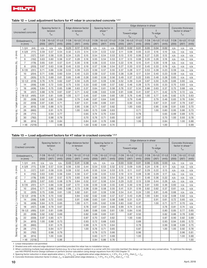
Table 12 mdash Load adjustment factors for 7 rebar in uncracked concrete 123
7Uncracked concrete
Spacing factor in tension
fAN
Edge distance factor in tension
fRN
Spacing factor in shear 4
fAV
Edge distance in shearConcrete thickness
factor in shear 5
fHV
Toward edge
fRV
To edge
fRV
Embedment hefin (mm)
7-78 10-12 17-12 7-78 10-12 17-12 7-78 10-12 17-12 7-78 10-12 17-12 7-78 10-12 17-12 7-78 10-12 17-12(200) (267) (445) (200) (267) (445) (200) (267) (445) (200) (267) (445) (200) (267) (445) (200) (267) (445)
Spac
ing
(s)
edg
e di
stan
ce (c
a) c
oncr
ete
thic
knes
s (h
) - i
n (m
m)
1-34 (44) na na na 023 017 010 na na na 003 002 001 005 004 002 na na na4-38 (111) 059 057 054 032 023 014 054 053 052 011 008 005 022 016 010 na na na
5 (127) 061 058 055 034 025 015 054 054 053 013 010 006 027 020 012 na na na6 (152) 063 060 056 037 028 016 055 054 053 017 013 008 035 026 016 na na na7 (178) 065 061 057 041 030 018 056 055 054 022 016 010 041 030 018 na na na8 (203) 067 063 058 045 033 019 057 056 054 027 020 012 045 033 019 na na na
9-78 (251) 071 066 059 053 039 023 059 057 055 037 028 017 053 039 023 059 na na10 (254) 071 066 060 054 040 023 059 057 055 038 028 017 054 040 023 059 na na12 (305) 075 069 061 065 048 028 060 059 056 049 037 022 065 048 028 065 na na
12-12 (318) 076 070 062 067 050 029 061 059 056 052 039 024 067 050 029 066 060 na14 (356) 080 072 063 075 055 033 062 060 057 062 046 028 075 055 033 070 063 na16 (406) 084 075 065 086 063 037 064 061 058 076 057 034 086 063 037 075 068 na18 (457) 088 079 067 097 071 042 066 063 059 091 068 041 097 071 042 079 072 na
19-12 (495) 091 081 069 100 077 045 067 064 060 100 076 046 100 077 045 082 075 06320 (508) 092 082 069 079 046 067 064 060 079 048 079 046 083 076 06422 (559) 097 085 071 087 051 069 066 061 092 055 087 051 087 079 06724 (610) 100 088 073 095 056 071 067 062 100 063 095 056 091 083 07026 (660) 091 075 100 060 073 069 063 071 100 060 095 086 07328 (711) 094 077 065 074 070 064 079 065 099 089 07530 (762) 098 079 070 076 071 065 087 070 100 093 07836 (914) 100 084 084 081 076 068 100 084 100 086
gt 48 (1219) 096 100 092 084 074 100 099
Table 13 mdash Load adjustment factors for 7 rebar in cracked concrete 123
7Cracked concrete
Spacing factor in tension
fAN
Edge distance factor in tension
fRN
Spacing factor in shear 4
fAV
Edge distance in shearConcrete thickness
factor in shear 5
fHV
Toward edge
fRV
To edge
fRV
Embedment hefin (mm)
7-78 10-12 17-12 7-78 10-12 17-12 7-78 10-12 17-12 7-78 10-12 17-12 7-78 10-12 17-12 7-78 10-12 17-12(200) (267) (445) (200) (267) (445) (200) (267) (445) (200) (267) (445) (200) (267) (445) (200) (267) (445)
Spac
ing
(s)
edg
e di
stan
ce (c
a) c
oncr
ete
thic
knes
s (h
) - i
n (m
m)
1-34 (44) na na na 043 041 038 na na na 003 002 001 006 005 003 na na na4-38 (111) 059 057 054 056 050 044 054 053 052 012 009 005 024 018 011 na na na
5 (127) 061 058 055 059 052 045 055 054 053 015 011 007 029 022 013 na na na6 (152) 063 060 056 064 056 047 056 055 053 019 014 009 038 029 017 na na na7 (178) 065 061 057 070 060 049 056 055 054 024 018 011 048 036 022 na na na8 (203) 067 063 058 076 064 052 057 056 054 029 022 013 059 044 026 na na na
9-78 (251) 071 066 059 087 072 056 059 058 055 040 030 018 081 060 036 060 na na10 (254) 071 066 060 088 073 056 059 058 055 041 031 018 082 062 037 061 na na12 (305) 075 069 061 100 082 061 061 059 056 054 041 024 100 081 049 066 na na
12-12 (318) 076 070 062 084 062 062 060 057 057 043 026 100 084 052 068 062 na14 (356) 080 072 063 091 066 063 061 058 068 051 031 091 061 072 065 na16 (406) 084 075 065 100 071 065 062 059 083 062 037 100 071 077 070 na18 (457) 088 079 067 076 067 064 060 099 074 045 076 081 074 na
19-12 (495) 091 081 069 080 068 065 061 100 084 050 080 085 077 06520 (508) 092 082 069 082 068 065 061 087 052 082 086 078 06622 (559) 097 085 071 087 070 067 062 100 060 087 090 082 06924 (610) 100 088 073 093 072 068 063 069 093 094 085 07226 (660) 091 075 099 074 070 064 078 099 098 089 07528 (711) 094 077 100 076 071 065 087 100 100 092 07830 (762) 098 079 078 073 066 096 096 08136 (914) 100 084 083 077 069 100 100 088
gt 48 (1219) 096 094 086 076 1001 Linear interpolation not permitted2 Shaded area with reduced edge distance is permitted provided the rebar has no installation torque3 When combining multiple load adjustment factors (eg for a four-anchor pattern in a corner with thin concrete member) the design can become very conservative To optimize the design
use Hilti PROFIS Anchor Design software or perform anchor calculation using design equations from ACI 318 Chapter 174 Spacing factor reduction in shear applicable when ca lt 3hef ƒAV is applicable when edge distance ca lt 3hef If ca ge 3hef then ƒAV = ƒAN 5 Concrete thickness reduction factor in shear ƒHV is applicable when edge distance ca lt 3hef If ca ge 3hef then ƒHV = 10
HIT-HY 100 Technical Supplement
11April 2018
Table 14 mdash Load adjustment factors for 8 rebar in uncracked concrete 123
8Uncracked concrete
Spacing factor in tension
fAN
Edge distance factor in tension
fRN
Spacing factor in shear 4
fAV
Edge distance in shearConcrete thickness
factor in shear 5
fHV
Toward edge
fRV
To edge
fRV
Embedment hefin (mm)
9 12 20 9 12 20 9 12 20 9 12 20 9 12 20 9 12 20 (229) (305) (508) (229) (305) (508) (229) (305) (508) (229) (305) (508) (229) (305) (508) (229) (305) (508)
Spac
ing
(s)
edg
e di
stan
ce (c
a) c
oncr
ete
thic
knes
s (h
) - i
n (m
m)
1-34 (44) na na na 023 017 010 na na na 002 002 001 005 003 002 na na na5 (127) 059 057 054 032 023 014 054 053 052 011 008 005 022 015 009 na na na6 (152) 061 058 055 035 026 015 055 054 053 014 010 006 029 020 012 na na na7 (178) 063 060 056 038 028 016 055 054 053 018 013 008 036 025 015 na na na8 (203) 065 061 057 041 030 018 056 055 053 022 015 009 041 030 018 na na na9 (229) 067 063 058 045 033 019 057 055 054 026 018 011 045 033 019 na na na10 (254) 069 064 058 048 036 021 058 056 054 031 022 013 048 036 021 na na na
11-14 (286) 071 066 059 053 039 023 059 057 055 037 026 016 053 039 023 058 na na12 (305) 072 067 060 057 042 024 059 057 055 040 028 017 057 042 024 060 na na14 (356) 076 069 062 066 049 029 061 058 056 051 036 022 066 049 029 065 na na
14-14 (362) 076 070 062 067 050 029 061 059 056 052 037 022 067 050 029 066 059 na16 (406) 080 072 063 076 056 033 062 060 057 062 044 026 076 056 033 070 062 na18 (457) 083 075 065 085 063 037 064 061 058 074 052 031 085 063 037 074 066 na20 (508) 087 078 067 095 070 041 065 062 059 087 061 037 095 070 041 078 069 na22 (559) 091 081 068 100 076 045 067 063 059 100 071 042 100 076 045 082 073 na
22-14 (565) 091 081 069 077 045 067 063 060 072 043 077 045 082 073 06224 (610) 094 083 070 083 049 068 064 060 081 048 083 049 085 076 06426 (660) 098 086 072 090 053 070 066 061 091 054 090 053 089 079 06728 (711) 100 089 073 097 057 071 067 062 100 061 097 057 092 082 06930 (762) 092 075 100 061 073 068 063 068 100 061 095 085 07236 (914) 100 080 073 077 072 065 089 073 100 093 078
gt 48 (1219) 090 098 086 079 071 100 098 100 091
Table 15 mdash Load adjustment factors for 8 rebar in cracked concrete 123
8Cracked concrete
Spacing factor in tension
fAN
Edge distance factor in tension
fRN
Spacing factor in shear 4
fAV
Edge distance in shearConcrete thickness
factor in shear 5
fHV
Toward edge
fRV
To edge
fRV
Embedment hefin (mm)
9 12 20 9 12 20 9 12 20 9 12 20 9 12 20 9 12 20 (229) (305) (508) (229) (305) (508) (229) (305) (508) (229) (305) (508) (229) (305) (508) (229) (305) (508)
Spac
ing
(s)
edg
e di
stan
ce (c
a) c
oncr
ete
thic
knes
s (h
) - i
n (m
m)
1-34 (44) na na na 042 040 038 na na na 002 002 001 005 003 002 na na na5 (127) 059 057 054 056 050 044 054 053 052 011 008 005 022 017 010 na na na6 (152) 061 058 055 060 053 046 055 054 053 015 011 007 029 022 013 na na na7 (178) 063 060 056 065 057 047 055 054 053 018 014 008 037 028 017 na na na8 (203) 065 061 057 070 060 049 056 055 054 023 017 010 045 034 020 na na na9 (229) 067 063 058 075 064 051 057 056 054 027 020 012 054 040 024 na na na10 (254) 069 064 058 080 067 053 058 056 055 031 024 014 063 047 028 na na na
11-14 (286) 071 066 059 087 072 056 059 057 055 038 028 017 075 056 034 059 na na12 (305) 072 067 060 091 075 057 059 058 055 041 031 019 083 062 037 061 na na14 (356) 076 069 062 100 083 062 061 059 056 052 039 023 100 078 047 066 na na
14-14 (362) 076 070 062 084 062 061 059 056 054 040 024 080 048 066 060 na16 (406) 080 072 063 091 066 062 060 057 064 048 029 091 057 070 064 na18 (457) 083 075 065 100 070 064 061 058 076 057 034 100 068 075 068 na20 (508) 087 078 067 075 065 063 059 089 067 040 075 079 071 na22 (559) 091 081 068 080 067 064 060 100 077 046 080 082 075 na
22-14 (565) 091 081 069 080 067 064 060 078 047 080 083 075 06324 (610) 094 083 070 085 069 065 061 088 053 085 086 078 06626 (660) 098 086 072 090 070 067 062 099 059 090 090 081 06928 (711) 100 089 073 095 072 068 063 100 066 095 093 084 07130 (762) 092 075 100 073 069 064 074 100 096 087 07436 (914) 100 080 078 073 066 097 100 096 081
gt 48 (1219) 090 087 081 072 100 100 0931 Linear interpolation not permitted2 Shaded area with reduced edge distance is permitted provided the rebar has no installation torque3 When combining multiple load adjustment factors (eg for a four-anchor pattern in a corner with thin concrete member) the design can become very conservative To optimize the design
use Hilti PROFIS Anchor Design software or perform anchor calculation using design equations from ACI 318 Chapter 174 Spacing factor reduction in shear applicable when ca lt 3hef ƒAV is applicable when edge distance ca lt 3hef If ca ge 3hef then ƒAV = ƒAN 5 Concrete thickness reduction factor in shear ƒHV is applicable when edge distance ca lt 3hef If ca ge 3hef then ƒHV = 10
12 April 2018
Table 16 mdash Load adjustment factors for 9 rebar in uncracked concrete 123
9Uncracked concrete
Spacing factor in tension
fAN
Edge distance factor in tension
fRN
Spacing factor in shear 4
fAV
Edge distance in shearConcrete thickness
factor in shear 5
fHV
Toward edge
fRV
To edge
fRV
Embedment hefin (mm)
10-18 13-12 22-12 10-18 13-12 22-12 10-18 13-12 22-12 10-18 13-12 22-12 10-18 13-12 22-12 10-18 13-12 22-12(257) (343) (572) (257) (343) (572) (257) (343) (572) (257) (343) (572) (257) (343) (572) (257) (343) (572)
Spac
ing
(s)
edg
e di
stan
ce (c
a) c
oncr
ete
thic
knes
s (h
) - i
n (m
m)
1-34 (44) na na na 022 016 010 na na na 002 001 001 004 003 002 na na na5-58 (143) 059 057 054 032 024 014 054 053 052 011 008 005 022 015 009 na na na
6 (152) 060 057 054 033 024 014 054 053 052 012 008 005 024 017 010 na na na7 (178) 062 059 055 036 026 015 055 054 053 015 011 006 030 021 013 na na na8 (203) 063 060 056 039 029 017 055 054 053 018 013 008 037 026 016 na na na9 (229) 065 061 057 042 031 018 056 055 053 022 016 009 042 031 018 na na na10 (254) 066 062 057 045 033 019 057 055 054 026 018 011 045 033 019 na na na12 (305) 070 065 059 052 038 022 058 056 055 034 024 014 052 038 022 na na na
12-78 (327) 071 066 060 056 041 024 059 057 055 038 027 016 056 041 024 059 na na14 (356) 073 067 060 061 045 026 059 057 055 043 030 018 061 045 026 061 na na16 (406) 076 070 062 069 051 030 061 059 056 052 037 022 069 051 030 066 na na
16-14 (413) 077 070 062 070 052 030 061 059 056 053 038 023 070 052 030 066 059 na18 (457) 080 072 063 078 057 033 062 060 057 062 044 026 078 057 033 070 062 na20 (508) 083 075 065 087 064 037 063 061 058 073 051 031 087 064 037 073 065 na22 (559) 086 077 066 095 070 041 065 062 058 084 059 036 095 070 041 077 069 na24 (610) 090 080 068 100 076 045 066 063 059 096 067 040 100 076 045 080 072 na
25-14 (641) 092 081 069 080 047 067 063 060 100 073 044 080 047 083 073 06226 (660) 093 082 069 083 048 068 064 060 076 046 083 048 084 075 06328 (711) 096 085 071 089 052 069 065 061 085 051 089 052 087 077 06530 (762) 099 087 072 095 056 070 066 061 094 057 095 056 090 080 06836 (914) 100 094 077 100 067 074 069 064 100 074 100 067 099 088 074
gt 48 (1219) 100 086 100 089 082 076 068 100 089 100 100 085
Table 17 mdash Load adjustment factors for 9 rebar in cracked concrete 123
9Cracked concrete
Spacing factor in tension
fAN
Edge distance factor in tension
fRN
Spacing factor in shear 4
fAV
Edge distance in shearConcrete thickness
factor in shear 5
fHV
Toward edge
fRV
To edge
fRV
Embedment hefin (mm)
10-18 13-12 22-12 10-18 13-12 22-12 10-18 13-12 22-12 10-18 13-12 22-12 10-18 13-12 22-12 10-18 13-12 22-12(257) (343) (572) (257) (343) (572) (257) (343) (572) (257) (343) (572) (257) (343) (572) (257) (343) (572)
Spac
ing
(s)
edg
e di
stan
ce (c
a) c
oncr
ete
thic
knes
s (h
) - i
n (m
m)
1-34 (44) na na na 041 039 038 na na na 002 001 001 004 003 002 na na na5-58 (143) 059 057 054 056 050 044 054 053 052 011 008 005 022 016 009 na na na
6 (152) 060 057 054 057 051 044 054 053 052 012 009 005 024 017 010 na na na7 (178) 062 059 055 061 054 046 055 054 053 015 011 007 030 022 013 na na na8 (203) 063 060 056 065 057 048 055 054 053 019 013 008 037 027 016 na na na9 (229) 065 061 057 070 060 049 056 055 053 022 016 010 044 032 019 na na na10 (254) 066 062 057 074 063 051 057 055 054 026 019 011 052 037 022 na na na12 (305) 070 065 059 084 070 055 058 057 055 034 025 015 068 049 029 na na na
12-78 (327) 071 066 060 088 073 056 059 057 055 038 027 016 076 054 033 059 na na14 (356) 073 067 060 094 077 058 060 058 055 043 031 019 086 062 037 062 na na16 (406) 076 070 062 100 084 062 061 059 056 053 038 023 100 075 045 066 na na
16-14 (413) 077 070 062 085 063 061 059 056 054 039 023 077 046 066 059 na18 (457) 080 072 063 091 066 062 060 057 063 045 027 090 054 070 063 na20 (508) 083 075 065 099 070 064 061 058 073 053 032 099 063 074 066 na22 (559) 086 077 066 100 074 065 062 059 085 061 036 100 073 077 069 na24 (610) 090 080 068 078 066 063 059 097 069 042 078 081 072 na
25-14 (641) 092 081 069 081 067 064 060 100 075 045 081 083 074 06326 (660) 093 082 069 082 068 064 060 078 047 082 084 075 06328 (711) 096 085 071 087 069 065 061 087 052 087 087 078 06630 (762) 099 087 072 091 070 066 062 097 058 091 090 081 06836 (914) 100 094 077 100 074 070 064 100 076 100 099 088 075
gt 48 (1219) 100 086 083 076 069 100 100 100 0861 Linear interpolation not permitted2 Shaded area with reduced edge distance is permitted provided the rebar has no installation torque3 When combining multiple load adjustment factors (eg for a four-anchor pattern in a corner with thin concrete member) the design can become very conservative To optimize the design
use Hilti PROFIS Anchor Design software or perform anchor calculation using design equations from ACI 318 Chapter 174 Spacing factor reduction in shear applicable when ca lt 3hef ƒAV is applicable when edge distance ca lt 3hef If ca ge 3hef then ƒAV = ƒAN 5 Concrete thickness reduction factor in shear ƒHV is applicable when edge distance ca lt 3hef If ca ge 3hef then ƒHV = 10
HIT-HY 100 Technical Supplement
13April 2018
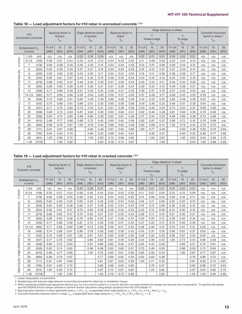
Table 18 mdash Load adjustment factors for 10 rebar in uncracked concrete 123
10Uncracked concrete
Spacing factor in tension
fAN
Edge distance factor in tension
fRN
Spacing factor in shear 4
fAV
Edge distance in shearConcrete thickness
factor in shear 5
fHV
Toward edge
fRV
To edge
fRV
Embedment hefin (mm)
11-14 15 25 11-14 15 25 11-14 15 25 11-14 15 25 11-14 15 25 11-14 15 25 (286) (381) (635) (286) (381) (635) (286) (381) (635) (286) (381) (635) (286) (381) (635) (286) (381) (635)
Spac
ing
(s)
edg
e di
stan
ce (c
a) c
oncr
ete
thic
knes
s (h
) - i
n (m
m) 1-34 (44) na na na 022 016 009 na na na 002 001 001 003 002 001 na na na
6-14 (159) 059 057 054 033 024 014 054 053 052 011 008 005 022 016 010 na na na7 (178) 060 058 055 035 025 015 054 053 052 013 010 006 026 019 012 na na na8 (203) 062 059 055 037 027 016 055 054 053 016 012 007 031 023 014 na na na9 (229) 063 060 056 040 030 017 055 054 053 019 014 008 038 028 017 na na na10 (254) 065 061 057 043 032 019 056 055 054 022 016 010 043 032 019 na na na11 (279) 066 062 057 046 034 020 057 055 054 025 019 011 046 034 020 na na na12 (305) 068 063 058 049 036 021 057 056 054 029 022 013 049 036 021 na na na14 (356) 071 066 059 057 042 024 059 057 055 036 027 016 057 042 024 na na na
14-14 (362) 071 066 060 058 043 025 059 057 055 037 028 017 058 043 025 059 na na16 (406) 074 068 061 065 048 028 060 058 056 045 033 020 065 048 028 062 na na17 (432) 075 069 061 069 051 030 060 058 056 049 036 022 069 051 030 064 na na18 (457) 077 070 062 073 054 031 061 059 056 053 040 024 073 054 031 066 060 na20 (508) 080 072 063 081 060 035 062 060 057 062 046 028 081 060 035 070 063 na22 (559) 083 074 065 089 066 038 063 061 058 072 054 032 089 066 038 073 066 na24 (610) 086 077 066 098 072 042 065 062 059 082 061 037 098 072 042 076 069 na26 (660) 089 079 067 100 078 045 066 063 059 092 069 041 100 078 045 079 072 na28 (711) 091 081 069 084 049 067 064 060 100 077 046 084 049 082 075 06330 (762) 094 083 070 090 052 068 065 061 085 051 090 052 085 077 06536 (914) 100 090 074 100 063 072 068 063 100 067 100 063 094 085 072
gt 48 (1219) 100 082 084 079 074 067 100 084 100 098 083
Table 19 mdash Load adjustment factors for 10 rebar in cracked concrete 123
10Cracked concrete
Spacing factor in tension
fAN
Edge distance factor in tension
fRN
Spacing factor in shear 4
fAV
Edge distance in shearConcrete thickness
factor in shear 5
fHV
Toward edge
fRV
To edge
fRV
Embedment hefin (mm)
11-14 15 25 11-14 15 25 11-14 15 25 11-14 15 25 11-14 15 25 11-14 15 25 (286) (381) (635) (286) (381) (635) (286) (381) (635) (286) (381) (635) (286) (381) (635) (286) (381) (635)
Spac
ing
(s)
edg
e di
stan
ce (c
a) c
oncr
ete
thic
knes
s (h
) - i
n (m
m) 1-34 (44) na na na 040 039 037 na na na 002 001 001 003 002 001 na na na
6-14 (159) 059 057 054 056 050 044 054 053 052 011 007 004 022 015 009 na na na7 (178) 060 058 055 058 052 045 054 053 052 013 009 005 026 018 011 na na na8 (203) 062 059 055 062 055 046 055 054 053 016 011 006 032 022 013 na na na9 (229) 063 060 056 066 057 048 055 054 053 019 013 008 038 026 015 na na na10 (254) 065 061 057 070 060 049 056 055 053 022 015 009 044 030 018 na na na11 (279) 066 062 057 074 063 051 057 055 054 026 017 010 051 035 021 na na na12 (305) 068 063 058 078 066 053 057 056 054 029 020 012 058 040 024 na na na14 (356) 071 066 059 087 072 056 059 057 055 037 025 015 073 050 030 na na na
14-14 (362) 071 066 060 088 073 056 059 057 055 038 026 015 075 051 031 059 na na16 (406) 074 068 061 096 078 059 060 058 055 045 031 018 090 061 037 063 na na17 (432) 075 069 061 100 081 061 060 058 056 049 033 020 098 067 040 064 na na18 (457) 077 070 062 085 062 061 059 056 054 036 022 100 073 044 066 058 na20 (508) 080 072 063 091 066 062 059 057 063 043 026 085 051 070 061 na22 (559) 083 074 065 098 069 063 060 057 072 049 030 098 059 073 064 na24 (610) 086 077 066 100 073 065 061 058 082 056 034 100 067 077 067 na26 (660) 089 079 067 077 066 062 059 093 063 038 076 080 070 na28 (711) 091 081 069 081 067 063 059 100 071 042 081 083 073 06130 (762) 094 083 070 085 068 064 060 078 047 085 086 075 06436 (914) 100 090 074 097 072 067 062 100 062 097 094 082 070
gt 48 (1219) 100 082 100 079 073 066 095 100 100 095 0801 Linear interpolation not permitted2 Shaded area with reduced edge distance is permitted provided the rebar has no installation torque3 When combining multiple load adjustment factors (eg for a four-anchor pattern in a corner with thin concrete member) the design can become very conservative To optimize the design
use Hilti PROFIS Anchor Design software or perform anchor calculation using design equations from ACI 318 Chapter 174 Spacing factor reduction in shear applicable when ca lt 3hef ƒAV is applicable when edge distance ca lt 3hef If ca ge 3hef then ƒAV = ƒAN 5 Concrete thickness reduction factor in shear ƒHV is applicable when edge distance ca lt 3hef If ca ge 3hef then ƒHV = 10
14 April 2018
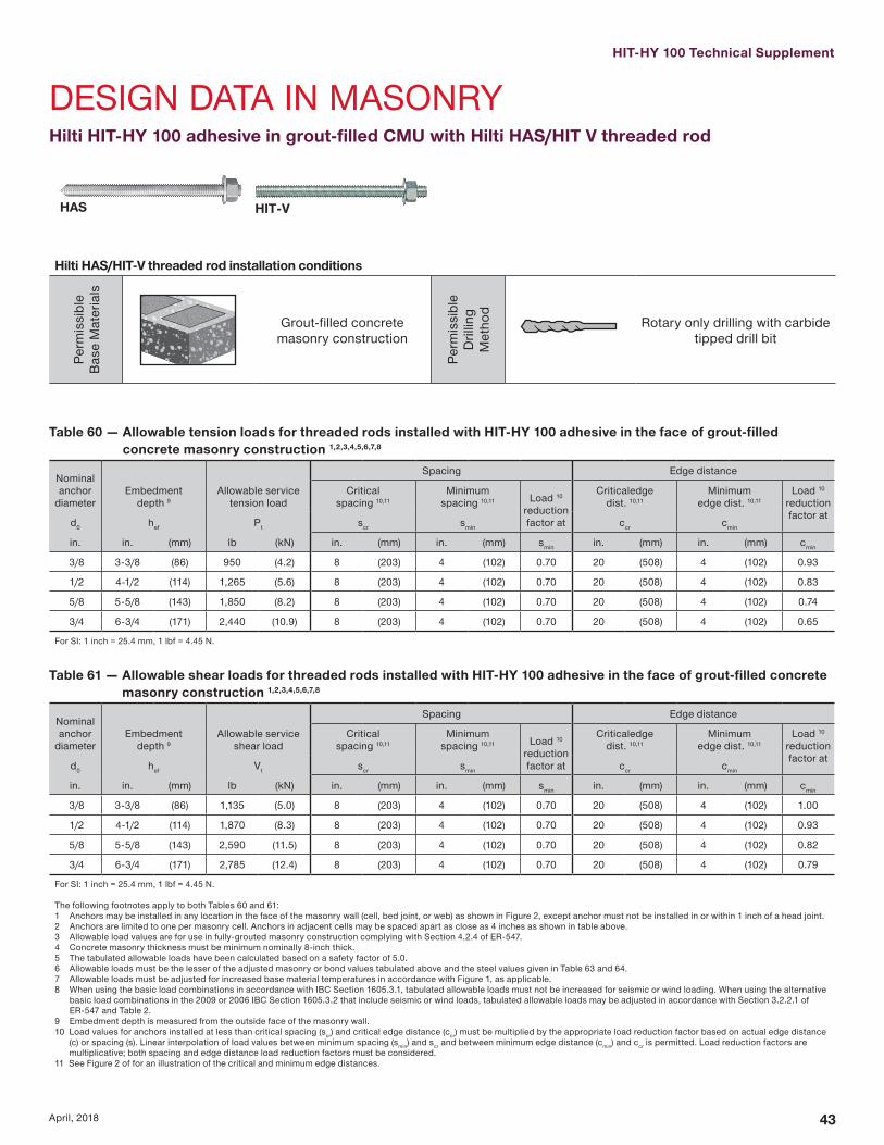
Hilti HIT-HY 100 adhesive with Hilti HAS threaded rod
HIT-VHAS
Hilti HAS HIT-V threaded rod installation conditions
Perm
issi
ble
Bas
e M
ater
ials
Uncracked concrete
DryConcrete
Perm
issi
ble
Dril
ling
Met
hod
Hammer Drilling with Carbide Tipped
Drill Bit
Cracked concrete
Water Saturated Concrete
Hollow Drill Bit
Hilti HASHIT-V threaded rod installation specifications
Nominal Rod
Diameter
Drill Bit Diameter
Embedment Depth Range
Maximum Installation
Torque
Minimum Base Material
Thickness
din (mm)
d0in
hefin (mm)
Tmaxft-lb (Nm)
hminin (mm)
38716
2-38 ndash 7-12 15hef + 1-14 (hef + 30)
(95) (60 ndash 191) (20)12
916 2-34 ndash 10 30
(127) (70 ndash 254) (41)58
343-18 ndash 12-12 60
hef + 2d0
(159) (79 ndash 318) (81)34
783-12 ndash 15 100
(191) (89 ndash 381) (136)78
13-12 ndash 17-12 125
(222) (89 ndash 445) (169)1
1-184 ndash 20 150
(254) (102 ndash 508) (203)1-14
1-385 ndash 25 200
(318) (127 ndash 635) (271)
min
max
df HASHIT-V 38 12 58 34 78 1 1-14
df1 12 58 1316 1516 1-18 1-14 1-12
df2 716 916 1116 1316 1516 1-18 1-38 Use two washers
HIT-HY 100 Technical Supplement
15April 2018
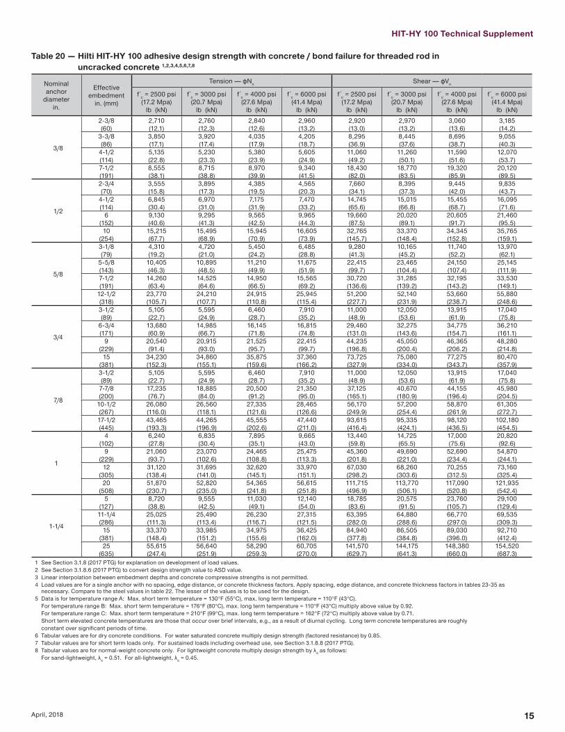
Table 20 mdash Hilti HIT-HY 100 adhesive design strength with concrete bond failure for threaded rod in uncracked concrete 12345678
Nominal anchor
diameterin
Effective embedment
in (mm)
Tension mdash ϕNn Shear mdash ϕVn
f´c = 2500 psi(172 Mpa)
lb (kN)
f´c = 3000 psi(207 Mpa)
lb (kN)
f´c = 4000 psi(276 Mpa)
lb (kN)
f´c = 6000 psi(414 Mpa)
lb (kN)
f´c = 2500 psi(172 Mpa)
lb (kN)
f´c = 3000 psi(207 Mpa)
lb (kN)
f´c = 4000 psi(276 Mpa)
lb (kN)
f´c = 6000 psi(414 Mpa)
lb (kN)
38
2-38 2710 2760 2840 2960 2920 2970 3060 3185(60) (121) (123) (126) (132) (130) (132) (136) (142)
3-38 3850 3920 4035 4205 8295 8445 8695 9055(86) (171) (174) (179) (187) (369) (376) (387) (403)
4-12 5135 5230 5380 5605 11060 11260 11590 12070(114) (228) (233) (239) (249) (492) (501) (516) (537)7-12 8555 8715 8970 9340 18430 18770 19320 20120(191) (381) (388) (399) (415) (820) (835) (859) (895)
12
2-34 3555 3895 4385 4565 7660 8395 9445 9835(70) (158) (173) (195) (203) (341) (373) (420) (437)
4-12 6845 6970 7175 7470 14745 15015 15455 16095(114) (304) (310) (319) (332) (656) (668) (687) (716)
6 9130 9295 9565 9965 19660 20020 20605 21460(152) (406) (413) (425) (443) (875) (891) (917) (955)10 15215 15495 15945 16605 32765 33370 34345 35765
(254) (677) (689) (709) (739) (1457) (1484) (1528) (1591)
58
3-18 4310 4720 5450 6485 9280 10165 11740 13970(79) (192) (210) (242) (288) (413) (452) (522) (621)
5-58 10405 10895 11210 11675 22415 23465 24150 25145(143) (463) (485) (499) (519) (997) (1044) (1074) (1119)7-12 14260 14525 14950 15565 30720 31285 32195 33530(191) (634) (646) (665) (692) (1366) (1392) (1432) (1491)
12-12 23770 24210 24915 25945 51200 52140 53660 55880(318) (1057) (1077) (1108) (1154) (2277) (2319) (2387) (2486)
34
3-12 5105 5595 6460 7910 11000 12050 13915 17040(89) (227) (249) (287) (352) (489) (536) (619) (758)
6-34 13680 14985 16145 16815 29460 32275 34775 36210(171) (609) (667) (718) (748) (1310) (1436) (1547) (1611)
9 20540 20915 21525 22415 44235 45050 46365 48280(229) (914) (930) (957) (997) (1968) (2004) (2062) (2148)
15 34230 34860 35875 37360 73725 75080 77275 80470(381) (1523) (1551) (1596) (1662) (3279) (3340) (3437) (3579)
78
3-12 5105 5595 6460 7910 11000 12050 13915 17040(89) (227) (249) (287) (352) (489) (536) (619) (758)7-78 17235 18885 20500 21350 37125 40670 44155 45980(200) (767) (840) (912) (950) (1651) (1809) (1964) (2045)
10-12 26080 26560 27335 28465 56170 57200 58870 61305(267) (1160) (1181) (1216) (1266) (2499) (2544) (2619) (2727)17-12 43465 44265 45555 47440 93615 95335 98120 102180(445) (1933) (1969) (2026) (2110) (4164) (4241) (4365) (4545)
1
4 6240 6835 7895 9665 13440 14725 17000 20820(102) (278) (304) (351) (430) (598) (655) (756) (926)
9 21060 23070 24465 25475 45360 49690 52690 54870(229) (937) (1026) (1088) (1133) (2018) (2210) (2344) (2441)
12 31120 31695 32620 33970 67030 68260 70255 73160(305) (1384) (1410) (1451) (1511) (2982) (3036) (3125) (3254)
20 51870 52820 54365 56615 111715 113770 117090 121935(508) (2307) (2350) (2418) (2518) (4969) (5061) (5208) (5424)
1-14
5 8720 9555 11030 12140 18785 20575 23760 29100(127) (388) (425) (491) (540) (836) (915) (1057) (1294)11-14 25025 25490 26230 27315 63395 64880 66770 69535(286) (1113) (1134) (1167) (1215) (2820) (2886) (2970) (3093)
15 33370 33985 34975 36425 84940 86505 89030 92710(381) (1484) (1512) (1556) (1620) (3778) (3848) (3960) (4124)25 55615 56640 58290 60705 141570 144175 148380 154520
(635) (2474) (2519) (2593) (2700) (6297) (6413) (6600) (6873)1 See Section 318 (2017 PTG) for explanation on development of load values2 See Section 3186 (2017 PTG) to convert design strength value to ASD value3 Linear interpolation between embedment depths and concrete compressive strengths is not permitted4 Load values are for a single anchor with no spacing edge distance or concrete thickness factors Apply spacing edge distance and concrete thickness factors in tables 23-35 as
necessary Compare to the steel values in table 22 The lesser of the values is to be used for the design5 Data is for temperature range A Max short term temperature = 130degF (55degC) max long term temperature = 110degF (43degC) For temperature range B Max short term temperature = 176degF (80degC) max long term temperature = 110degF (43degC) multiply above value by 092 For temperature range C Max short term temperature = 210degF (99degC) max long term temperature = 162degF (72degC) multiply above value by 071 Short term elevated concrete temperatures are those that occur over brief intervals eg as a result of diurnal cycling Long term concrete temperatures are roughly constant over significant periods of time6 Tabular values are for dry concrete conditions For water saturated concrete multiply design strength (factored resistance) by 0857 Tabular values are for short term loads only For sustained loads including overhead use see Section 3188 (2017 PTG)8 Tabular values are for normal-weight concrete only For lightweight concrete multiply design strength by λa as follows For sand-lightweight λa = 051 For all-lightweight λa = 045
16 April 2018
Table 21 mdash Hilti HIT-HY 100 adhesive design strength with concrete bond failure for threaded rod in cracked concrete 123456789
Nominal anchor
diameterin
Effective embedment
in (mm)
Tension mdash ϕNn Shear mdash ϕVn
f´c = 2500 psi(172 Mpa)
lb (kN)
f´c = 3000 psi(207 Mpa)
lb (kN)
f´c = 4000 psi(276 Mpa)
lb (kN)
f´c = 6000 psi(414 Mpa)
lb (kN)
f´c = 2500 psi(172 Mpa)
lb (kN)
f´c = 3000 psi(207 Mpa)
lb (kN)
f´c = 4000 psi(276 Mpa)
lb (kN)
f´c = 6000 psi(414 Mpa)
lb (kN)
38
2-38 1120 1140 1170 1220 1205 1225 1260 1315(60) (50) (51) (52) (54) (54) (54) (56) (58)
3-38 1590 1620 1665 1735 3425 3485 3590 3735(86) (71) (72) (74) (77) (152) (155) (160) (166)
4-12 2120 2160 2220 2315 4565 4650 4785 4980(114) (94) (96) (99) (103) (203) (207) (213) (222)7-12 3530 3595 3700 3855 7610 7750 7975 8305(191) (157) (160) (165) (171) (339) (345) (355) (369)
12
2-34 1880 1915 1970 2055 4050 4125 4245 4425(70) (84) (85) (88) (91) (180) (183) (189) (197)
4-12 3080 3135 3225 3360 6630 6750 6950 7235(114) (137) (139) (143) (149) (295) (300) (309) (322)
6 4105 4180 4300 4480 8840 9005 9265 9650(152) (183) (186) (191) (199) (393) (401) (412) (429)10 6840 6965 7170 7465 14735 15005 15445 16080
(254) (304) (310) (319) (332) (655) (667) (687) (715)
58
3-18 2890 2945 3030 3155 6230 6345 6530 6800(79) (129) (131) (135) (140) (277) (282) (290) (302)
5-58 5205 5300 5455 5680 11210 11415 11750 12235(143) (232) (236) (243) (253) (499) (508) (523) (544)7-12 6940 7065 7275 7575 14945 15220 15665 16315(191) (309) (314) (324) (337) (665) (677) (697) (726)
12-12 11565 11780 12125 12625 24910 25370 26110 27190(318) (514) (524) (539) (562) (1108) (1129) (1161) (1209)
34
3-12 3620 3965 4355 4535 7790 8535 9380 9765(89) (161) (176) (194) (202) (347) (380) (417) (434)
6-34 8010 8160 8395 8745 17255 17575 18085 18835(171) (356) (363) (373) (389) (768) (782) (804) (838)
9 10680 10880 11195 11660 23010 23430 24115 25115(229) (475) (484) (498) (519) (1024) (1042) (1073) (1117)
15 17805 18130 18660 19435 38345 39055 40190 41855(381) (792) (806) (830) (865) (1706) (1737) (1788) (1862)
78
3-12 3620 3965 4575 5325 7790 8535 9855 11470(89) (161) (176) (204) (237) (347) (380) (438) (510)7-78 10975 11175 11505 11980 23640 24075 24775 25800(200) (488) (497) (512) (533) (1052) (1071) (1102) (1148)
10-12 14635 14905 15340 15975 31520 32100 33035 34405(267) (651) (663) (682) (711) (1402) (1428) (1469) (1530)17-12 24390 24840 25565 26620 52530 53500 55060 57340(445) (1085) (1105) (1137) (1184) (2337) (2380) (2449) (2551)
1
4 4420 4840 5590 6845 9520 10430 12040 14750(102) (197) (215) (249) (304) (423) (464) (536) (656)
9 14520 14785 15220 15845 31270 31845 32775 34135(229) (646) (658) (677) (705) (1391) (1417) (1458) (1518)
12 19360 19715 20290 21130 41695 42460 43700 45510(305) (861) (877) (903) (940) (1855) (1889) (1944) (2024)
32265 32860 33815 35215 69490 70770 72835 75850(508) (1435) (1462) (1504) (1566) (3091) (3148) (3240) (3374)
1 See Section 318 (2017 PTG) for explanation on development of load values2 See Section 3186 (2017 PTG) to convert design strength value to ASD value3 Linear interpolation between embedment depths and concrete compressive strengths is not permitted4 Load values are for a single anchor with no spacing edge distance or concrete thickness factors Apply spacing edge distance and concrete thickness factors in tables 23-35 as
necessary Compare to the steel values in table 22 The lesser of the values is to be used for the design5 Data is for temperature range A Max short term temperature = 130degF (55degC) max long term temperature = 110degF (43degC) For temperature range B Max short term temperature = 176degF (80degC) max long term temperature = 110degF (43degC) multiply above value by 092 For temperature range C Max short term temperature = 210degF (99degC) max long term temperature = 162degF (72degC) multiply above value by 071 Short term elevated concrete temperatures are those that occur over brief intervals eg as a result of diurnal cycling Long term concrete temperatures are roughly constant over significant periods of time6 Tabular values are for dry concrete conditions For water saturated concrete multiply design strength (factored resistance) by 0857 Tabular values are for short term loads only For sustained loads including overhead use see Section 3188 (2017 PTG)8 Tabular values are for normal-weight concrete only For lightweight concrete multiply design strength by λa as follows For sand-lightweight λa = 051 For all-lightweight λa = 045 9 Tabular values are for static loads only For seismic loads multiply cracked concrete tabular values in tension and shear by αseis = 075
HIT-HY 100 Technical Supplement
17April 2018
Table 22 mdash Steel design strength HAS and HIT-V anchor threaded rods for use with ACI 318-14 Ch 17
Nominal anchor
diameterin
HIT-VASTM A307 Grade A 4
HAS-EISO 898 Class 58 4
HAS-E-B and HAS-E-B HDGASTM A193 B7 and
ASTM F 1554 Gr 105 5
Tensile1
ϕNsalb (kN)
Shear2
ϕVsalb (kN)
Seismic Shear3
ϕVsaeqlb (kN)
Tensile1
ϕNsalb (kN)
Shear2
ϕVsalb (kN)
Seismic Shear3
ϕVsaeqlb (kN)
Tensile1
ϕNsalb (kN)
Shear2
ϕVsalb (kN)
Seismic Shear3
ϕVsaeqlb (kN)
38 3025 1675 1175 3655 2020 1415 7265 3780 2645(135) (75) (52) (163) (90) (63) (323) (168) (118)
12 5535 3065 2145 6690 3705 2595 13300 6915 4840(246) (136) (95) (295) (165) (115) (592) (308) (215)
58 8815 4880 3415 10650 5900 4130 21190 11020 7715(392) (216) (152) (474) (262) (184) (943) (490) (343)
34 13045 7225 5060 15765 8730 6110 31360 16305 11415(580) (321) (225) (701) (388) (272) (1395) (725) (508)
78 - - - 21755 12050 8435 43285 22505 15755- - - (968) (536) (375) (1925) (1001) (701)
123620 13085 9160 28540 15805 11065 56785 29525 20670(1051) (582) (407) (1270) (703) (492) (2526) (1313) (919)
1-14- - - 45670 25295 17705 90850 47240 33070- - - (2003) (1125) (788) (4041) (2101) (1471)
1 Tensile = ϕ AseN futa as noted in ACI 318-14 174122 Shear = ϕ 060 AseV futa as noted in ACI 318-14 17512b3 Seismic Shear = αVseis ϕVsa Reduction factor for seismic shear only See ACI 318 for additional information on seismic applications 4 HIT-V and HAS-E threaded rods are considered brittle steel elements HIT-V does not comply with elongation requirements of ASTM A307 Grade A steel HAS-E does not comply with
elongation requirements of ISO 898-15 HAS-E-B and HAS-E-B HDG rods are considered ductile steel elements
Table 22 (Continued) mdash Steel design strength for Hilti HAS threaded rods for use with ACI 318 Chapter 17
Nominal anchor
diameterin
HAS-V HAS-V HDGASTM F1554 Gr 36 46
HAS-E HAS-E HDGASTM F1554 Gr 55 46
HAS-B and HAS-B HDGASTM A193 B7 and
ASTM F 1554 Gr 105 46
HAS-R Stainless SteelASTM F593 (38-in to 1-in) 5
ASTM A193 (1-18-in to 1-14-in)4
Tensile1
ϕNsalb (kN)
Shear2
ϕVsalb (kN)
Seismic Shear3
ϕVsaeqlb (kN)
Tensile1
ϕNsalb (kN)
Shear2
ϕVsalb (kN)
Seismic Shear3
ϕVsaeqlb (kN)
Tensile1
ϕNsalb (kN)
Shear2
ϕVsalb (kN)
Seismic Shear3
ϕVsaeqlb (kN)
Tensile1
ϕNsalb (kN)
Shear6
ϕVsalb (kN)
Seismic Shear3
ϕVsaeqlb (kN)
38 3370 1750 1050 4360 2270 1590 7270 3780 2645 5040 2790 1955(150) (78) (47) (194) (101) (71) (323) (168) (118) (224) (124) (87)
12 6175 3210 1925 7985 4150 2905 13305 6920 4845 9225 5110 3575(275) (143) (86) (355) (185) (129) (592) (308) (216) (410) (227) (159)
58 9835 5110 3065 12715 6610 4625 21190 11020 7715 14690 8135 5695(437) (227) (136) (566) (294) (206) (943) (490) (343) (653) (362) (253)
34 14550 7565 4540 18820 9785 6850 31360 16310 11415 18485 10235 7165(647) (337) (202) (837) (435) (305) (1395) (726) (508) (822) (455) (319)
78 20085 10445 6265 25975 13505 9455 43285 22510 15755 25510 14125 9890(893) (465) (279) (1155) (601) (421) (1925) (1001) (701) (1135) (628) (440)
126350 13700 8220 34075 17720 12405 56785 29530 20670 33465 18535 12975(1172) (609) (366) (1516) (788) (552) (2526) (1314) (919) (1489) (824) (577)
1-1442160 21920 13150 54515 28345 19840 90855 47245 33070 41430 21545 12925(1875) (975) (585) (2425) (1261) (883) (4041) (2102) (1471) (1843) (958) (575)
1 Tensile = ϕ AseN futa as noted in ACI 318-14 174122 Shear = ϕ 060 AseV futa as noted in ACI 318-14 17512b3 Seismic Shear = αVseis ϕVsa Reduction factor for seismic shear only See ACI 318 for additional information on seismic applications 4 HAS-V HAS-E HAS-B and HAS-R (Class 1 1-18-in to 1-14-in) threaded rods are considered ductile steel elements (included HDG rods)5 HAS-E-B and HAS-E-B HDG rods are
considered ductile steel elements 5 HAS-R (CW1 and CW2 38-in to 1-in) threaded rods are considered brittle steel elements (including HDG rods)6 38-inch dia threaded rods are not included in the ASTM F1554 standard Hilti 38-inch dia HAS-V HAS-E and HAS-E-B (incl HDG) threaded rods meet the chemical composition and
mechanical property requirements of ASTM F1554
18 April 2018
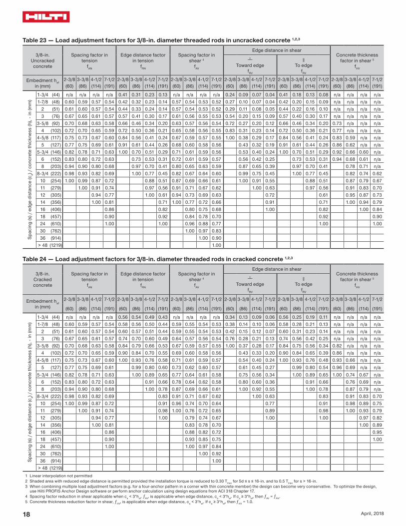
Table 23 mdash Load adjustment factors for 38-in diameter threaded rods in uncracked concrete 123
38-inUncracked concrete
Spacing factor in tension
fAN
Edge distance factor in tension
fRN
Spacing factor in shear 4
fAV
Edge distance in shearConcrete thickness
factor in shear 5
fHV
Toward edge
fRV
To edge
fRV
Embedment hefin (mm)
2-38 3-38 4-12 7-12 2-38 3-38 4-12 7-12 2-38 3-38 4-12 7-12 2-38 3-38 4-12 7-12 2-38 3-38 4-12 7-12 2-38 3-38 4-12 7-12(60) (86) (114) (191) (60) (86) (114) (191) (60) (86) (114) (191) (60) (86) (114) (191) (60) (86) (114) (191) (60) (86) (114) (191)
Spac
ing
(s)
edg
e di
stan
ce (c
a) c
oncr
ete
thic
knes
s (h
) - i
n (m
m)
1-34 (44) na na na na 041 031 023 013 na na na na 024 009 007 004 041 018 013 008 na na na na1-78 (48) 060 059 057 054 042 032 023 014 057 054 053 052 027 010 007 004 042 020 015 009 na na na na
2 (51) 061 060 057 054 044 033 024 014 057 054 053 052 029 011 008 005 044 022 016 010 na na na na3 (76) 067 065 061 057 057 041 030 017 061 056 055 053 054 020 015 009 057 040 030 017 na na na na
3-58 (92) 070 068 063 058 066 046 034 020 063 057 056 054 072 027 020 012 066 046 034 020 073 na na na4 (102) 072 070 065 059 072 050 036 021 065 058 056 055 083 031 023 014 072 050 036 021 077 na na na
4-58 (117) 075 073 067 060 084 056 041 024 067 059 057 055 100 038 029 017 084 056 041 024 083 059 na na5 (127) 077 075 069 061 091 061 044 026 068 060 058 056 043 032 019 091 061 044 026 086 062 na na
5-34 (146) 082 078 071 063 100 070 051 029 071 061 059 056 053 040 024 100 070 051 029 092 066 060 na6 (152) 083 080 072 063 073 053 031 072 061 059 057 056 042 025 073 053 031 094 068 061 na8 (203) 094 090 080 068 097 070 041 080 065 063 059 087 065 039 097 070 041 078 071 na
8-34 (222) 098 093 082 069 100 077 045 082 067 064 060 099 075 045 100 077 045 082 074 06210 (254) 100 099 087 072 088 051 087 069 066 061 100 091 055 088 051 087 079 06711 (279) 100 091 074 097 056 091 071 067 062 100 063 097 056 091 083 07012 (305) 094 077 100 061 094 073 069 063 072 061 095 087 07314 (356) 100 081 071 100 077 072 066 091 071 100 094 07916 (406) 086 082 080 075 068 100 082 100 08418 (457) 090 092 084 078 070 092 09024 (610) 100 100 096 088 077 100 10030 (762) 100 097 08336 (914) 100 090
gt 48 (1219) 100
Table 24 mdash Load adjustment factors for 38-in diameter threaded rods in cracked concrete 123
38-inCracked concrete
Spacing factor in tension
fAN
Edge distance factor in tension
fRN
Spacing factor in shear 4
fAV
Edge distance in shearConcrete thickness
factor in shear 5
fHV
Toward edge
fRV
To edge
fRV
Embedment hefin (mm)
2-38 3-38 4-12 7-12 2-38 3-38 4-12 7-12 2-38 3-38 4-12 7-12 2-38 3-38 4-12 7-12 2-38 3-38 4-12 7-12 2-38 3-38 4-12 7-12
(60) (86) (114) (191) (60) (86) (114) (191) (60) (86) (114) (191) (60) (86) (114) (191) (60) (86) (114) (191) (60) (86) (114) (191)
Spac
ing
(s)
edg
e di
stan
ce (c
a) c
oncr
ete
thic
knes
s (h
) - i
n (m
m)
1-34 (44) na na na na 056 054 049 043 na na na na 034 013 009 006 056 025 019 011 na na na na1-78 (48) 060 059 057 054 058 056 050 044 059 055 054 053 038 014 010 006 058 028 021 013 na na na na
2 (51) 061 060 057 054 060 057 051 044 059 055 054 053 042 015 012 007 060 031 023 014 na na na na3 (76) 067 065 061 057 074 070 060 049 064 057 056 054 076 028 021 013 074 056 042 025 na na na na
3-58 (92) 070 068 063 058 084 079 066 053 067 059 057 055 100 037 028 017 084 075 056 034 082 na na na4 (102) 072 070 065 059 090 084 070 055 069 060 058 056 043 033 020 090 084 065 039 086 na na na
4-58 (117) 075 073 067 060 100 093 076 058 071 061 059 057 054 040 024 100 093 076 048 093 066 na na5 (127) 077 075 069 061 099 080 060 073 062 060 057 061 045 027 099 080 054 096 069 na na
5-34 (146) 082 078 071 063 100 089 065 077 064 061 058 075 056 034 100 089 065 100 074 067 na6 (152) 083 080 072 063 091 066 078 064 062 058 080 060 036 091 066 076 069 na8 (203) 094 090 080 068 100 078 087 069 066 061 100 092 055 100 078 087 079 na
8-34 (222) 098 093 082 069 083 091 071 067 062 100 063 083 091 083 07010 (254) 100 099 087 072 091 096 074 070 064 077 091 098 089 07511 (279) 100 091 074 098 100 076 072 065 089 098 100 093 07912 (305) 094 077 100 079 074 067 100 100 097 08214 (356) 100 081 083 078 070 100 08916 (406) 086 088 082 072 09518 (457) 090 093 085 075 10024 (610) 100 100 097 08430 (762) 100 09236 (914) 100
gt 48 (1219)1 Linear interpolation not permitted2 Shaded area with reduced edge distance is permitted provided the installation torque is reduced to 030 Tmax for 5d le s le 16-in and to 05 Tmax for s gt 16-in3 When combining multiple load adjustment factors (eg for a four-anchor pattern in a corner with thin concrete member) the design can become very conservative To optimize the design
use Hilti PROFIS Anchor Design software or perform anchor calculation using design equations from ACI 318 Chapter 174 Spacing factor reduction in shear applicable when ca lt 3hef ƒAV is applicable when edge distance ca lt 3hef If ca ge 3hef then ƒAV = ƒAN 5 Concrete thickness reduction factor in shear ƒHV is applicable when edge distance ca lt 3hef If ca ge 3hef then ƒHV = 10
HIT-HY 100 Technical Supplement
19April 2018
Table 25 mdash Load adjustment factors for 12-in diameter threaded rods in uncracked concrete 123
12-inUncracked concrete
Spacing factor in tension
fAN
Edge distance factor in tension
fRN
Spacing factor in shear 4
fAV
Edge distance in shearConcrete thickness
factor in shear 5
fHV
Toward edge
fRV
To edge
fRV
Embedment hefin (mm)
2-34 4-12 6 10 2-34 4-12 6 10 2-34 4-12 6 10 2-34 4-12 6 10 2-34 4-12 6 10 2-34 4-12 6 10 (70) (114) (152) (254) (70) (114) (152) (254) (70) (114) (152) (254) (70) (114) (152) (254) (70) (114) (152) (254) (70) (114) (152) (254)
Spac
ing
(s)
edg
e di
stan
ce (c
a) c
oncr
ete
thic
knes
s (h
) - i
n (m
m) 1-34 (44) na na na na 037 027 020 012 na na na na 010 006 004 003 021 012 009 005 na na na na
2-12 (64) 060 059 057 054 045 031 023 013 055 054 053 052 018 010 007 004 035 020 015 009 na na na na3 (76) 062 061 058 055 050 034 025 015 056 054 054 053 023 013 010 006 046 026 019 012 na na na na4 (102) 067 065 061 057 061 040 029 017 058 056 055 053 036 020 015 009 061 040 029 017 058 na na na
5-34 (146) 074 071 066 060 088 051 038 022 062 058 057 055 061 034 026 016 088 051 038 022 069 057 na na6 (152) 075 072 067 060 092 053 039 023 063 059 057 055 065 037 028 017 092 053 039 023 071 058 na na7 (178) 079 076 069 062 100 062 045 026 065 060 058 056 082 046 035 021 100 062 045 026 077 063 na na
7-14 (184) 080 077 070 062 064 047 027 065 060 059 056 087 049 037 022 064 047 027 078 064 058 na8 (203) 083 080 072 063 070 052 030 067 061 059 057 100 056 042 025 070 052 030 082 068 061 na10 (254) 091 087 078 067 088 065 038 071 064 062 058 079 059 036 088 065 038 092 075 069 na
11-14 (286) 096 092 081 069 099 073 043 074 066 063 059 094 071 042 099 073 043 097 080 073 06112 (305) 099 094 083 070 100 078 045 075 067 064 060 100 078 047 100 078 045 100 083 075 06314 (356) 100 100 089 073 090 053 079 070 066 062 098 059 090 053 089 081 06816 (406) 094 077 100 061 084 073 069 063 100 072 100 061 095 087 07318 (457) 100 080 068 088 076 071 065 086 068 100 092 07820 (508) 083 076 092 078 074 067 100 076 097 08222 (559) 087 083 096 081 076 068 083 100 08624 (610) 090 091 100 084 078 070 091 09030 (762) 100 100 093 085 075 100 10036 (914) 100 092 080
gt 48 (1219) 100 090
Table 26 mdash Load adjustment factors for 12-in diameter threaded rods in cracked concrete 123
12-inCracked concrete
Spacing factor in tension
fAN
Edge distance factor in tension
fRN
Spacing factor in shear 4
fAV
Edge distance in shearConcrete thickness
factor in shear 5
fHV
Toward edge
fRV
To edge
fRV
Embedment hefin (mm)
2-34 4-12 6 10 2-34 4-12 6 10 2-34 4-12 6 10 2-34 4-12 6 10 2-34 4-12 6 10 2-34 4-12 6 10 (70) (114) (152) (254) (70) (114) (152) (254) (70) (114) (152) (254) (70) (114) (152) (254) (70) (114) (152) (254) (70) (114) (152) (254)
Spac
ing
(s)
edg
e di
stan
ce (c
a) c
oncr
ete
thic
knes
s (h
) - i
n (m
m) 1-34 (44) na na na na 051 049 045 041 na na na na 012 008 006 004 024 016 012 007 na na na na
2-12 (64) 060 059 057 054 058 056 050 044 056 054 054 053 021 014 010 006 042 027 021 012 na na na na3 (76) 062 061 058 055 063 060 053 046 057 055 054 053 027 018 014 008 055 036 027 016 na na na na4 (102) 067 065 061 057 074 070 060 049 059 057 056 054 042 028 021 013 074 056 042 025 061 na na na
5-34 (146) 074 071 066 060 096 089 073 056 064 060 058 056 073 048 036 022 096 089 072 043 073 064 na na6 (152) 075 072 067 060 099 091 075 057 064 061 059 056 077 051 038 023 099 091 075 046 075 065 na na7 (178) 079 076 069 062 100 100 083 062 066 062 060 057 098 064 048 029 100 100 083 058 081 071 na na
7-14 (184) 080 077 070 062 085 063 067 063 061 058 100 068 051 031 085 061 082 072 065 na8 (203) 083 080 072 063 091 066 069 064 062 058 079 059 035 091 066 087 075 068 na10 (254) 091 087 078 067 100 075 073 068 065 060 100 082 049 100 075 097 084 077 na
11-14 (286) 096 092 081 069 081 076 070 067 062 098 059 081 100 089 081 06812 (305) 099 094 083 070 085 078 071 068 063 100 065 085 092 084 07114 (356) 100 100 089 073 095 083 075 071 065 082 095 100 091 07616 (406) 094 077 100 088 078 073 067 100 100 100 097 08218 (457) 100 080 092 082 076 069 100 100 08720 (508) 083 097 086 079 071 09122 (559) 087 100 089 082 073 09624 (610) 090 093 085 075 10030 (762) 100 100 094 08136 (914) 100 088
gt 48 (1219) 1001 Linear interpolation not permitted2 Shaded area with reduced edge distance is permitted provided the installation torque is reduced to 030 Tmax for 5d le s le 16-in and to 05 Tmax for s gt 16-in3 When combining multiple load adjustment factors (eg for a four-anchor pattern in a corner with thin concrete member) the design can become very conservative To optimize the design
use Hilti PROFIS Anchor Design software or perform anchor calculation using design equations from ACI 318 Chapter 174 Spacing factor reduction in shear applicable when ca lt 3hef ƒAV is applicable when edge distance ca lt 3hef If ca ge 3hef then ƒAV = ƒAN 5 Concrete thickness reduction factor in shear ƒHV is applicable when edge distance ca lt 3hef If ca ge 3hef then ƒHV = 10
20 April 2018
Table 27 mdash Load adjustment factors for 58-in diameter threaded rods in uncracked concrete 123
58-inUncracked concrete
Spacing factor in tension
fAN
Edge distance factor in tension
fRN
Spacing factor in shear 4
fAV
Edge distance in shearConcrete thickness
factor in shear 5
fHV
Toward edge
fRV
To edge
fRV
Embedment hefin (mm)
3-18 5-58 7-12 12-12 3-18 5-58 7-12 12-12 3-18 5-58 7-12 12-12 3-18 5-58 7-12 12-12 3-18 5-58 7-12 12-12 3-18 5-58 7-12 12-12(79) (143) (191) (318) (79) (143) (191) (318) (79) (143) (191) (318) (79) (143) (191) (318) (79) (143) (191) (318) (79) (143) (191) (318)
Spac
ing
(s)
edg
e di
stan
ce (c
a) c
oncr
ete
thic
knes
s (h
) - i
n (m
m)
1-34 (44) na na na na 035 025 019 011 na na na na 009 004 003 002 019 009 006 004 na na na na3-18 (79) 060 059 057 054 048 031 023 013 056 054 053 052 022 010 007 004 045 020 015 009 na na na na
4 (102) 063 062 059 055 056 035 026 015 058 055 054 053 032 015 011 006 056 029 021 013 na na na na4-58 (117) 065 064 060 056 063 038 028 016 059 055 054 053 040 018 013 008 063 037 027 016 060 na na na
5 (127) 067 065 061 057 068 040 029 017 060 056 055 053 045 021 015 009 068 040 029 017 063 na na na6 (152) 070 068 063 058 081 045 033 019 062 057 056 054 059 027 020 012 081 045 033 019 069 na na na
7-18 (181) 073 071 066 060 095 051 037 022 064 058 057 055 077 035 025 015 095 051 037 022 075 058 na na8 (203) 076 074 068 061 100 056 041 024 066 059 058 055 091 042 030 018 100 056 041 024 079 061 na na10 (254) 083 080 072 063 070 052 030 070 062 059 057 100 058 042 025 070 052 030 089 068 061 na11 (279) 086 083 074 065 077 057 033 072 063 060 057 067 049 029 077 057 033 093 071 064 na12 (305) 090 086 077 066 084 062 036 074 064 061 058 076 056 033 084 062 036 097 075 067 na14 (356) 096 092 081 069 098 072 042 077 066 063 059 096 070 042 098 072 042 100 081 073 06116 (406) 100 097 086 071 100 083 048 081 069 065 061 100 086 051 100 083 048 086 078 06518 (457) 100 090 074 093 054 085 071 067 062 100 061 093 054 091 082 06920 (508) 094 077 100 060 089 073 069 063 072 100 060 096 087 07322 (559) 099 079 066 093 076 071 065 083 066 100 091 07724 (610) 100 082 072 097 078 073 066 094 072 095 08026 (660) 085 079 100 080 074 067 100 079 099 08328 (711) 087 085 083 076 069 085 100 08730 (762) 090 091 085 078 070 091 09036 (914) 098 100 092 084 074 100 098
gt 48 (1219) 100 100 095 082 100
Table 28 mdash Load adjustment factors for 58-in diameter threaded rods in cracked concrete 123
58-inCracked concrete
Spacing factor in tension
fAN
Edge distance factor in tension
fRN
Spacing factor in shear 4
fAV
Edge distance in shearConcrete thickness
factor in shear 5
fHV
Toward edge
fRV
To edge
fRV
Embedment hefin (mm)
3-18 5-58 7-12 12-12 3-18 5-58 7-12 12-12 3-18 5-58 7-12 12-12 3-18 5-58 7-12 12-12 3-18 5-58 7-12 12-12 3-18 5-58 7-12 12-12(79) (143) (191) (318) (79) (143) (191) (318) (79) (143) (191) (318) (79) (143) (191) (318) (79) (143) (191) (318) (79) (143) (191) (318)
Spac
ing
(s)
edg
e di
stan
ce (c
a) c
oncr
ete
thic
knes
s (h
) - i
n (m
m)
1-34 (44) na na na na 047 046 043 040 na na na na 009 006 004 003 019 011 009 005 na na na na3-18 (79) 060 059 057 054 058 056 050 044 056 054 054 053 023 014 010 006 045 027 020 012 na na na na
4 (102) 063 062 059 055 066 062 055 046 058 056 055 053 033 020 015 009 065 040 030 018 na na na na4-58 (117) 065 064 060 056 071 067 058 048 059 057 055 054 040 025 018 011 071 049 037 022 060 na na na
5 (127) 067 065 061 057 074 070 060 049 060 057 056 054 045 028 021 012 074 055 041 025 063 na na na6 (152) 070 068 063 058 084 078 066 053 062 059 057 055 060 036 027 016 084 073 054 033 069 na na na
7-18 (181) 073 071 066 060 095 088 073 056 064 060 058 056 077 047 035 021 095 088 070 042 075 063 na na8 (203) 076 074 068 061 100 096 078 059 066 061 059 057 092 056 042 025 100 096 078 050 079 067 na na10 (254) 083 080 072 063 100 091 066 070 064 062 058 100 078 059 035 100 091 066 089 075 068 na11 (279) 086 083 074 065 098 070 072 066 063 059 090 068 041 098 070 093 079 072 na12 (305) 090 086 077 066 100 073 074 067 064 060 100 077 046 100 073 097 082 075 na14 (356) 096 092 081 069 081 078 070 066 062 097 058 081 100 089 081 06816 (406) 100 097 086 071 089 082 073 069 063 100 071 089 095 086 07318 (457) 100 090 074 097 086 075 071 065 085 097 100 092 07720 (508) 094 077 100 089 078 073 067 099 100 097 08122 (559) 099 079 093 081 076 068 100 100 08524 (610) 100 082 097 084 078 070 08926 (660) 085 100 087 080 072 09328 (711) 087 090 083 073 09630 (762) 090 092 085 075 10036 (914) 098 100 092 080 100
gt 48 (1219) 100 100 0901 Linear interpolation not permitted2 Shaded area with reduced edge distance is permitted provided the installation torque is reduced to 030 Tmax for 5d le s le 16-in and to 05 Tmax for s gt 16-in3 When combining multiple load adjustment factors (eg for a four-anchor pattern in a corner with thin concrete member) the design can become very conservative To optimize the design
use Hilti PROFIS Anchor Design software or perform anchor calculation using design equations from ACI 318 Chapter 174 Spacing factor reduction in shear applicable when ca lt 3hef ƒAV is applicable when edge distance ca lt 3hef If ca ge 3hef then ƒAV = ƒAN 5 Concrete thickness reduction factor in shear ƒHV is applicable when edge distance ca lt 3hef If ca ge 3hef then ƒHV = 10
HIT-HY 100 Technical Supplement
21April 2018
Table 29 mdash Load adjustment factors for 34-in diameter threaded rods in uncracked concrete 123
34-inUncracked concrete
Spacing factor in tension
fAN
Edge distance factor in tension
fRN
Spacing factor in shear 4
fAV
Edge distance in shearConcrete thickness
factor in shear 5
fHV
Toward edge
fRV
To edge
fRV
Embedment hefin (mm)
3-12 6-34 9 15 3-12 6-34 9 15 3-12 6-34 9 15 3-12 6-34 9 15 3-12 6-34 9 15 3-12 6-34 9 15 (89) (171) (229) (381) (89) (171) (229) (381) (89) (171) (229) (381) (89) (171) (229) (381) (89) (171) (229) (381) (89) (171) (229) (381)
Spac
ing
(s)
edg
e di
stan
ce (c
a) c
oncr
ete
thic
knes
s (h
) - i
n (m
m)
1-34 (44) na na na na 035 024 018 010 na na na na 009 004 002 001 017 007 005 003 na na na na3-34 (95) 060 059 057 054 052 031 023 013 057 054 053 052 027 011 007 004 052 022 015 009 na na na na
4 (102) 061 060 057 054 054 032 023 014 057 054 053 052 029 012 008 005 054 024 016 010 na na na na5-14 (133) 064 063 060 056 066 037 027 016 060 055 054 053 044 018 012 007 066 036 024 014 062 na na na
6 (152) 067 065 061 057 074 040 029 017 061 056 055 053 054 022 015 009 074 040 029 017 067 na na na8 (203) 072 070 065 059 090 048 035 021 065 058 056 054 083 034 023 014 090 048 035 021 077 na na na
8-12 (216) 073 071 066 059 095 050 037 022 066 059 057 055 091 037 025 015 095 050 037 022 079 059 na na10 (254) 077 075 069 061 100 058 043 025 068 060 058 056 100 047 032 019 100 058 043 025 086 064 na na
10-34 (273) 080 077 070 062 063 046 027 070 061 058 056 053 035 021 063 046 027 089 066 058 na12 (305) 083 080 072 063 070 052 030 072 062 059 057 062 041 025 070 052 030 094 070 061 na14 (356) 088 085 076 066 082 060 035 076 064 061 058 078 052 031 082 060 035 100 075 066 na16 (406) 094 090 080 068 093 069 040 080 066 062 059 096 064 038 093 069 040 081 070 na
16-34 (425) 096 091 081 069 098 072 042 081 067 063 059 100 068 041 098 072 042 082 072 06118 (457) 099 094 083 070 100 077 045 083 068 064 060 076 046 100 077 045 085 075 06320 (508) 100 099 087 072 086 050 087 070 065 061 089 054 086 050 090 079 06622 (559) 100 091 074 094 055 091 072 067 062 100 062 094 055 094 082 07024 (610) 094 077 100 060 094 074 069 063 070 100 060 099 086 07326 (660) 098 079 065 098 076 070 064 079 065 100 090 07628 (711) 100 081 070 100 078 072 065 089 070 093 07830 (762) 083 075 080 073 067 098 075 096 08136 (914) 090 091 086 078 070 100 091 100 089
gt 48 (1219) 100 100 099 087 076 100 100
Table 30 mdash Load adjustment factors for 34-in diameter threaded rods in cracked concrete 123
34-inCracked concrete
Spacing factor in tension
fAN
Edge distance factor in tension
fRN
Spacing factor in shear 4
fAV
Edge distance in shearConcrete thickness
factor in shear 5
fHV
Toward edge
fRV
To edge
fRV
Embedment hefin (mm)
3-12 6-34 9 15 3-12 6-34 9 15 3-12 6-34 9 15 3-12 6-34 9 15 3-12 6-34 9 15 3-12 6-34 9 15 (89) (171) (229) (381) (89) (171) (229) (381) (89) (171) (229) (381) (89) (171) (229) (381) (89) (171) (229) (381) (89) (171) (229) (381)
Spac
ing
(s)
edg
e di
stan
ce (c
a) c
oncr
ete
thic
knes
s (h
) - i
n (m
m)
1-34 (44) na na na na 045 044 042 039 na na na na 009 004 003 002 017 009 006 004 na na na na3-34 (95) 060 059 057 054 058 056 050 044 057 054 054 053 027 013 010 006 054 027 020 012 na na na na
4 (102) 061 060 057 054 060 057 051 044 057 055 054 053 030 015 011 007 059 029 022 013 na na na na5-14 (133) 064 063 060 056 069 065 057 048 060 056 055 054 045 022 017 010 069 044 033 020 062 na na na
6 (152) 067 065 061 057 074 070 060 049 061 057 056 054 055 027 020 012 074 054 040 024 067 na na na8 (203) 072 070 065 059 090 084 070 055 065 059 058 055 084 041 031 019 090 083 062 037 077 na na na
8-12 (216) 073 071 066 059 095 088 072 056 066 060 058 056 092 045 034 020 095 088 068 041 079 063 na na10 (254) 077 075 069 061 100 099 080 060 069 062 060 057 100 058 043 026 100 099 080 052 086 068 na na
10-34 (273) 080 077 070 062 100 084 062 070 062 060 057 064 048 029 100 084 058 089 071 064 na12 (305) 083 080 072 063 091 066 072 064 061 058 076 057 034 091 066 094 075 068 na14 (356) 088 085 076 066 100 072 076 066 063 060 096 072 043 100 072 100 080 073 na16 (406) 094 090 080 068 078 080 069 065 061 100 088 053 078 086 078 na
16-34 (425) 096 091 081 069 081 081 069 066 061 094 056 081 088 080 06718 (457) 099 094 083 070 085 083 071 067 062 100 063 085 091 083 07020 (508) 100 099 087 072 091 087 073 069 064 074 091 096 087 07422 (559) 100 091 074 098 091 075 071 065 085 098 100 092 07724 (610) 094 077 100 095 078 073 066 097 100 096 08126 (660) 098 079 098 080 075 068 100 100 08428 (711) 100 081 100 082 077 069 100 08730 (762) 083 085 079 070 09036 (914) 090 092 084 074 099
gt 48 (1219) 100 100 096 083 1001 Linear interpolation not permitted2 Shaded area with reduced edge distance is permitted provided the installation torque is reduced to 030 Tmax for 5d le s le 16-in and to 05 Tmax for s gt 16-in3 When combining multiple load adjustment factors (eg for a four-anchor pattern in a corner with thin concrete member) the design can become very conservative To optimize the design
use Hilti PROFIS Anchor Design software or perform anchor calculation using design equations from ACI 318 Chapter 174 Spacing factor reduction in shear applicable when ca lt 3hef ƒAV is applicable when edge distance ca lt 3hef If ca ge 3hef then ƒAV = ƒAN 5 Concrete thickness reduction factor in shear ƒHV is applicable when edge distance ca lt 3hef If ca ge 3hef then ƒHV = 10
22 April 2018
Table 31 mdash Load adjustment factors for 78-in diameter threaded rods in uncracked concrete 123
78-inUncracked concrete
Spacing factor in tension
fAN
Edge distance factor in tension
fRN
Spacing factor in shear 4
fAV
Edge distance in shearConcrete thickness
factor in shear 5
fHV
Toward edge
fRV
To edge
fRV
Embedment hefin (mm)
3-12 7-78 10-12 17-12 3-12 7-78 10-12 17-12 3-12 7-78 10-12 17-12 3-12 7-78 10-12 17-12 3-12 7-78 10-12 17-12 3-12 7-78 10-12 17-12(89) (200) (267) (445) (89) (200) (267) (445) (89) (200) (267) (445) (89) (200) (267) (445) (89) (200) (267) (445) (89) (200) (267) (445)
Spac
ing
(s)
edg
e di
stan
ce (c
a) c
oncr
ete
thic
knes
s (h
) - i
n (m
m)
1-34 (44) na na na na 039 023 017 010 na na na na 009 003 002 001 018 006 004 002 na na na na4-38 (111) 061 059 057 054 059 031 023 013 058 054 053 052 035 011 007 004 059 022 014 009 na na na na
5 (127) 062 061 058 055 063 033 024 014 060 054 053 052 043 013 009 005 063 027 018 011 na na na na5-12 (140) 063 062 059 055 066 035 026 015 060 055 054 053 050 015 010 006 066 031 020 012 065 na na na
6 (152) 065 063 060 056 069 037 027 016 061 055 054 053 057 018 012 007 069 035 023 014 068 na na na8 (203) 070 067 063 058 083 044 032 019 065 057 055 054 087 027 018 011 083 044 032 019 078 na na na
9-78 (251) 074 071 066 059 097 051 038 022 069 059 057 055 100 037 024 015 097 051 038 022 087 059 na na10 (254) 074 071 066 060 098 052 038 022 069 059 057 055 038 025 015 098 052 038 022 087 059 na na12 (305) 079 075 069 061 062 045 027 073 060 058 056 049 033 020 062 045 027 096 065 na na
12-12 (318) 080 077 070 062 064 047 028 074 061 058 056 053 035 021 064 047 028 098 066 057 na14 (356) 084 080 072 063 072 053 031 077 062 059 057 062 041 025 072 053 031 100 070 061 na16 (406) 089 084 075 065 082 060 035 080 064 061 058 076 050 030 082 060 035 075 065 na18 (457) 094 088 079 067 092 068 040 084 066 062 058 091 060 036 092 068 040 079 069 na
19-12 (495) 098 091 081 069 100 074 043 087 067 063 059 100 068 041 100 074 043 082 072 06020 (508) 099 092 082 069 076 044 088 067 063 059 070 042 076 044 083 073 06122 (559) 100 097 085 071 083 049 092 069 065 060 081 049 083 049 087 076 06424 (610) 100 088 073 091 053 096 071 066 061 092 055 091 053 091 080 06726 (660) 091 075 098 058 099 073 067 062 100 063 098 058 095 083 07028 (711) 094 077 100 062 100 074 068 063 070 100 062 099 086 07230 (762) 098 079 066 100 076 070 064 077 066 100 089 07536 (914) 100 084 080 081 074 067 100 080 097 082
gt 48 (1219) 096 100 092 082 073 100 100 095
Table 32 mdash Load adjustment factors for 78-in diameter threaded rods in cracked concrete 123
78-inCracked concrete
Spacing factor in tension
fAN
Edge distance factor in tension
fRN
Spacing factor in shear 4
fAV
Edge distance in shearConcrete thickness
factor in shear 5
fHV
Toward edge
fRV
To edge
fRV
Embedment hefin (mm)
3-12 7-78 10-12 17-12 3-12 7-78 10-12 17-12 3-12 7-78 10-12 17-12 3-12 7-78 10-12 17-12 3-12 7-78 10-12 17-12 3-12 7-78 10-12 17-12(89) (200) (267) (445) (89) (200) (267) (445) (89) (200) (267) (445) (89) (200) (267) (445) (89) (200) (267) (445) (89) (200) (267) (445)
Spac
ing
(s)
edg
e di
stan
ce (c
a) c
oncr
ete
thic
knes
s (h
) - i
n (m
m)
1-34 (44) na na na na 044 043 041 038 na na na na 009 003 002 001 018 006 005 003 na na na na4-38 (111) 061 059 057 054 059 056 050 044 058 054 053 052 036 012 009 006 059 024 018 011 na na na na
5 (127) 062 061 058 055 063 059 052 045 060 055 054 053 043 015 011 007 063 030 022 013 na na na na5-12 (140) 063 062 059 055 066 062 054 046 061 055 054 053 050 017 013 008 066 034 026 016 065 na na na
6 (152) 065 063 060 056 069 064 056 047 062 056 055 053 057 020 015 009 069 039 029 018 068 na na na8 (203) 070 067 063 058 083 076 064 052 065 058 056 054 088 030 023 014 083 060 045 027 078 na na na
9-78 (251) 074 071 066 059 097 087 072 056 069 059 058 055 100 041 031 019 097 083 062 037 087 061 na na10 (254) 074 071 066 060 098 088 073 056 069 059 058 056 042 032 019 098 084 063 038 087 061 na na12 (305) 079 075 069 061 100 082 061 073 061 059 057 055 042 025 100 082 050 096 067 na na
12-12 (318) 080 077 070 062 084 062 074 062 060 057 059 044 027 084 053 098 068 062 na14 (356) 084 080 072 063 091 066 077 063 061 058 070 052 031 091 063 100 072 066 na16 (406) 089 084 075 065 100 071 081 065 062 059 085 064 038 100 071 077 070 na18 (457) 094 088 079 067 076 084 067 064 060 100 076 046 076 082 075 na
19-12 (495) 098 091 081 069 080 087 068 065 061 086 052 080 086 078 06620 (508) 099 092 082 069 082 088 069 066 061 089 054 082 087 079 06622 (559) 100 097 085 071 087 092 071 067 062 100 062 087 091 083 07024 (610) 100 088 073 093 096 073 069 063 071 093 095 086 07326 (660) 091 075 099 100 074 070 064 080 099 099 090 07628 (711) 094 077 100 100 076 072 065 089 100 100 093 07930 (762) 098 079 078 073 067 099 096 08136 (914) 100 084 084 078 070 100 100 089
gt 48 (1219) 096 095 087 076 1001 Linear interpolation not permitted2 Shaded area with reduced edge distance is permitted provided the installation torque is reduced to 030 Tmax for 5d le s le 16-in and to 05 Tmax for s gt 16-in3 When combining multiple load adjustment factors (eg for a four-anchor pattern in a corner with thin concrete member) the design can become very conservative To optimize the design
use Hilti PROFIS Anchor Design software or perform anchor calculation using design equations from ACI 318 Chapter 174 Spacing factor reduction in shear applicable when ca lt 3hef ƒAV is applicable when edge distance ca lt 3hef If ca ge 3hef then ƒAV = ƒAN 5 Concrete thickness reduction factor in shear ƒHV is applicable when edge distance ca lt 3hef If ca ge 3hef then ƒHV = 10
HIT-HY 100 Technical Supplement
23April 2018
Table 33 mdash Load adjustment factors for 1-in diameter threaded rods in uncracked concrete 123
1-inUncracked concrete
Spacing factor in tension
fAN
Edge distance factor in tension
fRN
Spacing factor in shear 4
fAV
Edge distance in shearConcrete thickness
factor in shear 5
fHV
Toward edge
fRV
To edge
fRV
Embedment hefin (mm)
4 9 12 20 4 9 12 20 4 9 12 20 4 9 12 20 4 9 12 20 4 9 12 20 (102) (229) (305) (508) (102) (229) (305) (508) (102) (229) (305) (508) (102) (229) (305) (508) (102) (229) (305) (508) (102) (229) (305) (508)
Spac
ing
(s)
edg
e di
stan
ce (c
a) c
oncr
ete
thic
knes
s (h
) - i
n (m
m)
1-34 (44) na na na na 038 023 017 010 na na na na 008 002 002 001 015 005 003 002 na na na na5 (127) 061 059 057 054 060 032 023 014 059 054 053 052 037 011 007 004 060 022 015 009 na na na na6 (152) 063 061 058 055 066 035 025 015 060 055 054 053 048 014 010 006 066 029 019 012 na na na na
6-14 (159) 064 062 059 055 068 035 026 015 061 055 054 053 051 015 010 006 068 030 021 012 065 na na na7 (178) 066 063 060 056 072 038 028 016 062 055 054 053 061 018 012 007 072 036 024 015 069 na na na8 (203) 068 065 061 057 078 041 030 018 064 056 055 053 074 022 015 009 078 041 030 018 074 na na na10 (254) 072 069 064 058 092 048 035 021 067 058 056 054 100 031 021 013 092 048 035 021 083 na na na
11-14 (286) 075 071 066 059 100 052 039 023 069 059 057 055 037 025 015 100 052 039 023 088 059 na na12 (305) 077 072 067 060 056 041 024 071 059 057 055 040 027 016 056 041 024 091 060 na na14 (356) 081 076 069 062 065 048 028 074 061 058 056 051 035 021 065 048 028 098 065 na na
14-14 (362) 082 076 070 062 066 049 029 074 061 058 056 052 035 021 066 049 029 099 066 058 na16 (406) 086 080 072 063 074 055 032 077 062 059 057 062 042 025 074 055 032 100 070 061 na18 (457) 090 083 075 065 084 062 036 081 064 061 058 074 050 030 084 062 036 074 065 na20 (508) 095 087 078 067 093 068 040 084 065 062 058 087 059 035 093 068 040 078 068 na22 (559) 099 091 081 068 100 075 044 088 067 063 059 100 068 041 100 075 044 082 072 na
22-14 (565) 100 091 081 069 076 045 088 067 063 059 100 069 041 076 045 082 072 06124 (610) 100 094 083 070 082 048 091 068 064 060 077 046 082 048 085 075 06326 (660) 098 086 072 089 052 094 070 065 061 087 052 089 052 089 078 06628 (711) 100 089 073 096 056 098 071 066 062 098 059 096 056 092 081 06830 (762) 092 075 100 060 100 073 068 063 100 065 100 060 095 084 07136 (914) 100 080 072 077 071 065 085 072 100 092 077
gt 48 (1219) 090 096 086 078 070 100 096 100 089
Table 34 mdash Load adjustment factors for 1-in diameter threaded rods in cracked concrete 123
1-inCracked concrete
Spacing factor in tension
fAN
Edge distance factor in tension
fRN
Spacing factor in shear 4
fAV
Edge distance in shearConcrete thickness
factor in shear 5
fHV
Toward edge
fRV
To edge
fRV
Embedment hefin (mm)
4 9 12 20 4 9 12 20 4 9 12 20 4 9 12 20 4 9 12 20 4 9 12 20 (102) (229) (305) (508) (102) (229) (305) (508) (102) (229) (305) (508) (102) (229) (305) (508) (102) (229) (305) (508) (102) (229) (305) (508)
Spac
ing
(s)
edg
e di
stan
ce (c
a) c
oncr
ete
thic
knes
s (h
) - i
n (m
m)
1-34 (44) na na na na 043 042 040 038 na na na na 008 002 002 001 015 005 004 002 na na na na5 (127) 061 059 057 054 060 056 050 044 059 054 053 052 037 011 008 005 060 023 017 010 na na na na6 (152) 063 061 058 055 066 060 053 046 060 055 054 053 049 015 011 007 066 030 022 013 na na na na
6-14 (159) 064 062 059 055 068 061 054 046 061 055 054 053 052 016 012 007 068 032 024 014 066 na na na7 (178) 066 063 060 056 072 065 057 048 062 055 055 053 061 019 014 008 072 037 028 017 069 na na na8 (203) 068 065 061 057 078 070 060 049 064 056 055 054 075 023 017 010 078 046 034 021 074 na na na10 (254) 072 069 064 058 092 080 067 053 067 058 056 055 100 032 024 014 092 064 048 029 083 na na na
11-14 (286) 075 071 066 059 100 087 072 056 069 059 057 055 038 029 017 100 076 057 034 088 059 na na12 (305) 077 072 067 060 091 075 057 071 059 058 056 042 031 019 084 063 038 091 061 na na14 (356) 081 076 069 062 100 083 062 074 061 059 056 053 040 024 100 079 048 098 066 na na
14-14 (362) 082 076 070 062 084 062 075 061 059 057 054 041 024 081 049 099 067 061 na16 (406) 086 080 072 063 091 066 078 062 060 057 065 048 029 091 058 100 071 064 na18 (457) 090 083 075 065 100 070 081 064 062 058 077 058 035 100 069 075 068 na20 (508) 095 087 078 067 075 084 066 063 059 090 068 041 075 079 072 na22 (559) 099 091 081 068 080 088 067 064 060 100 078 047 080 083 075 na
22-14 (565) 100 091 081 069 080 088 067 064 060 079 048 080 083 076 06424 (610) 100 094 083 070 085 091 069 065 061 089 053 085 086 079 06626 (660) 098 086 072 090 095 070 067 062 100 060 090 090 082 06928 (711) 100 089 073 095 098 072 068 063 067 095 093 085 07230 (762) 092 075 100 100 073 069 064 075 100 097 088 07436 (914) 100 080 078 073 066 098 100 096 081
gt 48 (1219) 090 087 081 072 100 100 0941 Linear interpolation not permitted2 Shaded area with reduced edge distance is permitted provided the installation torque is reduced to 030 Tmax for 5d le s le 16-in and to 05 Tmax for s gt 16-in3 When combining multiple load adjustment factors (eg for a four-anchor pattern in a corner with thin concrete member) the design can become very conservative To optimize the design
use Hilti PROFIS Anchor Design software or perform anchor calculation using design equations from ACI 318 Chapter 174 Spacing factor reduction in shear applicable when ca lt 3hef ƒAV is applicable when edge distance ca lt 3hef If ca ge 3hef then ƒAV = ƒAN 5 Concrete thickness reduction factor in shear ƒHV is applicable when edge distance ca lt 3hef If ca ge 3hef then ƒHV = 10
24 April 2018
Table 35 mdash Load adjustment factors for 1-14-in diameter threaded rods in uncracked concrete 123
1-14-inUncracked concrete
Spacing factor in tension
fAN
Edge distance factor in tension
fRN
Spacing factor in shear 4
fAV
Edge distance in shearConcrete thickness
factor in shear 5
fHV
Toward edge
fRV
To edge
fRV
Embedment hefin (mm)
5 11-14 15 25 5 11-14 15 25 5 11-14 15 25 5 11-14 15 25 5 11-14 15 25 5 11-14 15 25 (127) (286) (381) (635) (127) (286) (381) (635) (127) (286) (381) (635) (127) (286) (381) (635) (127) (286) (381) (635) (127) (286) (381) (635)
Spac
ing
(s)
edg
e di
stan
ce (c
a) c
oncr
ete
thic
knes
s (h
) - i
n (m
m)
1-34 (44) na na na na 037 022 016 009 na na na na 005 002 001 001 011 003 002 001 na na na na6-14 (159) 062 059 057 054 063 032 024 014 059 054 053 052 037 011 008 005 063 022 016 010 na na na na
7 (178) 064 060 058 055 067 034 025 015 060 054 054 053 044 013 010 006 067 026 019 012 na na na na8 (203) 066 062 059 055 073 037 027 016 061 055 054 053 053 016 012 007 073 032 024 014 066 na na na9 (229) 068 063 060 056 078 040 029 017 062 056 055 053 063 019 014 008 078 038 028 017 070 na na na10 (254) 070 065 061 057 084 043 032 019 064 056 055 054 074 022 016 010 084 043 032 019 074 na na na11 (279) 072 066 062 057 090 046 034 020 065 057 056 054 086 025 019 011 090 046 034 020 078 na na na12 (305) 074 068 063 058 096 049 036 021 066 057 056 054 098 029 022 013 096 049 036 021 081 na na na13 (330) 076 069 064 059 100 053 039 023 068 058 057 055 100 033 024 015 100 053 039 023 084 na na na14 (356) 078 071 066 059 057 042 024 069 059 057 055 036 027 016 057 042 024 088 058 na na
14-14 (362) 078 071 066 060 058 042 025 070 059 057 055 037 028 017 058 042 025 088 059 na na15 (381) 080 072 067 060 061 045 026 071 059 058 055 040 030 018 061 045 026 091 060 na na16 (406) 082 074 068 061 065 048 028 072 060 058 056 045 033 020 065 048 028 094 062 na na17 (432) 084 075 069 061 069 051 030 073 060 059 056 049 036 022 069 051 030 096 064 na na18 (457) 086 077 070 062 073 054 031 075 061 059 056 053 040 024 073 054 031 099 066 060 na20 (508) 090 080 072 063 081 059 035 077 062 060 057 062 046 028 081 059 035 100 070 063 na22 (559) 094 083 074 065 089 065 038 080 063 061 058 072 054 032 089 065 038 073 066 na24 (610) 098 086 077 066 097 071 042 083 065 062 059 082 061 037 097 071 042 076 069 na26 (660) 100 089 079 067 100 077 045 086 066 063 059 092 069 041 100 077 045 080 072 na28 (711) 092 081 069 083 049 088 067 064 060 100 077 046 083 049 083 075 06330 (762) 094 083 070 089 052 091 068 065 061 085 051 089 052 085 077 06536 (914) 100 090 074 100 063 099 072 068 063 100 067 100 063 094 085 072
gt 48 (1219) 100 082 084 100 079 074 067 100 084 100 098 0831 Linear interpolation not permitted2 Shaded area with reduced edge distance is permitted provided the installation torque is reduced to 030 Tmax for 5d le s le 16-in and to 05 Tmax for s gt 16-in3 When combining multiple load adjustment factors (eg for a four-anchor pattern in a corner with thin concrete member) the design can become very conservative To optimize the design
use Hilti PROFIS Anchor Design software or perform anchor calculation using design equations from ACI 318 Chapter 174 Spacing factor reduction in shear applicable when ca lt 3hef ƒAV is applicable when edge distance ca lt 3hef If ca ge 3hef then ƒAV = ƒAN 5 Concrete thickness reduction factor in shear ƒHV is applicable when edge distance ca lt 3hef If ca ge 3hef then ƒHV = 10
HIT-HY 100 Technical Supplement
25April 2018
Hilti HIT-HY 100 adhesive with Hilti HIS-N and HIS-RN internally threaded insert
Hilti HIS-N and HIS-RN internally threaded insert installation conditions
Perm
issi
ble
Bas
e M
ater
ials
Uncracked concrete
DryConcrete
Perm
issi
ble
Dril
ling
Met
hod
Hammer Drilling with Carbide Tipped
Drill Bit
Water Saturated Concrete
Hollow Drill Bit
Hilti HIS-N and HIS-RN installation specificationsInternal Nominal
Rod Diameter
InsertExternal Diameter
DrillBit Diameter
Embedment Depth
BoltEmbedment
Maximum Installation
Torque
Minimum Base Material
Thickness
din (mm)
Din (mm)
d0in
hefin (mm)
hsin
Tmaxft-lb (Nm)
hminin (mm)
38 0651116
4-3838 ndash 1516
15 59(95) (165) (110) (20) (150)12 081
785
12 ndash 1-31630 67
(127) (205) (125) (41) (170)58 100
1-186-34
58 ndash 1-1260 91
(159) (254) (170) (81) (230)34 109
1-148-18
34 ndash 1-78100 106
(191) (276) (205) (136) (270)
min
max
26 April 2018
Table 36 mdash Hilti HIT-HY 100 adhesive design strength with concrete bond failure for Hilti HIS-N and HIS-RN internally threaded inserts in uncracked concrete 12345678
Thread size
Effective Embedment
Depth in (mm)
Tension mdash ФNn Shear mdash ФVn
f´c = 2500 psi (172 MPa)
lb (kN)
f´c = 3000 psi (207 MPa)
lb (kN)
f´c = 4000 psi (276 MPa)
lb (kN)
f´c = 6000 psi (414 MPa)
lb (kN)
f´c = 2500 psi(172 MPa)
lb (kN)
f´c = 3000 psi(207 MPa)
lb (kN)
f´c = 4000 psi(276 MPa)
lb (kN)
f´c = 6000 psi(414 MPa)
lb (kN)
38-16 UNC
4-38 7140 7820 7985 8465 15375 16840 17200 18230(111) (318) (348) (355) (377) (684) (749) (765) (811)
12-13 UNC
5 8720 9555 10505 11135 18785 20575 22620 23980(127) (388) (425) (467) (495) (836) (915) (1006) (1067)
58-11 UNC
6-34 13680 14985 15160 16070 29460 32275 32655 34615(171) (609) (667) (674) (715) (1310) (1436) (1453) (1540)
34-10 UNC
8-18 15760 15760 15760 16705 38910 40120 40120 42530(206) (701) (701) (701) (743) (1731) (1785) (1785) (1892)
1 Table values determined from calculations according to ACI 318-11 Appendix D See Section 24 for explanation on development of load values2 See Section 3186 (2017 PTG) to convert design strength value to ASD value3 Linear interpolation between embedment depths and concrete compressive strengths is not permitted4 Apply spacing edge distance and concrete thickness factors in table 38 as necessary Compare to the steel values in table 37
The lesser of the values is to be used for the design5 Data is for temperature range A Max short term temperature = 130degF (55degC) max long term temperature = 110degF (43degC)
For temperature range B Max short term temperature = 176degF (80degC) max long term temperature = 110degF (43degC) multiply above value by 092 For temperature range C Max short term temperature = 210degF (99degC) max long term temperature = 162degF (72degC) multiply above value by 071 Short term elevated concrete temperatures are those that occur over brief intervals eg as a result of diurnal cycling Long term concrete temperatures are roughly constant over significant periods of time
6 Tabular values are for dry concrete conditions For water saturated concrete multiply design strength by 0857 Tabular values are for short term loads only For sustained loads including overhead use see Section 3188 (2017 PTG)8 Tabular values are for normal weight concrete only For lightweight concrete multiply design strength by λa as follows
For sand-lightweight λa = 051 For all-lightweight λa = 045
Table 37 mdash Steel design strength for steel bolt cap screw for Hilti HIS-N and HIS-RN internally threaded inserts 123
Thread size
ASTM A 193 B7ASTM A 193 Grade B8M
Stainless SteelTensile4
ϕNsalb (kN)
Shear5
ϕVsalb (kN)
Tensile4
ϕNsa
lb (kN)
Shear5
ϕVsa
lb (kN)
38-16 UNC6300 3490 5540 3070(280) (155) (246) (137)
12-13 UNC10525 6385 10145 5620(468) (284) (451) (250)
58-11 UNC17500 10170 16160 8950(778) (452) (719) (398)
34-10 UNC17785 15055 23915 13245(791) (670) (1064) (589)
1 See Section 244 (2017 PTG) to convert design strength value to ASD value2 Hilti HIS-N and HIS-RN inserts with steel bolts are considered brittle steel elements3 Table values are the lesser of steel failure in the HIS-N insert or inserted steel bolt4 Tensile = ϕ AseN futa as noted in ACI 318 Appendix D5 Shear = ϕ 060 AseV futa as noted in ACI 318 Appendix D For 38-in diameter insert shear = ϕ 050 AseV futa
HIT-HY 100 Technical Supplement
27April 2018
Table 38 mdash Load adjustment factors for Hilti HIS-N and HIS-RN internally threaded inserts in uncracked concrete 123 HIS-N and HIS-RN
All DiametersUncracked Concrete
Spacing Factor in Tension
fAN
Edge Distance Factor in Tension
fRN
Spacing Factor in Shear4
fAV
Edge Distance in ShearConcrete Thickness
Factor in Shear5
fHV
Toward Edge
fRV
To Edge
fRV
Internal Diameterin (mm)
38 12 58 34 38 12 58 34 38 12 58 34 38 12 58 34 38 12 58 34 38 12 58 34(95) (127) (159) (191) (95) (127) (159) (191) (95) (127) (159) (191) (95) (127) (159) (191) (95) (127) (159) (191) (95) (127) (159) (191)
Embedment hef in (mm)
4-38 5 6-34 8-18 4-38 5 6-34 8-18 4-38 5 6-34 8-18 4-38 5 6-34 8-18 4-38 5 6-34 8-18 4-38 5 6-34 8-18(111) (127) (171) (206) (111) (127) (171) (206) (111) (127) (171) (206) (111) (127) (171) (206) (111) (127) (171) (206) (111) (127) (171) (206)
Spac
ing
(s)
Edg
e D
ista
nce
(ca)
Con
cret
e Th
ickn
ess
(h)
mdash in
(mm
)
3-14 (83) 061 na na na 040 na na na 055 na na na 015 na na na 031 na na na na na na na
4 (102) 063 061 na na 045 043 na na 056 055 na na 021 019 na na 042 038 na na na na na na
5 (127) 067 064 062 na 052 049 044 na 057 057 055 na 029 026 017 na 052 049 033 na na na na na
5-12 (140) 068 065 063 061 056 052 046 040 058 058 056 055 034 030 019 015 056 052 039 029 na na na na
6 (152) 070 067 065 062 059 055 049 042 059 058 056 055 039 035 022 017 059 055 044 033 060 na na na
7 (178) 073 070 067 064 068 062 053 046 060 060 057 056 049 043 028 021 068 062 053 042 064 062 na na
8 (203) 077 072 069 066 077 070 058 050 062 061 058 057 060 053 034 026 077 070 058 051 069 066 na na
9 (229) 080 075 072 068 087 078 063 054 063 062 059 058 071 063 040 031 087 078 063 056 073 070 na na
10 (254) 083 078 074 071 097 087 069 059 065 064 060 058 083 074 047 036 097 087 069 061 077 074 064 na
11 (279) 087 081 077 073 100 096 075 063 066 065 061 059 096 086 055 041 100 096 075 065 081 078 067 061
12 (305) 090 083 079 075 100 082 069 068 066 062 060 100 098 062 047 100 082 069 084 081 070 064
14 (356) 097 089 084 079 096 081 071 069 064 062 100 078 059 096 081 091 087 075 069
16 (406) 100 095 089 083 100 092 074 072 066 063 096 073 100 092 097 094 080 073
18 (457) 100 094 087 100 077 075 068 065 100 087 100 100 099 085 078
24 (610) 100 099 085 083 074 070 100 100 099 090
30 (762) 100 094 091 080 075 100 100
36 (914) 100 099 086 080
gt48 (1219) 100 099 090
1 Linear interpolation not permitted2 When combining multiple load adjustment factors (eg for a four-anchor pattern in a corner with thin concrete member) the design can become very conservative To optimize the design perform
anchor calculation using design equations from ACI 318 Appendix D or CSA A233 Annex D3 Spacing factor reduction in shear f AV assumes an influence of a nearby edge If no edge exists then f AV = fAN4 Spacing factor reduction in shear applicable when c lt 3hef ƒAV is applicable when edge distance c lt 3hef If c ge 3hef then ƒAV = ƒAN 5 Concrete thickness reduction factor in shear ƒHV is applicable when edge distance c lt 3hef If c ge 3hef then ƒHV = 10
28 April 2018
Table 39 mdash Hilti HIT-HY 100 adhesive design information with CA rebar in hammer drilled holes in accordance with CSA A233-14 Annex D 1
Design parameter Symbol UnitsRebar size Ref
A233-1410M 15M 20M 25M 30M
Anchor OD d0 mm 113 160 195 252 299Effective minimum embedment 2 hefmin mm 70 80 90 101 120Effective maximum embedment 2 hefmax mm 226 320 390 504 598Min concrete thickness 2 hmin mm hef + 30 hef + 2d0
Critical edge distance cac - See ESR-3187 section 4110Minimum edge distance cmin
3 mm 57 80 98 126 150Minimum anchor spacing smin mm 57 80 98 126 150Coeff for factored conc breakout resistance uncracked concrete kcuncr
4 - 10 D622
Coeff for factored conc breakout resistance cracked concrete kccr
4 - 7 D622
Concrete material resistance factor fc - 065 842Resistance modification factor for tension and shear concrete failure modes Condition B 5
Rconc
-100 D53 (c )
Tem
p
rang
e A
6 Characteristic bond stress in cracked concrete 7 τcr
psi 625 725 775 790 800D652
(MPa) (43) (50) (54) (54) (55)Characteristic bond stress in uncracked concrete 7 τuncr
psi 1275 1255 1240 1220 1095D652
(MPa) (88) (87) (86) (84) (76)
Tem
p
rang
e B
6 Characteristic bond stress in cracked concrete 7 τcr
psi 575 665 725 725 735D652
(MPa) (40) (46) (49) (50) (51)Characteristic bond stress in uncracked concrete 7 τuncr
psi 1175 1155 1140 1120 1010D652
(MPa) (81) (80) (79) (77) (70)
Tem
p
rang
e C
6 Characteristic bond stress in cracked concrete 7 τcr
psi 440 510 545 555 560D652
(MPa) (30) (35) (38) (38) (39)Characteristic bond stress in uncracked concrete 7 τuncr
psi 915 900 885 875 785D652
(MPa) (63) (62) (61) (60) (54)Reduction for seismic tension αNseis - 100
D53 (c )
Perm
issi
ble
inst
alla
tion
cond
ition
s Resistance modification factor tension amp shear bond failure water-saturated concrete
Anchor category - 1 2
Rws - 100 085
1 Design information in this table is taken from ICC-ES ESR-3574 dated March 2018 table 20 and 21 and converted for use with CSA A233-14 Annex D2 See figure at the beginning of the rebar section3 Minimum edge distance may be reduced to 45mm provided rebar remains untorqued See ESR-3574 section 41924 For all design cases ψcN = 10 The appropriate coefficient for breakout resistance for cracked concrete (kccr) or uncracked concrete (kcuncr) must be used5 For use with the load combinations of CSA A233-14 chapter 8 Condition B applies where supplementary reinforcement in conformance with CSA A233-14
section D53 is not provided or where pullout or pryout strength governs For cases where the presence of supplementary reinforcement can be verified the resistance modification factors associated with Condition A may be used
6 Temperature range A Max short term temperature = 130degF (55degC) max long term temperature = 110degF (43degC) Temperature range B Max short term temperature = 176degF (80degC) max long term temperature = 110degF (43degC) Temperature range C Max short term temperature = 210degF (99degC) max long term temperature = 162degF (72degC) Short term elevated concrete temperatures are those that occur over brief intervals eg as a result of diurnal cycling Long term concrete temperatures are roughly constant over significant periods of time
7 Bond strength values corresponding to concrete compressive strength f´c = 2500 psi (172 MPa) For concrete compressive strength f´c between 2500 psi (172 MPa) and 8000 psi (552 MPa) the tabulated characteristic bond strength may be increased by a factor of (f´c2500)01 [for SI (f´c 172)01]
DESIGN DATA IN CONCRETE PER CSA A233 CSA A233-14 Annex D design Limit State Design of anchors is described in the provisions of CSA A233-14 Annex D for post-installed anchors tested and assessed in accordance with ACI 3552 for mechanical anchors and ACI 3554 for adhesive anchors This section contains the Limit State Design tables with unfactored characteristic loads that are based on testing in accordance with ACI 3554 These tables are followed by factored resistance tables The factored resistance tables have characteristic design loads that are prefactored by the applicable reduction factors for a single anchor with no anchor-to-anchor spacing or edge distance adjustments for the convenience of the user of this document All the figures in the previous ACI 318-14 Chapter 17 design section are applicable to Limit State Design and the tables will reference these figures
For a detailed explanation of the tables developed in accordance with CSA A233-14 Annex D refer to Section 318 of the Hilti North American Product Technical Guide Volume 2 Anchor Fastening Technical Guide Edition 17 Technical assistance is available by contacting Hilti Canada at (800) 363-4458 or at wwwhiltica
HIT-HY 100 Technical Supplement
29April 2018
Table 40 mdash Hilti HIT-HY 100 adhesive factored resistance with concrete bond failure for CA rebar in uncracked concrete 12345678
Rebar sizeEffective
embedmentin (mm)
Tension mdash Nr Shear mdash Vr
f´c = 20 MPa(2900 psi)
lb (kN)
f´c = 25 MPa(3625 psi)
lb (kN)
f´c = 30 MPa(4350 psi)
lb (kN)
f´c = 40 MPa(5800 psi)
lb (kN)
f´c = 20 MPa(2900 psi)
lb (kN)
f´c = 25 MPa(3625 psi)
lb (kN)
f´c = 30 MPa(4350 psi)
lb (kN)
f´c = 40 MPa(5800 psi)
lb (kN)
10M
4-12 5325 5445 5545 5710 10650 10890 11090 11415(115) (237) (242) (247) (254) (474) (484) (493) (508)
7-116 8335 8525 8680 8935 16670 17045 17360 17865(180) (371) (379) (386) (397) (742) (758) (772) (795)8-78 10465 10700 10900 11215 20930 21405 21795 22435(226) (466) (476) (485) (499) (931) (952) (970) (998)
15M
5-1116 9360 9570 9745 10030 18715 19140 19490 20060(145) (416) (426) (433) (446) (833) (851) (867) (892)
9-1316 16135 16500 16800 17295 32270 33000 33605 34585(250) (718) (734) (747) (769) (1435) (1468) (1495) (1538)
12-58 20655 21120 21505 22135 41305 42235 43015 44270(320) (919) (939) (957) (985) (1837) (1879) (1913) (1969)
20M
7-78 15545 15895 16185 16660 31085 31790 32375 33320(200) (691) (707) (720) (741) (1383) (1414) (1440) (1482)
14 27590 28210 28730 29570 55180 56425 57465 59140(355) (1227) (1255) (1278) (1315) (2454) (2510) (2556) (2631)
15-38 30310 30995 31565 32485 60620 61985 63130 64970(390) (1348) (1379) (1404) (1445) (2696) (2757) (2808) (2890)
25M
9-116 22725 23240 23670 24360 45455 46480 47335 48715(230) (1011) (1034) (1053) (1084) (2022) (2068) (2106) (2167)
15-1516 40020 40925 41675 42890 80040 81845 83350 85785(405) (1780) (1820) (1854) (1908) (3560) (3641) (3708) (3816)
19-1316 49805 50925 51865 53375 99605 101855 103725 106755(504) (2215) (2265) (2307) (2374) (4431) (4531) (4614) (4749)
30M
10-14 23255 23780 24220 24925 46510 47560 48435 49850(260) (1034) (1058) (1077) (1109) (2069) (2116) (2155) (2217)
17-1516 40700 41615 42380 43620 81395 83235 84765 87240(455) (1810) (1851) (1885) (1940) (3621) (3702) (3771) (3881)
23-916 53490 54695 55705 57330 106980 109390 111405 114655(598) (2379) (2433) (2478) (2550) (4759) (4866) (4956) (5100)
1 See Section 318 (2017 PTG) for explanation on development of load values2 See Section 3186 (2017 PTG) to convert design strength value to ASD value3 Linear interpolation between embedment depths and concrete compressive strengths is not permitted4 Apply spacing edge distance and concrete thickness factors in tables 43-52 as necessary Compare to the steel values in table 42
The lesser of the values is to be used for the design5 Data is for temperature range A Max short term temperature = 130degF (55degC) max long term temperature = 110degF (43degC)
For temperature range B Max short term temperature = 176degF (80degC) max long term temperature = 110degF (43degC) multiply above value by 092 For temperature range C Max short term temperature = 210degF (99degC) max long term temperature = 162degF (72degC) multiply above value by 071 Short term elevated concrete temperatures are those that occur over brief intervals eg as a result of diurnal cycling Long term concrete temperatures are roughly constant over significant periods of time
6 Tabular values are for dry concrete conditions For water saturated concrete multiply design strength (factored resistance) by 0857 Tabular values are for short term loads only For sustained loads including overhead use see Section 3188 (2017 PTG)8 Tabular values are for normal-weight concrete only For lightweight concrete multiply design strength by la as follows
For sand-lightweight λa = 051 For all-lightweight λa = 045
Hilti HIT-HY 100 Adhesive with Deformed Reinforcing Bars (Rebar)
30 April 2018
Table 41 mdash Hilti HIT-HY 100 adhesive factored resistance with concrete bond failure for CA rebar in cracked concrete 123456789
Rebar size
Effective embedment
in (mm)
Tension mdash Nr Shear mdash Vr
f´c = 20 MPa(2900 psi)
lb (kN)
f´c = 25 MPa(3625 psi)
lb (kN)
f´c = 30 MPa(4350 psi)
lb (kN)
f´c = 40 MPa(5800 psi)
lb (kN)
f´c = 20 MPa(2900 psi)
lb (kN)
f´c = 25 MPa(3625 psi)
lb (kN)
f´c = 30 MPa(4350 psi)
lb (kN)
f´c = 40 MPa(5800 psi)
lb (kN)
da (in) hef (in) 20 25 30 40 20 25 30 40
10M
4-12 2610 2670 2720 2800 5220 5340 5435 5595(115) (116) (119) (121) (124) (232) (237) (242) (249)
7-116 4085 4180 4255 4380 8170 8355 8510 8760(180) (182) (186) (189) (195) (364) (372) (379) (390)8-78 5130 5245 5340 5500 10260 10490 10685 10995(226) (228) (233) (238) (245) (456) (467) (475) (489)
15M
5-1116 5405 5530 5630 5795 10810 11055 11260 11590(145) (240) (246) (250) (258) (481) (492) (501) (515)
9-1316 9320 9530 9705 9990 18640 19065 19415 19980(250) (415) (424) (432) (444) (829) (848) (864) (889)
12-58 11930 12200 12425 12785 23860 24400 24850 25575(320) (531) (543) (553) (569) (1061) (1085) (1105) (1138)
20M
7-78 9715 9935 10115 10410 19430 19870 20235 20825(200) (432) (442) (450) (463) (864) (884) (900) (926)
14 17245 17635 17955 18480 34485 35265 35915 36960(355) (767) (784) (799) (822) (1534) (1569) (1598) (1644)
15-38 18945 19370 19725 20305 37885 38740 39455 40605(390) (843) (862) (878) (903) (1685) (1723) (1755) (1806)
25M
9-116 14715 15050 15325 15775 29435 30100 30650 31545(230) (655) (669) (682) (702) (1309) (1339) (1363) (1403)
15-1516 25915 26500 26985 27775 51830 53000 53975 55550(405) (1153) (1179) (1200) (1235) (2305) (2357) (2401) (2471)
19-1316 32250 32975 33585 34565 64500 65955 67165 69130(504) (1435) (1467) (1494) (1537) (2869) (2934) (2988) (3075)
30M
10-14 16990 17375 17695 18210 33980 34750 35390 36420(260) (756) (773) (787) (810) (1512) (1546) (1574) (1620)
17-1516 29735 30405 30965 31870 59470 60810 61930 63735(455) (1323) (1352) (1377) (1418) (2645) (2705) (2755) (2835)
23-916 39080 39960 40695 41885 78160 79920 81390 83765(598) (1738) (1778) (1810) (1863) (3477) (3555) (3620) (3726)
1 See Section 318 (2017 PTG) for explanation on development of load values2 See Section 3186 (2017 PTG) to convert design strength value to ASD value3 Linear interpolation between embedment depths and concrete compressive strengths is not permitted4 Apply spacing edge distance and concrete thickness factors in tables 43-52 as necessary Compare to the steel values in table 42
The lesser of the values is to be used for the design5 Data is for temperature range A Max short term temperature = 130degF (55degC) max long term temperature = 110degF (43degC)
For temperature range B Max short term temperature = 176degF (80degC) max long term temperature = 110degF (43degC) multiply above value by 092 For temperature range C Max short term temperature = 210degF (99degC) max long term temperature = 162degF (72degC) multiply above value by 071 Short term elevated concrete temperatures are those that occur over brief intervals eg as a result of diurnal cycling Long term concrete temperatures are roughly constant over significant periods of time
6 Tabular values are for dry concrete conditions For water saturated concrete multiply design strength (factored resistance) by 0857 Tabular values are for short term loads only For sustained loads including overhead use see Section 3188 (2017 PTG)8 Tabular values are for normal-weight concrete only For lightweight concrete multiply design strength by la as follows
For sand-lightweight λa = 051 For all-lightweight λa = 045 9 Tabular values are for static loads only For seismic loads multiply cracked concrete tabular values in tension and shear by αseis = 075
HIT-HY 100 Technical Supplement
31April 2018
Table 42 mdash Steel factored resistance for CA rebar 1
Rebar size
CSA-G3018 Grade 400 2
Tensile3
Nsarlb (kN)
Shear4
Vsarlb (kN)
Seismic Shear5
Vsareqlb (kN)
10M7245 4035 2825(322) (179) (126)
15M14525 8090 5665(646) (360) (252)
20M21570 12020 8415(959) (535) (374)
25M36025 20070 14050(1602) (893) (625)
30M50715 28255 19780(2256) (1257) (880)
1 See Section 3186 (2017 PTG) to convert design strength value to ASD value
2 CSA-G3018 Grade 400 rebar are considered ductile steel elements3 Tensile = AseN ϕs futa R as noted in CSA A233-14 Annex D4 Shear = AseV ϕs 060 futa as noted in CSA A233-14 Annex D5 Seismic Shear = αVseis Vsa Reduction factor for seismic shear only See
section 3187 for additional information on seismic applications
Table 43 mdash Load adjustment factors for 10M rebar in uncracked concrete 123
10MUncracked concrete
Spacing factor in tension
fAN
Edge distance factor in tension
fRN
Spacing factor in shear 4
fAV
Edge distance in shearConcrete thickness
factor in shear 5
fHV
Toward edge
fRV
To edge
fRV
Embedment hefin (mm)
4-12 7-116 8-78 4-12 7-116 8-78 4-12 7-116 8-89 4-12 7-116 8-78 4-12 7-116 8-78 4-12 7-116 8-78(115) (180) (226) (115) (180) (226) (115) (180) (226) (115) (180) (226) (115) (180) (226) (115) (180) (226)
Spac
ing
(s)
edg
e di
stan
ce (c
a) c
oncr
ete
thic
knes
s (h
) - i
n (m
m)
1-34 (44) na na na 025 016 012 na na na 008 005 004 015 010 008 na na na2-316 (55) 058 055 054 028 017 013 054 053 052 010 007 005 021 013 011 na na na
3 (76) 061 057 056 033 020 016 055 054 053 017 011 009 033 020 016 na na na4 (102) 065 059 057 039 024 019 057 055 054 026 017 013 039 024 019 na na na5 (127) 068 062 059 046 029 023 059 056 055 037 024 019 046 029 023 na na na
5-1116 (145) 071 063 061 053 033 026 060 057 056 045 029 023 053 033 026 063 na na6 (152) 072 064 061 056 035 027 060 058 057 048 031 025 056 035 027 064 na na7 (178) 076 066 063 065 040 032 062 059 058 061 039 031 065 040 032 069 na na8 (203) 079 069 065 074 046 036 064 060 059 075 048 038 074 046 036 074 na na
8-14 (210) 080 069 065 077 048 037 064 061 059 078 050 040 077 048 037 075 065 na9 (229) 083 071 067 083 052 041 065 061 060 089 057 045 083 052 041 079 068 na
10-116 (256) 087 074 069 093 058 046 067 063 061 100 067 054 093 058 046 083 072 06611 (279) 090 076 071 100 063 050 069 064 062 077 061 100 063 050 087 075 06912 (305) 094 078 072 069 054 071 065 063 088 070 069 054 091 078 07214 (356) 100 083 076 081 063 074 068 065 100 088 081 063 098 084 07816 (406) 088 080 092 073 077 070 067 100 092 073 100 090 08418 (457) 092 084 100 082 081 073 070 100 082 096 08924 (610) 100 095 100 091 081 076 100 100 10030 (762) 100 100 088 08336 (914) 096 089
gt 48 (1219) 100 1001 Linear interpolation not permitted2 Shaded area with reduced edge distance is permitted provided the rebar has no installation torque3 When combining multiple load adjustment factors (eg for a four-anchor pattern in a corner with thin concrete member) the design can become very conservative To optimize the design
use Hilti PROFIS Anchor Design software or perform anchor calculation using design equations from CSA A233-14 Annex D4 Spacing factor reduction in shear applicable when ca lt 3hef ƒAV is applicable when edge distance ca lt 3hef If ca ge 3hef then ƒAV = ƒAN 5 Concrete thickness reduction factor in shear ƒHV is applicable when edge distance ca lt 3hef If ca ge 3hef then ƒHV = 10
32 April 2018
Table 44 mdash Load adjustment factors for 10M rebar in cracked concrete 123
10MCracked concrete
Spacing factor in tension
fAN
Edge distance factor in tension
fRN
Spacing factor in shear 4
fAV
Edge distance in shearConcrete thickness
factor in shear 5
fHV
Toward edge
fRV
To edge
fRV
Embedment hefin (mm)
4-12 7-116 8-78 4-12 7-116 8-78 4-12 7-116 8-89 4-12 7-116 8-78 4-12 7-116 8-78 4-12 7-116 8-78(115) (180) (226) (115) (180) (226) (115) (180) (226) (115) (180) (226) (115) (180) (226) (115) (180) (226)
Spac
ing
(s)
edg
e di
stan
ce (c
a) c
oncr
ete
thic
knes
s (h
) - i
n (m
m) 1-34 (44) na na na 049 044 042 na na na 007 005 004 015 009 007 na na na
2-316 (55) 058 055 054 052 046 043 054 053 052 010 006 005 020 013 010 na na na3 (76) 061 057 056 060 050 047 055 054 053 016 010 008 033 021 017 na na na4 (102) 065 059 057 070 056 051 057 055 054 025 016 013 051 032 026 na na na5 (127) 068 062 059 080 062 056 058 056 055 035 023 018 071 045 036 na na na
5-1116 (145) 071 063 061 088 066 059 060 057 056 043 028 022 086 055 044 062 na na6 (152) 072 064 061 091 068 061 060 057 056 046 030 024 091 059 047 063 na na7 (178) 076 066 063 100 074 065 062 059 057 059 037 030 100 074 060 068 na na8 (203) 079 069 065 081 070 063 060 058 072 046 036 081 070 073 na na
8-14 (210) 080 069 065 083 072 064 060 059 075 048 038 083 072 074 064 na9 (229) 083 071 067 088 076 065 061 060 085 055 043 088 076 077 067 na
10-116 (256) 087 074 069 096 081 067 062 061 100 065 051 096 081 082 071 06511 (279) 090 076 071 100 086 068 064 062 074 059 100 086 086 074 06812 (305) 094 078 072 092 070 065 063 084 067 092 089 077 07114 (356) 100 083 076 100 073 067 065 100 084 100 097 083 07716 (406) 088 080 077 070 067 100 100 089 08218 (457) 092 084 080 072 069 094 08724 (610) 100 095 090 080 075 100 10030 (762) 100 100 087 08236 (914) 095 088
gt 48 (1219) 100 100
Table 45 mdash Load adjustment factors for 15M rebar in uncracked concrete 123
15MUncracked concrete
Spacing factor in tension
fAN
Edge distance factor in tension
fRN
Spacing factor in shear 4
fAV
Edge distance in shearConcrete thickness
factor in shear 5
fHV
Toward edge
fRV
To edge
fRV
Embedment hefin (mm)
5-1116 9-1316 12-58 5-1116 9-1316 12-58 5-1116 9-1316 12-58 5-1116 9-1316 12-58 5-1116 9-1316 12-58 5-1116 9-1316 12-58(145) (250) (320) (145) (250) (320) (145) (250) (320) (145) (250) (320) (145) (250) (320) (145) (250) (320)
Spac
ing
(s)
edg
e di
stan
ce (c
a) c
oncr
ete
thic
knes
s (h
) - i
n (m
m)
1-34 (44) na na na 025 014 011 na na na 005 003 002 010 006 005 na na na3-18 (80) 059 055 054 031 018 014 054 053 052 012 007 006 025 014 011 na na na
4 (102) 062 057 055 036 020 015 055 054 053 018 010 008 036 020 015 na na na5 (127) 065 058 057 041 023 018 057 055 054 025 014 011 041 023 018 na na na6 (152) 068 060 058 046 026 020 058 056 055 033 019 015 046 026 020 na na na7 (178) 070 062 059 052 029 022 059 056 055 041 024 019 052 029 022 na na na
7-14 (184) 071 062 060 054 030 023 060 057 056 044 025 020 054 030 023 062 na na8 (203) 073 064 061 059 033 026 061 057 056 051 029 023 059 033 026 065 na na9 (229) 076 065 062 067 037 029 062 058 057 060 035 027 067 037 029 069 na na10 (254) 079 067 063 074 042 032 063 059 058 071 041 032 074 042 032 073 na na
11-38 (289) 083 069 065 084 047 037 065 060 059 086 050 039 084 047 037 078 065 na12 (305) 085 070 066 089 050 039 066 061 059 093 054 042 089 050 039 080 066 na
14-18 (359) 091 074 069 100 059 045 069 063 061 100 069 054 100 059 045 086 072 06616 (406) 097 077 071 066 051 071 065 062 083 065 066 051 092 077 07118 (457) 100 080 074 075 058 074 067 064 099 077 075 058 098 081 07520 (508) 084 076 083 064 076 068 066 100 091 083 064 100 086 07922 (559) 087 079 091 071 079 070 067 100 091 071 090 08324 (610) 091 082 100 077 082 072 069 100 077 094 08730 (762) 100 090 096 090 078 073 096 100 09736 (914) 098 100 098 083 078 100 100
gt 48 (1219) 100 100 094 0871 Linear interpolation not permitted2 Shaded area with reduced edge distance is permitted provided the rebar has no installation torque3 When combining multiple load adjustment factors (eg for a four-anchor pattern in a corner with thin concrete member) the design can become very conservative To optimize the design
use Hilti PROFIS Anchor Design software or perform anchor calculation using design equations from CSA A233-14 Annex D4 Spacing factor reduction in shear applicable when ca lt 3hef ƒAV is applicable when edge distance ca lt 3hef If ca ge 3hef then ƒAV = ƒAN 5 Concrete thickness reduction factor in shear ƒHV is applicable when edge distance ca lt 3hef If ca ge 3hef then ƒHV = 10
HIT-HY 100 Technical Supplement
33April 2018
Table 46 mdash Load adjustment factors for 15M rebar in cracked concrete 123
15MCracked concrete
Spacing factor in tension
fAN
Edge distance factor in tension
fRN
Spacing factor in shear 4
fAV
Edge distance in shearConcrete thickness
factor in shear 5
fHV
Toward edge
fRV
To edge
fRV
Embedment hefin (mm)
5-1116 9-1316 12-58 5-1116 9-1316 12-58 5-1116 9-1316 12-58 5-1116 9-1316 12-58 5-1116 9-1316 12-58 5-1116 9-1316 12-58(145) (250) (320) (145) (250) (320) (145) (250) (320) (145) (250) (320) (145) (250) (320) (145) (250) (320)
Spac
ing
(s)
edg
e di
stan
ce (c
a) c
oncr
ete
thic
knes
s (h
) - i
n (m
m) 1-34 (44) na na na 046 041 040 na na na 005 003 002 010 006 004 na na na
3-18 (80) 059 055 054 055 046 044 054 053 052 012 007 005 024 014 011 na na na4 (102) 062 057 055 062 050 046 055 054 053 017 010 008 034 020 015 na na na5 (127) 065 058 057 069 054 049 056 054 054 024 014 011 047 027 021 na na na6 (152) 068 060 058 077 058 052 058 055 055 031 018 014 062 036 028 na na na7 (178) 070 062 059 086 062 056 059 056 055 039 023 018 078 045 035 na na na
7-14 (184) 071 062 060 088 063 056 059 056 055 041 024 019 082 048 037 061 na na8 (203) 073 064 061 095 066 059 060 057 056 048 028 022 095 055 043 064 na na9 (229) 076 065 062 100 071 062 061 058 057 057 033 026 100 066 052 068 na na10 (254) 079 067 063 076 066 063 059 058 067 039 030 076 060 071 na na
11-38 (289) 083 069 065 082 071 064 060 059 081 047 037 082 071 076 063 na12 (305) 085 070 066 086 073 065 061 059 088 051 040 086 073 078 065 na
14-18 (359) 091 074 069 097 081 068 063 061 100 065 051 097 081 085 071 06516 (406) 097 077 071 100 088 070 064 062 078 061 100 088 090 075 06918 (457) 100 080 074 096 073 066 064 093 073 096 096 080 07320 (508) 084 076 100 075 068 065 100 085 100 100 084 07722 (559) 087 079 078 069 067 099 088 08124 (610) 091 082 081 071 068 100 092 08530 (762) 100 090 088 077 073 100 09536 (914) 098 096 082 077 100
gt 48 (1219) 100 100 092 086
Table 47 mdash Load adjustment factors for 20M rebar in uncracked concrete 123
20MUncracked concrete
Spacing factor in tension
fAN
Edge distance factor in tension
fRN
Spacing factor in shear 4
fAV
Edge distance in shearConcrete thickness
factor in shear 5
fHV
Toward edge
fRV
To edge
fRV
Embedment hefin (mm)
7-78 14 15-38 7-78 14 15-38 7-78 14 15-38 7-78 14 15-38 7-78 14 15-38 7-78 14 15-38(200) (355) (390) (200) (355) (390) (200) (355) (390) (200) (355) (390) (200) (355) (390) (200) (355) (390)
Spac
ing
(s)
edg
e di
stan
ce (c
a) c
oncr
ete
thic
knes
s (h
) - i
n (m
m)
1-34 (44) na na na 021 011 010 na na na 003 002 002 007 004 003 na na na3-78 (98) 058 055 054 028 015 014 054 053 052 011 006 006 022 012 011 na na na
4 (102) 058 055 054 028 015 014 054 053 053 011 006 006 023 013 012 na na na5 (127) 061 056 055 032 017 016 055 053 053 016 009 008 032 017 016 na na na6 (152) 063 057 057 036 019 018 056 054 054 021 012 011 036 019 018 na na na7 (178) 065 058 058 039 021 019 057 055 054 027 015 014 039 021 019 na na na8 (203) 067 060 059 044 024 022 058 055 055 032 018 017 044 024 022 na na na9 (229) 069 061 060 048 026 024 059 056 056 039 022 020 048 026 024 na na na10 (254) 071 062 061 054 029 027 060 057 056 045 026 023 054 029 027 063 na na11 (279) 073 063 062 059 032 029 061 057 057 052 029 027 059 032 029 066 na na12 (305) 075 064 063 065 035 032 062 058 058 060 034 031 065 035 032 069 na na14 (356) 080 067 065 075 041 037 064 059 059 075 042 039 075 041 037 074 na na16 (406) 084 069 067 086 047 042 066 061 060 092 052 047 086 047 042 079 066 na18 (457) 088 071 070 097 053 048 068 062 061 100 062 056 097 053 048 084 070 06720 (508) 092 074 072 100 059 053 070 063 063 072 066 100 059 053 089 073 07122 (559) 097 076 074 064 058 072 065 064 083 076 064 058 093 077 07424 (610) 100 079 076 070 064 074 066 065 095 086 070 064 097 080 07826 (660) 081 078 076 069 076 067 066 100 098 076 069 100 084 08128 (711) 083 080 082 074 078 069 068 100 082 074 087 08430 (762) 086 083 088 080 080 070 069 088 080 090 08736 (914) 093 089 100 096 085 074 073 100 096 098 095
gt 48 (1219) 100 100 100 097 082 080 100 100 1001 Linear interpolation not permitted2 Shaded area with reduced edge distance is permitted provided the rebar has no installation torque3 When combining multiple load adjustment factors (eg for a four-anchor pattern in a corner with thin concrete member) the design can become very conservative To optimize the design
use Hilti PROFIS Anchor Design software or perform anchor calculation using design equations from CSA A233-14 Annex D4 Spacing factor reduction in shear applicable when ca lt 3hef ƒAV is applicable when edge distance ca lt 3hef If ca ge 3hef then ƒAV = ƒAN 5 Concrete thickness reduction factor in shear ƒHV is applicable when edge distance ca lt 3hef If ca ge 3hef then ƒHV = 10
34 April 2018
Table 48 mdash Load adjustment factors for 20M rebar in cracked concrete 123
20MCracked concrete
Spacing factor in tension
fAN
Edge distance factor in tension
fRN
Spacing factor in shear 4
fAV
Edge distance in shearConcrete thickness
factor in shear 5
fHV
Toward edge
fRV
To edge
fRV
Embedment hefin (mm)
7-78 14 15-38 7-78 14 15-38 7-78 14 15-38 7-78 14 15-38 7-78 14 15-38 7-78 14 15-38(200) (355) (390) (200) (355) (390) (200) (355) (390) (200) (355) (390) (200) (355) (390) (200) (355) (390)
Spac
ing
(s)
edg
e di
stan
ce (c
a) c
oncr
ete
thic
knes
s (h
) - i
n (m
m)
1-34 (44) na na na 043 039 039 na na na 003 002 002 006 003 003 na na na3-78 (98) 058 055 054 053 045 044 054 052 052 010 006 005 020 011 010 na na na
4 (102) 058 055 054 054 045 044 054 053 052 011 006 005 021 012 011 na na na5 (127) 061 056 055 059 048 047 055 053 053 015 008 008 030 017 015 na na na6 (152) 063 057 057 064 051 049 056 054 054 020 011 010 039 022 020 na na na7 (178) 065 058 058 070 053 052 057 054 054 025 014 013 050 028 025 na na na8 (203) 067 060 059 076 056 054 058 055 055 030 017 016 061 034 031 na na na9 (229) 069 061 060 082 059 057 058 056 055 036 020 019 072 041 037 na na na10 (254) 071 062 061 088 062 060 059 056 056 042 024 022 085 048 043 061 na na11 (279) 073 063 062 095 065 062 060 057 057 049 027 025 095 055 050 064 na na12 (305) 075 064 063 100 069 065 061 058 057 056 031 029 100 063 057 067 na na14 (356) 080 067 065 075 071 063 059 058 070 039 036 075 071 073 na na16 (406) 084 069 067 082 077 065 060 060 085 048 044 082 077 077 064 na18 (457) 088 071 070 089 083 067 062 061 100 058 052 089 083 082 068 06620 (508) 092 074 072 096 090 069 063 062 067 061 096 090 087 072 06922 (559) 097 076 074 100 096 071 064 063 078 071 100 096 091 075 07324 (610) 100 079 076 100 073 065 064 089 081 100 095 078 07626 (660) 081 078 074 067 066 100 091 099 082 07928 (711) 083 080 076 068 067 100 100 085 08230 (762) 086 083 078 069 068 088 08536 (914) 093 089 084 073 072 096 093
gt 48 (1219) 100 100 095 081 079 100 100
Table 49 mdash Load adjustment factors for 25M rebar in uncracked concrete 123
25MUncracked concrete
Spacing factor in tension
fAN
Edge distance factor in tension
fRN
Spacing factor in shear 4
fAV
Edge distance in shearConcrete thickness
factor in shear 5
fHV
Toward edge
fRV
To edge
fRV
Embedment hefin (mm)
9-116 15-1516 19-1316 9-116 15-1516 19-1316 9-116 15-1516 19-1316 9-116 15-1516 19-1316 9-116 15-1516 19-1316 9-116 15-1516 19-1316(230) (405) (504) (230) (405) (504) (230) (405) (504) (230) (405) (504) (230) (405) (504) (230) (405) (504)
Spac
ing
(s)
edg
e di
stan
ce (c
a) c
oncr
ete
thic
knes
s (h
) - i
n (m
m) 1-34 (44) na na na 022 012 010 na na na 002 001 001 005 003 002 na na na
5 (127) 059 055 054 032 017 014 054 053 052 011 006 005 022 012 010 na na na6 (152) 061 056 055 035 019 015 055 053 053 014 008 007 029 016 013 na na na7 (178) 063 057 056 038 021 016 055 054 053 018 010 008 036 021 016 na na na8 (203) 065 058 057 041 023 018 056 054 054 022 013 010 041 023 018 na na na9 (229) 067 059 058 045 024 019 057 055 054 026 015 012 045 024 019 na na na10 (254) 068 060 058 048 026 021 058 055 055 031 018 014 048 026 021 na na na
11-916 (294) 071 062 060 055 030 024 059 056 055 039 022 018 055 030 024 059 na na12 (305) 072 063 060 057 031 025 059 056 055 041 023 019 057 031 025 061 na na14 (356) 076 065 062 066 036 029 061 057 056 051 029 023 066 036 029 065 na na16 (406) 079 067 063 076 042 033 062 058 057 063 036 029 076 042 033 070 na na18 (457) 083 069 065 085 047 037 064 059 058 075 043 034 085 047 037 074 na na
18-716 (469) 084 069 066 088 048 038 064 060 058 078 044 036 088 048 038 075 062 na20 (508) 087 071 067 095 052 041 065 060 059 088 050 040 095 052 041 078 065 na
22-38 (568) 091 073 069 100 058 046 067 062 060 100 059 047 100 058 046 083 068 06424 (610) 094 075 070 062 050 068 063 061 065 053 062 050 086 071 06626 (660) 098 077 072 067 054 070 064 062 074 059 067 054 089 074 06928 (711) 100 079 074 073 058 071 065 063 083 066 073 058 092 077 07130 (762) 081 075 078 062 073 066 064 092 074 078 062 096 079 07436 (914) 088 080 093 074 077 069 066 100 097 093 074 100 087 081
gt 48 (1219) 100 090 100 099 087 075 072 100 100 099 100 100 0931 Linear interpolation not permitted2 Shaded area with reduced edge distance is permitted provided the rebar has no installation torque3 When combining multiple load adjustment factors (eg for a four-anchor pattern in a corner with thin concrete member) the design can become very conservative To optimize the design
use Hilti PROFIS Anchor Design software or perform anchor calculation using design equations from CSA A233-14 Annex D4 Spacing factor reduction in shear applicable when ca lt 3hef ƒAV is applicable when edge distance ca lt 3hef If ca ge 3hef then ƒAV = ƒAN 5 Concrete thickness reduction factor in shear ƒHV is applicable when edge distance ca lt 3hef If ca ge 3hef then ƒHV = 10
HIT-HY 100 Technical Supplement
35April 2018
Table 50 mdash Load adjustment factors for 25M rebar in cracked concrete 123
25MCracked concrete
Spacing factor in tension
fAN
Edge distance factor in tension
fRN
Spacing factor in shear 4
fAV
Edge distance in shearConcrete thickness
factor in shear 5
fHV
Toward edge
fRV
To edge
fRV
Embedment hefin (mm)
9-116 15-1516 19-1316 9-116 15-1516 19-1316 9-116 15-1516 19-1316 9-116 15-1516 19-1316 9-116 15-1516 19-1316 9-116 15-1516 19-1316(230) (405) (504) (230) (405) (504) (230) (405) (504) (230) (405) (504) (230) (405) (504) (230) (405) (504)
Spac
ing
(s)
edg
e di
stan
ce (c
a) c
oncr
ete
thic
knes
s (h
) - i
n (m
m) 1-34 (44) na na na 042 039 038 na na na 002 001 001 005 003 002 na na na
5 (127) 059 055 054 055 046 044 054 053 052 012 007 005 024 014 011 na na na6 (152) 061 056 055 060 048 046 055 053 053 016 009 007 031 018 014 na na na7 (178) 063 057 056 065 051 048 056 054 053 020 011 009 040 022 018 na na na8 (203) 065 058 057 070 053 050 056 054 054 024 014 011 048 027 022 na na na9 (229) 067 059 058 075 056 051 057 055 054 029 016 013 058 033 026 na na na10 (254) 068 060 058 080 059 053 058 056 055 034 019 015 068 038 031 na na na
11-916 (294) 071 062 060 089 063 057 059 056 056 042 024 019 084 048 038 061 na na12 (305) 072 063 060 091 064 058 060 057 056 044 025 020 089 050 041 062 na na14 (356) 076 065 062 100 069 062 061 058 057 056 032 026 100 064 051 067 na na16 (406) 079 067 063 075 066 063 059 058 068 039 031 075 062 072 na na18 (457) 083 069 065 081 071 065 060 059 082 046 037 081 071 076 na na
18-716 (469) 084 069 066 083 072 065 060 059 085 048 039 083 072 077 064 na20 (508) 087 071 067 087 075 066 061 060 096 054 044 087 075 080 067 na
22-38 (568) 091 073 069 095 081 068 062 061 100 064 052 095 081 085 070 06524 (610) 094 075 070 100 085 069 063 062 071 057 100 085 088 073 06826 (660) 098 077 072 090 071 064 062 080 065 090 092 076 07128 (711) 100 079 074 095 073 066 063 090 072 095 095 079 07330 (762) 081 075 100 074 067 064 100 080 100 099 082 07636 (914) 088 080 079 070 067 100 100 089 083
gt 48 (1219) 100 090 089 077 073 100 096
Table 51 mdash Load adjustment factors for 30M rebar in uncracked concrete 123
30MUncracked concrete
Spacing factor in tension
fAN
Edge distance factor in tension
fRN
Spacing factor in shear 4
fAV
Edge distance in shearConcrete thickness
factor in shear 5
fHV
Toward edge
fRV
To edge
fRV
Embedment hefin (mm)
10-14 17-1516 23-916 10-14 17-1516 23-916 10-14 17-1516 23-916 10-14 17-1516 23-916 10-14 17-1516 23-916 10-14 17-1516 23-916(260) (455) (598) (260) (455) (598) (260) (455) (598) (260) (455) (598) (260) (455) (598) (260) (455) (598)
Spac
ing
(s)
edg
e di
stan
ce (c
a) c
oncr
ete
thic
knes
s (h
) - i
n (m
m)
1-34 (44) na na na 023 013 009 na na na 002 001 001 004 003 002 na na na5-78 (150) 060 055 054 034 019 014 054 053 053 014 008 006 028 016 012 na na na
6 (152) 060 056 054 034 019 014 055 053 053 014 008 006 028 016 012 na na na7 (178) 061 057 055 037 020 015 055 054 053 018 010 008 036 020 015 na na na8 (203) 063 057 056 040 022 016 056 054 053 022 012 009 040 022 016 na na na9 (229) 065 058 056 043 024 018 057 055 054 026 015 011 043 024 018 na na na10 (254) 066 059 057 046 025 019 058 055 054 030 017 013 046 025 019 na na na11 (279) 068 060 058 050 027 020 058 056 055 035 020 015 050 027 020 na na na12 (305) 070 061 058 053 029 022 059 056 055 040 023 017 053 029 022 na na na
13-14 (337) 072 062 059 058 032 024 060 057 056 046 026 020 058 032 024 063 na na14 (356) 073 063 060 062 034 025 061 057 056 050 029 022 062 034 025 065 na na16 (406) 076 065 061 070 039 029 062 058 057 061 035 027 070 039 029 069 na na18 (457) 079 067 063 079 044 033 064 059 058 073 042 032 079 044 033 074 na na20 (508) 083 069 064 088 048 036 065 060 059 086 049 037 088 048 036 078 na na
20-78 (531) 084 069 065 092 051 038 066 061 059 092 052 040 092 051 038 079 na na22 (559) 086 070 066 097 053 040 067 061 059 099 057 043 097 053 040 081 068 na24 (610) 089 072 067 100 058 044 068 062 060 100 064 049 100 058 044 085 071 na
26-916 (675) 093 075 069 064 048 070 064 061 075 057 064 048 089 074 06828 (711) 096 076 070 068 051 071 065 062 081 062 068 051 092 076 07030 (762) 099 078 071 073 055 073 066 063 090 068 073 055 095 079 07236 (914) 100 083 075 087 065 077 069 066 100 090 087 065 100 086 079
gt 48 (1219) 095 084 100 087 086 075 071 100 100 100 087 100 100 0911 Linear interpolation not permitted2 Shaded area with reduced edge distance is permitted provided the rebar has no installation torque3 When combining multiple load adjustment factors (eg for a four-anchor pattern in a corner with thin concrete member) the design can become very conservative To optimize the design
use Hilti PROFIS Anchor Design software or perform anchor calculation using design equations from CSA A233-14 Annex D4 Spacing factor reduction in shear applicable when ca lt 3hef ƒAV is applicable when edge distance ca lt 3hef If ca ge 3hef then ƒAV = ƒAN 5 Concrete thickness reduction factor in shear ƒHV is applicable when edge distance ca lt 3hef If ca ge 3hef then ƒHV = 10
36 April 2018
Table 52 mdash Load adjustment factors for 30M rebar in cracked concrete 123
30MCracked concrete
Spacing factor in tension
fAN
Edge distance factor in tension
fRN
Spacing factor in shear 4
fAV
Edge distance in shearConcrete thickness
factor in shear 5
fHV
Toward edge
fRV
To edge
fRV
Embedment hefin (mm)
10-14 17-1516 23-916 10-14 17-1516 23-916 10-14 17-1516 23-916 10-14 17-1516 23-916 10-14 17-1516 23-916 10-14 17-1516 23-916(260) (455) (598) (260) (455) (598) (260) (455) (598) (260) (455) (598) (260) (455) (598) (260) (455) (598)
Spac
ing
(s)
edg
e di
stan
ce (c
a) c
oncr
ete
thic
knes
s (h
) - i
n (m
m)
1-34 (44) na na na 041 038 038 na na na 002 001 001 004 002 002 na na na5-78 (150) 060 055 054 056 047 044 054 053 053 013 008 006 027 015 012 na na na
6 (152) 060 056 054 057 047 044 054 053 053 014 008 006 028 016 012 na na na7 (178) 061 057 055 061 049 046 055 054 053 017 010 008 035 020 015 na na na8 (203) 063 057 056 065 051 047 056 054 053 021 012 009 042 024 018 na na na9 (229) 065 058 056 069 053 049 057 055 054 025 014 011 051 029 022 na na na10 (254) 066 059 057 074 056 050 057 055 054 030 017 013 059 034 026 na na na11 (279) 068 060 058 079 058 052 058 056 055 034 020 015 068 039 030 na na na12 (305) 070 061 058 083 060 054 059 056 055 039 022 017 078 045 034 na na na
13-14 (337) 072 062 059 089 063 056 060 057 056 045 026 020 089 052 039 063 na na14 (356) 073 063 060 093 065 057 060 057 056 049 028 021 093 056 043 064 na na16 (406) 076 065 061 100 070 061 062 058 057 060 034 026 100 069 052 069 na na18 (457) 079 067 063 075 064 063 059 058 072 041 031 075 062 073 na na20 (508) 083 069 064 081 068 065 060 059 084 048 036 081 068 077 na na
20-78 (531) 084 069 065 083 070 065 061 059 090 051 039 083 070 079 na na22 (559) 086 070 066 086 072 066 061 059 097 055 042 086 072 081 067 na24 (610) 089 072 067 092 076 068 062 060 100 063 048 092 076 084 070 na
26-916 (675) 093 075 069 099 081 070 064 061 073 056 099 081 089 074 06728 (711) 096 076 070 100 084 071 064 062 079 060 100 084 091 076 06930 (762) 099 078 071 088 072 065 063 088 067 100 088 094 078 07136 (914) 100 083 075 100 077 068 065 100 088 100 100 086 078
gt 48 (1219) 095 084 086 074 070 100 099 0901 Linear interpolation not permitted2 Shaded area with reduced edge distance is permitted provided the rebar has no installation torque3 When combining multiple load adjustment factors (eg for a four-anchor pattern in a corner with thin concrete member) the design can become very conservative To optimize the design
use Hilti PROFIS Anchor Design software or perform anchor calculation using design equations from CSA A233-14 Annex D4 Spacing factor reduction in shear applicable when ca lt 3hef ƒAV is applicable when edge distance ca lt 3hef If ca ge 3hef then ƒAV = ƒAN 5 Concrete thickness reduction factor in shear ƒHV is applicable when edge distance ca lt 3hef If ca ge 3hef then ƒHV = 10
HIT-HY 100 Technical Supplement
37April 2018
Table 53 mdash Hilti HIT-HY 100 design information with HASHIT-V threaded rods in hammer drilled holes in accordance with CSA A233-14 Annex D 1
Design parameter Symbol UnitsNominal rod diameter (in) Ref
A233-14 38 12 58 34 78 1 1-14
Anchor OD d0 mm 95 127 159 191 222 254 318
Effective minimum embedment 2 hefmin mm 60 70 79 89 89 102 127
Effective maximum embedment 2 hefmax mm 191 254 318 381 445 508 635
Min concrete thickness 2 hmin mm hef + 30 hef + 2d0
Critical edge distance cac - See ESR-3187 section 4110
Minimum edge distance cmin3 mm 48 64 79 95 111 127 159
Minimum anchor spacing smin mm 48 64 79 95 111 127 159
Coeff for factored conc breakout resistance uncracked concrete kcuncr
4 - 10 D622
Coeff for factored conc breakout resistance cracked concrete kccr
4 - 7 D622
Concrete material resistance factor ϕc - 065 842
Resistance modification factor for tension and shear concrete failure modes Condition B 5
Rconc
-100 D53 (c )
Tem
p ra
nge
A 6
Characteristic bond stress in cracked concrete 7 τcr
psi 615 670 725 775 780 790 -D652
(MPa) (42) (46) (50) (53) (54) (54) -
Characteristic bond stress in uncracked concrete 7 τuncr
psi 1490 1490 1490 1490 1390 1270 1030D652
(MPa) (103) (103) (103) (103) (96) (89) (71)
Tem
p ra
nge
B 6
Characteristic bond stress in cracked concrete 7 τcr
psi 565 620 665 715 720 725 -D652
(MPa) (39) (43) (46) (49) (50) (50) -
Characteristic bond stress in uncracked concrete 7 τuncr
psi 1450 1450 1450 1385 1275 1170 950D652
(MPa) (100) (100) (100) (96) (88) (81) (66)
Tem
p ra
nge
C 6
Characteristic bond stress in cracked concrete 7 τcr
psi 440 480 520 555 560 565 -D652
(MPa) (30) (33) (35) (38) (39) (39) -
Characteristic bond stress in uncracked concrete 7 τuncr
psi 1250 1250 1165 1080 995 910 740D652
(MPa) (86) (86) (80) (74) (69) (63) (51)
Reduction for seismic tension αNseis - 100
Perm
issi
ble
inst
alla
tion
cond
ition
s
Resistance modification factor tension amp shear bond failure dry concrete
Anchor category - 1 2
D53 (c )Rdry - 100 085
Resistance modification factor tension amp shear bond failure water-saturated concrete
Anchor category - 2
D53 (c )Rws - 085
1 Design information in this table is taken from ICC-ES ESR-3574 dated March 2018 table 8 and 9 and converted for use with CSA A233-14 Annex D2 See figure at the beginning of the threaded rod section3 Minimum edge distance may be reduced to 45mm le cai lt 5d provided τinst is reduced See ESR-3187 section 41924 For all design cases ψcN = 10 The appropriate coefficient for breakout resistance for cracked concrete (kccr) or uncracked concrete (kcuncr) must be used5 For use with the load combinations of CSA A233-14 chapter 8 Condition B applies where supplementary reinforcement in conformance with CSA A233-14 section D53 is not provided
or where pullout or pryout strength governs For cases where the presence of supplementary reinforcement can be verified the resistance modification factors associated with Condition A may be used
6 Temperature range A Max short term temperature = 130degF (55degC) max long term temperature = 110degF (43degC) Temperature range B Max short term temperature = 176degF (80degC) max long term temperature = 110degF (43degC) Temperature range C Max short term temperature = 210degF (99degC) max long term temperature = 162degF (72degC) Short term elevated concrete temperatures are those that occur over brief intervals eg as a result of diurnal cycling Long term concrete temperatures are roughly constant over significant periods of time
7 Bond strength values corresponding to concrete compressive strength f´c = 2500 psi (172 MPa) For concrete compressive strength f´c between 2500 psi (172 MPa) and 8000 psi (552 MPa) the tabulated characteristic bond strength may be increased by a factor of (f´c2500)01 [for SI (f´c 172)01]
Hilti HIT-HY 100 adhesive with Hilti HAS threaded rod
HIT-VHAS
38 April 2018
Table 54 mdash Hilti HIT-HY 100 adhesive factored resistance with concrete bond failure for threaded rod in uncracked concrete 12345678
Nominal anchor
diameterin
Effective embedment
in (mm)
Tension mdash Nr Shear mdash Vr
f´c = 20 MPa(2900 psi)
lb (kN)
f´c = 25 MPa(3625 psi)
lb (kN)
f´c = 30 MPa(4350 psi)
lb (kN)
f´c = 40 MPa(5800 psi)
lb (kN)
f´c = 20 MPa(2900 psi)
lb (kN)
f´c = 25 MPa(3625 psi)
lb (kN)
f´c = 30 MPa(4350 psi)
lb (kN)
f´c = 40 MPa(5800 psi)
lb (kN)
38
2-38 1165 1190 1210 1245 1165 1190 1210 1245(60) (52) (53) (54) (55) (52) (53) (54) (55)
3-38 1655 1690 1720 1770 3305 3380 3445 3545(86) (74) (75) (77) (79) (147) (150) (153) (158)
4-12 2205 2255 2295 2365 4410 4510 4590 4725(114) (98) (100) (102) (105) (196) (201) (204) (210)7-12 3675 3755 3825 3940 7350 7515 7650 7875(191) (163) (167) (170) (175) (327) (334) (340) (350)
12
2-34 1910 1955 1990 2045 3820 3905 3980 4095(70) (85) (87) (88) (91) (170) (174) (177) (182)
4-12 3125 3195 3255 3350 6250 6395 6510 6700(114) (139) (142) (145) (149) (278) (284) (290) (298)
6 4170 4260 4340 4465 8335 8525 8680 8935(152) (185) (190) (193) (199) (371) (379) (386) (397)10 6945 7105 7235 7445 13895 14205 14470 14890
(254) (309) (316) (322) (331) (618) (632) (644) (662)
58
3-18 2935 3005 3060 3145 5875 6005 6115 6295(79) (131) (134) (136) (140) (261) (267) (272) (280)
5-58 5285 5405 5505 5665 10570 10810 11010 11330(143) (235) (240) (245) (252) (470) (481) (490) (504)7-12 7045 7205 7340 7555 14095 14410 14675 15105(191) (313) (321) (326) (336) (627) (641) (653) (672)
12-12 11745 12010 12230 12590 23490 24020 24460 25175(318) (522) (534) (544) (560) (1045) (1068) (1088) (1120)
34
3-12 5480 6125 6710 7745 10955 12250 13420 15495(89) (244) (272) (298) (345) (487) (545) (597) (689)
6-34 14670 15995 16290 16765 29340 31990 32580 33530(171) (653) (711) (725) (746) (1305) (1423) (1449) (1491)
9 20855 21325 21720 22350 41710 42650 43435 44705(229) (928) (949) (966) (994) (1855) (1897) (1932) (1989)
15 34760 35545 36195 37255 69520 71085 72395 74510(381) (1546) (1581) (1610) (1657) (3092) (3162) (3220) (3314)
78
3-12 5480 6125 6710 7745 10955 12250 13420 15495(89) (244) (272) (298) (345) (487) (545) (597) (689)7-78 18485 20310 20685 21285 36975 40620 41365 42575(200) (822) (903) (920) (947) (1645) (1807) (1840) (1894)
10-12 26480 27080 27575 28380 52965 54160 55155 56765(267) (1178) (1205) (1227) (1262) (2356) (2409) (2453) (2525)17-12 44135 45130 45960 47305 88270 90265 91925 94605(445) (1963) (2008) (2044) (2104) (3926) (4015) (4089) (4208)
1
4 6690 7480 8195 9465 13385 14965 16395 18930(102) (298) (333) (365) (421) (595) (666) (729) (842)
9 22585 24235 24680 25405 45175 48475 49365 50805(229) (1005) (1078) (1098) (1130) (2009) (2156) (2196) (2260)
12 31600 32315 32910 33870 63205 64630 65820 67740(305) (1406) (1437) (1464) (1507) (2811) (2875) (2928) (3013)
20 52670 53860 54850 56450 105340 107715 109700 112900(508) (2343) (2396) (2440) (2511) (4686) (4791) (4880) (5022)
1-14
5 9355 10455 11455 13225 18705 20915 22910 26455(127) (416) (465) (510) (588) (832) (930) (1019) (1177)11-14 30035 30715 31280 32190 60070 61425 62555 64380(286) (1336) (1366) (1391) (1432) (2672) (2732) (2783) (2864)
15 40045 40950 41705 42920 80095 81900 83410 85840(381) (1781) (1822) (1855) (1909) (3563) (3643) (3710) (3818)25 66745 68250 69505 71535 133490 136500 139015 143070
(635) (2969) (3036) (3092) (3182) (5938) (6072) (6184) (6364)1 See Section 318 (2017 PTG) for explanation on development of load values2 See Section 3186 (2017 PTG) to convert design strength value to ASD value3 Linear interpolation between embedment depths and concrete compressive strengths is not permitted4 Apply spacing edge distance and concrete thickness factors in tables 23-35 as necessary Compare to the steel values in table 56 The lesser of the values is to be used for the design5 Data is for temperature range A Max short term temperature = 130degF (55degC) max long term temperature = 110degF (43degC) For temperature range B Max short term temperature = 176degF (80degC) max long term temperature = 110degF (43degC) multiply above value by 092 For temperature range C Max short term temperature = 210degF (99degC) max long term temperature = 162degF (72degC) multiply above value by 071 Short term elevated concrete temperatures are those that occur over brief intervals eg as a result of diurnal cycling Long term concrete temperatures are roughly constant over significant periods of time6 Tabular values are for dry concrete conditions For water saturated concrete multiply design strength (factored resistance) by 0857 Tabular values are for short term loads only For sustained loads including overhead use see Section 3188 (2017 PTG)8 Tabular values are for normal-weight concrete only For lightweight concrete multiply design strength by λa as follows For sand-lightweight λa = 051 For all-lightweight λa = 045
HIT-HY 100 Technical Supplement
39April 2018
Table 55 mdash Hilti HIT-HY 100 adhesive factored resistance with concrete bond failure for threaded rod in cracked concrete 123456789
Nominal anchor
diameterin
Effective embedment
in (mm)
Tension mdash Nr Shear mdash Vr
f´c = 20 MPa(2900 psi)
lb (kN)
f´c = 25 MPa(3625 psi)
lb (kN)
f´c = 30 MPa(4350 psi)
lb (kN)
f´c = 40 MPa(5800 psi)
lb (kN)
f´c = 20 MPa(2900 psi)
lb (kN)
f´c = 25 MPa(3625 psi)
lb (kN)
f´c = 30 MPa(4350 psi)
lb (kN)
f´c = 40 MPa(5800 psi)
lb (kN)
38
2-38 1135 1160 1185 1215 1135 1160 1185 1215(60) (51) (52) (53) (54) (51) (52) (53) (54)
3-38 1615 1650 1680 1730 3230 3300 3360 3460(86) (72) (73) (75) (77) (144) (147) (150) (154)
4-12 2150 2200 2240 2305 4305 4400 4480 4615(114) (96) (98) (100) (103) (191) (196) (199) (205)7-12 3585 3670 3735 3845 7175 7335 7470 7690(191) (160) (163) (166) (171) (319) (326) (332) (342)
12
2-34 1910 1955 1990 2045 3820 3905 3980 4095(70) (85) (87) (88) (91) (170) (174) (177) (182)
4-12 3125 3195 3255 3350 6250 6395 6510 6700(114) (139) (142) (145) (149) (278) (284) (290) (298)
6 4170 4260 4340 4465 8335 8525 8680 8935(152) (185) (190) (193) (199) (371) (379) (386) (397)10 6945 7105 7235 7445 13895 14205 14470 14890
(254) (309) (316) (322) (331) (618) (632) (644) (662)
58
3-18 2935 3005 3060 3145 5875 6005 6115 6295(79) (131) (134) (136) (140) (261) (267) (272) (280)
5-58 5285 5405 5505 5665 10570 10810 11010 11330(143) (235) (240) (245) (252) (470) (481) (490) (504)7-12 7045 7205 7340 7555 14095 14410 14675 15105(191) (313) (321) (326) (336) (627) (641) (653) (672)
12-12 11745 12010 12230 12590 23490 24020 24460 25175(318) (522) (534) (544) (560) (1045) (1068) (1088) (1120)
34
3-12 3835 4285 4395 4520 7670 8575 8785 9045(89) (171) (191) (195) (201) (341) (381) (391) (402)
6-34 8135 8320 8470 8720 16270 16640 16945 17440(171) (362) (370) (377) (388) (724) (740) (754) (776)
9 10850 11090 11295 11625 21695 22185 22595 23250(229) (483) (493) (502) (517) (965) (987) (1005) (1034)
15 18080 18485 18825 19375 36160 36975 37655 38755(381) (804) (822) (837) (862) (1608) (1645) (1675) (1724)
78
3-12 3835 4285 4695 5310 7670 8575 9390 10620(89) (171) (191) (209) (236) (341) (381) (418) (472)7-78 11145 11395 11605 11945 22290 22795 23210 23890(200) (496) (507) (516) (531) (992) (1014) (1033) (1063)
10-12 14860 15195 15475 15925 29720 30390 30950 31855(267) (661) (676) (688) (708) (1322) (1352) (1377) (1417)17-12 24765 25325 25790 26545 49535 50650 51585 53090(445) (1102) (1127) (1147) (1181) (2203) (2253) (2295) (2361)
1
4 4685 5240 5740 6625 9370 10475 11475 13250(102) (208) (233) (255) (295) (417) (466) (510) (589)
9 14745 15075 15355 15800 29485 30150 30705 31605(229) (656) (671) (683) (703) (1312) (1341) (1366) (1406)
12 19660 20100 20470 21070 39315 40205 40945 42140(305) (874) (894) (911) (937) (1749) (1788) (1821) (1874)
20 32765 33500 34120 35115 65525 67005 68240 70230(508) (1457) (1490) (1518) (1562) (2915) (2981) (3035) (3124)
1 See Section 318 (2017 PTG) for explanation on development of load values2 See Section 3186 (2017 PTG) to convert design strength value to ASD value3 Linear interpolation between embedment depths and concrete compressive strengths is not permitted4 Apply spacing edge distance and concrete thickness factors in tables 23-35 as necessary Compare to the steel values in table 56 The lesser of the values is to be used for the design5 Data is for temperature range A Max short term temperature = 130degF (55degC) max long term temperature = 110degF (43degC) For temperature range B Max short term temperature = 176degF (80degC) max long term temperature = 110degF (43degC) multiply above value by 092 For temperature range C Max short term temperature = 210degF (99degC) max long term temperature = 162degF (72degC) multiply above value by 071 Short term elevated concrete temperatures are those that occur over brief intervals eg as a result of diurnal cycling Long term concrete temperatures are roughly constant over significant periods of time6 Tabular values are for dry concrete conditions For water saturated concrete multiply design strength (factored resistance) by 0857 Tabular values are for short term loads only For sustained loads including overhead use see Section 3188 (2017 PTG)8 Tabular values are for normal-weight concrete only For lightweight concrete multiply design strength by la as follows For sand-lightweight λa = 051 For all-lightweight λa = 0459 Tabular values are for static loads only For seismic loads multiply cracked concrete tabular values in tension and shear by αseis = 075 See section 3187 (2017 PTG) for additional information on seismic applications
40 April 2018
Table 56 mdash Steel factored resistance for Hilti HIT-V and HAS threaded rods according to CSA A233 Annex D
Nominal anchor
diameter in
HIT-VASTM A307 Grade A
4HAS-E
ISO 898 Class 58 4
HAS-E-B and HAS-E-B HDGASTM A193 B7 and
ASTM F 1554 Gr 105 5
Tensile1
Nsarlb (kN)
Shear2
Vsarlb (kN)
Seismic Shear3
Vsareqlb (kN)
Tensile1
Nsarlb (kN)
Shear2
Vsarlb (kN)
Seismic Shear3
Vsareqlb (kN)
Tensile1
Nsarlb (kN)
Shear2
Vsarlb (kN)
Seismic Shear3
Vsareqlb (kN)
38 2765 1540 1080 3345 1860 1300 6570 3695 2585(123) (69) (48) (149) (83) (58) (292) (164) (115)
12 5065 2825 1975 6125 3410 2385 12035 6765 4735(225) (126) (88) (272) (152) (106) (535) (301) (211)
58 8070 4495 3145 9750 5430 3800 19160 10780 7545(359) (200) (140) (434) (242) (169) (852) (480) (336)
34 11940 6650 4655 14430 8040 5630 28365 15955 11170(531) (296) (207) (642) (358) (250) (1262) (710) (497)
78 - - - 19915 11095 7765 39150 22020 15415- - - (886) (494) (345) (1741) (979) (686)
121620 12045 8430 26125 14555 10190 51360 28890 20225(962) (536) (375) (1162) (647) (453) (2285) (1285) (900)
1-14- - - 41805 23290 16305 82175 46220 32355- - - (1860) (1036) (725) (3655) (2056) (1439)
1 Tensile = AseN ϕs futa R as noted in CSA A233-14 Eq D22 Shear = AseV ϕs 060 futa R as noted in CSA A233-14 Eq D313 Seismic Shear = αVseis Vsar Reduction factor for seismic shear only See CSA A233 Annex D for additional information on seismic applications 4 HIT-V and HAS-E threaded rods are considered brittle steel elements HIT-V does not comply with elongation requirements of ASTM A307 Grade A steel HAS-E does not
comply with elongation requirements of ISO 898-15 HAS-E-B and HAS-E-B HDG rods are considered ductile steel elements
Table 56 (Continued) mdash Steel factored resistance for Hilti HAS threaded rods for use with CSA A233 Annex D
Nominal anchor
diameter in
HAS-V HAS-V HDGASTM F1554 Gr 36 46
HAS-E HAS-E HDGASTM F1554 Gr 55 46
HAS-B and HAS-B HDG ASTM A193 B7 and
ASTM F 1554 Gr 105 46
HAS-R Stainless SteelASTM F593 (38-in to 1-in) 5
ASTM A193 (1-18-in to 2-in) 4
Tensile1
Nsarlb (kN)
Shear2
Vsarlb (kN)
Seismic Shear3
Vsareqlb (kN)
Tensile1
Nsarlb (kN)
Shear2
Vsarlb (kN)
Seismic Shear3
Vsareqlb (kN)
Tensile1
Nsarlb (kN)
Shear2
Vsarlb (kN)
Seismic Shear3
Vsareqlb (kN)
Tensile1
Nsarlb (kN)
Shear2
Vsarlb (kN)
Seismic Shear3
Vsareqlb (kN)
38 3055 1720 1030 3955 2225 1560 6570 3695 2585 4610 2570 1800(136) (77) (46) (176) (99) (69) (292) (164) (115) (205) (114) (80)
12 5595 3150 1890 7240 4070 2850 12035 6765 4735 8445 4705 3295(249) (140) (84) (322) (181) (127) (535) (301) (211) (376) (209) (147)
58 8915 5015 3010 11525 6485 4540 19160 10780 7545 13445 7490 5245(397) (223) (134) (513) (288) (202) (852) (480) (336) (598) (333) (233)
34 13190 7420 4450 17060 9600 6720 28365 15955 11170 16920 9425 6600(587) (330) (198) (759) (427) (299) (1262) (710) (497) (753) (419) (294)
78 18210 10245 6145 23550 13245 9270 39150 22020 15415 23350 13010 9105(810) (456) (273) (1048) (589) (412) (1741) (979) (686) (1039) (579) (405)
123890 13440 8065 30890 17380 12165 51360 28890 20225 30635 17065 11945(1063) (598) (359) (1374) (773) (541) (2285) (1285) (900) (1363) (759) (531)
1-1438225 21500 12900 49425 27800 19460 82175 46220 32355 37565 21130 12680(1700) (956) (574) (2199) (1237) (866) (3655) (2056) (1439) (1671) (940) (564)
1 Tensile = AseN ϕs futa R as noted in CSA A233-14 Eq D22 Shear = AseV ϕs 060 futa R as noted in CSA A233-14 Eq D313 Seismic Shear = αVseis Vsar Reduction factor for seismic shear only See CSA A233 Annex D for additional information on seismic applications 4 HAS-V HAS-E (38-in to 1-14-in) HAS-B and HAS-R (Class 1 1-18-in to 1-14-in) threaded rods are considered ductile steel elements (included HDG rods)5 HAS-R (CW1 and CW2 38-in to 1-in) threaded rods are considered brittle steel elements 6 38-inch dia threaded rods are not included in the ASTM F1554 standard Hilti 38-inch dia HAS-V HAS-E and HAS-E-B (incl HDG) threaded rods meet the chemical composition and
mechanical property requirements of ASTM F1554
HIT-HY 100 Technical Supplement
41April 2018
Table 57 mdash Hilti HIT-HY 100 design information with Hilti HIS-N and HIS-RN internally threaded inserts in hammer drilled holes in accordance with CSA A233-14 Annex D 1
Design parameter Symbol UnitsNominal rod diameter (in) Ref
A233-14 38 12 58 34
HIS insert outside diameter D mm 165 205 254 276
Effective embedment 2 hef mm 110 125 170 205
Min concrete thickness 2 hmin mm 150 170 230 270
Critical edge distance cac - See ESR-3574 section 4110
Minimum edge distance cmin mm 83 102 127 140
Minimum anchor spacing smin mm 83 102 127 140
Coeff for factored conc breakout resistance uncracked concrete kcuncr
3 - 10 D622
Concrete material resistance factor fc - 065 842
Resistance modification factor for tension and shear concrete failure modes Condition B 4 Rconc
- 100 D53 (c )
Tem
p
rang
e A
5 Characteristic bond stress in cracked concrete 6 τuncr
psi 1375 1270 1100 1030D652
(MPa) (95) (88) (76) (71)
Tem
p
rang
e B
5 Characteristic bond stress in cracked concrete 6 τuncr
psi 1270 1170 1015 945D652
(MPa) (88) (81) (70) (65)
Tem
p
rang
e C
5 Characteristic bond stress in cracked concrete 6 τuncr
psi 990 910 790 740D652
(MPa) (68) (63) (54) (51)
Perm
issi
ble
inst
alla
tion
cond
ition
s
Resistance modification factor tension amp shear bond failure dry concrete and water-saturated concrete
Anchor category - 1 2
D53 (c )Rdry 100 085
Resistance modification factor tension amp shear bond failure water-saturated concrete
Anchor category 2
D53 (c )Rws - 085
1 Design information in this table is taken from ICC-ES ESR-3574 dated March 2018 table 16 and 17 and converted for use with CSA A233-14 Annex D2 See figure at the beginning of the HIS-N section3 For all design cases ψcN = 10 The appropriate coefficient for breakout resistance for uncracked concrete (kcuncr) must be used4 For use with the load combinations of CSA A233-14 chapter 8 Condition B applies where supplementary reinforcement in conformance with CSA A233-14 section D53 is not provided or where pullout or pryout strength governs For cases where the presence of supplementary reinforcement can be verified the resistance modification factors associated with Condition A may be used5 Temperature range A Max short term temperature = 130degF (55degC) max long term temperature = 110degF (43degC)
Temperature range B Max short term temperature = 176degF (80degC) max long term temperature = 110degF (43degC) Temperature range C Max short term temperature = 210degF (99degC) max long term temperature = 162degF (72degC) Short term elevated concrete temperatures are those that occur over brief intervals eg as a result of diurnal cycling Long term concrete temperatures are roughly constant over significant periods of time
6 Bond strength values corresponding to concrete compressive strength f´c = 2500 psi (172 MPa) For concrete compressive strength f´c between 2500 psi (172 MPa) and 8000 psi (552 MPa) the tabulated characteristic bond strength may be increased by a factor of (f´c2500)01 [for SI (f´c 172)01]
Hilti HIT-HY 100 adhesive with Hilti HIS-N and HIS-RN internally threaded insert
42 April 2018
Table 58 mdash Hilti HIT-HY 100 adhesive factored resistance with concrete bond failure for Hilti HIS-N and HIS-RN internally threaded inserts in uncracked concrete 12345678
Thread size
Effective Embedment
Depth in (mm)
Tension mdash Nn Shear mdash Vn
f´c = 20 MPa (2900 psi)
lb (kN)
f´c = 25 MPa (3625 psi)
lb (kN)
f´c = 30 MPa (4350 psi)
lb (kN)
f´c = 40 MPa (5800 psi)
lb (kN)
f´c = 20 MPa (2900 psi)
lb (kN)
f´c = 25 MPa (3625 psi)
lb (kN)
f´c = 30 MPa (4350 psi)
lb (kN)
f´c = 40 MPa (5800 psi)
lb (kN)
38-16 UNC4-38 7540 7905 7905 8380 15080 15810 15810 16760(110) (335) (352) (352) (373) (671) (703) (703) (746)
12-13 UNC5 9135 10210 10340 10960 18265 20420 20680 21920
(125) (406) (454) (460) (488) (813) (908) (920) (975)
58-11 UNC6-34 14485 15040 15040 15940 28970 30075 30075 31880(170) (644) (669) (669) (709) (1289) (1338) (1338) (1418)
34-10 UNC8-18 15730 15730 15730 16675 31465 31465 31465 33350(205) (700) (700) (700) (742) (1400) (1400) (1400) (1484)
1 Table values determined from calculations according to CSA A233-14 Annex D See Section 24 for explanation on development of load values2 See Section 3186 (2017 PTG) to convert design strength value to ASD value3 Linear interpolation between embedment depths and concrete compressive strengths is not permitted4 Apply spacing edge distance and concrete thickness factors in table 38 as necessary Compare to the steel values in table 59 The lesser of the values is to be used for the design5 Data is for temperature range A Max short term temperature = 130degF (55degC) max long term temperature = 110degF (43degC)
For temperature range B Max short term temperature = 176degF (80degC) max long term temperature = 110degF (43degC) multiply above value by 092 For temperature range C Max short term temperature = 210degF (99degC) max long term temperature = 162degF (72degC) multiply above value by 071 Short term elevated concrete temperatures are those that occur over brief intervals eg as a result of diurnal cycling Long term concrete temperatures are roughly constant over significant periods of time
6 Tabular values are for dry concrete conditions For water saturated concrete multiply factored resistance by 0857 Tabular values are for short term loads only For sustained loads including overhead use see Section 3188 (2017 PTG)8 Tabular values are for normal weight concrete only For lightweight concrete multiply factored resistance by λa as follows
For sand-lightweight λa = 051 For all-lightweight λa = 045
Table 59 mdash Steel factored resistance for steel bolt cap screw for Hilti HIS-N and HIS-RN internally threaded inserts 123
Thread size
ASTM A 193 B7 ASTM A 193 Grade B8M Stainless Steel
Tensile4
Nsar lb (kN)
Shear5
Vsar lb (kN)
Tensile4
Nsar lb (kN)
Shear5
Vsar lb (kN)
38-16 UNC5765 3215 5070 2825(256) (143) (226) (126)
12-13 UNC9635 5880 9290 5175(429) (262) (413) (230)
58-11 UNC16020 9365 14790 8240(713) (417) (658) (367)
34-10 UNC16280 13860 21895 12195(724) (617) (974) (542)
1 See Section 244 to convert design strength value to ASD value2 Hilti HIS-N and HIS-RN inserts with steel bolts are considered brittle steel elements3 Table values are the lesser of steel failure in the HIS-N insert or inserted steel bolt4 Tensile = AseN ϕs futa R as noted in CSA A233-14 Annex D5 Shear = AseV ϕs 060 futa R as noted in CSA A233-14 Annex D For 38-in diameter insert shear = AseV ϕs 050 futa R
HIT-HY 100 Technical Supplement
43April 2018
Hilti HASHIT-V threaded rod installation conditions
Perm
issi
ble
Bas
e M
ater
ials
Grout-filled concrete masonry construction
Perm
issi
ble
D
rillin
g
Met
hod
Rotary only drilling with carbide tipped drill bit
Table 60 mdash Allowable tension loads for threaded rods installed with HIT-HY 100 adhesive in the face of grout-filled concrete masonry construction 12345678
Nominal anchor
diameterEmbedment
depth 9Allowable service
tension load
Spacing Edge distance
Criticalspacing 1011
Minimum spacing 1011 Load 10
reduction factor at
Criticaledgedist 1011
Minimumedge dist 1011
Load 10 reduction factor at
d0 hef Pt scr smin ccr cmin
in in (mm) lb (kN) in (mm) in (mm) smin in (mm) in (mm) cmin
38 3-38 (86) 950 (42) 8 (203) 4 (102) 070 20 (508) 4 (102) 093
12 4-12 (114) 1265 (56) 8 (203) 4 (102) 070 20 (508) 4 (102) 083
58 5-58 (143) 1850 (82) 8 (203) 4 (102) 070 20 (508) 4 (102) 074
34 6-34 (171) 2440 (109) 8 (203) 4 (102) 070 20 (508) 4 (102) 065
For SI 1 inch = 254 mm 1 lbf = 445 N
Table 61 mdash Allowable shear loads for threaded rods installed with HIT-HY 100 adhesive in the face of grout-filled concrete masonry construction 12345678
Nominal anchor
diameterEmbedment
depth 9Allowable service
shear load
Spacing Edge distance
Criticalspacing 1011
Minimum spacing 1011 Load 10
reduction factor at
Criticaledgedist 1011
Minimumedge dist 1011
Load 10 reduction factor at
d0 hef Vt scr smin ccr cmin
in in (mm) lb (kN) in (mm) in (mm) smin in (mm) in (mm) cmin
38 3-38 (86) 1135 (50) 8 (203) 4 (102) 070 20 (508) 4 (102) 100
12 4-12 (114) 1870 (83) 8 (203) 4 (102) 070 20 (508) 4 (102) 093
58 5-58 (143) 2590 (115) 8 (203) 4 (102) 070 20 (508) 4 (102) 082
34 6-34 (171) 2785 (124) 8 (203) 4 (102) 070 20 (508) 4 (102) 079
For SI 1 inch = 254 mm 1 lbf = 445 N
The following footnotes apply to both Tables 60 and 611 Anchors may be installed in any location in the face of the masonry wall (cell bed joint or web) as shown in Figure 2 except anchor must not be installed in or within 1 inch of a head joint2 Anchors are limited to one per masonry cell Anchors in adjacent cells may be spaced apart as close as 4 inches as shown in table above3 Allowable load values are for use in fully-grouted masonry construction complying with Section 424 of ER-5474 Concrete masonry thickness must be minimum nominally 8-inch thick5 The tabulated allowable loads have been calculated based on a safety factor of 506 Allowable loads must be the lesser of the adjusted masonry or bond values tabulated above and the steel values given in Table 63 and 647 Allowable loads must be adjusted for increased base material temperatures in accordance with Figure 1 as applicable8 When using the basic load combinations in accordance with IBC Section 160531 tabulated allowable loads must not be increased for seismic or wind loading When using the alternative
basic load combinations in the 2009 or 2006 IBC Section 160532 that include seismic or wind loads tabulated allowable loads may be adjusted in accordance with Section 3221 of ER-547 and Table 2
9 Embedment depth is measured from the outside face of the masonry wall10 Load values for anchors installed at less than critical spacing (scr) and critical edge distance (ccr) must be multiplied by the appropriate load reduction factor based on actual edge distance
(c) or spacing (s) Linear interpolation of load values between minimum spacing (smin) and scr and between minimum edge distance (cmin) and ccr is permitted Load reduction factors are multiplicative both spacing and edge distance load reduction factors must be considered
11 See Figure 2 of for an illustration of the critical and minimum edge distances
DESIGN DATA IN MASONRY Hilti HIT-HY 100 adhesive in grout-filled CMU with Hilti HASHIT V threaded rod
HIT-VHAS
44 April 2018
Table 62 mdash Allowable tension and shear loads for threaded rods installed with HIT-HY 100 adhesive in the top of grout-filled concrete masonry construction 123456789
Nominal anchor
diameterEmbedment
depth 10Minimum edge
distanceAllowable service
tension load
Allowable service shear load
Load applied perpendicular to
edgeLoad applied
parallel to edge
d0 hef cmin Pt Vt perp Vt ||
in in (mm) lb (kN) lb (kN) in (mm) in (mm)
12 4-12 (114) 1-34 (44) 1095 (49) 295 (13) 815 (36)
58 5-58 (143) 1-34 (44) 1240 (55) 400 (18) 965 (43)
For SI 1 inch = 254 mm 1 lbf = 445 N
1 Loads in this table are for threaded rods in the top of grout-filled masonry construction at a minimum edge distance shown in this table Anchors must not be installed in or within 1 inch of a head joint Capacity of attached sill plate or other material to resist loads in this table must comply with the applicable code
2 Anchors are limited to one per masonry cell Load values are based on an anchor spacing of 8 inches Anchors in adjacent cells may be spaced apart as close as 4 inches with a load reduction of 30 For anchors in adjacent cells spaced apart between 4 inches (smin) and 8 inches (scr) use linear interpolation See figure 3
3 End distance to end of wall must be equal to or greater than 20 times the anchor embedment depth4 Allowable load values are for use in fully-grouted masonry construction complying with Section 424 of ER-5475 Concrete masonry thickness must be minimum nominally 8-inch thick6 The tabulated allowable loads have been calculated based on a safety factor of 507 Allowable loads must be the lesser of the adjusted masonry or bond values tabulated above and the steel values given in Table 63-648 Allowable loads must be adjusted for increased base material temperatures in accordance with Figure 1 as applicable9 When using the basic load combinations in accordance with IBC Section 160531 tabulated allowable loads must not be increased
for seismic or wind loading When using the alternative basic load combinations in the 2009 or 2006 IBC Section 160532 that include seismic or wind loads tabulated allowable loads may be adjusted in accordance with Section 3221 and Table 2 of this report
10 Embedment depth is measured from the top surface of the masonry wall
Figure 1 mdash Influence of grout-filled CMU base-material temperature on allowable tension and shear loads for HIT-HY 100
10014F
10032F
10070F
87110F
87135F 82
150F 77180F
0
20
40
60
80
100
120
F 20F 40F 60F 80F 100F 120F 140F 160F 180F 200F
o
fPub
lishe
dlo
ad
70
F
TemperatureF
HIT-HY100IN-SERVICETEMPERATURE
HIT-HY 100 Technical Supplement
45April 2018
Table 63 mdash Specifications and physical properties of common carbon and stainless steel threaded rod materials
Description Specification
Minimum specified yield strength Minimum specified ultimate strength
Nut specificationfy fu
ksi (Mpa) ksi (Mpa)
Standard threaded rod 1
ASTM A307 Grade A 375 (259) 600 (414) SAE J995 Grade 5
ISO 898-1 Class 58 580 (400) 725 (500) SAE J995 Grade 5
ASTM F1554 Gr 36 360 (248) 580 (400) ASTM A194 or ASTM A563ASTM F1554 Gr 55 550 (379) 750 (517)
High strengthrod 1
ASTM F1554 Gr 105 1050 (724) 1250 (862) ASTM A194 or ASTM A563ASTM A193 B7 1050 (724) 1250 (862)
Stainless steel rodAISI 304 316
38-in to 58-inASTM F593 CW1 650 (448) 1000 (690)
ASTM F59434-in
ASTM F593 CW2 450 (310) 850 (586)
For SI 1 ksi = 689 MPa
1 The rods are normally zinc-coated For exterior use or damp applications stainless steel or hot-dipped galvanized carbon steel rods with a zinc coating complying with ASTM A153 should be considered
Table 64 mdash Allowable tension and shear loads for threaded rods based on steel strength 1
Nominal anchor
diameterin
ASTM A307Grade A
ISO 898Class 58
ASTM F1554Gr 36 2
ASTM F1554Gr 55 2
ASTM A193 B7 andASTM F1554
Gr 1052
AISI 304316 SS ASTM F 593
CW1 and CW2
Tensilelb (kN)
Shearlb (kN)
Tensilelb (kN)
Shearlb (kN)
Tensilelb (kN)
Shearlb (kN)
Tensilelb (kN)
Shearlb (kN)
Tensilelb (kN)
Shearlb (kN)
Tensilelb (kN)
Shearlb (kN)
382185 1125 2640 1360 2115 1090 2730 1410 4555 2345 3645 1875
(97) (50) (117) (60) (94) (48) (121) (63) (203) (104) (162) (83)
123885 2000 4695 2420 3755 1935 4860 2505 8095 4170 6480 3335
(173) (89) (209) (108) (167) (86) (216) (111) (360) (185) (288) (148)
586075 3130 7340 3780 5870 3025 7595 3910 12655 6520 10125 5215
(270) (139) (326) (168) (261) (135) (338) (174) (563) (290) (450) (232)
348750 4505 10570 5445 8455 4355 10935 5635 18225 9390 12390 6385
(389) (200) (470) (242) (376) (194) (486) (251) (811) (418) (551) (284)
For SI 1 lbf = 445 N
1 Steel strength as defined in AISC Manual of Steel Construction (ASD) Tensile = 033 x Fu x Nominal Area Shear = 017 x Fu x Nominal Area
2 38-inch dia threaded rods are not included in the ASTM F1554 standard Values are provided in the table for illustration purposes only based on the nominal area of the 38-inch rod and ASTM F1554 ultimate steel strength
46 April 2018
Figure 2 mdash Allowable anchor installation locations in the face of grout-filled masonry construction
Figure 3 mdash Allowable anchor installation locations in the top of grout-filled masonry construction
HIT-HY 100 Technical Supplement
47April 2018
MATERIAL SPECIFICATIONSMaterial specifications for Hilti HAS threaded rods Hilti HIT-Z anchor rods and Hilti HIS-N inserts are listed in section 328 (PTG Vol 2 Ed 17)
Table 65 mdash Material properties for cured HIT-HY 100 adhesive
Compressive Strength ASTM C579 gt 50 MPa gt 7252 psi
Flexural Strength ASTM C 580 gt 20 MPa gt 2900 psi
Modulus of Elasticity ASTM C 307 gt 3500 MPa gt 507 x 105 psi
Water Asorption ASTM D 570 lt 2
Electrical Resistance DINVDE 0303T3 ~ 2 x 10¹¹ OHMcm ~ 51 x 1011 OHMin
For material specifications for anchor rods and inserts please refer to section 328 of the Hilti North American Technical Guide Volume 2 Anchor Fastening Technical Guide
Table 67 mdash Gel Time 12
Base material temperatureHIT-HY 100
degF degC
14 -10 3 h
23 -4 40 min
32 1 20 min
41 6 8 min
51 11 8 min
69 21 5 min
87 31 2 min
Table 68 mdash Full Cure Time 12
Base material temperatureHIT-HY 100
degF degC
14 -10 12 h
23 -4 4 h
32 1 2 h
41 6 60 min
51 11 60 min
69 21 30 min
87 31 30 min
1 Product temperatures must be maintained above 41degF (5degC) prior to installation2 Gel times and full cure times are approximate
Table 66 mdash Resistance of HIT- HY 100 to chemicals
Chemical Behavior
Sulphuric acid conc -
30 bull
10 +
Hydrochloric acid conc bull
10 +
Nitric acid conc -
10 bull
Phosphoric acid conc +
10 +
Acetic acid conc bull
10 +
Formic acid conc -
10 bull
Lactic acid conc +
10 +
Citric acid 10 +
Sodium Hydroxide(Caustic soda)
40 bull
20 +
5 +
Amonia conc bull
5 +
Soda solution 10 +
Common salt solution 10 +
Chlorinated lime solution 10 +
Sodium hypochlorite 2 +
Hydrogen peroxide 10 +
Carbolic acid solution 10 -
Ethanol -
Sea water +
Glycol +
Acetone -
Carbon tetrachloride -
Tolune +
PetrolGasoline bull
Machine Oil bull
Diesel oil bull
Key - non resistant + resistant bull limited resistance
INSTALLATION INSTRUCTIONS Installation Instructions For Use (IFU) are included with each product package They can also be viewed or downloaded online at wwwhilticom (US) or wwwhiltica (Canada) Because of the possibility of changes always verify that downloaded IFU are current when used Proper installation is critical to achieve full performance Training is available on request Contact Hilti Technical Services for applications and conditions not addressed in the IFU
DB
S bull
041
8
In the US Hilti Inc (US) 7250 Dallas Parkway Suite 1000 Dallas TX 75024Customer Service 1-800-879-8000en espantildeol 1-800-879-5000Fax 1-800-879-7000
wwwhilticom
Hilti is an equal opportunity employerHilti is a registered trademark of Hilti CorpcopyCopyright 2018 by Hilti Inc (US)
The data contained in this literature was current as of the date of publication Updates and changes may be made based on later testing If verification is needed that the data is still current please contact the Hilti Technical Support Specialists at 1-800-879-8000 All published load values contained in this literature represent the results of testing by Hilti or test organizations Local base materials were used Because of variations in materials on-site testing is necessary to determine performance at any specific site Laser beams represented by red lines in this publication Printed in the United States
14001 US only
In Canada Hilti (Canada) Corporation2360 Meadowpine Blvd Mississauga Ontario L5N 6S2 Customer Service 1-800-363-4458 Fax 1-800-363-4459
wwwhiltica

EVERYDAY SOLUTION FOR FAST-CURE CHEMICAL ANCHORINGHybrid Adhesive HIT-HY 100
Hilti HIT-HY 100 is the everyday fast-cure mortar that provides the quality yoursquove come to expect from Hilti at an economical price HIT-HY 100 has approvals for cracked and un-cracked concrete and grout filled CMU making HIT-HY 100 more versatile for rebar doweling and anchoring
Take reliability safety and productivity to a new level with HIT-HY 100 and SafeSet technology by eliminating the manual hole cleaning step With the TE-CD and TE-YD hollow bits and the VC 150 and VC 300 series vacuums you can increase productivity up to 60 while achieving correct hole preparation and OSHA 19261153 Table 1 compliance
APPLICATIONS AND ADVANTAGESbull Suitable for use in un-cracked
concrete and cracked concrete with all anchor rods and rebar per ICC-ES approval (International Code Council mdash Evaluation Service)
bull Suitable for use in grout-filled CMU for anchor rods per IAPMO-UES (IAPMO-UES (International Association of Plumbing and Mechanical Officials Uniform Evaluation Service)
bull Anchoring light structural steel connections (eg steel columns beams)
bull Rebar doweling connection of secondary post-installed rebar
bull Easy and accurate dispensing with HDE 500-A22 battery dispenser
bull SafeSet technology mdash automatic hole cleaning with TE-CD TE-YD hollow drill bits and VC 150300 vacuum
Technical data
Product Hybrid Urethane Methacrylate
Base material temperature 14deg F to 104deg F (-10deg C to 40deg C)
Diameter range 38rdquo to 1-14rdquo
Package volume bull Volume of HIT-HY 100 111 fl oz330 ml foil pack is 201 in3
bull Volume of HIT-HY 100 169 fl oz500 ml foil pack is 305 in3
Accessories
Description Item number
HDM 500 Manual Dispenser 3498241
HDE 500-A22 Starter Package 3540270
DescriptionQty of
foil packs Item number
HIT-HY 100 (111oz330ml) 1 2078494
HIT-HY 100 Master Carton (111oz330ml) 25 3510989
HIT-HY 100 Master Carton (111oz330ml) + HDM 500 25 3510991
HIT-HY 100 Master Carton (169oz500ml) 20 2078495
(2) HIT-HY 100 Master Cartons (169oz500ml) + HDM 500 40 3511063
(2) HIT-HY 100 Master Cartons (169oz500ml) + HDE 500 Kit 40 3511064
HY 100 TE 50 AVR SafeSet Pack 40 3582040
HIT-HY 100 Technical Supplement
1April 2018
PRODUCT DESCRIPTIONHIT-HY 100 with Threaded Rod Rebar and HIS-NRN Inserts
Mortar system Features and Benefits
Hilti HIT-HY 100 Cartridge
bull No additional hole cleaning required after drilling when installed SafeSettrade hollow drill bit technology
bull ICC-ES approved for cracked concrete and seismic service
bull IAPMO approved for grout-filled concrete masonry
bull Anchoring light structural steel connections (eg steel columns beams)
bull Anchoring secondary steel elements
bull Rebar doweling and connecting secondary post-installed rebar
bull Complete anchor system available including HAS rods HIT-V rods and HIS-N inserts
bull Easy and accurate dispensing with battery dispenser
Threaded RodHASHIT-V
Rebar
Hilti HIS-N
Uncracked concrete
Cracked concrete Grout-filled concrete masonry
Seismic Design Categories
A-F
SafeSet Systemwith Hollow Drill
Bit
PROFIS Anchor design software
ApprovalsListings
ICC-ES (International Code Council Evaluation Service) ESR-3574 (for concrete)
IAPMO-UES (International Association of Plumbing and Mechanical Officials Uniform Evaluation Service)
ER-547 (for grout-filled CMU)
NSFANSI Std 61 Certification for use in potable water
City of Los Angeles LABC Supplement in ESR-3574
US Green Building Council LEEDreg Credit 41-Low Emitting Materials
Department of Transportation Contact Hilti for various states
2 April 2018
DESIGN DATA IN CONCRETE PER ACI 318 ACI 318-14 Chapter 17 design The technical data contained in this section are Hilti Simplified Design Tables The load values were developed using the Strength Design parameters developed through testing per ACI 3554 and the equations within ACI 318-14 Chapter 17 For a detailed explanation of the Hilti Simplified Design Tables refer to of the Hilti North American Product Technical Guide Volume 2 Anchor Fastening Technical Guide Edition 17
For additional information or technical assistance contact Hilti at 800-879-5000 (US) or 800-363-4459 (CA)
Hilti HIT-HY 100 Adhesive with Deformed Reinforcing Bars (Rebar)
Rebar installation conditions
Perm
issi
ble
Bas
e M
ater
ials
Uncracked concrete
DryConcrete
Perm
issi
ble
Dril
ling
Met
hod
Hammer Drilling with Carbide Tipped
Drill Bit
Cracked concrete
Water Saturated Concrete
Hollow Drill Bit
US rebar installation specifications
RebarSize
DrillBit
Dia
StandardEmbedDepth
EmbedDepthRange
MinimumBase Material
Thickness
d0in
hef stdin (mm)
hefin (mm)
hminin (mm)
3 123-38 2-38 ndash 7-12
hef + 1-14(hef + 30)
(86) (60 ndash 191)
4 584-12 2-34 ndash 10
(114) (70 ndash 254)
5 345-58 3-18 ndash 12-12
hef + 2d0
(143) (79 ndash 318)
6 786-34 3-12 ndash 15
(171) (89 ndash 381)
7 17-78 3-12 ndash 17-12
(200) (89 ndash 445)
8 1-189 4 ndash 20
(229) (102 ndash 508)
9 1-3810-18 4-12 ndash 22-12
(257) (114 ndash 572)
10 1-1211-14 5 ndash 25
(286) (127 ndash 635)
Canadian rebar installation specifications
RebarSize
DrillBit
Dia
StandardEmbedDepth
EmbedDepthRange
MinimumBase Material
Thickness
d0in
hef stdmm
hefmm
hminmm
10 M 916 115 70 ndash 226 hef + 30
15 M 34 145 80 ndash 320
hef + 2d0
20 M 1 200 90 ndash 390
25 M 1-14 230 101 ndash 504
30 M 1-12 260 120 ndash 598
HIT-HY 100 Technical Supplement
3April 2018
Table 1 mdash Hilti HIT-HY 100 adhesive design strength with concrete bond failure for US rebar in uncracked concrete 12345678
Rebar sizeEffective
embedmentin (mm)
Tension mdash ϕNn Shear mdash ϕVn
f c = 2500 psi(172 Mpa)
lb (kN)
f c = 3000 psi(207 Mpa)
lb (kN)
f c = 4000 psi(276 Mpa)
lb (kN)
f c = 6000 psi(414 Mpa)
lb (kN)
f c = 2500 psi(172 Mpa)
lb (kN)
f c = 3000 psi(207 Mpa)
lb (kN)
f c = 4000 psi(276 Mpa)
lb (kN)
f c = 6000 psi(414 Mpa)
lb (kN)
3
3-38 3295 3355 3455 3595 7095 7230 7440 7745(86) (147) (149) (154) (160) (316) (322) (331) (345)
4-12 4395 4475 4605 4795 9465 9635 9920 10330(114) (195) (199) (205) (213) (421) (429) (441) (459)7-12 7325 7455 7675 7995 15770 16060 16530 17215(191) (326) (332) (341) (356) (701) (714) (735) (766)
4
4-12 5810 5920 6090 6345 12520 12750 13120 13665(114) (258) (263) (271) (282) (557) (567) (584) (608)
6 7750 7890 8120 8460 16690 17000 17495 18220(152) (345) (351) (361) (376) (742) (756) (778) (810)10 12915 13155 13535 14100 27820 28330 29160 30365
(254) (574) (585) (602) (627) (1237) (1260) (1297) (1351)
5
5-58 8995 9160 9430 9820 19375 19730 20305 21145(143) (400) (407) (419) (437) (862) (878) (903) (941)7-12 11995 12215 12570 13090 25835 26310 27075 28195(191) (534) (543) (559) (582) (1149) (1170) (1204) (1254)
12-12 19990 20355 20950 21820 43055 43845 45125 46995(318) (889) (905) (932) (971) (1915) (1950) (2007) (2090)
6
6-34 12820 13055 13435 13990 27610 28120 28940 30135(171) (570) (581) (598) (622) (1228) (1251) (1287) (1340)
9 17090 17405 17915 18655 36815 37490 38585 40180(229) (760) (774) (797) (830) (1638) (1668) (1716) (1787)
15 28485 29010 29855 31095 61355 62485 64310 66970(381) (1267) (1290) (1328) (1383) (2729) (2779) (2861) (2979)
7
7-78 17235 17625 18140 18890 37125 37965 39070 40690(200) (767) (784) (807) (840) (1651) (1689) (1738) (1810)
10-12 23075 23500 24185 25190 49705 50615 52095 54250(267) (1026) (1045) (1076) (1121) (2211) (2251) (2317) (2413)17-12 38460 39170 40310 41980 82840 84360 86825 90415(445) (1711) (1742) (1793) (1867) (3685) (3753) (3862) (4022)
8
9 21060 22835 23500 24475 45360 49180 50615 52710(229) (937) (1016) (1045) (1089) (2018) (2188) (2251) (2345)
12 29895 30445 31335 32630 64390 65575 67490 70280(305) (1330) (1354) (1394) (1451) (2864) (2917) (3002) (3126)
20 49825 50740 52225 54385 107315 109290 112480 117135(508) (2216) (2257) (2323) (2419) (4774) (4861) (5003) (5210)
9
10-18 22635 23050 23725 24705 54125 58675 60385 62885(257) (1007) (1025) (1055) (1099) (2408) (2610) (2686) (2797)
13-12 30180 30735 31630 32940 76820 78230 80515 83845(343) (1342) (1367) (1407) (1465) (3417) (3480) (3581) (3730)
22-12 50295 51225 52720 54900 128030 130385 134190 139745(572) (2237) (2279) (2345) (2442) (5695) (5800) (5969) (6216)
10
11-14 25025 25490 26230 27315 63395 64880 66770 69535(286) (1113) (1134) (1167) (1215) (2820) (2886) (2970) (3093)
15 33370 33985 34975 36425 84940 86505 89030 92710(381) (1484) (1512) (1556) (1620) (3778) (3848) (3960) (4124)25 55615 56640 58290 60705 141570 144175 148380 154520
(635) (2474) (2519) (2593) (2700) (6297) (6413) (6600) (6873)1 See Section 318 (2017 PTG) for explanation on development of load values2 See Section 3186 (2017 PTG) to convert design strength value to ASD value3 Linear interpolation between embedment depths and concrete compressive strengths is not permitted4 Load values are for a single anchor with no spacing edge distance or concrete thickness factors Apply spacing edge distance and concrete thickness factors in tables 4-19 as
necessary Compare to the steel values in table 3 The lesser of the values is to be used for the design5 Data is for temperature range A Max short term temperature = 130degF (55degC) max long term temperature = 110degF (43degC)
For temperature range B Max short term temperature = 176degF (80degC) max long term temperature = 110degF (43degC) multiply above value by 092 For temperature range C Max short term temperature = 210degF (99degC) max long term temperature = 162degF (72degC) multiply above value by 071 Short term elevated concrete temperatures are those that occur over brief intervals eg as a result of diurnal cycling Long term concrete temperatures are roughly constant over significant periods of time
6 Tabular values are for dry concrete conditions For water saturated concrete multiply design strength (factored resistance) by 0857 Tabular values are for short term loads only For sustained loads including overhead use see Section 3188 (2017 PTG)8 Tabular values are for normal-weight concrete only For lightweight concrete multiply design strength by λa as follows
For sand-lightweight λa = 051 For all-lightweight λa = 045
4 April 2018
Table 2 mdash Hilti HIT-HY 100 adhesive design strength with concrete bond failure for US rebar in cracked concrete 12345678
Rebar sizeEffective
embedmentin (mm)
Tension mdash ϕNn Shear mdash ϕVn
f´c = 2500 psi(172 Mpa)
lb (kN)
f´c = 3000 psi(207 Mpa)
lb (kN)
f´c = 4000 psi(276 Mpa)
lb (kN)
f´c = 6000 psi(414 Mpa)
lb (kN)
f´c = 2500 psi(172 Mpa)
lb (kN)
f´c = 3000 psi(207 Mpa)
lb (kN)
f´c = 4000 psi(276 Mpa)
lb (kN)
f´c = 6000 psi(414 Mpa)
lb (kN)
3
3-38 1575 1605 1650 1720 3395 3460 3560 3705(86) (70) (71) (73) (77) (151) (154) (158) (165)
4-12 2100 2140 2205 2295 4525 4610 4745 4940(114) (93) (95) (98) (102) (201) (205) (211) (220)7-12 3505 3570 3670 3825 7545 7685 7910 8235(191) (156) (159) (163) (170) (336) (342) (352) (366)
4
4-12 3080 3135 3225 3360 6630 6750 6950 7235(114) (137) (139) (143) (149) (295) (300) (309) (322)
6 4105 4180 4300 4480 8840 9005 9265 9650(152) (183) (186) (191) (199) (393) (401) (412) (429)10 6840 6965 7170 7465 14735 15005 15445 16080
(254) (304) (310) (319) (332) (655) (667) (687) (715)
5
5-58 5205 5300 5455 5680 11210 11415 11750 12235(143) (232) (236) (243) (253) (499) (508) (523) (544)7-12 6940 7065 7275 7575 14945 15220 15665 16315(191) (309) (314) (324) (337) (665) (677) (697) (726)
12-12 11565 11780 12125 12625 24910 25370 26110 27190(318) (514) (524) (539) (562) (1108) (1129) (1161) (1209)
6
6-34 8010 8160 8395 8745 17255 17575 18085 18835(171) (356) (363) (373) (389) (768) (782) (804) (838)
9 10680 10880 11195 11660 23010 23430 24115 25115(229) (475) (484) (498) (519) (1024) (1042) (1073) (1117)
15 17805 18130 18660 19435 38345 39055 40190 41855(381) (792) (806) (830) (865) (1706) (1737) (1788) (1862)
7
7-78 10975 11175 11505 11980 23640 24075 24775 25800(200) (488) (497) (512) (533) (1052) (1071) (1102) (1148)
10-12 14635 14905 15340 15975 31520 32100 33035 34405(267) (651) (663) (682) (711) (1402) (1428) (1469) (1530)17-12 24390 24840 25565 26620 52530 53500 55060 57340(445) (1085) (1105) (1137) (1184) (2337) (2380) (2449) (2551)
8
9 14520 14785 15220 15845 31270 31845 32775 34135(229) (646) (658) (677) (705) (1391) (1417) (1458) (1518)
12 19360 19715 20290 21130 41695 42460 43700 45510(305) (861) (877) (903) (940) (1855) (1889) (1944) (2024)
20 32265 32860 33815 35215 69490 70770 72835 75850(508) (1435) (1462) (1504) (1566) (3091) (3148) (3240) (3374)
9
10-18 15645 15935 16400 17080 38340 40560 41745 43470(257) (696) (709) (730) (760) (1705) (1804) (1857) (1934)
13-12 20860 21245 21865 22770 53105 54080 55660 57965(343) (928) (945) (973) (1013) (2362) (2406) (2476) (2578)
22-12 34770 35410 36445 37950 88510 90135 92765 96605(572) (1547) (1575) (1621) (1688) (3937) (4009) (4126) (4297)
10
11-14 19560 19920 20500 21350 44905 49190 52185 54345(286) (870) (886) (912) (950) (1997) (2188) (2321) (2417)
15 26080 26560 27335 28465 66385 67605 69580 72460(381) (1160) (1181) (1216) (1266) (2953) (3007) (3095) (3223)25 43465 44265 45560 47445 110645 112680 115965 120765
(635) (1921) (1957) (2014) (2097) (4891) (4981) (5126) (5339)1 See Section 318 (2017 PTG) for explanation on development of load values2 See Section 3186 (2017 PTG) to convert design strength value to ASD value3 Linear interpolation between embedment depths and concrete compressive strengths is not permitted4 Load values are for a single anchor with no spacing edge distance or concrete thickness factors Apply spacing edge distance and concrete thickness factors in tables 4-19 as
necessary Compare to the steel values in table 3 The lesser of the values is to be used for the design5 Data is for temperature range A Max short term temperature = 104degF (40degC) max long term temperature = 75degF (24degC)
For temperature range B Max short term temperature = 176degF (80degC) max long term temperature = 110degF (43degC) multiply above value by 092 For temperature range C Max short term temperature = 210degF (99degC) max long term temperature = 162degF (72degC) multiply above value by 071 Short term elevated concrete temperatures are those that occur over brief intervals eg as a result of diurnal cycling Long term concrete temperatures are roughly constant over significant periods of time
6 Tabular values are for dry concrete conditions For water saturated concrete multiply design strength (factored resistance) by 0857 Tabular values are for short term loads only For sustained loads including overhead use see Section 3188 (2017 PTG)8 Tabular values are for normal-weight concrete only For lightweight concrete multiply design strength by λa as follows
For sand-lightweight λa = 051 For all-lightweight λa = 0459 Tabular values are for static loads only For seismic loads multiply cracked concrete tabular values in tension and shear by αseis = 075 See section 3187 (2017 PTG) for additional information on seismic applications
HIT-HY 100 Technical Supplement
5April 2018
Table 3 mdash Steel design strength for US rebar 12
Rebar size
ASTM A 615 Grade 40 ASTM A 615 Grade 60 ASTM A 706 Grade 60
Tensile3
ϕNsalb (kN)
Shear4
ϕVsalb (kN)
Seismic Shear5
ϕVsaeqlb (kN)
Tensile3
ϕNsalb (kN)
Shear4
ϕVsalb (kN)
Seismic Shear5
ϕVsaeqlb (kN)
Tensile3
ϕNsalb (kN)
Shear4
ϕVsalb (kN)
Seismic Shear5
ϕVsaeqlb (kN)
34290 2375 1665 6435 3565 2495 6600 3430 2400(191) (106) (74) (286) (159) (111) (294) (153) (107)
47800 4320 3025 11700 6480 4535 12000 6240 4370(347) (192) (135) (520) (288) (202) (534) (278) (194)
512090 6695 4685 18135 10045 7030 18600 9670 6770(538) (298) (208) (807) (447) (313) (827) (430) (301)
617160 9505 6655 25740 14255 9980 26400 13730 9610(763) (423) (296) (1145) (634) (444) (1174) (611) (427)
723400 12960 9070 35100 19440 13610 36000 18720 13105(1041) (576) (403) (1561) (865) (605) (1601) (833) (583)
830810 17065 11945 46215 25595 17915 47400 24650 17255(1370) (759) (531) (2056) (1139) (797) (2108) (1096) (768)
939000 21600 15120 58500 32400 22680 60000 31200 21840(1735) (961) (673) (2602) (1441) (1009) (2669) (1388) (971)
1049530 27430 19200 74295 41150 28805 76200 39625 27740(2203) (1220) (854) (3305) (1830) (1281) (3390) (1763) (1234)
1 See Section 3186 (2017 PTG) to convert design strength value to ASD value2 ASTM A706 Grade 60 rebar are considered ductile steel elements ASTM A 615 Grade 40 and 60 rebar are considered brittle steel elements3 Tensile = ϕ AseN futa as noted in ACI 318 Chapter 174 Shear = ϕ 060 AseN futa as noted in ACI 318 Chapter 175 Seismic Shear = αVseis ϕVsa Reduction for seismic shear only See section 3187 (2017 PTG) for additional information on seismic applications
6 April 2018
Table 4 mdash Load adjustment factors for 3 rebar in uncracked concrete 123
3Uncracked concrete
Spacing factor in tension
fAN
Edge distance factor in tension
fRN
Spacing factor in shear 4
fAV
Edge distance in shearConcrete thickness
factor in shear 5
fHV
Toward edge
fRV
To edge
fRV
Embedment hefin (mm)
3-38 4-12 7-12 3-38 4-12 7-12 3-38 4-12 7-12 3-38 4-12 7-12 3-38 4-12 7-12 3-38 4-12 7-12(86) (114) (191) (86) (114) (191) (86) (114) (191) (86) (114) (191) (86) (114) (191) (86) (114) (191)
Spac
ing
(s)
edg
e di
stan
ce (c
a) c
oncr
ete
thic
knes
s (h
) - i
n (m
m)
1-34 (44) na na na 032 023 013 na na na 010 008 005 021 016 009 na na na1-78 (48) 059 057 054 033 024 014 054 053 052 012 009 005 023 017 010 na na na
2 (51) 060 057 054 034 025 014 054 053 052 013 010 006 025 019 011 na na na3 (76) 065 061 057 042 031 018 056 055 054 023 017 010 042 031 018 na na na4 (102) 070 065 059 052 038 022 058 057 055 036 027 016 052 038 022 na na na
4-58 (117) 073 067 060 060 043 025 060 058 056 045 033 020 060 043 025 062 na na5 (127) 075 069 061 064 047 027 061 059 056 050 038 023 064 047 027 065 na na
5-34 (146) 078 071 063 074 054 031 062 060 057 062 046 028 074 054 031 070 063 na6 (152) 080 072 063 077 056 033 063 060 057 066 049 030 077 056 033 071 065 na7 (178) 085 076 066 090 066 038 065 062 059 083 062 037 090 066 038 077 070 na8 (203) 090 080 068 100 075 043 067 064 060 100 076 046 100 075 043 082 075 na
8-34 (222) 093 082 069 082 048 068 065 061 087 052 082 048 086 078 0669 (229) 094 083 070 084 049 069 066 061 091 055 084 049 087 079 06710 (254) 099 087 072 094 054 071 067 062 100 064 094 054 092 083 07011 (279) 100 091 074 100 060 073 069 064 074 100 060 096 087 07412 (305) 094 077 065 075 071 065 084 065 100 091 07714 (356) 100 081 076 079 074 067 100 076 099 08316 (406) 086 087 084 078 070 087 100 08918 (457) 090 098 088 081 072 098 09424 (610) 100 100 100 092 080 100 10030 (762) 100 08736 (914) 094
gt 48 (1219) 100
Table 5 mdash Load adjustment factors for 3 rebar in cracked concrete 123
3Cracked concrete
Spacing factor in tension
fAN
Edge distance factor in tension
fRN
Spacing factor in shear 4
fAV
Edge distance in shearConcrete thickness
factor in shear 5
fHV
Toward edge
fRV
To edge
fRV
Embedment hefin (mm)
3-38 4-12 7-12 3-38 4-12 7-12 3-38 4-12 7-12 3-38 4-12 7-12 3-38 4-12 7-12 3-38 4-12 7-12(86) (114) (191) (86) (114) (191) (86) (114) (191) (86) (114) (191) (86) (114) (191) (86) (114) (191)
Spac
ing
(s)
edg
e di
stan
ce (c
a) c
oncr
ete
thic
knes
s (h
) - i
n (m
m)
1-34 (44) na na na 054 049 043 na na na 010 007 004 020 015 009 na na na1-78 (48) 059 057 054 056 050 044 054 053 052 011 008 005 022 017 010 na na na
2 (51) 060 057 054 057 051 044 054 053 052 012 009 005 024 018 011 na na na3 (76) 065 061 057 070 060 049 056 055 054 022 017 010 045 034 020 na na na4 (102) 070 065 059 084 070 055 058 057 055 034 026 015 069 052 031 na na na
4-58 (117) 073 067 060 093 076 058 059 058 056 043 032 019 086 064 038 062 na na5 (127) 075 069 061 099 080 060 060 058 056 048 036 022 096 072 043 064 na na
5-34 (146) 078 071 063 100 088 064 062 060 057 059 044 027 100 088 053 069 062 na6 (152) 080 072 063 091 066 062 060 057 063 047 028 091 057 070 064 na7 (178) 085 076 066 100 072 064 062 058 080 060 036 100 072 076 069 na8 (203) 090 080 068 078 066 064 060 097 073 044 078 081 074 na
8-34 (222) 093 082 069 083 068 065 061 100 083 050 083 085 077 0659 (229) 094 083 070 085 068 065 061 087 052 085 086 078 06610 (254) 099 087 072 091 070 067 062 100 061 091 090 082 06911 (279) 100 091 074 098 073 069 063 071 098 095 086 07312 (305) 094 077 100 075 070 064 080 100 099 090 07614 (356) 100 081 100 079 074 067 100 100 097 08216 (406) 086 083 077 069 100 08818 (457) 090 087 080 072 09324 (610) 100 099 091 079 10030 (762) 100 100 08636 (914) 093
gt 48 (1219) 1001 Linear interpolation not permitted2 Shaded area with reduced edge distance is permitted provided the rebar has no installation torque3 When combining multiple load adjustment factors (eg for a four-anchor pattern in a corner with thin concrete member) the design can become very conservative To optimize the design
use Hilti PROFIS Anchor Design software or perform anchor calculation using design equations from ACI 318 Chapter 174 Spacing factor reduction in shear applicable when ca lt 3hef ƒAV is applicable when edge distance ca lt 3hef If ca ge 3hef then ƒAV = ƒAN 5 Concrete thickness reduction factor in shear ƒHV is applicable when edge distance ca lt 3hef If ca ge 3hef then ƒHV = 10
HIT-HY 100 Technical Supplement
7April 2018
Table 6 mdash Load adjustment factors for 4 rebar in uncracked concrete 123
4Uncracked concrete
Spacing factor in tension
fAN
Edge distance factor in tension
fRN
Spacing factor in shear 4
fAV
Edge distance in shearConcrete thickness
factor in shear 5
fHV
Toward edge
fRV
To edge
fRV
Embedment hefin (mm)
4-12 6 10 4-12 6 10 4-12 6 10 4-12 6 10 4-12 6 10 4-12 6 10 (114) (152) (254) (114) (152) (254) (114) (152) (254) (114) (152) (254) (114) (152) (254) (114) (152) (254)
Spac
ing
(s)
edg
e di
stan
ce (c
a) c
oncr
ete
thic
knes
s (h
) - i
n (m
m)
1-34 (44) na na na 027 020 012 na na na 007 005 003 014 010 006 na na na2-12 (64) 059 057 054 032 023 014 054 053 052 012 009 005 023 017 010 na na na
3 (76) 061 058 055 035 026 015 055 054 053 015 011 007 031 023 014 na na na4 (102) 065 061 057 041 030 018 056 055 054 023 018 011 041 030 018 na na na5 (127) 069 064 058 048 035 021 058 057 055 033 025 015 048 035 021 na na na
5-34 (146) 071 066 060 054 040 023 059 058 055 040 030 018 054 040 023 060 na na6 (152) 072 067 060 056 041 024 060 058 056 043 032 019 056 041 024 062 na na7 (178) 076 069 062 066 048 028 061 059 057 054 041 024 066 048 028 067 na na
7-14 (184) 077 070 062 068 050 029 062 059 057 057 043 026 068 050 029 068 062 na8 (203) 080 072 063 075 055 032 063 060 057 066 050 030 075 055 032 071 065 na9 (229) 083 075 065 085 062 036 064 062 058 079 059 036 085 062 036 076 069 na10 (254) 087 078 067 094 069 040 066 063 059 093 070 042 094 069 040 080 072 na
11-14 (286) 092 081 069 100 078 045 068 065 060 100 083 050 100 078 045 084 077 06512 (305) 094 083 070 083 048 069 066 061 092 055 083 048 087 079 06714 (356) 100 089 073 097 056 072 068 063 100 069 097 056 094 086 07216 (406) 094 077 100 065 075 071 065 085 100 065 100 092 07718 (457) 100 080 073 079 074 067 100 073 097 08220 (508) 083 081 082 076 069 081 100 08622 (559) 087 089 085 079 070 089 09124 (610) 090 097 088 081 072 097 09530 (762) 100 100 098 089 078 100 10036 (914) 100 097 084
gt 48 (1219) 100 095
Table 7 mdash Load adjustment factors for 4 rebar in cracked concrete 123
4Cracked concrete
Spacing factor in tension
fAN
Edge distance factor in tension
fRN
Spacing factor in shear 4
fAV
Edge distance in shearConcrete thickness
factor in shear 5
fHV
Toward edge
fRV
To edge
fRV
Embedment hefin (mm)
4-12 6 10 4-12 6 10 4-12 6 10 4-12 6 10 4-12 6 10 4-12 6 10 (114) (152) (254) (114) (152) (254) (114) (152) (254) (114) (152) (254) (114) (152) (254) (114) (152) (254)
Spac
ing
(s)
edg
e di
stan
ce (c
a) c
oncr
ete
thic
knes
s (h
) - i
n (m
m)
1-34 (44) na na na 049 045 041 na na na 006 005 003 013 010 006 na na na2-12 (64) 059 057 054 056 050 044 054 053 052 011 008 005 022 017 010 na na na
3 (76) 061 058 055 060 053 046 055 054 053 015 011 007 029 022 013 na na na4 (102) 065 061 057 070 060 049 056 055 054 022 017 010 045 034 020 na na na5 (127) 069 064 058 080 067 053 058 056 055 031 023 014 062 047 028 na na na
5-34 (146) 071 066 060 088 073 056 059 057 055 039 029 017 077 058 035 059 na na6 (152) 072 067 060 091 075 057 059 058 055 041 031 018 082 062 037 061 na na7 (178) 076 069 062 100 083 062 061 059 056 052 039 023 100 078 047 066 na na
7-14 (184) 077 070 062 085 063 061 059 057 055 041 025 082 049 067 061 na8 (203) 080 072 063 091 066 062 060 057 063 047 028 091 057 070 064 na9 (229) 083 075 065 100 070 064 061 058 075 057 034 100 068 074 068 na10 (254) 087 078 067 075 065 063 059 088 066 040 075 078 071 na
11-14 (286) 092 081 069 081 067 064 060 100 079 047 081 083 075 06412 (305) 094 083 070 085 068 065 061 087 052 085 086 078 06614 (356) 100 089 073 095 071 068 063 100 066 095 093 084 07116 (406) 094 077 100 075 070 064 080 100 099 090 07618 (457) 100 080 078 073 066 096 100 095 08120 (508) 083 081 075 068 100 100 08522 (559) 087 084 078 070 08924 (610) 090 087 080 072 09330 (762) 100 096 088 077 10036 (914) 100 096 082
gt 48 (1219) 100 0931 Linear interpolation not permitted2 Shaded area with reduced edge distance is permitted provided the rebar has no installation torque3 When combining multiple load adjustment factors (eg for a four-anchor pattern in a corner with thin concrete member) the design can become very conservative To optimize the design
use Hilti PROFIS Anchor Design software or perform anchor calculation using design equations from ACI 318 Chapter 174 Spacing factor reduction in shear applicable when ca lt 3hef ƒAV is applicable when edge distance ca lt 3hef If ca ge 3hef then ƒAV = ƒAN 5 Concrete thickness reduction factor in shear ƒHV is applicable when edge distance ca lt 3hef If ca ge 3hef then ƒHV = 10
8 April 2018
Table 8 mdash Load adjustment factors for 5 rebar in uncracked concrete 123
5Uncracked concrete
Spacing factor in tension
fAN
Edge distance factor in tension
fRN
Spacing factor in shear 4
fAV
Edge distance in shearConcrete thickness
factor in shear 5
fHV
Toward edge
fRV
To edge
fRV
Embedment hefin (mm)
5-58 7-12 12-12 5-58 7-12 12-12 5-58 7-12 12-12 5-58 7-12 12-12 5-58 7-12 12-12 5-58 7-12 12-12(143) (191) (318) (143) (191) (318) (143) (191) (318) (143) (191) (318) (143) (191) (318) (143) (191) (318)
Spac
ing
(s)
edg
e di
stan
ce (c
a) c
oncr
ete
thic
knes
s (h
) - i
n (m
m)
1-34 (44) na na na 025 019 011 na na na 005 004 002 010 007 004 na na na2-12 (64) 059 057 054 032 023 014 054 053 052 012 009 005 023 018 011 na na na
3 (76) 062 059 055 036 026 015 055 054 053 017 013 008 034 025 015 na na na4 (102) 065 061 057 041 030 018 056 055 054 024 018 011 041 030 018 na na na5 (127) 068 063 058 047 034 020 058 056 055 031 023 014 047 034 020 na na na
5-34 (146) 071 066 059 053 039 023 059 057 055 039 029 018 053 039 023 na na na6 (152) 071 066 060 054 039 023 059 058 055 040 030 018 054 039 023 060 na na7 (178) 074 068 061 060 044 026 060 058 056 048 036 022 060 044 026 064 na na
7-14 (184) 077 070 062 068 050 029 061 059 057 057 043 026 068 050 029 068 062 na8 (203) 080 072 063 075 055 032 063 061 058 067 050 030 075 055 032 071 065 na9 (229) 083 074 065 083 061 036 064 062 058 077 058 035 083 061 036 075 068 na10 (254) 086 077 066 090 066 039 065 063 059 088 066 040 090 066 039 078 071 na
11-14 (286) 091 081 069 100 077 045 068 065 061 100 083 050 100 077 045 085 077 06512 (305) 097 086 071 088 052 070 067 062 100 061 088 052 090 082 06914 (356) 100 090 074 099 058 073 069 064 073 099 058 096 087 07316 (406) 094 077 100 065 076 071 065 085 100 065 100 092 07718 (457) 099 079 071 078 073 067 099 071 096 08120 (508) 100 082 078 081 075 068 100 078 100 08522 (559) 085 084 083 077 070 084 08824 (610) 087 091 086 080 071 091 09230 (762) 090 097 088 082 073 097 09536 (914) 098 100 096 088 077 100 100
gt 48 (1219) 100 100 100 086
Table 9 mdash Load adjustment factors for 5 rebar in cracked concrete 123
5Cracked concrete
Spacing factor in tension
fAN
Edge distance factor in tension
fRN
Spacing factor in shear 4
fAV
Edge distance in shearConcrete thickness
factor in shear 5
fHV
Toward edge
fRV
To edge
fRV
Embedment hefin (mm)
5-58 7-12 12-12 5-58 7-12 12-12 5-58 7-12 12-12 5-58 7-12 12-12 5-58 7-12 12-12 5-58 7-12 12-12(143) (191) (318) (143) (191) (318) (143) (191) (318) (143) (191) (318) (143) (191) (318) (143) (191) (318)
Spac
ing
(s)
edg
e di
stan
ce (c
a) c
oncr
ete
thic
knes
s (h
) - i
n (m
m)
1-34 (44) na na na 046 043 040 na na na 005 003 002 009 007 004 na na na2-12 (64) 059 057 054 056 050 044 054 053 052 011 008 005 022 017 010 na na na
3 (76) 062 059 055 062 055 046 055 054 053 016 012 007 032 024 014 na na na4 (102) 065 061 057 070 060 049 056 055 054 022 017 010 045 034 020 na na na5 (127) 068 063 058 078 066 053 057 056 054 029 022 013 059 044 026 na na na
5-34 (146) 071 066 059 087 072 056 059 057 055 037 028 017 074 056 033 na na na6 (152) 071 066 060 088 073 056 059 057 055 038 029 017 076 057 034 059 na na7 (178) 074 068 061 096 078 059 060 058 056 045 034 020 090 068 041 063 na na
7-14 (184) 077 070 062 100 085 062 061 059 056 054 040 024 100 081 049 066 060 na8 (203) 080 072 063 091 066 062 060 057 063 047 028 091 057 070 064 na9 (229) 083 074 065 098 069 064 061 058 073 055 033 098 066 073 067 na10 (254) 086 077 066 100 073 065 062 059 083 062 037 100 073 077 070 na
11-14 (286) 091 081 069 081 067 064 060 100 079 047 081 083 075 06412 (305) 097 086 071 089 070 066 062 096 058 089 089 081 06814 (356) 100 090 074 097 072 068 063 100 069 097 094 085 07216 (406) 094 077 100 075 070 064 080 100 099 090 07618 (457) 099 079 077 072 066 093 100 094 08020 (508) 100 082 079 074 067 100 099 08322 (559) 085 082 076 069 100 08724 (610) 087 084 078 070 09030 (762) 090 087 080 072 09336 (914) 098 094 086 076 100
gt 48 (1219) 100 100 099 0851 Linear interpolation not permitted2 Shaded area with reduced edge distance is permitted provided the rebar has no installation torque3 When combining multiple load adjustment factors (eg for a four-anchor pattern in a corner with thin concrete member) the design can become very conservative To optimize the design
use Hilti PROFIS Anchor Design software or perform anchor calculation using design equations from ACI 318 Chapter 174 Spacing factor reduction in shear applicable when ca lt 3hef ƒAV is applicable when edge distance ca lt 3hef If ca ge 3hef then ƒAV = ƒAN 5 Concrete thickness reduction factor in shear ƒHV is applicable when edge distance ca lt 3hef If ca ge 3hef then ƒHV = 10
HIT-HY 100 Technical Supplement
9April 2018
Table 10 mdash Load adjustment factors for 6 rebar in uncracked concrete 123
6Uncracked concrete
Spacing factor in tension
fAN
Edge distance factor in tension
fRN
Spacing factor in shear 4
fAV
Edge distance in shearConcrete thickness
factor in shear 5
fHV
Toward edge
fRV
To edge
fRV
Embedment hefin (mm)
6-34 9 15 6-34 9 15 6-34 9 15 6-34 9 15 6-34 9 15 6-34 9 15 (171) (229) (381) (171) (229) (381) (171) (229) (381) (171) (229) (381) (171) (229) (381) (171) (229) (381)
Spac
ing
(s)
edg
e di
stan
ce (c
a) c
oncr
ete
thic
knes
s (h
) - i
n (m
m)
1-34 (44) na na na 024 018 010 na na na 004 003 002 007 006 003 na na na3-34 (95) 059 057 054 032 023 014 054 053 052 012 009 005 023 017 010 na na na
4 (102) 060 057 054 033 024 014 054 053 052 013 010 006 026 019 012 na na na5 (127) 062 059 056 037 027 016 055 054 053 018 013 008 036 027 016 na na na6 (152) 065 061 057 041 030 018 056 055 054 023 018 011 041 030 018 na na na8 (203) 070 065 059 051 037 022 058 057 055 036 027 016 051 037 022 na na na
8-12 (216) 071 066 059 053 039 023 059 057 055 040 030 018 053 039 023 060 na na10 (254) 075 069 061 063 046 027 061 059 056 051 038 023 063 046 027 065 na na
10-34 (273) 077 070 062 068 050 029 061 059 057 056 042 025 068 050 029 067 061 na12 (305) 080 072 063 075 055 032 063 060 057 066 050 030 075 055 032 071 065 na14 (356) 085 076 066 088 065 038 065 062 059 084 063 038 088 065 038 077 070 na16 (406) 090 080 068 100 074 043 067 064 060 100 077 046 100 074 043 082 075 na
16-34 (425) 091 081 069 077 045 068 065 060 082 049 077 045 084 076 06418 (457) 094 083 070 083 049 069 066 061 091 055 083 049 087 079 06720 (508) 099 087 072 092 054 071 067 062 100 064 092 054 092 084 07022 (559) 100 091 074 100 059 073 069 064 074 100 059 096 088 07424 (610) 094 077 065 075 071 065 085 065 100 092 07726 (660) 098 079 070 077 073 066 095 070 095 08028 (711) 100 081 076 080 074 067 100 076 099 08330 (762) 083 081 082 076 069 081 100 08636 (914) 090 097 088 081 072 097 095
gt 48 (1219) 100 100 100 092 080 100 100
Table 11 mdash Load adjustment factors for 6 rebar in cracked concrete 123
6Cracked concrete
Spacing factor in tension
fAN
Edge distance factor in tension
fRN
Spacing factor in shear 4
fAV
Edge distance in shearConcrete thickness
factor in shear 5
fHV
Toward edge
fRV
To edge
fRV
Embedment hefin (mm)
6-34 9 15 6-34 9 15 6-34 9 15 6-34 9 15 6-34 9 15 6-34 9 15 (171) (229) (381) (171) (229) (381) (171) (229) (381) (171) (229) (381) (171) (229) (381) (171) (229) (381)
Spac
ing
(s)
edg
e di
stan
ce (c
a) c
oncr
ete
thic
knes
s (h
) - i
n (m
m)
1-34 (44) na na na 044 042 039 na na na 003 003 002 007 005 003 na na na3-34 (95) 059 057 054 056 050 044 054 053 052 011 008 005 022 016 010 na na na
4 (102) 060 057 054 057 051 044 054 053 052 012 009 005 024 018 011 na na na5 (127) 062 059 056 063 056 047 055 054 053 017 012 007 034 025 015 na na na6 (152) 065 061 057 070 060 049 056 055 054 022 016 010 044 033 020 na na na8 (203) 070 065 059 084 070 055 058 057 055 034 025 015 068 051 030 na na na
8-12 (216) 071 066 059 088 072 056 059 057 055 037 028 017 075 055 033 059 na na10 (254) 075 069 061 099 080 060 060 058 056 048 035 021 095 071 042 064 na na
10-34 (273) 077 070 062 100 084 062 061 059 056 053 039 024 100 079 047 066 060 na12 (305) 080 072 063 091 066 062 060 057 063 046 028 091 056 070 063 na14 (356) 085 076 066 100 072 064 062 058 079 059 035 100 070 076 068 na16 (406) 090 080 068 078 066 063 059 097 071 043 078 081 073 na
16-34 (425) 091 081 069 081 067 064 060 100 077 046 081 083 075 06318 (457) 094 083 070 085 068 065 061 085 051 085 086 077 06520 (508) 099 087 072 091 070 067 062 100 060 091 090 082 06922 (559) 100 091 074 098 072 068 063 069 098 095 086 07224 (610) 094 077 100 074 070 064 079 100 099 089 07526 (660) 098 079 076 072 065 089 100 093 07828 (711) 100 081 079 073 067 099 097 08130 (762) 083 081 075 068 100 100 08436 (914) 090 087 080 071 092
gt 48 (1219) 100 099 090 078 1001 Linear interpolation not permitted2 Shaded area with reduced edge distance is permitted provided the rebar has no installation torque3 When combining multiple load adjustment factors (eg for a four-anchor pattern in a corner with thin concrete member) the design can become very conservative To optimize the design
use Hilti PROFIS Anchor Design software or perform anchor calculation using design equations from ACI 318 Chapter 174 Spacing factor reduction in shear applicable when ca lt 3hef ƒAV is applicable when edge distance ca lt 3hef If ca ge 3hef then ƒAV = ƒAN 5 Concrete thickness reduction factor in shear ƒHV is applicable when edge distance ca lt 3hef If ca ge 3hef then ƒHV = 10
10 April 2018
Table 12 mdash Load adjustment factors for 7 rebar in uncracked concrete 123
7Uncracked concrete
Spacing factor in tension
fAN
Edge distance factor in tension
fRN
Spacing factor in shear 4
fAV
Edge distance in shearConcrete thickness
factor in shear 5
fHV
Toward edge
fRV
To edge
fRV
Embedment hefin (mm)
7-78 10-12 17-12 7-78 10-12 17-12 7-78 10-12 17-12 7-78 10-12 17-12 7-78 10-12 17-12 7-78 10-12 17-12(200) (267) (445) (200) (267) (445) (200) (267) (445) (200) (267) (445) (200) (267) (445) (200) (267) (445)
Spac
ing
(s)
edg
e di
stan
ce (c
a) c
oncr
ete
thic
knes
s (h
) - i
n (m
m)
1-34 (44) na na na 023 017 010 na na na 003 002 001 005 004 002 na na na4-38 (111) 059 057 054 032 023 014 054 053 052 011 008 005 022 016 010 na na na
5 (127) 061 058 055 034 025 015 054 054 053 013 010 006 027 020 012 na na na6 (152) 063 060 056 037 028 016 055 054 053 017 013 008 035 026 016 na na na7 (178) 065 061 057 041 030 018 056 055 054 022 016 010 041 030 018 na na na8 (203) 067 063 058 045 033 019 057 056 054 027 020 012 045 033 019 na na na
9-78 (251) 071 066 059 053 039 023 059 057 055 037 028 017 053 039 023 059 na na10 (254) 071 066 060 054 040 023 059 057 055 038 028 017 054 040 023 059 na na12 (305) 075 069 061 065 048 028 060 059 056 049 037 022 065 048 028 065 na na
12-12 (318) 076 070 062 067 050 029 061 059 056 052 039 024 067 050 029 066 060 na14 (356) 080 072 063 075 055 033 062 060 057 062 046 028 075 055 033 070 063 na16 (406) 084 075 065 086 063 037 064 061 058 076 057 034 086 063 037 075 068 na18 (457) 088 079 067 097 071 042 066 063 059 091 068 041 097 071 042 079 072 na
19-12 (495) 091 081 069 100 077 045 067 064 060 100 076 046 100 077 045 082 075 06320 (508) 092 082 069 079 046 067 064 060 079 048 079 046 083 076 06422 (559) 097 085 071 087 051 069 066 061 092 055 087 051 087 079 06724 (610) 100 088 073 095 056 071 067 062 100 063 095 056 091 083 07026 (660) 091 075 100 060 073 069 063 071 100 060 095 086 07328 (711) 094 077 065 074 070 064 079 065 099 089 07530 (762) 098 079 070 076 071 065 087 070 100 093 07836 (914) 100 084 084 081 076 068 100 084 100 086
gt 48 (1219) 096 100 092 084 074 100 099
Table 13 mdash Load adjustment factors for 7 rebar in cracked concrete 123
7Cracked concrete
Spacing factor in tension
fAN
Edge distance factor in tension
fRN
Spacing factor in shear 4
fAV
Edge distance in shearConcrete thickness
factor in shear 5
fHV
Toward edge
fRV
To edge
fRV
Embedment hefin (mm)
7-78 10-12 17-12 7-78 10-12 17-12 7-78 10-12 17-12 7-78 10-12 17-12 7-78 10-12 17-12 7-78 10-12 17-12(200) (267) (445) (200) (267) (445) (200) (267) (445) (200) (267) (445) (200) (267) (445) (200) (267) (445)
Spac
ing
(s)
edg
e di
stan
ce (c
a) c
oncr
ete
thic
knes
s (h
) - i
n (m
m)
1-34 (44) na na na 043 041 038 na na na 003 002 001 006 005 003 na na na4-38 (111) 059 057 054 056 050 044 054 053 052 012 009 005 024 018 011 na na na
5 (127) 061 058 055 059 052 045 055 054 053 015 011 007 029 022 013 na na na6 (152) 063 060 056 064 056 047 056 055 053 019 014 009 038 029 017 na na na7 (178) 065 061 057 070 060 049 056 055 054 024 018 011 048 036 022 na na na8 (203) 067 063 058 076 064 052 057 056 054 029 022 013 059 044 026 na na na
9-78 (251) 071 066 059 087 072 056 059 058 055 040 030 018 081 060 036 060 na na10 (254) 071 066 060 088 073 056 059 058 055 041 031 018 082 062 037 061 na na12 (305) 075 069 061 100 082 061 061 059 056 054 041 024 100 081 049 066 na na
12-12 (318) 076 070 062 084 062 062 060 057 057 043 026 100 084 052 068 062 na14 (356) 080 072 063 091 066 063 061 058 068 051 031 091 061 072 065 na16 (406) 084 075 065 100 071 065 062 059 083 062 037 100 071 077 070 na18 (457) 088 079 067 076 067 064 060 099 074 045 076 081 074 na
19-12 (495) 091 081 069 080 068 065 061 100 084 050 080 085 077 06520 (508) 092 082 069 082 068 065 061 087 052 082 086 078 06622 (559) 097 085 071 087 070 067 062 100 060 087 090 082 06924 (610) 100 088 073 093 072 068 063 069 093 094 085 07226 (660) 091 075 099 074 070 064 078 099 098 089 07528 (711) 094 077 100 076 071 065 087 100 100 092 07830 (762) 098 079 078 073 066 096 096 08136 (914) 100 084 083 077 069 100 100 088
gt 48 (1219) 096 094 086 076 1001 Linear interpolation not permitted2 Shaded area with reduced edge distance is permitted provided the rebar has no installation torque3 When combining multiple load adjustment factors (eg for a four-anchor pattern in a corner with thin concrete member) the design can become very conservative To optimize the design
use Hilti PROFIS Anchor Design software or perform anchor calculation using design equations from ACI 318 Chapter 174 Spacing factor reduction in shear applicable when ca lt 3hef ƒAV is applicable when edge distance ca lt 3hef If ca ge 3hef then ƒAV = ƒAN 5 Concrete thickness reduction factor in shear ƒHV is applicable when edge distance ca lt 3hef If ca ge 3hef then ƒHV = 10
HIT-HY 100 Technical Supplement
11April 2018
Table 14 mdash Load adjustment factors for 8 rebar in uncracked concrete 123
8Uncracked concrete
Spacing factor in tension
fAN
Edge distance factor in tension
fRN
Spacing factor in shear 4
fAV
Edge distance in shearConcrete thickness
factor in shear 5
fHV
Toward edge
fRV
To edge
fRV
Embedment hefin (mm)
9 12 20 9 12 20 9 12 20 9 12 20 9 12 20 9 12 20 (229) (305) (508) (229) (305) (508) (229) (305) (508) (229) (305) (508) (229) (305) (508) (229) (305) (508)
Spac
ing
(s)
edg
e di
stan
ce (c
a) c
oncr
ete
thic
knes
s (h
) - i
n (m
m)
1-34 (44) na na na 023 017 010 na na na 002 002 001 005 003 002 na na na5 (127) 059 057 054 032 023 014 054 053 052 011 008 005 022 015 009 na na na6 (152) 061 058 055 035 026 015 055 054 053 014 010 006 029 020 012 na na na7 (178) 063 060 056 038 028 016 055 054 053 018 013 008 036 025 015 na na na8 (203) 065 061 057 041 030 018 056 055 053 022 015 009 041 030 018 na na na9 (229) 067 063 058 045 033 019 057 055 054 026 018 011 045 033 019 na na na10 (254) 069 064 058 048 036 021 058 056 054 031 022 013 048 036 021 na na na
11-14 (286) 071 066 059 053 039 023 059 057 055 037 026 016 053 039 023 058 na na12 (305) 072 067 060 057 042 024 059 057 055 040 028 017 057 042 024 060 na na14 (356) 076 069 062 066 049 029 061 058 056 051 036 022 066 049 029 065 na na
14-14 (362) 076 070 062 067 050 029 061 059 056 052 037 022 067 050 029 066 059 na16 (406) 080 072 063 076 056 033 062 060 057 062 044 026 076 056 033 070 062 na18 (457) 083 075 065 085 063 037 064 061 058 074 052 031 085 063 037 074 066 na20 (508) 087 078 067 095 070 041 065 062 059 087 061 037 095 070 041 078 069 na22 (559) 091 081 068 100 076 045 067 063 059 100 071 042 100 076 045 082 073 na
22-14 (565) 091 081 069 077 045 067 063 060 072 043 077 045 082 073 06224 (610) 094 083 070 083 049 068 064 060 081 048 083 049 085 076 06426 (660) 098 086 072 090 053 070 066 061 091 054 090 053 089 079 06728 (711) 100 089 073 097 057 071 067 062 100 061 097 057 092 082 06930 (762) 092 075 100 061 073 068 063 068 100 061 095 085 07236 (914) 100 080 073 077 072 065 089 073 100 093 078
gt 48 (1219) 090 098 086 079 071 100 098 100 091
Table 15 mdash Load adjustment factors for 8 rebar in cracked concrete 123
8Cracked concrete
Spacing factor in tension
fAN
Edge distance factor in tension
fRN
Spacing factor in shear 4
fAV
Edge distance in shearConcrete thickness
factor in shear 5
fHV
Toward edge
fRV
To edge
fRV
Embedment hefin (mm)
9 12 20 9 12 20 9 12 20 9 12 20 9 12 20 9 12 20 (229) (305) (508) (229) (305) (508) (229) (305) (508) (229) (305) (508) (229) (305) (508) (229) (305) (508)
Spac
ing
(s)
edg
e di
stan
ce (c
a) c
oncr
ete
thic
knes
s (h
) - i
n (m
m)
1-34 (44) na na na 042 040 038 na na na 002 002 001 005 003 002 na na na5 (127) 059 057 054 056 050 044 054 053 052 011 008 005 022 017 010 na na na6 (152) 061 058 055 060 053 046 055 054 053 015 011 007 029 022 013 na na na7 (178) 063 060 056 065 057 047 055 054 053 018 014 008 037 028 017 na na na8 (203) 065 061 057 070 060 049 056 055 054 023 017 010 045 034 020 na na na9 (229) 067 063 058 075 064 051 057 056 054 027 020 012 054 040 024 na na na10 (254) 069 064 058 080 067 053 058 056 055 031 024 014 063 047 028 na na na
11-14 (286) 071 066 059 087 072 056 059 057 055 038 028 017 075 056 034 059 na na12 (305) 072 067 060 091 075 057 059 058 055 041 031 019 083 062 037 061 na na14 (356) 076 069 062 100 083 062 061 059 056 052 039 023 100 078 047 066 na na
14-14 (362) 076 070 062 084 062 061 059 056 054 040 024 080 048 066 060 na16 (406) 080 072 063 091 066 062 060 057 064 048 029 091 057 070 064 na18 (457) 083 075 065 100 070 064 061 058 076 057 034 100 068 075 068 na20 (508) 087 078 067 075 065 063 059 089 067 040 075 079 071 na22 (559) 091 081 068 080 067 064 060 100 077 046 080 082 075 na
22-14 (565) 091 081 069 080 067 064 060 078 047 080 083 075 06324 (610) 094 083 070 085 069 065 061 088 053 085 086 078 06626 (660) 098 086 072 090 070 067 062 099 059 090 090 081 06928 (711) 100 089 073 095 072 068 063 100 066 095 093 084 07130 (762) 092 075 100 073 069 064 074 100 096 087 07436 (914) 100 080 078 073 066 097 100 096 081
gt 48 (1219) 090 087 081 072 100 100 0931 Linear interpolation not permitted2 Shaded area with reduced edge distance is permitted provided the rebar has no installation torque3 When combining multiple load adjustment factors (eg for a four-anchor pattern in a corner with thin concrete member) the design can become very conservative To optimize the design
use Hilti PROFIS Anchor Design software or perform anchor calculation using design equations from ACI 318 Chapter 174 Spacing factor reduction in shear applicable when ca lt 3hef ƒAV is applicable when edge distance ca lt 3hef If ca ge 3hef then ƒAV = ƒAN 5 Concrete thickness reduction factor in shear ƒHV is applicable when edge distance ca lt 3hef If ca ge 3hef then ƒHV = 10
12 April 2018
Table 16 mdash Load adjustment factors for 9 rebar in uncracked concrete 123
9Uncracked concrete
Spacing factor in tension
fAN
Edge distance factor in tension
fRN
Spacing factor in shear 4
fAV
Edge distance in shearConcrete thickness
factor in shear 5
fHV
Toward edge
fRV
To edge
fRV
Embedment hefin (mm)
10-18 13-12 22-12 10-18 13-12 22-12 10-18 13-12 22-12 10-18 13-12 22-12 10-18 13-12 22-12 10-18 13-12 22-12(257) (343) (572) (257) (343) (572) (257) (343) (572) (257) (343) (572) (257) (343) (572) (257) (343) (572)
Spac
ing
(s)
edg
e di
stan
ce (c
a) c
oncr
ete
thic
knes
s (h
) - i
n (m
m)
1-34 (44) na na na 022 016 010 na na na 002 001 001 004 003 002 na na na5-58 (143) 059 057 054 032 024 014 054 053 052 011 008 005 022 015 009 na na na
6 (152) 060 057 054 033 024 014 054 053 052 012 008 005 024 017 010 na na na7 (178) 062 059 055 036 026 015 055 054 053 015 011 006 030 021 013 na na na8 (203) 063 060 056 039 029 017 055 054 053 018 013 008 037 026 016 na na na9 (229) 065 061 057 042 031 018 056 055 053 022 016 009 042 031 018 na na na10 (254) 066 062 057 045 033 019 057 055 054 026 018 011 045 033 019 na na na12 (305) 070 065 059 052 038 022 058 056 055 034 024 014 052 038 022 na na na
12-78 (327) 071 066 060 056 041 024 059 057 055 038 027 016 056 041 024 059 na na14 (356) 073 067 060 061 045 026 059 057 055 043 030 018 061 045 026 061 na na16 (406) 076 070 062 069 051 030 061 059 056 052 037 022 069 051 030 066 na na
16-14 (413) 077 070 062 070 052 030 061 059 056 053 038 023 070 052 030 066 059 na18 (457) 080 072 063 078 057 033 062 060 057 062 044 026 078 057 033 070 062 na20 (508) 083 075 065 087 064 037 063 061 058 073 051 031 087 064 037 073 065 na22 (559) 086 077 066 095 070 041 065 062 058 084 059 036 095 070 041 077 069 na24 (610) 090 080 068 100 076 045 066 063 059 096 067 040 100 076 045 080 072 na
25-14 (641) 092 081 069 080 047 067 063 060 100 073 044 080 047 083 073 06226 (660) 093 082 069 083 048 068 064 060 076 046 083 048 084 075 06328 (711) 096 085 071 089 052 069 065 061 085 051 089 052 087 077 06530 (762) 099 087 072 095 056 070 066 061 094 057 095 056 090 080 06836 (914) 100 094 077 100 067 074 069 064 100 074 100 067 099 088 074
gt 48 (1219) 100 086 100 089 082 076 068 100 089 100 100 085
Table 17 mdash Load adjustment factors for 9 rebar in cracked concrete 123
9Cracked concrete
Spacing factor in tension
fAN
Edge distance factor in tension
fRN
Spacing factor in shear 4
fAV
Edge distance in shearConcrete thickness
factor in shear 5
fHV
Toward edge
fRV
To edge
fRV
Embedment hefin (mm)
10-18 13-12 22-12 10-18 13-12 22-12 10-18 13-12 22-12 10-18 13-12 22-12 10-18 13-12 22-12 10-18 13-12 22-12(257) (343) (572) (257) (343) (572) (257) (343) (572) (257) (343) (572) (257) (343) (572) (257) (343) (572)
Spac
ing
(s)
edg
e di
stan
ce (c
a) c
oncr
ete
thic
knes
s (h
) - i
n (m
m)
1-34 (44) na na na 041 039 038 na na na 002 001 001 004 003 002 na na na5-58 (143) 059 057 054 056 050 044 054 053 052 011 008 005 022 016 009 na na na
6 (152) 060 057 054 057 051 044 054 053 052 012 009 005 024 017 010 na na na7 (178) 062 059 055 061 054 046 055 054 053 015 011 007 030 022 013 na na na8 (203) 063 060 056 065 057 048 055 054 053 019 013 008 037 027 016 na na na9 (229) 065 061 057 070 060 049 056 055 053 022 016 010 044 032 019 na na na10 (254) 066 062 057 074 063 051 057 055 054 026 019 011 052 037 022 na na na12 (305) 070 065 059 084 070 055 058 057 055 034 025 015 068 049 029 na na na
12-78 (327) 071 066 060 088 073 056 059 057 055 038 027 016 076 054 033 059 na na14 (356) 073 067 060 094 077 058 060 058 055 043 031 019 086 062 037 062 na na16 (406) 076 070 062 100 084 062 061 059 056 053 038 023 100 075 045 066 na na
16-14 (413) 077 070 062 085 063 061 059 056 054 039 023 077 046 066 059 na18 (457) 080 072 063 091 066 062 060 057 063 045 027 090 054 070 063 na20 (508) 083 075 065 099 070 064 061 058 073 053 032 099 063 074 066 na22 (559) 086 077 066 100 074 065 062 059 085 061 036 100 073 077 069 na24 (610) 090 080 068 078 066 063 059 097 069 042 078 081 072 na
25-14 (641) 092 081 069 081 067 064 060 100 075 045 081 083 074 06326 (660) 093 082 069 082 068 064 060 078 047 082 084 075 06328 (711) 096 085 071 087 069 065 061 087 052 087 087 078 06630 (762) 099 087 072 091 070 066 062 097 058 091 090 081 06836 (914) 100 094 077 100 074 070 064 100 076 100 099 088 075
gt 48 (1219) 100 086 083 076 069 100 100 100 0861 Linear interpolation not permitted2 Shaded area with reduced edge distance is permitted provided the rebar has no installation torque3 When combining multiple load adjustment factors (eg for a four-anchor pattern in a corner with thin concrete member) the design can become very conservative To optimize the design
use Hilti PROFIS Anchor Design software or perform anchor calculation using design equations from ACI 318 Chapter 174 Spacing factor reduction in shear applicable when ca lt 3hef ƒAV is applicable when edge distance ca lt 3hef If ca ge 3hef then ƒAV = ƒAN 5 Concrete thickness reduction factor in shear ƒHV is applicable when edge distance ca lt 3hef If ca ge 3hef then ƒHV = 10
HIT-HY 100 Technical Supplement
13April 2018
Table 18 mdash Load adjustment factors for 10 rebar in uncracked concrete 123
10Uncracked concrete
Spacing factor in tension
fAN
Edge distance factor in tension
fRN
Spacing factor in shear 4
fAV
Edge distance in shearConcrete thickness
factor in shear 5
fHV
Toward edge
fRV
To edge
fRV
Embedment hefin (mm)
11-14 15 25 11-14 15 25 11-14 15 25 11-14 15 25 11-14 15 25 11-14 15 25 (286) (381) (635) (286) (381) (635) (286) (381) (635) (286) (381) (635) (286) (381) (635) (286) (381) (635)
Spac
ing
(s)
edg
e di
stan
ce (c
a) c
oncr
ete
thic
knes
s (h
) - i
n (m
m) 1-34 (44) na na na 022 016 009 na na na 002 001 001 003 002 001 na na na
6-14 (159) 059 057 054 033 024 014 054 053 052 011 008 005 022 016 010 na na na7 (178) 060 058 055 035 025 015 054 053 052 013 010 006 026 019 012 na na na8 (203) 062 059 055 037 027 016 055 054 053 016 012 007 031 023 014 na na na9 (229) 063 060 056 040 030 017 055 054 053 019 014 008 038 028 017 na na na10 (254) 065 061 057 043 032 019 056 055 054 022 016 010 043 032 019 na na na11 (279) 066 062 057 046 034 020 057 055 054 025 019 011 046 034 020 na na na12 (305) 068 063 058 049 036 021 057 056 054 029 022 013 049 036 021 na na na14 (356) 071 066 059 057 042 024 059 057 055 036 027 016 057 042 024 na na na
14-14 (362) 071 066 060 058 043 025 059 057 055 037 028 017 058 043 025 059 na na16 (406) 074 068 061 065 048 028 060 058 056 045 033 020 065 048 028 062 na na17 (432) 075 069 061 069 051 030 060 058 056 049 036 022 069 051 030 064 na na18 (457) 077 070 062 073 054 031 061 059 056 053 040 024 073 054 031 066 060 na20 (508) 080 072 063 081 060 035 062 060 057 062 046 028 081 060 035 070 063 na22 (559) 083 074 065 089 066 038 063 061 058 072 054 032 089 066 038 073 066 na24 (610) 086 077 066 098 072 042 065 062 059 082 061 037 098 072 042 076 069 na26 (660) 089 079 067 100 078 045 066 063 059 092 069 041 100 078 045 079 072 na28 (711) 091 081 069 084 049 067 064 060 100 077 046 084 049 082 075 06330 (762) 094 083 070 090 052 068 065 061 085 051 090 052 085 077 06536 (914) 100 090 074 100 063 072 068 063 100 067 100 063 094 085 072
gt 48 (1219) 100 082 084 079 074 067 100 084 100 098 083
Table 19 mdash Load adjustment factors for 10 rebar in cracked concrete 123
10Cracked concrete
Spacing factor in tension
fAN
Edge distance factor in tension
fRN
Spacing factor in shear 4
fAV
Edge distance in shearConcrete thickness
factor in shear 5
fHV
Toward edge
fRV
To edge
fRV
Embedment hefin (mm)
11-14 15 25 11-14 15 25 11-14 15 25 11-14 15 25 11-14 15 25 11-14 15 25 (286) (381) (635) (286) (381) (635) (286) (381) (635) (286) (381) (635) (286) (381) (635) (286) (381) (635)
Spac
ing
(s)
edg
e di
stan
ce (c
a) c
oncr
ete
thic
knes
s (h
) - i
n (m
m) 1-34 (44) na na na 040 039 037 na na na 002 001 001 003 002 001 na na na
6-14 (159) 059 057 054 056 050 044 054 053 052 011 007 004 022 015 009 na na na7 (178) 060 058 055 058 052 045 054 053 052 013 009 005 026 018 011 na na na8 (203) 062 059 055 062 055 046 055 054 053 016 011 006 032 022 013 na na na9 (229) 063 060 056 066 057 048 055 054 053 019 013 008 038 026 015 na na na10 (254) 065 061 057 070 060 049 056 055 053 022 015 009 044 030 018 na na na11 (279) 066 062 057 074 063 051 057 055 054 026 017 010 051 035 021 na na na12 (305) 068 063 058 078 066 053 057 056 054 029 020 012 058 040 024 na na na14 (356) 071 066 059 087 072 056 059 057 055 037 025 015 073 050 030 na na na
14-14 (362) 071 066 060 088 073 056 059 057 055 038 026 015 075 051 031 059 na na16 (406) 074 068 061 096 078 059 060 058 055 045 031 018 090 061 037 063 na na17 (432) 075 069 061 100 081 061 060 058 056 049 033 020 098 067 040 064 na na18 (457) 077 070 062 085 062 061 059 056 054 036 022 100 073 044 066 058 na20 (508) 080 072 063 091 066 062 059 057 063 043 026 085 051 070 061 na22 (559) 083 074 065 098 069 063 060 057 072 049 030 098 059 073 064 na24 (610) 086 077 066 100 073 065 061 058 082 056 034 100 067 077 067 na26 (660) 089 079 067 077 066 062 059 093 063 038 076 080 070 na28 (711) 091 081 069 081 067 063 059 100 071 042 081 083 073 06130 (762) 094 083 070 085 068 064 060 078 047 085 086 075 06436 (914) 100 090 074 097 072 067 062 100 062 097 094 082 070
gt 48 (1219) 100 082 100 079 073 066 095 100 100 095 0801 Linear interpolation not permitted2 Shaded area with reduced edge distance is permitted provided the rebar has no installation torque3 When combining multiple load adjustment factors (eg for a four-anchor pattern in a corner with thin concrete member) the design can become very conservative To optimize the design
use Hilti PROFIS Anchor Design software or perform anchor calculation using design equations from ACI 318 Chapter 174 Spacing factor reduction in shear applicable when ca lt 3hef ƒAV is applicable when edge distance ca lt 3hef If ca ge 3hef then ƒAV = ƒAN 5 Concrete thickness reduction factor in shear ƒHV is applicable when edge distance ca lt 3hef If ca ge 3hef then ƒHV = 10
14 April 2018
Hilti HIT-HY 100 adhesive with Hilti HAS threaded rod
HIT-VHAS
Hilti HAS HIT-V threaded rod installation conditions
Perm
issi
ble
Bas
e M
ater
ials
Uncracked concrete
DryConcrete
Perm
issi
ble
Dril
ling
Met
hod
Hammer Drilling with Carbide Tipped
Drill Bit
Cracked concrete
Water Saturated Concrete
Hollow Drill Bit
Hilti HASHIT-V threaded rod installation specifications
Nominal Rod
Diameter
Drill Bit Diameter
Embedment Depth Range
Maximum Installation
Torque
Minimum Base Material
Thickness
din (mm)
d0in
hefin (mm)
Tmaxft-lb (Nm)
hminin (mm)
38716
2-38 ndash 7-12 15hef + 1-14 (hef + 30)
(95) (60 ndash 191) (20)12
916 2-34 ndash 10 30
(127) (70 ndash 254) (41)58
343-18 ndash 12-12 60
hef + 2d0
(159) (79 ndash 318) (81)34
783-12 ndash 15 100
(191) (89 ndash 381) (136)78
13-12 ndash 17-12 125
(222) (89 ndash 445) (169)1
1-184 ndash 20 150
(254) (102 ndash 508) (203)1-14
1-385 ndash 25 200
(318) (127 ndash 635) (271)
min
max
df HASHIT-V 38 12 58 34 78 1 1-14
df1 12 58 1316 1516 1-18 1-14 1-12
df2 716 916 1116 1316 1516 1-18 1-38 Use two washers
HIT-HY 100 Technical Supplement
15April 2018
Table 20 mdash Hilti HIT-HY 100 adhesive design strength with concrete bond failure for threaded rod in uncracked concrete 12345678
Nominal anchor
diameterin
Effective embedment
in (mm)
Tension mdash ϕNn Shear mdash ϕVn
f´c = 2500 psi(172 Mpa)
lb (kN)
f´c = 3000 psi(207 Mpa)
lb (kN)
f´c = 4000 psi(276 Mpa)
lb (kN)
f´c = 6000 psi(414 Mpa)
lb (kN)
f´c = 2500 psi(172 Mpa)
lb (kN)
f´c = 3000 psi(207 Mpa)
lb (kN)
f´c = 4000 psi(276 Mpa)
lb (kN)
f´c = 6000 psi(414 Mpa)
lb (kN)
38
2-38 2710 2760 2840 2960 2920 2970 3060 3185(60) (121) (123) (126) (132) (130) (132) (136) (142)
3-38 3850 3920 4035 4205 8295 8445 8695 9055(86) (171) (174) (179) (187) (369) (376) (387) (403)
4-12 5135 5230 5380 5605 11060 11260 11590 12070(114) (228) (233) (239) (249) (492) (501) (516) (537)7-12 8555 8715 8970 9340 18430 18770 19320 20120(191) (381) (388) (399) (415) (820) (835) (859) (895)
12
2-34 3555 3895 4385 4565 7660 8395 9445 9835(70) (158) (173) (195) (203) (341) (373) (420) (437)
4-12 6845 6970 7175 7470 14745 15015 15455 16095(114) (304) (310) (319) (332) (656) (668) (687) (716)
6 9130 9295 9565 9965 19660 20020 20605 21460(152) (406) (413) (425) (443) (875) (891) (917) (955)10 15215 15495 15945 16605 32765 33370 34345 35765
(254) (677) (689) (709) (739) (1457) (1484) (1528) (1591)
58
3-18 4310 4720 5450 6485 9280 10165 11740 13970(79) (192) (210) (242) (288) (413) (452) (522) (621)
5-58 10405 10895 11210 11675 22415 23465 24150 25145(143) (463) (485) (499) (519) (997) (1044) (1074) (1119)7-12 14260 14525 14950 15565 30720 31285 32195 33530(191) (634) (646) (665) (692) (1366) (1392) (1432) (1491)
12-12 23770 24210 24915 25945 51200 52140 53660 55880(318) (1057) (1077) (1108) (1154) (2277) (2319) (2387) (2486)
34
3-12 5105 5595 6460 7910 11000 12050 13915 17040(89) (227) (249) (287) (352) (489) (536) (619) (758)
6-34 13680 14985 16145 16815 29460 32275 34775 36210(171) (609) (667) (718) (748) (1310) (1436) (1547) (1611)
9 20540 20915 21525 22415 44235 45050 46365 48280(229) (914) (930) (957) (997) (1968) (2004) (2062) (2148)
15 34230 34860 35875 37360 73725 75080 77275 80470(381) (1523) (1551) (1596) (1662) (3279) (3340) (3437) (3579)
78
3-12 5105 5595 6460 7910 11000 12050 13915 17040(89) (227) (249) (287) (352) (489) (536) (619) (758)7-78 17235 18885 20500 21350 37125 40670 44155 45980(200) (767) (840) (912) (950) (1651) (1809) (1964) (2045)
10-12 26080 26560 27335 28465 56170 57200 58870 61305(267) (1160) (1181) (1216) (1266) (2499) (2544) (2619) (2727)17-12 43465 44265 45555 47440 93615 95335 98120 102180(445) (1933) (1969) (2026) (2110) (4164) (4241) (4365) (4545)
1
4 6240 6835 7895 9665 13440 14725 17000 20820(102) (278) (304) (351) (430) (598) (655) (756) (926)
9 21060 23070 24465 25475 45360 49690 52690 54870(229) (937) (1026) (1088) (1133) (2018) (2210) (2344) (2441)
12 31120 31695 32620 33970 67030 68260 70255 73160(305) (1384) (1410) (1451) (1511) (2982) (3036) (3125) (3254)
20 51870 52820 54365 56615 111715 113770 117090 121935(508) (2307) (2350) (2418) (2518) (4969) (5061) (5208) (5424)
1-14
5 8720 9555 11030 12140 18785 20575 23760 29100(127) (388) (425) (491) (540) (836) (915) (1057) (1294)11-14 25025 25490 26230 27315 63395 64880 66770 69535(286) (1113) (1134) (1167) (1215) (2820) (2886) (2970) (3093)
15 33370 33985 34975 36425 84940 86505 89030 92710(381) (1484) (1512) (1556) (1620) (3778) (3848) (3960) (4124)25 55615 56640 58290 60705 141570 144175 148380 154520
(635) (2474) (2519) (2593) (2700) (6297) (6413) (6600) (6873)1 See Section 318 (2017 PTG) for explanation on development of load values2 See Section 3186 (2017 PTG) to convert design strength value to ASD value3 Linear interpolation between embedment depths and concrete compressive strengths is not permitted4 Load values are for a single anchor with no spacing edge distance or concrete thickness factors Apply spacing edge distance and concrete thickness factors in tables 23-35 as
necessary Compare to the steel values in table 22 The lesser of the values is to be used for the design5 Data is for temperature range A Max short term temperature = 130degF (55degC) max long term temperature = 110degF (43degC) For temperature range B Max short term temperature = 176degF (80degC) max long term temperature = 110degF (43degC) multiply above value by 092 For temperature range C Max short term temperature = 210degF (99degC) max long term temperature = 162degF (72degC) multiply above value by 071 Short term elevated concrete temperatures are those that occur over brief intervals eg as a result of diurnal cycling Long term concrete temperatures are roughly constant over significant periods of time6 Tabular values are for dry concrete conditions For water saturated concrete multiply design strength (factored resistance) by 0857 Tabular values are for short term loads only For sustained loads including overhead use see Section 3188 (2017 PTG)8 Tabular values are for normal-weight concrete only For lightweight concrete multiply design strength by λa as follows For sand-lightweight λa = 051 For all-lightweight λa = 045
16 April 2018
Table 21 mdash Hilti HIT-HY 100 adhesive design strength with concrete bond failure for threaded rod in cracked concrete 123456789
Nominal anchor
diameterin
Effective embedment
in (mm)
Tension mdash ϕNn Shear mdash ϕVn
f´c = 2500 psi(172 Mpa)
lb (kN)
f´c = 3000 psi(207 Mpa)
lb (kN)
f´c = 4000 psi(276 Mpa)
lb (kN)
f´c = 6000 psi(414 Mpa)
lb (kN)
f´c = 2500 psi(172 Mpa)
lb (kN)
f´c = 3000 psi(207 Mpa)
lb (kN)
f´c = 4000 psi(276 Mpa)
lb (kN)
f´c = 6000 psi(414 Mpa)
lb (kN)
38
2-38 1120 1140 1170 1220 1205 1225 1260 1315(60) (50) (51) (52) (54) (54) (54) (56) (58)
3-38 1590 1620 1665 1735 3425 3485 3590 3735(86) (71) (72) (74) (77) (152) (155) (160) (166)
4-12 2120 2160 2220 2315 4565 4650 4785 4980(114) (94) (96) (99) (103) (203) (207) (213) (222)7-12 3530 3595 3700 3855 7610 7750 7975 8305(191) (157) (160) (165) (171) (339) (345) (355) (369)
12
2-34 1880 1915 1970 2055 4050 4125 4245 4425(70) (84) (85) (88) (91) (180) (183) (189) (197)
4-12 3080 3135 3225 3360 6630 6750 6950 7235(114) (137) (139) (143) (149) (295) (300) (309) (322)
6 4105 4180 4300 4480 8840 9005 9265 9650(152) (183) (186) (191) (199) (393) (401) (412) (429)10 6840 6965 7170 7465 14735 15005 15445 16080
(254) (304) (310) (319) (332) (655) (667) (687) (715)
58
3-18 2890 2945 3030 3155 6230 6345 6530 6800(79) (129) (131) (135) (140) (277) (282) (290) (302)
5-58 5205 5300 5455 5680 11210 11415 11750 12235(143) (232) (236) (243) (253) (499) (508) (523) (544)7-12 6940 7065 7275 7575 14945 15220 15665 16315(191) (309) (314) (324) (337) (665) (677) (697) (726)
12-12 11565 11780 12125 12625 24910 25370 26110 27190(318) (514) (524) (539) (562) (1108) (1129) (1161) (1209)
34
3-12 3620 3965 4355 4535 7790 8535 9380 9765(89) (161) (176) (194) (202) (347) (380) (417) (434)
6-34 8010 8160 8395 8745 17255 17575 18085 18835(171) (356) (363) (373) (389) (768) (782) (804) (838)
9 10680 10880 11195 11660 23010 23430 24115 25115(229) (475) (484) (498) (519) (1024) (1042) (1073) (1117)
15 17805 18130 18660 19435 38345 39055 40190 41855(381) (792) (806) (830) (865) (1706) (1737) (1788) (1862)
78
3-12 3620 3965 4575 5325 7790 8535 9855 11470(89) (161) (176) (204) (237) (347) (380) (438) (510)7-78 10975 11175 11505 11980 23640 24075 24775 25800(200) (488) (497) (512) (533) (1052) (1071) (1102) (1148)
10-12 14635 14905 15340 15975 31520 32100 33035 34405(267) (651) (663) (682) (711) (1402) (1428) (1469) (1530)17-12 24390 24840 25565 26620 52530 53500 55060 57340(445) (1085) (1105) (1137) (1184) (2337) (2380) (2449) (2551)
1
4 4420 4840 5590 6845 9520 10430 12040 14750(102) (197) (215) (249) (304) (423) (464) (536) (656)
9 14520 14785 15220 15845 31270 31845 32775 34135(229) (646) (658) (677) (705) (1391) (1417) (1458) (1518)
12 19360 19715 20290 21130 41695 42460 43700 45510(305) (861) (877) (903) (940) (1855) (1889) (1944) (2024)
32265 32860 33815 35215 69490 70770 72835 75850(508) (1435) (1462) (1504) (1566) (3091) (3148) (3240) (3374)
1 See Section 318 (2017 PTG) for explanation on development of load values2 See Section 3186 (2017 PTG) to convert design strength value to ASD value3 Linear interpolation between embedment depths and concrete compressive strengths is not permitted4 Load values are for a single anchor with no spacing edge distance or concrete thickness factors Apply spacing edge distance and concrete thickness factors in tables 23-35 as
necessary Compare to the steel values in table 22 The lesser of the values is to be used for the design5 Data is for temperature range A Max short term temperature = 130degF (55degC) max long term temperature = 110degF (43degC) For temperature range B Max short term temperature = 176degF (80degC) max long term temperature = 110degF (43degC) multiply above value by 092 For temperature range C Max short term temperature = 210degF (99degC) max long term temperature = 162degF (72degC) multiply above value by 071 Short term elevated concrete temperatures are those that occur over brief intervals eg as a result of diurnal cycling Long term concrete temperatures are roughly constant over significant periods of time6 Tabular values are for dry concrete conditions For water saturated concrete multiply design strength (factored resistance) by 0857 Tabular values are for short term loads only For sustained loads including overhead use see Section 3188 (2017 PTG)8 Tabular values are for normal-weight concrete only For lightweight concrete multiply design strength by λa as follows For sand-lightweight λa = 051 For all-lightweight λa = 045 9 Tabular values are for static loads only For seismic loads multiply cracked concrete tabular values in tension and shear by αseis = 075
HIT-HY 100 Technical Supplement
17April 2018
Table 22 mdash Steel design strength HAS and HIT-V anchor threaded rods for use with ACI 318-14 Ch 17
Nominal anchor
diameterin
HIT-VASTM A307 Grade A 4
HAS-EISO 898 Class 58 4
HAS-E-B and HAS-E-B HDGASTM A193 B7 and
ASTM F 1554 Gr 105 5
Tensile1
ϕNsalb (kN)
Shear2
ϕVsalb (kN)
Seismic Shear3
ϕVsaeqlb (kN)
Tensile1
ϕNsalb (kN)
Shear2
ϕVsalb (kN)
Seismic Shear3
ϕVsaeqlb (kN)
Tensile1
ϕNsalb (kN)
Shear2
ϕVsalb (kN)
Seismic Shear3
ϕVsaeqlb (kN)
38 3025 1675 1175 3655 2020 1415 7265 3780 2645(135) (75) (52) (163) (90) (63) (323) (168) (118)
12 5535 3065 2145 6690 3705 2595 13300 6915 4840(246) (136) (95) (295) (165) (115) (592) (308) (215)
58 8815 4880 3415 10650 5900 4130 21190 11020 7715(392) (216) (152) (474) (262) (184) (943) (490) (343)
34 13045 7225 5060 15765 8730 6110 31360 16305 11415(580) (321) (225) (701) (388) (272) (1395) (725) (508)
78 - - - 21755 12050 8435 43285 22505 15755- - - (968) (536) (375) (1925) (1001) (701)
123620 13085 9160 28540 15805 11065 56785 29525 20670(1051) (582) (407) (1270) (703) (492) (2526) (1313) (919)
1-14- - - 45670 25295 17705 90850 47240 33070- - - (2003) (1125) (788) (4041) (2101) (1471)
1 Tensile = ϕ AseN futa as noted in ACI 318-14 174122 Shear = ϕ 060 AseV futa as noted in ACI 318-14 17512b3 Seismic Shear = αVseis ϕVsa Reduction factor for seismic shear only See ACI 318 for additional information on seismic applications 4 HIT-V and HAS-E threaded rods are considered brittle steel elements HIT-V does not comply with elongation requirements of ASTM A307 Grade A steel HAS-E does not comply with
elongation requirements of ISO 898-15 HAS-E-B and HAS-E-B HDG rods are considered ductile steel elements
Table 22 (Continued) mdash Steel design strength for Hilti HAS threaded rods for use with ACI 318 Chapter 17
Nominal anchor
diameterin
HAS-V HAS-V HDGASTM F1554 Gr 36 46
HAS-E HAS-E HDGASTM F1554 Gr 55 46
HAS-B and HAS-B HDGASTM A193 B7 and
ASTM F 1554 Gr 105 46
HAS-R Stainless SteelASTM F593 (38-in to 1-in) 5
ASTM A193 (1-18-in to 1-14-in)4
Tensile1
ϕNsalb (kN)
Shear2
ϕVsalb (kN)
Seismic Shear3
ϕVsaeqlb (kN)
Tensile1
ϕNsalb (kN)
Shear2
ϕVsalb (kN)
Seismic Shear3
ϕVsaeqlb (kN)
Tensile1
ϕNsalb (kN)
Shear2
ϕVsalb (kN)
Seismic Shear3
ϕVsaeqlb (kN)
Tensile1
ϕNsalb (kN)
Shear6
ϕVsalb (kN)
Seismic Shear3
ϕVsaeqlb (kN)
38 3370 1750 1050 4360 2270 1590 7270 3780 2645 5040 2790 1955(150) (78) (47) (194) (101) (71) (323) (168) (118) (224) (124) (87)
12 6175 3210 1925 7985 4150 2905 13305 6920 4845 9225 5110 3575(275) (143) (86) (355) (185) (129) (592) (308) (216) (410) (227) (159)
58 9835 5110 3065 12715 6610 4625 21190 11020 7715 14690 8135 5695(437) (227) (136) (566) (294) (206) (943) (490) (343) (653) (362) (253)
34 14550 7565 4540 18820 9785 6850 31360 16310 11415 18485 10235 7165(647) (337) (202) (837) (435) (305) (1395) (726) (508) (822) (455) (319)
78 20085 10445 6265 25975 13505 9455 43285 22510 15755 25510 14125 9890(893) (465) (279) (1155) (601) (421) (1925) (1001) (701) (1135) (628) (440)
126350 13700 8220 34075 17720 12405 56785 29530 20670 33465 18535 12975(1172) (609) (366) (1516) (788) (552) (2526) (1314) (919) (1489) (824) (577)
1-1442160 21920 13150 54515 28345 19840 90855 47245 33070 41430 21545 12925(1875) (975) (585) (2425) (1261) (883) (4041) (2102) (1471) (1843) (958) (575)
1 Tensile = ϕ AseN futa as noted in ACI 318-14 174122 Shear = ϕ 060 AseV futa as noted in ACI 318-14 17512b3 Seismic Shear = αVseis ϕVsa Reduction factor for seismic shear only See ACI 318 for additional information on seismic applications 4 HAS-V HAS-E HAS-B and HAS-R (Class 1 1-18-in to 1-14-in) threaded rods are considered ductile steel elements (included HDG rods)5 HAS-E-B and HAS-E-B HDG rods are
considered ductile steel elements 5 HAS-R (CW1 and CW2 38-in to 1-in) threaded rods are considered brittle steel elements (including HDG rods)6 38-inch dia threaded rods are not included in the ASTM F1554 standard Hilti 38-inch dia HAS-V HAS-E and HAS-E-B (incl HDG) threaded rods meet the chemical composition and
mechanical property requirements of ASTM F1554
18 April 2018
Table 23 mdash Load adjustment factors for 38-in diameter threaded rods in uncracked concrete 123
38-inUncracked concrete
Spacing factor in tension
fAN
Edge distance factor in tension
fRN
Spacing factor in shear 4
fAV
Edge distance in shearConcrete thickness
factor in shear 5
fHV
Toward edge
fRV
To edge
fRV
Embedment hefin (mm)
2-38 3-38 4-12 7-12 2-38 3-38 4-12 7-12 2-38 3-38 4-12 7-12 2-38 3-38 4-12 7-12 2-38 3-38 4-12 7-12 2-38 3-38 4-12 7-12(60) (86) (114) (191) (60) (86) (114) (191) (60) (86) (114) (191) (60) (86) (114) (191) (60) (86) (114) (191) (60) (86) (114) (191)
Spac
ing
(s)
edg
e di
stan
ce (c
a) c
oncr
ete
thic
knes
s (h
) - i
n (m
m)
1-34 (44) na na na na 041 031 023 013 na na na na 024 009 007 004 041 018 013 008 na na na na1-78 (48) 060 059 057 054 042 032 023 014 057 054 053 052 027 010 007 004 042 020 015 009 na na na na
2 (51) 061 060 057 054 044 033 024 014 057 054 053 052 029 011 008 005 044 022 016 010 na na na na3 (76) 067 065 061 057 057 041 030 017 061 056 055 053 054 020 015 009 057 040 030 017 na na na na
3-58 (92) 070 068 063 058 066 046 034 020 063 057 056 054 072 027 020 012 066 046 034 020 073 na na na4 (102) 072 070 065 059 072 050 036 021 065 058 056 055 083 031 023 014 072 050 036 021 077 na na na
4-58 (117) 075 073 067 060 084 056 041 024 067 059 057 055 100 038 029 017 084 056 041 024 083 059 na na5 (127) 077 075 069 061 091 061 044 026 068 060 058 056 043 032 019 091 061 044 026 086 062 na na
5-34 (146) 082 078 071 063 100 070 051 029 071 061 059 056 053 040 024 100 070 051 029 092 066 060 na6 (152) 083 080 072 063 073 053 031 072 061 059 057 056 042 025 073 053 031 094 068 061 na8 (203) 094 090 080 068 097 070 041 080 065 063 059 087 065 039 097 070 041 078 071 na
8-34 (222) 098 093 082 069 100 077 045 082 067 064 060 099 075 045 100 077 045 082 074 06210 (254) 100 099 087 072 088 051 087 069 066 061 100 091 055 088 051 087 079 06711 (279) 100 091 074 097 056 091 071 067 062 100 063 097 056 091 083 07012 (305) 094 077 100 061 094 073 069 063 072 061 095 087 07314 (356) 100 081 071 100 077 072 066 091 071 100 094 07916 (406) 086 082 080 075 068 100 082 100 08418 (457) 090 092 084 078 070 092 09024 (610) 100 100 096 088 077 100 10030 (762) 100 097 08336 (914) 100 090
gt 48 (1219) 100
Table 24 mdash Load adjustment factors for 38-in diameter threaded rods in cracked concrete 123
38-inCracked concrete
Spacing factor in tension
fAN
Edge distance factor in tension
fRN
Spacing factor in shear 4
fAV
Edge distance in shearConcrete thickness
factor in shear 5
fHV
Toward edge
fRV
To edge
fRV
Embedment hefin (mm)
2-38 3-38 4-12 7-12 2-38 3-38 4-12 7-12 2-38 3-38 4-12 7-12 2-38 3-38 4-12 7-12 2-38 3-38 4-12 7-12 2-38 3-38 4-12 7-12
(60) (86) (114) (191) (60) (86) (114) (191) (60) (86) (114) (191) (60) (86) (114) (191) (60) (86) (114) (191) (60) (86) (114) (191)
Spac
ing
(s)
edg
e di
stan
ce (c
a) c
oncr
ete
thic
knes
s (h
) - i
n (m
m)
1-34 (44) na na na na 056 054 049 043 na na na na 034 013 009 006 056 025 019 011 na na na na1-78 (48) 060 059 057 054 058 056 050 044 059 055 054 053 038 014 010 006 058 028 021 013 na na na na
2 (51) 061 060 057 054 060 057 051 044 059 055 054 053 042 015 012 007 060 031 023 014 na na na na3 (76) 067 065 061 057 074 070 060 049 064 057 056 054 076 028 021 013 074 056 042 025 na na na na
3-58 (92) 070 068 063 058 084 079 066 053 067 059 057 055 100 037 028 017 084 075 056 034 082 na na na4 (102) 072 070 065 059 090 084 070 055 069 060 058 056 043 033 020 090 084 065 039 086 na na na
4-58 (117) 075 073 067 060 100 093 076 058 071 061 059 057 054 040 024 100 093 076 048 093 066 na na5 (127) 077 075 069 061 099 080 060 073 062 060 057 061 045 027 099 080 054 096 069 na na
5-34 (146) 082 078 071 063 100 089 065 077 064 061 058 075 056 034 100 089 065 100 074 067 na6 (152) 083 080 072 063 091 066 078 064 062 058 080 060 036 091 066 076 069 na8 (203) 094 090 080 068 100 078 087 069 066 061 100 092 055 100 078 087 079 na
8-34 (222) 098 093 082 069 083 091 071 067 062 100 063 083 091 083 07010 (254) 100 099 087 072 091 096 074 070 064 077 091 098 089 07511 (279) 100 091 074 098 100 076 072 065 089 098 100 093 07912 (305) 094 077 100 079 074 067 100 100 097 08214 (356) 100 081 083 078 070 100 08916 (406) 086 088 082 072 09518 (457) 090 093 085 075 10024 (610) 100 100 097 08430 (762) 100 09236 (914) 100
gt 48 (1219)1 Linear interpolation not permitted2 Shaded area with reduced edge distance is permitted provided the installation torque is reduced to 030 Tmax for 5d le s le 16-in and to 05 Tmax for s gt 16-in3 When combining multiple load adjustment factors (eg for a four-anchor pattern in a corner with thin concrete member) the design can become very conservative To optimize the design
use Hilti PROFIS Anchor Design software or perform anchor calculation using design equations from ACI 318 Chapter 174 Spacing factor reduction in shear applicable when ca lt 3hef ƒAV is applicable when edge distance ca lt 3hef If ca ge 3hef then ƒAV = ƒAN 5 Concrete thickness reduction factor in shear ƒHV is applicable when edge distance ca lt 3hef If ca ge 3hef then ƒHV = 10
HIT-HY 100 Technical Supplement
19April 2018
Table 25 mdash Load adjustment factors for 12-in diameter threaded rods in uncracked concrete 123
12-inUncracked concrete
Spacing factor in tension
fAN
Edge distance factor in tension
fRN
Spacing factor in shear 4
fAV
Edge distance in shearConcrete thickness
factor in shear 5
fHV
Toward edge
fRV
To edge
fRV
Embedment hefin (mm)
2-34 4-12 6 10 2-34 4-12 6 10 2-34 4-12 6 10 2-34 4-12 6 10 2-34 4-12 6 10 2-34 4-12 6 10 (70) (114) (152) (254) (70) (114) (152) (254) (70) (114) (152) (254) (70) (114) (152) (254) (70) (114) (152) (254) (70) (114) (152) (254)
Spac
ing
(s)
edg
e di
stan
ce (c
a) c
oncr
ete
thic
knes
s (h
) - i
n (m
m) 1-34 (44) na na na na 037 027 020 012 na na na na 010 006 004 003 021 012 009 005 na na na na
2-12 (64) 060 059 057 054 045 031 023 013 055 054 053 052 018 010 007 004 035 020 015 009 na na na na3 (76) 062 061 058 055 050 034 025 015 056 054 054 053 023 013 010 006 046 026 019 012 na na na na4 (102) 067 065 061 057 061 040 029 017 058 056 055 053 036 020 015 009 061 040 029 017 058 na na na
5-34 (146) 074 071 066 060 088 051 038 022 062 058 057 055 061 034 026 016 088 051 038 022 069 057 na na6 (152) 075 072 067 060 092 053 039 023 063 059 057 055 065 037 028 017 092 053 039 023 071 058 na na7 (178) 079 076 069 062 100 062 045 026 065 060 058 056 082 046 035 021 100 062 045 026 077 063 na na
7-14 (184) 080 077 070 062 064 047 027 065 060 059 056 087 049 037 022 064 047 027 078 064 058 na8 (203) 083 080 072 063 070 052 030 067 061 059 057 100 056 042 025 070 052 030 082 068 061 na10 (254) 091 087 078 067 088 065 038 071 064 062 058 079 059 036 088 065 038 092 075 069 na
11-14 (286) 096 092 081 069 099 073 043 074 066 063 059 094 071 042 099 073 043 097 080 073 06112 (305) 099 094 083 070 100 078 045 075 067 064 060 100 078 047 100 078 045 100 083 075 06314 (356) 100 100 089 073 090 053 079 070 066 062 098 059 090 053 089 081 06816 (406) 094 077 100 061 084 073 069 063 100 072 100 061 095 087 07318 (457) 100 080 068 088 076 071 065 086 068 100 092 07820 (508) 083 076 092 078 074 067 100 076 097 08222 (559) 087 083 096 081 076 068 083 100 08624 (610) 090 091 100 084 078 070 091 09030 (762) 100 100 093 085 075 100 10036 (914) 100 092 080
gt 48 (1219) 100 090
Table 26 mdash Load adjustment factors for 12-in diameter threaded rods in cracked concrete 123
12-inCracked concrete
Spacing factor in tension
fAN
Edge distance factor in tension
fRN
Spacing factor in shear 4
fAV
Edge distance in shearConcrete thickness
factor in shear 5
fHV
Toward edge
fRV
To edge
fRV
Embedment hefin (mm)
2-34 4-12 6 10 2-34 4-12 6 10 2-34 4-12 6 10 2-34 4-12 6 10 2-34 4-12 6 10 2-34 4-12 6 10 (70) (114) (152) (254) (70) (114) (152) (254) (70) (114) (152) (254) (70) (114) (152) (254) (70) (114) (152) (254) (70) (114) (152) (254)
Spac
ing
(s)
edg
e di
stan
ce (c
a) c
oncr
ete
thic
knes
s (h
) - i
n (m
m) 1-34 (44) na na na na 051 049 045 041 na na na na 012 008 006 004 024 016 012 007 na na na na
2-12 (64) 060 059 057 054 058 056 050 044 056 054 054 053 021 014 010 006 042 027 021 012 na na na na3 (76) 062 061 058 055 063 060 053 046 057 055 054 053 027 018 014 008 055 036 027 016 na na na na4 (102) 067 065 061 057 074 070 060 049 059 057 056 054 042 028 021 013 074 056 042 025 061 na na na
5-34 (146) 074 071 066 060 096 089 073 056 064 060 058 056 073 048 036 022 096 089 072 043 073 064 na na6 (152) 075 072 067 060 099 091 075 057 064 061 059 056 077 051 038 023 099 091 075 046 075 065 na na7 (178) 079 076 069 062 100 100 083 062 066 062 060 057 098 064 048 029 100 100 083 058 081 071 na na
7-14 (184) 080 077 070 062 085 063 067 063 061 058 100 068 051 031 085 061 082 072 065 na8 (203) 083 080 072 063 091 066 069 064 062 058 079 059 035 091 066 087 075 068 na10 (254) 091 087 078 067 100 075 073 068 065 060 100 082 049 100 075 097 084 077 na
11-14 (286) 096 092 081 069 081 076 070 067 062 098 059 081 100 089 081 06812 (305) 099 094 083 070 085 078 071 068 063 100 065 085 092 084 07114 (356) 100 100 089 073 095 083 075 071 065 082 095 100 091 07616 (406) 094 077 100 088 078 073 067 100 100 100 097 08218 (457) 100 080 092 082 076 069 100 100 08720 (508) 083 097 086 079 071 09122 (559) 087 100 089 082 073 09624 (610) 090 093 085 075 10030 (762) 100 100 094 08136 (914) 100 088
gt 48 (1219) 1001 Linear interpolation not permitted2 Shaded area with reduced edge distance is permitted provided the installation torque is reduced to 030 Tmax for 5d le s le 16-in and to 05 Tmax for s gt 16-in3 When combining multiple load adjustment factors (eg for a four-anchor pattern in a corner with thin concrete member) the design can become very conservative To optimize the design
use Hilti PROFIS Anchor Design software or perform anchor calculation using design equations from ACI 318 Chapter 174 Spacing factor reduction in shear applicable when ca lt 3hef ƒAV is applicable when edge distance ca lt 3hef If ca ge 3hef then ƒAV = ƒAN 5 Concrete thickness reduction factor in shear ƒHV is applicable when edge distance ca lt 3hef If ca ge 3hef then ƒHV = 10
20 April 2018
Table 27 mdash Load adjustment factors for 58-in diameter threaded rods in uncracked concrete 123
58-inUncracked concrete
Spacing factor in tension
fAN
Edge distance factor in tension
fRN
Spacing factor in shear 4
fAV
Edge distance in shearConcrete thickness
factor in shear 5
fHV
Toward edge
fRV
To edge
fRV
Embedment hefin (mm)
3-18 5-58 7-12 12-12 3-18 5-58 7-12 12-12 3-18 5-58 7-12 12-12 3-18 5-58 7-12 12-12 3-18 5-58 7-12 12-12 3-18 5-58 7-12 12-12(79) (143) (191) (318) (79) (143) (191) (318) (79) (143) (191) (318) (79) (143) (191) (318) (79) (143) (191) (318) (79) (143) (191) (318)
Spac
ing
(s)
edg
e di
stan
ce (c
a) c
oncr
ete
thic
knes
s (h
) - i
n (m
m)
1-34 (44) na na na na 035 025 019 011 na na na na 009 004 003 002 019 009 006 004 na na na na3-18 (79) 060 059 057 054 048 031 023 013 056 054 053 052 022 010 007 004 045 020 015 009 na na na na
4 (102) 063 062 059 055 056 035 026 015 058 055 054 053 032 015 011 006 056 029 021 013 na na na na4-58 (117) 065 064 060 056 063 038 028 016 059 055 054 053 040 018 013 008 063 037 027 016 060 na na na
5 (127) 067 065 061 057 068 040 029 017 060 056 055 053 045 021 015 009 068 040 029 017 063 na na na6 (152) 070 068 063 058 081 045 033 019 062 057 056 054 059 027 020 012 081 045 033 019 069 na na na
7-18 (181) 073 071 066 060 095 051 037 022 064 058 057 055 077 035 025 015 095 051 037 022 075 058 na na8 (203) 076 074 068 061 100 056 041 024 066 059 058 055 091 042 030 018 100 056 041 024 079 061 na na10 (254) 083 080 072 063 070 052 030 070 062 059 057 100 058 042 025 070 052 030 089 068 061 na11 (279) 086 083 074 065 077 057 033 072 063 060 057 067 049 029 077 057 033 093 071 064 na12 (305) 090 086 077 066 084 062 036 074 064 061 058 076 056 033 084 062 036 097 075 067 na14 (356) 096 092 081 069 098 072 042 077 066 063 059 096 070 042 098 072 042 100 081 073 06116 (406) 100 097 086 071 100 083 048 081 069 065 061 100 086 051 100 083 048 086 078 06518 (457) 100 090 074 093 054 085 071 067 062 100 061 093 054 091 082 06920 (508) 094 077 100 060 089 073 069 063 072 100 060 096 087 07322 (559) 099 079 066 093 076 071 065 083 066 100 091 07724 (610) 100 082 072 097 078 073 066 094 072 095 08026 (660) 085 079 100 080 074 067 100 079 099 08328 (711) 087 085 083 076 069 085 100 08730 (762) 090 091 085 078 070 091 09036 (914) 098 100 092 084 074 100 098
gt 48 (1219) 100 100 095 082 100
Table 28 mdash Load adjustment factors for 58-in diameter threaded rods in cracked concrete 123
58-inCracked concrete
Spacing factor in tension
fAN
Edge distance factor in tension
fRN
Spacing factor in shear 4
fAV
Edge distance in shearConcrete thickness
factor in shear 5
fHV
Toward edge
fRV
To edge
fRV
Embedment hefin (mm)
3-18 5-58 7-12 12-12 3-18 5-58 7-12 12-12 3-18 5-58 7-12 12-12 3-18 5-58 7-12 12-12 3-18 5-58 7-12 12-12 3-18 5-58 7-12 12-12(79) (143) (191) (318) (79) (143) (191) (318) (79) (143) (191) (318) (79) (143) (191) (318) (79) (143) (191) (318) (79) (143) (191) (318)
Spac
ing
(s)
edg
e di
stan
ce (c
a) c
oncr
ete
thic
knes
s (h
) - i
n (m
m)
1-34 (44) na na na na 047 046 043 040 na na na na 009 006 004 003 019 011 009 005 na na na na3-18 (79) 060 059 057 054 058 056 050 044 056 054 054 053 023 014 010 006 045 027 020 012 na na na na
4 (102) 063 062 059 055 066 062 055 046 058 056 055 053 033 020 015 009 065 040 030 018 na na na na4-58 (117) 065 064 060 056 071 067 058 048 059 057 055 054 040 025 018 011 071 049 037 022 060 na na na
5 (127) 067 065 061 057 074 070 060 049 060 057 056 054 045 028 021 012 074 055 041 025 063 na na na6 (152) 070 068 063 058 084 078 066 053 062 059 057 055 060 036 027 016 084 073 054 033 069 na na na
7-18 (181) 073 071 066 060 095 088 073 056 064 060 058 056 077 047 035 021 095 088 070 042 075 063 na na8 (203) 076 074 068 061 100 096 078 059 066 061 059 057 092 056 042 025 100 096 078 050 079 067 na na10 (254) 083 080 072 063 100 091 066 070 064 062 058 100 078 059 035 100 091 066 089 075 068 na11 (279) 086 083 074 065 098 070 072 066 063 059 090 068 041 098 070 093 079 072 na12 (305) 090 086 077 066 100 073 074 067 064 060 100 077 046 100 073 097 082 075 na14 (356) 096 092 081 069 081 078 070 066 062 097 058 081 100 089 081 06816 (406) 100 097 086 071 089 082 073 069 063 100 071 089 095 086 07318 (457) 100 090 074 097 086 075 071 065 085 097 100 092 07720 (508) 094 077 100 089 078 073 067 099 100 097 08122 (559) 099 079 093 081 076 068 100 100 08524 (610) 100 082 097 084 078 070 08926 (660) 085 100 087 080 072 09328 (711) 087 090 083 073 09630 (762) 090 092 085 075 10036 (914) 098 100 092 080 100
gt 48 (1219) 100 100 0901 Linear interpolation not permitted2 Shaded area with reduced edge distance is permitted provided the installation torque is reduced to 030 Tmax for 5d le s le 16-in and to 05 Tmax for s gt 16-in3 When combining multiple load adjustment factors (eg for a four-anchor pattern in a corner with thin concrete member) the design can become very conservative To optimize the design
use Hilti PROFIS Anchor Design software or perform anchor calculation using design equations from ACI 318 Chapter 174 Spacing factor reduction in shear applicable when ca lt 3hef ƒAV is applicable when edge distance ca lt 3hef If ca ge 3hef then ƒAV = ƒAN 5 Concrete thickness reduction factor in shear ƒHV is applicable when edge distance ca lt 3hef If ca ge 3hef then ƒHV = 10
HIT-HY 100 Technical Supplement
21April 2018
Table 29 mdash Load adjustment factors for 34-in diameter threaded rods in uncracked concrete 123
34-inUncracked concrete
Spacing factor in tension
fAN
Edge distance factor in tension
fRN
Spacing factor in shear 4
fAV
Edge distance in shearConcrete thickness
factor in shear 5
fHV
Toward edge
fRV
To edge
fRV
Embedment hefin (mm)
3-12 6-34 9 15 3-12 6-34 9 15 3-12 6-34 9 15 3-12 6-34 9 15 3-12 6-34 9 15 3-12 6-34 9 15 (89) (171) (229) (381) (89) (171) (229) (381) (89) (171) (229) (381) (89) (171) (229) (381) (89) (171) (229) (381) (89) (171) (229) (381)
Spac
ing
(s)
edg
e di
stan
ce (c
a) c
oncr
ete
thic
knes
s (h
) - i
n (m
m)
1-34 (44) na na na na 035 024 018 010 na na na na 009 004 002 001 017 007 005 003 na na na na3-34 (95) 060 059 057 054 052 031 023 013 057 054 053 052 027 011 007 004 052 022 015 009 na na na na
4 (102) 061 060 057 054 054 032 023 014 057 054 053 052 029 012 008 005 054 024 016 010 na na na na5-14 (133) 064 063 060 056 066 037 027 016 060 055 054 053 044 018 012 007 066 036 024 014 062 na na na
6 (152) 067 065 061 057 074 040 029 017 061 056 055 053 054 022 015 009 074 040 029 017 067 na na na8 (203) 072 070 065 059 090 048 035 021 065 058 056 054 083 034 023 014 090 048 035 021 077 na na na
8-12 (216) 073 071 066 059 095 050 037 022 066 059 057 055 091 037 025 015 095 050 037 022 079 059 na na10 (254) 077 075 069 061 100 058 043 025 068 060 058 056 100 047 032 019 100 058 043 025 086 064 na na
10-34 (273) 080 077 070 062 063 046 027 070 061 058 056 053 035 021 063 046 027 089 066 058 na12 (305) 083 080 072 063 070 052 030 072 062 059 057 062 041 025 070 052 030 094 070 061 na14 (356) 088 085 076 066 082 060 035 076 064 061 058 078 052 031 082 060 035 100 075 066 na16 (406) 094 090 080 068 093 069 040 080 066 062 059 096 064 038 093 069 040 081 070 na
16-34 (425) 096 091 081 069 098 072 042 081 067 063 059 100 068 041 098 072 042 082 072 06118 (457) 099 094 083 070 100 077 045 083 068 064 060 076 046 100 077 045 085 075 06320 (508) 100 099 087 072 086 050 087 070 065 061 089 054 086 050 090 079 06622 (559) 100 091 074 094 055 091 072 067 062 100 062 094 055 094 082 07024 (610) 094 077 100 060 094 074 069 063 070 100 060 099 086 07326 (660) 098 079 065 098 076 070 064 079 065 100 090 07628 (711) 100 081 070 100 078 072 065 089 070 093 07830 (762) 083 075 080 073 067 098 075 096 08136 (914) 090 091 086 078 070 100 091 100 089
gt 48 (1219) 100 100 099 087 076 100 100
Table 30 mdash Load adjustment factors for 34-in diameter threaded rods in cracked concrete 123
34-inCracked concrete
Spacing factor in tension
fAN
Edge distance factor in tension
fRN
Spacing factor in shear 4
fAV
Edge distance in shearConcrete thickness
factor in shear 5
fHV
Toward edge
fRV
To edge
fRV
Embedment hefin (mm)
3-12 6-34 9 15 3-12 6-34 9 15 3-12 6-34 9 15 3-12 6-34 9 15 3-12 6-34 9 15 3-12 6-34 9 15 (89) (171) (229) (381) (89) (171) (229) (381) (89) (171) (229) (381) (89) (171) (229) (381) (89) (171) (229) (381) (89) (171) (229) (381)
Spac
ing
(s)
edg
e di
stan
ce (c
a) c
oncr
ete
thic
knes
s (h
) - i
n (m
m)
1-34 (44) na na na na 045 044 042 039 na na na na 009 004 003 002 017 009 006 004 na na na na3-34 (95) 060 059 057 054 058 056 050 044 057 054 054 053 027 013 010 006 054 027 020 012 na na na na
4 (102) 061 060 057 054 060 057 051 044 057 055 054 053 030 015 011 007 059 029 022 013 na na na na5-14 (133) 064 063 060 056 069 065 057 048 060 056 055 054 045 022 017 010 069 044 033 020 062 na na na
6 (152) 067 065 061 057 074 070 060 049 061 057 056 054 055 027 020 012 074 054 040 024 067 na na na8 (203) 072 070 065 059 090 084 070 055 065 059 058 055 084 041 031 019 090 083 062 037 077 na na na
8-12 (216) 073 071 066 059 095 088 072 056 066 060 058 056 092 045 034 020 095 088 068 041 079 063 na na10 (254) 077 075 069 061 100 099 080 060 069 062 060 057 100 058 043 026 100 099 080 052 086 068 na na
10-34 (273) 080 077 070 062 100 084 062 070 062 060 057 064 048 029 100 084 058 089 071 064 na12 (305) 083 080 072 063 091 066 072 064 061 058 076 057 034 091 066 094 075 068 na14 (356) 088 085 076 066 100 072 076 066 063 060 096 072 043 100 072 100 080 073 na16 (406) 094 090 080 068 078 080 069 065 061 100 088 053 078 086 078 na
16-34 (425) 096 091 081 069 081 081 069 066 061 094 056 081 088 080 06718 (457) 099 094 083 070 085 083 071 067 062 100 063 085 091 083 07020 (508) 100 099 087 072 091 087 073 069 064 074 091 096 087 07422 (559) 100 091 074 098 091 075 071 065 085 098 100 092 07724 (610) 094 077 100 095 078 073 066 097 100 096 08126 (660) 098 079 098 080 075 068 100 100 08428 (711) 100 081 100 082 077 069 100 08730 (762) 083 085 079 070 09036 (914) 090 092 084 074 099
gt 48 (1219) 100 100 096 083 1001 Linear interpolation not permitted2 Shaded area with reduced edge distance is permitted provided the installation torque is reduced to 030 Tmax for 5d le s le 16-in and to 05 Tmax for s gt 16-in3 When combining multiple load adjustment factors (eg for a four-anchor pattern in a corner with thin concrete member) the design can become very conservative To optimize the design
use Hilti PROFIS Anchor Design software or perform anchor calculation using design equations from ACI 318 Chapter 174 Spacing factor reduction in shear applicable when ca lt 3hef ƒAV is applicable when edge distance ca lt 3hef If ca ge 3hef then ƒAV = ƒAN 5 Concrete thickness reduction factor in shear ƒHV is applicable when edge distance ca lt 3hef If ca ge 3hef then ƒHV = 10
22 April 2018
Table 31 mdash Load adjustment factors for 78-in diameter threaded rods in uncracked concrete 123
78-inUncracked concrete
Spacing factor in tension
fAN
Edge distance factor in tension
fRN
Spacing factor in shear 4
fAV
Edge distance in shearConcrete thickness
factor in shear 5
fHV
Toward edge
fRV
To edge
fRV
Embedment hefin (mm)
3-12 7-78 10-12 17-12 3-12 7-78 10-12 17-12 3-12 7-78 10-12 17-12 3-12 7-78 10-12 17-12 3-12 7-78 10-12 17-12 3-12 7-78 10-12 17-12(89) (200) (267) (445) (89) (200) (267) (445) (89) (200) (267) (445) (89) (200) (267) (445) (89) (200) (267) (445) (89) (200) (267) (445)
Spac
ing
(s)
edg
e di
stan
ce (c
a) c
oncr
ete
thic
knes
s (h
) - i
n (m
m)
1-34 (44) na na na na 039 023 017 010 na na na na 009 003 002 001 018 006 004 002 na na na na4-38 (111) 061 059 057 054 059 031 023 013 058 054 053 052 035 011 007 004 059 022 014 009 na na na na
5 (127) 062 061 058 055 063 033 024 014 060 054 053 052 043 013 009 005 063 027 018 011 na na na na5-12 (140) 063 062 059 055 066 035 026 015 060 055 054 053 050 015 010 006 066 031 020 012 065 na na na
6 (152) 065 063 060 056 069 037 027 016 061 055 054 053 057 018 012 007 069 035 023 014 068 na na na8 (203) 070 067 063 058 083 044 032 019 065 057 055 054 087 027 018 011 083 044 032 019 078 na na na
9-78 (251) 074 071 066 059 097 051 038 022 069 059 057 055 100 037 024 015 097 051 038 022 087 059 na na10 (254) 074 071 066 060 098 052 038 022 069 059 057 055 038 025 015 098 052 038 022 087 059 na na12 (305) 079 075 069 061 062 045 027 073 060 058 056 049 033 020 062 045 027 096 065 na na
12-12 (318) 080 077 070 062 064 047 028 074 061 058 056 053 035 021 064 047 028 098 066 057 na14 (356) 084 080 072 063 072 053 031 077 062 059 057 062 041 025 072 053 031 100 070 061 na16 (406) 089 084 075 065 082 060 035 080 064 061 058 076 050 030 082 060 035 075 065 na18 (457) 094 088 079 067 092 068 040 084 066 062 058 091 060 036 092 068 040 079 069 na
19-12 (495) 098 091 081 069 100 074 043 087 067 063 059 100 068 041 100 074 043 082 072 06020 (508) 099 092 082 069 076 044 088 067 063 059 070 042 076 044 083 073 06122 (559) 100 097 085 071 083 049 092 069 065 060 081 049 083 049 087 076 06424 (610) 100 088 073 091 053 096 071 066 061 092 055 091 053 091 080 06726 (660) 091 075 098 058 099 073 067 062 100 063 098 058 095 083 07028 (711) 094 077 100 062 100 074 068 063 070 100 062 099 086 07230 (762) 098 079 066 100 076 070 064 077 066 100 089 07536 (914) 100 084 080 081 074 067 100 080 097 082
gt 48 (1219) 096 100 092 082 073 100 100 095
Table 32 mdash Load adjustment factors for 78-in diameter threaded rods in cracked concrete 123
78-inCracked concrete
Spacing factor in tension
fAN
Edge distance factor in tension
fRN
Spacing factor in shear 4
fAV
Edge distance in shearConcrete thickness
factor in shear 5
fHV
Toward edge
fRV
To edge
fRV
Embedment hefin (mm)
3-12 7-78 10-12 17-12 3-12 7-78 10-12 17-12 3-12 7-78 10-12 17-12 3-12 7-78 10-12 17-12 3-12 7-78 10-12 17-12 3-12 7-78 10-12 17-12(89) (200) (267) (445) (89) (200) (267) (445) (89) (200) (267) (445) (89) (200) (267) (445) (89) (200) (267) (445) (89) (200) (267) (445)
Spac
ing
(s)
edg
e di
stan
ce (c
a) c
oncr
ete
thic
knes
s (h
) - i
n (m
m)
1-34 (44) na na na na 044 043 041 038 na na na na 009 003 002 001 018 006 005 003 na na na na4-38 (111) 061 059 057 054 059 056 050 044 058 054 053 052 036 012 009 006 059 024 018 011 na na na na
5 (127) 062 061 058 055 063 059 052 045 060 055 054 053 043 015 011 007 063 030 022 013 na na na na5-12 (140) 063 062 059 055 066 062 054 046 061 055 054 053 050 017 013 008 066 034 026 016 065 na na na
6 (152) 065 063 060 056 069 064 056 047 062 056 055 053 057 020 015 009 069 039 029 018 068 na na na8 (203) 070 067 063 058 083 076 064 052 065 058 056 054 088 030 023 014 083 060 045 027 078 na na na
9-78 (251) 074 071 066 059 097 087 072 056 069 059 058 055 100 041 031 019 097 083 062 037 087 061 na na10 (254) 074 071 066 060 098 088 073 056 069 059 058 056 042 032 019 098 084 063 038 087 061 na na12 (305) 079 075 069 061 100 082 061 073 061 059 057 055 042 025 100 082 050 096 067 na na
12-12 (318) 080 077 070 062 084 062 074 062 060 057 059 044 027 084 053 098 068 062 na14 (356) 084 080 072 063 091 066 077 063 061 058 070 052 031 091 063 100 072 066 na16 (406) 089 084 075 065 100 071 081 065 062 059 085 064 038 100 071 077 070 na18 (457) 094 088 079 067 076 084 067 064 060 100 076 046 076 082 075 na
19-12 (495) 098 091 081 069 080 087 068 065 061 086 052 080 086 078 06620 (508) 099 092 082 069 082 088 069 066 061 089 054 082 087 079 06622 (559) 100 097 085 071 087 092 071 067 062 100 062 087 091 083 07024 (610) 100 088 073 093 096 073 069 063 071 093 095 086 07326 (660) 091 075 099 100 074 070 064 080 099 099 090 07628 (711) 094 077 100 100 076 072 065 089 100 100 093 07930 (762) 098 079 078 073 067 099 096 08136 (914) 100 084 084 078 070 100 100 089
gt 48 (1219) 096 095 087 076 1001 Linear interpolation not permitted2 Shaded area with reduced edge distance is permitted provided the installation torque is reduced to 030 Tmax for 5d le s le 16-in and to 05 Tmax for s gt 16-in3 When combining multiple load adjustment factors (eg for a four-anchor pattern in a corner with thin concrete member) the design can become very conservative To optimize the design
use Hilti PROFIS Anchor Design software or perform anchor calculation using design equations from ACI 318 Chapter 174 Spacing factor reduction in shear applicable when ca lt 3hef ƒAV is applicable when edge distance ca lt 3hef If ca ge 3hef then ƒAV = ƒAN 5 Concrete thickness reduction factor in shear ƒHV is applicable when edge distance ca lt 3hef If ca ge 3hef then ƒHV = 10
HIT-HY 100 Technical Supplement
23April 2018
Table 33 mdash Load adjustment factors for 1-in diameter threaded rods in uncracked concrete 123
1-inUncracked concrete
Spacing factor in tension
fAN
Edge distance factor in tension
fRN
Spacing factor in shear 4
fAV
Edge distance in shearConcrete thickness
factor in shear 5
fHV
Toward edge
fRV
To edge
fRV
Embedment hefin (mm)
4 9 12 20 4 9 12 20 4 9 12 20 4 9 12 20 4 9 12 20 4 9 12 20 (102) (229) (305) (508) (102) (229) (305) (508) (102) (229) (305) (508) (102) (229) (305) (508) (102) (229) (305) (508) (102) (229) (305) (508)
Spac
ing
(s)
edg
e di
stan
ce (c
a) c
oncr
ete
thic
knes
s (h
) - i
n (m
m)
1-34 (44) na na na na 038 023 017 010 na na na na 008 002 002 001 015 005 003 002 na na na na5 (127) 061 059 057 054 060 032 023 014 059 054 053 052 037 011 007 004 060 022 015 009 na na na na6 (152) 063 061 058 055 066 035 025 015 060 055 054 053 048 014 010 006 066 029 019 012 na na na na
6-14 (159) 064 062 059 055 068 035 026 015 061 055 054 053 051 015 010 006 068 030 021 012 065 na na na7 (178) 066 063 060 056 072 038 028 016 062 055 054 053 061 018 012 007 072 036 024 015 069 na na na8 (203) 068 065 061 057 078 041 030 018 064 056 055 053 074 022 015 009 078 041 030 018 074 na na na10 (254) 072 069 064 058 092 048 035 021 067 058 056 054 100 031 021 013 092 048 035 021 083 na na na
11-14 (286) 075 071 066 059 100 052 039 023 069 059 057 055 037 025 015 100 052 039 023 088 059 na na12 (305) 077 072 067 060 056 041 024 071 059 057 055 040 027 016 056 041 024 091 060 na na14 (356) 081 076 069 062 065 048 028 074 061 058 056 051 035 021 065 048 028 098 065 na na
14-14 (362) 082 076 070 062 066 049 029 074 061 058 056 052 035 021 066 049 029 099 066 058 na16 (406) 086 080 072 063 074 055 032 077 062 059 057 062 042 025 074 055 032 100 070 061 na18 (457) 090 083 075 065 084 062 036 081 064 061 058 074 050 030 084 062 036 074 065 na20 (508) 095 087 078 067 093 068 040 084 065 062 058 087 059 035 093 068 040 078 068 na22 (559) 099 091 081 068 100 075 044 088 067 063 059 100 068 041 100 075 044 082 072 na
22-14 (565) 100 091 081 069 076 045 088 067 063 059 100 069 041 076 045 082 072 06124 (610) 100 094 083 070 082 048 091 068 064 060 077 046 082 048 085 075 06326 (660) 098 086 072 089 052 094 070 065 061 087 052 089 052 089 078 06628 (711) 100 089 073 096 056 098 071 066 062 098 059 096 056 092 081 06830 (762) 092 075 100 060 100 073 068 063 100 065 100 060 095 084 07136 (914) 100 080 072 077 071 065 085 072 100 092 077
gt 48 (1219) 090 096 086 078 070 100 096 100 089
Table 34 mdash Load adjustment factors for 1-in diameter threaded rods in cracked concrete 123
1-inCracked concrete
Spacing factor in tension
fAN
Edge distance factor in tension
fRN
Spacing factor in shear 4
fAV
Edge distance in shearConcrete thickness
factor in shear 5
fHV
Toward edge
fRV
To edge
fRV
Embedment hefin (mm)
4 9 12 20 4 9 12 20 4 9 12 20 4 9 12 20 4 9 12 20 4 9 12 20 (102) (229) (305) (508) (102) (229) (305) (508) (102) (229) (305) (508) (102) (229) (305) (508) (102) (229) (305) (508) (102) (229) (305) (508)
Spac
ing
(s)
edg
e di
stan
ce (c
a) c
oncr
ete
thic
knes
s (h
) - i
n (m
m)
1-34 (44) na na na na 043 042 040 038 na na na na 008 002 002 001 015 005 004 002 na na na na5 (127) 061 059 057 054 060 056 050 044 059 054 053 052 037 011 008 005 060 023 017 010 na na na na6 (152) 063 061 058 055 066 060 053 046 060 055 054 053 049 015 011 007 066 030 022 013 na na na na
6-14 (159) 064 062 059 055 068 061 054 046 061 055 054 053 052 016 012 007 068 032 024 014 066 na na na7 (178) 066 063 060 056 072 065 057 048 062 055 055 053 061 019 014 008 072 037 028 017 069 na na na8 (203) 068 065 061 057 078 070 060 049 064 056 055 054 075 023 017 010 078 046 034 021 074 na na na10 (254) 072 069 064 058 092 080 067 053 067 058 056 055 100 032 024 014 092 064 048 029 083 na na na
11-14 (286) 075 071 066 059 100 087 072 056 069 059 057 055 038 029 017 100 076 057 034 088 059 na na12 (305) 077 072 067 060 091 075 057 071 059 058 056 042 031 019 084 063 038 091 061 na na14 (356) 081 076 069 062 100 083 062 074 061 059 056 053 040 024 100 079 048 098 066 na na
14-14 (362) 082 076 070 062 084 062 075 061 059 057 054 041 024 081 049 099 067 061 na16 (406) 086 080 072 063 091 066 078 062 060 057 065 048 029 091 058 100 071 064 na18 (457) 090 083 075 065 100 070 081 064 062 058 077 058 035 100 069 075 068 na20 (508) 095 087 078 067 075 084 066 063 059 090 068 041 075 079 072 na22 (559) 099 091 081 068 080 088 067 064 060 100 078 047 080 083 075 na
22-14 (565) 100 091 081 069 080 088 067 064 060 079 048 080 083 076 06424 (610) 100 094 083 070 085 091 069 065 061 089 053 085 086 079 06626 (660) 098 086 072 090 095 070 067 062 100 060 090 090 082 06928 (711) 100 089 073 095 098 072 068 063 067 095 093 085 07230 (762) 092 075 100 100 073 069 064 075 100 097 088 07436 (914) 100 080 078 073 066 098 100 096 081
gt 48 (1219) 090 087 081 072 100 100 0941 Linear interpolation not permitted2 Shaded area with reduced edge distance is permitted provided the installation torque is reduced to 030 Tmax for 5d le s le 16-in and to 05 Tmax for s gt 16-in3 When combining multiple load adjustment factors (eg for a four-anchor pattern in a corner with thin concrete member) the design can become very conservative To optimize the design
use Hilti PROFIS Anchor Design software or perform anchor calculation using design equations from ACI 318 Chapter 174 Spacing factor reduction in shear applicable when ca lt 3hef ƒAV is applicable when edge distance ca lt 3hef If ca ge 3hef then ƒAV = ƒAN 5 Concrete thickness reduction factor in shear ƒHV is applicable when edge distance ca lt 3hef If ca ge 3hef then ƒHV = 10
24 April 2018
Table 35 mdash Load adjustment factors for 1-14-in diameter threaded rods in uncracked concrete 123
1-14-inUncracked concrete
Spacing factor in tension
fAN
Edge distance factor in tension
fRN
Spacing factor in shear 4
fAV
Edge distance in shearConcrete thickness
factor in shear 5
fHV
Toward edge
fRV
To edge
fRV
Embedment hefin (mm)
5 11-14 15 25 5 11-14 15 25 5 11-14 15 25 5 11-14 15 25 5 11-14 15 25 5 11-14 15 25 (127) (286) (381) (635) (127) (286) (381) (635) (127) (286) (381) (635) (127) (286) (381) (635) (127) (286) (381) (635) (127) (286) (381) (635)
Spac
ing
(s)
edg
e di
stan
ce (c
a) c
oncr
ete
thic
knes
s (h
) - i
n (m
m)
1-34 (44) na na na na 037 022 016 009 na na na na 005 002 001 001 011 003 002 001 na na na na6-14 (159) 062 059 057 054 063 032 024 014 059 054 053 052 037 011 008 005 063 022 016 010 na na na na
7 (178) 064 060 058 055 067 034 025 015 060 054 054 053 044 013 010 006 067 026 019 012 na na na na8 (203) 066 062 059 055 073 037 027 016 061 055 054 053 053 016 012 007 073 032 024 014 066 na na na9 (229) 068 063 060 056 078 040 029 017 062 056 055 053 063 019 014 008 078 038 028 017 070 na na na10 (254) 070 065 061 057 084 043 032 019 064 056 055 054 074 022 016 010 084 043 032 019 074 na na na11 (279) 072 066 062 057 090 046 034 020 065 057 056 054 086 025 019 011 090 046 034 020 078 na na na12 (305) 074 068 063 058 096 049 036 021 066 057 056 054 098 029 022 013 096 049 036 021 081 na na na13 (330) 076 069 064 059 100 053 039 023 068 058 057 055 100 033 024 015 100 053 039 023 084 na na na14 (356) 078 071 066 059 057 042 024 069 059 057 055 036 027 016 057 042 024 088 058 na na
14-14 (362) 078 071 066 060 058 042 025 070 059 057 055 037 028 017 058 042 025 088 059 na na15 (381) 080 072 067 060 061 045 026 071 059 058 055 040 030 018 061 045 026 091 060 na na16 (406) 082 074 068 061 065 048 028 072 060 058 056 045 033 020 065 048 028 094 062 na na17 (432) 084 075 069 061 069 051 030 073 060 059 056 049 036 022 069 051 030 096 064 na na18 (457) 086 077 070 062 073 054 031 075 061 059 056 053 040 024 073 054 031 099 066 060 na20 (508) 090 080 072 063 081 059 035 077 062 060 057 062 046 028 081 059 035 100 070 063 na22 (559) 094 083 074 065 089 065 038 080 063 061 058 072 054 032 089 065 038 073 066 na24 (610) 098 086 077 066 097 071 042 083 065 062 059 082 061 037 097 071 042 076 069 na26 (660) 100 089 079 067 100 077 045 086 066 063 059 092 069 041 100 077 045 080 072 na28 (711) 092 081 069 083 049 088 067 064 060 100 077 046 083 049 083 075 06330 (762) 094 083 070 089 052 091 068 065 061 085 051 089 052 085 077 06536 (914) 100 090 074 100 063 099 072 068 063 100 067 100 063 094 085 072
gt 48 (1219) 100 082 084 100 079 074 067 100 084 100 098 0831 Linear interpolation not permitted2 Shaded area with reduced edge distance is permitted provided the installation torque is reduced to 030 Tmax for 5d le s le 16-in and to 05 Tmax for s gt 16-in3 When combining multiple load adjustment factors (eg for a four-anchor pattern in a corner with thin concrete member) the design can become very conservative To optimize the design
use Hilti PROFIS Anchor Design software or perform anchor calculation using design equations from ACI 318 Chapter 174 Spacing factor reduction in shear applicable when ca lt 3hef ƒAV is applicable when edge distance ca lt 3hef If ca ge 3hef then ƒAV = ƒAN 5 Concrete thickness reduction factor in shear ƒHV is applicable when edge distance ca lt 3hef If ca ge 3hef then ƒHV = 10
HIT-HY 100 Technical Supplement
25April 2018
Hilti HIT-HY 100 adhesive with Hilti HIS-N and HIS-RN internally threaded insert
Hilti HIS-N and HIS-RN internally threaded insert installation conditions
Perm
issi
ble
Bas
e M
ater
ials
Uncracked concrete
DryConcrete
Perm
issi
ble
Dril
ling
Met
hod
Hammer Drilling with Carbide Tipped
Drill Bit
Water Saturated Concrete
Hollow Drill Bit
Hilti HIS-N and HIS-RN installation specificationsInternal Nominal
Rod Diameter
InsertExternal Diameter
DrillBit Diameter
Embedment Depth
BoltEmbedment
Maximum Installation
Torque
Minimum Base Material
Thickness
din (mm)
Din (mm)
d0in
hefin (mm)
hsin
Tmaxft-lb (Nm)
hminin (mm)
38 0651116
4-3838 ndash 1516
15 59(95) (165) (110) (20) (150)12 081
785
12 ndash 1-31630 67
(127) (205) (125) (41) (170)58 100
1-186-34
58 ndash 1-1260 91
(159) (254) (170) (81) (230)34 109
1-148-18
34 ndash 1-78100 106
(191) (276) (205) (136) (270)
min
max
26 April 2018
Table 36 mdash Hilti HIT-HY 100 adhesive design strength with concrete bond failure for Hilti HIS-N and HIS-RN internally threaded inserts in uncracked concrete 12345678
Thread size
Effective Embedment
Depth in (mm)
Tension mdash ФNn Shear mdash ФVn
f´c = 2500 psi (172 MPa)
lb (kN)
f´c = 3000 psi (207 MPa)
lb (kN)
f´c = 4000 psi (276 MPa)
lb (kN)
f´c = 6000 psi (414 MPa)
lb (kN)
f´c = 2500 psi(172 MPa)
lb (kN)
f´c = 3000 psi(207 MPa)
lb (kN)
f´c = 4000 psi(276 MPa)
lb (kN)
f´c = 6000 psi(414 MPa)
lb (kN)
38-16 UNC
4-38 7140 7820 7985 8465 15375 16840 17200 18230(111) (318) (348) (355) (377) (684) (749) (765) (811)
12-13 UNC
5 8720 9555 10505 11135 18785 20575 22620 23980(127) (388) (425) (467) (495) (836) (915) (1006) (1067)
58-11 UNC
6-34 13680 14985 15160 16070 29460 32275 32655 34615(171) (609) (667) (674) (715) (1310) (1436) (1453) (1540)
34-10 UNC
8-18 15760 15760 15760 16705 38910 40120 40120 42530(206) (701) (701) (701) (743) (1731) (1785) (1785) (1892)
1 Table values determined from calculations according to ACI 318-11 Appendix D See Section 24 for explanation on development of load values2 See Section 3186 (2017 PTG) to convert design strength value to ASD value3 Linear interpolation between embedment depths and concrete compressive strengths is not permitted4 Apply spacing edge distance and concrete thickness factors in table 38 as necessary Compare to the steel values in table 37
The lesser of the values is to be used for the design5 Data is for temperature range A Max short term temperature = 130degF (55degC) max long term temperature = 110degF (43degC)
For temperature range B Max short term temperature = 176degF (80degC) max long term temperature = 110degF (43degC) multiply above value by 092 For temperature range C Max short term temperature = 210degF (99degC) max long term temperature = 162degF (72degC) multiply above value by 071 Short term elevated concrete temperatures are those that occur over brief intervals eg as a result of diurnal cycling Long term concrete temperatures are roughly constant over significant periods of time
6 Tabular values are for dry concrete conditions For water saturated concrete multiply design strength by 0857 Tabular values are for short term loads only For sustained loads including overhead use see Section 3188 (2017 PTG)8 Tabular values are for normal weight concrete only For lightweight concrete multiply design strength by λa as follows
For sand-lightweight λa = 051 For all-lightweight λa = 045
Table 37 mdash Steel design strength for steel bolt cap screw for Hilti HIS-N and HIS-RN internally threaded inserts 123
Thread size
ASTM A 193 B7ASTM A 193 Grade B8M
Stainless SteelTensile4
ϕNsalb (kN)
Shear5
ϕVsalb (kN)
Tensile4
ϕNsa
lb (kN)
Shear5
ϕVsa
lb (kN)
38-16 UNC6300 3490 5540 3070(280) (155) (246) (137)
12-13 UNC10525 6385 10145 5620(468) (284) (451) (250)
58-11 UNC17500 10170 16160 8950(778) (452) (719) (398)
34-10 UNC17785 15055 23915 13245(791) (670) (1064) (589)
1 See Section 244 (2017 PTG) to convert design strength value to ASD value2 Hilti HIS-N and HIS-RN inserts with steel bolts are considered brittle steel elements3 Table values are the lesser of steel failure in the HIS-N insert or inserted steel bolt4 Tensile = ϕ AseN futa as noted in ACI 318 Appendix D5 Shear = ϕ 060 AseV futa as noted in ACI 318 Appendix D For 38-in diameter insert shear = ϕ 050 AseV futa
HIT-HY 100 Technical Supplement
27April 2018
Table 38 mdash Load adjustment factors for Hilti HIS-N and HIS-RN internally threaded inserts in uncracked concrete 123 HIS-N and HIS-RN
All DiametersUncracked Concrete
Spacing Factor in Tension
fAN
Edge Distance Factor in Tension
fRN
Spacing Factor in Shear4
fAV
Edge Distance in ShearConcrete Thickness
Factor in Shear5
fHV
Toward Edge
fRV
To Edge
fRV
Internal Diameterin (mm)
38 12 58 34 38 12 58 34 38 12 58 34 38 12 58 34 38 12 58 34 38 12 58 34(95) (127) (159) (191) (95) (127) (159) (191) (95) (127) (159) (191) (95) (127) (159) (191) (95) (127) (159) (191) (95) (127) (159) (191)
Embedment hef in (mm)
4-38 5 6-34 8-18 4-38 5 6-34 8-18 4-38 5 6-34 8-18 4-38 5 6-34 8-18 4-38 5 6-34 8-18 4-38 5 6-34 8-18(111) (127) (171) (206) (111) (127) (171) (206) (111) (127) (171) (206) (111) (127) (171) (206) (111) (127) (171) (206) (111) (127) (171) (206)
Spac
ing
(s)
Edg
e D
ista
nce
(ca)
Con
cret
e Th
ickn
ess
(h)
mdash in
(mm
)
3-14 (83) 061 na na na 040 na na na 055 na na na 015 na na na 031 na na na na na na na
4 (102) 063 061 na na 045 043 na na 056 055 na na 021 019 na na 042 038 na na na na na na
5 (127) 067 064 062 na 052 049 044 na 057 057 055 na 029 026 017 na 052 049 033 na na na na na
5-12 (140) 068 065 063 061 056 052 046 040 058 058 056 055 034 030 019 015 056 052 039 029 na na na na
6 (152) 070 067 065 062 059 055 049 042 059 058 056 055 039 035 022 017 059 055 044 033 060 na na na
7 (178) 073 070 067 064 068 062 053 046 060 060 057 056 049 043 028 021 068 062 053 042 064 062 na na
8 (203) 077 072 069 066 077 070 058 050 062 061 058 057 060 053 034 026 077 070 058 051 069 066 na na
9 (229) 080 075 072 068 087 078 063 054 063 062 059 058 071 063 040 031 087 078 063 056 073 070 na na
10 (254) 083 078 074 071 097 087 069 059 065 064 060 058 083 074 047 036 097 087 069 061 077 074 064 na
11 (279) 087 081 077 073 100 096 075 063 066 065 061 059 096 086 055 041 100 096 075 065 081 078 067 061
12 (305) 090 083 079 075 100 082 069 068 066 062 060 100 098 062 047 100 082 069 084 081 070 064
14 (356) 097 089 084 079 096 081 071 069 064 062 100 078 059 096 081 091 087 075 069
16 (406) 100 095 089 083 100 092 074 072 066 063 096 073 100 092 097 094 080 073
18 (457) 100 094 087 100 077 075 068 065 100 087 100 100 099 085 078
24 (610) 100 099 085 083 074 070 100 100 099 090
30 (762) 100 094 091 080 075 100 100
36 (914) 100 099 086 080
gt48 (1219) 100 099 090
1 Linear interpolation not permitted2 When combining multiple load adjustment factors (eg for a four-anchor pattern in a corner with thin concrete member) the design can become very conservative To optimize the design perform
anchor calculation using design equations from ACI 318 Appendix D or CSA A233 Annex D3 Spacing factor reduction in shear f AV assumes an influence of a nearby edge If no edge exists then f AV = fAN4 Spacing factor reduction in shear applicable when c lt 3hef ƒAV is applicable when edge distance c lt 3hef If c ge 3hef then ƒAV = ƒAN 5 Concrete thickness reduction factor in shear ƒHV is applicable when edge distance c lt 3hef If c ge 3hef then ƒHV = 10
28 April 2018
Table 39 mdash Hilti HIT-HY 100 adhesive design information with CA rebar in hammer drilled holes in accordance with CSA A233-14 Annex D 1
Design parameter Symbol UnitsRebar size Ref
A233-1410M 15M 20M 25M 30M
Anchor OD d0 mm 113 160 195 252 299Effective minimum embedment 2 hefmin mm 70 80 90 101 120Effective maximum embedment 2 hefmax mm 226 320 390 504 598Min concrete thickness 2 hmin mm hef + 30 hef + 2d0
Critical edge distance cac - See ESR-3187 section 4110Minimum edge distance cmin
3 mm 57 80 98 126 150Minimum anchor spacing smin mm 57 80 98 126 150Coeff for factored conc breakout resistance uncracked concrete kcuncr
4 - 10 D622
Coeff for factored conc breakout resistance cracked concrete kccr
4 - 7 D622
Concrete material resistance factor fc - 065 842Resistance modification factor for tension and shear concrete failure modes Condition B 5
Rconc
-100 D53 (c )
Tem
p
rang
e A
6 Characteristic bond stress in cracked concrete 7 τcr
psi 625 725 775 790 800D652
(MPa) (43) (50) (54) (54) (55)Characteristic bond stress in uncracked concrete 7 τuncr
psi 1275 1255 1240 1220 1095D652
(MPa) (88) (87) (86) (84) (76)
Tem
p
rang
e B
6 Characteristic bond stress in cracked concrete 7 τcr
psi 575 665 725 725 735D652
(MPa) (40) (46) (49) (50) (51)Characteristic bond stress in uncracked concrete 7 τuncr
psi 1175 1155 1140 1120 1010D652
(MPa) (81) (80) (79) (77) (70)
Tem
p
rang
e C
6 Characteristic bond stress in cracked concrete 7 τcr
psi 440 510 545 555 560D652
(MPa) (30) (35) (38) (38) (39)Characteristic bond stress in uncracked concrete 7 τuncr
psi 915 900 885 875 785D652
(MPa) (63) (62) (61) (60) (54)Reduction for seismic tension αNseis - 100
D53 (c )
Perm
issi
ble
inst
alla
tion
cond
ition
s Resistance modification factor tension amp shear bond failure water-saturated concrete
Anchor category - 1 2
Rws - 100 085
1 Design information in this table is taken from ICC-ES ESR-3574 dated March 2018 table 20 and 21 and converted for use with CSA A233-14 Annex D2 See figure at the beginning of the rebar section3 Minimum edge distance may be reduced to 45mm provided rebar remains untorqued See ESR-3574 section 41924 For all design cases ψcN = 10 The appropriate coefficient for breakout resistance for cracked concrete (kccr) or uncracked concrete (kcuncr) must be used5 For use with the load combinations of CSA A233-14 chapter 8 Condition B applies where supplementary reinforcement in conformance with CSA A233-14
section D53 is not provided or where pullout or pryout strength governs For cases where the presence of supplementary reinforcement can be verified the resistance modification factors associated with Condition A may be used
6 Temperature range A Max short term temperature = 130degF (55degC) max long term temperature = 110degF (43degC) Temperature range B Max short term temperature = 176degF (80degC) max long term temperature = 110degF (43degC) Temperature range C Max short term temperature = 210degF (99degC) max long term temperature = 162degF (72degC) Short term elevated concrete temperatures are those that occur over brief intervals eg as a result of diurnal cycling Long term concrete temperatures are roughly constant over significant periods of time
7 Bond strength values corresponding to concrete compressive strength f´c = 2500 psi (172 MPa) For concrete compressive strength f´c between 2500 psi (172 MPa) and 8000 psi (552 MPa) the tabulated characteristic bond strength may be increased by a factor of (f´c2500)01 [for SI (f´c 172)01]
DESIGN DATA IN CONCRETE PER CSA A233 CSA A233-14 Annex D design Limit State Design of anchors is described in the provisions of CSA A233-14 Annex D for post-installed anchors tested and assessed in accordance with ACI 3552 for mechanical anchors and ACI 3554 for adhesive anchors This section contains the Limit State Design tables with unfactored characteristic loads that are based on testing in accordance with ACI 3554 These tables are followed by factored resistance tables The factored resistance tables have characteristic design loads that are prefactored by the applicable reduction factors for a single anchor with no anchor-to-anchor spacing or edge distance adjustments for the convenience of the user of this document All the figures in the previous ACI 318-14 Chapter 17 design section are applicable to Limit State Design and the tables will reference these figures
For a detailed explanation of the tables developed in accordance with CSA A233-14 Annex D refer to Section 318 of the Hilti North American Product Technical Guide Volume 2 Anchor Fastening Technical Guide Edition 17 Technical assistance is available by contacting Hilti Canada at (800) 363-4458 or at wwwhiltica
HIT-HY 100 Technical Supplement
29April 2018
Table 40 mdash Hilti HIT-HY 100 adhesive factored resistance with concrete bond failure for CA rebar in uncracked concrete 12345678
Rebar sizeEffective
embedmentin (mm)
Tension mdash Nr Shear mdash Vr
f´c = 20 MPa(2900 psi)
lb (kN)
f´c = 25 MPa(3625 psi)
lb (kN)
f´c = 30 MPa(4350 psi)
lb (kN)
f´c = 40 MPa(5800 psi)
lb (kN)
f´c = 20 MPa(2900 psi)
lb (kN)
f´c = 25 MPa(3625 psi)
lb (kN)
f´c = 30 MPa(4350 psi)
lb (kN)
f´c = 40 MPa(5800 psi)
lb (kN)
10M
4-12 5325 5445 5545 5710 10650 10890 11090 11415(115) (237) (242) (247) (254) (474) (484) (493) (508)
7-116 8335 8525 8680 8935 16670 17045 17360 17865(180) (371) (379) (386) (397) (742) (758) (772) (795)8-78 10465 10700 10900 11215 20930 21405 21795 22435(226) (466) (476) (485) (499) (931) (952) (970) (998)
15M
5-1116 9360 9570 9745 10030 18715 19140 19490 20060(145) (416) (426) (433) (446) (833) (851) (867) (892)
9-1316 16135 16500 16800 17295 32270 33000 33605 34585(250) (718) (734) (747) (769) (1435) (1468) (1495) (1538)
12-58 20655 21120 21505 22135 41305 42235 43015 44270(320) (919) (939) (957) (985) (1837) (1879) (1913) (1969)
20M
7-78 15545 15895 16185 16660 31085 31790 32375 33320(200) (691) (707) (720) (741) (1383) (1414) (1440) (1482)
14 27590 28210 28730 29570 55180 56425 57465 59140(355) (1227) (1255) (1278) (1315) (2454) (2510) (2556) (2631)
15-38 30310 30995 31565 32485 60620 61985 63130 64970(390) (1348) (1379) (1404) (1445) (2696) (2757) (2808) (2890)
25M
9-116 22725 23240 23670 24360 45455 46480 47335 48715(230) (1011) (1034) (1053) (1084) (2022) (2068) (2106) (2167)
15-1516 40020 40925 41675 42890 80040 81845 83350 85785(405) (1780) (1820) (1854) (1908) (3560) (3641) (3708) (3816)
19-1316 49805 50925 51865 53375 99605 101855 103725 106755(504) (2215) (2265) (2307) (2374) (4431) (4531) (4614) (4749)
30M
10-14 23255 23780 24220 24925 46510 47560 48435 49850(260) (1034) (1058) (1077) (1109) (2069) (2116) (2155) (2217)
17-1516 40700 41615 42380 43620 81395 83235 84765 87240(455) (1810) (1851) (1885) (1940) (3621) (3702) (3771) (3881)
23-916 53490 54695 55705 57330 106980 109390 111405 114655(598) (2379) (2433) (2478) (2550) (4759) (4866) (4956) (5100)
1 See Section 318 (2017 PTG) for explanation on development of load values2 See Section 3186 (2017 PTG) to convert design strength value to ASD value3 Linear interpolation between embedment depths and concrete compressive strengths is not permitted4 Apply spacing edge distance and concrete thickness factors in tables 43-52 as necessary Compare to the steel values in table 42
The lesser of the values is to be used for the design5 Data is for temperature range A Max short term temperature = 130degF (55degC) max long term temperature = 110degF (43degC)
For temperature range B Max short term temperature = 176degF (80degC) max long term temperature = 110degF (43degC) multiply above value by 092 For temperature range C Max short term temperature = 210degF (99degC) max long term temperature = 162degF (72degC) multiply above value by 071 Short term elevated concrete temperatures are those that occur over brief intervals eg as a result of diurnal cycling Long term concrete temperatures are roughly constant over significant periods of time
6 Tabular values are for dry concrete conditions For water saturated concrete multiply design strength (factored resistance) by 0857 Tabular values are for short term loads only For sustained loads including overhead use see Section 3188 (2017 PTG)8 Tabular values are for normal-weight concrete only For lightweight concrete multiply design strength by la as follows
For sand-lightweight λa = 051 For all-lightweight λa = 045
Hilti HIT-HY 100 Adhesive with Deformed Reinforcing Bars (Rebar)
30 April 2018
Table 41 mdash Hilti HIT-HY 100 adhesive factored resistance with concrete bond failure for CA rebar in cracked concrete 123456789
Rebar size
Effective embedment
in (mm)
Tension mdash Nr Shear mdash Vr
f´c = 20 MPa(2900 psi)
lb (kN)
f´c = 25 MPa(3625 psi)
lb (kN)
f´c = 30 MPa(4350 psi)
lb (kN)
f´c = 40 MPa(5800 psi)
lb (kN)
f´c = 20 MPa(2900 psi)
lb (kN)
f´c = 25 MPa(3625 psi)
lb (kN)
f´c = 30 MPa(4350 psi)
lb (kN)
f´c = 40 MPa(5800 psi)
lb (kN)
da (in) hef (in) 20 25 30 40 20 25 30 40
10M
4-12 2610 2670 2720 2800 5220 5340 5435 5595(115) (116) (119) (121) (124) (232) (237) (242) (249)
7-116 4085 4180 4255 4380 8170 8355 8510 8760(180) (182) (186) (189) (195) (364) (372) (379) (390)8-78 5130 5245 5340 5500 10260 10490 10685 10995(226) (228) (233) (238) (245) (456) (467) (475) (489)
15M
5-1116 5405 5530 5630 5795 10810 11055 11260 11590(145) (240) (246) (250) (258) (481) (492) (501) (515)
9-1316 9320 9530 9705 9990 18640 19065 19415 19980(250) (415) (424) (432) (444) (829) (848) (864) (889)
12-58 11930 12200 12425 12785 23860 24400 24850 25575(320) (531) (543) (553) (569) (1061) (1085) (1105) (1138)
20M
7-78 9715 9935 10115 10410 19430 19870 20235 20825(200) (432) (442) (450) (463) (864) (884) (900) (926)
14 17245 17635 17955 18480 34485 35265 35915 36960(355) (767) (784) (799) (822) (1534) (1569) (1598) (1644)
15-38 18945 19370 19725 20305 37885 38740 39455 40605(390) (843) (862) (878) (903) (1685) (1723) (1755) (1806)
25M
9-116 14715 15050 15325 15775 29435 30100 30650 31545(230) (655) (669) (682) (702) (1309) (1339) (1363) (1403)
15-1516 25915 26500 26985 27775 51830 53000 53975 55550(405) (1153) (1179) (1200) (1235) (2305) (2357) (2401) (2471)
19-1316 32250 32975 33585 34565 64500 65955 67165 69130(504) (1435) (1467) (1494) (1537) (2869) (2934) (2988) (3075)
30M
10-14 16990 17375 17695 18210 33980 34750 35390 36420(260) (756) (773) (787) (810) (1512) (1546) (1574) (1620)
17-1516 29735 30405 30965 31870 59470 60810 61930 63735(455) (1323) (1352) (1377) (1418) (2645) (2705) (2755) (2835)
23-916 39080 39960 40695 41885 78160 79920 81390 83765(598) (1738) (1778) (1810) (1863) (3477) (3555) (3620) (3726)
1 See Section 318 (2017 PTG) for explanation on development of load values2 See Section 3186 (2017 PTG) to convert design strength value to ASD value3 Linear interpolation between embedment depths and concrete compressive strengths is not permitted4 Apply spacing edge distance and concrete thickness factors in tables 43-52 as necessary Compare to the steel values in table 42
The lesser of the values is to be used for the design5 Data is for temperature range A Max short term temperature = 130degF (55degC) max long term temperature = 110degF (43degC)
For temperature range B Max short term temperature = 176degF (80degC) max long term temperature = 110degF (43degC) multiply above value by 092 For temperature range C Max short term temperature = 210degF (99degC) max long term temperature = 162degF (72degC) multiply above value by 071 Short term elevated concrete temperatures are those that occur over brief intervals eg as a result of diurnal cycling Long term concrete temperatures are roughly constant over significant periods of time
6 Tabular values are for dry concrete conditions For water saturated concrete multiply design strength (factored resistance) by 0857 Tabular values are for short term loads only For sustained loads including overhead use see Section 3188 (2017 PTG)8 Tabular values are for normal-weight concrete only For lightweight concrete multiply design strength by la as follows
For sand-lightweight λa = 051 For all-lightweight λa = 045 9 Tabular values are for static loads only For seismic loads multiply cracked concrete tabular values in tension and shear by αseis = 075
HIT-HY 100 Technical Supplement
31April 2018
Table 42 mdash Steel factored resistance for CA rebar 1
Rebar size
CSA-G3018 Grade 400 2
Tensile3
Nsarlb (kN)
Shear4
Vsarlb (kN)
Seismic Shear5
Vsareqlb (kN)
10M7245 4035 2825(322) (179) (126)
15M14525 8090 5665(646) (360) (252)
20M21570 12020 8415(959) (535) (374)
25M36025 20070 14050(1602) (893) (625)
30M50715 28255 19780(2256) (1257) (880)
1 See Section 3186 (2017 PTG) to convert design strength value to ASD value
2 CSA-G3018 Grade 400 rebar are considered ductile steel elements3 Tensile = AseN ϕs futa R as noted in CSA A233-14 Annex D4 Shear = AseV ϕs 060 futa as noted in CSA A233-14 Annex D5 Seismic Shear = αVseis Vsa Reduction factor for seismic shear only See
section 3187 for additional information on seismic applications
Table 43 mdash Load adjustment factors for 10M rebar in uncracked concrete 123
10MUncracked concrete
Spacing factor in tension
fAN
Edge distance factor in tension
fRN
Spacing factor in shear 4
fAV
Edge distance in shearConcrete thickness
factor in shear 5
fHV
Toward edge
fRV
To edge
fRV
Embedment hefin (mm)
4-12 7-116 8-78 4-12 7-116 8-78 4-12 7-116 8-89 4-12 7-116 8-78 4-12 7-116 8-78 4-12 7-116 8-78(115) (180) (226) (115) (180) (226) (115) (180) (226) (115) (180) (226) (115) (180) (226) (115) (180) (226)
Spac
ing
(s)
edg
e di
stan
ce (c
a) c
oncr
ete
thic
knes
s (h
) - i
n (m
m)
1-34 (44) na na na 025 016 012 na na na 008 005 004 015 010 008 na na na2-316 (55) 058 055 054 028 017 013 054 053 052 010 007 005 021 013 011 na na na
3 (76) 061 057 056 033 020 016 055 054 053 017 011 009 033 020 016 na na na4 (102) 065 059 057 039 024 019 057 055 054 026 017 013 039 024 019 na na na5 (127) 068 062 059 046 029 023 059 056 055 037 024 019 046 029 023 na na na
5-1116 (145) 071 063 061 053 033 026 060 057 056 045 029 023 053 033 026 063 na na6 (152) 072 064 061 056 035 027 060 058 057 048 031 025 056 035 027 064 na na7 (178) 076 066 063 065 040 032 062 059 058 061 039 031 065 040 032 069 na na8 (203) 079 069 065 074 046 036 064 060 059 075 048 038 074 046 036 074 na na
8-14 (210) 080 069 065 077 048 037 064 061 059 078 050 040 077 048 037 075 065 na9 (229) 083 071 067 083 052 041 065 061 060 089 057 045 083 052 041 079 068 na
10-116 (256) 087 074 069 093 058 046 067 063 061 100 067 054 093 058 046 083 072 06611 (279) 090 076 071 100 063 050 069 064 062 077 061 100 063 050 087 075 06912 (305) 094 078 072 069 054 071 065 063 088 070 069 054 091 078 07214 (356) 100 083 076 081 063 074 068 065 100 088 081 063 098 084 07816 (406) 088 080 092 073 077 070 067 100 092 073 100 090 08418 (457) 092 084 100 082 081 073 070 100 082 096 08924 (610) 100 095 100 091 081 076 100 100 10030 (762) 100 100 088 08336 (914) 096 089
gt 48 (1219) 100 1001 Linear interpolation not permitted2 Shaded area with reduced edge distance is permitted provided the rebar has no installation torque3 When combining multiple load adjustment factors (eg for a four-anchor pattern in a corner with thin concrete member) the design can become very conservative To optimize the design
use Hilti PROFIS Anchor Design software or perform anchor calculation using design equations from CSA A233-14 Annex D4 Spacing factor reduction in shear applicable when ca lt 3hef ƒAV is applicable when edge distance ca lt 3hef If ca ge 3hef then ƒAV = ƒAN 5 Concrete thickness reduction factor in shear ƒHV is applicable when edge distance ca lt 3hef If ca ge 3hef then ƒHV = 10
32 April 2018
Table 44 mdash Load adjustment factors for 10M rebar in cracked concrete 123
10MCracked concrete
Spacing factor in tension
fAN
Edge distance factor in tension
fRN
Spacing factor in shear 4
fAV
Edge distance in shearConcrete thickness
factor in shear 5
fHV
Toward edge
fRV
To edge
fRV
Embedment hefin (mm)
4-12 7-116 8-78 4-12 7-116 8-78 4-12 7-116 8-89 4-12 7-116 8-78 4-12 7-116 8-78 4-12 7-116 8-78(115) (180) (226) (115) (180) (226) (115) (180) (226) (115) (180) (226) (115) (180) (226) (115) (180) (226)
Spac
ing
(s)
edg
e di
stan
ce (c
a) c
oncr
ete
thic
knes
s (h
) - i
n (m
m) 1-34 (44) na na na 049 044 042 na na na 007 005 004 015 009 007 na na na
2-316 (55) 058 055 054 052 046 043 054 053 052 010 006 005 020 013 010 na na na3 (76) 061 057 056 060 050 047 055 054 053 016 010 008 033 021 017 na na na4 (102) 065 059 057 070 056 051 057 055 054 025 016 013 051 032 026 na na na5 (127) 068 062 059 080 062 056 058 056 055 035 023 018 071 045 036 na na na
5-1116 (145) 071 063 061 088 066 059 060 057 056 043 028 022 086 055 044 062 na na6 (152) 072 064 061 091 068 061 060 057 056 046 030 024 091 059 047 063 na na7 (178) 076 066 063 100 074 065 062 059 057 059 037 030 100 074 060 068 na na8 (203) 079 069 065 081 070 063 060 058 072 046 036 081 070 073 na na
8-14 (210) 080 069 065 083 072 064 060 059 075 048 038 083 072 074 064 na9 (229) 083 071 067 088 076 065 061 060 085 055 043 088 076 077 067 na
10-116 (256) 087 074 069 096 081 067 062 061 100 065 051 096 081 082 071 06511 (279) 090 076 071 100 086 068 064 062 074 059 100 086 086 074 06812 (305) 094 078 072 092 070 065 063 084 067 092 089 077 07114 (356) 100 083 076 100 073 067 065 100 084 100 097 083 07716 (406) 088 080 077 070 067 100 100 089 08218 (457) 092 084 080 072 069 094 08724 (610) 100 095 090 080 075 100 10030 (762) 100 100 087 08236 (914) 095 088
gt 48 (1219) 100 100
Table 45 mdash Load adjustment factors for 15M rebar in uncracked concrete 123
15MUncracked concrete
Spacing factor in tension
fAN
Edge distance factor in tension
fRN
Spacing factor in shear 4
fAV
Edge distance in shearConcrete thickness
factor in shear 5
fHV
Toward edge
fRV
To edge
fRV
Embedment hefin (mm)
5-1116 9-1316 12-58 5-1116 9-1316 12-58 5-1116 9-1316 12-58 5-1116 9-1316 12-58 5-1116 9-1316 12-58 5-1116 9-1316 12-58(145) (250) (320) (145) (250) (320) (145) (250) (320) (145) (250) (320) (145) (250) (320) (145) (250) (320)
Spac
ing
(s)
edg
e di
stan
ce (c
a) c
oncr
ete
thic
knes
s (h
) - i
n (m
m)
1-34 (44) na na na 025 014 011 na na na 005 003 002 010 006 005 na na na3-18 (80) 059 055 054 031 018 014 054 053 052 012 007 006 025 014 011 na na na
4 (102) 062 057 055 036 020 015 055 054 053 018 010 008 036 020 015 na na na5 (127) 065 058 057 041 023 018 057 055 054 025 014 011 041 023 018 na na na6 (152) 068 060 058 046 026 020 058 056 055 033 019 015 046 026 020 na na na7 (178) 070 062 059 052 029 022 059 056 055 041 024 019 052 029 022 na na na
7-14 (184) 071 062 060 054 030 023 060 057 056 044 025 020 054 030 023 062 na na8 (203) 073 064 061 059 033 026 061 057 056 051 029 023 059 033 026 065 na na9 (229) 076 065 062 067 037 029 062 058 057 060 035 027 067 037 029 069 na na10 (254) 079 067 063 074 042 032 063 059 058 071 041 032 074 042 032 073 na na
11-38 (289) 083 069 065 084 047 037 065 060 059 086 050 039 084 047 037 078 065 na12 (305) 085 070 066 089 050 039 066 061 059 093 054 042 089 050 039 080 066 na
14-18 (359) 091 074 069 100 059 045 069 063 061 100 069 054 100 059 045 086 072 06616 (406) 097 077 071 066 051 071 065 062 083 065 066 051 092 077 07118 (457) 100 080 074 075 058 074 067 064 099 077 075 058 098 081 07520 (508) 084 076 083 064 076 068 066 100 091 083 064 100 086 07922 (559) 087 079 091 071 079 070 067 100 091 071 090 08324 (610) 091 082 100 077 082 072 069 100 077 094 08730 (762) 100 090 096 090 078 073 096 100 09736 (914) 098 100 098 083 078 100 100
gt 48 (1219) 100 100 094 0871 Linear interpolation not permitted2 Shaded area with reduced edge distance is permitted provided the rebar has no installation torque3 When combining multiple load adjustment factors (eg for a four-anchor pattern in a corner with thin concrete member) the design can become very conservative To optimize the design
use Hilti PROFIS Anchor Design software or perform anchor calculation using design equations from CSA A233-14 Annex D4 Spacing factor reduction in shear applicable when ca lt 3hef ƒAV is applicable when edge distance ca lt 3hef If ca ge 3hef then ƒAV = ƒAN 5 Concrete thickness reduction factor in shear ƒHV is applicable when edge distance ca lt 3hef If ca ge 3hef then ƒHV = 10
HIT-HY 100 Technical Supplement
33April 2018
Table 46 mdash Load adjustment factors for 15M rebar in cracked concrete 123
15MCracked concrete
Spacing factor in tension
fAN
Edge distance factor in tension
fRN
Spacing factor in shear 4
fAV
Edge distance in shearConcrete thickness
factor in shear 5
fHV
Toward edge
fRV
To edge
fRV
Embedment hefin (mm)
5-1116 9-1316 12-58 5-1116 9-1316 12-58 5-1116 9-1316 12-58 5-1116 9-1316 12-58 5-1116 9-1316 12-58 5-1116 9-1316 12-58(145) (250) (320) (145) (250) (320) (145) (250) (320) (145) (250) (320) (145) (250) (320) (145) (250) (320)
Spac
ing
(s)
edg
e di
stan
ce (c
a) c
oncr
ete
thic
knes
s (h
) - i
n (m
m) 1-34 (44) na na na 046 041 040 na na na 005 003 002 010 006 004 na na na
3-18 (80) 059 055 054 055 046 044 054 053 052 012 007 005 024 014 011 na na na4 (102) 062 057 055 062 050 046 055 054 053 017 010 008 034 020 015 na na na5 (127) 065 058 057 069 054 049 056 054 054 024 014 011 047 027 021 na na na6 (152) 068 060 058 077 058 052 058 055 055 031 018 014 062 036 028 na na na7 (178) 070 062 059 086 062 056 059 056 055 039 023 018 078 045 035 na na na
7-14 (184) 071 062 060 088 063 056 059 056 055 041 024 019 082 048 037 061 na na8 (203) 073 064 061 095 066 059 060 057 056 048 028 022 095 055 043 064 na na9 (229) 076 065 062 100 071 062 061 058 057 057 033 026 100 066 052 068 na na10 (254) 079 067 063 076 066 063 059 058 067 039 030 076 060 071 na na
11-38 (289) 083 069 065 082 071 064 060 059 081 047 037 082 071 076 063 na12 (305) 085 070 066 086 073 065 061 059 088 051 040 086 073 078 065 na
14-18 (359) 091 074 069 097 081 068 063 061 100 065 051 097 081 085 071 06516 (406) 097 077 071 100 088 070 064 062 078 061 100 088 090 075 06918 (457) 100 080 074 096 073 066 064 093 073 096 096 080 07320 (508) 084 076 100 075 068 065 100 085 100 100 084 07722 (559) 087 079 078 069 067 099 088 08124 (610) 091 082 081 071 068 100 092 08530 (762) 100 090 088 077 073 100 09536 (914) 098 096 082 077 100
gt 48 (1219) 100 100 092 086
Table 47 mdash Load adjustment factors for 20M rebar in uncracked concrete 123
20MUncracked concrete
Spacing factor in tension
fAN
Edge distance factor in tension
fRN
Spacing factor in shear 4
fAV
Edge distance in shearConcrete thickness
factor in shear 5
fHV
Toward edge
fRV
To edge
fRV
Embedment hefin (mm)
7-78 14 15-38 7-78 14 15-38 7-78 14 15-38 7-78 14 15-38 7-78 14 15-38 7-78 14 15-38(200) (355) (390) (200) (355) (390) (200) (355) (390) (200) (355) (390) (200) (355) (390) (200) (355) (390)
Spac
ing
(s)
edg
e di
stan
ce (c
a) c
oncr
ete
thic
knes
s (h
) - i
n (m
m)
1-34 (44) na na na 021 011 010 na na na 003 002 002 007 004 003 na na na3-78 (98) 058 055 054 028 015 014 054 053 052 011 006 006 022 012 011 na na na
4 (102) 058 055 054 028 015 014 054 053 053 011 006 006 023 013 012 na na na5 (127) 061 056 055 032 017 016 055 053 053 016 009 008 032 017 016 na na na6 (152) 063 057 057 036 019 018 056 054 054 021 012 011 036 019 018 na na na7 (178) 065 058 058 039 021 019 057 055 054 027 015 014 039 021 019 na na na8 (203) 067 060 059 044 024 022 058 055 055 032 018 017 044 024 022 na na na9 (229) 069 061 060 048 026 024 059 056 056 039 022 020 048 026 024 na na na10 (254) 071 062 061 054 029 027 060 057 056 045 026 023 054 029 027 063 na na11 (279) 073 063 062 059 032 029 061 057 057 052 029 027 059 032 029 066 na na12 (305) 075 064 063 065 035 032 062 058 058 060 034 031 065 035 032 069 na na14 (356) 080 067 065 075 041 037 064 059 059 075 042 039 075 041 037 074 na na16 (406) 084 069 067 086 047 042 066 061 060 092 052 047 086 047 042 079 066 na18 (457) 088 071 070 097 053 048 068 062 061 100 062 056 097 053 048 084 070 06720 (508) 092 074 072 100 059 053 070 063 063 072 066 100 059 053 089 073 07122 (559) 097 076 074 064 058 072 065 064 083 076 064 058 093 077 07424 (610) 100 079 076 070 064 074 066 065 095 086 070 064 097 080 07826 (660) 081 078 076 069 076 067 066 100 098 076 069 100 084 08128 (711) 083 080 082 074 078 069 068 100 082 074 087 08430 (762) 086 083 088 080 080 070 069 088 080 090 08736 (914) 093 089 100 096 085 074 073 100 096 098 095
gt 48 (1219) 100 100 100 097 082 080 100 100 1001 Linear interpolation not permitted2 Shaded area with reduced edge distance is permitted provided the rebar has no installation torque3 When combining multiple load adjustment factors (eg for a four-anchor pattern in a corner with thin concrete member) the design can become very conservative To optimize the design
use Hilti PROFIS Anchor Design software or perform anchor calculation using design equations from CSA A233-14 Annex D4 Spacing factor reduction in shear applicable when ca lt 3hef ƒAV is applicable when edge distance ca lt 3hef If ca ge 3hef then ƒAV = ƒAN 5 Concrete thickness reduction factor in shear ƒHV is applicable when edge distance ca lt 3hef If ca ge 3hef then ƒHV = 10
34 April 2018
Table 48 mdash Load adjustment factors for 20M rebar in cracked concrete 123
20MCracked concrete
Spacing factor in tension
fAN
Edge distance factor in tension
fRN
Spacing factor in shear 4
fAV
Edge distance in shearConcrete thickness
factor in shear 5
fHV
Toward edge
fRV
To edge
fRV
Embedment hefin (mm)
7-78 14 15-38 7-78 14 15-38 7-78 14 15-38 7-78 14 15-38 7-78 14 15-38 7-78 14 15-38(200) (355) (390) (200) (355) (390) (200) (355) (390) (200) (355) (390) (200) (355) (390) (200) (355) (390)
Spac
ing
(s)
edg
e di
stan
ce (c
a) c
oncr
ete
thic
knes
s (h
) - i
n (m
m)
1-34 (44) na na na 043 039 039 na na na 003 002 002 006 003 003 na na na3-78 (98) 058 055 054 053 045 044 054 052 052 010 006 005 020 011 010 na na na
4 (102) 058 055 054 054 045 044 054 053 052 011 006 005 021 012 011 na na na5 (127) 061 056 055 059 048 047 055 053 053 015 008 008 030 017 015 na na na6 (152) 063 057 057 064 051 049 056 054 054 020 011 010 039 022 020 na na na7 (178) 065 058 058 070 053 052 057 054 054 025 014 013 050 028 025 na na na8 (203) 067 060 059 076 056 054 058 055 055 030 017 016 061 034 031 na na na9 (229) 069 061 060 082 059 057 058 056 055 036 020 019 072 041 037 na na na10 (254) 071 062 061 088 062 060 059 056 056 042 024 022 085 048 043 061 na na11 (279) 073 063 062 095 065 062 060 057 057 049 027 025 095 055 050 064 na na12 (305) 075 064 063 100 069 065 061 058 057 056 031 029 100 063 057 067 na na14 (356) 080 067 065 075 071 063 059 058 070 039 036 075 071 073 na na16 (406) 084 069 067 082 077 065 060 060 085 048 044 082 077 077 064 na18 (457) 088 071 070 089 083 067 062 061 100 058 052 089 083 082 068 06620 (508) 092 074 072 096 090 069 063 062 067 061 096 090 087 072 06922 (559) 097 076 074 100 096 071 064 063 078 071 100 096 091 075 07324 (610) 100 079 076 100 073 065 064 089 081 100 095 078 07626 (660) 081 078 074 067 066 100 091 099 082 07928 (711) 083 080 076 068 067 100 100 085 08230 (762) 086 083 078 069 068 088 08536 (914) 093 089 084 073 072 096 093
gt 48 (1219) 100 100 095 081 079 100 100
Table 49 mdash Load adjustment factors for 25M rebar in uncracked concrete 123
25MUncracked concrete
Spacing factor in tension
fAN
Edge distance factor in tension
fRN
Spacing factor in shear 4
fAV
Edge distance in shearConcrete thickness
factor in shear 5
fHV
Toward edge
fRV
To edge
fRV
Embedment hefin (mm)
9-116 15-1516 19-1316 9-116 15-1516 19-1316 9-116 15-1516 19-1316 9-116 15-1516 19-1316 9-116 15-1516 19-1316 9-116 15-1516 19-1316(230) (405) (504) (230) (405) (504) (230) (405) (504) (230) (405) (504) (230) (405) (504) (230) (405) (504)
Spac
ing
(s)
edg
e di
stan
ce (c
a) c
oncr
ete
thic
knes
s (h
) - i
n (m
m) 1-34 (44) na na na 022 012 010 na na na 002 001 001 005 003 002 na na na
5 (127) 059 055 054 032 017 014 054 053 052 011 006 005 022 012 010 na na na6 (152) 061 056 055 035 019 015 055 053 053 014 008 007 029 016 013 na na na7 (178) 063 057 056 038 021 016 055 054 053 018 010 008 036 021 016 na na na8 (203) 065 058 057 041 023 018 056 054 054 022 013 010 041 023 018 na na na9 (229) 067 059 058 045 024 019 057 055 054 026 015 012 045 024 019 na na na10 (254) 068 060 058 048 026 021 058 055 055 031 018 014 048 026 021 na na na
11-916 (294) 071 062 060 055 030 024 059 056 055 039 022 018 055 030 024 059 na na12 (305) 072 063 060 057 031 025 059 056 055 041 023 019 057 031 025 061 na na14 (356) 076 065 062 066 036 029 061 057 056 051 029 023 066 036 029 065 na na16 (406) 079 067 063 076 042 033 062 058 057 063 036 029 076 042 033 070 na na18 (457) 083 069 065 085 047 037 064 059 058 075 043 034 085 047 037 074 na na
18-716 (469) 084 069 066 088 048 038 064 060 058 078 044 036 088 048 038 075 062 na20 (508) 087 071 067 095 052 041 065 060 059 088 050 040 095 052 041 078 065 na
22-38 (568) 091 073 069 100 058 046 067 062 060 100 059 047 100 058 046 083 068 06424 (610) 094 075 070 062 050 068 063 061 065 053 062 050 086 071 06626 (660) 098 077 072 067 054 070 064 062 074 059 067 054 089 074 06928 (711) 100 079 074 073 058 071 065 063 083 066 073 058 092 077 07130 (762) 081 075 078 062 073 066 064 092 074 078 062 096 079 07436 (914) 088 080 093 074 077 069 066 100 097 093 074 100 087 081
gt 48 (1219) 100 090 100 099 087 075 072 100 100 099 100 100 0931 Linear interpolation not permitted2 Shaded area with reduced edge distance is permitted provided the rebar has no installation torque3 When combining multiple load adjustment factors (eg for a four-anchor pattern in a corner with thin concrete member) the design can become very conservative To optimize the design
use Hilti PROFIS Anchor Design software or perform anchor calculation using design equations from CSA A233-14 Annex D4 Spacing factor reduction in shear applicable when ca lt 3hef ƒAV is applicable when edge distance ca lt 3hef If ca ge 3hef then ƒAV = ƒAN 5 Concrete thickness reduction factor in shear ƒHV is applicable when edge distance ca lt 3hef If ca ge 3hef then ƒHV = 10
HIT-HY 100 Technical Supplement
35April 2018
Table 50 mdash Load adjustment factors for 25M rebar in cracked concrete 123
25MCracked concrete
Spacing factor in tension
fAN
Edge distance factor in tension
fRN
Spacing factor in shear 4
fAV
Edge distance in shearConcrete thickness
factor in shear 5
fHV
Toward edge
fRV
To edge
fRV
Embedment hefin (mm)
9-116 15-1516 19-1316 9-116 15-1516 19-1316 9-116 15-1516 19-1316 9-116 15-1516 19-1316 9-116 15-1516 19-1316 9-116 15-1516 19-1316(230) (405) (504) (230) (405) (504) (230) (405) (504) (230) (405) (504) (230) (405) (504) (230) (405) (504)
Spac
ing
(s)
edg
e di
stan
ce (c
a) c
oncr
ete
thic
knes
s (h
) - i
n (m
m) 1-34 (44) na na na 042 039 038 na na na 002 001 001 005 003 002 na na na
5 (127) 059 055 054 055 046 044 054 053 052 012 007 005 024 014 011 na na na6 (152) 061 056 055 060 048 046 055 053 053 016 009 007 031 018 014 na na na7 (178) 063 057 056 065 051 048 056 054 053 020 011 009 040 022 018 na na na8 (203) 065 058 057 070 053 050 056 054 054 024 014 011 048 027 022 na na na9 (229) 067 059 058 075 056 051 057 055 054 029 016 013 058 033 026 na na na10 (254) 068 060 058 080 059 053 058 056 055 034 019 015 068 038 031 na na na
11-916 (294) 071 062 060 089 063 057 059 056 056 042 024 019 084 048 038 061 na na12 (305) 072 063 060 091 064 058 060 057 056 044 025 020 089 050 041 062 na na14 (356) 076 065 062 100 069 062 061 058 057 056 032 026 100 064 051 067 na na16 (406) 079 067 063 075 066 063 059 058 068 039 031 075 062 072 na na18 (457) 083 069 065 081 071 065 060 059 082 046 037 081 071 076 na na
18-716 (469) 084 069 066 083 072 065 060 059 085 048 039 083 072 077 064 na20 (508) 087 071 067 087 075 066 061 060 096 054 044 087 075 080 067 na
22-38 (568) 091 073 069 095 081 068 062 061 100 064 052 095 081 085 070 06524 (610) 094 075 070 100 085 069 063 062 071 057 100 085 088 073 06826 (660) 098 077 072 090 071 064 062 080 065 090 092 076 07128 (711) 100 079 074 095 073 066 063 090 072 095 095 079 07330 (762) 081 075 100 074 067 064 100 080 100 099 082 07636 (914) 088 080 079 070 067 100 100 089 083
gt 48 (1219) 100 090 089 077 073 100 096
Table 51 mdash Load adjustment factors for 30M rebar in uncracked concrete 123
30MUncracked concrete
Spacing factor in tension
fAN
Edge distance factor in tension
fRN
Spacing factor in shear 4
fAV
Edge distance in shearConcrete thickness
factor in shear 5
fHV
Toward edge
fRV
To edge
fRV
Embedment hefin (mm)
10-14 17-1516 23-916 10-14 17-1516 23-916 10-14 17-1516 23-916 10-14 17-1516 23-916 10-14 17-1516 23-916 10-14 17-1516 23-916(260) (455) (598) (260) (455) (598) (260) (455) (598) (260) (455) (598) (260) (455) (598) (260) (455) (598)
Spac
ing
(s)
edg
e di
stan
ce (c
a) c
oncr
ete
thic
knes
s (h
) - i
n (m
m)
1-34 (44) na na na 023 013 009 na na na 002 001 001 004 003 002 na na na5-78 (150) 060 055 054 034 019 014 054 053 053 014 008 006 028 016 012 na na na
6 (152) 060 056 054 034 019 014 055 053 053 014 008 006 028 016 012 na na na7 (178) 061 057 055 037 020 015 055 054 053 018 010 008 036 020 015 na na na8 (203) 063 057 056 040 022 016 056 054 053 022 012 009 040 022 016 na na na9 (229) 065 058 056 043 024 018 057 055 054 026 015 011 043 024 018 na na na10 (254) 066 059 057 046 025 019 058 055 054 030 017 013 046 025 019 na na na11 (279) 068 060 058 050 027 020 058 056 055 035 020 015 050 027 020 na na na12 (305) 070 061 058 053 029 022 059 056 055 040 023 017 053 029 022 na na na
13-14 (337) 072 062 059 058 032 024 060 057 056 046 026 020 058 032 024 063 na na14 (356) 073 063 060 062 034 025 061 057 056 050 029 022 062 034 025 065 na na16 (406) 076 065 061 070 039 029 062 058 057 061 035 027 070 039 029 069 na na18 (457) 079 067 063 079 044 033 064 059 058 073 042 032 079 044 033 074 na na20 (508) 083 069 064 088 048 036 065 060 059 086 049 037 088 048 036 078 na na
20-78 (531) 084 069 065 092 051 038 066 061 059 092 052 040 092 051 038 079 na na22 (559) 086 070 066 097 053 040 067 061 059 099 057 043 097 053 040 081 068 na24 (610) 089 072 067 100 058 044 068 062 060 100 064 049 100 058 044 085 071 na
26-916 (675) 093 075 069 064 048 070 064 061 075 057 064 048 089 074 06828 (711) 096 076 070 068 051 071 065 062 081 062 068 051 092 076 07030 (762) 099 078 071 073 055 073 066 063 090 068 073 055 095 079 07236 (914) 100 083 075 087 065 077 069 066 100 090 087 065 100 086 079
gt 48 (1219) 095 084 100 087 086 075 071 100 100 100 087 100 100 0911 Linear interpolation not permitted2 Shaded area with reduced edge distance is permitted provided the rebar has no installation torque3 When combining multiple load adjustment factors (eg for a four-anchor pattern in a corner with thin concrete member) the design can become very conservative To optimize the design
use Hilti PROFIS Anchor Design software or perform anchor calculation using design equations from CSA A233-14 Annex D4 Spacing factor reduction in shear applicable when ca lt 3hef ƒAV is applicable when edge distance ca lt 3hef If ca ge 3hef then ƒAV = ƒAN 5 Concrete thickness reduction factor in shear ƒHV is applicable when edge distance ca lt 3hef If ca ge 3hef then ƒHV = 10
36 April 2018
Table 52 mdash Load adjustment factors for 30M rebar in cracked concrete 123
30MCracked concrete
Spacing factor in tension
fAN
Edge distance factor in tension
fRN
Spacing factor in shear 4
fAV
Edge distance in shearConcrete thickness
factor in shear 5
fHV
Toward edge
fRV
To edge
fRV
Embedment hefin (mm)
10-14 17-1516 23-916 10-14 17-1516 23-916 10-14 17-1516 23-916 10-14 17-1516 23-916 10-14 17-1516 23-916 10-14 17-1516 23-916(260) (455) (598) (260) (455) (598) (260) (455) (598) (260) (455) (598) (260) (455) (598) (260) (455) (598)
Spac
ing
(s)
edg
e di
stan
ce (c
a) c
oncr
ete
thic
knes
s (h
) - i
n (m
m)
1-34 (44) na na na 041 038 038 na na na 002 001 001 004 002 002 na na na5-78 (150) 060 055 054 056 047 044 054 053 053 013 008 006 027 015 012 na na na
6 (152) 060 056 054 057 047 044 054 053 053 014 008 006 028 016 012 na na na7 (178) 061 057 055 061 049 046 055 054 053 017 010 008 035 020 015 na na na8 (203) 063 057 056 065 051 047 056 054 053 021 012 009 042 024 018 na na na9 (229) 065 058 056 069 053 049 057 055 054 025 014 011 051 029 022 na na na10 (254) 066 059 057 074 056 050 057 055 054 030 017 013 059 034 026 na na na11 (279) 068 060 058 079 058 052 058 056 055 034 020 015 068 039 030 na na na12 (305) 070 061 058 083 060 054 059 056 055 039 022 017 078 045 034 na na na
13-14 (337) 072 062 059 089 063 056 060 057 056 045 026 020 089 052 039 063 na na14 (356) 073 063 060 093 065 057 060 057 056 049 028 021 093 056 043 064 na na16 (406) 076 065 061 100 070 061 062 058 057 060 034 026 100 069 052 069 na na18 (457) 079 067 063 075 064 063 059 058 072 041 031 075 062 073 na na20 (508) 083 069 064 081 068 065 060 059 084 048 036 081 068 077 na na
20-78 (531) 084 069 065 083 070 065 061 059 090 051 039 083 070 079 na na22 (559) 086 070 066 086 072 066 061 059 097 055 042 086 072 081 067 na24 (610) 089 072 067 092 076 068 062 060 100 063 048 092 076 084 070 na
26-916 (675) 093 075 069 099 081 070 064 061 073 056 099 081 089 074 06728 (711) 096 076 070 100 084 071 064 062 079 060 100 084 091 076 06930 (762) 099 078 071 088 072 065 063 088 067 100 088 094 078 07136 (914) 100 083 075 100 077 068 065 100 088 100 100 086 078
gt 48 (1219) 095 084 086 074 070 100 099 0901 Linear interpolation not permitted2 Shaded area with reduced edge distance is permitted provided the rebar has no installation torque3 When combining multiple load adjustment factors (eg for a four-anchor pattern in a corner with thin concrete member) the design can become very conservative To optimize the design
use Hilti PROFIS Anchor Design software or perform anchor calculation using design equations from CSA A233-14 Annex D4 Spacing factor reduction in shear applicable when ca lt 3hef ƒAV is applicable when edge distance ca lt 3hef If ca ge 3hef then ƒAV = ƒAN 5 Concrete thickness reduction factor in shear ƒHV is applicable when edge distance ca lt 3hef If ca ge 3hef then ƒHV = 10
HIT-HY 100 Technical Supplement
37April 2018
Table 53 mdash Hilti HIT-HY 100 design information with HASHIT-V threaded rods in hammer drilled holes in accordance with CSA A233-14 Annex D 1
Design parameter Symbol UnitsNominal rod diameter (in) Ref
A233-14 38 12 58 34 78 1 1-14
Anchor OD d0 mm 95 127 159 191 222 254 318
Effective minimum embedment 2 hefmin mm 60 70 79 89 89 102 127
Effective maximum embedment 2 hefmax mm 191 254 318 381 445 508 635
Min concrete thickness 2 hmin mm hef + 30 hef + 2d0
Critical edge distance cac - See ESR-3187 section 4110
Minimum edge distance cmin3 mm 48 64 79 95 111 127 159
Minimum anchor spacing smin mm 48 64 79 95 111 127 159
Coeff for factored conc breakout resistance uncracked concrete kcuncr
4 - 10 D622
Coeff for factored conc breakout resistance cracked concrete kccr
4 - 7 D622
Concrete material resistance factor ϕc - 065 842
Resistance modification factor for tension and shear concrete failure modes Condition B 5
Rconc
-100 D53 (c )
Tem
p ra
nge
A 6
Characteristic bond stress in cracked concrete 7 τcr
psi 615 670 725 775 780 790 -D652
(MPa) (42) (46) (50) (53) (54) (54) -
Characteristic bond stress in uncracked concrete 7 τuncr
psi 1490 1490 1490 1490 1390 1270 1030D652
(MPa) (103) (103) (103) (103) (96) (89) (71)
Tem
p ra
nge
B 6
Characteristic bond stress in cracked concrete 7 τcr
psi 565 620 665 715 720 725 -D652
(MPa) (39) (43) (46) (49) (50) (50) -
Characteristic bond stress in uncracked concrete 7 τuncr
psi 1450 1450 1450 1385 1275 1170 950D652
(MPa) (100) (100) (100) (96) (88) (81) (66)
Tem
p ra
nge
C 6
Characteristic bond stress in cracked concrete 7 τcr
psi 440 480 520 555 560 565 -D652
(MPa) (30) (33) (35) (38) (39) (39) -
Characteristic bond stress in uncracked concrete 7 τuncr
psi 1250 1250 1165 1080 995 910 740D652
(MPa) (86) (86) (80) (74) (69) (63) (51)
Reduction for seismic tension αNseis - 100
Perm
issi
ble
inst
alla
tion
cond
ition
s
Resistance modification factor tension amp shear bond failure dry concrete
Anchor category - 1 2
D53 (c )Rdry - 100 085
Resistance modification factor tension amp shear bond failure water-saturated concrete
Anchor category - 2
D53 (c )Rws - 085
1 Design information in this table is taken from ICC-ES ESR-3574 dated March 2018 table 8 and 9 and converted for use with CSA A233-14 Annex D2 See figure at the beginning of the threaded rod section3 Minimum edge distance may be reduced to 45mm le cai lt 5d provided τinst is reduced See ESR-3187 section 41924 For all design cases ψcN = 10 The appropriate coefficient for breakout resistance for cracked concrete (kccr) or uncracked concrete (kcuncr) must be used5 For use with the load combinations of CSA A233-14 chapter 8 Condition B applies where supplementary reinforcement in conformance with CSA A233-14 section D53 is not provided
or where pullout or pryout strength governs For cases where the presence of supplementary reinforcement can be verified the resistance modification factors associated with Condition A may be used
6 Temperature range A Max short term temperature = 130degF (55degC) max long term temperature = 110degF (43degC) Temperature range B Max short term temperature = 176degF (80degC) max long term temperature = 110degF (43degC) Temperature range C Max short term temperature = 210degF (99degC) max long term temperature = 162degF (72degC) Short term elevated concrete temperatures are those that occur over brief intervals eg as a result of diurnal cycling Long term concrete temperatures are roughly constant over significant periods of time
7 Bond strength values corresponding to concrete compressive strength f´c = 2500 psi (172 MPa) For concrete compressive strength f´c between 2500 psi (172 MPa) and 8000 psi (552 MPa) the tabulated characteristic bond strength may be increased by a factor of (f´c2500)01 [for SI (f´c 172)01]
Hilti HIT-HY 100 adhesive with Hilti HAS threaded rod
HIT-VHAS
38 April 2018
Table 54 mdash Hilti HIT-HY 100 adhesive factored resistance with concrete bond failure for threaded rod in uncracked concrete 12345678
Nominal anchor
diameterin
Effective embedment
in (mm)
Tension mdash Nr Shear mdash Vr
f´c = 20 MPa(2900 psi)
lb (kN)
f´c = 25 MPa(3625 psi)
lb (kN)
f´c = 30 MPa(4350 psi)
lb (kN)
f´c = 40 MPa(5800 psi)
lb (kN)
f´c = 20 MPa(2900 psi)
lb (kN)
f´c = 25 MPa(3625 psi)
lb (kN)
f´c = 30 MPa(4350 psi)
lb (kN)
f´c = 40 MPa(5800 psi)
lb (kN)
38
2-38 1165 1190 1210 1245 1165 1190 1210 1245(60) (52) (53) (54) (55) (52) (53) (54) (55)
3-38 1655 1690 1720 1770 3305 3380 3445 3545(86) (74) (75) (77) (79) (147) (150) (153) (158)
4-12 2205 2255 2295 2365 4410 4510 4590 4725(114) (98) (100) (102) (105) (196) (201) (204) (210)7-12 3675 3755 3825 3940 7350 7515 7650 7875(191) (163) (167) (170) (175) (327) (334) (340) (350)
12
2-34 1910 1955 1990 2045 3820 3905 3980 4095(70) (85) (87) (88) (91) (170) (174) (177) (182)
4-12 3125 3195 3255 3350 6250 6395 6510 6700(114) (139) (142) (145) (149) (278) (284) (290) (298)
6 4170 4260 4340 4465 8335 8525 8680 8935(152) (185) (190) (193) (199) (371) (379) (386) (397)10 6945 7105 7235 7445 13895 14205 14470 14890
(254) (309) (316) (322) (331) (618) (632) (644) (662)
58
3-18 2935 3005 3060 3145 5875 6005 6115 6295(79) (131) (134) (136) (140) (261) (267) (272) (280)
5-58 5285 5405 5505 5665 10570 10810 11010 11330(143) (235) (240) (245) (252) (470) (481) (490) (504)7-12 7045 7205 7340 7555 14095 14410 14675 15105(191) (313) (321) (326) (336) (627) (641) (653) (672)
12-12 11745 12010 12230 12590 23490 24020 24460 25175(318) (522) (534) (544) (560) (1045) (1068) (1088) (1120)
34
3-12 5480 6125 6710 7745 10955 12250 13420 15495(89) (244) (272) (298) (345) (487) (545) (597) (689)
6-34 14670 15995 16290 16765 29340 31990 32580 33530(171) (653) (711) (725) (746) (1305) (1423) (1449) (1491)
9 20855 21325 21720 22350 41710 42650 43435 44705(229) (928) (949) (966) (994) (1855) (1897) (1932) (1989)
15 34760 35545 36195 37255 69520 71085 72395 74510(381) (1546) (1581) (1610) (1657) (3092) (3162) (3220) (3314)
78
3-12 5480 6125 6710 7745 10955 12250 13420 15495(89) (244) (272) (298) (345) (487) (545) (597) (689)7-78 18485 20310 20685 21285 36975 40620 41365 42575(200) (822) (903) (920) (947) (1645) (1807) (1840) (1894)
10-12 26480 27080 27575 28380 52965 54160 55155 56765(267) (1178) (1205) (1227) (1262) (2356) (2409) (2453) (2525)17-12 44135 45130 45960 47305 88270 90265 91925 94605(445) (1963) (2008) (2044) (2104) (3926) (4015) (4089) (4208)
1
4 6690 7480 8195 9465 13385 14965 16395 18930(102) (298) (333) (365) (421) (595) (666) (729) (842)
9 22585 24235 24680 25405 45175 48475 49365 50805(229) (1005) (1078) (1098) (1130) (2009) (2156) (2196) (2260)
12 31600 32315 32910 33870 63205 64630 65820 67740(305) (1406) (1437) (1464) (1507) (2811) (2875) (2928) (3013)
20 52670 53860 54850 56450 105340 107715 109700 112900(508) (2343) (2396) (2440) (2511) (4686) (4791) (4880) (5022)
1-14
5 9355 10455 11455 13225 18705 20915 22910 26455(127) (416) (465) (510) (588) (832) (930) (1019) (1177)11-14 30035 30715 31280 32190 60070 61425 62555 64380(286) (1336) (1366) (1391) (1432) (2672) (2732) (2783) (2864)
15 40045 40950 41705 42920 80095 81900 83410 85840(381) (1781) (1822) (1855) (1909) (3563) (3643) (3710) (3818)25 66745 68250 69505 71535 133490 136500 139015 143070
(635) (2969) (3036) (3092) (3182) (5938) (6072) (6184) (6364)1 See Section 318 (2017 PTG) for explanation on development of load values2 See Section 3186 (2017 PTG) to convert design strength value to ASD value3 Linear interpolation between embedment depths and concrete compressive strengths is not permitted4 Apply spacing edge distance and concrete thickness factors in tables 23-35 as necessary Compare to the steel values in table 56 The lesser of the values is to be used for the design5 Data is for temperature range A Max short term temperature = 130degF (55degC) max long term temperature = 110degF (43degC) For temperature range B Max short term temperature = 176degF (80degC) max long term temperature = 110degF (43degC) multiply above value by 092 For temperature range C Max short term temperature = 210degF (99degC) max long term temperature = 162degF (72degC) multiply above value by 071 Short term elevated concrete temperatures are those that occur over brief intervals eg as a result of diurnal cycling Long term concrete temperatures are roughly constant over significant periods of time6 Tabular values are for dry concrete conditions For water saturated concrete multiply design strength (factored resistance) by 0857 Tabular values are for short term loads only For sustained loads including overhead use see Section 3188 (2017 PTG)8 Tabular values are for normal-weight concrete only For lightweight concrete multiply design strength by λa as follows For sand-lightweight λa = 051 For all-lightweight λa = 045
HIT-HY 100 Technical Supplement
39April 2018
Table 55 mdash Hilti HIT-HY 100 adhesive factored resistance with concrete bond failure for threaded rod in cracked concrete 123456789
Nominal anchor
diameterin
Effective embedment
in (mm)
Tension mdash Nr Shear mdash Vr
f´c = 20 MPa(2900 psi)
lb (kN)
f´c = 25 MPa(3625 psi)
lb (kN)
f´c = 30 MPa(4350 psi)
lb (kN)
f´c = 40 MPa(5800 psi)
lb (kN)
f´c = 20 MPa(2900 psi)
lb (kN)
f´c = 25 MPa(3625 psi)
lb (kN)
f´c = 30 MPa(4350 psi)
lb (kN)
f´c = 40 MPa(5800 psi)
lb (kN)
38
2-38 1135 1160 1185 1215 1135 1160 1185 1215(60) (51) (52) (53) (54) (51) (52) (53) (54)
3-38 1615 1650 1680 1730 3230 3300 3360 3460(86) (72) (73) (75) (77) (144) (147) (150) (154)
4-12 2150 2200 2240 2305 4305 4400 4480 4615(114) (96) (98) (100) (103) (191) (196) (199) (205)7-12 3585 3670 3735 3845 7175 7335 7470 7690(191) (160) (163) (166) (171) (319) (326) (332) (342)
12
2-34 1910 1955 1990 2045 3820 3905 3980 4095(70) (85) (87) (88) (91) (170) (174) (177) (182)
4-12 3125 3195 3255 3350 6250 6395 6510 6700(114) (139) (142) (145) (149) (278) (284) (290) (298)
6 4170 4260 4340 4465 8335 8525 8680 8935(152) (185) (190) (193) (199) (371) (379) (386) (397)10 6945 7105 7235 7445 13895 14205 14470 14890
(254) (309) (316) (322) (331) (618) (632) (644) (662)
58
3-18 2935 3005 3060 3145 5875 6005 6115 6295(79) (131) (134) (136) (140) (261) (267) (272) (280)
5-58 5285 5405 5505 5665 10570 10810 11010 11330(143) (235) (240) (245) (252) (470) (481) (490) (504)7-12 7045 7205 7340 7555 14095 14410 14675 15105(191) (313) (321) (326) (336) (627) (641) (653) (672)
12-12 11745 12010 12230 12590 23490 24020 24460 25175(318) (522) (534) (544) (560) (1045) (1068) (1088) (1120)
34
3-12 3835 4285 4395 4520 7670 8575 8785 9045(89) (171) (191) (195) (201) (341) (381) (391) (402)
6-34 8135 8320 8470 8720 16270 16640 16945 17440(171) (362) (370) (377) (388) (724) (740) (754) (776)
9 10850 11090 11295 11625 21695 22185 22595 23250(229) (483) (493) (502) (517) (965) (987) (1005) (1034)
15 18080 18485 18825 19375 36160 36975 37655 38755(381) (804) (822) (837) (862) (1608) (1645) (1675) (1724)
78
3-12 3835 4285 4695 5310 7670 8575 9390 10620(89) (171) (191) (209) (236) (341) (381) (418) (472)7-78 11145 11395 11605 11945 22290 22795 23210 23890(200) (496) (507) (516) (531) (992) (1014) (1033) (1063)
10-12 14860 15195 15475 15925 29720 30390 30950 31855(267) (661) (676) (688) (708) (1322) (1352) (1377) (1417)17-12 24765 25325 25790 26545 49535 50650 51585 53090(445) (1102) (1127) (1147) (1181) (2203) (2253) (2295) (2361)
1
4 4685 5240 5740 6625 9370 10475 11475 13250(102) (208) (233) (255) (295) (417) (466) (510) (589)
9 14745 15075 15355 15800 29485 30150 30705 31605(229) (656) (671) (683) (703) (1312) (1341) (1366) (1406)
12 19660 20100 20470 21070 39315 40205 40945 42140(305) (874) (894) (911) (937) (1749) (1788) (1821) (1874)
20 32765 33500 34120 35115 65525 67005 68240 70230(508) (1457) (1490) (1518) (1562) (2915) (2981) (3035) (3124)
1 See Section 318 (2017 PTG) for explanation on development of load values2 See Section 3186 (2017 PTG) to convert design strength value to ASD value3 Linear interpolation between embedment depths and concrete compressive strengths is not permitted4 Apply spacing edge distance and concrete thickness factors in tables 23-35 as necessary Compare to the steel values in table 56 The lesser of the values is to be used for the design5 Data is for temperature range A Max short term temperature = 130degF (55degC) max long term temperature = 110degF (43degC) For temperature range B Max short term temperature = 176degF (80degC) max long term temperature = 110degF (43degC) multiply above value by 092 For temperature range C Max short term temperature = 210degF (99degC) max long term temperature = 162degF (72degC) multiply above value by 071 Short term elevated concrete temperatures are those that occur over brief intervals eg as a result of diurnal cycling Long term concrete temperatures are roughly constant over significant periods of time6 Tabular values are for dry concrete conditions For water saturated concrete multiply design strength (factored resistance) by 0857 Tabular values are for short term loads only For sustained loads including overhead use see Section 3188 (2017 PTG)8 Tabular values are for normal-weight concrete only For lightweight concrete multiply design strength by la as follows For sand-lightweight λa = 051 For all-lightweight λa = 0459 Tabular values are for static loads only For seismic loads multiply cracked concrete tabular values in tension and shear by αseis = 075 See section 3187 (2017 PTG) for additional information on seismic applications
40 April 2018
Table 56 mdash Steel factored resistance for Hilti HIT-V and HAS threaded rods according to CSA A233 Annex D
Nominal anchor
diameter in
HIT-VASTM A307 Grade A
4HAS-E
ISO 898 Class 58 4
HAS-E-B and HAS-E-B HDGASTM A193 B7 and
ASTM F 1554 Gr 105 5
Tensile1
Nsarlb (kN)
Shear2
Vsarlb (kN)
Seismic Shear3
Vsareqlb (kN)
Tensile1
Nsarlb (kN)
Shear2
Vsarlb (kN)
Seismic Shear3
Vsareqlb (kN)
Tensile1
Nsarlb (kN)
Shear2
Vsarlb (kN)
Seismic Shear3
Vsareqlb (kN)
38 2765 1540 1080 3345 1860 1300 6570 3695 2585(123) (69) (48) (149) (83) (58) (292) (164) (115)
12 5065 2825 1975 6125 3410 2385 12035 6765 4735(225) (126) (88) (272) (152) (106) (535) (301) (211)
58 8070 4495 3145 9750 5430 3800 19160 10780 7545(359) (200) (140) (434) (242) (169) (852) (480) (336)
34 11940 6650 4655 14430 8040 5630 28365 15955 11170(531) (296) (207) (642) (358) (250) (1262) (710) (497)
78 - - - 19915 11095 7765 39150 22020 15415- - - (886) (494) (345) (1741) (979) (686)
121620 12045 8430 26125 14555 10190 51360 28890 20225(962) (536) (375) (1162) (647) (453) (2285) (1285) (900)
1-14- - - 41805 23290 16305 82175 46220 32355- - - (1860) (1036) (725) (3655) (2056) (1439)
1 Tensile = AseN ϕs futa R as noted in CSA A233-14 Eq D22 Shear = AseV ϕs 060 futa R as noted in CSA A233-14 Eq D313 Seismic Shear = αVseis Vsar Reduction factor for seismic shear only See CSA A233 Annex D for additional information on seismic applications 4 HIT-V and HAS-E threaded rods are considered brittle steel elements HIT-V does not comply with elongation requirements of ASTM A307 Grade A steel HAS-E does not
comply with elongation requirements of ISO 898-15 HAS-E-B and HAS-E-B HDG rods are considered ductile steel elements
Table 56 (Continued) mdash Steel factored resistance for Hilti HAS threaded rods for use with CSA A233 Annex D
Nominal anchor
diameter in
HAS-V HAS-V HDGASTM F1554 Gr 36 46
HAS-E HAS-E HDGASTM F1554 Gr 55 46
HAS-B and HAS-B HDG ASTM A193 B7 and
ASTM F 1554 Gr 105 46
HAS-R Stainless SteelASTM F593 (38-in to 1-in) 5
ASTM A193 (1-18-in to 2-in) 4
Tensile1
Nsarlb (kN)
Shear2
Vsarlb (kN)
Seismic Shear3
Vsareqlb (kN)
Tensile1
Nsarlb (kN)
Shear2
Vsarlb (kN)
Seismic Shear3
Vsareqlb (kN)
Tensile1
Nsarlb (kN)
Shear2
Vsarlb (kN)
Seismic Shear3
Vsareqlb (kN)
Tensile1
Nsarlb (kN)
Shear2
Vsarlb (kN)
Seismic Shear3
Vsareqlb (kN)
38 3055 1720 1030 3955 2225 1560 6570 3695 2585 4610 2570 1800(136) (77) (46) (176) (99) (69) (292) (164) (115) (205) (114) (80)
12 5595 3150 1890 7240 4070 2850 12035 6765 4735 8445 4705 3295(249) (140) (84) (322) (181) (127) (535) (301) (211) (376) (209) (147)
58 8915 5015 3010 11525 6485 4540 19160 10780 7545 13445 7490 5245(397) (223) (134) (513) (288) (202) (852) (480) (336) (598) (333) (233)
34 13190 7420 4450 17060 9600 6720 28365 15955 11170 16920 9425 6600(587) (330) (198) (759) (427) (299) (1262) (710) (497) (753) (419) (294)
78 18210 10245 6145 23550 13245 9270 39150 22020 15415 23350 13010 9105(810) (456) (273) (1048) (589) (412) (1741) (979) (686) (1039) (579) (405)
123890 13440 8065 30890 17380 12165 51360 28890 20225 30635 17065 11945(1063) (598) (359) (1374) (773) (541) (2285) (1285) (900) (1363) (759) (531)
1-1438225 21500 12900 49425 27800 19460 82175 46220 32355 37565 21130 12680(1700) (956) (574) (2199) (1237) (866) (3655) (2056) (1439) (1671) (940) (564)
1 Tensile = AseN ϕs futa R as noted in CSA A233-14 Eq D22 Shear = AseV ϕs 060 futa R as noted in CSA A233-14 Eq D313 Seismic Shear = αVseis Vsar Reduction factor for seismic shear only See CSA A233 Annex D for additional information on seismic applications 4 HAS-V HAS-E (38-in to 1-14-in) HAS-B and HAS-R (Class 1 1-18-in to 1-14-in) threaded rods are considered ductile steel elements (included HDG rods)5 HAS-R (CW1 and CW2 38-in to 1-in) threaded rods are considered brittle steel elements 6 38-inch dia threaded rods are not included in the ASTM F1554 standard Hilti 38-inch dia HAS-V HAS-E and HAS-E-B (incl HDG) threaded rods meet the chemical composition and
mechanical property requirements of ASTM F1554
HIT-HY 100 Technical Supplement
41April 2018
Table 57 mdash Hilti HIT-HY 100 design information with Hilti HIS-N and HIS-RN internally threaded inserts in hammer drilled holes in accordance with CSA A233-14 Annex D 1
Design parameter Symbol UnitsNominal rod diameter (in) Ref
A233-14 38 12 58 34
HIS insert outside diameter D mm 165 205 254 276
Effective embedment 2 hef mm 110 125 170 205
Min concrete thickness 2 hmin mm 150 170 230 270
Critical edge distance cac - See ESR-3574 section 4110
Minimum edge distance cmin mm 83 102 127 140
Minimum anchor spacing smin mm 83 102 127 140
Coeff for factored conc breakout resistance uncracked concrete kcuncr
3 - 10 D622
Concrete material resistance factor fc - 065 842
Resistance modification factor for tension and shear concrete failure modes Condition B 4 Rconc
- 100 D53 (c )
Tem
p
rang
e A
5 Characteristic bond stress in cracked concrete 6 τuncr
psi 1375 1270 1100 1030D652
(MPa) (95) (88) (76) (71)
Tem
p
rang
e B
5 Characteristic bond stress in cracked concrete 6 τuncr
psi 1270 1170 1015 945D652
(MPa) (88) (81) (70) (65)
Tem
p
rang
e C
5 Characteristic bond stress in cracked concrete 6 τuncr
psi 990 910 790 740D652
(MPa) (68) (63) (54) (51)
Perm
issi
ble
inst
alla
tion
cond
ition
s
Resistance modification factor tension amp shear bond failure dry concrete and water-saturated concrete
Anchor category - 1 2
D53 (c )Rdry 100 085
Resistance modification factor tension amp shear bond failure water-saturated concrete
Anchor category 2
D53 (c )Rws - 085
1 Design information in this table is taken from ICC-ES ESR-3574 dated March 2018 table 16 and 17 and converted for use with CSA A233-14 Annex D2 See figure at the beginning of the HIS-N section3 For all design cases ψcN = 10 The appropriate coefficient for breakout resistance for uncracked concrete (kcuncr) must be used4 For use with the load combinations of CSA A233-14 chapter 8 Condition B applies where supplementary reinforcement in conformance with CSA A233-14 section D53 is not provided or where pullout or pryout strength governs For cases where the presence of supplementary reinforcement can be verified the resistance modification factors associated with Condition A may be used5 Temperature range A Max short term temperature = 130degF (55degC) max long term temperature = 110degF (43degC)
Temperature range B Max short term temperature = 176degF (80degC) max long term temperature = 110degF (43degC) Temperature range C Max short term temperature = 210degF (99degC) max long term temperature = 162degF (72degC) Short term elevated concrete temperatures are those that occur over brief intervals eg as a result of diurnal cycling Long term concrete temperatures are roughly constant over significant periods of time
6 Bond strength values corresponding to concrete compressive strength f´c = 2500 psi (172 MPa) For concrete compressive strength f´c between 2500 psi (172 MPa) and 8000 psi (552 MPa) the tabulated characteristic bond strength may be increased by a factor of (f´c2500)01 [for SI (f´c 172)01]
Hilti HIT-HY 100 adhesive with Hilti HIS-N and HIS-RN internally threaded insert
42 April 2018
Table 58 mdash Hilti HIT-HY 100 adhesive factored resistance with concrete bond failure for Hilti HIS-N and HIS-RN internally threaded inserts in uncracked concrete 12345678
Thread size
Effective Embedment
Depth in (mm)
Tension mdash Nn Shear mdash Vn
f´c = 20 MPa (2900 psi)
lb (kN)
f´c = 25 MPa (3625 psi)
lb (kN)
f´c = 30 MPa (4350 psi)
lb (kN)
f´c = 40 MPa (5800 psi)
lb (kN)
f´c = 20 MPa (2900 psi)
lb (kN)
f´c = 25 MPa (3625 psi)
lb (kN)
f´c = 30 MPa (4350 psi)
lb (kN)
f´c = 40 MPa (5800 psi)
lb (kN)
38-16 UNC4-38 7540 7905 7905 8380 15080 15810 15810 16760(110) (335) (352) (352) (373) (671) (703) (703) (746)
12-13 UNC5 9135 10210 10340 10960 18265 20420 20680 21920
(125) (406) (454) (460) (488) (813) (908) (920) (975)
58-11 UNC6-34 14485 15040 15040 15940 28970 30075 30075 31880(170) (644) (669) (669) (709) (1289) (1338) (1338) (1418)
34-10 UNC8-18 15730 15730 15730 16675 31465 31465 31465 33350(205) (700) (700) (700) (742) (1400) (1400) (1400) (1484)
1 Table values determined from calculations according to CSA A233-14 Annex D See Section 24 for explanation on development of load values2 See Section 3186 (2017 PTG) to convert design strength value to ASD value3 Linear interpolation between embedment depths and concrete compressive strengths is not permitted4 Apply spacing edge distance and concrete thickness factors in table 38 as necessary Compare to the steel values in table 59 The lesser of the values is to be used for the design5 Data is for temperature range A Max short term temperature = 130degF (55degC) max long term temperature = 110degF (43degC)
For temperature range B Max short term temperature = 176degF (80degC) max long term temperature = 110degF (43degC) multiply above value by 092 For temperature range C Max short term temperature = 210degF (99degC) max long term temperature = 162degF (72degC) multiply above value by 071 Short term elevated concrete temperatures are those that occur over brief intervals eg as a result of diurnal cycling Long term concrete temperatures are roughly constant over significant periods of time
6 Tabular values are for dry concrete conditions For water saturated concrete multiply factored resistance by 0857 Tabular values are for short term loads only For sustained loads including overhead use see Section 3188 (2017 PTG)8 Tabular values are for normal weight concrete only For lightweight concrete multiply factored resistance by λa as follows
For sand-lightweight λa = 051 For all-lightweight λa = 045
Table 59 mdash Steel factored resistance for steel bolt cap screw for Hilti HIS-N and HIS-RN internally threaded inserts 123
Thread size
ASTM A 193 B7 ASTM A 193 Grade B8M Stainless Steel
Tensile4
Nsar lb (kN)
Shear5
Vsar lb (kN)
Tensile4
Nsar lb (kN)
Shear5
Vsar lb (kN)
38-16 UNC5765 3215 5070 2825(256) (143) (226) (126)
12-13 UNC9635 5880 9290 5175(429) (262) (413) (230)
58-11 UNC16020 9365 14790 8240(713) (417) (658) (367)
34-10 UNC16280 13860 21895 12195(724) (617) (974) (542)
1 See Section 244 to convert design strength value to ASD value2 Hilti HIS-N and HIS-RN inserts with steel bolts are considered brittle steel elements3 Table values are the lesser of steel failure in the HIS-N insert or inserted steel bolt4 Tensile = AseN ϕs futa R as noted in CSA A233-14 Annex D5 Shear = AseV ϕs 060 futa R as noted in CSA A233-14 Annex D For 38-in diameter insert shear = AseV ϕs 050 futa R
HIT-HY 100 Technical Supplement
43April 2018
Hilti HASHIT-V threaded rod installation conditions
Perm
issi
ble
Bas
e M
ater
ials
Grout-filled concrete masonry construction
Perm
issi
ble
D
rillin
g
Met
hod
Rotary only drilling with carbide tipped drill bit
Table 60 mdash Allowable tension loads for threaded rods installed with HIT-HY 100 adhesive in the face of grout-filled concrete masonry construction 12345678
Nominal anchor
diameterEmbedment
depth 9Allowable service
tension load
Spacing Edge distance
Criticalspacing 1011
Minimum spacing 1011 Load 10
reduction factor at
Criticaledgedist 1011
Minimumedge dist 1011
Load 10 reduction factor at
d0 hef Pt scr smin ccr cmin
in in (mm) lb (kN) in (mm) in (mm) smin in (mm) in (mm) cmin
38 3-38 (86) 950 (42) 8 (203) 4 (102) 070 20 (508) 4 (102) 093
12 4-12 (114) 1265 (56) 8 (203) 4 (102) 070 20 (508) 4 (102) 083
58 5-58 (143) 1850 (82) 8 (203) 4 (102) 070 20 (508) 4 (102) 074
34 6-34 (171) 2440 (109) 8 (203) 4 (102) 070 20 (508) 4 (102) 065
For SI 1 inch = 254 mm 1 lbf = 445 N
Table 61 mdash Allowable shear loads for threaded rods installed with HIT-HY 100 adhesive in the face of grout-filled concrete masonry construction 12345678
Nominal anchor
diameterEmbedment
depth 9Allowable service
shear load
Spacing Edge distance
Criticalspacing 1011
Minimum spacing 1011 Load 10
reduction factor at
Criticaledgedist 1011
Minimumedge dist 1011
Load 10 reduction factor at
d0 hef Vt scr smin ccr cmin
in in (mm) lb (kN) in (mm) in (mm) smin in (mm) in (mm) cmin
38 3-38 (86) 1135 (50) 8 (203) 4 (102) 070 20 (508) 4 (102) 100
12 4-12 (114) 1870 (83) 8 (203) 4 (102) 070 20 (508) 4 (102) 093
58 5-58 (143) 2590 (115) 8 (203) 4 (102) 070 20 (508) 4 (102) 082
34 6-34 (171) 2785 (124) 8 (203) 4 (102) 070 20 (508) 4 (102) 079
For SI 1 inch = 254 mm 1 lbf = 445 N
The following footnotes apply to both Tables 60 and 611 Anchors may be installed in any location in the face of the masonry wall (cell bed joint or web) as shown in Figure 2 except anchor must not be installed in or within 1 inch of a head joint2 Anchors are limited to one per masonry cell Anchors in adjacent cells may be spaced apart as close as 4 inches as shown in table above3 Allowable load values are for use in fully-grouted masonry construction complying with Section 424 of ER-5474 Concrete masonry thickness must be minimum nominally 8-inch thick5 The tabulated allowable loads have been calculated based on a safety factor of 506 Allowable loads must be the lesser of the adjusted masonry or bond values tabulated above and the steel values given in Table 63 and 647 Allowable loads must be adjusted for increased base material temperatures in accordance with Figure 1 as applicable8 When using the basic load combinations in accordance with IBC Section 160531 tabulated allowable loads must not be increased for seismic or wind loading When using the alternative
basic load combinations in the 2009 or 2006 IBC Section 160532 that include seismic or wind loads tabulated allowable loads may be adjusted in accordance with Section 3221 of ER-547 and Table 2
9 Embedment depth is measured from the outside face of the masonry wall10 Load values for anchors installed at less than critical spacing (scr) and critical edge distance (ccr) must be multiplied by the appropriate load reduction factor based on actual edge distance
(c) or spacing (s) Linear interpolation of load values between minimum spacing (smin) and scr and between minimum edge distance (cmin) and ccr is permitted Load reduction factors are multiplicative both spacing and edge distance load reduction factors must be considered
11 See Figure 2 of for an illustration of the critical and minimum edge distances
DESIGN DATA IN MASONRY Hilti HIT-HY 100 adhesive in grout-filled CMU with Hilti HASHIT V threaded rod
HIT-VHAS
44 April 2018
Table 62 mdash Allowable tension and shear loads for threaded rods installed with HIT-HY 100 adhesive in the top of grout-filled concrete masonry construction 123456789
Nominal anchor
diameterEmbedment
depth 10Minimum edge
distanceAllowable service
tension load
Allowable service shear load
Load applied perpendicular to
edgeLoad applied
parallel to edge
d0 hef cmin Pt Vt perp Vt ||
in in (mm) lb (kN) lb (kN) in (mm) in (mm)
12 4-12 (114) 1-34 (44) 1095 (49) 295 (13) 815 (36)
58 5-58 (143) 1-34 (44) 1240 (55) 400 (18) 965 (43)
For SI 1 inch = 254 mm 1 lbf = 445 N
1 Loads in this table are for threaded rods in the top of grout-filled masonry construction at a minimum edge distance shown in this table Anchors must not be installed in or within 1 inch of a head joint Capacity of attached sill plate or other material to resist loads in this table must comply with the applicable code
2 Anchors are limited to one per masonry cell Load values are based on an anchor spacing of 8 inches Anchors in adjacent cells may be spaced apart as close as 4 inches with a load reduction of 30 For anchors in adjacent cells spaced apart between 4 inches (smin) and 8 inches (scr) use linear interpolation See figure 3
3 End distance to end of wall must be equal to or greater than 20 times the anchor embedment depth4 Allowable load values are for use in fully-grouted masonry construction complying with Section 424 of ER-5475 Concrete masonry thickness must be minimum nominally 8-inch thick6 The tabulated allowable loads have been calculated based on a safety factor of 507 Allowable loads must be the lesser of the adjusted masonry or bond values tabulated above and the steel values given in Table 63-648 Allowable loads must be adjusted for increased base material temperatures in accordance with Figure 1 as applicable9 When using the basic load combinations in accordance with IBC Section 160531 tabulated allowable loads must not be increased
for seismic or wind loading When using the alternative basic load combinations in the 2009 or 2006 IBC Section 160532 that include seismic or wind loads tabulated allowable loads may be adjusted in accordance with Section 3221 and Table 2 of this report
10 Embedment depth is measured from the top surface of the masonry wall
Figure 1 mdash Influence of grout-filled CMU base-material temperature on allowable tension and shear loads for HIT-HY 100
10014F
10032F
10070F
87110F
87135F 82
150F 77180F
0
20
40
60
80
100
120
F 20F 40F 60F 80F 100F 120F 140F 160F 180F 200F
o
fPub
lishe
dlo
ad
70
F
TemperatureF
HIT-HY100IN-SERVICETEMPERATURE
HIT-HY 100 Technical Supplement
45April 2018
Table 63 mdash Specifications and physical properties of common carbon and stainless steel threaded rod materials
Description Specification
Minimum specified yield strength Minimum specified ultimate strength
Nut specificationfy fu
ksi (Mpa) ksi (Mpa)
Standard threaded rod 1
ASTM A307 Grade A 375 (259) 600 (414) SAE J995 Grade 5
ISO 898-1 Class 58 580 (400) 725 (500) SAE J995 Grade 5
ASTM F1554 Gr 36 360 (248) 580 (400) ASTM A194 or ASTM A563ASTM F1554 Gr 55 550 (379) 750 (517)
High strengthrod 1
ASTM F1554 Gr 105 1050 (724) 1250 (862) ASTM A194 or ASTM A563ASTM A193 B7 1050 (724) 1250 (862)
Stainless steel rodAISI 304 316
38-in to 58-inASTM F593 CW1 650 (448) 1000 (690)
ASTM F59434-in
ASTM F593 CW2 450 (310) 850 (586)
For SI 1 ksi = 689 MPa
1 The rods are normally zinc-coated For exterior use or damp applications stainless steel or hot-dipped galvanized carbon steel rods with a zinc coating complying with ASTM A153 should be considered
Table 64 mdash Allowable tension and shear loads for threaded rods based on steel strength 1
Nominal anchor
diameterin
ASTM A307Grade A
ISO 898Class 58
ASTM F1554Gr 36 2
ASTM F1554Gr 55 2
ASTM A193 B7 andASTM F1554
Gr 1052
AISI 304316 SS ASTM F 593
CW1 and CW2
Tensilelb (kN)
Shearlb (kN)
Tensilelb (kN)
Shearlb (kN)
Tensilelb (kN)
Shearlb (kN)
Tensilelb (kN)
Shearlb (kN)
Tensilelb (kN)
Shearlb (kN)
Tensilelb (kN)
Shearlb (kN)
382185 1125 2640 1360 2115 1090 2730 1410 4555 2345 3645 1875
(97) (50) (117) (60) (94) (48) (121) (63) (203) (104) (162) (83)
123885 2000 4695 2420 3755 1935 4860 2505 8095 4170 6480 3335
(173) (89) (209) (108) (167) (86) (216) (111) (360) (185) (288) (148)
586075 3130 7340 3780 5870 3025 7595 3910 12655 6520 10125 5215
(270) (139) (326) (168) (261) (135) (338) (174) (563) (290) (450) (232)
348750 4505 10570 5445 8455 4355 10935 5635 18225 9390 12390 6385
(389) (200) (470) (242) (376) (194) (486) (251) (811) (418) (551) (284)
For SI 1 lbf = 445 N
1 Steel strength as defined in AISC Manual of Steel Construction (ASD) Tensile = 033 x Fu x Nominal Area Shear = 017 x Fu x Nominal Area
2 38-inch dia threaded rods are not included in the ASTM F1554 standard Values are provided in the table for illustration purposes only based on the nominal area of the 38-inch rod and ASTM F1554 ultimate steel strength
46 April 2018
Figure 2 mdash Allowable anchor installation locations in the face of grout-filled masonry construction
Figure 3 mdash Allowable anchor installation locations in the top of grout-filled masonry construction
HIT-HY 100 Technical Supplement
47April 2018
MATERIAL SPECIFICATIONSMaterial specifications for Hilti HAS threaded rods Hilti HIT-Z anchor rods and Hilti HIS-N inserts are listed in section 328 (PTG Vol 2 Ed 17)
Table 65 mdash Material properties for cured HIT-HY 100 adhesive
Compressive Strength ASTM C579 gt 50 MPa gt 7252 psi
Flexural Strength ASTM C 580 gt 20 MPa gt 2900 psi
Modulus of Elasticity ASTM C 307 gt 3500 MPa gt 507 x 105 psi
Water Asorption ASTM D 570 lt 2
Electrical Resistance DINVDE 0303T3 ~ 2 x 10¹¹ OHMcm ~ 51 x 1011 OHMin
For material specifications for anchor rods and inserts please refer to section 328 of the Hilti North American Technical Guide Volume 2 Anchor Fastening Technical Guide
Table 67 mdash Gel Time 12
Base material temperatureHIT-HY 100
degF degC
14 -10 3 h
23 -4 40 min
32 1 20 min
41 6 8 min
51 11 8 min
69 21 5 min
87 31 2 min
Table 68 mdash Full Cure Time 12
Base material temperatureHIT-HY 100
degF degC
14 -10 12 h
23 -4 4 h
32 1 2 h
41 6 60 min
51 11 60 min
69 21 30 min
87 31 30 min
1 Product temperatures must be maintained above 41degF (5degC) prior to installation2 Gel times and full cure times are approximate
Table 66 mdash Resistance of HIT- HY 100 to chemicals
Chemical Behavior
Sulphuric acid conc -
30 bull
10 +
Hydrochloric acid conc bull
10 +
Nitric acid conc -
10 bull
Phosphoric acid conc +
10 +
Acetic acid conc bull
10 +
Formic acid conc -
10 bull
Lactic acid conc +
10 +
Citric acid 10 +
Sodium Hydroxide(Caustic soda)
40 bull
20 +
5 +
Amonia conc bull
5 +
Soda solution 10 +
Common salt solution 10 +
Chlorinated lime solution 10 +
Sodium hypochlorite 2 +
Hydrogen peroxide 10 +
Carbolic acid solution 10 -
Ethanol -
Sea water +
Glycol +
Acetone -
Carbon tetrachloride -
Tolune +
PetrolGasoline bull
Machine Oil bull
Diesel oil bull
Key - non resistant + resistant bull limited resistance
INSTALLATION INSTRUCTIONS Installation Instructions For Use (IFU) are included with each product package They can also be viewed or downloaded online at wwwhilticom (US) or wwwhiltica (Canada) Because of the possibility of changes always verify that downloaded IFU are current when used Proper installation is critical to achieve full performance Training is available on request Contact Hilti Technical Services for applications and conditions not addressed in the IFU
DB
S bull
041
8
In the US Hilti Inc (US) 7250 Dallas Parkway Suite 1000 Dallas TX 75024Customer Service 1-800-879-8000en espantildeol 1-800-879-5000Fax 1-800-879-7000
wwwhilticom
Hilti is an equal opportunity employerHilti is a registered trademark of Hilti CorpcopyCopyright 2018 by Hilti Inc (US)
The data contained in this literature was current as of the date of publication Updates and changes may be made based on later testing If verification is needed that the data is still current please contact the Hilti Technical Support Specialists at 1-800-879-8000 All published load values contained in this literature represent the results of testing by Hilti or test organizations Local base materials were used Because of variations in materials on-site testing is necessary to determine performance at any specific site Laser beams represented by red lines in this publication Printed in the United States
14001 US only
In Canada Hilti (Canada) Corporation2360 Meadowpine Blvd Mississauga Ontario L5N 6S2 Customer Service 1-800-363-4458 Fax 1-800-363-4459
wwwhiltica
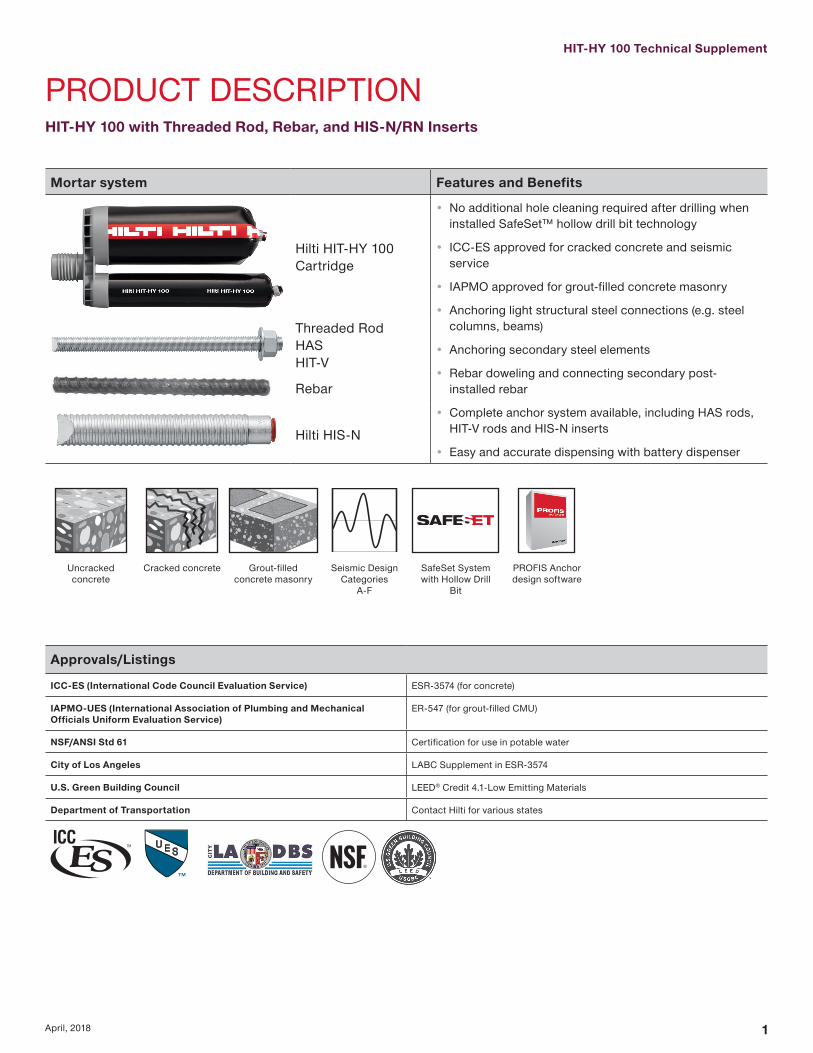
HIT-HY 100 Technical Supplement
1April 2018
PRODUCT DESCRIPTIONHIT-HY 100 with Threaded Rod Rebar and HIS-NRN Inserts
Mortar system Features and Benefits
Hilti HIT-HY 100 Cartridge
bull No additional hole cleaning required after drilling when installed SafeSettrade hollow drill bit technology
bull ICC-ES approved for cracked concrete and seismic service
bull IAPMO approved for grout-filled concrete masonry
bull Anchoring light structural steel connections (eg steel columns beams)
bull Anchoring secondary steel elements
bull Rebar doweling and connecting secondary post-installed rebar
bull Complete anchor system available including HAS rods HIT-V rods and HIS-N inserts
bull Easy and accurate dispensing with battery dispenser
Threaded RodHASHIT-V
Rebar
Hilti HIS-N
Uncracked concrete
Cracked concrete Grout-filled concrete masonry
Seismic Design Categories
A-F
SafeSet Systemwith Hollow Drill
Bit
PROFIS Anchor design software
ApprovalsListings
ICC-ES (International Code Council Evaluation Service) ESR-3574 (for concrete)
IAPMO-UES (International Association of Plumbing and Mechanical Officials Uniform Evaluation Service)
ER-547 (for grout-filled CMU)
NSFANSI Std 61 Certification for use in potable water
City of Los Angeles LABC Supplement in ESR-3574
US Green Building Council LEEDreg Credit 41-Low Emitting Materials
Department of Transportation Contact Hilti for various states
2 April 2018
DESIGN DATA IN CONCRETE PER ACI 318 ACI 318-14 Chapter 17 design The technical data contained in this section are Hilti Simplified Design Tables The load values were developed using the Strength Design parameters developed through testing per ACI 3554 and the equations within ACI 318-14 Chapter 17 For a detailed explanation of the Hilti Simplified Design Tables refer to of the Hilti North American Product Technical Guide Volume 2 Anchor Fastening Technical Guide Edition 17
For additional information or technical assistance contact Hilti at 800-879-5000 (US) or 800-363-4459 (CA)
Hilti HIT-HY 100 Adhesive with Deformed Reinforcing Bars (Rebar)
Rebar installation conditions
Perm
issi
ble
Bas
e M
ater
ials
Uncracked concrete
DryConcrete
Perm
issi
ble
Dril
ling
Met
hod
Hammer Drilling with Carbide Tipped
Drill Bit
Cracked concrete
Water Saturated Concrete
Hollow Drill Bit
US rebar installation specifications
RebarSize
DrillBit
Dia
StandardEmbedDepth
EmbedDepthRange
MinimumBase Material
Thickness
d0in
hef stdin (mm)
hefin (mm)
hminin (mm)
3 123-38 2-38 ndash 7-12
hef + 1-14(hef + 30)
(86) (60 ndash 191)
4 584-12 2-34 ndash 10
(114) (70 ndash 254)
5 345-58 3-18 ndash 12-12
hef + 2d0
(143) (79 ndash 318)
6 786-34 3-12 ndash 15
(171) (89 ndash 381)
7 17-78 3-12 ndash 17-12
(200) (89 ndash 445)
8 1-189 4 ndash 20
(229) (102 ndash 508)
9 1-3810-18 4-12 ndash 22-12
(257) (114 ndash 572)
10 1-1211-14 5 ndash 25
(286) (127 ndash 635)
Canadian rebar installation specifications
RebarSize
DrillBit
Dia
StandardEmbedDepth
EmbedDepthRange
MinimumBase Material
Thickness
d0in
hef stdmm
hefmm
hminmm
10 M 916 115 70 ndash 226 hef + 30
15 M 34 145 80 ndash 320
hef + 2d0
20 M 1 200 90 ndash 390
25 M 1-14 230 101 ndash 504
30 M 1-12 260 120 ndash 598
HIT-HY 100 Technical Supplement
3April 2018
Table 1 mdash Hilti HIT-HY 100 adhesive design strength with concrete bond failure for US rebar in uncracked concrete 12345678
Rebar sizeEffective
embedmentin (mm)
Tension mdash ϕNn Shear mdash ϕVn
f c = 2500 psi(172 Mpa)
lb (kN)
f c = 3000 psi(207 Mpa)
lb (kN)
f c = 4000 psi(276 Mpa)
lb (kN)
f c = 6000 psi(414 Mpa)
lb (kN)
f c = 2500 psi(172 Mpa)
lb (kN)
f c = 3000 psi(207 Mpa)
lb (kN)
f c = 4000 psi(276 Mpa)
lb (kN)
f c = 6000 psi(414 Mpa)
lb (kN)
3
3-38 3295 3355 3455 3595 7095 7230 7440 7745(86) (147) (149) (154) (160) (316) (322) (331) (345)
4-12 4395 4475 4605 4795 9465 9635 9920 10330(114) (195) (199) (205) (213) (421) (429) (441) (459)7-12 7325 7455 7675 7995 15770 16060 16530 17215(191) (326) (332) (341) (356) (701) (714) (735) (766)
4
4-12 5810 5920 6090 6345 12520 12750 13120 13665(114) (258) (263) (271) (282) (557) (567) (584) (608)
6 7750 7890 8120 8460 16690 17000 17495 18220(152) (345) (351) (361) (376) (742) (756) (778) (810)10 12915 13155 13535 14100 27820 28330 29160 30365
(254) (574) (585) (602) (627) (1237) (1260) (1297) (1351)
5
5-58 8995 9160 9430 9820 19375 19730 20305 21145(143) (400) (407) (419) (437) (862) (878) (903) (941)7-12 11995 12215 12570 13090 25835 26310 27075 28195(191) (534) (543) (559) (582) (1149) (1170) (1204) (1254)
12-12 19990 20355 20950 21820 43055 43845 45125 46995(318) (889) (905) (932) (971) (1915) (1950) (2007) (2090)
6
6-34 12820 13055 13435 13990 27610 28120 28940 30135(171) (570) (581) (598) (622) (1228) (1251) (1287) (1340)
9 17090 17405 17915 18655 36815 37490 38585 40180(229) (760) (774) (797) (830) (1638) (1668) (1716) (1787)
15 28485 29010 29855 31095 61355 62485 64310 66970(381) (1267) (1290) (1328) (1383) (2729) (2779) (2861) (2979)
7
7-78 17235 17625 18140 18890 37125 37965 39070 40690(200) (767) (784) (807) (840) (1651) (1689) (1738) (1810)
10-12 23075 23500 24185 25190 49705 50615 52095 54250(267) (1026) (1045) (1076) (1121) (2211) (2251) (2317) (2413)17-12 38460 39170 40310 41980 82840 84360 86825 90415(445) (1711) (1742) (1793) (1867) (3685) (3753) (3862) (4022)
8
9 21060 22835 23500 24475 45360 49180 50615 52710(229) (937) (1016) (1045) (1089) (2018) (2188) (2251) (2345)
12 29895 30445 31335 32630 64390 65575 67490 70280(305) (1330) (1354) (1394) (1451) (2864) (2917) (3002) (3126)
20 49825 50740 52225 54385 107315 109290 112480 117135(508) (2216) (2257) (2323) (2419) (4774) (4861) (5003) (5210)
9
10-18 22635 23050 23725 24705 54125 58675 60385 62885(257) (1007) (1025) (1055) (1099) (2408) (2610) (2686) (2797)
13-12 30180 30735 31630 32940 76820 78230 80515 83845(343) (1342) (1367) (1407) (1465) (3417) (3480) (3581) (3730)
22-12 50295 51225 52720 54900 128030 130385 134190 139745(572) (2237) (2279) (2345) (2442) (5695) (5800) (5969) (6216)
10
11-14 25025 25490 26230 27315 63395 64880 66770 69535(286) (1113) (1134) (1167) (1215) (2820) (2886) (2970) (3093)
15 33370 33985 34975 36425 84940 86505 89030 92710(381) (1484) (1512) (1556) (1620) (3778) (3848) (3960) (4124)25 55615 56640 58290 60705 141570 144175 148380 154520
(635) (2474) (2519) (2593) (2700) (6297) (6413) (6600) (6873)1 See Section 318 (2017 PTG) for explanation on development of load values2 See Section 3186 (2017 PTG) to convert design strength value to ASD value3 Linear interpolation between embedment depths and concrete compressive strengths is not permitted4 Load values are for a single anchor with no spacing edge distance or concrete thickness factors Apply spacing edge distance and concrete thickness factors in tables 4-19 as
necessary Compare to the steel values in table 3 The lesser of the values is to be used for the design5 Data is for temperature range A Max short term temperature = 130degF (55degC) max long term temperature = 110degF (43degC)
For temperature range B Max short term temperature = 176degF (80degC) max long term temperature = 110degF (43degC) multiply above value by 092 For temperature range C Max short term temperature = 210degF (99degC) max long term temperature = 162degF (72degC) multiply above value by 071 Short term elevated concrete temperatures are those that occur over brief intervals eg as a result of diurnal cycling Long term concrete temperatures are roughly constant over significant periods of time
6 Tabular values are for dry concrete conditions For water saturated concrete multiply design strength (factored resistance) by 0857 Tabular values are for short term loads only For sustained loads including overhead use see Section 3188 (2017 PTG)8 Tabular values are for normal-weight concrete only For lightweight concrete multiply design strength by λa as follows
For sand-lightweight λa = 051 For all-lightweight λa = 045
4 April 2018
Table 2 mdash Hilti HIT-HY 100 adhesive design strength with concrete bond failure for US rebar in cracked concrete 12345678
Rebar sizeEffective
embedmentin (mm)
Tension mdash ϕNn Shear mdash ϕVn
f´c = 2500 psi(172 Mpa)
lb (kN)
f´c = 3000 psi(207 Mpa)
lb (kN)
f´c = 4000 psi(276 Mpa)
lb (kN)
f´c = 6000 psi(414 Mpa)
lb (kN)
f´c = 2500 psi(172 Mpa)
lb (kN)
f´c = 3000 psi(207 Mpa)
lb (kN)
f´c = 4000 psi(276 Mpa)
lb (kN)
f´c = 6000 psi(414 Mpa)
lb (kN)
3
3-38 1575 1605 1650 1720 3395 3460 3560 3705(86) (70) (71) (73) (77) (151) (154) (158) (165)
4-12 2100 2140 2205 2295 4525 4610 4745 4940(114) (93) (95) (98) (102) (201) (205) (211) (220)7-12 3505 3570 3670 3825 7545 7685 7910 8235(191) (156) (159) (163) (170) (336) (342) (352) (366)
4
4-12 3080 3135 3225 3360 6630 6750 6950 7235(114) (137) (139) (143) (149) (295) (300) (309) (322)
6 4105 4180 4300 4480 8840 9005 9265 9650(152) (183) (186) (191) (199) (393) (401) (412) (429)10 6840 6965 7170 7465 14735 15005 15445 16080
(254) (304) (310) (319) (332) (655) (667) (687) (715)
5
5-58 5205 5300 5455 5680 11210 11415 11750 12235(143) (232) (236) (243) (253) (499) (508) (523) (544)7-12 6940 7065 7275 7575 14945 15220 15665 16315(191) (309) (314) (324) (337) (665) (677) (697) (726)
12-12 11565 11780 12125 12625 24910 25370 26110 27190(318) (514) (524) (539) (562) (1108) (1129) (1161) (1209)
6
6-34 8010 8160 8395 8745 17255 17575 18085 18835(171) (356) (363) (373) (389) (768) (782) (804) (838)
9 10680 10880 11195 11660 23010 23430 24115 25115(229) (475) (484) (498) (519) (1024) (1042) (1073) (1117)
15 17805 18130 18660 19435 38345 39055 40190 41855(381) (792) (806) (830) (865) (1706) (1737) (1788) (1862)
7
7-78 10975 11175 11505 11980 23640 24075 24775 25800(200) (488) (497) (512) (533) (1052) (1071) (1102) (1148)
10-12 14635 14905 15340 15975 31520 32100 33035 34405(267) (651) (663) (682) (711) (1402) (1428) (1469) (1530)17-12 24390 24840 25565 26620 52530 53500 55060 57340(445) (1085) (1105) (1137) (1184) (2337) (2380) (2449) (2551)
8
9 14520 14785 15220 15845 31270 31845 32775 34135(229) (646) (658) (677) (705) (1391) (1417) (1458) (1518)
12 19360 19715 20290 21130 41695 42460 43700 45510(305) (861) (877) (903) (940) (1855) (1889) (1944) (2024)
20 32265 32860 33815 35215 69490 70770 72835 75850(508) (1435) (1462) (1504) (1566) (3091) (3148) (3240) (3374)
9
10-18 15645 15935 16400 17080 38340 40560 41745 43470(257) (696) (709) (730) (760) (1705) (1804) (1857) (1934)
13-12 20860 21245 21865 22770 53105 54080 55660 57965(343) (928) (945) (973) (1013) (2362) (2406) (2476) (2578)
22-12 34770 35410 36445 37950 88510 90135 92765 96605(572) (1547) (1575) (1621) (1688) (3937) (4009) (4126) (4297)
10
11-14 19560 19920 20500 21350 44905 49190 52185 54345(286) (870) (886) (912) (950) (1997) (2188) (2321) (2417)
15 26080 26560 27335 28465 66385 67605 69580 72460(381) (1160) (1181) (1216) (1266) (2953) (3007) (3095) (3223)25 43465 44265 45560 47445 110645 112680 115965 120765
(635) (1921) (1957) (2014) (2097) (4891) (4981) (5126) (5339)1 See Section 318 (2017 PTG) for explanation on development of load values2 See Section 3186 (2017 PTG) to convert design strength value to ASD value3 Linear interpolation between embedment depths and concrete compressive strengths is not permitted4 Load values are for a single anchor with no spacing edge distance or concrete thickness factors Apply spacing edge distance and concrete thickness factors in tables 4-19 as
necessary Compare to the steel values in table 3 The lesser of the values is to be used for the design5 Data is for temperature range A Max short term temperature = 104degF (40degC) max long term temperature = 75degF (24degC)
For temperature range B Max short term temperature = 176degF (80degC) max long term temperature = 110degF (43degC) multiply above value by 092 For temperature range C Max short term temperature = 210degF (99degC) max long term temperature = 162degF (72degC) multiply above value by 071 Short term elevated concrete temperatures are those that occur over brief intervals eg as a result of diurnal cycling Long term concrete temperatures are roughly constant over significant periods of time
6 Tabular values are for dry concrete conditions For water saturated concrete multiply design strength (factored resistance) by 0857 Tabular values are for short term loads only For sustained loads including overhead use see Section 3188 (2017 PTG)8 Tabular values are for normal-weight concrete only For lightweight concrete multiply design strength by λa as follows
For sand-lightweight λa = 051 For all-lightweight λa = 0459 Tabular values are for static loads only For seismic loads multiply cracked concrete tabular values in tension and shear by αseis = 075 See section 3187 (2017 PTG) for additional information on seismic applications
HIT-HY 100 Technical Supplement
5April 2018
Table 3 mdash Steel design strength for US rebar 12
Rebar size
ASTM A 615 Grade 40 ASTM A 615 Grade 60 ASTM A 706 Grade 60
Tensile3
ϕNsalb (kN)
Shear4
ϕVsalb (kN)
Seismic Shear5
ϕVsaeqlb (kN)
Tensile3
ϕNsalb (kN)
Shear4
ϕVsalb (kN)
Seismic Shear5
ϕVsaeqlb (kN)
Tensile3
ϕNsalb (kN)
Shear4
ϕVsalb (kN)
Seismic Shear5
ϕVsaeqlb (kN)
34290 2375 1665 6435 3565 2495 6600 3430 2400(191) (106) (74) (286) (159) (111) (294) (153) (107)
47800 4320 3025 11700 6480 4535 12000 6240 4370(347) (192) (135) (520) (288) (202) (534) (278) (194)
512090 6695 4685 18135 10045 7030 18600 9670 6770(538) (298) (208) (807) (447) (313) (827) (430) (301)
617160 9505 6655 25740 14255 9980 26400 13730 9610(763) (423) (296) (1145) (634) (444) (1174) (611) (427)
723400 12960 9070 35100 19440 13610 36000 18720 13105(1041) (576) (403) (1561) (865) (605) (1601) (833) (583)
830810 17065 11945 46215 25595 17915 47400 24650 17255(1370) (759) (531) (2056) (1139) (797) (2108) (1096) (768)
939000 21600 15120 58500 32400 22680 60000 31200 21840(1735) (961) (673) (2602) (1441) (1009) (2669) (1388) (971)
1049530 27430 19200 74295 41150 28805 76200 39625 27740(2203) (1220) (854) (3305) (1830) (1281) (3390) (1763) (1234)
1 See Section 3186 (2017 PTG) to convert design strength value to ASD value2 ASTM A706 Grade 60 rebar are considered ductile steel elements ASTM A 615 Grade 40 and 60 rebar are considered brittle steel elements3 Tensile = ϕ AseN futa as noted in ACI 318 Chapter 174 Shear = ϕ 060 AseN futa as noted in ACI 318 Chapter 175 Seismic Shear = αVseis ϕVsa Reduction for seismic shear only See section 3187 (2017 PTG) for additional information on seismic applications
6 April 2018
Table 4 mdash Load adjustment factors for 3 rebar in uncracked concrete 123
3Uncracked concrete
Spacing factor in tension
fAN
Edge distance factor in tension
fRN
Spacing factor in shear 4
fAV
Edge distance in shearConcrete thickness
factor in shear 5
fHV
Toward edge
fRV
To edge
fRV
Embedment hefin (mm)
3-38 4-12 7-12 3-38 4-12 7-12 3-38 4-12 7-12 3-38 4-12 7-12 3-38 4-12 7-12 3-38 4-12 7-12(86) (114) (191) (86) (114) (191) (86) (114) (191) (86) (114) (191) (86) (114) (191) (86) (114) (191)
Spac
ing
(s)
edg
e di
stan
ce (c
a) c
oncr
ete
thic
knes
s (h
) - i
n (m
m)
1-34 (44) na na na 032 023 013 na na na 010 008 005 021 016 009 na na na1-78 (48) 059 057 054 033 024 014 054 053 052 012 009 005 023 017 010 na na na
2 (51) 060 057 054 034 025 014 054 053 052 013 010 006 025 019 011 na na na3 (76) 065 061 057 042 031 018 056 055 054 023 017 010 042 031 018 na na na4 (102) 070 065 059 052 038 022 058 057 055 036 027 016 052 038 022 na na na
4-58 (117) 073 067 060 060 043 025 060 058 056 045 033 020 060 043 025 062 na na5 (127) 075 069 061 064 047 027 061 059 056 050 038 023 064 047 027 065 na na
5-34 (146) 078 071 063 074 054 031 062 060 057 062 046 028 074 054 031 070 063 na6 (152) 080 072 063 077 056 033 063 060 057 066 049 030 077 056 033 071 065 na7 (178) 085 076 066 090 066 038 065 062 059 083 062 037 090 066 038 077 070 na8 (203) 090 080 068 100 075 043 067 064 060 100 076 046 100 075 043 082 075 na
8-34 (222) 093 082 069 082 048 068 065 061 087 052 082 048 086 078 0669 (229) 094 083 070 084 049 069 066 061 091 055 084 049 087 079 06710 (254) 099 087 072 094 054 071 067 062 100 064 094 054 092 083 07011 (279) 100 091 074 100 060 073 069 064 074 100 060 096 087 07412 (305) 094 077 065 075 071 065 084 065 100 091 07714 (356) 100 081 076 079 074 067 100 076 099 08316 (406) 086 087 084 078 070 087 100 08918 (457) 090 098 088 081 072 098 09424 (610) 100 100 100 092 080 100 10030 (762) 100 08736 (914) 094
gt 48 (1219) 100
Table 5 mdash Load adjustment factors for 3 rebar in cracked concrete 123
3Cracked concrete
Spacing factor in tension
fAN
Edge distance factor in tension
fRN
Spacing factor in shear 4
fAV
Edge distance in shearConcrete thickness
factor in shear 5
fHV
Toward edge
fRV
To edge
fRV
Embedment hefin (mm)
3-38 4-12 7-12 3-38 4-12 7-12 3-38 4-12 7-12 3-38 4-12 7-12 3-38 4-12 7-12 3-38 4-12 7-12(86) (114) (191) (86) (114) (191) (86) (114) (191) (86) (114) (191) (86) (114) (191) (86) (114) (191)
Spac
ing
(s)
edg
e di
stan
ce (c
a) c
oncr
ete
thic
knes
s (h
) - i
n (m
m)
1-34 (44) na na na 054 049 043 na na na 010 007 004 020 015 009 na na na1-78 (48) 059 057 054 056 050 044 054 053 052 011 008 005 022 017 010 na na na
2 (51) 060 057 054 057 051 044 054 053 052 012 009 005 024 018 011 na na na3 (76) 065 061 057 070 060 049 056 055 054 022 017 010 045 034 020 na na na4 (102) 070 065 059 084 070 055 058 057 055 034 026 015 069 052 031 na na na
4-58 (117) 073 067 060 093 076 058 059 058 056 043 032 019 086 064 038 062 na na5 (127) 075 069 061 099 080 060 060 058 056 048 036 022 096 072 043 064 na na
5-34 (146) 078 071 063 100 088 064 062 060 057 059 044 027 100 088 053 069 062 na6 (152) 080 072 063 091 066 062 060 057 063 047 028 091 057 070 064 na7 (178) 085 076 066 100 072 064 062 058 080 060 036 100 072 076 069 na8 (203) 090 080 068 078 066 064 060 097 073 044 078 081 074 na
8-34 (222) 093 082 069 083 068 065 061 100 083 050 083 085 077 0659 (229) 094 083 070 085 068 065 061 087 052 085 086 078 06610 (254) 099 087 072 091 070 067 062 100 061 091 090 082 06911 (279) 100 091 074 098 073 069 063 071 098 095 086 07312 (305) 094 077 100 075 070 064 080 100 099 090 07614 (356) 100 081 100 079 074 067 100 100 097 08216 (406) 086 083 077 069 100 08818 (457) 090 087 080 072 09324 (610) 100 099 091 079 10030 (762) 100 100 08636 (914) 093
gt 48 (1219) 1001 Linear interpolation not permitted2 Shaded area with reduced edge distance is permitted provided the rebar has no installation torque3 When combining multiple load adjustment factors (eg for a four-anchor pattern in a corner with thin concrete member) the design can become very conservative To optimize the design
use Hilti PROFIS Anchor Design software or perform anchor calculation using design equations from ACI 318 Chapter 174 Spacing factor reduction in shear applicable when ca lt 3hef ƒAV is applicable when edge distance ca lt 3hef If ca ge 3hef then ƒAV = ƒAN 5 Concrete thickness reduction factor in shear ƒHV is applicable when edge distance ca lt 3hef If ca ge 3hef then ƒHV = 10
HIT-HY 100 Technical Supplement
7April 2018
Table 6 mdash Load adjustment factors for 4 rebar in uncracked concrete 123
4Uncracked concrete
Spacing factor in tension
fAN
Edge distance factor in tension
fRN
Spacing factor in shear 4
fAV
Edge distance in shearConcrete thickness
factor in shear 5
fHV
Toward edge
fRV
To edge
fRV
Embedment hefin (mm)
4-12 6 10 4-12 6 10 4-12 6 10 4-12 6 10 4-12 6 10 4-12 6 10 (114) (152) (254) (114) (152) (254) (114) (152) (254) (114) (152) (254) (114) (152) (254) (114) (152) (254)
Spac
ing
(s)
edg
e di
stan
ce (c
a) c
oncr
ete
thic
knes
s (h
) - i
n (m
m)
1-34 (44) na na na 027 020 012 na na na 007 005 003 014 010 006 na na na2-12 (64) 059 057 054 032 023 014 054 053 052 012 009 005 023 017 010 na na na
3 (76) 061 058 055 035 026 015 055 054 053 015 011 007 031 023 014 na na na4 (102) 065 061 057 041 030 018 056 055 054 023 018 011 041 030 018 na na na5 (127) 069 064 058 048 035 021 058 057 055 033 025 015 048 035 021 na na na
5-34 (146) 071 066 060 054 040 023 059 058 055 040 030 018 054 040 023 060 na na6 (152) 072 067 060 056 041 024 060 058 056 043 032 019 056 041 024 062 na na7 (178) 076 069 062 066 048 028 061 059 057 054 041 024 066 048 028 067 na na
7-14 (184) 077 070 062 068 050 029 062 059 057 057 043 026 068 050 029 068 062 na8 (203) 080 072 063 075 055 032 063 060 057 066 050 030 075 055 032 071 065 na9 (229) 083 075 065 085 062 036 064 062 058 079 059 036 085 062 036 076 069 na10 (254) 087 078 067 094 069 040 066 063 059 093 070 042 094 069 040 080 072 na
11-14 (286) 092 081 069 100 078 045 068 065 060 100 083 050 100 078 045 084 077 06512 (305) 094 083 070 083 048 069 066 061 092 055 083 048 087 079 06714 (356) 100 089 073 097 056 072 068 063 100 069 097 056 094 086 07216 (406) 094 077 100 065 075 071 065 085 100 065 100 092 07718 (457) 100 080 073 079 074 067 100 073 097 08220 (508) 083 081 082 076 069 081 100 08622 (559) 087 089 085 079 070 089 09124 (610) 090 097 088 081 072 097 09530 (762) 100 100 098 089 078 100 10036 (914) 100 097 084
gt 48 (1219) 100 095
Table 7 mdash Load adjustment factors for 4 rebar in cracked concrete 123
4Cracked concrete
Spacing factor in tension
fAN
Edge distance factor in tension
fRN
Spacing factor in shear 4
fAV
Edge distance in shearConcrete thickness
factor in shear 5
fHV
Toward edge
fRV
To edge
fRV
Embedment hefin (mm)
4-12 6 10 4-12 6 10 4-12 6 10 4-12 6 10 4-12 6 10 4-12 6 10 (114) (152) (254) (114) (152) (254) (114) (152) (254) (114) (152) (254) (114) (152) (254) (114) (152) (254)
Spac
ing
(s)
edg
e di
stan
ce (c
a) c
oncr
ete
thic
knes
s (h
) - i
n (m
m)
1-34 (44) na na na 049 045 041 na na na 006 005 003 013 010 006 na na na2-12 (64) 059 057 054 056 050 044 054 053 052 011 008 005 022 017 010 na na na
3 (76) 061 058 055 060 053 046 055 054 053 015 011 007 029 022 013 na na na4 (102) 065 061 057 070 060 049 056 055 054 022 017 010 045 034 020 na na na5 (127) 069 064 058 080 067 053 058 056 055 031 023 014 062 047 028 na na na
5-34 (146) 071 066 060 088 073 056 059 057 055 039 029 017 077 058 035 059 na na6 (152) 072 067 060 091 075 057 059 058 055 041 031 018 082 062 037 061 na na7 (178) 076 069 062 100 083 062 061 059 056 052 039 023 100 078 047 066 na na
7-14 (184) 077 070 062 085 063 061 059 057 055 041 025 082 049 067 061 na8 (203) 080 072 063 091 066 062 060 057 063 047 028 091 057 070 064 na9 (229) 083 075 065 100 070 064 061 058 075 057 034 100 068 074 068 na10 (254) 087 078 067 075 065 063 059 088 066 040 075 078 071 na
11-14 (286) 092 081 069 081 067 064 060 100 079 047 081 083 075 06412 (305) 094 083 070 085 068 065 061 087 052 085 086 078 06614 (356) 100 089 073 095 071 068 063 100 066 095 093 084 07116 (406) 094 077 100 075 070 064 080 100 099 090 07618 (457) 100 080 078 073 066 096 100 095 08120 (508) 083 081 075 068 100 100 08522 (559) 087 084 078 070 08924 (610) 090 087 080 072 09330 (762) 100 096 088 077 10036 (914) 100 096 082
gt 48 (1219) 100 0931 Linear interpolation not permitted2 Shaded area with reduced edge distance is permitted provided the rebar has no installation torque3 When combining multiple load adjustment factors (eg for a four-anchor pattern in a corner with thin concrete member) the design can become very conservative To optimize the design
use Hilti PROFIS Anchor Design software or perform anchor calculation using design equations from ACI 318 Chapter 174 Spacing factor reduction in shear applicable when ca lt 3hef ƒAV is applicable when edge distance ca lt 3hef If ca ge 3hef then ƒAV = ƒAN 5 Concrete thickness reduction factor in shear ƒHV is applicable when edge distance ca lt 3hef If ca ge 3hef then ƒHV = 10
8 April 2018
Table 8 mdash Load adjustment factors for 5 rebar in uncracked concrete 123
5Uncracked concrete
Spacing factor in tension
fAN
Edge distance factor in tension
fRN
Spacing factor in shear 4
fAV
Edge distance in shearConcrete thickness
factor in shear 5
fHV
Toward edge
fRV
To edge
fRV
Embedment hefin (mm)
5-58 7-12 12-12 5-58 7-12 12-12 5-58 7-12 12-12 5-58 7-12 12-12 5-58 7-12 12-12 5-58 7-12 12-12(143) (191) (318) (143) (191) (318) (143) (191) (318) (143) (191) (318) (143) (191) (318) (143) (191) (318)
Spac
ing
(s)
edg
e di
stan
ce (c
a) c
oncr
ete
thic
knes
s (h
) - i
n (m
m)
1-34 (44) na na na 025 019 011 na na na 005 004 002 010 007 004 na na na2-12 (64) 059 057 054 032 023 014 054 053 052 012 009 005 023 018 011 na na na
3 (76) 062 059 055 036 026 015 055 054 053 017 013 008 034 025 015 na na na4 (102) 065 061 057 041 030 018 056 055 054 024 018 011 041 030 018 na na na5 (127) 068 063 058 047 034 020 058 056 055 031 023 014 047 034 020 na na na
5-34 (146) 071 066 059 053 039 023 059 057 055 039 029 018 053 039 023 na na na6 (152) 071 066 060 054 039 023 059 058 055 040 030 018 054 039 023 060 na na7 (178) 074 068 061 060 044 026 060 058 056 048 036 022 060 044 026 064 na na
7-14 (184) 077 070 062 068 050 029 061 059 057 057 043 026 068 050 029 068 062 na8 (203) 080 072 063 075 055 032 063 061 058 067 050 030 075 055 032 071 065 na9 (229) 083 074 065 083 061 036 064 062 058 077 058 035 083 061 036 075 068 na10 (254) 086 077 066 090 066 039 065 063 059 088 066 040 090 066 039 078 071 na
11-14 (286) 091 081 069 100 077 045 068 065 061 100 083 050 100 077 045 085 077 06512 (305) 097 086 071 088 052 070 067 062 100 061 088 052 090 082 06914 (356) 100 090 074 099 058 073 069 064 073 099 058 096 087 07316 (406) 094 077 100 065 076 071 065 085 100 065 100 092 07718 (457) 099 079 071 078 073 067 099 071 096 08120 (508) 100 082 078 081 075 068 100 078 100 08522 (559) 085 084 083 077 070 084 08824 (610) 087 091 086 080 071 091 09230 (762) 090 097 088 082 073 097 09536 (914) 098 100 096 088 077 100 100
gt 48 (1219) 100 100 100 086
Table 9 mdash Load adjustment factors for 5 rebar in cracked concrete 123
5Cracked concrete
Spacing factor in tension
fAN
Edge distance factor in tension
fRN
Spacing factor in shear 4
fAV
Edge distance in shearConcrete thickness
factor in shear 5
fHV
Toward edge
fRV
To edge
fRV
Embedment hefin (mm)
5-58 7-12 12-12 5-58 7-12 12-12 5-58 7-12 12-12 5-58 7-12 12-12 5-58 7-12 12-12 5-58 7-12 12-12(143) (191) (318) (143) (191) (318) (143) (191) (318) (143) (191) (318) (143) (191) (318) (143) (191) (318)
Spac
ing
(s)
edg
e di
stan
ce (c
a) c
oncr
ete
thic
knes
s (h
) - i
n (m
m)
1-34 (44) na na na 046 043 040 na na na 005 003 002 009 007 004 na na na2-12 (64) 059 057 054 056 050 044 054 053 052 011 008 005 022 017 010 na na na
3 (76) 062 059 055 062 055 046 055 054 053 016 012 007 032 024 014 na na na4 (102) 065 061 057 070 060 049 056 055 054 022 017 010 045 034 020 na na na5 (127) 068 063 058 078 066 053 057 056 054 029 022 013 059 044 026 na na na
5-34 (146) 071 066 059 087 072 056 059 057 055 037 028 017 074 056 033 na na na6 (152) 071 066 060 088 073 056 059 057 055 038 029 017 076 057 034 059 na na7 (178) 074 068 061 096 078 059 060 058 056 045 034 020 090 068 041 063 na na
7-14 (184) 077 070 062 100 085 062 061 059 056 054 040 024 100 081 049 066 060 na8 (203) 080 072 063 091 066 062 060 057 063 047 028 091 057 070 064 na9 (229) 083 074 065 098 069 064 061 058 073 055 033 098 066 073 067 na10 (254) 086 077 066 100 073 065 062 059 083 062 037 100 073 077 070 na
11-14 (286) 091 081 069 081 067 064 060 100 079 047 081 083 075 06412 (305) 097 086 071 089 070 066 062 096 058 089 089 081 06814 (356) 100 090 074 097 072 068 063 100 069 097 094 085 07216 (406) 094 077 100 075 070 064 080 100 099 090 07618 (457) 099 079 077 072 066 093 100 094 08020 (508) 100 082 079 074 067 100 099 08322 (559) 085 082 076 069 100 08724 (610) 087 084 078 070 09030 (762) 090 087 080 072 09336 (914) 098 094 086 076 100
gt 48 (1219) 100 100 099 0851 Linear interpolation not permitted2 Shaded area with reduced edge distance is permitted provided the rebar has no installation torque3 When combining multiple load adjustment factors (eg for a four-anchor pattern in a corner with thin concrete member) the design can become very conservative To optimize the design
use Hilti PROFIS Anchor Design software or perform anchor calculation using design equations from ACI 318 Chapter 174 Spacing factor reduction in shear applicable when ca lt 3hef ƒAV is applicable when edge distance ca lt 3hef If ca ge 3hef then ƒAV = ƒAN 5 Concrete thickness reduction factor in shear ƒHV is applicable when edge distance ca lt 3hef If ca ge 3hef then ƒHV = 10
HIT-HY 100 Technical Supplement
9April 2018
Table 10 mdash Load adjustment factors for 6 rebar in uncracked concrete 123
6Uncracked concrete
Spacing factor in tension
fAN
Edge distance factor in tension
fRN
Spacing factor in shear 4
fAV
Edge distance in shearConcrete thickness
factor in shear 5
fHV
Toward edge
fRV
To edge
fRV
Embedment hefin (mm)
6-34 9 15 6-34 9 15 6-34 9 15 6-34 9 15 6-34 9 15 6-34 9 15 (171) (229) (381) (171) (229) (381) (171) (229) (381) (171) (229) (381) (171) (229) (381) (171) (229) (381)
Spac
ing
(s)
edg
e di
stan
ce (c
a) c
oncr
ete
thic
knes
s (h
) - i
n (m
m)
1-34 (44) na na na 024 018 010 na na na 004 003 002 007 006 003 na na na3-34 (95) 059 057 054 032 023 014 054 053 052 012 009 005 023 017 010 na na na
4 (102) 060 057 054 033 024 014 054 053 052 013 010 006 026 019 012 na na na5 (127) 062 059 056 037 027 016 055 054 053 018 013 008 036 027 016 na na na6 (152) 065 061 057 041 030 018 056 055 054 023 018 011 041 030 018 na na na8 (203) 070 065 059 051 037 022 058 057 055 036 027 016 051 037 022 na na na
8-12 (216) 071 066 059 053 039 023 059 057 055 040 030 018 053 039 023 060 na na10 (254) 075 069 061 063 046 027 061 059 056 051 038 023 063 046 027 065 na na
10-34 (273) 077 070 062 068 050 029 061 059 057 056 042 025 068 050 029 067 061 na12 (305) 080 072 063 075 055 032 063 060 057 066 050 030 075 055 032 071 065 na14 (356) 085 076 066 088 065 038 065 062 059 084 063 038 088 065 038 077 070 na16 (406) 090 080 068 100 074 043 067 064 060 100 077 046 100 074 043 082 075 na
16-34 (425) 091 081 069 077 045 068 065 060 082 049 077 045 084 076 06418 (457) 094 083 070 083 049 069 066 061 091 055 083 049 087 079 06720 (508) 099 087 072 092 054 071 067 062 100 064 092 054 092 084 07022 (559) 100 091 074 100 059 073 069 064 074 100 059 096 088 07424 (610) 094 077 065 075 071 065 085 065 100 092 07726 (660) 098 079 070 077 073 066 095 070 095 08028 (711) 100 081 076 080 074 067 100 076 099 08330 (762) 083 081 082 076 069 081 100 08636 (914) 090 097 088 081 072 097 095
gt 48 (1219) 100 100 100 092 080 100 100
Table 11 mdash Load adjustment factors for 6 rebar in cracked concrete 123
6Cracked concrete
Spacing factor in tension
fAN
Edge distance factor in tension
fRN
Spacing factor in shear 4
fAV
Edge distance in shearConcrete thickness
factor in shear 5
fHV
Toward edge
fRV
To edge
fRV
Embedment hefin (mm)
6-34 9 15 6-34 9 15 6-34 9 15 6-34 9 15 6-34 9 15 6-34 9 15 (171) (229) (381) (171) (229) (381) (171) (229) (381) (171) (229) (381) (171) (229) (381) (171) (229) (381)
Spac
ing
(s)
edg
e di
stan
ce (c
a) c
oncr
ete
thic
knes
s (h
) - i
n (m
m)
1-34 (44) na na na 044 042 039 na na na 003 003 002 007 005 003 na na na3-34 (95) 059 057 054 056 050 044 054 053 052 011 008 005 022 016 010 na na na
4 (102) 060 057 054 057 051 044 054 053 052 012 009 005 024 018 011 na na na5 (127) 062 059 056 063 056 047 055 054 053 017 012 007 034 025 015 na na na6 (152) 065 061 057 070 060 049 056 055 054 022 016 010 044 033 020 na na na8 (203) 070 065 059 084 070 055 058 057 055 034 025 015 068 051 030 na na na
8-12 (216) 071 066 059 088 072 056 059 057 055 037 028 017 075 055 033 059 na na10 (254) 075 069 061 099 080 060 060 058 056 048 035 021 095 071 042 064 na na
10-34 (273) 077 070 062 100 084 062 061 059 056 053 039 024 100 079 047 066 060 na12 (305) 080 072 063 091 066 062 060 057 063 046 028 091 056 070 063 na14 (356) 085 076 066 100 072 064 062 058 079 059 035 100 070 076 068 na16 (406) 090 080 068 078 066 063 059 097 071 043 078 081 073 na
16-34 (425) 091 081 069 081 067 064 060 100 077 046 081 083 075 06318 (457) 094 083 070 085 068 065 061 085 051 085 086 077 06520 (508) 099 087 072 091 070 067 062 100 060 091 090 082 06922 (559) 100 091 074 098 072 068 063 069 098 095 086 07224 (610) 094 077 100 074 070 064 079 100 099 089 07526 (660) 098 079 076 072 065 089 100 093 07828 (711) 100 081 079 073 067 099 097 08130 (762) 083 081 075 068 100 100 08436 (914) 090 087 080 071 092
gt 48 (1219) 100 099 090 078 1001 Linear interpolation not permitted2 Shaded area with reduced edge distance is permitted provided the rebar has no installation torque3 When combining multiple load adjustment factors (eg for a four-anchor pattern in a corner with thin concrete member) the design can become very conservative To optimize the design
use Hilti PROFIS Anchor Design software or perform anchor calculation using design equations from ACI 318 Chapter 174 Spacing factor reduction in shear applicable when ca lt 3hef ƒAV is applicable when edge distance ca lt 3hef If ca ge 3hef then ƒAV = ƒAN 5 Concrete thickness reduction factor in shear ƒHV is applicable when edge distance ca lt 3hef If ca ge 3hef then ƒHV = 10
10 April 2018
Table 12 mdash Load adjustment factors for 7 rebar in uncracked concrete 123
7Uncracked concrete
Spacing factor in tension
fAN
Edge distance factor in tension
fRN
Spacing factor in shear 4
fAV
Edge distance in shearConcrete thickness
factor in shear 5
fHV
Toward edge
fRV
To edge
fRV
Embedment hefin (mm)
7-78 10-12 17-12 7-78 10-12 17-12 7-78 10-12 17-12 7-78 10-12 17-12 7-78 10-12 17-12 7-78 10-12 17-12(200) (267) (445) (200) (267) (445) (200) (267) (445) (200) (267) (445) (200) (267) (445) (200) (267) (445)
Spac
ing
(s)
edg
e di
stan
ce (c
a) c
oncr
ete
thic
knes
s (h
) - i
n (m
m)
1-34 (44) na na na 023 017 010 na na na 003 002 001 005 004 002 na na na4-38 (111) 059 057 054 032 023 014 054 053 052 011 008 005 022 016 010 na na na
5 (127) 061 058 055 034 025 015 054 054 053 013 010 006 027 020 012 na na na6 (152) 063 060 056 037 028 016 055 054 053 017 013 008 035 026 016 na na na7 (178) 065 061 057 041 030 018 056 055 054 022 016 010 041 030 018 na na na8 (203) 067 063 058 045 033 019 057 056 054 027 020 012 045 033 019 na na na
9-78 (251) 071 066 059 053 039 023 059 057 055 037 028 017 053 039 023 059 na na10 (254) 071 066 060 054 040 023 059 057 055 038 028 017 054 040 023 059 na na12 (305) 075 069 061 065 048 028 060 059 056 049 037 022 065 048 028 065 na na
12-12 (318) 076 070 062 067 050 029 061 059 056 052 039 024 067 050 029 066 060 na14 (356) 080 072 063 075 055 033 062 060 057 062 046 028 075 055 033 070 063 na16 (406) 084 075 065 086 063 037 064 061 058 076 057 034 086 063 037 075 068 na18 (457) 088 079 067 097 071 042 066 063 059 091 068 041 097 071 042 079 072 na
19-12 (495) 091 081 069 100 077 045 067 064 060 100 076 046 100 077 045 082 075 06320 (508) 092 082 069 079 046 067 064 060 079 048 079 046 083 076 06422 (559) 097 085 071 087 051 069 066 061 092 055 087 051 087 079 06724 (610) 100 088 073 095 056 071 067 062 100 063 095 056 091 083 07026 (660) 091 075 100 060 073 069 063 071 100 060 095 086 07328 (711) 094 077 065 074 070 064 079 065 099 089 07530 (762) 098 079 070 076 071 065 087 070 100 093 07836 (914) 100 084 084 081 076 068 100 084 100 086
gt 48 (1219) 096 100 092 084 074 100 099
Table 13 mdash Load adjustment factors for 7 rebar in cracked concrete 123
7Cracked concrete
Spacing factor in tension
fAN
Edge distance factor in tension
fRN
Spacing factor in shear 4
fAV
Edge distance in shearConcrete thickness
factor in shear 5
fHV
Toward edge
fRV
To edge
fRV
Embedment hefin (mm)
7-78 10-12 17-12 7-78 10-12 17-12 7-78 10-12 17-12 7-78 10-12 17-12 7-78 10-12 17-12 7-78 10-12 17-12(200) (267) (445) (200) (267) (445) (200) (267) (445) (200) (267) (445) (200) (267) (445) (200) (267) (445)
Spac
ing
(s)
edg
e di
stan
ce (c
a) c
oncr
ete
thic
knes
s (h
) - i
n (m
m)
1-34 (44) na na na 043 041 038 na na na 003 002 001 006 005 003 na na na4-38 (111) 059 057 054 056 050 044 054 053 052 012 009 005 024 018 011 na na na
5 (127) 061 058 055 059 052 045 055 054 053 015 011 007 029 022 013 na na na6 (152) 063 060 056 064 056 047 056 055 053 019 014 009 038 029 017 na na na7 (178) 065 061 057 070 060 049 056 055 054 024 018 011 048 036 022 na na na8 (203) 067 063 058 076 064 052 057 056 054 029 022 013 059 044 026 na na na
9-78 (251) 071 066 059 087 072 056 059 058 055 040 030 018 081 060 036 060 na na10 (254) 071 066 060 088 073 056 059 058 055 041 031 018 082 062 037 061 na na12 (305) 075 069 061 100 082 061 061 059 056 054 041 024 100 081 049 066 na na
12-12 (318) 076 070 062 084 062 062 060 057 057 043 026 100 084 052 068 062 na14 (356) 080 072 063 091 066 063 061 058 068 051 031 091 061 072 065 na16 (406) 084 075 065 100 071 065 062 059 083 062 037 100 071 077 070 na18 (457) 088 079 067 076 067 064 060 099 074 045 076 081 074 na
19-12 (495) 091 081 069 080 068 065 061 100 084 050 080 085 077 06520 (508) 092 082 069 082 068 065 061 087 052 082 086 078 06622 (559) 097 085 071 087 070 067 062 100 060 087 090 082 06924 (610) 100 088 073 093 072 068 063 069 093 094 085 07226 (660) 091 075 099 074 070 064 078 099 098 089 07528 (711) 094 077 100 076 071 065 087 100 100 092 07830 (762) 098 079 078 073 066 096 096 08136 (914) 100 084 083 077 069 100 100 088
gt 48 (1219) 096 094 086 076 1001 Linear interpolation not permitted2 Shaded area with reduced edge distance is permitted provided the rebar has no installation torque3 When combining multiple load adjustment factors (eg for a four-anchor pattern in a corner with thin concrete member) the design can become very conservative To optimize the design
use Hilti PROFIS Anchor Design software or perform anchor calculation using design equations from ACI 318 Chapter 174 Spacing factor reduction in shear applicable when ca lt 3hef ƒAV is applicable when edge distance ca lt 3hef If ca ge 3hef then ƒAV = ƒAN 5 Concrete thickness reduction factor in shear ƒHV is applicable when edge distance ca lt 3hef If ca ge 3hef then ƒHV = 10
HIT-HY 100 Technical Supplement
11April 2018
Table 14 mdash Load adjustment factors for 8 rebar in uncracked concrete 123
8Uncracked concrete
Spacing factor in tension
fAN
Edge distance factor in tension
fRN
Spacing factor in shear 4
fAV
Edge distance in shearConcrete thickness
factor in shear 5
fHV
Toward edge
fRV
To edge
fRV
Embedment hefin (mm)
9 12 20 9 12 20 9 12 20 9 12 20 9 12 20 9 12 20 (229) (305) (508) (229) (305) (508) (229) (305) (508) (229) (305) (508) (229) (305) (508) (229) (305) (508)
Spac
ing
(s)
edg
e di
stan
ce (c
a) c
oncr
ete
thic
knes
s (h
) - i
n (m
m)
1-34 (44) na na na 023 017 010 na na na 002 002 001 005 003 002 na na na5 (127) 059 057 054 032 023 014 054 053 052 011 008 005 022 015 009 na na na6 (152) 061 058 055 035 026 015 055 054 053 014 010 006 029 020 012 na na na7 (178) 063 060 056 038 028 016 055 054 053 018 013 008 036 025 015 na na na8 (203) 065 061 057 041 030 018 056 055 053 022 015 009 041 030 018 na na na9 (229) 067 063 058 045 033 019 057 055 054 026 018 011 045 033 019 na na na10 (254) 069 064 058 048 036 021 058 056 054 031 022 013 048 036 021 na na na
11-14 (286) 071 066 059 053 039 023 059 057 055 037 026 016 053 039 023 058 na na12 (305) 072 067 060 057 042 024 059 057 055 040 028 017 057 042 024 060 na na14 (356) 076 069 062 066 049 029 061 058 056 051 036 022 066 049 029 065 na na
14-14 (362) 076 070 062 067 050 029 061 059 056 052 037 022 067 050 029 066 059 na16 (406) 080 072 063 076 056 033 062 060 057 062 044 026 076 056 033 070 062 na18 (457) 083 075 065 085 063 037 064 061 058 074 052 031 085 063 037 074 066 na20 (508) 087 078 067 095 070 041 065 062 059 087 061 037 095 070 041 078 069 na22 (559) 091 081 068 100 076 045 067 063 059 100 071 042 100 076 045 082 073 na
22-14 (565) 091 081 069 077 045 067 063 060 072 043 077 045 082 073 06224 (610) 094 083 070 083 049 068 064 060 081 048 083 049 085 076 06426 (660) 098 086 072 090 053 070 066 061 091 054 090 053 089 079 06728 (711) 100 089 073 097 057 071 067 062 100 061 097 057 092 082 06930 (762) 092 075 100 061 073 068 063 068 100 061 095 085 07236 (914) 100 080 073 077 072 065 089 073 100 093 078
gt 48 (1219) 090 098 086 079 071 100 098 100 091
Table 15 mdash Load adjustment factors for 8 rebar in cracked concrete 123
8Cracked concrete
Spacing factor in tension
fAN
Edge distance factor in tension
fRN
Spacing factor in shear 4
fAV
Edge distance in shearConcrete thickness
factor in shear 5
fHV
Toward edge
fRV
To edge
fRV
Embedment hefin (mm)
9 12 20 9 12 20 9 12 20 9 12 20 9 12 20 9 12 20 (229) (305) (508) (229) (305) (508) (229) (305) (508) (229) (305) (508) (229) (305) (508) (229) (305) (508)
Spac
ing
(s)
edg
e di
stan
ce (c
a) c
oncr
ete
thic
knes
s (h
) - i
n (m
m)
1-34 (44) na na na 042 040 038 na na na 002 002 001 005 003 002 na na na5 (127) 059 057 054 056 050 044 054 053 052 011 008 005 022 017 010 na na na6 (152) 061 058 055 060 053 046 055 054 053 015 011 007 029 022 013 na na na7 (178) 063 060 056 065 057 047 055 054 053 018 014 008 037 028 017 na na na8 (203) 065 061 057 070 060 049 056 055 054 023 017 010 045 034 020 na na na9 (229) 067 063 058 075 064 051 057 056 054 027 020 012 054 040 024 na na na10 (254) 069 064 058 080 067 053 058 056 055 031 024 014 063 047 028 na na na
11-14 (286) 071 066 059 087 072 056 059 057 055 038 028 017 075 056 034 059 na na12 (305) 072 067 060 091 075 057 059 058 055 041 031 019 083 062 037 061 na na14 (356) 076 069 062 100 083 062 061 059 056 052 039 023 100 078 047 066 na na
14-14 (362) 076 070 062 084 062 061 059 056 054 040 024 080 048 066 060 na16 (406) 080 072 063 091 066 062 060 057 064 048 029 091 057 070 064 na18 (457) 083 075 065 100 070 064 061 058 076 057 034 100 068 075 068 na20 (508) 087 078 067 075 065 063 059 089 067 040 075 079 071 na22 (559) 091 081 068 080 067 064 060 100 077 046 080 082 075 na
22-14 (565) 091 081 069 080 067 064 060 078 047 080 083 075 06324 (610) 094 083 070 085 069 065 061 088 053 085 086 078 06626 (660) 098 086 072 090 070 067 062 099 059 090 090 081 06928 (711) 100 089 073 095 072 068 063 100 066 095 093 084 07130 (762) 092 075 100 073 069 064 074 100 096 087 07436 (914) 100 080 078 073 066 097 100 096 081
gt 48 (1219) 090 087 081 072 100 100 0931 Linear interpolation not permitted2 Shaded area with reduced edge distance is permitted provided the rebar has no installation torque3 When combining multiple load adjustment factors (eg for a four-anchor pattern in a corner with thin concrete member) the design can become very conservative To optimize the design
use Hilti PROFIS Anchor Design software or perform anchor calculation using design equations from ACI 318 Chapter 174 Spacing factor reduction in shear applicable when ca lt 3hef ƒAV is applicable when edge distance ca lt 3hef If ca ge 3hef then ƒAV = ƒAN 5 Concrete thickness reduction factor in shear ƒHV is applicable when edge distance ca lt 3hef If ca ge 3hef then ƒHV = 10
12 April 2018
Table 16 mdash Load adjustment factors for 9 rebar in uncracked concrete 123
9Uncracked concrete
Spacing factor in tension
fAN
Edge distance factor in tension
fRN
Spacing factor in shear 4
fAV
Edge distance in shearConcrete thickness
factor in shear 5
fHV
Toward edge
fRV
To edge
fRV
Embedment hefin (mm)
10-18 13-12 22-12 10-18 13-12 22-12 10-18 13-12 22-12 10-18 13-12 22-12 10-18 13-12 22-12 10-18 13-12 22-12(257) (343) (572) (257) (343) (572) (257) (343) (572) (257) (343) (572) (257) (343) (572) (257) (343) (572)
Spac
ing
(s)
edg
e di
stan
ce (c
a) c
oncr
ete
thic
knes
s (h
) - i
n (m
m)
1-34 (44) na na na 022 016 010 na na na 002 001 001 004 003 002 na na na5-58 (143) 059 057 054 032 024 014 054 053 052 011 008 005 022 015 009 na na na
6 (152) 060 057 054 033 024 014 054 053 052 012 008 005 024 017 010 na na na7 (178) 062 059 055 036 026 015 055 054 053 015 011 006 030 021 013 na na na8 (203) 063 060 056 039 029 017 055 054 053 018 013 008 037 026 016 na na na9 (229) 065 061 057 042 031 018 056 055 053 022 016 009 042 031 018 na na na10 (254) 066 062 057 045 033 019 057 055 054 026 018 011 045 033 019 na na na12 (305) 070 065 059 052 038 022 058 056 055 034 024 014 052 038 022 na na na
12-78 (327) 071 066 060 056 041 024 059 057 055 038 027 016 056 041 024 059 na na14 (356) 073 067 060 061 045 026 059 057 055 043 030 018 061 045 026 061 na na16 (406) 076 070 062 069 051 030 061 059 056 052 037 022 069 051 030 066 na na
16-14 (413) 077 070 062 070 052 030 061 059 056 053 038 023 070 052 030 066 059 na18 (457) 080 072 063 078 057 033 062 060 057 062 044 026 078 057 033 070 062 na20 (508) 083 075 065 087 064 037 063 061 058 073 051 031 087 064 037 073 065 na22 (559) 086 077 066 095 070 041 065 062 058 084 059 036 095 070 041 077 069 na24 (610) 090 080 068 100 076 045 066 063 059 096 067 040 100 076 045 080 072 na
25-14 (641) 092 081 069 080 047 067 063 060 100 073 044 080 047 083 073 06226 (660) 093 082 069 083 048 068 064 060 076 046 083 048 084 075 06328 (711) 096 085 071 089 052 069 065 061 085 051 089 052 087 077 06530 (762) 099 087 072 095 056 070 066 061 094 057 095 056 090 080 06836 (914) 100 094 077 100 067 074 069 064 100 074 100 067 099 088 074
gt 48 (1219) 100 086 100 089 082 076 068 100 089 100 100 085
Table 17 mdash Load adjustment factors for 9 rebar in cracked concrete 123
9Cracked concrete
Spacing factor in tension
fAN
Edge distance factor in tension
fRN
Spacing factor in shear 4
fAV
Edge distance in shearConcrete thickness
factor in shear 5
fHV
Toward edge
fRV
To edge
fRV
Embedment hefin (mm)
10-18 13-12 22-12 10-18 13-12 22-12 10-18 13-12 22-12 10-18 13-12 22-12 10-18 13-12 22-12 10-18 13-12 22-12(257) (343) (572) (257) (343) (572) (257) (343) (572) (257) (343) (572) (257) (343) (572) (257) (343) (572)
Spac
ing
(s)
edg
e di
stan
ce (c
a) c
oncr
ete
thic
knes
s (h
) - i
n (m
m)
1-34 (44) na na na 041 039 038 na na na 002 001 001 004 003 002 na na na5-58 (143) 059 057 054 056 050 044 054 053 052 011 008 005 022 016 009 na na na
6 (152) 060 057 054 057 051 044 054 053 052 012 009 005 024 017 010 na na na7 (178) 062 059 055 061 054 046 055 054 053 015 011 007 030 022 013 na na na8 (203) 063 060 056 065 057 048 055 054 053 019 013 008 037 027 016 na na na9 (229) 065 061 057 070 060 049 056 055 053 022 016 010 044 032 019 na na na10 (254) 066 062 057 074 063 051 057 055 054 026 019 011 052 037 022 na na na12 (305) 070 065 059 084 070 055 058 057 055 034 025 015 068 049 029 na na na
12-78 (327) 071 066 060 088 073 056 059 057 055 038 027 016 076 054 033 059 na na14 (356) 073 067 060 094 077 058 060 058 055 043 031 019 086 062 037 062 na na16 (406) 076 070 062 100 084 062 061 059 056 053 038 023 100 075 045 066 na na
16-14 (413) 077 070 062 085 063 061 059 056 054 039 023 077 046 066 059 na18 (457) 080 072 063 091 066 062 060 057 063 045 027 090 054 070 063 na20 (508) 083 075 065 099 070 064 061 058 073 053 032 099 063 074 066 na22 (559) 086 077 066 100 074 065 062 059 085 061 036 100 073 077 069 na24 (610) 090 080 068 078 066 063 059 097 069 042 078 081 072 na
25-14 (641) 092 081 069 081 067 064 060 100 075 045 081 083 074 06326 (660) 093 082 069 082 068 064 060 078 047 082 084 075 06328 (711) 096 085 071 087 069 065 061 087 052 087 087 078 06630 (762) 099 087 072 091 070 066 062 097 058 091 090 081 06836 (914) 100 094 077 100 074 070 064 100 076 100 099 088 075
gt 48 (1219) 100 086 083 076 069 100 100 100 0861 Linear interpolation not permitted2 Shaded area with reduced edge distance is permitted provided the rebar has no installation torque3 When combining multiple load adjustment factors (eg for a four-anchor pattern in a corner with thin concrete member) the design can become very conservative To optimize the design
use Hilti PROFIS Anchor Design software or perform anchor calculation using design equations from ACI 318 Chapter 174 Spacing factor reduction in shear applicable when ca lt 3hef ƒAV is applicable when edge distance ca lt 3hef If ca ge 3hef then ƒAV = ƒAN 5 Concrete thickness reduction factor in shear ƒHV is applicable when edge distance ca lt 3hef If ca ge 3hef then ƒHV = 10
HIT-HY 100 Technical Supplement
13April 2018
Table 18 mdash Load adjustment factors for 10 rebar in uncracked concrete 123
10Uncracked concrete
Spacing factor in tension
fAN
Edge distance factor in tension
fRN
Spacing factor in shear 4
fAV
Edge distance in shearConcrete thickness
factor in shear 5
fHV
Toward edge
fRV
To edge
fRV
Embedment hefin (mm)
11-14 15 25 11-14 15 25 11-14 15 25 11-14 15 25 11-14 15 25 11-14 15 25 (286) (381) (635) (286) (381) (635) (286) (381) (635) (286) (381) (635) (286) (381) (635) (286) (381) (635)
Spac
ing
(s)
edg
e di
stan
ce (c
a) c
oncr
ete
thic
knes
s (h
) - i
n (m
m) 1-34 (44) na na na 022 016 009 na na na 002 001 001 003 002 001 na na na
6-14 (159) 059 057 054 033 024 014 054 053 052 011 008 005 022 016 010 na na na7 (178) 060 058 055 035 025 015 054 053 052 013 010 006 026 019 012 na na na8 (203) 062 059 055 037 027 016 055 054 053 016 012 007 031 023 014 na na na9 (229) 063 060 056 040 030 017 055 054 053 019 014 008 038 028 017 na na na10 (254) 065 061 057 043 032 019 056 055 054 022 016 010 043 032 019 na na na11 (279) 066 062 057 046 034 020 057 055 054 025 019 011 046 034 020 na na na12 (305) 068 063 058 049 036 021 057 056 054 029 022 013 049 036 021 na na na14 (356) 071 066 059 057 042 024 059 057 055 036 027 016 057 042 024 na na na
14-14 (362) 071 066 060 058 043 025 059 057 055 037 028 017 058 043 025 059 na na16 (406) 074 068 061 065 048 028 060 058 056 045 033 020 065 048 028 062 na na17 (432) 075 069 061 069 051 030 060 058 056 049 036 022 069 051 030 064 na na18 (457) 077 070 062 073 054 031 061 059 056 053 040 024 073 054 031 066 060 na20 (508) 080 072 063 081 060 035 062 060 057 062 046 028 081 060 035 070 063 na22 (559) 083 074 065 089 066 038 063 061 058 072 054 032 089 066 038 073 066 na24 (610) 086 077 066 098 072 042 065 062 059 082 061 037 098 072 042 076 069 na26 (660) 089 079 067 100 078 045 066 063 059 092 069 041 100 078 045 079 072 na28 (711) 091 081 069 084 049 067 064 060 100 077 046 084 049 082 075 06330 (762) 094 083 070 090 052 068 065 061 085 051 090 052 085 077 06536 (914) 100 090 074 100 063 072 068 063 100 067 100 063 094 085 072
gt 48 (1219) 100 082 084 079 074 067 100 084 100 098 083
Table 19 mdash Load adjustment factors for 10 rebar in cracked concrete 123
10Cracked concrete
Spacing factor in tension
fAN
Edge distance factor in tension
fRN
Spacing factor in shear 4
fAV
Edge distance in shearConcrete thickness
factor in shear 5
fHV
Toward edge
fRV
To edge
fRV
Embedment hefin (mm)
11-14 15 25 11-14 15 25 11-14 15 25 11-14 15 25 11-14 15 25 11-14 15 25 (286) (381) (635) (286) (381) (635) (286) (381) (635) (286) (381) (635) (286) (381) (635) (286) (381) (635)
Spac
ing
(s)
edg
e di
stan
ce (c
a) c
oncr
ete
thic
knes
s (h
) - i
n (m
m) 1-34 (44) na na na 040 039 037 na na na 002 001 001 003 002 001 na na na
6-14 (159) 059 057 054 056 050 044 054 053 052 011 007 004 022 015 009 na na na7 (178) 060 058 055 058 052 045 054 053 052 013 009 005 026 018 011 na na na8 (203) 062 059 055 062 055 046 055 054 053 016 011 006 032 022 013 na na na9 (229) 063 060 056 066 057 048 055 054 053 019 013 008 038 026 015 na na na10 (254) 065 061 057 070 060 049 056 055 053 022 015 009 044 030 018 na na na11 (279) 066 062 057 074 063 051 057 055 054 026 017 010 051 035 021 na na na12 (305) 068 063 058 078 066 053 057 056 054 029 020 012 058 040 024 na na na14 (356) 071 066 059 087 072 056 059 057 055 037 025 015 073 050 030 na na na
14-14 (362) 071 066 060 088 073 056 059 057 055 038 026 015 075 051 031 059 na na16 (406) 074 068 061 096 078 059 060 058 055 045 031 018 090 061 037 063 na na17 (432) 075 069 061 100 081 061 060 058 056 049 033 020 098 067 040 064 na na18 (457) 077 070 062 085 062 061 059 056 054 036 022 100 073 044 066 058 na20 (508) 080 072 063 091 066 062 059 057 063 043 026 085 051 070 061 na22 (559) 083 074 065 098 069 063 060 057 072 049 030 098 059 073 064 na24 (610) 086 077 066 100 073 065 061 058 082 056 034 100 067 077 067 na26 (660) 089 079 067 077 066 062 059 093 063 038 076 080 070 na28 (711) 091 081 069 081 067 063 059 100 071 042 081 083 073 06130 (762) 094 083 070 085 068 064 060 078 047 085 086 075 06436 (914) 100 090 074 097 072 067 062 100 062 097 094 082 070
gt 48 (1219) 100 082 100 079 073 066 095 100 100 095 0801 Linear interpolation not permitted2 Shaded area with reduced edge distance is permitted provided the rebar has no installation torque3 When combining multiple load adjustment factors (eg for a four-anchor pattern in a corner with thin concrete member) the design can become very conservative To optimize the design
use Hilti PROFIS Anchor Design software or perform anchor calculation using design equations from ACI 318 Chapter 174 Spacing factor reduction in shear applicable when ca lt 3hef ƒAV is applicable when edge distance ca lt 3hef If ca ge 3hef then ƒAV = ƒAN 5 Concrete thickness reduction factor in shear ƒHV is applicable when edge distance ca lt 3hef If ca ge 3hef then ƒHV = 10
14 April 2018
Hilti HIT-HY 100 adhesive with Hilti HAS threaded rod
HIT-VHAS
Hilti HAS HIT-V threaded rod installation conditions
Perm
issi
ble
Bas
e M
ater
ials
Uncracked concrete
DryConcrete
Perm
issi
ble
Dril
ling
Met
hod
Hammer Drilling with Carbide Tipped
Drill Bit
Cracked concrete
Water Saturated Concrete
Hollow Drill Bit
Hilti HASHIT-V threaded rod installation specifications
Nominal Rod
Diameter
Drill Bit Diameter
Embedment Depth Range
Maximum Installation
Torque
Minimum Base Material
Thickness
din (mm)
d0in
hefin (mm)
Tmaxft-lb (Nm)
hminin (mm)
38716
2-38 ndash 7-12 15hef + 1-14 (hef + 30)
(95) (60 ndash 191) (20)12
916 2-34 ndash 10 30
(127) (70 ndash 254) (41)58
343-18 ndash 12-12 60
hef + 2d0
(159) (79 ndash 318) (81)34
783-12 ndash 15 100
(191) (89 ndash 381) (136)78
13-12 ndash 17-12 125
(222) (89 ndash 445) (169)1
1-184 ndash 20 150
(254) (102 ndash 508) (203)1-14
1-385 ndash 25 200
(318) (127 ndash 635) (271)
min
max
df HASHIT-V 38 12 58 34 78 1 1-14
df1 12 58 1316 1516 1-18 1-14 1-12
df2 716 916 1116 1316 1516 1-18 1-38 Use two washers
HIT-HY 100 Technical Supplement
15April 2018
Table 20 mdash Hilti HIT-HY 100 adhesive design strength with concrete bond failure for threaded rod in uncracked concrete 12345678
Nominal anchor
diameterin
Effective embedment
in (mm)
Tension mdash ϕNn Shear mdash ϕVn
f´c = 2500 psi(172 Mpa)
lb (kN)
f´c = 3000 psi(207 Mpa)
lb (kN)
f´c = 4000 psi(276 Mpa)
lb (kN)
f´c = 6000 psi(414 Mpa)
lb (kN)
f´c = 2500 psi(172 Mpa)
lb (kN)
f´c = 3000 psi(207 Mpa)
lb (kN)
f´c = 4000 psi(276 Mpa)
lb (kN)
f´c = 6000 psi(414 Mpa)
lb (kN)
38
2-38 2710 2760 2840 2960 2920 2970 3060 3185(60) (121) (123) (126) (132) (130) (132) (136) (142)
3-38 3850 3920 4035 4205 8295 8445 8695 9055(86) (171) (174) (179) (187) (369) (376) (387) (403)
4-12 5135 5230 5380 5605 11060 11260 11590 12070(114) (228) (233) (239) (249) (492) (501) (516) (537)7-12 8555 8715 8970 9340 18430 18770 19320 20120(191) (381) (388) (399) (415) (820) (835) (859) (895)
12
2-34 3555 3895 4385 4565 7660 8395 9445 9835(70) (158) (173) (195) (203) (341) (373) (420) (437)
4-12 6845 6970 7175 7470 14745 15015 15455 16095(114) (304) (310) (319) (332) (656) (668) (687) (716)
6 9130 9295 9565 9965 19660 20020 20605 21460(152) (406) (413) (425) (443) (875) (891) (917) (955)10 15215 15495 15945 16605 32765 33370 34345 35765
(254) (677) (689) (709) (739) (1457) (1484) (1528) (1591)
58
3-18 4310 4720 5450 6485 9280 10165 11740 13970(79) (192) (210) (242) (288) (413) (452) (522) (621)
5-58 10405 10895 11210 11675 22415 23465 24150 25145(143) (463) (485) (499) (519) (997) (1044) (1074) (1119)7-12 14260 14525 14950 15565 30720 31285 32195 33530(191) (634) (646) (665) (692) (1366) (1392) (1432) (1491)
12-12 23770 24210 24915 25945 51200 52140 53660 55880(318) (1057) (1077) (1108) (1154) (2277) (2319) (2387) (2486)
34
3-12 5105 5595 6460 7910 11000 12050 13915 17040(89) (227) (249) (287) (352) (489) (536) (619) (758)
6-34 13680 14985 16145 16815 29460 32275 34775 36210(171) (609) (667) (718) (748) (1310) (1436) (1547) (1611)
9 20540 20915 21525 22415 44235 45050 46365 48280(229) (914) (930) (957) (997) (1968) (2004) (2062) (2148)
15 34230 34860 35875 37360 73725 75080 77275 80470(381) (1523) (1551) (1596) (1662) (3279) (3340) (3437) (3579)
78
3-12 5105 5595 6460 7910 11000 12050 13915 17040(89) (227) (249) (287) (352) (489) (536) (619) (758)7-78 17235 18885 20500 21350 37125 40670 44155 45980(200) (767) (840) (912) (950) (1651) (1809) (1964) (2045)
10-12 26080 26560 27335 28465 56170 57200 58870 61305(267) (1160) (1181) (1216) (1266) (2499) (2544) (2619) (2727)17-12 43465 44265 45555 47440 93615 95335 98120 102180(445) (1933) (1969) (2026) (2110) (4164) (4241) (4365) (4545)
1
4 6240 6835 7895 9665 13440 14725 17000 20820(102) (278) (304) (351) (430) (598) (655) (756) (926)
9 21060 23070 24465 25475 45360 49690 52690 54870(229) (937) (1026) (1088) (1133) (2018) (2210) (2344) (2441)
12 31120 31695 32620 33970 67030 68260 70255 73160(305) (1384) (1410) (1451) (1511) (2982) (3036) (3125) (3254)
20 51870 52820 54365 56615 111715 113770 117090 121935(508) (2307) (2350) (2418) (2518) (4969) (5061) (5208) (5424)
1-14
5 8720 9555 11030 12140 18785 20575 23760 29100(127) (388) (425) (491) (540) (836) (915) (1057) (1294)11-14 25025 25490 26230 27315 63395 64880 66770 69535(286) (1113) (1134) (1167) (1215) (2820) (2886) (2970) (3093)
15 33370 33985 34975 36425 84940 86505 89030 92710(381) (1484) (1512) (1556) (1620) (3778) (3848) (3960) (4124)25 55615 56640 58290 60705 141570 144175 148380 154520
(635) (2474) (2519) (2593) (2700) (6297) (6413) (6600) (6873)1 See Section 318 (2017 PTG) for explanation on development of load values2 See Section 3186 (2017 PTG) to convert design strength value to ASD value3 Linear interpolation between embedment depths and concrete compressive strengths is not permitted4 Load values are for a single anchor with no spacing edge distance or concrete thickness factors Apply spacing edge distance and concrete thickness factors in tables 23-35 as
necessary Compare to the steel values in table 22 The lesser of the values is to be used for the design5 Data is for temperature range A Max short term temperature = 130degF (55degC) max long term temperature = 110degF (43degC) For temperature range B Max short term temperature = 176degF (80degC) max long term temperature = 110degF (43degC) multiply above value by 092 For temperature range C Max short term temperature = 210degF (99degC) max long term temperature = 162degF (72degC) multiply above value by 071 Short term elevated concrete temperatures are those that occur over brief intervals eg as a result of diurnal cycling Long term concrete temperatures are roughly constant over significant periods of time6 Tabular values are for dry concrete conditions For water saturated concrete multiply design strength (factored resistance) by 0857 Tabular values are for short term loads only For sustained loads including overhead use see Section 3188 (2017 PTG)8 Tabular values are for normal-weight concrete only For lightweight concrete multiply design strength by λa as follows For sand-lightweight λa = 051 For all-lightweight λa = 045
16 April 2018
Table 21 mdash Hilti HIT-HY 100 adhesive design strength with concrete bond failure for threaded rod in cracked concrete 123456789
Nominal anchor
diameterin
Effective embedment
in (mm)
Tension mdash ϕNn Shear mdash ϕVn
f´c = 2500 psi(172 Mpa)
lb (kN)
f´c = 3000 psi(207 Mpa)
lb (kN)
f´c = 4000 psi(276 Mpa)
lb (kN)
f´c = 6000 psi(414 Mpa)
lb (kN)
f´c = 2500 psi(172 Mpa)
lb (kN)
f´c = 3000 psi(207 Mpa)
lb (kN)
f´c = 4000 psi(276 Mpa)
lb (kN)
f´c = 6000 psi(414 Mpa)
lb (kN)
38
2-38 1120 1140 1170 1220 1205 1225 1260 1315(60) (50) (51) (52) (54) (54) (54) (56) (58)
3-38 1590 1620 1665 1735 3425 3485 3590 3735(86) (71) (72) (74) (77) (152) (155) (160) (166)
4-12 2120 2160 2220 2315 4565 4650 4785 4980(114) (94) (96) (99) (103) (203) (207) (213) (222)7-12 3530 3595 3700 3855 7610 7750 7975 8305(191) (157) (160) (165) (171) (339) (345) (355) (369)
12
2-34 1880 1915 1970 2055 4050 4125 4245 4425(70) (84) (85) (88) (91) (180) (183) (189) (197)
4-12 3080 3135 3225 3360 6630 6750 6950 7235(114) (137) (139) (143) (149) (295) (300) (309) (322)
6 4105 4180 4300 4480 8840 9005 9265 9650(152) (183) (186) (191) (199) (393) (401) (412) (429)10 6840 6965 7170 7465 14735 15005 15445 16080
(254) (304) (310) (319) (332) (655) (667) (687) (715)
58
3-18 2890 2945 3030 3155 6230 6345 6530 6800(79) (129) (131) (135) (140) (277) (282) (290) (302)
5-58 5205 5300 5455 5680 11210 11415 11750 12235(143) (232) (236) (243) (253) (499) (508) (523) (544)7-12 6940 7065 7275 7575 14945 15220 15665 16315(191) (309) (314) (324) (337) (665) (677) (697) (726)
12-12 11565 11780 12125 12625 24910 25370 26110 27190(318) (514) (524) (539) (562) (1108) (1129) (1161) (1209)
34
3-12 3620 3965 4355 4535 7790 8535 9380 9765(89) (161) (176) (194) (202) (347) (380) (417) (434)
6-34 8010 8160 8395 8745 17255 17575 18085 18835(171) (356) (363) (373) (389) (768) (782) (804) (838)
9 10680 10880 11195 11660 23010 23430 24115 25115(229) (475) (484) (498) (519) (1024) (1042) (1073) (1117)
15 17805 18130 18660 19435 38345 39055 40190 41855(381) (792) (806) (830) (865) (1706) (1737) (1788) (1862)
78
3-12 3620 3965 4575 5325 7790 8535 9855 11470(89) (161) (176) (204) (237) (347) (380) (438) (510)7-78 10975 11175 11505 11980 23640 24075 24775 25800(200) (488) (497) (512) (533) (1052) (1071) (1102) (1148)
10-12 14635 14905 15340 15975 31520 32100 33035 34405(267) (651) (663) (682) (711) (1402) (1428) (1469) (1530)17-12 24390 24840 25565 26620 52530 53500 55060 57340(445) (1085) (1105) (1137) (1184) (2337) (2380) (2449) (2551)
1
4 4420 4840 5590 6845 9520 10430 12040 14750(102) (197) (215) (249) (304) (423) (464) (536) (656)
9 14520 14785 15220 15845 31270 31845 32775 34135(229) (646) (658) (677) (705) (1391) (1417) (1458) (1518)
12 19360 19715 20290 21130 41695 42460 43700 45510(305) (861) (877) (903) (940) (1855) (1889) (1944) (2024)
32265 32860 33815 35215 69490 70770 72835 75850(508) (1435) (1462) (1504) (1566) (3091) (3148) (3240) (3374)
1 See Section 318 (2017 PTG) for explanation on development of load values2 See Section 3186 (2017 PTG) to convert design strength value to ASD value3 Linear interpolation between embedment depths and concrete compressive strengths is not permitted4 Load values are for a single anchor with no spacing edge distance or concrete thickness factors Apply spacing edge distance and concrete thickness factors in tables 23-35 as
necessary Compare to the steel values in table 22 The lesser of the values is to be used for the design5 Data is for temperature range A Max short term temperature = 130degF (55degC) max long term temperature = 110degF (43degC) For temperature range B Max short term temperature = 176degF (80degC) max long term temperature = 110degF (43degC) multiply above value by 092 For temperature range C Max short term temperature = 210degF (99degC) max long term temperature = 162degF (72degC) multiply above value by 071 Short term elevated concrete temperatures are those that occur over brief intervals eg as a result of diurnal cycling Long term concrete temperatures are roughly constant over significant periods of time6 Tabular values are for dry concrete conditions For water saturated concrete multiply design strength (factored resistance) by 0857 Tabular values are for short term loads only For sustained loads including overhead use see Section 3188 (2017 PTG)8 Tabular values are for normal-weight concrete only For lightweight concrete multiply design strength by λa as follows For sand-lightweight λa = 051 For all-lightweight λa = 045 9 Tabular values are for static loads only For seismic loads multiply cracked concrete tabular values in tension and shear by αseis = 075
HIT-HY 100 Technical Supplement
17April 2018
Table 22 mdash Steel design strength HAS and HIT-V anchor threaded rods for use with ACI 318-14 Ch 17
Nominal anchor
diameterin
HIT-VASTM A307 Grade A 4
HAS-EISO 898 Class 58 4
HAS-E-B and HAS-E-B HDGASTM A193 B7 and
ASTM F 1554 Gr 105 5
Tensile1
ϕNsalb (kN)
Shear2
ϕVsalb (kN)
Seismic Shear3
ϕVsaeqlb (kN)
Tensile1
ϕNsalb (kN)
Shear2
ϕVsalb (kN)
Seismic Shear3
ϕVsaeqlb (kN)
Tensile1
ϕNsalb (kN)
Shear2
ϕVsalb (kN)
Seismic Shear3
ϕVsaeqlb (kN)
38 3025 1675 1175 3655 2020 1415 7265 3780 2645(135) (75) (52) (163) (90) (63) (323) (168) (118)
12 5535 3065 2145 6690 3705 2595 13300 6915 4840(246) (136) (95) (295) (165) (115) (592) (308) (215)
58 8815 4880 3415 10650 5900 4130 21190 11020 7715(392) (216) (152) (474) (262) (184) (943) (490) (343)
34 13045 7225 5060 15765 8730 6110 31360 16305 11415(580) (321) (225) (701) (388) (272) (1395) (725) (508)
78 - - - 21755 12050 8435 43285 22505 15755- - - (968) (536) (375) (1925) (1001) (701)
123620 13085 9160 28540 15805 11065 56785 29525 20670(1051) (582) (407) (1270) (703) (492) (2526) (1313) (919)
1-14- - - 45670 25295 17705 90850 47240 33070- - - (2003) (1125) (788) (4041) (2101) (1471)
1 Tensile = ϕ AseN futa as noted in ACI 318-14 174122 Shear = ϕ 060 AseV futa as noted in ACI 318-14 17512b3 Seismic Shear = αVseis ϕVsa Reduction factor for seismic shear only See ACI 318 for additional information on seismic applications 4 HIT-V and HAS-E threaded rods are considered brittle steel elements HIT-V does not comply with elongation requirements of ASTM A307 Grade A steel HAS-E does not comply with
elongation requirements of ISO 898-15 HAS-E-B and HAS-E-B HDG rods are considered ductile steel elements
Table 22 (Continued) mdash Steel design strength for Hilti HAS threaded rods for use with ACI 318 Chapter 17
Nominal anchor
diameterin
HAS-V HAS-V HDGASTM F1554 Gr 36 46
HAS-E HAS-E HDGASTM F1554 Gr 55 46
HAS-B and HAS-B HDGASTM A193 B7 and
ASTM F 1554 Gr 105 46
HAS-R Stainless SteelASTM F593 (38-in to 1-in) 5
ASTM A193 (1-18-in to 1-14-in)4
Tensile1
ϕNsalb (kN)
Shear2
ϕVsalb (kN)
Seismic Shear3
ϕVsaeqlb (kN)
Tensile1
ϕNsalb (kN)
Shear2
ϕVsalb (kN)
Seismic Shear3
ϕVsaeqlb (kN)
Tensile1
ϕNsalb (kN)
Shear2
ϕVsalb (kN)
Seismic Shear3
ϕVsaeqlb (kN)
Tensile1
ϕNsalb (kN)
Shear6
ϕVsalb (kN)
Seismic Shear3
ϕVsaeqlb (kN)
38 3370 1750 1050 4360 2270 1590 7270 3780 2645 5040 2790 1955(150) (78) (47) (194) (101) (71) (323) (168) (118) (224) (124) (87)
12 6175 3210 1925 7985 4150 2905 13305 6920 4845 9225 5110 3575(275) (143) (86) (355) (185) (129) (592) (308) (216) (410) (227) (159)
58 9835 5110 3065 12715 6610 4625 21190 11020 7715 14690 8135 5695(437) (227) (136) (566) (294) (206) (943) (490) (343) (653) (362) (253)
34 14550 7565 4540 18820 9785 6850 31360 16310 11415 18485 10235 7165(647) (337) (202) (837) (435) (305) (1395) (726) (508) (822) (455) (319)
78 20085 10445 6265 25975 13505 9455 43285 22510 15755 25510 14125 9890(893) (465) (279) (1155) (601) (421) (1925) (1001) (701) (1135) (628) (440)
126350 13700 8220 34075 17720 12405 56785 29530 20670 33465 18535 12975(1172) (609) (366) (1516) (788) (552) (2526) (1314) (919) (1489) (824) (577)
1-1442160 21920 13150 54515 28345 19840 90855 47245 33070 41430 21545 12925(1875) (975) (585) (2425) (1261) (883) (4041) (2102) (1471) (1843) (958) (575)
1 Tensile = ϕ AseN futa as noted in ACI 318-14 174122 Shear = ϕ 060 AseV futa as noted in ACI 318-14 17512b3 Seismic Shear = αVseis ϕVsa Reduction factor for seismic shear only See ACI 318 for additional information on seismic applications 4 HAS-V HAS-E HAS-B and HAS-R (Class 1 1-18-in to 1-14-in) threaded rods are considered ductile steel elements (included HDG rods)5 HAS-E-B and HAS-E-B HDG rods are
considered ductile steel elements 5 HAS-R (CW1 and CW2 38-in to 1-in) threaded rods are considered brittle steel elements (including HDG rods)6 38-inch dia threaded rods are not included in the ASTM F1554 standard Hilti 38-inch dia HAS-V HAS-E and HAS-E-B (incl HDG) threaded rods meet the chemical composition and
mechanical property requirements of ASTM F1554
18 April 2018
Table 23 mdash Load adjustment factors for 38-in diameter threaded rods in uncracked concrete 123
38-inUncracked concrete
Spacing factor in tension
fAN
Edge distance factor in tension
fRN
Spacing factor in shear 4
fAV
Edge distance in shearConcrete thickness
factor in shear 5
fHV
Toward edge
fRV
To edge
fRV
Embedment hefin (mm)
2-38 3-38 4-12 7-12 2-38 3-38 4-12 7-12 2-38 3-38 4-12 7-12 2-38 3-38 4-12 7-12 2-38 3-38 4-12 7-12 2-38 3-38 4-12 7-12(60) (86) (114) (191) (60) (86) (114) (191) (60) (86) (114) (191) (60) (86) (114) (191) (60) (86) (114) (191) (60) (86) (114) (191)
Spac
ing
(s)
edg
e di
stan
ce (c
a) c
oncr
ete
thic
knes
s (h
) - i
n (m
m)
1-34 (44) na na na na 041 031 023 013 na na na na 024 009 007 004 041 018 013 008 na na na na1-78 (48) 060 059 057 054 042 032 023 014 057 054 053 052 027 010 007 004 042 020 015 009 na na na na
2 (51) 061 060 057 054 044 033 024 014 057 054 053 052 029 011 008 005 044 022 016 010 na na na na3 (76) 067 065 061 057 057 041 030 017 061 056 055 053 054 020 015 009 057 040 030 017 na na na na
3-58 (92) 070 068 063 058 066 046 034 020 063 057 056 054 072 027 020 012 066 046 034 020 073 na na na4 (102) 072 070 065 059 072 050 036 021 065 058 056 055 083 031 023 014 072 050 036 021 077 na na na
4-58 (117) 075 073 067 060 084 056 041 024 067 059 057 055 100 038 029 017 084 056 041 024 083 059 na na5 (127) 077 075 069 061 091 061 044 026 068 060 058 056 043 032 019 091 061 044 026 086 062 na na
5-34 (146) 082 078 071 063 100 070 051 029 071 061 059 056 053 040 024 100 070 051 029 092 066 060 na6 (152) 083 080 072 063 073 053 031 072 061 059 057 056 042 025 073 053 031 094 068 061 na8 (203) 094 090 080 068 097 070 041 080 065 063 059 087 065 039 097 070 041 078 071 na
8-34 (222) 098 093 082 069 100 077 045 082 067 064 060 099 075 045 100 077 045 082 074 06210 (254) 100 099 087 072 088 051 087 069 066 061 100 091 055 088 051 087 079 06711 (279) 100 091 074 097 056 091 071 067 062 100 063 097 056 091 083 07012 (305) 094 077 100 061 094 073 069 063 072 061 095 087 07314 (356) 100 081 071 100 077 072 066 091 071 100 094 07916 (406) 086 082 080 075 068 100 082 100 08418 (457) 090 092 084 078 070 092 09024 (610) 100 100 096 088 077 100 10030 (762) 100 097 08336 (914) 100 090
gt 48 (1219) 100
Table 24 mdash Load adjustment factors for 38-in diameter threaded rods in cracked concrete 123
38-inCracked concrete
Spacing factor in tension
fAN
Edge distance factor in tension
fRN
Spacing factor in shear 4
fAV
Edge distance in shearConcrete thickness
factor in shear 5
fHV
Toward edge
fRV
To edge
fRV
Embedment hefin (mm)
2-38 3-38 4-12 7-12 2-38 3-38 4-12 7-12 2-38 3-38 4-12 7-12 2-38 3-38 4-12 7-12 2-38 3-38 4-12 7-12 2-38 3-38 4-12 7-12
(60) (86) (114) (191) (60) (86) (114) (191) (60) (86) (114) (191) (60) (86) (114) (191) (60) (86) (114) (191) (60) (86) (114) (191)
Spac
ing
(s)
edg
e di
stan
ce (c
a) c
oncr
ete
thic
knes
s (h
) - i
n (m
m)
1-34 (44) na na na na 056 054 049 043 na na na na 034 013 009 006 056 025 019 011 na na na na1-78 (48) 060 059 057 054 058 056 050 044 059 055 054 053 038 014 010 006 058 028 021 013 na na na na
2 (51) 061 060 057 054 060 057 051 044 059 055 054 053 042 015 012 007 060 031 023 014 na na na na3 (76) 067 065 061 057 074 070 060 049 064 057 056 054 076 028 021 013 074 056 042 025 na na na na
3-58 (92) 070 068 063 058 084 079 066 053 067 059 057 055 100 037 028 017 084 075 056 034 082 na na na4 (102) 072 070 065 059 090 084 070 055 069 060 058 056 043 033 020 090 084 065 039 086 na na na
4-58 (117) 075 073 067 060 100 093 076 058 071 061 059 057 054 040 024 100 093 076 048 093 066 na na5 (127) 077 075 069 061 099 080 060 073 062 060 057 061 045 027 099 080 054 096 069 na na
5-34 (146) 082 078 071 063 100 089 065 077 064 061 058 075 056 034 100 089 065 100 074 067 na6 (152) 083 080 072 063 091 066 078 064 062 058 080 060 036 091 066 076 069 na8 (203) 094 090 080 068 100 078 087 069 066 061 100 092 055 100 078 087 079 na
8-34 (222) 098 093 082 069 083 091 071 067 062 100 063 083 091 083 07010 (254) 100 099 087 072 091 096 074 070 064 077 091 098 089 07511 (279) 100 091 074 098 100 076 072 065 089 098 100 093 07912 (305) 094 077 100 079 074 067 100 100 097 08214 (356) 100 081 083 078 070 100 08916 (406) 086 088 082 072 09518 (457) 090 093 085 075 10024 (610) 100 100 097 08430 (762) 100 09236 (914) 100
gt 48 (1219)1 Linear interpolation not permitted2 Shaded area with reduced edge distance is permitted provided the installation torque is reduced to 030 Tmax for 5d le s le 16-in and to 05 Tmax for s gt 16-in3 When combining multiple load adjustment factors (eg for a four-anchor pattern in a corner with thin concrete member) the design can become very conservative To optimize the design
use Hilti PROFIS Anchor Design software or perform anchor calculation using design equations from ACI 318 Chapter 174 Spacing factor reduction in shear applicable when ca lt 3hef ƒAV is applicable when edge distance ca lt 3hef If ca ge 3hef then ƒAV = ƒAN 5 Concrete thickness reduction factor in shear ƒHV is applicable when edge distance ca lt 3hef If ca ge 3hef then ƒHV = 10
HIT-HY 100 Technical Supplement
19April 2018
Table 25 mdash Load adjustment factors for 12-in diameter threaded rods in uncracked concrete 123
12-inUncracked concrete
Spacing factor in tension
fAN
Edge distance factor in tension
fRN
Spacing factor in shear 4
fAV
Edge distance in shearConcrete thickness
factor in shear 5
fHV
Toward edge
fRV
To edge
fRV
Embedment hefin (mm)
2-34 4-12 6 10 2-34 4-12 6 10 2-34 4-12 6 10 2-34 4-12 6 10 2-34 4-12 6 10 2-34 4-12 6 10 (70) (114) (152) (254) (70) (114) (152) (254) (70) (114) (152) (254) (70) (114) (152) (254) (70) (114) (152) (254) (70) (114) (152) (254)
Spac
ing
(s)
edg
e di
stan
ce (c
a) c
oncr
ete
thic
knes
s (h
) - i
n (m
m) 1-34 (44) na na na na 037 027 020 012 na na na na 010 006 004 003 021 012 009 005 na na na na
2-12 (64) 060 059 057 054 045 031 023 013 055 054 053 052 018 010 007 004 035 020 015 009 na na na na3 (76) 062 061 058 055 050 034 025 015 056 054 054 053 023 013 010 006 046 026 019 012 na na na na4 (102) 067 065 061 057 061 040 029 017 058 056 055 053 036 020 015 009 061 040 029 017 058 na na na
5-34 (146) 074 071 066 060 088 051 038 022 062 058 057 055 061 034 026 016 088 051 038 022 069 057 na na6 (152) 075 072 067 060 092 053 039 023 063 059 057 055 065 037 028 017 092 053 039 023 071 058 na na7 (178) 079 076 069 062 100 062 045 026 065 060 058 056 082 046 035 021 100 062 045 026 077 063 na na
7-14 (184) 080 077 070 062 064 047 027 065 060 059 056 087 049 037 022 064 047 027 078 064 058 na8 (203) 083 080 072 063 070 052 030 067 061 059 057 100 056 042 025 070 052 030 082 068 061 na10 (254) 091 087 078 067 088 065 038 071 064 062 058 079 059 036 088 065 038 092 075 069 na
11-14 (286) 096 092 081 069 099 073 043 074 066 063 059 094 071 042 099 073 043 097 080 073 06112 (305) 099 094 083 070 100 078 045 075 067 064 060 100 078 047 100 078 045 100 083 075 06314 (356) 100 100 089 073 090 053 079 070 066 062 098 059 090 053 089 081 06816 (406) 094 077 100 061 084 073 069 063 100 072 100 061 095 087 07318 (457) 100 080 068 088 076 071 065 086 068 100 092 07820 (508) 083 076 092 078 074 067 100 076 097 08222 (559) 087 083 096 081 076 068 083 100 08624 (610) 090 091 100 084 078 070 091 09030 (762) 100 100 093 085 075 100 10036 (914) 100 092 080
gt 48 (1219) 100 090
Table 26 mdash Load adjustment factors for 12-in diameter threaded rods in cracked concrete 123
12-inCracked concrete
Spacing factor in tension
fAN
Edge distance factor in tension
fRN
Spacing factor in shear 4
fAV
Edge distance in shearConcrete thickness
factor in shear 5
fHV
Toward edge
fRV
To edge
fRV
Embedment hefin (mm)
2-34 4-12 6 10 2-34 4-12 6 10 2-34 4-12 6 10 2-34 4-12 6 10 2-34 4-12 6 10 2-34 4-12 6 10 (70) (114) (152) (254) (70) (114) (152) (254) (70) (114) (152) (254) (70) (114) (152) (254) (70) (114) (152) (254) (70) (114) (152) (254)
Spac
ing
(s)
edg
e di
stan
ce (c
a) c
oncr
ete
thic
knes
s (h
) - i
n (m
m) 1-34 (44) na na na na 051 049 045 041 na na na na 012 008 006 004 024 016 012 007 na na na na
2-12 (64) 060 059 057 054 058 056 050 044 056 054 054 053 021 014 010 006 042 027 021 012 na na na na3 (76) 062 061 058 055 063 060 053 046 057 055 054 053 027 018 014 008 055 036 027 016 na na na na4 (102) 067 065 061 057 074 070 060 049 059 057 056 054 042 028 021 013 074 056 042 025 061 na na na
5-34 (146) 074 071 066 060 096 089 073 056 064 060 058 056 073 048 036 022 096 089 072 043 073 064 na na6 (152) 075 072 067 060 099 091 075 057 064 061 059 056 077 051 038 023 099 091 075 046 075 065 na na7 (178) 079 076 069 062 100 100 083 062 066 062 060 057 098 064 048 029 100 100 083 058 081 071 na na
7-14 (184) 080 077 070 062 085 063 067 063 061 058 100 068 051 031 085 061 082 072 065 na8 (203) 083 080 072 063 091 066 069 064 062 058 079 059 035 091 066 087 075 068 na10 (254) 091 087 078 067 100 075 073 068 065 060 100 082 049 100 075 097 084 077 na
11-14 (286) 096 092 081 069 081 076 070 067 062 098 059 081 100 089 081 06812 (305) 099 094 083 070 085 078 071 068 063 100 065 085 092 084 07114 (356) 100 100 089 073 095 083 075 071 065 082 095 100 091 07616 (406) 094 077 100 088 078 073 067 100 100 100 097 08218 (457) 100 080 092 082 076 069 100 100 08720 (508) 083 097 086 079 071 09122 (559) 087 100 089 082 073 09624 (610) 090 093 085 075 10030 (762) 100 100 094 08136 (914) 100 088
gt 48 (1219) 1001 Linear interpolation not permitted2 Shaded area with reduced edge distance is permitted provided the installation torque is reduced to 030 Tmax for 5d le s le 16-in and to 05 Tmax for s gt 16-in3 When combining multiple load adjustment factors (eg for a four-anchor pattern in a corner with thin concrete member) the design can become very conservative To optimize the design
use Hilti PROFIS Anchor Design software or perform anchor calculation using design equations from ACI 318 Chapter 174 Spacing factor reduction in shear applicable when ca lt 3hef ƒAV is applicable when edge distance ca lt 3hef If ca ge 3hef then ƒAV = ƒAN 5 Concrete thickness reduction factor in shear ƒHV is applicable when edge distance ca lt 3hef If ca ge 3hef then ƒHV = 10
20 April 2018
Table 27 mdash Load adjustment factors for 58-in diameter threaded rods in uncracked concrete 123
58-inUncracked concrete
Spacing factor in tension
fAN
Edge distance factor in tension
fRN
Spacing factor in shear 4
fAV
Edge distance in shearConcrete thickness
factor in shear 5
fHV
Toward edge
fRV
To edge
fRV
Embedment hefin (mm)
3-18 5-58 7-12 12-12 3-18 5-58 7-12 12-12 3-18 5-58 7-12 12-12 3-18 5-58 7-12 12-12 3-18 5-58 7-12 12-12 3-18 5-58 7-12 12-12(79) (143) (191) (318) (79) (143) (191) (318) (79) (143) (191) (318) (79) (143) (191) (318) (79) (143) (191) (318) (79) (143) (191) (318)
Spac
ing
(s)
edg
e di
stan
ce (c
a) c
oncr
ete
thic
knes
s (h
) - i
n (m
m)
1-34 (44) na na na na 035 025 019 011 na na na na 009 004 003 002 019 009 006 004 na na na na3-18 (79) 060 059 057 054 048 031 023 013 056 054 053 052 022 010 007 004 045 020 015 009 na na na na
4 (102) 063 062 059 055 056 035 026 015 058 055 054 053 032 015 011 006 056 029 021 013 na na na na4-58 (117) 065 064 060 056 063 038 028 016 059 055 054 053 040 018 013 008 063 037 027 016 060 na na na
5 (127) 067 065 061 057 068 040 029 017 060 056 055 053 045 021 015 009 068 040 029 017 063 na na na6 (152) 070 068 063 058 081 045 033 019 062 057 056 054 059 027 020 012 081 045 033 019 069 na na na
7-18 (181) 073 071 066 060 095 051 037 022 064 058 057 055 077 035 025 015 095 051 037 022 075 058 na na8 (203) 076 074 068 061 100 056 041 024 066 059 058 055 091 042 030 018 100 056 041 024 079 061 na na10 (254) 083 080 072 063 070 052 030 070 062 059 057 100 058 042 025 070 052 030 089 068 061 na11 (279) 086 083 074 065 077 057 033 072 063 060 057 067 049 029 077 057 033 093 071 064 na12 (305) 090 086 077 066 084 062 036 074 064 061 058 076 056 033 084 062 036 097 075 067 na14 (356) 096 092 081 069 098 072 042 077 066 063 059 096 070 042 098 072 042 100 081 073 06116 (406) 100 097 086 071 100 083 048 081 069 065 061 100 086 051 100 083 048 086 078 06518 (457) 100 090 074 093 054 085 071 067 062 100 061 093 054 091 082 06920 (508) 094 077 100 060 089 073 069 063 072 100 060 096 087 07322 (559) 099 079 066 093 076 071 065 083 066 100 091 07724 (610) 100 082 072 097 078 073 066 094 072 095 08026 (660) 085 079 100 080 074 067 100 079 099 08328 (711) 087 085 083 076 069 085 100 08730 (762) 090 091 085 078 070 091 09036 (914) 098 100 092 084 074 100 098
gt 48 (1219) 100 100 095 082 100
Table 28 mdash Load adjustment factors for 58-in diameter threaded rods in cracked concrete 123
58-inCracked concrete
Spacing factor in tension
fAN
Edge distance factor in tension
fRN
Spacing factor in shear 4
fAV
Edge distance in shearConcrete thickness
factor in shear 5
fHV
Toward edge
fRV
To edge
fRV
Embedment hefin (mm)
3-18 5-58 7-12 12-12 3-18 5-58 7-12 12-12 3-18 5-58 7-12 12-12 3-18 5-58 7-12 12-12 3-18 5-58 7-12 12-12 3-18 5-58 7-12 12-12(79) (143) (191) (318) (79) (143) (191) (318) (79) (143) (191) (318) (79) (143) (191) (318) (79) (143) (191) (318) (79) (143) (191) (318)
Spac
ing
(s)
edg
e di
stan
ce (c
a) c
oncr
ete
thic
knes
s (h
) - i
n (m
m)
1-34 (44) na na na na 047 046 043 040 na na na na 009 006 004 003 019 011 009 005 na na na na3-18 (79) 060 059 057 054 058 056 050 044 056 054 054 053 023 014 010 006 045 027 020 012 na na na na
4 (102) 063 062 059 055 066 062 055 046 058 056 055 053 033 020 015 009 065 040 030 018 na na na na4-58 (117) 065 064 060 056 071 067 058 048 059 057 055 054 040 025 018 011 071 049 037 022 060 na na na
5 (127) 067 065 061 057 074 070 060 049 060 057 056 054 045 028 021 012 074 055 041 025 063 na na na6 (152) 070 068 063 058 084 078 066 053 062 059 057 055 060 036 027 016 084 073 054 033 069 na na na
7-18 (181) 073 071 066 060 095 088 073 056 064 060 058 056 077 047 035 021 095 088 070 042 075 063 na na8 (203) 076 074 068 061 100 096 078 059 066 061 059 057 092 056 042 025 100 096 078 050 079 067 na na10 (254) 083 080 072 063 100 091 066 070 064 062 058 100 078 059 035 100 091 066 089 075 068 na11 (279) 086 083 074 065 098 070 072 066 063 059 090 068 041 098 070 093 079 072 na12 (305) 090 086 077 066 100 073 074 067 064 060 100 077 046 100 073 097 082 075 na14 (356) 096 092 081 069 081 078 070 066 062 097 058 081 100 089 081 06816 (406) 100 097 086 071 089 082 073 069 063 100 071 089 095 086 07318 (457) 100 090 074 097 086 075 071 065 085 097 100 092 07720 (508) 094 077 100 089 078 073 067 099 100 097 08122 (559) 099 079 093 081 076 068 100 100 08524 (610) 100 082 097 084 078 070 08926 (660) 085 100 087 080 072 09328 (711) 087 090 083 073 09630 (762) 090 092 085 075 10036 (914) 098 100 092 080 100
gt 48 (1219) 100 100 0901 Linear interpolation not permitted2 Shaded area with reduced edge distance is permitted provided the installation torque is reduced to 030 Tmax for 5d le s le 16-in and to 05 Tmax for s gt 16-in3 When combining multiple load adjustment factors (eg for a four-anchor pattern in a corner with thin concrete member) the design can become very conservative To optimize the design
use Hilti PROFIS Anchor Design software or perform anchor calculation using design equations from ACI 318 Chapter 174 Spacing factor reduction in shear applicable when ca lt 3hef ƒAV is applicable when edge distance ca lt 3hef If ca ge 3hef then ƒAV = ƒAN 5 Concrete thickness reduction factor in shear ƒHV is applicable when edge distance ca lt 3hef If ca ge 3hef then ƒHV = 10
HIT-HY 100 Technical Supplement
21April 2018
Table 29 mdash Load adjustment factors for 34-in diameter threaded rods in uncracked concrete 123
34-inUncracked concrete
Spacing factor in tension
fAN
Edge distance factor in tension
fRN
Spacing factor in shear 4
fAV
Edge distance in shearConcrete thickness
factor in shear 5
fHV
Toward edge
fRV
To edge
fRV
Embedment hefin (mm)
3-12 6-34 9 15 3-12 6-34 9 15 3-12 6-34 9 15 3-12 6-34 9 15 3-12 6-34 9 15 3-12 6-34 9 15 (89) (171) (229) (381) (89) (171) (229) (381) (89) (171) (229) (381) (89) (171) (229) (381) (89) (171) (229) (381) (89) (171) (229) (381)
Spac
ing
(s)
edg
e di
stan
ce (c
a) c
oncr
ete
thic
knes
s (h
) - i
n (m
m)
1-34 (44) na na na na 035 024 018 010 na na na na 009 004 002 001 017 007 005 003 na na na na3-34 (95) 060 059 057 054 052 031 023 013 057 054 053 052 027 011 007 004 052 022 015 009 na na na na
4 (102) 061 060 057 054 054 032 023 014 057 054 053 052 029 012 008 005 054 024 016 010 na na na na5-14 (133) 064 063 060 056 066 037 027 016 060 055 054 053 044 018 012 007 066 036 024 014 062 na na na
6 (152) 067 065 061 057 074 040 029 017 061 056 055 053 054 022 015 009 074 040 029 017 067 na na na8 (203) 072 070 065 059 090 048 035 021 065 058 056 054 083 034 023 014 090 048 035 021 077 na na na
8-12 (216) 073 071 066 059 095 050 037 022 066 059 057 055 091 037 025 015 095 050 037 022 079 059 na na10 (254) 077 075 069 061 100 058 043 025 068 060 058 056 100 047 032 019 100 058 043 025 086 064 na na
10-34 (273) 080 077 070 062 063 046 027 070 061 058 056 053 035 021 063 046 027 089 066 058 na12 (305) 083 080 072 063 070 052 030 072 062 059 057 062 041 025 070 052 030 094 070 061 na14 (356) 088 085 076 066 082 060 035 076 064 061 058 078 052 031 082 060 035 100 075 066 na16 (406) 094 090 080 068 093 069 040 080 066 062 059 096 064 038 093 069 040 081 070 na
16-34 (425) 096 091 081 069 098 072 042 081 067 063 059 100 068 041 098 072 042 082 072 06118 (457) 099 094 083 070 100 077 045 083 068 064 060 076 046 100 077 045 085 075 06320 (508) 100 099 087 072 086 050 087 070 065 061 089 054 086 050 090 079 06622 (559) 100 091 074 094 055 091 072 067 062 100 062 094 055 094 082 07024 (610) 094 077 100 060 094 074 069 063 070 100 060 099 086 07326 (660) 098 079 065 098 076 070 064 079 065 100 090 07628 (711) 100 081 070 100 078 072 065 089 070 093 07830 (762) 083 075 080 073 067 098 075 096 08136 (914) 090 091 086 078 070 100 091 100 089
gt 48 (1219) 100 100 099 087 076 100 100
Table 30 mdash Load adjustment factors for 34-in diameter threaded rods in cracked concrete 123
34-inCracked concrete
Spacing factor in tension
fAN
Edge distance factor in tension
fRN
Spacing factor in shear 4
fAV
Edge distance in shearConcrete thickness
factor in shear 5
fHV
Toward edge
fRV
To edge
fRV
Embedment hefin (mm)
3-12 6-34 9 15 3-12 6-34 9 15 3-12 6-34 9 15 3-12 6-34 9 15 3-12 6-34 9 15 3-12 6-34 9 15 (89) (171) (229) (381) (89) (171) (229) (381) (89) (171) (229) (381) (89) (171) (229) (381) (89) (171) (229) (381) (89) (171) (229) (381)
Spac
ing
(s)
edg
e di
stan
ce (c
a) c
oncr
ete
thic
knes
s (h
) - i
n (m
m)
1-34 (44) na na na na 045 044 042 039 na na na na 009 004 003 002 017 009 006 004 na na na na3-34 (95) 060 059 057 054 058 056 050 044 057 054 054 053 027 013 010 006 054 027 020 012 na na na na
4 (102) 061 060 057 054 060 057 051 044 057 055 054 053 030 015 011 007 059 029 022 013 na na na na5-14 (133) 064 063 060 056 069 065 057 048 060 056 055 054 045 022 017 010 069 044 033 020 062 na na na
6 (152) 067 065 061 057 074 070 060 049 061 057 056 054 055 027 020 012 074 054 040 024 067 na na na8 (203) 072 070 065 059 090 084 070 055 065 059 058 055 084 041 031 019 090 083 062 037 077 na na na
8-12 (216) 073 071 066 059 095 088 072 056 066 060 058 056 092 045 034 020 095 088 068 041 079 063 na na10 (254) 077 075 069 061 100 099 080 060 069 062 060 057 100 058 043 026 100 099 080 052 086 068 na na
10-34 (273) 080 077 070 062 100 084 062 070 062 060 057 064 048 029 100 084 058 089 071 064 na12 (305) 083 080 072 063 091 066 072 064 061 058 076 057 034 091 066 094 075 068 na14 (356) 088 085 076 066 100 072 076 066 063 060 096 072 043 100 072 100 080 073 na16 (406) 094 090 080 068 078 080 069 065 061 100 088 053 078 086 078 na
16-34 (425) 096 091 081 069 081 081 069 066 061 094 056 081 088 080 06718 (457) 099 094 083 070 085 083 071 067 062 100 063 085 091 083 07020 (508) 100 099 087 072 091 087 073 069 064 074 091 096 087 07422 (559) 100 091 074 098 091 075 071 065 085 098 100 092 07724 (610) 094 077 100 095 078 073 066 097 100 096 08126 (660) 098 079 098 080 075 068 100 100 08428 (711) 100 081 100 082 077 069 100 08730 (762) 083 085 079 070 09036 (914) 090 092 084 074 099
gt 48 (1219) 100 100 096 083 1001 Linear interpolation not permitted2 Shaded area with reduced edge distance is permitted provided the installation torque is reduced to 030 Tmax for 5d le s le 16-in and to 05 Tmax for s gt 16-in3 When combining multiple load adjustment factors (eg for a four-anchor pattern in a corner with thin concrete member) the design can become very conservative To optimize the design
use Hilti PROFIS Anchor Design software or perform anchor calculation using design equations from ACI 318 Chapter 174 Spacing factor reduction in shear applicable when ca lt 3hef ƒAV is applicable when edge distance ca lt 3hef If ca ge 3hef then ƒAV = ƒAN 5 Concrete thickness reduction factor in shear ƒHV is applicable when edge distance ca lt 3hef If ca ge 3hef then ƒHV = 10
22 April 2018
Table 31 mdash Load adjustment factors for 78-in diameter threaded rods in uncracked concrete 123
78-inUncracked concrete
Spacing factor in tension
fAN
Edge distance factor in tension
fRN
Spacing factor in shear 4
fAV
Edge distance in shearConcrete thickness
factor in shear 5
fHV
Toward edge
fRV
To edge
fRV
Embedment hefin (mm)
3-12 7-78 10-12 17-12 3-12 7-78 10-12 17-12 3-12 7-78 10-12 17-12 3-12 7-78 10-12 17-12 3-12 7-78 10-12 17-12 3-12 7-78 10-12 17-12(89) (200) (267) (445) (89) (200) (267) (445) (89) (200) (267) (445) (89) (200) (267) (445) (89) (200) (267) (445) (89) (200) (267) (445)
Spac
ing
(s)
edg
e di
stan
ce (c
a) c
oncr
ete
thic
knes
s (h
) - i
n (m
m)
1-34 (44) na na na na 039 023 017 010 na na na na 009 003 002 001 018 006 004 002 na na na na4-38 (111) 061 059 057 054 059 031 023 013 058 054 053 052 035 011 007 004 059 022 014 009 na na na na
5 (127) 062 061 058 055 063 033 024 014 060 054 053 052 043 013 009 005 063 027 018 011 na na na na5-12 (140) 063 062 059 055 066 035 026 015 060 055 054 053 050 015 010 006 066 031 020 012 065 na na na
6 (152) 065 063 060 056 069 037 027 016 061 055 054 053 057 018 012 007 069 035 023 014 068 na na na8 (203) 070 067 063 058 083 044 032 019 065 057 055 054 087 027 018 011 083 044 032 019 078 na na na
9-78 (251) 074 071 066 059 097 051 038 022 069 059 057 055 100 037 024 015 097 051 038 022 087 059 na na10 (254) 074 071 066 060 098 052 038 022 069 059 057 055 038 025 015 098 052 038 022 087 059 na na12 (305) 079 075 069 061 062 045 027 073 060 058 056 049 033 020 062 045 027 096 065 na na
12-12 (318) 080 077 070 062 064 047 028 074 061 058 056 053 035 021 064 047 028 098 066 057 na14 (356) 084 080 072 063 072 053 031 077 062 059 057 062 041 025 072 053 031 100 070 061 na16 (406) 089 084 075 065 082 060 035 080 064 061 058 076 050 030 082 060 035 075 065 na18 (457) 094 088 079 067 092 068 040 084 066 062 058 091 060 036 092 068 040 079 069 na
19-12 (495) 098 091 081 069 100 074 043 087 067 063 059 100 068 041 100 074 043 082 072 06020 (508) 099 092 082 069 076 044 088 067 063 059 070 042 076 044 083 073 06122 (559) 100 097 085 071 083 049 092 069 065 060 081 049 083 049 087 076 06424 (610) 100 088 073 091 053 096 071 066 061 092 055 091 053 091 080 06726 (660) 091 075 098 058 099 073 067 062 100 063 098 058 095 083 07028 (711) 094 077 100 062 100 074 068 063 070 100 062 099 086 07230 (762) 098 079 066 100 076 070 064 077 066 100 089 07536 (914) 100 084 080 081 074 067 100 080 097 082
gt 48 (1219) 096 100 092 082 073 100 100 095
Table 32 mdash Load adjustment factors for 78-in diameter threaded rods in cracked concrete 123
78-inCracked concrete
Spacing factor in tension
fAN
Edge distance factor in tension
fRN
Spacing factor in shear 4
fAV
Edge distance in shearConcrete thickness
factor in shear 5
fHV
Toward edge
fRV
To edge
fRV
Embedment hefin (mm)
3-12 7-78 10-12 17-12 3-12 7-78 10-12 17-12 3-12 7-78 10-12 17-12 3-12 7-78 10-12 17-12 3-12 7-78 10-12 17-12 3-12 7-78 10-12 17-12(89) (200) (267) (445) (89) (200) (267) (445) (89) (200) (267) (445) (89) (200) (267) (445) (89) (200) (267) (445) (89) (200) (267) (445)
Spac
ing
(s)
edg
e di
stan
ce (c
a) c
oncr
ete
thic
knes
s (h
) - i
n (m
m)
1-34 (44) na na na na 044 043 041 038 na na na na 009 003 002 001 018 006 005 003 na na na na4-38 (111) 061 059 057 054 059 056 050 044 058 054 053 052 036 012 009 006 059 024 018 011 na na na na
5 (127) 062 061 058 055 063 059 052 045 060 055 054 053 043 015 011 007 063 030 022 013 na na na na5-12 (140) 063 062 059 055 066 062 054 046 061 055 054 053 050 017 013 008 066 034 026 016 065 na na na
6 (152) 065 063 060 056 069 064 056 047 062 056 055 053 057 020 015 009 069 039 029 018 068 na na na8 (203) 070 067 063 058 083 076 064 052 065 058 056 054 088 030 023 014 083 060 045 027 078 na na na
9-78 (251) 074 071 066 059 097 087 072 056 069 059 058 055 100 041 031 019 097 083 062 037 087 061 na na10 (254) 074 071 066 060 098 088 073 056 069 059 058 056 042 032 019 098 084 063 038 087 061 na na12 (305) 079 075 069 061 100 082 061 073 061 059 057 055 042 025 100 082 050 096 067 na na
12-12 (318) 080 077 070 062 084 062 074 062 060 057 059 044 027 084 053 098 068 062 na14 (356) 084 080 072 063 091 066 077 063 061 058 070 052 031 091 063 100 072 066 na16 (406) 089 084 075 065 100 071 081 065 062 059 085 064 038 100 071 077 070 na18 (457) 094 088 079 067 076 084 067 064 060 100 076 046 076 082 075 na
19-12 (495) 098 091 081 069 080 087 068 065 061 086 052 080 086 078 06620 (508) 099 092 082 069 082 088 069 066 061 089 054 082 087 079 06622 (559) 100 097 085 071 087 092 071 067 062 100 062 087 091 083 07024 (610) 100 088 073 093 096 073 069 063 071 093 095 086 07326 (660) 091 075 099 100 074 070 064 080 099 099 090 07628 (711) 094 077 100 100 076 072 065 089 100 100 093 07930 (762) 098 079 078 073 067 099 096 08136 (914) 100 084 084 078 070 100 100 089
gt 48 (1219) 096 095 087 076 1001 Linear interpolation not permitted2 Shaded area with reduced edge distance is permitted provided the installation torque is reduced to 030 Tmax for 5d le s le 16-in and to 05 Tmax for s gt 16-in3 When combining multiple load adjustment factors (eg for a four-anchor pattern in a corner with thin concrete member) the design can become very conservative To optimize the design
use Hilti PROFIS Anchor Design software or perform anchor calculation using design equations from ACI 318 Chapter 174 Spacing factor reduction in shear applicable when ca lt 3hef ƒAV is applicable when edge distance ca lt 3hef If ca ge 3hef then ƒAV = ƒAN 5 Concrete thickness reduction factor in shear ƒHV is applicable when edge distance ca lt 3hef If ca ge 3hef then ƒHV = 10
HIT-HY 100 Technical Supplement
23April 2018
Table 33 mdash Load adjustment factors for 1-in diameter threaded rods in uncracked concrete 123
1-inUncracked concrete
Spacing factor in tension
fAN
Edge distance factor in tension
fRN
Spacing factor in shear 4
fAV
Edge distance in shearConcrete thickness
factor in shear 5
fHV
Toward edge
fRV
To edge
fRV
Embedment hefin (mm)
4 9 12 20 4 9 12 20 4 9 12 20 4 9 12 20 4 9 12 20 4 9 12 20 (102) (229) (305) (508) (102) (229) (305) (508) (102) (229) (305) (508) (102) (229) (305) (508) (102) (229) (305) (508) (102) (229) (305) (508)
Spac
ing
(s)
edg
e di
stan
ce (c
a) c
oncr
ete
thic
knes
s (h
) - i
n (m
m)
1-34 (44) na na na na 038 023 017 010 na na na na 008 002 002 001 015 005 003 002 na na na na5 (127) 061 059 057 054 060 032 023 014 059 054 053 052 037 011 007 004 060 022 015 009 na na na na6 (152) 063 061 058 055 066 035 025 015 060 055 054 053 048 014 010 006 066 029 019 012 na na na na
6-14 (159) 064 062 059 055 068 035 026 015 061 055 054 053 051 015 010 006 068 030 021 012 065 na na na7 (178) 066 063 060 056 072 038 028 016 062 055 054 053 061 018 012 007 072 036 024 015 069 na na na8 (203) 068 065 061 057 078 041 030 018 064 056 055 053 074 022 015 009 078 041 030 018 074 na na na10 (254) 072 069 064 058 092 048 035 021 067 058 056 054 100 031 021 013 092 048 035 021 083 na na na
11-14 (286) 075 071 066 059 100 052 039 023 069 059 057 055 037 025 015 100 052 039 023 088 059 na na12 (305) 077 072 067 060 056 041 024 071 059 057 055 040 027 016 056 041 024 091 060 na na14 (356) 081 076 069 062 065 048 028 074 061 058 056 051 035 021 065 048 028 098 065 na na
14-14 (362) 082 076 070 062 066 049 029 074 061 058 056 052 035 021 066 049 029 099 066 058 na16 (406) 086 080 072 063 074 055 032 077 062 059 057 062 042 025 074 055 032 100 070 061 na18 (457) 090 083 075 065 084 062 036 081 064 061 058 074 050 030 084 062 036 074 065 na20 (508) 095 087 078 067 093 068 040 084 065 062 058 087 059 035 093 068 040 078 068 na22 (559) 099 091 081 068 100 075 044 088 067 063 059 100 068 041 100 075 044 082 072 na
22-14 (565) 100 091 081 069 076 045 088 067 063 059 100 069 041 076 045 082 072 06124 (610) 100 094 083 070 082 048 091 068 064 060 077 046 082 048 085 075 06326 (660) 098 086 072 089 052 094 070 065 061 087 052 089 052 089 078 06628 (711) 100 089 073 096 056 098 071 066 062 098 059 096 056 092 081 06830 (762) 092 075 100 060 100 073 068 063 100 065 100 060 095 084 07136 (914) 100 080 072 077 071 065 085 072 100 092 077
gt 48 (1219) 090 096 086 078 070 100 096 100 089
Table 34 mdash Load adjustment factors for 1-in diameter threaded rods in cracked concrete 123
1-inCracked concrete
Spacing factor in tension
fAN
Edge distance factor in tension
fRN
Spacing factor in shear 4
fAV
Edge distance in shearConcrete thickness
factor in shear 5
fHV
Toward edge
fRV
To edge
fRV
Embedment hefin (mm)
4 9 12 20 4 9 12 20 4 9 12 20 4 9 12 20 4 9 12 20 4 9 12 20 (102) (229) (305) (508) (102) (229) (305) (508) (102) (229) (305) (508) (102) (229) (305) (508) (102) (229) (305) (508) (102) (229) (305) (508)
Spac
ing
(s)
edg
e di
stan
ce (c
a) c
oncr
ete
thic
knes
s (h
) - i
n (m
m)
1-34 (44) na na na na 043 042 040 038 na na na na 008 002 002 001 015 005 004 002 na na na na5 (127) 061 059 057 054 060 056 050 044 059 054 053 052 037 011 008 005 060 023 017 010 na na na na6 (152) 063 061 058 055 066 060 053 046 060 055 054 053 049 015 011 007 066 030 022 013 na na na na
6-14 (159) 064 062 059 055 068 061 054 046 061 055 054 053 052 016 012 007 068 032 024 014 066 na na na7 (178) 066 063 060 056 072 065 057 048 062 055 055 053 061 019 014 008 072 037 028 017 069 na na na8 (203) 068 065 061 057 078 070 060 049 064 056 055 054 075 023 017 010 078 046 034 021 074 na na na10 (254) 072 069 064 058 092 080 067 053 067 058 056 055 100 032 024 014 092 064 048 029 083 na na na
11-14 (286) 075 071 066 059 100 087 072 056 069 059 057 055 038 029 017 100 076 057 034 088 059 na na12 (305) 077 072 067 060 091 075 057 071 059 058 056 042 031 019 084 063 038 091 061 na na14 (356) 081 076 069 062 100 083 062 074 061 059 056 053 040 024 100 079 048 098 066 na na
14-14 (362) 082 076 070 062 084 062 075 061 059 057 054 041 024 081 049 099 067 061 na16 (406) 086 080 072 063 091 066 078 062 060 057 065 048 029 091 058 100 071 064 na18 (457) 090 083 075 065 100 070 081 064 062 058 077 058 035 100 069 075 068 na20 (508) 095 087 078 067 075 084 066 063 059 090 068 041 075 079 072 na22 (559) 099 091 081 068 080 088 067 064 060 100 078 047 080 083 075 na
22-14 (565) 100 091 081 069 080 088 067 064 060 079 048 080 083 076 06424 (610) 100 094 083 070 085 091 069 065 061 089 053 085 086 079 06626 (660) 098 086 072 090 095 070 067 062 100 060 090 090 082 06928 (711) 100 089 073 095 098 072 068 063 067 095 093 085 07230 (762) 092 075 100 100 073 069 064 075 100 097 088 07436 (914) 100 080 078 073 066 098 100 096 081
gt 48 (1219) 090 087 081 072 100 100 0941 Linear interpolation not permitted2 Shaded area with reduced edge distance is permitted provided the installation torque is reduced to 030 Tmax for 5d le s le 16-in and to 05 Tmax for s gt 16-in3 When combining multiple load adjustment factors (eg for a four-anchor pattern in a corner with thin concrete member) the design can become very conservative To optimize the design
use Hilti PROFIS Anchor Design software or perform anchor calculation using design equations from ACI 318 Chapter 174 Spacing factor reduction in shear applicable when ca lt 3hef ƒAV is applicable when edge distance ca lt 3hef If ca ge 3hef then ƒAV = ƒAN 5 Concrete thickness reduction factor in shear ƒHV is applicable when edge distance ca lt 3hef If ca ge 3hef then ƒHV = 10
24 April 2018
Table 35 mdash Load adjustment factors for 1-14-in diameter threaded rods in uncracked concrete 123
1-14-inUncracked concrete
Spacing factor in tension
fAN
Edge distance factor in tension
fRN
Spacing factor in shear 4
fAV
Edge distance in shearConcrete thickness
factor in shear 5
fHV
Toward edge
fRV
To edge
fRV
Embedment hefin (mm)
5 11-14 15 25 5 11-14 15 25 5 11-14 15 25 5 11-14 15 25 5 11-14 15 25 5 11-14 15 25 (127) (286) (381) (635) (127) (286) (381) (635) (127) (286) (381) (635) (127) (286) (381) (635) (127) (286) (381) (635) (127) (286) (381) (635)
Spac
ing
(s)
edg
e di
stan
ce (c
a) c
oncr
ete
thic
knes
s (h
) - i
n (m
m)
1-34 (44) na na na na 037 022 016 009 na na na na 005 002 001 001 011 003 002 001 na na na na6-14 (159) 062 059 057 054 063 032 024 014 059 054 053 052 037 011 008 005 063 022 016 010 na na na na
7 (178) 064 060 058 055 067 034 025 015 060 054 054 053 044 013 010 006 067 026 019 012 na na na na8 (203) 066 062 059 055 073 037 027 016 061 055 054 053 053 016 012 007 073 032 024 014 066 na na na9 (229) 068 063 060 056 078 040 029 017 062 056 055 053 063 019 014 008 078 038 028 017 070 na na na10 (254) 070 065 061 057 084 043 032 019 064 056 055 054 074 022 016 010 084 043 032 019 074 na na na11 (279) 072 066 062 057 090 046 034 020 065 057 056 054 086 025 019 011 090 046 034 020 078 na na na12 (305) 074 068 063 058 096 049 036 021 066 057 056 054 098 029 022 013 096 049 036 021 081 na na na13 (330) 076 069 064 059 100 053 039 023 068 058 057 055 100 033 024 015 100 053 039 023 084 na na na14 (356) 078 071 066 059 057 042 024 069 059 057 055 036 027 016 057 042 024 088 058 na na
14-14 (362) 078 071 066 060 058 042 025 070 059 057 055 037 028 017 058 042 025 088 059 na na15 (381) 080 072 067 060 061 045 026 071 059 058 055 040 030 018 061 045 026 091 060 na na16 (406) 082 074 068 061 065 048 028 072 060 058 056 045 033 020 065 048 028 094 062 na na17 (432) 084 075 069 061 069 051 030 073 060 059 056 049 036 022 069 051 030 096 064 na na18 (457) 086 077 070 062 073 054 031 075 061 059 056 053 040 024 073 054 031 099 066 060 na20 (508) 090 080 072 063 081 059 035 077 062 060 057 062 046 028 081 059 035 100 070 063 na22 (559) 094 083 074 065 089 065 038 080 063 061 058 072 054 032 089 065 038 073 066 na24 (610) 098 086 077 066 097 071 042 083 065 062 059 082 061 037 097 071 042 076 069 na26 (660) 100 089 079 067 100 077 045 086 066 063 059 092 069 041 100 077 045 080 072 na28 (711) 092 081 069 083 049 088 067 064 060 100 077 046 083 049 083 075 06330 (762) 094 083 070 089 052 091 068 065 061 085 051 089 052 085 077 06536 (914) 100 090 074 100 063 099 072 068 063 100 067 100 063 094 085 072
gt 48 (1219) 100 082 084 100 079 074 067 100 084 100 098 0831 Linear interpolation not permitted2 Shaded area with reduced edge distance is permitted provided the installation torque is reduced to 030 Tmax for 5d le s le 16-in and to 05 Tmax for s gt 16-in3 When combining multiple load adjustment factors (eg for a four-anchor pattern in a corner with thin concrete member) the design can become very conservative To optimize the design
use Hilti PROFIS Anchor Design software or perform anchor calculation using design equations from ACI 318 Chapter 174 Spacing factor reduction in shear applicable when ca lt 3hef ƒAV is applicable when edge distance ca lt 3hef If ca ge 3hef then ƒAV = ƒAN 5 Concrete thickness reduction factor in shear ƒHV is applicable when edge distance ca lt 3hef If ca ge 3hef then ƒHV = 10
HIT-HY 100 Technical Supplement
25April 2018
Hilti HIT-HY 100 adhesive with Hilti HIS-N and HIS-RN internally threaded insert
Hilti HIS-N and HIS-RN internally threaded insert installation conditions
Perm
issi
ble
Bas
e M
ater
ials
Uncracked concrete
DryConcrete
Perm
issi
ble
Dril
ling
Met
hod
Hammer Drilling with Carbide Tipped
Drill Bit
Water Saturated Concrete
Hollow Drill Bit
Hilti HIS-N and HIS-RN installation specificationsInternal Nominal
Rod Diameter
InsertExternal Diameter
DrillBit Diameter
Embedment Depth
BoltEmbedment
Maximum Installation
Torque
Minimum Base Material
Thickness
din (mm)
Din (mm)
d0in
hefin (mm)
hsin
Tmaxft-lb (Nm)
hminin (mm)
38 0651116
4-3838 ndash 1516
15 59(95) (165) (110) (20) (150)12 081
785
12 ndash 1-31630 67
(127) (205) (125) (41) (170)58 100
1-186-34
58 ndash 1-1260 91
(159) (254) (170) (81) (230)34 109
1-148-18
34 ndash 1-78100 106
(191) (276) (205) (136) (270)
min
max
26 April 2018
Table 36 mdash Hilti HIT-HY 100 adhesive design strength with concrete bond failure for Hilti HIS-N and HIS-RN internally threaded inserts in uncracked concrete 12345678
Thread size
Effective Embedment
Depth in (mm)
Tension mdash ФNn Shear mdash ФVn
f´c = 2500 psi (172 MPa)
lb (kN)
f´c = 3000 psi (207 MPa)
lb (kN)
f´c = 4000 psi (276 MPa)
lb (kN)
f´c = 6000 psi (414 MPa)
lb (kN)
f´c = 2500 psi(172 MPa)
lb (kN)
f´c = 3000 psi(207 MPa)
lb (kN)
f´c = 4000 psi(276 MPa)
lb (kN)
f´c = 6000 psi(414 MPa)
lb (kN)
38-16 UNC
4-38 7140 7820 7985 8465 15375 16840 17200 18230(111) (318) (348) (355) (377) (684) (749) (765) (811)
12-13 UNC
5 8720 9555 10505 11135 18785 20575 22620 23980(127) (388) (425) (467) (495) (836) (915) (1006) (1067)
58-11 UNC
6-34 13680 14985 15160 16070 29460 32275 32655 34615(171) (609) (667) (674) (715) (1310) (1436) (1453) (1540)
34-10 UNC
8-18 15760 15760 15760 16705 38910 40120 40120 42530(206) (701) (701) (701) (743) (1731) (1785) (1785) (1892)
1 Table values determined from calculations according to ACI 318-11 Appendix D See Section 24 for explanation on development of load values2 See Section 3186 (2017 PTG) to convert design strength value to ASD value3 Linear interpolation between embedment depths and concrete compressive strengths is not permitted4 Apply spacing edge distance and concrete thickness factors in table 38 as necessary Compare to the steel values in table 37
The lesser of the values is to be used for the design5 Data is for temperature range A Max short term temperature = 130degF (55degC) max long term temperature = 110degF (43degC)
For temperature range B Max short term temperature = 176degF (80degC) max long term temperature = 110degF (43degC) multiply above value by 092 For temperature range C Max short term temperature = 210degF (99degC) max long term temperature = 162degF (72degC) multiply above value by 071 Short term elevated concrete temperatures are those that occur over brief intervals eg as a result of diurnal cycling Long term concrete temperatures are roughly constant over significant periods of time
6 Tabular values are for dry concrete conditions For water saturated concrete multiply design strength by 0857 Tabular values are for short term loads only For sustained loads including overhead use see Section 3188 (2017 PTG)8 Tabular values are for normal weight concrete only For lightweight concrete multiply design strength by λa as follows
For sand-lightweight λa = 051 For all-lightweight λa = 045
Table 37 mdash Steel design strength for steel bolt cap screw for Hilti HIS-N and HIS-RN internally threaded inserts 123
Thread size
ASTM A 193 B7ASTM A 193 Grade B8M
Stainless SteelTensile4
ϕNsalb (kN)
Shear5
ϕVsalb (kN)
Tensile4
ϕNsa
lb (kN)
Shear5
ϕVsa
lb (kN)
38-16 UNC6300 3490 5540 3070(280) (155) (246) (137)
12-13 UNC10525 6385 10145 5620(468) (284) (451) (250)
58-11 UNC17500 10170 16160 8950(778) (452) (719) (398)
34-10 UNC17785 15055 23915 13245(791) (670) (1064) (589)
1 See Section 244 (2017 PTG) to convert design strength value to ASD value2 Hilti HIS-N and HIS-RN inserts with steel bolts are considered brittle steel elements3 Table values are the lesser of steel failure in the HIS-N insert or inserted steel bolt4 Tensile = ϕ AseN futa as noted in ACI 318 Appendix D5 Shear = ϕ 060 AseV futa as noted in ACI 318 Appendix D For 38-in diameter insert shear = ϕ 050 AseV futa
HIT-HY 100 Technical Supplement
27April 2018
Table 38 mdash Load adjustment factors for Hilti HIS-N and HIS-RN internally threaded inserts in uncracked concrete 123 HIS-N and HIS-RN
All DiametersUncracked Concrete
Spacing Factor in Tension
fAN
Edge Distance Factor in Tension
fRN
Spacing Factor in Shear4
fAV
Edge Distance in ShearConcrete Thickness
Factor in Shear5
fHV
Toward Edge
fRV
To Edge
fRV
Internal Diameterin (mm)
38 12 58 34 38 12 58 34 38 12 58 34 38 12 58 34 38 12 58 34 38 12 58 34(95) (127) (159) (191) (95) (127) (159) (191) (95) (127) (159) (191) (95) (127) (159) (191) (95) (127) (159) (191) (95) (127) (159) (191)
Embedment hef in (mm)
4-38 5 6-34 8-18 4-38 5 6-34 8-18 4-38 5 6-34 8-18 4-38 5 6-34 8-18 4-38 5 6-34 8-18 4-38 5 6-34 8-18(111) (127) (171) (206) (111) (127) (171) (206) (111) (127) (171) (206) (111) (127) (171) (206) (111) (127) (171) (206) (111) (127) (171) (206)
Spac
ing
(s)
Edg
e D
ista
nce
(ca)
Con
cret
e Th
ickn
ess
(h)
mdash in
(mm
)
3-14 (83) 061 na na na 040 na na na 055 na na na 015 na na na 031 na na na na na na na
4 (102) 063 061 na na 045 043 na na 056 055 na na 021 019 na na 042 038 na na na na na na
5 (127) 067 064 062 na 052 049 044 na 057 057 055 na 029 026 017 na 052 049 033 na na na na na
5-12 (140) 068 065 063 061 056 052 046 040 058 058 056 055 034 030 019 015 056 052 039 029 na na na na
6 (152) 070 067 065 062 059 055 049 042 059 058 056 055 039 035 022 017 059 055 044 033 060 na na na
7 (178) 073 070 067 064 068 062 053 046 060 060 057 056 049 043 028 021 068 062 053 042 064 062 na na
8 (203) 077 072 069 066 077 070 058 050 062 061 058 057 060 053 034 026 077 070 058 051 069 066 na na
9 (229) 080 075 072 068 087 078 063 054 063 062 059 058 071 063 040 031 087 078 063 056 073 070 na na
10 (254) 083 078 074 071 097 087 069 059 065 064 060 058 083 074 047 036 097 087 069 061 077 074 064 na
11 (279) 087 081 077 073 100 096 075 063 066 065 061 059 096 086 055 041 100 096 075 065 081 078 067 061
12 (305) 090 083 079 075 100 082 069 068 066 062 060 100 098 062 047 100 082 069 084 081 070 064
14 (356) 097 089 084 079 096 081 071 069 064 062 100 078 059 096 081 091 087 075 069
16 (406) 100 095 089 083 100 092 074 072 066 063 096 073 100 092 097 094 080 073
18 (457) 100 094 087 100 077 075 068 065 100 087 100 100 099 085 078
24 (610) 100 099 085 083 074 070 100 100 099 090
30 (762) 100 094 091 080 075 100 100
36 (914) 100 099 086 080
gt48 (1219) 100 099 090
1 Linear interpolation not permitted2 When combining multiple load adjustment factors (eg for a four-anchor pattern in a corner with thin concrete member) the design can become very conservative To optimize the design perform
anchor calculation using design equations from ACI 318 Appendix D or CSA A233 Annex D3 Spacing factor reduction in shear f AV assumes an influence of a nearby edge If no edge exists then f AV = fAN4 Spacing factor reduction in shear applicable when c lt 3hef ƒAV is applicable when edge distance c lt 3hef If c ge 3hef then ƒAV = ƒAN 5 Concrete thickness reduction factor in shear ƒHV is applicable when edge distance c lt 3hef If c ge 3hef then ƒHV = 10
28 April 2018
Table 39 mdash Hilti HIT-HY 100 adhesive design information with CA rebar in hammer drilled holes in accordance with CSA A233-14 Annex D 1
Design parameter Symbol UnitsRebar size Ref
A233-1410M 15M 20M 25M 30M
Anchor OD d0 mm 113 160 195 252 299Effective minimum embedment 2 hefmin mm 70 80 90 101 120Effective maximum embedment 2 hefmax mm 226 320 390 504 598Min concrete thickness 2 hmin mm hef + 30 hef + 2d0
Critical edge distance cac - See ESR-3187 section 4110Minimum edge distance cmin
3 mm 57 80 98 126 150Minimum anchor spacing smin mm 57 80 98 126 150Coeff for factored conc breakout resistance uncracked concrete kcuncr
4 - 10 D622
Coeff for factored conc breakout resistance cracked concrete kccr
4 - 7 D622
Concrete material resistance factor fc - 065 842Resistance modification factor for tension and shear concrete failure modes Condition B 5
Rconc
-100 D53 (c )
Tem
p
rang
e A
6 Characteristic bond stress in cracked concrete 7 τcr
psi 625 725 775 790 800D652
(MPa) (43) (50) (54) (54) (55)Characteristic bond stress in uncracked concrete 7 τuncr
psi 1275 1255 1240 1220 1095D652
(MPa) (88) (87) (86) (84) (76)
Tem
p
rang
e B
6 Characteristic bond stress in cracked concrete 7 τcr
psi 575 665 725 725 735D652
(MPa) (40) (46) (49) (50) (51)Characteristic bond stress in uncracked concrete 7 τuncr
psi 1175 1155 1140 1120 1010D652
(MPa) (81) (80) (79) (77) (70)
Tem
p
rang
e C
6 Characteristic bond stress in cracked concrete 7 τcr
psi 440 510 545 555 560D652
(MPa) (30) (35) (38) (38) (39)Characteristic bond stress in uncracked concrete 7 τuncr
psi 915 900 885 875 785D652
(MPa) (63) (62) (61) (60) (54)Reduction for seismic tension αNseis - 100
D53 (c )
Perm
issi
ble
inst
alla
tion
cond
ition
s Resistance modification factor tension amp shear bond failure water-saturated concrete
Anchor category - 1 2
Rws - 100 085
1 Design information in this table is taken from ICC-ES ESR-3574 dated March 2018 table 20 and 21 and converted for use with CSA A233-14 Annex D2 See figure at the beginning of the rebar section3 Minimum edge distance may be reduced to 45mm provided rebar remains untorqued See ESR-3574 section 41924 For all design cases ψcN = 10 The appropriate coefficient for breakout resistance for cracked concrete (kccr) or uncracked concrete (kcuncr) must be used5 For use with the load combinations of CSA A233-14 chapter 8 Condition B applies where supplementary reinforcement in conformance with CSA A233-14
section D53 is not provided or where pullout or pryout strength governs For cases where the presence of supplementary reinforcement can be verified the resistance modification factors associated with Condition A may be used
6 Temperature range A Max short term temperature = 130degF (55degC) max long term temperature = 110degF (43degC) Temperature range B Max short term temperature = 176degF (80degC) max long term temperature = 110degF (43degC) Temperature range C Max short term temperature = 210degF (99degC) max long term temperature = 162degF (72degC) Short term elevated concrete temperatures are those that occur over brief intervals eg as a result of diurnal cycling Long term concrete temperatures are roughly constant over significant periods of time
7 Bond strength values corresponding to concrete compressive strength f´c = 2500 psi (172 MPa) For concrete compressive strength f´c between 2500 psi (172 MPa) and 8000 psi (552 MPa) the tabulated characteristic bond strength may be increased by a factor of (f´c2500)01 [for SI (f´c 172)01]
DESIGN DATA IN CONCRETE PER CSA A233 CSA A233-14 Annex D design Limit State Design of anchors is described in the provisions of CSA A233-14 Annex D for post-installed anchors tested and assessed in accordance with ACI 3552 for mechanical anchors and ACI 3554 for adhesive anchors This section contains the Limit State Design tables with unfactored characteristic loads that are based on testing in accordance with ACI 3554 These tables are followed by factored resistance tables The factored resistance tables have characteristic design loads that are prefactored by the applicable reduction factors for a single anchor with no anchor-to-anchor spacing or edge distance adjustments for the convenience of the user of this document All the figures in the previous ACI 318-14 Chapter 17 design section are applicable to Limit State Design and the tables will reference these figures
For a detailed explanation of the tables developed in accordance with CSA A233-14 Annex D refer to Section 318 of the Hilti North American Product Technical Guide Volume 2 Anchor Fastening Technical Guide Edition 17 Technical assistance is available by contacting Hilti Canada at (800) 363-4458 or at wwwhiltica
HIT-HY 100 Technical Supplement
29April 2018
Table 40 mdash Hilti HIT-HY 100 adhesive factored resistance with concrete bond failure for CA rebar in uncracked concrete 12345678
Rebar sizeEffective
embedmentin (mm)
Tension mdash Nr Shear mdash Vr
f´c = 20 MPa(2900 psi)
lb (kN)
f´c = 25 MPa(3625 psi)
lb (kN)
f´c = 30 MPa(4350 psi)
lb (kN)
f´c = 40 MPa(5800 psi)
lb (kN)
f´c = 20 MPa(2900 psi)
lb (kN)
f´c = 25 MPa(3625 psi)
lb (kN)
f´c = 30 MPa(4350 psi)
lb (kN)
f´c = 40 MPa(5800 psi)
lb (kN)
10M
4-12 5325 5445 5545 5710 10650 10890 11090 11415(115) (237) (242) (247) (254) (474) (484) (493) (508)
7-116 8335 8525 8680 8935 16670 17045 17360 17865(180) (371) (379) (386) (397) (742) (758) (772) (795)8-78 10465 10700 10900 11215 20930 21405 21795 22435(226) (466) (476) (485) (499) (931) (952) (970) (998)
15M
5-1116 9360 9570 9745 10030 18715 19140 19490 20060(145) (416) (426) (433) (446) (833) (851) (867) (892)
9-1316 16135 16500 16800 17295 32270 33000 33605 34585(250) (718) (734) (747) (769) (1435) (1468) (1495) (1538)
12-58 20655 21120 21505 22135 41305 42235 43015 44270(320) (919) (939) (957) (985) (1837) (1879) (1913) (1969)
20M
7-78 15545 15895 16185 16660 31085 31790 32375 33320(200) (691) (707) (720) (741) (1383) (1414) (1440) (1482)
14 27590 28210 28730 29570 55180 56425 57465 59140(355) (1227) (1255) (1278) (1315) (2454) (2510) (2556) (2631)
15-38 30310 30995 31565 32485 60620 61985 63130 64970(390) (1348) (1379) (1404) (1445) (2696) (2757) (2808) (2890)
25M
9-116 22725 23240 23670 24360 45455 46480 47335 48715(230) (1011) (1034) (1053) (1084) (2022) (2068) (2106) (2167)
15-1516 40020 40925 41675 42890 80040 81845 83350 85785(405) (1780) (1820) (1854) (1908) (3560) (3641) (3708) (3816)
19-1316 49805 50925 51865 53375 99605 101855 103725 106755(504) (2215) (2265) (2307) (2374) (4431) (4531) (4614) (4749)
30M
10-14 23255 23780 24220 24925 46510 47560 48435 49850(260) (1034) (1058) (1077) (1109) (2069) (2116) (2155) (2217)
17-1516 40700 41615 42380 43620 81395 83235 84765 87240(455) (1810) (1851) (1885) (1940) (3621) (3702) (3771) (3881)
23-916 53490 54695 55705 57330 106980 109390 111405 114655(598) (2379) (2433) (2478) (2550) (4759) (4866) (4956) (5100)
1 See Section 318 (2017 PTG) for explanation on development of load values2 See Section 3186 (2017 PTG) to convert design strength value to ASD value3 Linear interpolation between embedment depths and concrete compressive strengths is not permitted4 Apply spacing edge distance and concrete thickness factors in tables 43-52 as necessary Compare to the steel values in table 42
The lesser of the values is to be used for the design5 Data is for temperature range A Max short term temperature = 130degF (55degC) max long term temperature = 110degF (43degC)
For temperature range B Max short term temperature = 176degF (80degC) max long term temperature = 110degF (43degC) multiply above value by 092 For temperature range C Max short term temperature = 210degF (99degC) max long term temperature = 162degF (72degC) multiply above value by 071 Short term elevated concrete temperatures are those that occur over brief intervals eg as a result of diurnal cycling Long term concrete temperatures are roughly constant over significant periods of time
6 Tabular values are for dry concrete conditions For water saturated concrete multiply design strength (factored resistance) by 0857 Tabular values are for short term loads only For sustained loads including overhead use see Section 3188 (2017 PTG)8 Tabular values are for normal-weight concrete only For lightweight concrete multiply design strength by la as follows
For sand-lightweight λa = 051 For all-lightweight λa = 045
Hilti HIT-HY 100 Adhesive with Deformed Reinforcing Bars (Rebar)
30 April 2018
Table 41 mdash Hilti HIT-HY 100 adhesive factored resistance with concrete bond failure for CA rebar in cracked concrete 123456789
Rebar size
Effective embedment
in (mm)
Tension mdash Nr Shear mdash Vr
f´c = 20 MPa(2900 psi)
lb (kN)
f´c = 25 MPa(3625 psi)
lb (kN)
f´c = 30 MPa(4350 psi)
lb (kN)
f´c = 40 MPa(5800 psi)
lb (kN)
f´c = 20 MPa(2900 psi)
lb (kN)
f´c = 25 MPa(3625 psi)
lb (kN)
f´c = 30 MPa(4350 psi)
lb (kN)
f´c = 40 MPa(5800 psi)
lb (kN)
da (in) hef (in) 20 25 30 40 20 25 30 40
10M
4-12 2610 2670 2720 2800 5220 5340 5435 5595(115) (116) (119) (121) (124) (232) (237) (242) (249)
7-116 4085 4180 4255 4380 8170 8355 8510 8760(180) (182) (186) (189) (195) (364) (372) (379) (390)8-78 5130 5245 5340 5500 10260 10490 10685 10995(226) (228) (233) (238) (245) (456) (467) (475) (489)
15M
5-1116 5405 5530 5630 5795 10810 11055 11260 11590(145) (240) (246) (250) (258) (481) (492) (501) (515)
9-1316 9320 9530 9705 9990 18640 19065 19415 19980(250) (415) (424) (432) (444) (829) (848) (864) (889)
12-58 11930 12200 12425 12785 23860 24400 24850 25575(320) (531) (543) (553) (569) (1061) (1085) (1105) (1138)
20M
7-78 9715 9935 10115 10410 19430 19870 20235 20825(200) (432) (442) (450) (463) (864) (884) (900) (926)
14 17245 17635 17955 18480 34485 35265 35915 36960(355) (767) (784) (799) (822) (1534) (1569) (1598) (1644)
15-38 18945 19370 19725 20305 37885 38740 39455 40605(390) (843) (862) (878) (903) (1685) (1723) (1755) (1806)
25M
9-116 14715 15050 15325 15775 29435 30100 30650 31545(230) (655) (669) (682) (702) (1309) (1339) (1363) (1403)
15-1516 25915 26500 26985 27775 51830 53000 53975 55550(405) (1153) (1179) (1200) (1235) (2305) (2357) (2401) (2471)
19-1316 32250 32975 33585 34565 64500 65955 67165 69130(504) (1435) (1467) (1494) (1537) (2869) (2934) (2988) (3075)
30M
10-14 16990 17375 17695 18210 33980 34750 35390 36420(260) (756) (773) (787) (810) (1512) (1546) (1574) (1620)
17-1516 29735 30405 30965 31870 59470 60810 61930 63735(455) (1323) (1352) (1377) (1418) (2645) (2705) (2755) (2835)
23-916 39080 39960 40695 41885 78160 79920 81390 83765(598) (1738) (1778) (1810) (1863) (3477) (3555) (3620) (3726)
1 See Section 318 (2017 PTG) for explanation on development of load values2 See Section 3186 (2017 PTG) to convert design strength value to ASD value3 Linear interpolation between embedment depths and concrete compressive strengths is not permitted4 Apply spacing edge distance and concrete thickness factors in tables 43-52 as necessary Compare to the steel values in table 42
The lesser of the values is to be used for the design5 Data is for temperature range A Max short term temperature = 130degF (55degC) max long term temperature = 110degF (43degC)
For temperature range B Max short term temperature = 176degF (80degC) max long term temperature = 110degF (43degC) multiply above value by 092 For temperature range C Max short term temperature = 210degF (99degC) max long term temperature = 162degF (72degC) multiply above value by 071 Short term elevated concrete temperatures are those that occur over brief intervals eg as a result of diurnal cycling Long term concrete temperatures are roughly constant over significant periods of time
6 Tabular values are for dry concrete conditions For water saturated concrete multiply design strength (factored resistance) by 0857 Tabular values are for short term loads only For sustained loads including overhead use see Section 3188 (2017 PTG)8 Tabular values are for normal-weight concrete only For lightweight concrete multiply design strength by la as follows
For sand-lightweight λa = 051 For all-lightweight λa = 045 9 Tabular values are for static loads only For seismic loads multiply cracked concrete tabular values in tension and shear by αseis = 075
HIT-HY 100 Technical Supplement
31April 2018
Table 42 mdash Steel factored resistance for CA rebar 1
Rebar size
CSA-G3018 Grade 400 2
Tensile3
Nsarlb (kN)
Shear4
Vsarlb (kN)
Seismic Shear5
Vsareqlb (kN)
10M7245 4035 2825(322) (179) (126)
15M14525 8090 5665(646) (360) (252)
20M21570 12020 8415(959) (535) (374)
25M36025 20070 14050(1602) (893) (625)
30M50715 28255 19780(2256) (1257) (880)
1 See Section 3186 (2017 PTG) to convert design strength value to ASD value
2 CSA-G3018 Grade 400 rebar are considered ductile steel elements3 Tensile = AseN ϕs futa R as noted in CSA A233-14 Annex D4 Shear = AseV ϕs 060 futa as noted in CSA A233-14 Annex D5 Seismic Shear = αVseis Vsa Reduction factor for seismic shear only See
section 3187 for additional information on seismic applications
Table 43 mdash Load adjustment factors for 10M rebar in uncracked concrete 123
10MUncracked concrete
Spacing factor in tension
fAN
Edge distance factor in tension
fRN
Spacing factor in shear 4
fAV
Edge distance in shearConcrete thickness
factor in shear 5
fHV
Toward edge
fRV
To edge
fRV
Embedment hefin (mm)
4-12 7-116 8-78 4-12 7-116 8-78 4-12 7-116 8-89 4-12 7-116 8-78 4-12 7-116 8-78 4-12 7-116 8-78(115) (180) (226) (115) (180) (226) (115) (180) (226) (115) (180) (226) (115) (180) (226) (115) (180) (226)
Spac
ing
(s)
edg
e di
stan
ce (c
a) c
oncr
ete
thic
knes
s (h
) - i
n (m
m)
1-34 (44) na na na 025 016 012 na na na 008 005 004 015 010 008 na na na2-316 (55) 058 055 054 028 017 013 054 053 052 010 007 005 021 013 011 na na na
3 (76) 061 057 056 033 020 016 055 054 053 017 011 009 033 020 016 na na na4 (102) 065 059 057 039 024 019 057 055 054 026 017 013 039 024 019 na na na5 (127) 068 062 059 046 029 023 059 056 055 037 024 019 046 029 023 na na na
5-1116 (145) 071 063 061 053 033 026 060 057 056 045 029 023 053 033 026 063 na na6 (152) 072 064 061 056 035 027 060 058 057 048 031 025 056 035 027 064 na na7 (178) 076 066 063 065 040 032 062 059 058 061 039 031 065 040 032 069 na na8 (203) 079 069 065 074 046 036 064 060 059 075 048 038 074 046 036 074 na na
8-14 (210) 080 069 065 077 048 037 064 061 059 078 050 040 077 048 037 075 065 na9 (229) 083 071 067 083 052 041 065 061 060 089 057 045 083 052 041 079 068 na
10-116 (256) 087 074 069 093 058 046 067 063 061 100 067 054 093 058 046 083 072 06611 (279) 090 076 071 100 063 050 069 064 062 077 061 100 063 050 087 075 06912 (305) 094 078 072 069 054 071 065 063 088 070 069 054 091 078 07214 (356) 100 083 076 081 063 074 068 065 100 088 081 063 098 084 07816 (406) 088 080 092 073 077 070 067 100 092 073 100 090 08418 (457) 092 084 100 082 081 073 070 100 082 096 08924 (610) 100 095 100 091 081 076 100 100 10030 (762) 100 100 088 08336 (914) 096 089
gt 48 (1219) 100 1001 Linear interpolation not permitted2 Shaded area with reduced edge distance is permitted provided the rebar has no installation torque3 When combining multiple load adjustment factors (eg for a four-anchor pattern in a corner with thin concrete member) the design can become very conservative To optimize the design
use Hilti PROFIS Anchor Design software or perform anchor calculation using design equations from CSA A233-14 Annex D4 Spacing factor reduction in shear applicable when ca lt 3hef ƒAV is applicable when edge distance ca lt 3hef If ca ge 3hef then ƒAV = ƒAN 5 Concrete thickness reduction factor in shear ƒHV is applicable when edge distance ca lt 3hef If ca ge 3hef then ƒHV = 10
32 April 2018
Table 44 mdash Load adjustment factors for 10M rebar in cracked concrete 123
10MCracked concrete
Spacing factor in tension
fAN
Edge distance factor in tension
fRN
Spacing factor in shear 4
fAV
Edge distance in shearConcrete thickness
factor in shear 5
fHV
Toward edge
fRV
To edge
fRV
Embedment hefin (mm)
4-12 7-116 8-78 4-12 7-116 8-78 4-12 7-116 8-89 4-12 7-116 8-78 4-12 7-116 8-78 4-12 7-116 8-78(115) (180) (226) (115) (180) (226) (115) (180) (226) (115) (180) (226) (115) (180) (226) (115) (180) (226)
Spac
ing
(s)
edg
e di
stan
ce (c
a) c
oncr
ete
thic
knes
s (h
) - i
n (m
m) 1-34 (44) na na na 049 044 042 na na na 007 005 004 015 009 007 na na na
2-316 (55) 058 055 054 052 046 043 054 053 052 010 006 005 020 013 010 na na na3 (76) 061 057 056 060 050 047 055 054 053 016 010 008 033 021 017 na na na4 (102) 065 059 057 070 056 051 057 055 054 025 016 013 051 032 026 na na na5 (127) 068 062 059 080 062 056 058 056 055 035 023 018 071 045 036 na na na
5-1116 (145) 071 063 061 088 066 059 060 057 056 043 028 022 086 055 044 062 na na6 (152) 072 064 061 091 068 061 060 057 056 046 030 024 091 059 047 063 na na7 (178) 076 066 063 100 074 065 062 059 057 059 037 030 100 074 060 068 na na8 (203) 079 069 065 081 070 063 060 058 072 046 036 081 070 073 na na
8-14 (210) 080 069 065 083 072 064 060 059 075 048 038 083 072 074 064 na9 (229) 083 071 067 088 076 065 061 060 085 055 043 088 076 077 067 na
10-116 (256) 087 074 069 096 081 067 062 061 100 065 051 096 081 082 071 06511 (279) 090 076 071 100 086 068 064 062 074 059 100 086 086 074 06812 (305) 094 078 072 092 070 065 063 084 067 092 089 077 07114 (356) 100 083 076 100 073 067 065 100 084 100 097 083 07716 (406) 088 080 077 070 067 100 100 089 08218 (457) 092 084 080 072 069 094 08724 (610) 100 095 090 080 075 100 10030 (762) 100 100 087 08236 (914) 095 088
gt 48 (1219) 100 100
Table 45 mdash Load adjustment factors for 15M rebar in uncracked concrete 123
15MUncracked concrete
Spacing factor in tension
fAN
Edge distance factor in tension
fRN
Spacing factor in shear 4
fAV
Edge distance in shearConcrete thickness
factor in shear 5
fHV
Toward edge
fRV
To edge
fRV
Embedment hefin (mm)
5-1116 9-1316 12-58 5-1116 9-1316 12-58 5-1116 9-1316 12-58 5-1116 9-1316 12-58 5-1116 9-1316 12-58 5-1116 9-1316 12-58(145) (250) (320) (145) (250) (320) (145) (250) (320) (145) (250) (320) (145) (250) (320) (145) (250) (320)
Spac
ing
(s)
edg
e di
stan
ce (c
a) c
oncr
ete
thic
knes
s (h
) - i
n (m
m)
1-34 (44) na na na 025 014 011 na na na 005 003 002 010 006 005 na na na3-18 (80) 059 055 054 031 018 014 054 053 052 012 007 006 025 014 011 na na na
4 (102) 062 057 055 036 020 015 055 054 053 018 010 008 036 020 015 na na na5 (127) 065 058 057 041 023 018 057 055 054 025 014 011 041 023 018 na na na6 (152) 068 060 058 046 026 020 058 056 055 033 019 015 046 026 020 na na na7 (178) 070 062 059 052 029 022 059 056 055 041 024 019 052 029 022 na na na
7-14 (184) 071 062 060 054 030 023 060 057 056 044 025 020 054 030 023 062 na na8 (203) 073 064 061 059 033 026 061 057 056 051 029 023 059 033 026 065 na na9 (229) 076 065 062 067 037 029 062 058 057 060 035 027 067 037 029 069 na na10 (254) 079 067 063 074 042 032 063 059 058 071 041 032 074 042 032 073 na na
11-38 (289) 083 069 065 084 047 037 065 060 059 086 050 039 084 047 037 078 065 na12 (305) 085 070 066 089 050 039 066 061 059 093 054 042 089 050 039 080 066 na
14-18 (359) 091 074 069 100 059 045 069 063 061 100 069 054 100 059 045 086 072 06616 (406) 097 077 071 066 051 071 065 062 083 065 066 051 092 077 07118 (457) 100 080 074 075 058 074 067 064 099 077 075 058 098 081 07520 (508) 084 076 083 064 076 068 066 100 091 083 064 100 086 07922 (559) 087 079 091 071 079 070 067 100 091 071 090 08324 (610) 091 082 100 077 082 072 069 100 077 094 08730 (762) 100 090 096 090 078 073 096 100 09736 (914) 098 100 098 083 078 100 100
gt 48 (1219) 100 100 094 0871 Linear interpolation not permitted2 Shaded area with reduced edge distance is permitted provided the rebar has no installation torque3 When combining multiple load adjustment factors (eg for a four-anchor pattern in a corner with thin concrete member) the design can become very conservative To optimize the design
use Hilti PROFIS Anchor Design software or perform anchor calculation using design equations from CSA A233-14 Annex D4 Spacing factor reduction in shear applicable when ca lt 3hef ƒAV is applicable when edge distance ca lt 3hef If ca ge 3hef then ƒAV = ƒAN 5 Concrete thickness reduction factor in shear ƒHV is applicable when edge distance ca lt 3hef If ca ge 3hef then ƒHV = 10
HIT-HY 100 Technical Supplement
33April 2018
Table 46 mdash Load adjustment factors for 15M rebar in cracked concrete 123
15MCracked concrete
Spacing factor in tension
fAN
Edge distance factor in tension
fRN
Spacing factor in shear 4
fAV
Edge distance in shearConcrete thickness
factor in shear 5
fHV
Toward edge
fRV
To edge
fRV
Embedment hefin (mm)
5-1116 9-1316 12-58 5-1116 9-1316 12-58 5-1116 9-1316 12-58 5-1116 9-1316 12-58 5-1116 9-1316 12-58 5-1116 9-1316 12-58(145) (250) (320) (145) (250) (320) (145) (250) (320) (145) (250) (320) (145) (250) (320) (145) (250) (320)
Spac
ing
(s)
edg
e di
stan
ce (c
a) c
oncr
ete
thic
knes
s (h
) - i
n (m
m) 1-34 (44) na na na 046 041 040 na na na 005 003 002 010 006 004 na na na
3-18 (80) 059 055 054 055 046 044 054 053 052 012 007 005 024 014 011 na na na4 (102) 062 057 055 062 050 046 055 054 053 017 010 008 034 020 015 na na na5 (127) 065 058 057 069 054 049 056 054 054 024 014 011 047 027 021 na na na6 (152) 068 060 058 077 058 052 058 055 055 031 018 014 062 036 028 na na na7 (178) 070 062 059 086 062 056 059 056 055 039 023 018 078 045 035 na na na
7-14 (184) 071 062 060 088 063 056 059 056 055 041 024 019 082 048 037 061 na na8 (203) 073 064 061 095 066 059 060 057 056 048 028 022 095 055 043 064 na na9 (229) 076 065 062 100 071 062 061 058 057 057 033 026 100 066 052 068 na na10 (254) 079 067 063 076 066 063 059 058 067 039 030 076 060 071 na na
11-38 (289) 083 069 065 082 071 064 060 059 081 047 037 082 071 076 063 na12 (305) 085 070 066 086 073 065 061 059 088 051 040 086 073 078 065 na
14-18 (359) 091 074 069 097 081 068 063 061 100 065 051 097 081 085 071 06516 (406) 097 077 071 100 088 070 064 062 078 061 100 088 090 075 06918 (457) 100 080 074 096 073 066 064 093 073 096 096 080 07320 (508) 084 076 100 075 068 065 100 085 100 100 084 07722 (559) 087 079 078 069 067 099 088 08124 (610) 091 082 081 071 068 100 092 08530 (762) 100 090 088 077 073 100 09536 (914) 098 096 082 077 100
gt 48 (1219) 100 100 092 086
Table 47 mdash Load adjustment factors for 20M rebar in uncracked concrete 123
20MUncracked concrete
Spacing factor in tension
fAN
Edge distance factor in tension
fRN
Spacing factor in shear 4
fAV
Edge distance in shearConcrete thickness
factor in shear 5
fHV
Toward edge
fRV
To edge
fRV
Embedment hefin (mm)
7-78 14 15-38 7-78 14 15-38 7-78 14 15-38 7-78 14 15-38 7-78 14 15-38 7-78 14 15-38(200) (355) (390) (200) (355) (390) (200) (355) (390) (200) (355) (390) (200) (355) (390) (200) (355) (390)
Spac
ing
(s)
edg
e di
stan
ce (c
a) c
oncr
ete
thic
knes
s (h
) - i
n (m
m)
1-34 (44) na na na 021 011 010 na na na 003 002 002 007 004 003 na na na3-78 (98) 058 055 054 028 015 014 054 053 052 011 006 006 022 012 011 na na na
4 (102) 058 055 054 028 015 014 054 053 053 011 006 006 023 013 012 na na na5 (127) 061 056 055 032 017 016 055 053 053 016 009 008 032 017 016 na na na6 (152) 063 057 057 036 019 018 056 054 054 021 012 011 036 019 018 na na na7 (178) 065 058 058 039 021 019 057 055 054 027 015 014 039 021 019 na na na8 (203) 067 060 059 044 024 022 058 055 055 032 018 017 044 024 022 na na na9 (229) 069 061 060 048 026 024 059 056 056 039 022 020 048 026 024 na na na10 (254) 071 062 061 054 029 027 060 057 056 045 026 023 054 029 027 063 na na11 (279) 073 063 062 059 032 029 061 057 057 052 029 027 059 032 029 066 na na12 (305) 075 064 063 065 035 032 062 058 058 060 034 031 065 035 032 069 na na14 (356) 080 067 065 075 041 037 064 059 059 075 042 039 075 041 037 074 na na16 (406) 084 069 067 086 047 042 066 061 060 092 052 047 086 047 042 079 066 na18 (457) 088 071 070 097 053 048 068 062 061 100 062 056 097 053 048 084 070 06720 (508) 092 074 072 100 059 053 070 063 063 072 066 100 059 053 089 073 07122 (559) 097 076 074 064 058 072 065 064 083 076 064 058 093 077 07424 (610) 100 079 076 070 064 074 066 065 095 086 070 064 097 080 07826 (660) 081 078 076 069 076 067 066 100 098 076 069 100 084 08128 (711) 083 080 082 074 078 069 068 100 082 074 087 08430 (762) 086 083 088 080 080 070 069 088 080 090 08736 (914) 093 089 100 096 085 074 073 100 096 098 095
gt 48 (1219) 100 100 100 097 082 080 100 100 1001 Linear interpolation not permitted2 Shaded area with reduced edge distance is permitted provided the rebar has no installation torque3 When combining multiple load adjustment factors (eg for a four-anchor pattern in a corner with thin concrete member) the design can become very conservative To optimize the design
use Hilti PROFIS Anchor Design software or perform anchor calculation using design equations from CSA A233-14 Annex D4 Spacing factor reduction in shear applicable when ca lt 3hef ƒAV is applicable when edge distance ca lt 3hef If ca ge 3hef then ƒAV = ƒAN 5 Concrete thickness reduction factor in shear ƒHV is applicable when edge distance ca lt 3hef If ca ge 3hef then ƒHV = 10
34 April 2018
Table 48 mdash Load adjustment factors for 20M rebar in cracked concrete 123
20MCracked concrete
Spacing factor in tension
fAN
Edge distance factor in tension
fRN
Spacing factor in shear 4
fAV
Edge distance in shearConcrete thickness
factor in shear 5
fHV
Toward edge
fRV
To edge
fRV
Embedment hefin (mm)
7-78 14 15-38 7-78 14 15-38 7-78 14 15-38 7-78 14 15-38 7-78 14 15-38 7-78 14 15-38(200) (355) (390) (200) (355) (390) (200) (355) (390) (200) (355) (390) (200) (355) (390) (200) (355) (390)
Spac
ing
(s)
edg
e di
stan
ce (c
a) c
oncr
ete
thic
knes
s (h
) - i
n (m
m)
1-34 (44) na na na 043 039 039 na na na 003 002 002 006 003 003 na na na3-78 (98) 058 055 054 053 045 044 054 052 052 010 006 005 020 011 010 na na na
4 (102) 058 055 054 054 045 044 054 053 052 011 006 005 021 012 011 na na na5 (127) 061 056 055 059 048 047 055 053 053 015 008 008 030 017 015 na na na6 (152) 063 057 057 064 051 049 056 054 054 020 011 010 039 022 020 na na na7 (178) 065 058 058 070 053 052 057 054 054 025 014 013 050 028 025 na na na8 (203) 067 060 059 076 056 054 058 055 055 030 017 016 061 034 031 na na na9 (229) 069 061 060 082 059 057 058 056 055 036 020 019 072 041 037 na na na10 (254) 071 062 061 088 062 060 059 056 056 042 024 022 085 048 043 061 na na11 (279) 073 063 062 095 065 062 060 057 057 049 027 025 095 055 050 064 na na12 (305) 075 064 063 100 069 065 061 058 057 056 031 029 100 063 057 067 na na14 (356) 080 067 065 075 071 063 059 058 070 039 036 075 071 073 na na16 (406) 084 069 067 082 077 065 060 060 085 048 044 082 077 077 064 na18 (457) 088 071 070 089 083 067 062 061 100 058 052 089 083 082 068 06620 (508) 092 074 072 096 090 069 063 062 067 061 096 090 087 072 06922 (559) 097 076 074 100 096 071 064 063 078 071 100 096 091 075 07324 (610) 100 079 076 100 073 065 064 089 081 100 095 078 07626 (660) 081 078 074 067 066 100 091 099 082 07928 (711) 083 080 076 068 067 100 100 085 08230 (762) 086 083 078 069 068 088 08536 (914) 093 089 084 073 072 096 093
gt 48 (1219) 100 100 095 081 079 100 100
Table 49 mdash Load adjustment factors for 25M rebar in uncracked concrete 123
25MUncracked concrete
Spacing factor in tension
fAN
Edge distance factor in tension
fRN
Spacing factor in shear 4
fAV
Edge distance in shearConcrete thickness
factor in shear 5
fHV
Toward edge
fRV
To edge
fRV
Embedment hefin (mm)
9-116 15-1516 19-1316 9-116 15-1516 19-1316 9-116 15-1516 19-1316 9-116 15-1516 19-1316 9-116 15-1516 19-1316 9-116 15-1516 19-1316(230) (405) (504) (230) (405) (504) (230) (405) (504) (230) (405) (504) (230) (405) (504) (230) (405) (504)
Spac
ing
(s)
edg
e di
stan
ce (c
a) c
oncr
ete
thic
knes
s (h
) - i
n (m
m) 1-34 (44) na na na 022 012 010 na na na 002 001 001 005 003 002 na na na
5 (127) 059 055 054 032 017 014 054 053 052 011 006 005 022 012 010 na na na6 (152) 061 056 055 035 019 015 055 053 053 014 008 007 029 016 013 na na na7 (178) 063 057 056 038 021 016 055 054 053 018 010 008 036 021 016 na na na8 (203) 065 058 057 041 023 018 056 054 054 022 013 010 041 023 018 na na na9 (229) 067 059 058 045 024 019 057 055 054 026 015 012 045 024 019 na na na10 (254) 068 060 058 048 026 021 058 055 055 031 018 014 048 026 021 na na na
11-916 (294) 071 062 060 055 030 024 059 056 055 039 022 018 055 030 024 059 na na12 (305) 072 063 060 057 031 025 059 056 055 041 023 019 057 031 025 061 na na14 (356) 076 065 062 066 036 029 061 057 056 051 029 023 066 036 029 065 na na16 (406) 079 067 063 076 042 033 062 058 057 063 036 029 076 042 033 070 na na18 (457) 083 069 065 085 047 037 064 059 058 075 043 034 085 047 037 074 na na
18-716 (469) 084 069 066 088 048 038 064 060 058 078 044 036 088 048 038 075 062 na20 (508) 087 071 067 095 052 041 065 060 059 088 050 040 095 052 041 078 065 na
22-38 (568) 091 073 069 100 058 046 067 062 060 100 059 047 100 058 046 083 068 06424 (610) 094 075 070 062 050 068 063 061 065 053 062 050 086 071 06626 (660) 098 077 072 067 054 070 064 062 074 059 067 054 089 074 06928 (711) 100 079 074 073 058 071 065 063 083 066 073 058 092 077 07130 (762) 081 075 078 062 073 066 064 092 074 078 062 096 079 07436 (914) 088 080 093 074 077 069 066 100 097 093 074 100 087 081
gt 48 (1219) 100 090 100 099 087 075 072 100 100 099 100 100 0931 Linear interpolation not permitted2 Shaded area with reduced edge distance is permitted provided the rebar has no installation torque3 When combining multiple load adjustment factors (eg for a four-anchor pattern in a corner with thin concrete member) the design can become very conservative To optimize the design
use Hilti PROFIS Anchor Design software or perform anchor calculation using design equations from CSA A233-14 Annex D4 Spacing factor reduction in shear applicable when ca lt 3hef ƒAV is applicable when edge distance ca lt 3hef If ca ge 3hef then ƒAV = ƒAN 5 Concrete thickness reduction factor in shear ƒHV is applicable when edge distance ca lt 3hef If ca ge 3hef then ƒHV = 10
HIT-HY 100 Technical Supplement
35April 2018
Table 50 mdash Load adjustment factors for 25M rebar in cracked concrete 123
25MCracked concrete
Spacing factor in tension
fAN
Edge distance factor in tension
fRN
Spacing factor in shear 4
fAV
Edge distance in shearConcrete thickness
factor in shear 5
fHV
Toward edge
fRV
To edge
fRV
Embedment hefin (mm)
9-116 15-1516 19-1316 9-116 15-1516 19-1316 9-116 15-1516 19-1316 9-116 15-1516 19-1316 9-116 15-1516 19-1316 9-116 15-1516 19-1316(230) (405) (504) (230) (405) (504) (230) (405) (504) (230) (405) (504) (230) (405) (504) (230) (405) (504)
Spac
ing
(s)
edg
e di
stan
ce (c
a) c
oncr
ete
thic
knes
s (h
) - i
n (m
m) 1-34 (44) na na na 042 039 038 na na na 002 001 001 005 003 002 na na na
5 (127) 059 055 054 055 046 044 054 053 052 012 007 005 024 014 011 na na na6 (152) 061 056 055 060 048 046 055 053 053 016 009 007 031 018 014 na na na7 (178) 063 057 056 065 051 048 056 054 053 020 011 009 040 022 018 na na na8 (203) 065 058 057 070 053 050 056 054 054 024 014 011 048 027 022 na na na9 (229) 067 059 058 075 056 051 057 055 054 029 016 013 058 033 026 na na na10 (254) 068 060 058 080 059 053 058 056 055 034 019 015 068 038 031 na na na
11-916 (294) 071 062 060 089 063 057 059 056 056 042 024 019 084 048 038 061 na na12 (305) 072 063 060 091 064 058 060 057 056 044 025 020 089 050 041 062 na na14 (356) 076 065 062 100 069 062 061 058 057 056 032 026 100 064 051 067 na na16 (406) 079 067 063 075 066 063 059 058 068 039 031 075 062 072 na na18 (457) 083 069 065 081 071 065 060 059 082 046 037 081 071 076 na na
18-716 (469) 084 069 066 083 072 065 060 059 085 048 039 083 072 077 064 na20 (508) 087 071 067 087 075 066 061 060 096 054 044 087 075 080 067 na
22-38 (568) 091 073 069 095 081 068 062 061 100 064 052 095 081 085 070 06524 (610) 094 075 070 100 085 069 063 062 071 057 100 085 088 073 06826 (660) 098 077 072 090 071 064 062 080 065 090 092 076 07128 (711) 100 079 074 095 073 066 063 090 072 095 095 079 07330 (762) 081 075 100 074 067 064 100 080 100 099 082 07636 (914) 088 080 079 070 067 100 100 089 083
gt 48 (1219) 100 090 089 077 073 100 096
Table 51 mdash Load adjustment factors for 30M rebar in uncracked concrete 123
30MUncracked concrete
Spacing factor in tension
fAN
Edge distance factor in tension
fRN
Spacing factor in shear 4
fAV
Edge distance in shearConcrete thickness
factor in shear 5
fHV
Toward edge
fRV
To edge
fRV
Embedment hefin (mm)
10-14 17-1516 23-916 10-14 17-1516 23-916 10-14 17-1516 23-916 10-14 17-1516 23-916 10-14 17-1516 23-916 10-14 17-1516 23-916(260) (455) (598) (260) (455) (598) (260) (455) (598) (260) (455) (598) (260) (455) (598) (260) (455) (598)
Spac
ing
(s)
edg
e di
stan
ce (c
a) c
oncr
ete
thic
knes
s (h
) - i
n (m
m)
1-34 (44) na na na 023 013 009 na na na 002 001 001 004 003 002 na na na5-78 (150) 060 055 054 034 019 014 054 053 053 014 008 006 028 016 012 na na na
6 (152) 060 056 054 034 019 014 055 053 053 014 008 006 028 016 012 na na na7 (178) 061 057 055 037 020 015 055 054 053 018 010 008 036 020 015 na na na8 (203) 063 057 056 040 022 016 056 054 053 022 012 009 040 022 016 na na na9 (229) 065 058 056 043 024 018 057 055 054 026 015 011 043 024 018 na na na10 (254) 066 059 057 046 025 019 058 055 054 030 017 013 046 025 019 na na na11 (279) 068 060 058 050 027 020 058 056 055 035 020 015 050 027 020 na na na12 (305) 070 061 058 053 029 022 059 056 055 040 023 017 053 029 022 na na na
13-14 (337) 072 062 059 058 032 024 060 057 056 046 026 020 058 032 024 063 na na14 (356) 073 063 060 062 034 025 061 057 056 050 029 022 062 034 025 065 na na16 (406) 076 065 061 070 039 029 062 058 057 061 035 027 070 039 029 069 na na18 (457) 079 067 063 079 044 033 064 059 058 073 042 032 079 044 033 074 na na20 (508) 083 069 064 088 048 036 065 060 059 086 049 037 088 048 036 078 na na
20-78 (531) 084 069 065 092 051 038 066 061 059 092 052 040 092 051 038 079 na na22 (559) 086 070 066 097 053 040 067 061 059 099 057 043 097 053 040 081 068 na24 (610) 089 072 067 100 058 044 068 062 060 100 064 049 100 058 044 085 071 na
26-916 (675) 093 075 069 064 048 070 064 061 075 057 064 048 089 074 06828 (711) 096 076 070 068 051 071 065 062 081 062 068 051 092 076 07030 (762) 099 078 071 073 055 073 066 063 090 068 073 055 095 079 07236 (914) 100 083 075 087 065 077 069 066 100 090 087 065 100 086 079
gt 48 (1219) 095 084 100 087 086 075 071 100 100 100 087 100 100 0911 Linear interpolation not permitted2 Shaded area with reduced edge distance is permitted provided the rebar has no installation torque3 When combining multiple load adjustment factors (eg for a four-anchor pattern in a corner with thin concrete member) the design can become very conservative To optimize the design
use Hilti PROFIS Anchor Design software or perform anchor calculation using design equations from CSA A233-14 Annex D4 Spacing factor reduction in shear applicable when ca lt 3hef ƒAV is applicable when edge distance ca lt 3hef If ca ge 3hef then ƒAV = ƒAN 5 Concrete thickness reduction factor in shear ƒHV is applicable when edge distance ca lt 3hef If ca ge 3hef then ƒHV = 10
36 April 2018
Table 52 mdash Load adjustment factors for 30M rebar in cracked concrete 123
30MCracked concrete
Spacing factor in tension
fAN
Edge distance factor in tension
fRN
Spacing factor in shear 4
fAV
Edge distance in shearConcrete thickness
factor in shear 5
fHV
Toward edge
fRV
To edge
fRV
Embedment hefin (mm)
10-14 17-1516 23-916 10-14 17-1516 23-916 10-14 17-1516 23-916 10-14 17-1516 23-916 10-14 17-1516 23-916 10-14 17-1516 23-916(260) (455) (598) (260) (455) (598) (260) (455) (598) (260) (455) (598) (260) (455) (598) (260) (455) (598)
Spac
ing
(s)
edg
e di
stan
ce (c
a) c
oncr
ete
thic
knes
s (h
) - i
n (m
m)
1-34 (44) na na na 041 038 038 na na na 002 001 001 004 002 002 na na na5-78 (150) 060 055 054 056 047 044 054 053 053 013 008 006 027 015 012 na na na
6 (152) 060 056 054 057 047 044 054 053 053 014 008 006 028 016 012 na na na7 (178) 061 057 055 061 049 046 055 054 053 017 010 008 035 020 015 na na na8 (203) 063 057 056 065 051 047 056 054 053 021 012 009 042 024 018 na na na9 (229) 065 058 056 069 053 049 057 055 054 025 014 011 051 029 022 na na na10 (254) 066 059 057 074 056 050 057 055 054 030 017 013 059 034 026 na na na11 (279) 068 060 058 079 058 052 058 056 055 034 020 015 068 039 030 na na na12 (305) 070 061 058 083 060 054 059 056 055 039 022 017 078 045 034 na na na
13-14 (337) 072 062 059 089 063 056 060 057 056 045 026 020 089 052 039 063 na na14 (356) 073 063 060 093 065 057 060 057 056 049 028 021 093 056 043 064 na na16 (406) 076 065 061 100 070 061 062 058 057 060 034 026 100 069 052 069 na na18 (457) 079 067 063 075 064 063 059 058 072 041 031 075 062 073 na na20 (508) 083 069 064 081 068 065 060 059 084 048 036 081 068 077 na na
20-78 (531) 084 069 065 083 070 065 061 059 090 051 039 083 070 079 na na22 (559) 086 070 066 086 072 066 061 059 097 055 042 086 072 081 067 na24 (610) 089 072 067 092 076 068 062 060 100 063 048 092 076 084 070 na
26-916 (675) 093 075 069 099 081 070 064 061 073 056 099 081 089 074 06728 (711) 096 076 070 100 084 071 064 062 079 060 100 084 091 076 06930 (762) 099 078 071 088 072 065 063 088 067 100 088 094 078 07136 (914) 100 083 075 100 077 068 065 100 088 100 100 086 078
gt 48 (1219) 095 084 086 074 070 100 099 0901 Linear interpolation not permitted2 Shaded area with reduced edge distance is permitted provided the rebar has no installation torque3 When combining multiple load adjustment factors (eg for a four-anchor pattern in a corner with thin concrete member) the design can become very conservative To optimize the design
use Hilti PROFIS Anchor Design software or perform anchor calculation using design equations from CSA A233-14 Annex D4 Spacing factor reduction in shear applicable when ca lt 3hef ƒAV is applicable when edge distance ca lt 3hef If ca ge 3hef then ƒAV = ƒAN 5 Concrete thickness reduction factor in shear ƒHV is applicable when edge distance ca lt 3hef If ca ge 3hef then ƒHV = 10
HIT-HY 100 Technical Supplement
37April 2018
Table 53 mdash Hilti HIT-HY 100 design information with HASHIT-V threaded rods in hammer drilled holes in accordance with CSA A233-14 Annex D 1
Design parameter Symbol UnitsNominal rod diameter (in) Ref
A233-14 38 12 58 34 78 1 1-14
Anchor OD d0 mm 95 127 159 191 222 254 318
Effective minimum embedment 2 hefmin mm 60 70 79 89 89 102 127
Effective maximum embedment 2 hefmax mm 191 254 318 381 445 508 635
Min concrete thickness 2 hmin mm hef + 30 hef + 2d0
Critical edge distance cac - See ESR-3187 section 4110
Minimum edge distance cmin3 mm 48 64 79 95 111 127 159
Minimum anchor spacing smin mm 48 64 79 95 111 127 159
Coeff for factored conc breakout resistance uncracked concrete kcuncr
4 - 10 D622
Coeff for factored conc breakout resistance cracked concrete kccr
4 - 7 D622
Concrete material resistance factor ϕc - 065 842
Resistance modification factor for tension and shear concrete failure modes Condition B 5
Rconc
-100 D53 (c )
Tem
p ra
nge
A 6
Characteristic bond stress in cracked concrete 7 τcr
psi 615 670 725 775 780 790 -D652
(MPa) (42) (46) (50) (53) (54) (54) -
Characteristic bond stress in uncracked concrete 7 τuncr
psi 1490 1490 1490 1490 1390 1270 1030D652
(MPa) (103) (103) (103) (103) (96) (89) (71)
Tem
p ra
nge
B 6
Characteristic bond stress in cracked concrete 7 τcr
psi 565 620 665 715 720 725 -D652
(MPa) (39) (43) (46) (49) (50) (50) -
Characteristic bond stress in uncracked concrete 7 τuncr
psi 1450 1450 1450 1385 1275 1170 950D652
(MPa) (100) (100) (100) (96) (88) (81) (66)
Tem
p ra
nge
C 6
Characteristic bond stress in cracked concrete 7 τcr
psi 440 480 520 555 560 565 -D652
(MPa) (30) (33) (35) (38) (39) (39) -
Characteristic bond stress in uncracked concrete 7 τuncr
psi 1250 1250 1165 1080 995 910 740D652
(MPa) (86) (86) (80) (74) (69) (63) (51)
Reduction for seismic tension αNseis - 100
Perm
issi
ble
inst
alla
tion
cond
ition
s
Resistance modification factor tension amp shear bond failure dry concrete
Anchor category - 1 2
D53 (c )Rdry - 100 085
Resistance modification factor tension amp shear bond failure water-saturated concrete
Anchor category - 2
D53 (c )Rws - 085
1 Design information in this table is taken from ICC-ES ESR-3574 dated March 2018 table 8 and 9 and converted for use with CSA A233-14 Annex D2 See figure at the beginning of the threaded rod section3 Minimum edge distance may be reduced to 45mm le cai lt 5d provided τinst is reduced See ESR-3187 section 41924 For all design cases ψcN = 10 The appropriate coefficient for breakout resistance for cracked concrete (kccr) or uncracked concrete (kcuncr) must be used5 For use with the load combinations of CSA A233-14 chapter 8 Condition B applies where supplementary reinforcement in conformance with CSA A233-14 section D53 is not provided
or where pullout or pryout strength governs For cases where the presence of supplementary reinforcement can be verified the resistance modification factors associated with Condition A may be used
6 Temperature range A Max short term temperature = 130degF (55degC) max long term temperature = 110degF (43degC) Temperature range B Max short term temperature = 176degF (80degC) max long term temperature = 110degF (43degC) Temperature range C Max short term temperature = 210degF (99degC) max long term temperature = 162degF (72degC) Short term elevated concrete temperatures are those that occur over brief intervals eg as a result of diurnal cycling Long term concrete temperatures are roughly constant over significant periods of time
7 Bond strength values corresponding to concrete compressive strength f´c = 2500 psi (172 MPa) For concrete compressive strength f´c between 2500 psi (172 MPa) and 8000 psi (552 MPa) the tabulated characteristic bond strength may be increased by a factor of (f´c2500)01 [for SI (f´c 172)01]
Hilti HIT-HY 100 adhesive with Hilti HAS threaded rod
HIT-VHAS
38 April 2018
Table 54 mdash Hilti HIT-HY 100 adhesive factored resistance with concrete bond failure for threaded rod in uncracked concrete 12345678
Nominal anchor
diameterin
Effective embedment
in (mm)
Tension mdash Nr Shear mdash Vr
f´c = 20 MPa(2900 psi)
lb (kN)
f´c = 25 MPa(3625 psi)
lb (kN)
f´c = 30 MPa(4350 psi)
lb (kN)
f´c = 40 MPa(5800 psi)
lb (kN)
f´c = 20 MPa(2900 psi)
lb (kN)
f´c = 25 MPa(3625 psi)
lb (kN)
f´c = 30 MPa(4350 psi)
lb (kN)
f´c = 40 MPa(5800 psi)
lb (kN)
38
2-38 1165 1190 1210 1245 1165 1190 1210 1245(60) (52) (53) (54) (55) (52) (53) (54) (55)
3-38 1655 1690 1720 1770 3305 3380 3445 3545(86) (74) (75) (77) (79) (147) (150) (153) (158)
4-12 2205 2255 2295 2365 4410 4510 4590 4725(114) (98) (100) (102) (105) (196) (201) (204) (210)7-12 3675 3755 3825 3940 7350 7515 7650 7875(191) (163) (167) (170) (175) (327) (334) (340) (350)
12
2-34 1910 1955 1990 2045 3820 3905 3980 4095(70) (85) (87) (88) (91) (170) (174) (177) (182)
4-12 3125 3195 3255 3350 6250 6395 6510 6700(114) (139) (142) (145) (149) (278) (284) (290) (298)
6 4170 4260 4340 4465 8335 8525 8680 8935(152) (185) (190) (193) (199) (371) (379) (386) (397)10 6945 7105 7235 7445 13895 14205 14470 14890
(254) (309) (316) (322) (331) (618) (632) (644) (662)
58
3-18 2935 3005 3060 3145 5875 6005 6115 6295(79) (131) (134) (136) (140) (261) (267) (272) (280)
5-58 5285 5405 5505 5665 10570 10810 11010 11330(143) (235) (240) (245) (252) (470) (481) (490) (504)7-12 7045 7205 7340 7555 14095 14410 14675 15105(191) (313) (321) (326) (336) (627) (641) (653) (672)
12-12 11745 12010 12230 12590 23490 24020 24460 25175(318) (522) (534) (544) (560) (1045) (1068) (1088) (1120)
34
3-12 5480 6125 6710 7745 10955 12250 13420 15495(89) (244) (272) (298) (345) (487) (545) (597) (689)
6-34 14670 15995 16290 16765 29340 31990 32580 33530(171) (653) (711) (725) (746) (1305) (1423) (1449) (1491)
9 20855 21325 21720 22350 41710 42650 43435 44705(229) (928) (949) (966) (994) (1855) (1897) (1932) (1989)
15 34760 35545 36195 37255 69520 71085 72395 74510(381) (1546) (1581) (1610) (1657) (3092) (3162) (3220) (3314)
78
3-12 5480 6125 6710 7745 10955 12250 13420 15495(89) (244) (272) (298) (345) (487) (545) (597) (689)7-78 18485 20310 20685 21285 36975 40620 41365 42575(200) (822) (903) (920) (947) (1645) (1807) (1840) (1894)
10-12 26480 27080 27575 28380 52965 54160 55155 56765(267) (1178) (1205) (1227) (1262) (2356) (2409) (2453) (2525)17-12 44135 45130 45960 47305 88270 90265 91925 94605(445) (1963) (2008) (2044) (2104) (3926) (4015) (4089) (4208)
1
4 6690 7480 8195 9465 13385 14965 16395 18930(102) (298) (333) (365) (421) (595) (666) (729) (842)
9 22585 24235 24680 25405 45175 48475 49365 50805(229) (1005) (1078) (1098) (1130) (2009) (2156) (2196) (2260)
12 31600 32315 32910 33870 63205 64630 65820 67740(305) (1406) (1437) (1464) (1507) (2811) (2875) (2928) (3013)
20 52670 53860 54850 56450 105340 107715 109700 112900(508) (2343) (2396) (2440) (2511) (4686) (4791) (4880) (5022)
1-14
5 9355 10455 11455 13225 18705 20915 22910 26455(127) (416) (465) (510) (588) (832) (930) (1019) (1177)11-14 30035 30715 31280 32190 60070 61425 62555 64380(286) (1336) (1366) (1391) (1432) (2672) (2732) (2783) (2864)
15 40045 40950 41705 42920 80095 81900 83410 85840(381) (1781) (1822) (1855) (1909) (3563) (3643) (3710) (3818)25 66745 68250 69505 71535 133490 136500 139015 143070
(635) (2969) (3036) (3092) (3182) (5938) (6072) (6184) (6364)1 See Section 318 (2017 PTG) for explanation on development of load values2 See Section 3186 (2017 PTG) to convert design strength value to ASD value3 Linear interpolation between embedment depths and concrete compressive strengths is not permitted4 Apply spacing edge distance and concrete thickness factors in tables 23-35 as necessary Compare to the steel values in table 56 The lesser of the values is to be used for the design5 Data is for temperature range A Max short term temperature = 130degF (55degC) max long term temperature = 110degF (43degC) For temperature range B Max short term temperature = 176degF (80degC) max long term temperature = 110degF (43degC) multiply above value by 092 For temperature range C Max short term temperature = 210degF (99degC) max long term temperature = 162degF (72degC) multiply above value by 071 Short term elevated concrete temperatures are those that occur over brief intervals eg as a result of diurnal cycling Long term concrete temperatures are roughly constant over significant periods of time6 Tabular values are for dry concrete conditions For water saturated concrete multiply design strength (factored resistance) by 0857 Tabular values are for short term loads only For sustained loads including overhead use see Section 3188 (2017 PTG)8 Tabular values are for normal-weight concrete only For lightweight concrete multiply design strength by λa as follows For sand-lightweight λa = 051 For all-lightweight λa = 045
HIT-HY 100 Technical Supplement
39April 2018
Table 55 mdash Hilti HIT-HY 100 adhesive factored resistance with concrete bond failure for threaded rod in cracked concrete 123456789
Nominal anchor
diameterin
Effective embedment
in (mm)
Tension mdash Nr Shear mdash Vr
f´c = 20 MPa(2900 psi)
lb (kN)
f´c = 25 MPa(3625 psi)
lb (kN)
f´c = 30 MPa(4350 psi)
lb (kN)
f´c = 40 MPa(5800 psi)
lb (kN)
f´c = 20 MPa(2900 psi)
lb (kN)
f´c = 25 MPa(3625 psi)
lb (kN)
f´c = 30 MPa(4350 psi)
lb (kN)
f´c = 40 MPa(5800 psi)
lb (kN)
38
2-38 1135 1160 1185 1215 1135 1160 1185 1215(60) (51) (52) (53) (54) (51) (52) (53) (54)
3-38 1615 1650 1680 1730 3230 3300 3360 3460(86) (72) (73) (75) (77) (144) (147) (150) (154)
4-12 2150 2200 2240 2305 4305 4400 4480 4615(114) (96) (98) (100) (103) (191) (196) (199) (205)7-12 3585 3670 3735 3845 7175 7335 7470 7690(191) (160) (163) (166) (171) (319) (326) (332) (342)
12
2-34 1910 1955 1990 2045 3820 3905 3980 4095(70) (85) (87) (88) (91) (170) (174) (177) (182)
4-12 3125 3195 3255 3350 6250 6395 6510 6700(114) (139) (142) (145) (149) (278) (284) (290) (298)
6 4170 4260 4340 4465 8335 8525 8680 8935(152) (185) (190) (193) (199) (371) (379) (386) (397)10 6945 7105 7235 7445 13895 14205 14470 14890
(254) (309) (316) (322) (331) (618) (632) (644) (662)
58
3-18 2935 3005 3060 3145 5875 6005 6115 6295(79) (131) (134) (136) (140) (261) (267) (272) (280)
5-58 5285 5405 5505 5665 10570 10810 11010 11330(143) (235) (240) (245) (252) (470) (481) (490) (504)7-12 7045 7205 7340 7555 14095 14410 14675 15105(191) (313) (321) (326) (336) (627) (641) (653) (672)
12-12 11745 12010 12230 12590 23490 24020 24460 25175(318) (522) (534) (544) (560) (1045) (1068) (1088) (1120)
34
3-12 3835 4285 4395 4520 7670 8575 8785 9045(89) (171) (191) (195) (201) (341) (381) (391) (402)
6-34 8135 8320 8470 8720 16270 16640 16945 17440(171) (362) (370) (377) (388) (724) (740) (754) (776)
9 10850 11090 11295 11625 21695 22185 22595 23250(229) (483) (493) (502) (517) (965) (987) (1005) (1034)
15 18080 18485 18825 19375 36160 36975 37655 38755(381) (804) (822) (837) (862) (1608) (1645) (1675) (1724)
78
3-12 3835 4285 4695 5310 7670 8575 9390 10620(89) (171) (191) (209) (236) (341) (381) (418) (472)7-78 11145 11395 11605 11945 22290 22795 23210 23890(200) (496) (507) (516) (531) (992) (1014) (1033) (1063)
10-12 14860 15195 15475 15925 29720 30390 30950 31855(267) (661) (676) (688) (708) (1322) (1352) (1377) (1417)17-12 24765 25325 25790 26545 49535 50650 51585 53090(445) (1102) (1127) (1147) (1181) (2203) (2253) (2295) (2361)
1
4 4685 5240 5740 6625 9370 10475 11475 13250(102) (208) (233) (255) (295) (417) (466) (510) (589)
9 14745 15075 15355 15800 29485 30150 30705 31605(229) (656) (671) (683) (703) (1312) (1341) (1366) (1406)
12 19660 20100 20470 21070 39315 40205 40945 42140(305) (874) (894) (911) (937) (1749) (1788) (1821) (1874)
20 32765 33500 34120 35115 65525 67005 68240 70230(508) (1457) (1490) (1518) (1562) (2915) (2981) (3035) (3124)
1 See Section 318 (2017 PTG) for explanation on development of load values2 See Section 3186 (2017 PTG) to convert design strength value to ASD value3 Linear interpolation between embedment depths and concrete compressive strengths is not permitted4 Apply spacing edge distance and concrete thickness factors in tables 23-35 as necessary Compare to the steel values in table 56 The lesser of the values is to be used for the design5 Data is for temperature range A Max short term temperature = 130degF (55degC) max long term temperature = 110degF (43degC) For temperature range B Max short term temperature = 176degF (80degC) max long term temperature = 110degF (43degC) multiply above value by 092 For temperature range C Max short term temperature = 210degF (99degC) max long term temperature = 162degF (72degC) multiply above value by 071 Short term elevated concrete temperatures are those that occur over brief intervals eg as a result of diurnal cycling Long term concrete temperatures are roughly constant over significant periods of time6 Tabular values are for dry concrete conditions For water saturated concrete multiply design strength (factored resistance) by 0857 Tabular values are for short term loads only For sustained loads including overhead use see Section 3188 (2017 PTG)8 Tabular values are for normal-weight concrete only For lightweight concrete multiply design strength by la as follows For sand-lightweight λa = 051 For all-lightweight λa = 0459 Tabular values are for static loads only For seismic loads multiply cracked concrete tabular values in tension and shear by αseis = 075 See section 3187 (2017 PTG) for additional information on seismic applications
40 April 2018
Table 56 mdash Steel factored resistance for Hilti HIT-V and HAS threaded rods according to CSA A233 Annex D
Nominal anchor
diameter in
HIT-VASTM A307 Grade A
4HAS-E
ISO 898 Class 58 4
HAS-E-B and HAS-E-B HDGASTM A193 B7 and
ASTM F 1554 Gr 105 5
Tensile1
Nsarlb (kN)
Shear2
Vsarlb (kN)
Seismic Shear3
Vsareqlb (kN)
Tensile1
Nsarlb (kN)
Shear2
Vsarlb (kN)
Seismic Shear3
Vsareqlb (kN)
Tensile1
Nsarlb (kN)
Shear2
Vsarlb (kN)
Seismic Shear3
Vsareqlb (kN)
38 2765 1540 1080 3345 1860 1300 6570 3695 2585(123) (69) (48) (149) (83) (58) (292) (164) (115)
12 5065 2825 1975 6125 3410 2385 12035 6765 4735(225) (126) (88) (272) (152) (106) (535) (301) (211)
58 8070 4495 3145 9750 5430 3800 19160 10780 7545(359) (200) (140) (434) (242) (169) (852) (480) (336)
34 11940 6650 4655 14430 8040 5630 28365 15955 11170(531) (296) (207) (642) (358) (250) (1262) (710) (497)
78 - - - 19915 11095 7765 39150 22020 15415- - - (886) (494) (345) (1741) (979) (686)
121620 12045 8430 26125 14555 10190 51360 28890 20225(962) (536) (375) (1162) (647) (453) (2285) (1285) (900)
1-14- - - 41805 23290 16305 82175 46220 32355- - - (1860) (1036) (725) (3655) (2056) (1439)
1 Tensile = AseN ϕs futa R as noted in CSA A233-14 Eq D22 Shear = AseV ϕs 060 futa R as noted in CSA A233-14 Eq D313 Seismic Shear = αVseis Vsar Reduction factor for seismic shear only See CSA A233 Annex D for additional information on seismic applications 4 HIT-V and HAS-E threaded rods are considered brittle steel elements HIT-V does not comply with elongation requirements of ASTM A307 Grade A steel HAS-E does not
comply with elongation requirements of ISO 898-15 HAS-E-B and HAS-E-B HDG rods are considered ductile steel elements
Table 56 (Continued) mdash Steel factored resistance for Hilti HAS threaded rods for use with CSA A233 Annex D
Nominal anchor
diameter in
HAS-V HAS-V HDGASTM F1554 Gr 36 46
HAS-E HAS-E HDGASTM F1554 Gr 55 46
HAS-B and HAS-B HDG ASTM A193 B7 and
ASTM F 1554 Gr 105 46
HAS-R Stainless SteelASTM F593 (38-in to 1-in) 5
ASTM A193 (1-18-in to 2-in) 4
Tensile1
Nsarlb (kN)
Shear2
Vsarlb (kN)
Seismic Shear3
Vsareqlb (kN)
Tensile1
Nsarlb (kN)
Shear2
Vsarlb (kN)
Seismic Shear3
Vsareqlb (kN)
Tensile1
Nsarlb (kN)
Shear2
Vsarlb (kN)
Seismic Shear3
Vsareqlb (kN)
Tensile1
Nsarlb (kN)
Shear2
Vsarlb (kN)
Seismic Shear3
Vsareqlb (kN)
38 3055 1720 1030 3955 2225 1560 6570 3695 2585 4610 2570 1800(136) (77) (46) (176) (99) (69) (292) (164) (115) (205) (114) (80)
12 5595 3150 1890 7240 4070 2850 12035 6765 4735 8445 4705 3295(249) (140) (84) (322) (181) (127) (535) (301) (211) (376) (209) (147)
58 8915 5015 3010 11525 6485 4540 19160 10780 7545 13445 7490 5245(397) (223) (134) (513) (288) (202) (852) (480) (336) (598) (333) (233)
34 13190 7420 4450 17060 9600 6720 28365 15955 11170 16920 9425 6600(587) (330) (198) (759) (427) (299) (1262) (710) (497) (753) (419) (294)
78 18210 10245 6145 23550 13245 9270 39150 22020 15415 23350 13010 9105(810) (456) (273) (1048) (589) (412) (1741) (979) (686) (1039) (579) (405)
123890 13440 8065 30890 17380 12165 51360 28890 20225 30635 17065 11945(1063) (598) (359) (1374) (773) (541) (2285) (1285) (900) (1363) (759) (531)
1-1438225 21500 12900 49425 27800 19460 82175 46220 32355 37565 21130 12680(1700) (956) (574) (2199) (1237) (866) (3655) (2056) (1439) (1671) (940) (564)
1 Tensile = AseN ϕs futa R as noted in CSA A233-14 Eq D22 Shear = AseV ϕs 060 futa R as noted in CSA A233-14 Eq D313 Seismic Shear = αVseis Vsar Reduction factor for seismic shear only See CSA A233 Annex D for additional information on seismic applications 4 HAS-V HAS-E (38-in to 1-14-in) HAS-B and HAS-R (Class 1 1-18-in to 1-14-in) threaded rods are considered ductile steel elements (included HDG rods)5 HAS-R (CW1 and CW2 38-in to 1-in) threaded rods are considered brittle steel elements 6 38-inch dia threaded rods are not included in the ASTM F1554 standard Hilti 38-inch dia HAS-V HAS-E and HAS-E-B (incl HDG) threaded rods meet the chemical composition and
mechanical property requirements of ASTM F1554
HIT-HY 100 Technical Supplement
41April 2018
Table 57 mdash Hilti HIT-HY 100 design information with Hilti HIS-N and HIS-RN internally threaded inserts in hammer drilled holes in accordance with CSA A233-14 Annex D 1
Design parameter Symbol UnitsNominal rod diameter (in) Ref
A233-14 38 12 58 34
HIS insert outside diameter D mm 165 205 254 276
Effective embedment 2 hef mm 110 125 170 205
Min concrete thickness 2 hmin mm 150 170 230 270
Critical edge distance cac - See ESR-3574 section 4110
Minimum edge distance cmin mm 83 102 127 140
Minimum anchor spacing smin mm 83 102 127 140
Coeff for factored conc breakout resistance uncracked concrete kcuncr
3 - 10 D622
Concrete material resistance factor fc - 065 842
Resistance modification factor for tension and shear concrete failure modes Condition B 4 Rconc
- 100 D53 (c )
Tem
p
rang
e A
5 Characteristic bond stress in cracked concrete 6 τuncr
psi 1375 1270 1100 1030D652
(MPa) (95) (88) (76) (71)
Tem
p
rang
e B
5 Characteristic bond stress in cracked concrete 6 τuncr
psi 1270 1170 1015 945D652
(MPa) (88) (81) (70) (65)
Tem
p
rang
e C
5 Characteristic bond stress in cracked concrete 6 τuncr
psi 990 910 790 740D652
(MPa) (68) (63) (54) (51)
Perm
issi
ble
inst
alla
tion
cond
ition
s
Resistance modification factor tension amp shear bond failure dry concrete and water-saturated concrete
Anchor category - 1 2
D53 (c )Rdry 100 085
Resistance modification factor tension amp shear bond failure water-saturated concrete
Anchor category 2
D53 (c )Rws - 085
1 Design information in this table is taken from ICC-ES ESR-3574 dated March 2018 table 16 and 17 and converted for use with CSA A233-14 Annex D2 See figure at the beginning of the HIS-N section3 For all design cases ψcN = 10 The appropriate coefficient for breakout resistance for uncracked concrete (kcuncr) must be used4 For use with the load combinations of CSA A233-14 chapter 8 Condition B applies where supplementary reinforcement in conformance with CSA A233-14 section D53 is not provided or where pullout or pryout strength governs For cases where the presence of supplementary reinforcement can be verified the resistance modification factors associated with Condition A may be used5 Temperature range A Max short term temperature = 130degF (55degC) max long term temperature = 110degF (43degC)
Temperature range B Max short term temperature = 176degF (80degC) max long term temperature = 110degF (43degC) Temperature range C Max short term temperature = 210degF (99degC) max long term temperature = 162degF (72degC) Short term elevated concrete temperatures are those that occur over brief intervals eg as a result of diurnal cycling Long term concrete temperatures are roughly constant over significant periods of time
6 Bond strength values corresponding to concrete compressive strength f´c = 2500 psi (172 MPa) For concrete compressive strength f´c between 2500 psi (172 MPa) and 8000 psi (552 MPa) the tabulated characteristic bond strength may be increased by a factor of (f´c2500)01 [for SI (f´c 172)01]
Hilti HIT-HY 100 adhesive with Hilti HIS-N and HIS-RN internally threaded insert
42 April 2018
Table 58 mdash Hilti HIT-HY 100 adhesive factored resistance with concrete bond failure for Hilti HIS-N and HIS-RN internally threaded inserts in uncracked concrete 12345678
Thread size
Effective Embedment
Depth in (mm)
Tension mdash Nn Shear mdash Vn
f´c = 20 MPa (2900 psi)
lb (kN)
f´c = 25 MPa (3625 psi)
lb (kN)
f´c = 30 MPa (4350 psi)
lb (kN)
f´c = 40 MPa (5800 psi)
lb (kN)
f´c = 20 MPa (2900 psi)
lb (kN)
f´c = 25 MPa (3625 psi)
lb (kN)
f´c = 30 MPa (4350 psi)
lb (kN)
f´c = 40 MPa (5800 psi)
lb (kN)
38-16 UNC4-38 7540 7905 7905 8380 15080 15810 15810 16760(110) (335) (352) (352) (373) (671) (703) (703) (746)
12-13 UNC5 9135 10210 10340 10960 18265 20420 20680 21920
(125) (406) (454) (460) (488) (813) (908) (920) (975)
58-11 UNC6-34 14485 15040 15040 15940 28970 30075 30075 31880(170) (644) (669) (669) (709) (1289) (1338) (1338) (1418)
34-10 UNC8-18 15730 15730 15730 16675 31465 31465 31465 33350(205) (700) (700) (700) (742) (1400) (1400) (1400) (1484)
1 Table values determined from calculations according to CSA A233-14 Annex D See Section 24 for explanation on development of load values2 See Section 3186 (2017 PTG) to convert design strength value to ASD value3 Linear interpolation between embedment depths and concrete compressive strengths is not permitted4 Apply spacing edge distance and concrete thickness factors in table 38 as necessary Compare to the steel values in table 59 The lesser of the values is to be used for the design5 Data is for temperature range A Max short term temperature = 130degF (55degC) max long term temperature = 110degF (43degC)
For temperature range B Max short term temperature = 176degF (80degC) max long term temperature = 110degF (43degC) multiply above value by 092 For temperature range C Max short term temperature = 210degF (99degC) max long term temperature = 162degF (72degC) multiply above value by 071 Short term elevated concrete temperatures are those that occur over brief intervals eg as a result of diurnal cycling Long term concrete temperatures are roughly constant over significant periods of time
6 Tabular values are for dry concrete conditions For water saturated concrete multiply factored resistance by 0857 Tabular values are for short term loads only For sustained loads including overhead use see Section 3188 (2017 PTG)8 Tabular values are for normal weight concrete only For lightweight concrete multiply factored resistance by λa as follows
For sand-lightweight λa = 051 For all-lightweight λa = 045
Table 59 mdash Steel factored resistance for steel bolt cap screw for Hilti HIS-N and HIS-RN internally threaded inserts 123
Thread size
ASTM A 193 B7 ASTM A 193 Grade B8M Stainless Steel
Tensile4
Nsar lb (kN)
Shear5
Vsar lb (kN)
Tensile4
Nsar lb (kN)
Shear5
Vsar lb (kN)
38-16 UNC5765 3215 5070 2825(256) (143) (226) (126)
12-13 UNC9635 5880 9290 5175(429) (262) (413) (230)
58-11 UNC16020 9365 14790 8240(713) (417) (658) (367)
34-10 UNC16280 13860 21895 12195(724) (617) (974) (542)
1 See Section 244 to convert design strength value to ASD value2 Hilti HIS-N and HIS-RN inserts with steel bolts are considered brittle steel elements3 Table values are the lesser of steel failure in the HIS-N insert or inserted steel bolt4 Tensile = AseN ϕs futa R as noted in CSA A233-14 Annex D5 Shear = AseV ϕs 060 futa R as noted in CSA A233-14 Annex D For 38-in diameter insert shear = AseV ϕs 050 futa R
HIT-HY 100 Technical Supplement
43April 2018
Hilti HASHIT-V threaded rod installation conditions
Perm
issi
ble
Bas
e M
ater
ials
Grout-filled concrete masonry construction
Perm
issi
ble
D
rillin
g
Met
hod
Rotary only drilling with carbide tipped drill bit
Table 60 mdash Allowable tension loads for threaded rods installed with HIT-HY 100 adhesive in the face of grout-filled concrete masonry construction 12345678
Nominal anchor
diameterEmbedment
depth 9Allowable service
tension load
Spacing Edge distance
Criticalspacing 1011
Minimum spacing 1011 Load 10
reduction factor at
Criticaledgedist 1011
Minimumedge dist 1011
Load 10 reduction factor at
d0 hef Pt scr smin ccr cmin
in in (mm) lb (kN) in (mm) in (mm) smin in (mm) in (mm) cmin
38 3-38 (86) 950 (42) 8 (203) 4 (102) 070 20 (508) 4 (102) 093
12 4-12 (114) 1265 (56) 8 (203) 4 (102) 070 20 (508) 4 (102) 083
58 5-58 (143) 1850 (82) 8 (203) 4 (102) 070 20 (508) 4 (102) 074
34 6-34 (171) 2440 (109) 8 (203) 4 (102) 070 20 (508) 4 (102) 065
For SI 1 inch = 254 mm 1 lbf = 445 N
Table 61 mdash Allowable shear loads for threaded rods installed with HIT-HY 100 adhesive in the face of grout-filled concrete masonry construction 12345678
Nominal anchor
diameterEmbedment
depth 9Allowable service
shear load
Spacing Edge distance
Criticalspacing 1011
Minimum spacing 1011 Load 10
reduction factor at
Criticaledgedist 1011
Minimumedge dist 1011
Load 10 reduction factor at
d0 hef Vt scr smin ccr cmin
in in (mm) lb (kN) in (mm) in (mm) smin in (mm) in (mm) cmin
38 3-38 (86) 1135 (50) 8 (203) 4 (102) 070 20 (508) 4 (102) 100
12 4-12 (114) 1870 (83) 8 (203) 4 (102) 070 20 (508) 4 (102) 093
58 5-58 (143) 2590 (115) 8 (203) 4 (102) 070 20 (508) 4 (102) 082
34 6-34 (171) 2785 (124) 8 (203) 4 (102) 070 20 (508) 4 (102) 079
For SI 1 inch = 254 mm 1 lbf = 445 N
The following footnotes apply to both Tables 60 and 611 Anchors may be installed in any location in the face of the masonry wall (cell bed joint or web) as shown in Figure 2 except anchor must not be installed in or within 1 inch of a head joint2 Anchors are limited to one per masonry cell Anchors in adjacent cells may be spaced apart as close as 4 inches as shown in table above3 Allowable load values are for use in fully-grouted masonry construction complying with Section 424 of ER-5474 Concrete masonry thickness must be minimum nominally 8-inch thick5 The tabulated allowable loads have been calculated based on a safety factor of 506 Allowable loads must be the lesser of the adjusted masonry or bond values tabulated above and the steel values given in Table 63 and 647 Allowable loads must be adjusted for increased base material temperatures in accordance with Figure 1 as applicable8 When using the basic load combinations in accordance with IBC Section 160531 tabulated allowable loads must not be increased for seismic or wind loading When using the alternative
basic load combinations in the 2009 or 2006 IBC Section 160532 that include seismic or wind loads tabulated allowable loads may be adjusted in accordance with Section 3221 of ER-547 and Table 2
9 Embedment depth is measured from the outside face of the masonry wall10 Load values for anchors installed at less than critical spacing (scr) and critical edge distance (ccr) must be multiplied by the appropriate load reduction factor based on actual edge distance
(c) or spacing (s) Linear interpolation of load values between minimum spacing (smin) and scr and between minimum edge distance (cmin) and ccr is permitted Load reduction factors are multiplicative both spacing and edge distance load reduction factors must be considered
11 See Figure 2 of for an illustration of the critical and minimum edge distances
DESIGN DATA IN MASONRY Hilti HIT-HY 100 adhesive in grout-filled CMU with Hilti HASHIT V threaded rod
HIT-VHAS
44 April 2018
Table 62 mdash Allowable tension and shear loads for threaded rods installed with HIT-HY 100 adhesive in the top of grout-filled concrete masonry construction 123456789
Nominal anchor
diameterEmbedment
depth 10Minimum edge
distanceAllowable service
tension load
Allowable service shear load
Load applied perpendicular to
edgeLoad applied
parallel to edge
d0 hef cmin Pt Vt perp Vt ||
in in (mm) lb (kN) lb (kN) in (mm) in (mm)
12 4-12 (114) 1-34 (44) 1095 (49) 295 (13) 815 (36)
58 5-58 (143) 1-34 (44) 1240 (55) 400 (18) 965 (43)
For SI 1 inch = 254 mm 1 lbf = 445 N
1 Loads in this table are for threaded rods in the top of grout-filled masonry construction at a minimum edge distance shown in this table Anchors must not be installed in or within 1 inch of a head joint Capacity of attached sill plate or other material to resist loads in this table must comply with the applicable code
2 Anchors are limited to one per masonry cell Load values are based on an anchor spacing of 8 inches Anchors in adjacent cells may be spaced apart as close as 4 inches with a load reduction of 30 For anchors in adjacent cells spaced apart between 4 inches (smin) and 8 inches (scr) use linear interpolation See figure 3
3 End distance to end of wall must be equal to or greater than 20 times the anchor embedment depth4 Allowable load values are for use in fully-grouted masonry construction complying with Section 424 of ER-5475 Concrete masonry thickness must be minimum nominally 8-inch thick6 The tabulated allowable loads have been calculated based on a safety factor of 507 Allowable loads must be the lesser of the adjusted masonry or bond values tabulated above and the steel values given in Table 63-648 Allowable loads must be adjusted for increased base material temperatures in accordance with Figure 1 as applicable9 When using the basic load combinations in accordance with IBC Section 160531 tabulated allowable loads must not be increased
for seismic or wind loading When using the alternative basic load combinations in the 2009 or 2006 IBC Section 160532 that include seismic or wind loads tabulated allowable loads may be adjusted in accordance with Section 3221 and Table 2 of this report
10 Embedment depth is measured from the top surface of the masonry wall
Figure 1 mdash Influence of grout-filled CMU base-material temperature on allowable tension and shear loads for HIT-HY 100
10014F
10032F
10070F
87110F
87135F 82
150F 77180F
0
20
40
60
80
100
120
F 20F 40F 60F 80F 100F 120F 140F 160F 180F 200F
o
fPub
lishe
dlo
ad
70
F
TemperatureF
HIT-HY100IN-SERVICETEMPERATURE
HIT-HY 100 Technical Supplement
45April 2018
Table 63 mdash Specifications and physical properties of common carbon and stainless steel threaded rod materials
Description Specification
Minimum specified yield strength Minimum specified ultimate strength
Nut specificationfy fu
ksi (Mpa) ksi (Mpa)
Standard threaded rod 1
ASTM A307 Grade A 375 (259) 600 (414) SAE J995 Grade 5
ISO 898-1 Class 58 580 (400) 725 (500) SAE J995 Grade 5
ASTM F1554 Gr 36 360 (248) 580 (400) ASTM A194 or ASTM A563ASTM F1554 Gr 55 550 (379) 750 (517)
High strengthrod 1
ASTM F1554 Gr 105 1050 (724) 1250 (862) ASTM A194 or ASTM A563ASTM A193 B7 1050 (724) 1250 (862)
Stainless steel rodAISI 304 316
38-in to 58-inASTM F593 CW1 650 (448) 1000 (690)
ASTM F59434-in
ASTM F593 CW2 450 (310) 850 (586)
For SI 1 ksi = 689 MPa
1 The rods are normally zinc-coated For exterior use or damp applications stainless steel or hot-dipped galvanized carbon steel rods with a zinc coating complying with ASTM A153 should be considered
Table 64 mdash Allowable tension and shear loads for threaded rods based on steel strength 1
Nominal anchor
diameterin
ASTM A307Grade A
ISO 898Class 58
ASTM F1554Gr 36 2
ASTM F1554Gr 55 2
ASTM A193 B7 andASTM F1554
Gr 1052
AISI 304316 SS ASTM F 593
CW1 and CW2
Tensilelb (kN)
Shearlb (kN)
Tensilelb (kN)
Shearlb (kN)
Tensilelb (kN)
Shearlb (kN)
Tensilelb (kN)
Shearlb (kN)
Tensilelb (kN)
Shearlb (kN)
Tensilelb (kN)
Shearlb (kN)
382185 1125 2640 1360 2115 1090 2730 1410 4555 2345 3645 1875
(97) (50) (117) (60) (94) (48) (121) (63) (203) (104) (162) (83)
123885 2000 4695 2420 3755 1935 4860 2505 8095 4170 6480 3335
(173) (89) (209) (108) (167) (86) (216) (111) (360) (185) (288) (148)
586075 3130 7340 3780 5870 3025 7595 3910 12655 6520 10125 5215
(270) (139) (326) (168) (261) (135) (338) (174) (563) (290) (450) (232)
348750 4505 10570 5445 8455 4355 10935 5635 18225 9390 12390 6385
(389) (200) (470) (242) (376) (194) (486) (251) (811) (418) (551) (284)
For SI 1 lbf = 445 N
1 Steel strength as defined in AISC Manual of Steel Construction (ASD) Tensile = 033 x Fu x Nominal Area Shear = 017 x Fu x Nominal Area
2 38-inch dia threaded rods are not included in the ASTM F1554 standard Values are provided in the table for illustration purposes only based on the nominal area of the 38-inch rod and ASTM F1554 ultimate steel strength
46 April 2018
Figure 2 mdash Allowable anchor installation locations in the face of grout-filled masonry construction
Figure 3 mdash Allowable anchor installation locations in the top of grout-filled masonry construction
HIT-HY 100 Technical Supplement
47April 2018
MATERIAL SPECIFICATIONSMaterial specifications for Hilti HAS threaded rods Hilti HIT-Z anchor rods and Hilti HIS-N inserts are listed in section 328 (PTG Vol 2 Ed 17)
Table 65 mdash Material properties for cured HIT-HY 100 adhesive
Compressive Strength ASTM C579 gt 50 MPa gt 7252 psi
Flexural Strength ASTM C 580 gt 20 MPa gt 2900 psi
Modulus of Elasticity ASTM C 307 gt 3500 MPa gt 507 x 105 psi
Water Asorption ASTM D 570 lt 2
Electrical Resistance DINVDE 0303T3 ~ 2 x 10¹¹ OHMcm ~ 51 x 1011 OHMin
For material specifications for anchor rods and inserts please refer to section 328 of the Hilti North American Technical Guide Volume 2 Anchor Fastening Technical Guide
Table 67 mdash Gel Time 12
Base material temperatureHIT-HY 100
degF degC
14 -10 3 h
23 -4 40 min
32 1 20 min
41 6 8 min
51 11 8 min
69 21 5 min
87 31 2 min
Table 68 mdash Full Cure Time 12
Base material temperatureHIT-HY 100
degF degC
14 -10 12 h
23 -4 4 h
32 1 2 h
41 6 60 min
51 11 60 min
69 21 30 min
87 31 30 min
1 Product temperatures must be maintained above 41degF (5degC) prior to installation2 Gel times and full cure times are approximate
Table 66 mdash Resistance of HIT- HY 100 to chemicals
Chemical Behavior
Sulphuric acid conc -
30 bull
10 +
Hydrochloric acid conc bull
10 +
Nitric acid conc -
10 bull
Phosphoric acid conc +
10 +
Acetic acid conc bull
10 +
Formic acid conc -
10 bull
Lactic acid conc +
10 +
Citric acid 10 +
Sodium Hydroxide(Caustic soda)
40 bull
20 +
5 +
Amonia conc bull
5 +
Soda solution 10 +
Common salt solution 10 +
Chlorinated lime solution 10 +
Sodium hypochlorite 2 +
Hydrogen peroxide 10 +
Carbolic acid solution 10 -
Ethanol -
Sea water +
Glycol +
Acetone -
Carbon tetrachloride -
Tolune +
PetrolGasoline bull
Machine Oil bull
Diesel oil bull
Key - non resistant + resistant bull limited resistance
INSTALLATION INSTRUCTIONS Installation Instructions For Use (IFU) are included with each product package They can also be viewed or downloaded online at wwwhilticom (US) or wwwhiltica (Canada) Because of the possibility of changes always verify that downloaded IFU are current when used Proper installation is critical to achieve full performance Training is available on request Contact Hilti Technical Services for applications and conditions not addressed in the IFU
DB
S bull
041
8
In the US Hilti Inc (US) 7250 Dallas Parkway Suite 1000 Dallas TX 75024Customer Service 1-800-879-8000en espantildeol 1-800-879-5000Fax 1-800-879-7000
wwwhilticom
Hilti is an equal opportunity employerHilti is a registered trademark of Hilti CorpcopyCopyright 2018 by Hilti Inc (US)
The data contained in this literature was current as of the date of publication Updates and changes may be made based on later testing If verification is needed that the data is still current please contact the Hilti Technical Support Specialists at 1-800-879-8000 All published load values contained in this literature represent the results of testing by Hilti or test organizations Local base materials were used Because of variations in materials on-site testing is necessary to determine performance at any specific site Laser beams represented by red lines in this publication Printed in the United States
14001 US only
In Canada Hilti (Canada) Corporation2360 Meadowpine Blvd Mississauga Ontario L5N 6S2 Customer Service 1-800-363-4458 Fax 1-800-363-4459
wwwhiltica
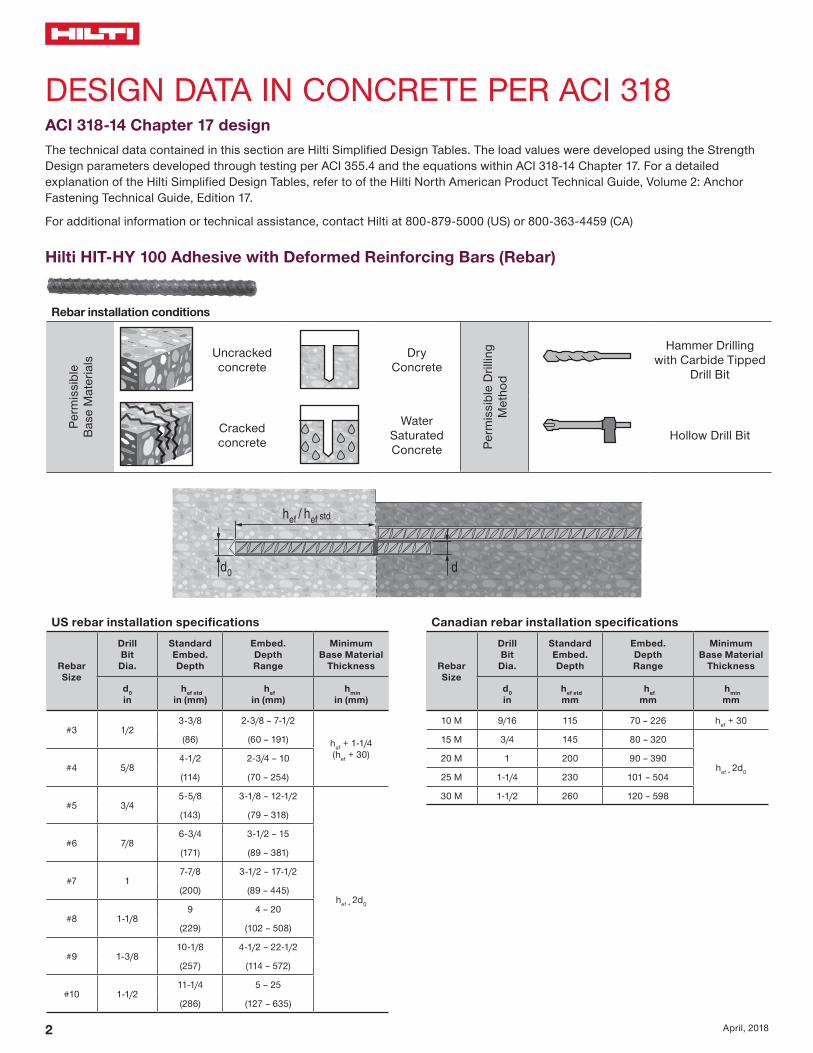
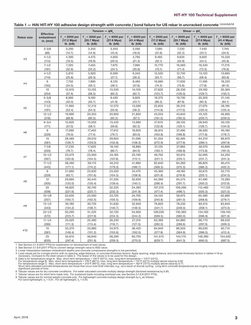
HIT-HY 100 Technical Supplement
3April 2018
Table 1 mdash Hilti HIT-HY 100 adhesive design strength with concrete bond failure for US rebar in uncracked concrete 12345678
Rebar sizeEffective
embedmentin (mm)
Tension mdash ϕNn Shear mdash ϕVn
f c = 2500 psi(172 Mpa)
lb (kN)
f c = 3000 psi(207 Mpa)
lb (kN)
f c = 4000 psi(276 Mpa)
lb (kN)
f c = 6000 psi(414 Mpa)
lb (kN)
f c = 2500 psi(172 Mpa)
lb (kN)
f c = 3000 psi(207 Mpa)
lb (kN)
f c = 4000 psi(276 Mpa)
lb (kN)
f c = 6000 psi(414 Mpa)
lb (kN)
3
3-38 3295 3355 3455 3595 7095 7230 7440 7745(86) (147) (149) (154) (160) (316) (322) (331) (345)
4-12 4395 4475 4605 4795 9465 9635 9920 10330(114) (195) (199) (205) (213) (421) (429) (441) (459)7-12 7325 7455 7675 7995 15770 16060 16530 17215(191) (326) (332) (341) (356) (701) (714) (735) (766)
4
4-12 5810 5920 6090 6345 12520 12750 13120 13665(114) (258) (263) (271) (282) (557) (567) (584) (608)
6 7750 7890 8120 8460 16690 17000 17495 18220(152) (345) (351) (361) (376) (742) (756) (778) (810)10 12915 13155 13535 14100 27820 28330 29160 30365
(254) (574) (585) (602) (627) (1237) (1260) (1297) (1351)
5
5-58 8995 9160 9430 9820 19375 19730 20305 21145(143) (400) (407) (419) (437) (862) (878) (903) (941)7-12 11995 12215 12570 13090 25835 26310 27075 28195(191) (534) (543) (559) (582) (1149) (1170) (1204) (1254)
12-12 19990 20355 20950 21820 43055 43845 45125 46995(318) (889) (905) (932) (971) (1915) (1950) (2007) (2090)
6
6-34 12820 13055 13435 13990 27610 28120 28940 30135(171) (570) (581) (598) (622) (1228) (1251) (1287) (1340)
9 17090 17405 17915 18655 36815 37490 38585 40180(229) (760) (774) (797) (830) (1638) (1668) (1716) (1787)
15 28485 29010 29855 31095 61355 62485 64310 66970(381) (1267) (1290) (1328) (1383) (2729) (2779) (2861) (2979)
7
7-78 17235 17625 18140 18890 37125 37965 39070 40690(200) (767) (784) (807) (840) (1651) (1689) (1738) (1810)
10-12 23075 23500 24185 25190 49705 50615 52095 54250(267) (1026) (1045) (1076) (1121) (2211) (2251) (2317) (2413)17-12 38460 39170 40310 41980 82840 84360 86825 90415(445) (1711) (1742) (1793) (1867) (3685) (3753) (3862) (4022)
8
9 21060 22835 23500 24475 45360 49180 50615 52710(229) (937) (1016) (1045) (1089) (2018) (2188) (2251) (2345)
12 29895 30445 31335 32630 64390 65575 67490 70280(305) (1330) (1354) (1394) (1451) (2864) (2917) (3002) (3126)
20 49825 50740 52225 54385 107315 109290 112480 117135(508) (2216) (2257) (2323) (2419) (4774) (4861) (5003) (5210)
9
10-18 22635 23050 23725 24705 54125 58675 60385 62885(257) (1007) (1025) (1055) (1099) (2408) (2610) (2686) (2797)
13-12 30180 30735 31630 32940 76820 78230 80515 83845(343) (1342) (1367) (1407) (1465) (3417) (3480) (3581) (3730)
22-12 50295 51225 52720 54900 128030 130385 134190 139745(572) (2237) (2279) (2345) (2442) (5695) (5800) (5969) (6216)
10
11-14 25025 25490 26230 27315 63395 64880 66770 69535(286) (1113) (1134) (1167) (1215) (2820) (2886) (2970) (3093)
15 33370 33985 34975 36425 84940 86505 89030 92710(381) (1484) (1512) (1556) (1620) (3778) (3848) (3960) (4124)25 55615 56640 58290 60705 141570 144175 148380 154520
(635) (2474) (2519) (2593) (2700) (6297) (6413) (6600) (6873)1 See Section 318 (2017 PTG) for explanation on development of load values2 See Section 3186 (2017 PTG) to convert design strength value to ASD value3 Linear interpolation between embedment depths and concrete compressive strengths is not permitted4 Load values are for a single anchor with no spacing edge distance or concrete thickness factors Apply spacing edge distance and concrete thickness factors in tables 4-19 as
necessary Compare to the steel values in table 3 The lesser of the values is to be used for the design5 Data is for temperature range A Max short term temperature = 130degF (55degC) max long term temperature = 110degF (43degC)
For temperature range B Max short term temperature = 176degF (80degC) max long term temperature = 110degF (43degC) multiply above value by 092 For temperature range C Max short term temperature = 210degF (99degC) max long term temperature = 162degF (72degC) multiply above value by 071 Short term elevated concrete temperatures are those that occur over brief intervals eg as a result of diurnal cycling Long term concrete temperatures are roughly constant over significant periods of time
6 Tabular values are for dry concrete conditions For water saturated concrete multiply design strength (factored resistance) by 0857 Tabular values are for short term loads only For sustained loads including overhead use see Section 3188 (2017 PTG)8 Tabular values are for normal-weight concrete only For lightweight concrete multiply design strength by λa as follows
For sand-lightweight λa = 051 For all-lightweight λa = 045
4 April 2018
Table 2 mdash Hilti HIT-HY 100 adhesive design strength with concrete bond failure for US rebar in cracked concrete 12345678
Rebar sizeEffective
embedmentin (mm)
Tension mdash ϕNn Shear mdash ϕVn
f´c = 2500 psi(172 Mpa)
lb (kN)
f´c = 3000 psi(207 Mpa)
lb (kN)
f´c = 4000 psi(276 Mpa)
lb (kN)
f´c = 6000 psi(414 Mpa)
lb (kN)
f´c = 2500 psi(172 Mpa)
lb (kN)
f´c = 3000 psi(207 Mpa)
lb (kN)
f´c = 4000 psi(276 Mpa)
lb (kN)
f´c = 6000 psi(414 Mpa)
lb (kN)
3
3-38 1575 1605 1650 1720 3395 3460 3560 3705(86) (70) (71) (73) (77) (151) (154) (158) (165)
4-12 2100 2140 2205 2295 4525 4610 4745 4940(114) (93) (95) (98) (102) (201) (205) (211) (220)7-12 3505 3570 3670 3825 7545 7685 7910 8235(191) (156) (159) (163) (170) (336) (342) (352) (366)
4
4-12 3080 3135 3225 3360 6630 6750 6950 7235(114) (137) (139) (143) (149) (295) (300) (309) (322)
6 4105 4180 4300 4480 8840 9005 9265 9650(152) (183) (186) (191) (199) (393) (401) (412) (429)10 6840 6965 7170 7465 14735 15005 15445 16080
(254) (304) (310) (319) (332) (655) (667) (687) (715)
5
5-58 5205 5300 5455 5680 11210 11415 11750 12235(143) (232) (236) (243) (253) (499) (508) (523) (544)7-12 6940 7065 7275 7575 14945 15220 15665 16315(191) (309) (314) (324) (337) (665) (677) (697) (726)
12-12 11565 11780 12125 12625 24910 25370 26110 27190(318) (514) (524) (539) (562) (1108) (1129) (1161) (1209)
6
6-34 8010 8160 8395 8745 17255 17575 18085 18835(171) (356) (363) (373) (389) (768) (782) (804) (838)
9 10680 10880 11195 11660 23010 23430 24115 25115(229) (475) (484) (498) (519) (1024) (1042) (1073) (1117)
15 17805 18130 18660 19435 38345 39055 40190 41855(381) (792) (806) (830) (865) (1706) (1737) (1788) (1862)
7
7-78 10975 11175 11505 11980 23640 24075 24775 25800(200) (488) (497) (512) (533) (1052) (1071) (1102) (1148)
10-12 14635 14905 15340 15975 31520 32100 33035 34405(267) (651) (663) (682) (711) (1402) (1428) (1469) (1530)17-12 24390 24840 25565 26620 52530 53500 55060 57340(445) (1085) (1105) (1137) (1184) (2337) (2380) (2449) (2551)
8
9 14520 14785 15220 15845 31270 31845 32775 34135(229) (646) (658) (677) (705) (1391) (1417) (1458) (1518)
12 19360 19715 20290 21130 41695 42460 43700 45510(305) (861) (877) (903) (940) (1855) (1889) (1944) (2024)
20 32265 32860 33815 35215 69490 70770 72835 75850(508) (1435) (1462) (1504) (1566) (3091) (3148) (3240) (3374)
9
10-18 15645 15935 16400 17080 38340 40560 41745 43470(257) (696) (709) (730) (760) (1705) (1804) (1857) (1934)
13-12 20860 21245 21865 22770 53105 54080 55660 57965(343) (928) (945) (973) (1013) (2362) (2406) (2476) (2578)
22-12 34770 35410 36445 37950 88510 90135 92765 96605(572) (1547) (1575) (1621) (1688) (3937) (4009) (4126) (4297)
10
11-14 19560 19920 20500 21350 44905 49190 52185 54345(286) (870) (886) (912) (950) (1997) (2188) (2321) (2417)
15 26080 26560 27335 28465 66385 67605 69580 72460(381) (1160) (1181) (1216) (1266) (2953) (3007) (3095) (3223)25 43465 44265 45560 47445 110645 112680 115965 120765
(635) (1921) (1957) (2014) (2097) (4891) (4981) (5126) (5339)1 See Section 318 (2017 PTG) for explanation on development of load values2 See Section 3186 (2017 PTG) to convert design strength value to ASD value3 Linear interpolation between embedment depths and concrete compressive strengths is not permitted4 Load values are for a single anchor with no spacing edge distance or concrete thickness factors Apply spacing edge distance and concrete thickness factors in tables 4-19 as
necessary Compare to the steel values in table 3 The lesser of the values is to be used for the design5 Data is for temperature range A Max short term temperature = 104degF (40degC) max long term temperature = 75degF (24degC)
For temperature range B Max short term temperature = 176degF (80degC) max long term temperature = 110degF (43degC) multiply above value by 092 For temperature range C Max short term temperature = 210degF (99degC) max long term temperature = 162degF (72degC) multiply above value by 071 Short term elevated concrete temperatures are those that occur over brief intervals eg as a result of diurnal cycling Long term concrete temperatures are roughly constant over significant periods of time
6 Tabular values are for dry concrete conditions For water saturated concrete multiply design strength (factored resistance) by 0857 Tabular values are for short term loads only For sustained loads including overhead use see Section 3188 (2017 PTG)8 Tabular values are for normal-weight concrete only For lightweight concrete multiply design strength by λa as follows
For sand-lightweight λa = 051 For all-lightweight λa = 0459 Tabular values are for static loads only For seismic loads multiply cracked concrete tabular values in tension and shear by αseis = 075 See section 3187 (2017 PTG) for additional information on seismic applications
HIT-HY 100 Technical Supplement
5April 2018
Table 3 mdash Steel design strength for US rebar 12
Rebar size
ASTM A 615 Grade 40 ASTM A 615 Grade 60 ASTM A 706 Grade 60
Tensile3
ϕNsalb (kN)
Shear4
ϕVsalb (kN)
Seismic Shear5
ϕVsaeqlb (kN)
Tensile3
ϕNsalb (kN)
Shear4
ϕVsalb (kN)
Seismic Shear5
ϕVsaeqlb (kN)
Tensile3
ϕNsalb (kN)
Shear4
ϕVsalb (kN)
Seismic Shear5
ϕVsaeqlb (kN)
34290 2375 1665 6435 3565 2495 6600 3430 2400(191) (106) (74) (286) (159) (111) (294) (153) (107)
47800 4320 3025 11700 6480 4535 12000 6240 4370(347) (192) (135) (520) (288) (202) (534) (278) (194)
512090 6695 4685 18135 10045 7030 18600 9670 6770(538) (298) (208) (807) (447) (313) (827) (430) (301)
617160 9505 6655 25740 14255 9980 26400 13730 9610(763) (423) (296) (1145) (634) (444) (1174) (611) (427)
723400 12960 9070 35100 19440 13610 36000 18720 13105(1041) (576) (403) (1561) (865) (605) (1601) (833) (583)
830810 17065 11945 46215 25595 17915 47400 24650 17255(1370) (759) (531) (2056) (1139) (797) (2108) (1096) (768)
939000 21600 15120 58500 32400 22680 60000 31200 21840(1735) (961) (673) (2602) (1441) (1009) (2669) (1388) (971)
1049530 27430 19200 74295 41150 28805 76200 39625 27740(2203) (1220) (854) (3305) (1830) (1281) (3390) (1763) (1234)
1 See Section 3186 (2017 PTG) to convert design strength value to ASD value2 ASTM A706 Grade 60 rebar are considered ductile steel elements ASTM A 615 Grade 40 and 60 rebar are considered brittle steel elements3 Tensile = ϕ AseN futa as noted in ACI 318 Chapter 174 Shear = ϕ 060 AseN futa as noted in ACI 318 Chapter 175 Seismic Shear = αVseis ϕVsa Reduction for seismic shear only See section 3187 (2017 PTG) for additional information on seismic applications
6 April 2018
Table 4 mdash Load adjustment factors for 3 rebar in uncracked concrete 123
3Uncracked concrete
Spacing factor in tension
fAN
Edge distance factor in tension
fRN
Spacing factor in shear 4
fAV
Edge distance in shearConcrete thickness
factor in shear 5
fHV
Toward edge
fRV
To edge
fRV
Embedment hefin (mm)
3-38 4-12 7-12 3-38 4-12 7-12 3-38 4-12 7-12 3-38 4-12 7-12 3-38 4-12 7-12 3-38 4-12 7-12(86) (114) (191) (86) (114) (191) (86) (114) (191) (86) (114) (191) (86) (114) (191) (86) (114) (191)
Spac
ing
(s)
edg
e di
stan
ce (c
a) c
oncr
ete
thic
knes
s (h
) - i
n (m
m)
1-34 (44) na na na 032 023 013 na na na 010 008 005 021 016 009 na na na1-78 (48) 059 057 054 033 024 014 054 053 052 012 009 005 023 017 010 na na na
2 (51) 060 057 054 034 025 014 054 053 052 013 010 006 025 019 011 na na na3 (76) 065 061 057 042 031 018 056 055 054 023 017 010 042 031 018 na na na4 (102) 070 065 059 052 038 022 058 057 055 036 027 016 052 038 022 na na na
4-58 (117) 073 067 060 060 043 025 060 058 056 045 033 020 060 043 025 062 na na5 (127) 075 069 061 064 047 027 061 059 056 050 038 023 064 047 027 065 na na
5-34 (146) 078 071 063 074 054 031 062 060 057 062 046 028 074 054 031 070 063 na6 (152) 080 072 063 077 056 033 063 060 057 066 049 030 077 056 033 071 065 na7 (178) 085 076 066 090 066 038 065 062 059 083 062 037 090 066 038 077 070 na8 (203) 090 080 068 100 075 043 067 064 060 100 076 046 100 075 043 082 075 na
8-34 (222) 093 082 069 082 048 068 065 061 087 052 082 048 086 078 0669 (229) 094 083 070 084 049 069 066 061 091 055 084 049 087 079 06710 (254) 099 087 072 094 054 071 067 062 100 064 094 054 092 083 07011 (279) 100 091 074 100 060 073 069 064 074 100 060 096 087 07412 (305) 094 077 065 075 071 065 084 065 100 091 07714 (356) 100 081 076 079 074 067 100 076 099 08316 (406) 086 087 084 078 070 087 100 08918 (457) 090 098 088 081 072 098 09424 (610) 100 100 100 092 080 100 10030 (762) 100 08736 (914) 094
gt 48 (1219) 100
Table 5 mdash Load adjustment factors for 3 rebar in cracked concrete 123
3Cracked concrete
Spacing factor in tension
fAN
Edge distance factor in tension
fRN
Spacing factor in shear 4
fAV
Edge distance in shearConcrete thickness
factor in shear 5
fHV
Toward edge
fRV
To edge
fRV
Embedment hefin (mm)
3-38 4-12 7-12 3-38 4-12 7-12 3-38 4-12 7-12 3-38 4-12 7-12 3-38 4-12 7-12 3-38 4-12 7-12(86) (114) (191) (86) (114) (191) (86) (114) (191) (86) (114) (191) (86) (114) (191) (86) (114) (191)
Spac
ing
(s)
edg
e di
stan
ce (c
a) c
oncr
ete
thic
knes
s (h
) - i
n (m
m)
1-34 (44) na na na 054 049 043 na na na 010 007 004 020 015 009 na na na1-78 (48) 059 057 054 056 050 044 054 053 052 011 008 005 022 017 010 na na na
2 (51) 060 057 054 057 051 044 054 053 052 012 009 005 024 018 011 na na na3 (76) 065 061 057 070 060 049 056 055 054 022 017 010 045 034 020 na na na4 (102) 070 065 059 084 070 055 058 057 055 034 026 015 069 052 031 na na na
4-58 (117) 073 067 060 093 076 058 059 058 056 043 032 019 086 064 038 062 na na5 (127) 075 069 061 099 080 060 060 058 056 048 036 022 096 072 043 064 na na
5-34 (146) 078 071 063 100 088 064 062 060 057 059 044 027 100 088 053 069 062 na6 (152) 080 072 063 091 066 062 060 057 063 047 028 091 057 070 064 na7 (178) 085 076 066 100 072 064 062 058 080 060 036 100 072 076 069 na8 (203) 090 080 068 078 066 064 060 097 073 044 078 081 074 na
8-34 (222) 093 082 069 083 068 065 061 100 083 050 083 085 077 0659 (229) 094 083 070 085 068 065 061 087 052 085 086 078 06610 (254) 099 087 072 091 070 067 062 100 061 091 090 082 06911 (279) 100 091 074 098 073 069 063 071 098 095 086 07312 (305) 094 077 100 075 070 064 080 100 099 090 07614 (356) 100 081 100 079 074 067 100 100 097 08216 (406) 086 083 077 069 100 08818 (457) 090 087 080 072 09324 (610) 100 099 091 079 10030 (762) 100 100 08636 (914) 093
gt 48 (1219) 1001 Linear interpolation not permitted2 Shaded area with reduced edge distance is permitted provided the rebar has no installation torque3 When combining multiple load adjustment factors (eg for a four-anchor pattern in a corner with thin concrete member) the design can become very conservative To optimize the design
use Hilti PROFIS Anchor Design software or perform anchor calculation using design equations from ACI 318 Chapter 174 Spacing factor reduction in shear applicable when ca lt 3hef ƒAV is applicable when edge distance ca lt 3hef If ca ge 3hef then ƒAV = ƒAN 5 Concrete thickness reduction factor in shear ƒHV is applicable when edge distance ca lt 3hef If ca ge 3hef then ƒHV = 10
HIT-HY 100 Technical Supplement
7April 2018
Table 6 mdash Load adjustment factors for 4 rebar in uncracked concrete 123
4Uncracked concrete
Spacing factor in tension
fAN
Edge distance factor in tension
fRN
Spacing factor in shear 4
fAV
Edge distance in shearConcrete thickness
factor in shear 5
fHV
Toward edge
fRV
To edge
fRV
Embedment hefin (mm)
4-12 6 10 4-12 6 10 4-12 6 10 4-12 6 10 4-12 6 10 4-12 6 10 (114) (152) (254) (114) (152) (254) (114) (152) (254) (114) (152) (254) (114) (152) (254) (114) (152) (254)
Spac
ing
(s)
edg
e di
stan
ce (c
a) c
oncr
ete
thic
knes
s (h
) - i
n (m
m)
1-34 (44) na na na 027 020 012 na na na 007 005 003 014 010 006 na na na2-12 (64) 059 057 054 032 023 014 054 053 052 012 009 005 023 017 010 na na na
3 (76) 061 058 055 035 026 015 055 054 053 015 011 007 031 023 014 na na na4 (102) 065 061 057 041 030 018 056 055 054 023 018 011 041 030 018 na na na5 (127) 069 064 058 048 035 021 058 057 055 033 025 015 048 035 021 na na na
5-34 (146) 071 066 060 054 040 023 059 058 055 040 030 018 054 040 023 060 na na6 (152) 072 067 060 056 041 024 060 058 056 043 032 019 056 041 024 062 na na7 (178) 076 069 062 066 048 028 061 059 057 054 041 024 066 048 028 067 na na
7-14 (184) 077 070 062 068 050 029 062 059 057 057 043 026 068 050 029 068 062 na8 (203) 080 072 063 075 055 032 063 060 057 066 050 030 075 055 032 071 065 na9 (229) 083 075 065 085 062 036 064 062 058 079 059 036 085 062 036 076 069 na10 (254) 087 078 067 094 069 040 066 063 059 093 070 042 094 069 040 080 072 na
11-14 (286) 092 081 069 100 078 045 068 065 060 100 083 050 100 078 045 084 077 06512 (305) 094 083 070 083 048 069 066 061 092 055 083 048 087 079 06714 (356) 100 089 073 097 056 072 068 063 100 069 097 056 094 086 07216 (406) 094 077 100 065 075 071 065 085 100 065 100 092 07718 (457) 100 080 073 079 074 067 100 073 097 08220 (508) 083 081 082 076 069 081 100 08622 (559) 087 089 085 079 070 089 09124 (610) 090 097 088 081 072 097 09530 (762) 100 100 098 089 078 100 10036 (914) 100 097 084
gt 48 (1219) 100 095
Table 7 mdash Load adjustment factors for 4 rebar in cracked concrete 123
4Cracked concrete
Spacing factor in tension
fAN
Edge distance factor in tension
fRN
Spacing factor in shear 4
fAV
Edge distance in shearConcrete thickness
factor in shear 5
fHV
Toward edge
fRV
To edge
fRV
Embedment hefin (mm)
4-12 6 10 4-12 6 10 4-12 6 10 4-12 6 10 4-12 6 10 4-12 6 10 (114) (152) (254) (114) (152) (254) (114) (152) (254) (114) (152) (254) (114) (152) (254) (114) (152) (254)
Spac
ing
(s)
edg
e di
stan
ce (c
a) c
oncr
ete
thic
knes
s (h
) - i
n (m
m)
1-34 (44) na na na 049 045 041 na na na 006 005 003 013 010 006 na na na2-12 (64) 059 057 054 056 050 044 054 053 052 011 008 005 022 017 010 na na na
3 (76) 061 058 055 060 053 046 055 054 053 015 011 007 029 022 013 na na na4 (102) 065 061 057 070 060 049 056 055 054 022 017 010 045 034 020 na na na5 (127) 069 064 058 080 067 053 058 056 055 031 023 014 062 047 028 na na na
5-34 (146) 071 066 060 088 073 056 059 057 055 039 029 017 077 058 035 059 na na6 (152) 072 067 060 091 075 057 059 058 055 041 031 018 082 062 037 061 na na7 (178) 076 069 062 100 083 062 061 059 056 052 039 023 100 078 047 066 na na
7-14 (184) 077 070 062 085 063 061 059 057 055 041 025 082 049 067 061 na8 (203) 080 072 063 091 066 062 060 057 063 047 028 091 057 070 064 na9 (229) 083 075 065 100 070 064 061 058 075 057 034 100 068 074 068 na10 (254) 087 078 067 075 065 063 059 088 066 040 075 078 071 na
11-14 (286) 092 081 069 081 067 064 060 100 079 047 081 083 075 06412 (305) 094 083 070 085 068 065 061 087 052 085 086 078 06614 (356) 100 089 073 095 071 068 063 100 066 095 093 084 07116 (406) 094 077 100 075 070 064 080 100 099 090 07618 (457) 100 080 078 073 066 096 100 095 08120 (508) 083 081 075 068 100 100 08522 (559) 087 084 078 070 08924 (610) 090 087 080 072 09330 (762) 100 096 088 077 10036 (914) 100 096 082
gt 48 (1219) 100 0931 Linear interpolation not permitted2 Shaded area with reduced edge distance is permitted provided the rebar has no installation torque3 When combining multiple load adjustment factors (eg for a four-anchor pattern in a corner with thin concrete member) the design can become very conservative To optimize the design
use Hilti PROFIS Anchor Design software or perform anchor calculation using design equations from ACI 318 Chapter 174 Spacing factor reduction in shear applicable when ca lt 3hef ƒAV is applicable when edge distance ca lt 3hef If ca ge 3hef then ƒAV = ƒAN 5 Concrete thickness reduction factor in shear ƒHV is applicable when edge distance ca lt 3hef If ca ge 3hef then ƒHV = 10
8 April 2018
Table 8 mdash Load adjustment factors for 5 rebar in uncracked concrete 123
5Uncracked concrete
Spacing factor in tension
fAN
Edge distance factor in tension
fRN
Spacing factor in shear 4
fAV
Edge distance in shearConcrete thickness
factor in shear 5
fHV
Toward edge
fRV
To edge
fRV
Embedment hefin (mm)
5-58 7-12 12-12 5-58 7-12 12-12 5-58 7-12 12-12 5-58 7-12 12-12 5-58 7-12 12-12 5-58 7-12 12-12(143) (191) (318) (143) (191) (318) (143) (191) (318) (143) (191) (318) (143) (191) (318) (143) (191) (318)
Spac
ing
(s)
edg
e di
stan
ce (c
a) c
oncr
ete
thic
knes
s (h
) - i
n (m
m)
1-34 (44) na na na 025 019 011 na na na 005 004 002 010 007 004 na na na2-12 (64) 059 057 054 032 023 014 054 053 052 012 009 005 023 018 011 na na na
3 (76) 062 059 055 036 026 015 055 054 053 017 013 008 034 025 015 na na na4 (102) 065 061 057 041 030 018 056 055 054 024 018 011 041 030 018 na na na5 (127) 068 063 058 047 034 020 058 056 055 031 023 014 047 034 020 na na na
5-34 (146) 071 066 059 053 039 023 059 057 055 039 029 018 053 039 023 na na na6 (152) 071 066 060 054 039 023 059 058 055 040 030 018 054 039 023 060 na na7 (178) 074 068 061 060 044 026 060 058 056 048 036 022 060 044 026 064 na na
7-14 (184) 077 070 062 068 050 029 061 059 057 057 043 026 068 050 029 068 062 na8 (203) 080 072 063 075 055 032 063 061 058 067 050 030 075 055 032 071 065 na9 (229) 083 074 065 083 061 036 064 062 058 077 058 035 083 061 036 075 068 na10 (254) 086 077 066 090 066 039 065 063 059 088 066 040 090 066 039 078 071 na
11-14 (286) 091 081 069 100 077 045 068 065 061 100 083 050 100 077 045 085 077 06512 (305) 097 086 071 088 052 070 067 062 100 061 088 052 090 082 06914 (356) 100 090 074 099 058 073 069 064 073 099 058 096 087 07316 (406) 094 077 100 065 076 071 065 085 100 065 100 092 07718 (457) 099 079 071 078 073 067 099 071 096 08120 (508) 100 082 078 081 075 068 100 078 100 08522 (559) 085 084 083 077 070 084 08824 (610) 087 091 086 080 071 091 09230 (762) 090 097 088 082 073 097 09536 (914) 098 100 096 088 077 100 100
gt 48 (1219) 100 100 100 086
Table 9 mdash Load adjustment factors for 5 rebar in cracked concrete 123
5Cracked concrete
Spacing factor in tension
fAN
Edge distance factor in tension
fRN
Spacing factor in shear 4
fAV
Edge distance in shearConcrete thickness
factor in shear 5
fHV
Toward edge
fRV
To edge
fRV
Embedment hefin (mm)
5-58 7-12 12-12 5-58 7-12 12-12 5-58 7-12 12-12 5-58 7-12 12-12 5-58 7-12 12-12 5-58 7-12 12-12(143) (191) (318) (143) (191) (318) (143) (191) (318) (143) (191) (318) (143) (191) (318) (143) (191) (318)
Spac
ing
(s)
edg
e di
stan
ce (c
a) c
oncr
ete
thic
knes
s (h
) - i
n (m
m)
1-34 (44) na na na 046 043 040 na na na 005 003 002 009 007 004 na na na2-12 (64) 059 057 054 056 050 044 054 053 052 011 008 005 022 017 010 na na na
3 (76) 062 059 055 062 055 046 055 054 053 016 012 007 032 024 014 na na na4 (102) 065 061 057 070 060 049 056 055 054 022 017 010 045 034 020 na na na5 (127) 068 063 058 078 066 053 057 056 054 029 022 013 059 044 026 na na na
5-34 (146) 071 066 059 087 072 056 059 057 055 037 028 017 074 056 033 na na na6 (152) 071 066 060 088 073 056 059 057 055 038 029 017 076 057 034 059 na na7 (178) 074 068 061 096 078 059 060 058 056 045 034 020 090 068 041 063 na na
7-14 (184) 077 070 062 100 085 062 061 059 056 054 040 024 100 081 049 066 060 na8 (203) 080 072 063 091 066 062 060 057 063 047 028 091 057 070 064 na9 (229) 083 074 065 098 069 064 061 058 073 055 033 098 066 073 067 na10 (254) 086 077 066 100 073 065 062 059 083 062 037 100 073 077 070 na
11-14 (286) 091 081 069 081 067 064 060 100 079 047 081 083 075 06412 (305) 097 086 071 089 070 066 062 096 058 089 089 081 06814 (356) 100 090 074 097 072 068 063 100 069 097 094 085 07216 (406) 094 077 100 075 070 064 080 100 099 090 07618 (457) 099 079 077 072 066 093 100 094 08020 (508) 100 082 079 074 067 100 099 08322 (559) 085 082 076 069 100 08724 (610) 087 084 078 070 09030 (762) 090 087 080 072 09336 (914) 098 094 086 076 100
gt 48 (1219) 100 100 099 0851 Linear interpolation not permitted2 Shaded area with reduced edge distance is permitted provided the rebar has no installation torque3 When combining multiple load adjustment factors (eg for a four-anchor pattern in a corner with thin concrete member) the design can become very conservative To optimize the design
use Hilti PROFIS Anchor Design software or perform anchor calculation using design equations from ACI 318 Chapter 174 Spacing factor reduction in shear applicable when ca lt 3hef ƒAV is applicable when edge distance ca lt 3hef If ca ge 3hef then ƒAV = ƒAN 5 Concrete thickness reduction factor in shear ƒHV is applicable when edge distance ca lt 3hef If ca ge 3hef then ƒHV = 10
HIT-HY 100 Technical Supplement
9April 2018
Table 10 mdash Load adjustment factors for 6 rebar in uncracked concrete 123
6Uncracked concrete
Spacing factor in tension
fAN
Edge distance factor in tension
fRN
Spacing factor in shear 4
fAV
Edge distance in shearConcrete thickness
factor in shear 5
fHV
Toward edge
fRV
To edge
fRV
Embedment hefin (mm)
6-34 9 15 6-34 9 15 6-34 9 15 6-34 9 15 6-34 9 15 6-34 9 15 (171) (229) (381) (171) (229) (381) (171) (229) (381) (171) (229) (381) (171) (229) (381) (171) (229) (381)
Spac
ing
(s)
edg
e di
stan
ce (c
a) c
oncr
ete
thic
knes
s (h
) - i
n (m
m)
1-34 (44) na na na 024 018 010 na na na 004 003 002 007 006 003 na na na3-34 (95) 059 057 054 032 023 014 054 053 052 012 009 005 023 017 010 na na na
4 (102) 060 057 054 033 024 014 054 053 052 013 010 006 026 019 012 na na na5 (127) 062 059 056 037 027 016 055 054 053 018 013 008 036 027 016 na na na6 (152) 065 061 057 041 030 018 056 055 054 023 018 011 041 030 018 na na na8 (203) 070 065 059 051 037 022 058 057 055 036 027 016 051 037 022 na na na
8-12 (216) 071 066 059 053 039 023 059 057 055 040 030 018 053 039 023 060 na na10 (254) 075 069 061 063 046 027 061 059 056 051 038 023 063 046 027 065 na na
10-34 (273) 077 070 062 068 050 029 061 059 057 056 042 025 068 050 029 067 061 na12 (305) 080 072 063 075 055 032 063 060 057 066 050 030 075 055 032 071 065 na14 (356) 085 076 066 088 065 038 065 062 059 084 063 038 088 065 038 077 070 na16 (406) 090 080 068 100 074 043 067 064 060 100 077 046 100 074 043 082 075 na
16-34 (425) 091 081 069 077 045 068 065 060 082 049 077 045 084 076 06418 (457) 094 083 070 083 049 069 066 061 091 055 083 049 087 079 06720 (508) 099 087 072 092 054 071 067 062 100 064 092 054 092 084 07022 (559) 100 091 074 100 059 073 069 064 074 100 059 096 088 07424 (610) 094 077 065 075 071 065 085 065 100 092 07726 (660) 098 079 070 077 073 066 095 070 095 08028 (711) 100 081 076 080 074 067 100 076 099 08330 (762) 083 081 082 076 069 081 100 08636 (914) 090 097 088 081 072 097 095
gt 48 (1219) 100 100 100 092 080 100 100
Table 11 mdash Load adjustment factors for 6 rebar in cracked concrete 123
6Cracked concrete
Spacing factor in tension
fAN
Edge distance factor in tension
fRN
Spacing factor in shear 4
fAV
Edge distance in shearConcrete thickness
factor in shear 5
fHV
Toward edge
fRV
To edge
fRV
Embedment hefin (mm)
6-34 9 15 6-34 9 15 6-34 9 15 6-34 9 15 6-34 9 15 6-34 9 15 (171) (229) (381) (171) (229) (381) (171) (229) (381) (171) (229) (381) (171) (229) (381) (171) (229) (381)
Spac
ing
(s)
edg
e di
stan
ce (c
a) c
oncr
ete
thic
knes
s (h
) - i
n (m
m)
1-34 (44) na na na 044 042 039 na na na 003 003 002 007 005 003 na na na3-34 (95) 059 057 054 056 050 044 054 053 052 011 008 005 022 016 010 na na na
4 (102) 060 057 054 057 051 044 054 053 052 012 009 005 024 018 011 na na na5 (127) 062 059 056 063 056 047 055 054 053 017 012 007 034 025 015 na na na6 (152) 065 061 057 070 060 049 056 055 054 022 016 010 044 033 020 na na na8 (203) 070 065 059 084 070 055 058 057 055 034 025 015 068 051 030 na na na
8-12 (216) 071 066 059 088 072 056 059 057 055 037 028 017 075 055 033 059 na na10 (254) 075 069 061 099 080 060 060 058 056 048 035 021 095 071 042 064 na na
10-34 (273) 077 070 062 100 084 062 061 059 056 053 039 024 100 079 047 066 060 na12 (305) 080 072 063 091 066 062 060 057 063 046 028 091 056 070 063 na14 (356) 085 076 066 100 072 064 062 058 079 059 035 100 070 076 068 na16 (406) 090 080 068 078 066 063 059 097 071 043 078 081 073 na
16-34 (425) 091 081 069 081 067 064 060 100 077 046 081 083 075 06318 (457) 094 083 070 085 068 065 061 085 051 085 086 077 06520 (508) 099 087 072 091 070 067 062 100 060 091 090 082 06922 (559) 100 091 074 098 072 068 063 069 098 095 086 07224 (610) 094 077 100 074 070 064 079 100 099 089 07526 (660) 098 079 076 072 065 089 100 093 07828 (711) 100 081 079 073 067 099 097 08130 (762) 083 081 075 068 100 100 08436 (914) 090 087 080 071 092
gt 48 (1219) 100 099 090 078 1001 Linear interpolation not permitted2 Shaded area with reduced edge distance is permitted provided the rebar has no installation torque3 When combining multiple load adjustment factors (eg for a four-anchor pattern in a corner with thin concrete member) the design can become very conservative To optimize the design
use Hilti PROFIS Anchor Design software or perform anchor calculation using design equations from ACI 318 Chapter 174 Spacing factor reduction in shear applicable when ca lt 3hef ƒAV is applicable when edge distance ca lt 3hef If ca ge 3hef then ƒAV = ƒAN 5 Concrete thickness reduction factor in shear ƒHV is applicable when edge distance ca lt 3hef If ca ge 3hef then ƒHV = 10
10 April 2018
Table 12 mdash Load adjustment factors for 7 rebar in uncracked concrete 123
7Uncracked concrete
Spacing factor in tension
fAN
Edge distance factor in tension
fRN
Spacing factor in shear 4
fAV
Edge distance in shearConcrete thickness
factor in shear 5
fHV
Toward edge
fRV
To edge
fRV
Embedment hefin (mm)
7-78 10-12 17-12 7-78 10-12 17-12 7-78 10-12 17-12 7-78 10-12 17-12 7-78 10-12 17-12 7-78 10-12 17-12(200) (267) (445) (200) (267) (445) (200) (267) (445) (200) (267) (445) (200) (267) (445) (200) (267) (445)
Spac
ing
(s)
edg
e di
stan
ce (c
a) c
oncr
ete
thic
knes
s (h
) - i
n (m
m)
1-34 (44) na na na 023 017 010 na na na 003 002 001 005 004 002 na na na4-38 (111) 059 057 054 032 023 014 054 053 052 011 008 005 022 016 010 na na na
5 (127) 061 058 055 034 025 015 054 054 053 013 010 006 027 020 012 na na na6 (152) 063 060 056 037 028 016 055 054 053 017 013 008 035 026 016 na na na7 (178) 065 061 057 041 030 018 056 055 054 022 016 010 041 030 018 na na na8 (203) 067 063 058 045 033 019 057 056 054 027 020 012 045 033 019 na na na
9-78 (251) 071 066 059 053 039 023 059 057 055 037 028 017 053 039 023 059 na na10 (254) 071 066 060 054 040 023 059 057 055 038 028 017 054 040 023 059 na na12 (305) 075 069 061 065 048 028 060 059 056 049 037 022 065 048 028 065 na na
12-12 (318) 076 070 062 067 050 029 061 059 056 052 039 024 067 050 029 066 060 na14 (356) 080 072 063 075 055 033 062 060 057 062 046 028 075 055 033 070 063 na16 (406) 084 075 065 086 063 037 064 061 058 076 057 034 086 063 037 075 068 na18 (457) 088 079 067 097 071 042 066 063 059 091 068 041 097 071 042 079 072 na
19-12 (495) 091 081 069 100 077 045 067 064 060 100 076 046 100 077 045 082 075 06320 (508) 092 082 069 079 046 067 064 060 079 048 079 046 083 076 06422 (559) 097 085 071 087 051 069 066 061 092 055 087 051 087 079 06724 (610) 100 088 073 095 056 071 067 062 100 063 095 056 091 083 07026 (660) 091 075 100 060 073 069 063 071 100 060 095 086 07328 (711) 094 077 065 074 070 064 079 065 099 089 07530 (762) 098 079 070 076 071 065 087 070 100 093 07836 (914) 100 084 084 081 076 068 100 084 100 086
gt 48 (1219) 096 100 092 084 074 100 099
Table 13 mdash Load adjustment factors for 7 rebar in cracked concrete 123
7Cracked concrete
Spacing factor in tension
fAN
Edge distance factor in tension
fRN
Spacing factor in shear 4
fAV
Edge distance in shearConcrete thickness
factor in shear 5
fHV
Toward edge
fRV
To edge
fRV
Embedment hefin (mm)
7-78 10-12 17-12 7-78 10-12 17-12 7-78 10-12 17-12 7-78 10-12 17-12 7-78 10-12 17-12 7-78 10-12 17-12(200) (267) (445) (200) (267) (445) (200) (267) (445) (200) (267) (445) (200) (267) (445) (200) (267) (445)
Spac
ing
(s)
edg
e di
stan
ce (c
a) c
oncr
ete
thic
knes
s (h
) - i
n (m
m)
1-34 (44) na na na 043 041 038 na na na 003 002 001 006 005 003 na na na4-38 (111) 059 057 054 056 050 044 054 053 052 012 009 005 024 018 011 na na na
5 (127) 061 058 055 059 052 045 055 054 053 015 011 007 029 022 013 na na na6 (152) 063 060 056 064 056 047 056 055 053 019 014 009 038 029 017 na na na7 (178) 065 061 057 070 060 049 056 055 054 024 018 011 048 036 022 na na na8 (203) 067 063 058 076 064 052 057 056 054 029 022 013 059 044 026 na na na
9-78 (251) 071 066 059 087 072 056 059 058 055 040 030 018 081 060 036 060 na na10 (254) 071 066 060 088 073 056 059 058 055 041 031 018 082 062 037 061 na na12 (305) 075 069 061 100 082 061 061 059 056 054 041 024 100 081 049 066 na na
12-12 (318) 076 070 062 084 062 062 060 057 057 043 026 100 084 052 068 062 na14 (356) 080 072 063 091 066 063 061 058 068 051 031 091 061 072 065 na16 (406) 084 075 065 100 071 065 062 059 083 062 037 100 071 077 070 na18 (457) 088 079 067 076 067 064 060 099 074 045 076 081 074 na
19-12 (495) 091 081 069 080 068 065 061 100 084 050 080 085 077 06520 (508) 092 082 069 082 068 065 061 087 052 082 086 078 06622 (559) 097 085 071 087 070 067 062 100 060 087 090 082 06924 (610) 100 088 073 093 072 068 063 069 093 094 085 07226 (660) 091 075 099 074 070 064 078 099 098 089 07528 (711) 094 077 100 076 071 065 087 100 100 092 07830 (762) 098 079 078 073 066 096 096 08136 (914) 100 084 083 077 069 100 100 088
gt 48 (1219) 096 094 086 076 1001 Linear interpolation not permitted2 Shaded area with reduced edge distance is permitted provided the rebar has no installation torque3 When combining multiple load adjustment factors (eg for a four-anchor pattern in a corner with thin concrete member) the design can become very conservative To optimize the design
use Hilti PROFIS Anchor Design software or perform anchor calculation using design equations from ACI 318 Chapter 174 Spacing factor reduction in shear applicable when ca lt 3hef ƒAV is applicable when edge distance ca lt 3hef If ca ge 3hef then ƒAV = ƒAN 5 Concrete thickness reduction factor in shear ƒHV is applicable when edge distance ca lt 3hef If ca ge 3hef then ƒHV = 10
HIT-HY 100 Technical Supplement
11April 2018
Table 14 mdash Load adjustment factors for 8 rebar in uncracked concrete 123
8Uncracked concrete
Spacing factor in tension
fAN
Edge distance factor in tension
fRN
Spacing factor in shear 4
fAV
Edge distance in shearConcrete thickness
factor in shear 5
fHV
Toward edge
fRV
To edge
fRV
Embedment hefin (mm)
9 12 20 9 12 20 9 12 20 9 12 20 9 12 20 9 12 20 (229) (305) (508) (229) (305) (508) (229) (305) (508) (229) (305) (508) (229) (305) (508) (229) (305) (508)
Spac
ing
(s)
edg
e di
stan
ce (c
a) c
oncr
ete
thic
knes
s (h
) - i
n (m
m)
1-34 (44) na na na 023 017 010 na na na 002 002 001 005 003 002 na na na5 (127) 059 057 054 032 023 014 054 053 052 011 008 005 022 015 009 na na na6 (152) 061 058 055 035 026 015 055 054 053 014 010 006 029 020 012 na na na7 (178) 063 060 056 038 028 016 055 054 053 018 013 008 036 025 015 na na na8 (203) 065 061 057 041 030 018 056 055 053 022 015 009 041 030 018 na na na9 (229) 067 063 058 045 033 019 057 055 054 026 018 011 045 033 019 na na na10 (254) 069 064 058 048 036 021 058 056 054 031 022 013 048 036 021 na na na
11-14 (286) 071 066 059 053 039 023 059 057 055 037 026 016 053 039 023 058 na na12 (305) 072 067 060 057 042 024 059 057 055 040 028 017 057 042 024 060 na na14 (356) 076 069 062 066 049 029 061 058 056 051 036 022 066 049 029 065 na na
14-14 (362) 076 070 062 067 050 029 061 059 056 052 037 022 067 050 029 066 059 na16 (406) 080 072 063 076 056 033 062 060 057 062 044 026 076 056 033 070 062 na18 (457) 083 075 065 085 063 037 064 061 058 074 052 031 085 063 037 074 066 na20 (508) 087 078 067 095 070 041 065 062 059 087 061 037 095 070 041 078 069 na22 (559) 091 081 068 100 076 045 067 063 059 100 071 042 100 076 045 082 073 na
22-14 (565) 091 081 069 077 045 067 063 060 072 043 077 045 082 073 06224 (610) 094 083 070 083 049 068 064 060 081 048 083 049 085 076 06426 (660) 098 086 072 090 053 070 066 061 091 054 090 053 089 079 06728 (711) 100 089 073 097 057 071 067 062 100 061 097 057 092 082 06930 (762) 092 075 100 061 073 068 063 068 100 061 095 085 07236 (914) 100 080 073 077 072 065 089 073 100 093 078
gt 48 (1219) 090 098 086 079 071 100 098 100 091
Table 15 mdash Load adjustment factors for 8 rebar in cracked concrete 123
8Cracked concrete
Spacing factor in tension
fAN
Edge distance factor in tension
fRN
Spacing factor in shear 4
fAV
Edge distance in shearConcrete thickness
factor in shear 5
fHV
Toward edge
fRV
To edge
fRV
Embedment hefin (mm)
9 12 20 9 12 20 9 12 20 9 12 20 9 12 20 9 12 20 (229) (305) (508) (229) (305) (508) (229) (305) (508) (229) (305) (508) (229) (305) (508) (229) (305) (508)
Spac
ing
(s)
edg
e di
stan
ce (c
a) c
oncr
ete
thic
knes
s (h
) - i
n (m
m)
1-34 (44) na na na 042 040 038 na na na 002 002 001 005 003 002 na na na5 (127) 059 057 054 056 050 044 054 053 052 011 008 005 022 017 010 na na na6 (152) 061 058 055 060 053 046 055 054 053 015 011 007 029 022 013 na na na7 (178) 063 060 056 065 057 047 055 054 053 018 014 008 037 028 017 na na na8 (203) 065 061 057 070 060 049 056 055 054 023 017 010 045 034 020 na na na9 (229) 067 063 058 075 064 051 057 056 054 027 020 012 054 040 024 na na na10 (254) 069 064 058 080 067 053 058 056 055 031 024 014 063 047 028 na na na
11-14 (286) 071 066 059 087 072 056 059 057 055 038 028 017 075 056 034 059 na na12 (305) 072 067 060 091 075 057 059 058 055 041 031 019 083 062 037 061 na na14 (356) 076 069 062 100 083 062 061 059 056 052 039 023 100 078 047 066 na na
14-14 (362) 076 070 062 084 062 061 059 056 054 040 024 080 048 066 060 na16 (406) 080 072 063 091 066 062 060 057 064 048 029 091 057 070 064 na18 (457) 083 075 065 100 070 064 061 058 076 057 034 100 068 075 068 na20 (508) 087 078 067 075 065 063 059 089 067 040 075 079 071 na22 (559) 091 081 068 080 067 064 060 100 077 046 080 082 075 na
22-14 (565) 091 081 069 080 067 064 060 078 047 080 083 075 06324 (610) 094 083 070 085 069 065 061 088 053 085 086 078 06626 (660) 098 086 072 090 070 067 062 099 059 090 090 081 06928 (711) 100 089 073 095 072 068 063 100 066 095 093 084 07130 (762) 092 075 100 073 069 064 074 100 096 087 07436 (914) 100 080 078 073 066 097 100 096 081
gt 48 (1219) 090 087 081 072 100 100 0931 Linear interpolation not permitted2 Shaded area with reduced edge distance is permitted provided the rebar has no installation torque3 When combining multiple load adjustment factors (eg for a four-anchor pattern in a corner with thin concrete member) the design can become very conservative To optimize the design
use Hilti PROFIS Anchor Design software or perform anchor calculation using design equations from ACI 318 Chapter 174 Spacing factor reduction in shear applicable when ca lt 3hef ƒAV is applicable when edge distance ca lt 3hef If ca ge 3hef then ƒAV = ƒAN 5 Concrete thickness reduction factor in shear ƒHV is applicable when edge distance ca lt 3hef If ca ge 3hef then ƒHV = 10
12 April 2018
Table 16 mdash Load adjustment factors for 9 rebar in uncracked concrete 123
9Uncracked concrete
Spacing factor in tension
fAN
Edge distance factor in tension
fRN
Spacing factor in shear 4
fAV
Edge distance in shearConcrete thickness
factor in shear 5
fHV
Toward edge
fRV
To edge
fRV
Embedment hefin (mm)
10-18 13-12 22-12 10-18 13-12 22-12 10-18 13-12 22-12 10-18 13-12 22-12 10-18 13-12 22-12 10-18 13-12 22-12(257) (343) (572) (257) (343) (572) (257) (343) (572) (257) (343) (572) (257) (343) (572) (257) (343) (572)
Spac
ing
(s)
edg
e di
stan
ce (c
a) c
oncr
ete
thic
knes
s (h
) - i
n (m
m)
1-34 (44) na na na 022 016 010 na na na 002 001 001 004 003 002 na na na5-58 (143) 059 057 054 032 024 014 054 053 052 011 008 005 022 015 009 na na na
6 (152) 060 057 054 033 024 014 054 053 052 012 008 005 024 017 010 na na na7 (178) 062 059 055 036 026 015 055 054 053 015 011 006 030 021 013 na na na8 (203) 063 060 056 039 029 017 055 054 053 018 013 008 037 026 016 na na na9 (229) 065 061 057 042 031 018 056 055 053 022 016 009 042 031 018 na na na10 (254) 066 062 057 045 033 019 057 055 054 026 018 011 045 033 019 na na na12 (305) 070 065 059 052 038 022 058 056 055 034 024 014 052 038 022 na na na
12-78 (327) 071 066 060 056 041 024 059 057 055 038 027 016 056 041 024 059 na na14 (356) 073 067 060 061 045 026 059 057 055 043 030 018 061 045 026 061 na na16 (406) 076 070 062 069 051 030 061 059 056 052 037 022 069 051 030 066 na na
16-14 (413) 077 070 062 070 052 030 061 059 056 053 038 023 070 052 030 066 059 na18 (457) 080 072 063 078 057 033 062 060 057 062 044 026 078 057 033 070 062 na20 (508) 083 075 065 087 064 037 063 061 058 073 051 031 087 064 037 073 065 na22 (559) 086 077 066 095 070 041 065 062 058 084 059 036 095 070 041 077 069 na24 (610) 090 080 068 100 076 045 066 063 059 096 067 040 100 076 045 080 072 na
25-14 (641) 092 081 069 080 047 067 063 060 100 073 044 080 047 083 073 06226 (660) 093 082 069 083 048 068 064 060 076 046 083 048 084 075 06328 (711) 096 085 071 089 052 069 065 061 085 051 089 052 087 077 06530 (762) 099 087 072 095 056 070 066 061 094 057 095 056 090 080 06836 (914) 100 094 077 100 067 074 069 064 100 074 100 067 099 088 074
gt 48 (1219) 100 086 100 089 082 076 068 100 089 100 100 085
Table 17 mdash Load adjustment factors for 9 rebar in cracked concrete 123
9Cracked concrete
Spacing factor in tension
fAN
Edge distance factor in tension
fRN
Spacing factor in shear 4
fAV
Edge distance in shearConcrete thickness
factor in shear 5
fHV
Toward edge
fRV
To edge
fRV
Embedment hefin (mm)
10-18 13-12 22-12 10-18 13-12 22-12 10-18 13-12 22-12 10-18 13-12 22-12 10-18 13-12 22-12 10-18 13-12 22-12(257) (343) (572) (257) (343) (572) (257) (343) (572) (257) (343) (572) (257) (343) (572) (257) (343) (572)
Spac
ing
(s)
edg
e di
stan
ce (c
a) c
oncr
ete
thic
knes
s (h
) - i
n (m
m)
1-34 (44) na na na 041 039 038 na na na 002 001 001 004 003 002 na na na5-58 (143) 059 057 054 056 050 044 054 053 052 011 008 005 022 016 009 na na na
6 (152) 060 057 054 057 051 044 054 053 052 012 009 005 024 017 010 na na na7 (178) 062 059 055 061 054 046 055 054 053 015 011 007 030 022 013 na na na8 (203) 063 060 056 065 057 048 055 054 053 019 013 008 037 027 016 na na na9 (229) 065 061 057 070 060 049 056 055 053 022 016 010 044 032 019 na na na10 (254) 066 062 057 074 063 051 057 055 054 026 019 011 052 037 022 na na na12 (305) 070 065 059 084 070 055 058 057 055 034 025 015 068 049 029 na na na
12-78 (327) 071 066 060 088 073 056 059 057 055 038 027 016 076 054 033 059 na na14 (356) 073 067 060 094 077 058 060 058 055 043 031 019 086 062 037 062 na na16 (406) 076 070 062 100 084 062 061 059 056 053 038 023 100 075 045 066 na na
16-14 (413) 077 070 062 085 063 061 059 056 054 039 023 077 046 066 059 na18 (457) 080 072 063 091 066 062 060 057 063 045 027 090 054 070 063 na20 (508) 083 075 065 099 070 064 061 058 073 053 032 099 063 074 066 na22 (559) 086 077 066 100 074 065 062 059 085 061 036 100 073 077 069 na24 (610) 090 080 068 078 066 063 059 097 069 042 078 081 072 na
25-14 (641) 092 081 069 081 067 064 060 100 075 045 081 083 074 06326 (660) 093 082 069 082 068 064 060 078 047 082 084 075 06328 (711) 096 085 071 087 069 065 061 087 052 087 087 078 06630 (762) 099 087 072 091 070 066 062 097 058 091 090 081 06836 (914) 100 094 077 100 074 070 064 100 076 100 099 088 075
gt 48 (1219) 100 086 083 076 069 100 100 100 0861 Linear interpolation not permitted2 Shaded area with reduced edge distance is permitted provided the rebar has no installation torque3 When combining multiple load adjustment factors (eg for a four-anchor pattern in a corner with thin concrete member) the design can become very conservative To optimize the design
use Hilti PROFIS Anchor Design software or perform anchor calculation using design equations from ACI 318 Chapter 174 Spacing factor reduction in shear applicable when ca lt 3hef ƒAV is applicable when edge distance ca lt 3hef If ca ge 3hef then ƒAV = ƒAN 5 Concrete thickness reduction factor in shear ƒHV is applicable when edge distance ca lt 3hef If ca ge 3hef then ƒHV = 10
HIT-HY 100 Technical Supplement
13April 2018
Table 18 mdash Load adjustment factors for 10 rebar in uncracked concrete 123
10Uncracked concrete
Spacing factor in tension
fAN
Edge distance factor in tension
fRN
Spacing factor in shear 4
fAV
Edge distance in shearConcrete thickness
factor in shear 5
fHV
Toward edge
fRV
To edge
fRV
Embedment hefin (mm)
11-14 15 25 11-14 15 25 11-14 15 25 11-14 15 25 11-14 15 25 11-14 15 25 (286) (381) (635) (286) (381) (635) (286) (381) (635) (286) (381) (635) (286) (381) (635) (286) (381) (635)
Spac
ing
(s)
edg
e di
stan
ce (c
a) c
oncr
ete
thic
knes
s (h
) - i
n (m
m) 1-34 (44) na na na 022 016 009 na na na 002 001 001 003 002 001 na na na
6-14 (159) 059 057 054 033 024 014 054 053 052 011 008 005 022 016 010 na na na7 (178) 060 058 055 035 025 015 054 053 052 013 010 006 026 019 012 na na na8 (203) 062 059 055 037 027 016 055 054 053 016 012 007 031 023 014 na na na9 (229) 063 060 056 040 030 017 055 054 053 019 014 008 038 028 017 na na na10 (254) 065 061 057 043 032 019 056 055 054 022 016 010 043 032 019 na na na11 (279) 066 062 057 046 034 020 057 055 054 025 019 011 046 034 020 na na na12 (305) 068 063 058 049 036 021 057 056 054 029 022 013 049 036 021 na na na14 (356) 071 066 059 057 042 024 059 057 055 036 027 016 057 042 024 na na na
14-14 (362) 071 066 060 058 043 025 059 057 055 037 028 017 058 043 025 059 na na16 (406) 074 068 061 065 048 028 060 058 056 045 033 020 065 048 028 062 na na17 (432) 075 069 061 069 051 030 060 058 056 049 036 022 069 051 030 064 na na18 (457) 077 070 062 073 054 031 061 059 056 053 040 024 073 054 031 066 060 na20 (508) 080 072 063 081 060 035 062 060 057 062 046 028 081 060 035 070 063 na22 (559) 083 074 065 089 066 038 063 061 058 072 054 032 089 066 038 073 066 na24 (610) 086 077 066 098 072 042 065 062 059 082 061 037 098 072 042 076 069 na26 (660) 089 079 067 100 078 045 066 063 059 092 069 041 100 078 045 079 072 na28 (711) 091 081 069 084 049 067 064 060 100 077 046 084 049 082 075 06330 (762) 094 083 070 090 052 068 065 061 085 051 090 052 085 077 06536 (914) 100 090 074 100 063 072 068 063 100 067 100 063 094 085 072
gt 48 (1219) 100 082 084 079 074 067 100 084 100 098 083
Table 19 mdash Load adjustment factors for 10 rebar in cracked concrete 123
10Cracked concrete
Spacing factor in tension
fAN
Edge distance factor in tension
fRN
Spacing factor in shear 4
fAV
Edge distance in shearConcrete thickness
factor in shear 5
fHV
Toward edge
fRV
To edge
fRV
Embedment hefin (mm)
11-14 15 25 11-14 15 25 11-14 15 25 11-14 15 25 11-14 15 25 11-14 15 25 (286) (381) (635) (286) (381) (635) (286) (381) (635) (286) (381) (635) (286) (381) (635) (286) (381) (635)
Spac
ing
(s)
edg
e di
stan
ce (c
a) c
oncr
ete
thic
knes
s (h
) - i
n (m
m) 1-34 (44) na na na 040 039 037 na na na 002 001 001 003 002 001 na na na
6-14 (159) 059 057 054 056 050 044 054 053 052 011 007 004 022 015 009 na na na7 (178) 060 058 055 058 052 045 054 053 052 013 009 005 026 018 011 na na na8 (203) 062 059 055 062 055 046 055 054 053 016 011 006 032 022 013 na na na9 (229) 063 060 056 066 057 048 055 054 053 019 013 008 038 026 015 na na na10 (254) 065 061 057 070 060 049 056 055 053 022 015 009 044 030 018 na na na11 (279) 066 062 057 074 063 051 057 055 054 026 017 010 051 035 021 na na na12 (305) 068 063 058 078 066 053 057 056 054 029 020 012 058 040 024 na na na14 (356) 071 066 059 087 072 056 059 057 055 037 025 015 073 050 030 na na na
14-14 (362) 071 066 060 088 073 056 059 057 055 038 026 015 075 051 031 059 na na16 (406) 074 068 061 096 078 059 060 058 055 045 031 018 090 061 037 063 na na17 (432) 075 069 061 100 081 061 060 058 056 049 033 020 098 067 040 064 na na18 (457) 077 070 062 085 062 061 059 056 054 036 022 100 073 044 066 058 na20 (508) 080 072 063 091 066 062 059 057 063 043 026 085 051 070 061 na22 (559) 083 074 065 098 069 063 060 057 072 049 030 098 059 073 064 na24 (610) 086 077 066 100 073 065 061 058 082 056 034 100 067 077 067 na26 (660) 089 079 067 077 066 062 059 093 063 038 076 080 070 na28 (711) 091 081 069 081 067 063 059 100 071 042 081 083 073 06130 (762) 094 083 070 085 068 064 060 078 047 085 086 075 06436 (914) 100 090 074 097 072 067 062 100 062 097 094 082 070
gt 48 (1219) 100 082 100 079 073 066 095 100 100 095 0801 Linear interpolation not permitted2 Shaded area with reduced edge distance is permitted provided the rebar has no installation torque3 When combining multiple load adjustment factors (eg for a four-anchor pattern in a corner with thin concrete member) the design can become very conservative To optimize the design
use Hilti PROFIS Anchor Design software or perform anchor calculation using design equations from ACI 318 Chapter 174 Spacing factor reduction in shear applicable when ca lt 3hef ƒAV is applicable when edge distance ca lt 3hef If ca ge 3hef then ƒAV = ƒAN 5 Concrete thickness reduction factor in shear ƒHV is applicable when edge distance ca lt 3hef If ca ge 3hef then ƒHV = 10
14 April 2018
Hilti HIT-HY 100 adhesive with Hilti HAS threaded rod
HIT-VHAS
Hilti HAS HIT-V threaded rod installation conditions
Perm
issi
ble
Bas
e M
ater
ials
Uncracked concrete
DryConcrete
Perm
issi
ble
Dril
ling
Met
hod
Hammer Drilling with Carbide Tipped
Drill Bit
Cracked concrete
Water Saturated Concrete
Hollow Drill Bit
Hilti HASHIT-V threaded rod installation specifications
Nominal Rod
Diameter
Drill Bit Diameter
Embedment Depth Range
Maximum Installation
Torque
Minimum Base Material
Thickness
din (mm)
d0in
hefin (mm)
Tmaxft-lb (Nm)
hminin (mm)
38716
2-38 ndash 7-12 15hef + 1-14 (hef + 30)
(95) (60 ndash 191) (20)12
916 2-34 ndash 10 30
(127) (70 ndash 254) (41)58
343-18 ndash 12-12 60
hef + 2d0
(159) (79 ndash 318) (81)34
783-12 ndash 15 100
(191) (89 ndash 381) (136)78
13-12 ndash 17-12 125
(222) (89 ndash 445) (169)1
1-184 ndash 20 150
(254) (102 ndash 508) (203)1-14
1-385 ndash 25 200
(318) (127 ndash 635) (271)
min
max
df HASHIT-V 38 12 58 34 78 1 1-14
df1 12 58 1316 1516 1-18 1-14 1-12
df2 716 916 1116 1316 1516 1-18 1-38 Use two washers
HIT-HY 100 Technical Supplement
15April 2018
Table 20 mdash Hilti HIT-HY 100 adhesive design strength with concrete bond failure for threaded rod in uncracked concrete 12345678
Nominal anchor
diameterin
Effective embedment
in (mm)
Tension mdash ϕNn Shear mdash ϕVn
f´c = 2500 psi(172 Mpa)
lb (kN)
f´c = 3000 psi(207 Mpa)
lb (kN)
f´c = 4000 psi(276 Mpa)
lb (kN)
f´c = 6000 psi(414 Mpa)
lb (kN)
f´c = 2500 psi(172 Mpa)
lb (kN)
f´c = 3000 psi(207 Mpa)
lb (kN)
f´c = 4000 psi(276 Mpa)
lb (kN)
f´c = 6000 psi(414 Mpa)
lb (kN)
38
2-38 2710 2760 2840 2960 2920 2970 3060 3185(60) (121) (123) (126) (132) (130) (132) (136) (142)
3-38 3850 3920 4035 4205 8295 8445 8695 9055(86) (171) (174) (179) (187) (369) (376) (387) (403)
4-12 5135 5230 5380 5605 11060 11260 11590 12070(114) (228) (233) (239) (249) (492) (501) (516) (537)7-12 8555 8715 8970 9340 18430 18770 19320 20120(191) (381) (388) (399) (415) (820) (835) (859) (895)
12
2-34 3555 3895 4385 4565 7660 8395 9445 9835(70) (158) (173) (195) (203) (341) (373) (420) (437)
4-12 6845 6970 7175 7470 14745 15015 15455 16095(114) (304) (310) (319) (332) (656) (668) (687) (716)
6 9130 9295 9565 9965 19660 20020 20605 21460(152) (406) (413) (425) (443) (875) (891) (917) (955)10 15215 15495 15945 16605 32765 33370 34345 35765
(254) (677) (689) (709) (739) (1457) (1484) (1528) (1591)
58
3-18 4310 4720 5450 6485 9280 10165 11740 13970(79) (192) (210) (242) (288) (413) (452) (522) (621)
5-58 10405 10895 11210 11675 22415 23465 24150 25145(143) (463) (485) (499) (519) (997) (1044) (1074) (1119)7-12 14260 14525 14950 15565 30720 31285 32195 33530(191) (634) (646) (665) (692) (1366) (1392) (1432) (1491)
12-12 23770 24210 24915 25945 51200 52140 53660 55880(318) (1057) (1077) (1108) (1154) (2277) (2319) (2387) (2486)
34
3-12 5105 5595 6460 7910 11000 12050 13915 17040(89) (227) (249) (287) (352) (489) (536) (619) (758)
6-34 13680 14985 16145 16815 29460 32275 34775 36210(171) (609) (667) (718) (748) (1310) (1436) (1547) (1611)
9 20540 20915 21525 22415 44235 45050 46365 48280(229) (914) (930) (957) (997) (1968) (2004) (2062) (2148)
15 34230 34860 35875 37360 73725 75080 77275 80470(381) (1523) (1551) (1596) (1662) (3279) (3340) (3437) (3579)
78
3-12 5105 5595 6460 7910 11000 12050 13915 17040(89) (227) (249) (287) (352) (489) (536) (619) (758)7-78 17235 18885 20500 21350 37125 40670 44155 45980(200) (767) (840) (912) (950) (1651) (1809) (1964) (2045)
10-12 26080 26560 27335 28465 56170 57200 58870 61305(267) (1160) (1181) (1216) (1266) (2499) (2544) (2619) (2727)17-12 43465 44265 45555 47440 93615 95335 98120 102180(445) (1933) (1969) (2026) (2110) (4164) (4241) (4365) (4545)
1
4 6240 6835 7895 9665 13440 14725 17000 20820(102) (278) (304) (351) (430) (598) (655) (756) (926)
9 21060 23070 24465 25475 45360 49690 52690 54870(229) (937) (1026) (1088) (1133) (2018) (2210) (2344) (2441)
12 31120 31695 32620 33970 67030 68260 70255 73160(305) (1384) (1410) (1451) (1511) (2982) (3036) (3125) (3254)
20 51870 52820 54365 56615 111715 113770 117090 121935(508) (2307) (2350) (2418) (2518) (4969) (5061) (5208) (5424)
1-14
5 8720 9555 11030 12140 18785 20575 23760 29100(127) (388) (425) (491) (540) (836) (915) (1057) (1294)11-14 25025 25490 26230 27315 63395 64880 66770 69535(286) (1113) (1134) (1167) (1215) (2820) (2886) (2970) (3093)
15 33370 33985 34975 36425 84940 86505 89030 92710(381) (1484) (1512) (1556) (1620) (3778) (3848) (3960) (4124)25 55615 56640 58290 60705 141570 144175 148380 154520
(635) (2474) (2519) (2593) (2700) (6297) (6413) (6600) (6873)1 See Section 318 (2017 PTG) for explanation on development of load values2 See Section 3186 (2017 PTG) to convert design strength value to ASD value3 Linear interpolation between embedment depths and concrete compressive strengths is not permitted4 Load values are for a single anchor with no spacing edge distance or concrete thickness factors Apply spacing edge distance and concrete thickness factors in tables 23-35 as
necessary Compare to the steel values in table 22 The lesser of the values is to be used for the design5 Data is for temperature range A Max short term temperature = 130degF (55degC) max long term temperature = 110degF (43degC) For temperature range B Max short term temperature = 176degF (80degC) max long term temperature = 110degF (43degC) multiply above value by 092 For temperature range C Max short term temperature = 210degF (99degC) max long term temperature = 162degF (72degC) multiply above value by 071 Short term elevated concrete temperatures are those that occur over brief intervals eg as a result of diurnal cycling Long term concrete temperatures are roughly constant over significant periods of time6 Tabular values are for dry concrete conditions For water saturated concrete multiply design strength (factored resistance) by 0857 Tabular values are for short term loads only For sustained loads including overhead use see Section 3188 (2017 PTG)8 Tabular values are for normal-weight concrete only For lightweight concrete multiply design strength by λa as follows For sand-lightweight λa = 051 For all-lightweight λa = 045
16 April 2018
Table 21 mdash Hilti HIT-HY 100 adhesive design strength with concrete bond failure for threaded rod in cracked concrete 123456789
Nominal anchor
diameterin
Effective embedment
in (mm)
Tension mdash ϕNn Shear mdash ϕVn
f´c = 2500 psi(172 Mpa)
lb (kN)
f´c = 3000 psi(207 Mpa)
lb (kN)
f´c = 4000 psi(276 Mpa)
lb (kN)
f´c = 6000 psi(414 Mpa)
lb (kN)
f´c = 2500 psi(172 Mpa)
lb (kN)
f´c = 3000 psi(207 Mpa)
lb (kN)
f´c = 4000 psi(276 Mpa)
lb (kN)
f´c = 6000 psi(414 Mpa)
lb (kN)
38
2-38 1120 1140 1170 1220 1205 1225 1260 1315(60) (50) (51) (52) (54) (54) (54) (56) (58)
3-38 1590 1620 1665 1735 3425 3485 3590 3735(86) (71) (72) (74) (77) (152) (155) (160) (166)
4-12 2120 2160 2220 2315 4565 4650 4785 4980(114) (94) (96) (99) (103) (203) (207) (213) (222)7-12 3530 3595 3700 3855 7610 7750 7975 8305(191) (157) (160) (165) (171) (339) (345) (355) (369)
12
2-34 1880 1915 1970 2055 4050 4125 4245 4425(70) (84) (85) (88) (91) (180) (183) (189) (197)
4-12 3080 3135 3225 3360 6630 6750 6950 7235(114) (137) (139) (143) (149) (295) (300) (309) (322)
6 4105 4180 4300 4480 8840 9005 9265 9650(152) (183) (186) (191) (199) (393) (401) (412) (429)10 6840 6965 7170 7465 14735 15005 15445 16080
(254) (304) (310) (319) (332) (655) (667) (687) (715)
58
3-18 2890 2945 3030 3155 6230 6345 6530 6800(79) (129) (131) (135) (140) (277) (282) (290) (302)
5-58 5205 5300 5455 5680 11210 11415 11750 12235(143) (232) (236) (243) (253) (499) (508) (523) (544)7-12 6940 7065 7275 7575 14945 15220 15665 16315(191) (309) (314) (324) (337) (665) (677) (697) (726)
12-12 11565 11780 12125 12625 24910 25370 26110 27190(318) (514) (524) (539) (562) (1108) (1129) (1161) (1209)
34
3-12 3620 3965 4355 4535 7790 8535 9380 9765(89) (161) (176) (194) (202) (347) (380) (417) (434)
6-34 8010 8160 8395 8745 17255 17575 18085 18835(171) (356) (363) (373) (389) (768) (782) (804) (838)
9 10680 10880 11195 11660 23010 23430 24115 25115(229) (475) (484) (498) (519) (1024) (1042) (1073) (1117)
15 17805 18130 18660 19435 38345 39055 40190 41855(381) (792) (806) (830) (865) (1706) (1737) (1788) (1862)
78
3-12 3620 3965 4575 5325 7790 8535 9855 11470(89) (161) (176) (204) (237) (347) (380) (438) (510)7-78 10975 11175 11505 11980 23640 24075 24775 25800(200) (488) (497) (512) (533) (1052) (1071) (1102) (1148)
10-12 14635 14905 15340 15975 31520 32100 33035 34405(267) (651) (663) (682) (711) (1402) (1428) (1469) (1530)17-12 24390 24840 25565 26620 52530 53500 55060 57340(445) (1085) (1105) (1137) (1184) (2337) (2380) (2449) (2551)
1
4 4420 4840 5590 6845 9520 10430 12040 14750(102) (197) (215) (249) (304) (423) (464) (536) (656)
9 14520 14785 15220 15845 31270 31845 32775 34135(229) (646) (658) (677) (705) (1391) (1417) (1458) (1518)
12 19360 19715 20290 21130 41695 42460 43700 45510(305) (861) (877) (903) (940) (1855) (1889) (1944) (2024)
32265 32860 33815 35215 69490 70770 72835 75850(508) (1435) (1462) (1504) (1566) (3091) (3148) (3240) (3374)
1 See Section 318 (2017 PTG) for explanation on development of load values2 See Section 3186 (2017 PTG) to convert design strength value to ASD value3 Linear interpolation between embedment depths and concrete compressive strengths is not permitted4 Load values are for a single anchor with no spacing edge distance or concrete thickness factors Apply spacing edge distance and concrete thickness factors in tables 23-35 as
necessary Compare to the steel values in table 22 The lesser of the values is to be used for the design5 Data is for temperature range A Max short term temperature = 130degF (55degC) max long term temperature = 110degF (43degC) For temperature range B Max short term temperature = 176degF (80degC) max long term temperature = 110degF (43degC) multiply above value by 092 For temperature range C Max short term temperature = 210degF (99degC) max long term temperature = 162degF (72degC) multiply above value by 071 Short term elevated concrete temperatures are those that occur over brief intervals eg as a result of diurnal cycling Long term concrete temperatures are roughly constant over significant periods of time6 Tabular values are for dry concrete conditions For water saturated concrete multiply design strength (factored resistance) by 0857 Tabular values are for short term loads only For sustained loads including overhead use see Section 3188 (2017 PTG)8 Tabular values are for normal-weight concrete only For lightweight concrete multiply design strength by λa as follows For sand-lightweight λa = 051 For all-lightweight λa = 045 9 Tabular values are for static loads only For seismic loads multiply cracked concrete tabular values in tension and shear by αseis = 075
HIT-HY 100 Technical Supplement
17April 2018
Table 22 mdash Steel design strength HAS and HIT-V anchor threaded rods for use with ACI 318-14 Ch 17
Nominal anchor
diameterin
HIT-VASTM A307 Grade A 4
HAS-EISO 898 Class 58 4
HAS-E-B and HAS-E-B HDGASTM A193 B7 and
ASTM F 1554 Gr 105 5
Tensile1
ϕNsalb (kN)
Shear2
ϕVsalb (kN)
Seismic Shear3
ϕVsaeqlb (kN)
Tensile1
ϕNsalb (kN)
Shear2
ϕVsalb (kN)
Seismic Shear3
ϕVsaeqlb (kN)
Tensile1
ϕNsalb (kN)
Shear2
ϕVsalb (kN)
Seismic Shear3
ϕVsaeqlb (kN)
38 3025 1675 1175 3655 2020 1415 7265 3780 2645(135) (75) (52) (163) (90) (63) (323) (168) (118)
12 5535 3065 2145 6690 3705 2595 13300 6915 4840(246) (136) (95) (295) (165) (115) (592) (308) (215)
58 8815 4880 3415 10650 5900 4130 21190 11020 7715(392) (216) (152) (474) (262) (184) (943) (490) (343)
34 13045 7225 5060 15765 8730 6110 31360 16305 11415(580) (321) (225) (701) (388) (272) (1395) (725) (508)
78 - - - 21755 12050 8435 43285 22505 15755- - - (968) (536) (375) (1925) (1001) (701)
123620 13085 9160 28540 15805 11065 56785 29525 20670(1051) (582) (407) (1270) (703) (492) (2526) (1313) (919)
1-14- - - 45670 25295 17705 90850 47240 33070- - - (2003) (1125) (788) (4041) (2101) (1471)
1 Tensile = ϕ AseN futa as noted in ACI 318-14 174122 Shear = ϕ 060 AseV futa as noted in ACI 318-14 17512b3 Seismic Shear = αVseis ϕVsa Reduction factor for seismic shear only See ACI 318 for additional information on seismic applications 4 HIT-V and HAS-E threaded rods are considered brittle steel elements HIT-V does not comply with elongation requirements of ASTM A307 Grade A steel HAS-E does not comply with
elongation requirements of ISO 898-15 HAS-E-B and HAS-E-B HDG rods are considered ductile steel elements
Table 22 (Continued) mdash Steel design strength for Hilti HAS threaded rods for use with ACI 318 Chapter 17
Nominal anchor
diameterin
HAS-V HAS-V HDGASTM F1554 Gr 36 46
HAS-E HAS-E HDGASTM F1554 Gr 55 46
HAS-B and HAS-B HDGASTM A193 B7 and
ASTM F 1554 Gr 105 46
HAS-R Stainless SteelASTM F593 (38-in to 1-in) 5
ASTM A193 (1-18-in to 1-14-in)4
Tensile1
ϕNsalb (kN)
Shear2
ϕVsalb (kN)
Seismic Shear3
ϕVsaeqlb (kN)
Tensile1
ϕNsalb (kN)
Shear2
ϕVsalb (kN)
Seismic Shear3
ϕVsaeqlb (kN)
Tensile1
ϕNsalb (kN)
Shear2
ϕVsalb (kN)
Seismic Shear3
ϕVsaeqlb (kN)
Tensile1
ϕNsalb (kN)
Shear6
ϕVsalb (kN)
Seismic Shear3
ϕVsaeqlb (kN)
38 3370 1750 1050 4360 2270 1590 7270 3780 2645 5040 2790 1955(150) (78) (47) (194) (101) (71) (323) (168) (118) (224) (124) (87)
12 6175 3210 1925 7985 4150 2905 13305 6920 4845 9225 5110 3575(275) (143) (86) (355) (185) (129) (592) (308) (216) (410) (227) (159)
58 9835 5110 3065 12715 6610 4625 21190 11020 7715 14690 8135 5695(437) (227) (136) (566) (294) (206) (943) (490) (343) (653) (362) (253)
34 14550 7565 4540 18820 9785 6850 31360 16310 11415 18485 10235 7165(647) (337) (202) (837) (435) (305) (1395) (726) (508) (822) (455) (319)
78 20085 10445 6265 25975 13505 9455 43285 22510 15755 25510 14125 9890(893) (465) (279) (1155) (601) (421) (1925) (1001) (701) (1135) (628) (440)
126350 13700 8220 34075 17720 12405 56785 29530 20670 33465 18535 12975(1172) (609) (366) (1516) (788) (552) (2526) (1314) (919) (1489) (824) (577)
1-1442160 21920 13150 54515 28345 19840 90855 47245 33070 41430 21545 12925(1875) (975) (585) (2425) (1261) (883) (4041) (2102) (1471) (1843) (958) (575)
1 Tensile = ϕ AseN futa as noted in ACI 318-14 174122 Shear = ϕ 060 AseV futa as noted in ACI 318-14 17512b3 Seismic Shear = αVseis ϕVsa Reduction factor for seismic shear only See ACI 318 for additional information on seismic applications 4 HAS-V HAS-E HAS-B and HAS-R (Class 1 1-18-in to 1-14-in) threaded rods are considered ductile steel elements (included HDG rods)5 HAS-E-B and HAS-E-B HDG rods are
considered ductile steel elements 5 HAS-R (CW1 and CW2 38-in to 1-in) threaded rods are considered brittle steel elements (including HDG rods)6 38-inch dia threaded rods are not included in the ASTM F1554 standard Hilti 38-inch dia HAS-V HAS-E and HAS-E-B (incl HDG) threaded rods meet the chemical composition and
mechanical property requirements of ASTM F1554
18 April 2018
Table 23 mdash Load adjustment factors for 38-in diameter threaded rods in uncracked concrete 123
38-inUncracked concrete
Spacing factor in tension
fAN
Edge distance factor in tension
fRN
Spacing factor in shear 4
fAV
Edge distance in shearConcrete thickness
factor in shear 5
fHV
Toward edge
fRV
To edge
fRV
Embedment hefin (mm)
2-38 3-38 4-12 7-12 2-38 3-38 4-12 7-12 2-38 3-38 4-12 7-12 2-38 3-38 4-12 7-12 2-38 3-38 4-12 7-12 2-38 3-38 4-12 7-12(60) (86) (114) (191) (60) (86) (114) (191) (60) (86) (114) (191) (60) (86) (114) (191) (60) (86) (114) (191) (60) (86) (114) (191)
Spac
ing
(s)
edg
e di
stan
ce (c
a) c
oncr
ete
thic
knes
s (h
) - i
n (m
m)
1-34 (44) na na na na 041 031 023 013 na na na na 024 009 007 004 041 018 013 008 na na na na1-78 (48) 060 059 057 054 042 032 023 014 057 054 053 052 027 010 007 004 042 020 015 009 na na na na
2 (51) 061 060 057 054 044 033 024 014 057 054 053 052 029 011 008 005 044 022 016 010 na na na na3 (76) 067 065 061 057 057 041 030 017 061 056 055 053 054 020 015 009 057 040 030 017 na na na na
3-58 (92) 070 068 063 058 066 046 034 020 063 057 056 054 072 027 020 012 066 046 034 020 073 na na na4 (102) 072 070 065 059 072 050 036 021 065 058 056 055 083 031 023 014 072 050 036 021 077 na na na
4-58 (117) 075 073 067 060 084 056 041 024 067 059 057 055 100 038 029 017 084 056 041 024 083 059 na na5 (127) 077 075 069 061 091 061 044 026 068 060 058 056 043 032 019 091 061 044 026 086 062 na na
5-34 (146) 082 078 071 063 100 070 051 029 071 061 059 056 053 040 024 100 070 051 029 092 066 060 na6 (152) 083 080 072 063 073 053 031 072 061 059 057 056 042 025 073 053 031 094 068 061 na8 (203) 094 090 080 068 097 070 041 080 065 063 059 087 065 039 097 070 041 078 071 na
8-34 (222) 098 093 082 069 100 077 045 082 067 064 060 099 075 045 100 077 045 082 074 06210 (254) 100 099 087 072 088 051 087 069 066 061 100 091 055 088 051 087 079 06711 (279) 100 091 074 097 056 091 071 067 062 100 063 097 056 091 083 07012 (305) 094 077 100 061 094 073 069 063 072 061 095 087 07314 (356) 100 081 071 100 077 072 066 091 071 100 094 07916 (406) 086 082 080 075 068 100 082 100 08418 (457) 090 092 084 078 070 092 09024 (610) 100 100 096 088 077 100 10030 (762) 100 097 08336 (914) 100 090
gt 48 (1219) 100
Table 24 mdash Load adjustment factors for 38-in diameter threaded rods in cracked concrete 123
38-inCracked concrete
Spacing factor in tension
fAN
Edge distance factor in tension
fRN
Spacing factor in shear 4
fAV
Edge distance in shearConcrete thickness
factor in shear 5
fHV
Toward edge
fRV
To edge
fRV
Embedment hefin (mm)
2-38 3-38 4-12 7-12 2-38 3-38 4-12 7-12 2-38 3-38 4-12 7-12 2-38 3-38 4-12 7-12 2-38 3-38 4-12 7-12 2-38 3-38 4-12 7-12
(60) (86) (114) (191) (60) (86) (114) (191) (60) (86) (114) (191) (60) (86) (114) (191) (60) (86) (114) (191) (60) (86) (114) (191)
Spac
ing
(s)
edg
e di
stan
ce (c
a) c
oncr
ete
thic
knes
s (h
) - i
n (m
m)
1-34 (44) na na na na 056 054 049 043 na na na na 034 013 009 006 056 025 019 011 na na na na1-78 (48) 060 059 057 054 058 056 050 044 059 055 054 053 038 014 010 006 058 028 021 013 na na na na
2 (51) 061 060 057 054 060 057 051 044 059 055 054 053 042 015 012 007 060 031 023 014 na na na na3 (76) 067 065 061 057 074 070 060 049 064 057 056 054 076 028 021 013 074 056 042 025 na na na na
3-58 (92) 070 068 063 058 084 079 066 053 067 059 057 055 100 037 028 017 084 075 056 034 082 na na na4 (102) 072 070 065 059 090 084 070 055 069 060 058 056 043 033 020 090 084 065 039 086 na na na
4-58 (117) 075 073 067 060 100 093 076 058 071 061 059 057 054 040 024 100 093 076 048 093 066 na na5 (127) 077 075 069 061 099 080 060 073 062 060 057 061 045 027 099 080 054 096 069 na na
5-34 (146) 082 078 071 063 100 089 065 077 064 061 058 075 056 034 100 089 065 100 074 067 na6 (152) 083 080 072 063 091 066 078 064 062 058 080 060 036 091 066 076 069 na8 (203) 094 090 080 068 100 078 087 069 066 061 100 092 055 100 078 087 079 na
8-34 (222) 098 093 082 069 083 091 071 067 062 100 063 083 091 083 07010 (254) 100 099 087 072 091 096 074 070 064 077 091 098 089 07511 (279) 100 091 074 098 100 076 072 065 089 098 100 093 07912 (305) 094 077 100 079 074 067 100 100 097 08214 (356) 100 081 083 078 070 100 08916 (406) 086 088 082 072 09518 (457) 090 093 085 075 10024 (610) 100 100 097 08430 (762) 100 09236 (914) 100
gt 48 (1219)1 Linear interpolation not permitted2 Shaded area with reduced edge distance is permitted provided the installation torque is reduced to 030 Tmax for 5d le s le 16-in and to 05 Tmax for s gt 16-in3 When combining multiple load adjustment factors (eg for a four-anchor pattern in a corner with thin concrete member) the design can become very conservative To optimize the design
use Hilti PROFIS Anchor Design software or perform anchor calculation using design equations from ACI 318 Chapter 174 Spacing factor reduction in shear applicable when ca lt 3hef ƒAV is applicable when edge distance ca lt 3hef If ca ge 3hef then ƒAV = ƒAN 5 Concrete thickness reduction factor in shear ƒHV is applicable when edge distance ca lt 3hef If ca ge 3hef then ƒHV = 10
HIT-HY 100 Technical Supplement
19April 2018
Table 25 mdash Load adjustment factors for 12-in diameter threaded rods in uncracked concrete 123
12-inUncracked concrete
Spacing factor in tension
fAN
Edge distance factor in tension
fRN
Spacing factor in shear 4
fAV
Edge distance in shearConcrete thickness
factor in shear 5
fHV
Toward edge
fRV
To edge
fRV
Embedment hefin (mm)
2-34 4-12 6 10 2-34 4-12 6 10 2-34 4-12 6 10 2-34 4-12 6 10 2-34 4-12 6 10 2-34 4-12 6 10 (70) (114) (152) (254) (70) (114) (152) (254) (70) (114) (152) (254) (70) (114) (152) (254) (70) (114) (152) (254) (70) (114) (152) (254)
Spac
ing
(s)
edg
e di
stan
ce (c
a) c
oncr
ete
thic
knes
s (h
) - i
n (m
m) 1-34 (44) na na na na 037 027 020 012 na na na na 010 006 004 003 021 012 009 005 na na na na
2-12 (64) 060 059 057 054 045 031 023 013 055 054 053 052 018 010 007 004 035 020 015 009 na na na na3 (76) 062 061 058 055 050 034 025 015 056 054 054 053 023 013 010 006 046 026 019 012 na na na na4 (102) 067 065 061 057 061 040 029 017 058 056 055 053 036 020 015 009 061 040 029 017 058 na na na
5-34 (146) 074 071 066 060 088 051 038 022 062 058 057 055 061 034 026 016 088 051 038 022 069 057 na na6 (152) 075 072 067 060 092 053 039 023 063 059 057 055 065 037 028 017 092 053 039 023 071 058 na na7 (178) 079 076 069 062 100 062 045 026 065 060 058 056 082 046 035 021 100 062 045 026 077 063 na na
7-14 (184) 080 077 070 062 064 047 027 065 060 059 056 087 049 037 022 064 047 027 078 064 058 na8 (203) 083 080 072 063 070 052 030 067 061 059 057 100 056 042 025 070 052 030 082 068 061 na10 (254) 091 087 078 067 088 065 038 071 064 062 058 079 059 036 088 065 038 092 075 069 na
11-14 (286) 096 092 081 069 099 073 043 074 066 063 059 094 071 042 099 073 043 097 080 073 06112 (305) 099 094 083 070 100 078 045 075 067 064 060 100 078 047 100 078 045 100 083 075 06314 (356) 100 100 089 073 090 053 079 070 066 062 098 059 090 053 089 081 06816 (406) 094 077 100 061 084 073 069 063 100 072 100 061 095 087 07318 (457) 100 080 068 088 076 071 065 086 068 100 092 07820 (508) 083 076 092 078 074 067 100 076 097 08222 (559) 087 083 096 081 076 068 083 100 08624 (610) 090 091 100 084 078 070 091 09030 (762) 100 100 093 085 075 100 10036 (914) 100 092 080
gt 48 (1219) 100 090
Table 26 mdash Load adjustment factors for 12-in diameter threaded rods in cracked concrete 123
12-inCracked concrete
Spacing factor in tension
fAN
Edge distance factor in tension
fRN
Spacing factor in shear 4
fAV
Edge distance in shearConcrete thickness
factor in shear 5
fHV
Toward edge
fRV
To edge
fRV
Embedment hefin (mm)
2-34 4-12 6 10 2-34 4-12 6 10 2-34 4-12 6 10 2-34 4-12 6 10 2-34 4-12 6 10 2-34 4-12 6 10 (70) (114) (152) (254) (70) (114) (152) (254) (70) (114) (152) (254) (70) (114) (152) (254) (70) (114) (152) (254) (70) (114) (152) (254)
Spac
ing
(s)
edg
e di
stan
ce (c
a) c
oncr
ete
thic
knes
s (h
) - i
n (m
m) 1-34 (44) na na na na 051 049 045 041 na na na na 012 008 006 004 024 016 012 007 na na na na
2-12 (64) 060 059 057 054 058 056 050 044 056 054 054 053 021 014 010 006 042 027 021 012 na na na na3 (76) 062 061 058 055 063 060 053 046 057 055 054 053 027 018 014 008 055 036 027 016 na na na na4 (102) 067 065 061 057 074 070 060 049 059 057 056 054 042 028 021 013 074 056 042 025 061 na na na
5-34 (146) 074 071 066 060 096 089 073 056 064 060 058 056 073 048 036 022 096 089 072 043 073 064 na na6 (152) 075 072 067 060 099 091 075 057 064 061 059 056 077 051 038 023 099 091 075 046 075 065 na na7 (178) 079 076 069 062 100 100 083 062 066 062 060 057 098 064 048 029 100 100 083 058 081 071 na na
7-14 (184) 080 077 070 062 085 063 067 063 061 058 100 068 051 031 085 061 082 072 065 na8 (203) 083 080 072 063 091 066 069 064 062 058 079 059 035 091 066 087 075 068 na10 (254) 091 087 078 067 100 075 073 068 065 060 100 082 049 100 075 097 084 077 na
11-14 (286) 096 092 081 069 081 076 070 067 062 098 059 081 100 089 081 06812 (305) 099 094 083 070 085 078 071 068 063 100 065 085 092 084 07114 (356) 100 100 089 073 095 083 075 071 065 082 095 100 091 07616 (406) 094 077 100 088 078 073 067 100 100 100 097 08218 (457) 100 080 092 082 076 069 100 100 08720 (508) 083 097 086 079 071 09122 (559) 087 100 089 082 073 09624 (610) 090 093 085 075 10030 (762) 100 100 094 08136 (914) 100 088
gt 48 (1219) 1001 Linear interpolation not permitted2 Shaded area with reduced edge distance is permitted provided the installation torque is reduced to 030 Tmax for 5d le s le 16-in and to 05 Tmax for s gt 16-in3 When combining multiple load adjustment factors (eg for a four-anchor pattern in a corner with thin concrete member) the design can become very conservative To optimize the design
use Hilti PROFIS Anchor Design software or perform anchor calculation using design equations from ACI 318 Chapter 174 Spacing factor reduction in shear applicable when ca lt 3hef ƒAV is applicable when edge distance ca lt 3hef If ca ge 3hef then ƒAV = ƒAN 5 Concrete thickness reduction factor in shear ƒHV is applicable when edge distance ca lt 3hef If ca ge 3hef then ƒHV = 10
20 April 2018
Table 27 mdash Load adjustment factors for 58-in diameter threaded rods in uncracked concrete 123
58-inUncracked concrete
Spacing factor in tension
fAN
Edge distance factor in tension
fRN
Spacing factor in shear 4
fAV
Edge distance in shearConcrete thickness
factor in shear 5
fHV
Toward edge
fRV
To edge
fRV
Embedment hefin (mm)
3-18 5-58 7-12 12-12 3-18 5-58 7-12 12-12 3-18 5-58 7-12 12-12 3-18 5-58 7-12 12-12 3-18 5-58 7-12 12-12 3-18 5-58 7-12 12-12(79) (143) (191) (318) (79) (143) (191) (318) (79) (143) (191) (318) (79) (143) (191) (318) (79) (143) (191) (318) (79) (143) (191) (318)
Spac
ing
(s)
edg
e di
stan
ce (c
a) c
oncr
ete
thic
knes
s (h
) - i
n (m
m)
1-34 (44) na na na na 035 025 019 011 na na na na 009 004 003 002 019 009 006 004 na na na na3-18 (79) 060 059 057 054 048 031 023 013 056 054 053 052 022 010 007 004 045 020 015 009 na na na na
4 (102) 063 062 059 055 056 035 026 015 058 055 054 053 032 015 011 006 056 029 021 013 na na na na4-58 (117) 065 064 060 056 063 038 028 016 059 055 054 053 040 018 013 008 063 037 027 016 060 na na na
5 (127) 067 065 061 057 068 040 029 017 060 056 055 053 045 021 015 009 068 040 029 017 063 na na na6 (152) 070 068 063 058 081 045 033 019 062 057 056 054 059 027 020 012 081 045 033 019 069 na na na
7-18 (181) 073 071 066 060 095 051 037 022 064 058 057 055 077 035 025 015 095 051 037 022 075 058 na na8 (203) 076 074 068 061 100 056 041 024 066 059 058 055 091 042 030 018 100 056 041 024 079 061 na na10 (254) 083 080 072 063 070 052 030 070 062 059 057 100 058 042 025 070 052 030 089 068 061 na11 (279) 086 083 074 065 077 057 033 072 063 060 057 067 049 029 077 057 033 093 071 064 na12 (305) 090 086 077 066 084 062 036 074 064 061 058 076 056 033 084 062 036 097 075 067 na14 (356) 096 092 081 069 098 072 042 077 066 063 059 096 070 042 098 072 042 100 081 073 06116 (406) 100 097 086 071 100 083 048 081 069 065 061 100 086 051 100 083 048 086 078 06518 (457) 100 090 074 093 054 085 071 067 062 100 061 093 054 091 082 06920 (508) 094 077 100 060 089 073 069 063 072 100 060 096 087 07322 (559) 099 079 066 093 076 071 065 083 066 100 091 07724 (610) 100 082 072 097 078 073 066 094 072 095 08026 (660) 085 079 100 080 074 067 100 079 099 08328 (711) 087 085 083 076 069 085 100 08730 (762) 090 091 085 078 070 091 09036 (914) 098 100 092 084 074 100 098
gt 48 (1219) 100 100 095 082 100
Table 28 mdash Load adjustment factors for 58-in diameter threaded rods in cracked concrete 123
58-inCracked concrete
Spacing factor in tension
fAN
Edge distance factor in tension
fRN
Spacing factor in shear 4
fAV
Edge distance in shearConcrete thickness
factor in shear 5
fHV
Toward edge
fRV
To edge
fRV
Embedment hefin (mm)
3-18 5-58 7-12 12-12 3-18 5-58 7-12 12-12 3-18 5-58 7-12 12-12 3-18 5-58 7-12 12-12 3-18 5-58 7-12 12-12 3-18 5-58 7-12 12-12(79) (143) (191) (318) (79) (143) (191) (318) (79) (143) (191) (318) (79) (143) (191) (318) (79) (143) (191) (318) (79) (143) (191) (318)
Spac
ing
(s)
edg
e di
stan
ce (c
a) c
oncr
ete
thic
knes
s (h
) - i
n (m
m)
1-34 (44) na na na na 047 046 043 040 na na na na 009 006 004 003 019 011 009 005 na na na na3-18 (79) 060 059 057 054 058 056 050 044 056 054 054 053 023 014 010 006 045 027 020 012 na na na na
4 (102) 063 062 059 055 066 062 055 046 058 056 055 053 033 020 015 009 065 040 030 018 na na na na4-58 (117) 065 064 060 056 071 067 058 048 059 057 055 054 040 025 018 011 071 049 037 022 060 na na na
5 (127) 067 065 061 057 074 070 060 049 060 057 056 054 045 028 021 012 074 055 041 025 063 na na na6 (152) 070 068 063 058 084 078 066 053 062 059 057 055 060 036 027 016 084 073 054 033 069 na na na
7-18 (181) 073 071 066 060 095 088 073 056 064 060 058 056 077 047 035 021 095 088 070 042 075 063 na na8 (203) 076 074 068 061 100 096 078 059 066 061 059 057 092 056 042 025 100 096 078 050 079 067 na na10 (254) 083 080 072 063 100 091 066 070 064 062 058 100 078 059 035 100 091 066 089 075 068 na11 (279) 086 083 074 065 098 070 072 066 063 059 090 068 041 098 070 093 079 072 na12 (305) 090 086 077 066 100 073 074 067 064 060 100 077 046 100 073 097 082 075 na14 (356) 096 092 081 069 081 078 070 066 062 097 058 081 100 089 081 06816 (406) 100 097 086 071 089 082 073 069 063 100 071 089 095 086 07318 (457) 100 090 074 097 086 075 071 065 085 097 100 092 07720 (508) 094 077 100 089 078 073 067 099 100 097 08122 (559) 099 079 093 081 076 068 100 100 08524 (610) 100 082 097 084 078 070 08926 (660) 085 100 087 080 072 09328 (711) 087 090 083 073 09630 (762) 090 092 085 075 10036 (914) 098 100 092 080 100
gt 48 (1219) 100 100 0901 Linear interpolation not permitted2 Shaded area with reduced edge distance is permitted provided the installation torque is reduced to 030 Tmax for 5d le s le 16-in and to 05 Tmax for s gt 16-in3 When combining multiple load adjustment factors (eg for a four-anchor pattern in a corner with thin concrete member) the design can become very conservative To optimize the design
use Hilti PROFIS Anchor Design software or perform anchor calculation using design equations from ACI 318 Chapter 174 Spacing factor reduction in shear applicable when ca lt 3hef ƒAV is applicable when edge distance ca lt 3hef If ca ge 3hef then ƒAV = ƒAN 5 Concrete thickness reduction factor in shear ƒHV is applicable when edge distance ca lt 3hef If ca ge 3hef then ƒHV = 10
HIT-HY 100 Technical Supplement
21April 2018
Table 29 mdash Load adjustment factors for 34-in diameter threaded rods in uncracked concrete 123
34-inUncracked concrete
Spacing factor in tension
fAN
Edge distance factor in tension
fRN
Spacing factor in shear 4
fAV
Edge distance in shearConcrete thickness
factor in shear 5
fHV
Toward edge
fRV
To edge
fRV
Embedment hefin (mm)
3-12 6-34 9 15 3-12 6-34 9 15 3-12 6-34 9 15 3-12 6-34 9 15 3-12 6-34 9 15 3-12 6-34 9 15 (89) (171) (229) (381) (89) (171) (229) (381) (89) (171) (229) (381) (89) (171) (229) (381) (89) (171) (229) (381) (89) (171) (229) (381)
Spac
ing
(s)
edg
e di
stan
ce (c
a) c
oncr
ete
thic
knes
s (h
) - i
n (m
m)
1-34 (44) na na na na 035 024 018 010 na na na na 009 004 002 001 017 007 005 003 na na na na3-34 (95) 060 059 057 054 052 031 023 013 057 054 053 052 027 011 007 004 052 022 015 009 na na na na
4 (102) 061 060 057 054 054 032 023 014 057 054 053 052 029 012 008 005 054 024 016 010 na na na na5-14 (133) 064 063 060 056 066 037 027 016 060 055 054 053 044 018 012 007 066 036 024 014 062 na na na
6 (152) 067 065 061 057 074 040 029 017 061 056 055 053 054 022 015 009 074 040 029 017 067 na na na8 (203) 072 070 065 059 090 048 035 021 065 058 056 054 083 034 023 014 090 048 035 021 077 na na na
8-12 (216) 073 071 066 059 095 050 037 022 066 059 057 055 091 037 025 015 095 050 037 022 079 059 na na10 (254) 077 075 069 061 100 058 043 025 068 060 058 056 100 047 032 019 100 058 043 025 086 064 na na
10-34 (273) 080 077 070 062 063 046 027 070 061 058 056 053 035 021 063 046 027 089 066 058 na12 (305) 083 080 072 063 070 052 030 072 062 059 057 062 041 025 070 052 030 094 070 061 na14 (356) 088 085 076 066 082 060 035 076 064 061 058 078 052 031 082 060 035 100 075 066 na16 (406) 094 090 080 068 093 069 040 080 066 062 059 096 064 038 093 069 040 081 070 na
16-34 (425) 096 091 081 069 098 072 042 081 067 063 059 100 068 041 098 072 042 082 072 06118 (457) 099 094 083 070 100 077 045 083 068 064 060 076 046 100 077 045 085 075 06320 (508) 100 099 087 072 086 050 087 070 065 061 089 054 086 050 090 079 06622 (559) 100 091 074 094 055 091 072 067 062 100 062 094 055 094 082 07024 (610) 094 077 100 060 094 074 069 063 070 100 060 099 086 07326 (660) 098 079 065 098 076 070 064 079 065 100 090 07628 (711) 100 081 070 100 078 072 065 089 070 093 07830 (762) 083 075 080 073 067 098 075 096 08136 (914) 090 091 086 078 070 100 091 100 089
gt 48 (1219) 100 100 099 087 076 100 100
Table 30 mdash Load adjustment factors for 34-in diameter threaded rods in cracked concrete 123
34-inCracked concrete
Spacing factor in tension
fAN
Edge distance factor in tension
fRN
Spacing factor in shear 4
fAV
Edge distance in shearConcrete thickness
factor in shear 5
fHV
Toward edge
fRV
To edge
fRV
Embedment hefin (mm)
3-12 6-34 9 15 3-12 6-34 9 15 3-12 6-34 9 15 3-12 6-34 9 15 3-12 6-34 9 15 3-12 6-34 9 15 (89) (171) (229) (381) (89) (171) (229) (381) (89) (171) (229) (381) (89) (171) (229) (381) (89) (171) (229) (381) (89) (171) (229) (381)
Spac
ing
(s)
edg
e di
stan
ce (c
a) c
oncr
ete
thic
knes
s (h
) - i
n (m
m)
1-34 (44) na na na na 045 044 042 039 na na na na 009 004 003 002 017 009 006 004 na na na na3-34 (95) 060 059 057 054 058 056 050 044 057 054 054 053 027 013 010 006 054 027 020 012 na na na na
4 (102) 061 060 057 054 060 057 051 044 057 055 054 053 030 015 011 007 059 029 022 013 na na na na5-14 (133) 064 063 060 056 069 065 057 048 060 056 055 054 045 022 017 010 069 044 033 020 062 na na na
6 (152) 067 065 061 057 074 070 060 049 061 057 056 054 055 027 020 012 074 054 040 024 067 na na na8 (203) 072 070 065 059 090 084 070 055 065 059 058 055 084 041 031 019 090 083 062 037 077 na na na
8-12 (216) 073 071 066 059 095 088 072 056 066 060 058 056 092 045 034 020 095 088 068 041 079 063 na na10 (254) 077 075 069 061 100 099 080 060 069 062 060 057 100 058 043 026 100 099 080 052 086 068 na na
10-34 (273) 080 077 070 062 100 084 062 070 062 060 057 064 048 029 100 084 058 089 071 064 na12 (305) 083 080 072 063 091 066 072 064 061 058 076 057 034 091 066 094 075 068 na14 (356) 088 085 076 066 100 072 076 066 063 060 096 072 043 100 072 100 080 073 na16 (406) 094 090 080 068 078 080 069 065 061 100 088 053 078 086 078 na
16-34 (425) 096 091 081 069 081 081 069 066 061 094 056 081 088 080 06718 (457) 099 094 083 070 085 083 071 067 062 100 063 085 091 083 07020 (508) 100 099 087 072 091 087 073 069 064 074 091 096 087 07422 (559) 100 091 074 098 091 075 071 065 085 098 100 092 07724 (610) 094 077 100 095 078 073 066 097 100 096 08126 (660) 098 079 098 080 075 068 100 100 08428 (711) 100 081 100 082 077 069 100 08730 (762) 083 085 079 070 09036 (914) 090 092 084 074 099
gt 48 (1219) 100 100 096 083 1001 Linear interpolation not permitted2 Shaded area with reduced edge distance is permitted provided the installation torque is reduced to 030 Tmax for 5d le s le 16-in and to 05 Tmax for s gt 16-in3 When combining multiple load adjustment factors (eg for a four-anchor pattern in a corner with thin concrete member) the design can become very conservative To optimize the design
use Hilti PROFIS Anchor Design software or perform anchor calculation using design equations from ACI 318 Chapter 174 Spacing factor reduction in shear applicable when ca lt 3hef ƒAV is applicable when edge distance ca lt 3hef If ca ge 3hef then ƒAV = ƒAN 5 Concrete thickness reduction factor in shear ƒHV is applicable when edge distance ca lt 3hef If ca ge 3hef then ƒHV = 10
22 April 2018
Table 31 mdash Load adjustment factors for 78-in diameter threaded rods in uncracked concrete 123
78-inUncracked concrete
Spacing factor in tension
fAN
Edge distance factor in tension
fRN
Spacing factor in shear 4
fAV
Edge distance in shearConcrete thickness
factor in shear 5
fHV
Toward edge
fRV
To edge
fRV
Embedment hefin (mm)
3-12 7-78 10-12 17-12 3-12 7-78 10-12 17-12 3-12 7-78 10-12 17-12 3-12 7-78 10-12 17-12 3-12 7-78 10-12 17-12 3-12 7-78 10-12 17-12(89) (200) (267) (445) (89) (200) (267) (445) (89) (200) (267) (445) (89) (200) (267) (445) (89) (200) (267) (445) (89) (200) (267) (445)
Spac
ing
(s)
edg
e di
stan
ce (c
a) c
oncr
ete
thic
knes
s (h
) - i
n (m
m)
1-34 (44) na na na na 039 023 017 010 na na na na 009 003 002 001 018 006 004 002 na na na na4-38 (111) 061 059 057 054 059 031 023 013 058 054 053 052 035 011 007 004 059 022 014 009 na na na na
5 (127) 062 061 058 055 063 033 024 014 060 054 053 052 043 013 009 005 063 027 018 011 na na na na5-12 (140) 063 062 059 055 066 035 026 015 060 055 054 053 050 015 010 006 066 031 020 012 065 na na na
6 (152) 065 063 060 056 069 037 027 016 061 055 054 053 057 018 012 007 069 035 023 014 068 na na na8 (203) 070 067 063 058 083 044 032 019 065 057 055 054 087 027 018 011 083 044 032 019 078 na na na
9-78 (251) 074 071 066 059 097 051 038 022 069 059 057 055 100 037 024 015 097 051 038 022 087 059 na na10 (254) 074 071 066 060 098 052 038 022 069 059 057 055 038 025 015 098 052 038 022 087 059 na na12 (305) 079 075 069 061 062 045 027 073 060 058 056 049 033 020 062 045 027 096 065 na na
12-12 (318) 080 077 070 062 064 047 028 074 061 058 056 053 035 021 064 047 028 098 066 057 na14 (356) 084 080 072 063 072 053 031 077 062 059 057 062 041 025 072 053 031 100 070 061 na16 (406) 089 084 075 065 082 060 035 080 064 061 058 076 050 030 082 060 035 075 065 na18 (457) 094 088 079 067 092 068 040 084 066 062 058 091 060 036 092 068 040 079 069 na
19-12 (495) 098 091 081 069 100 074 043 087 067 063 059 100 068 041 100 074 043 082 072 06020 (508) 099 092 082 069 076 044 088 067 063 059 070 042 076 044 083 073 06122 (559) 100 097 085 071 083 049 092 069 065 060 081 049 083 049 087 076 06424 (610) 100 088 073 091 053 096 071 066 061 092 055 091 053 091 080 06726 (660) 091 075 098 058 099 073 067 062 100 063 098 058 095 083 07028 (711) 094 077 100 062 100 074 068 063 070 100 062 099 086 07230 (762) 098 079 066 100 076 070 064 077 066 100 089 07536 (914) 100 084 080 081 074 067 100 080 097 082
gt 48 (1219) 096 100 092 082 073 100 100 095
Table 32 mdash Load adjustment factors for 78-in diameter threaded rods in cracked concrete 123
78-inCracked concrete
Spacing factor in tension
fAN
Edge distance factor in tension
fRN
Spacing factor in shear 4
fAV
Edge distance in shearConcrete thickness
factor in shear 5
fHV
Toward edge
fRV
To edge
fRV
Embedment hefin (mm)
3-12 7-78 10-12 17-12 3-12 7-78 10-12 17-12 3-12 7-78 10-12 17-12 3-12 7-78 10-12 17-12 3-12 7-78 10-12 17-12 3-12 7-78 10-12 17-12(89) (200) (267) (445) (89) (200) (267) (445) (89) (200) (267) (445) (89) (200) (267) (445) (89) (200) (267) (445) (89) (200) (267) (445)
Spac
ing
(s)
edg
e di
stan
ce (c
a) c
oncr
ete
thic
knes
s (h
) - i
n (m
m)
1-34 (44) na na na na 044 043 041 038 na na na na 009 003 002 001 018 006 005 003 na na na na4-38 (111) 061 059 057 054 059 056 050 044 058 054 053 052 036 012 009 006 059 024 018 011 na na na na
5 (127) 062 061 058 055 063 059 052 045 060 055 054 053 043 015 011 007 063 030 022 013 na na na na5-12 (140) 063 062 059 055 066 062 054 046 061 055 054 053 050 017 013 008 066 034 026 016 065 na na na
6 (152) 065 063 060 056 069 064 056 047 062 056 055 053 057 020 015 009 069 039 029 018 068 na na na8 (203) 070 067 063 058 083 076 064 052 065 058 056 054 088 030 023 014 083 060 045 027 078 na na na
9-78 (251) 074 071 066 059 097 087 072 056 069 059 058 055 100 041 031 019 097 083 062 037 087 061 na na10 (254) 074 071 066 060 098 088 073 056 069 059 058 056 042 032 019 098 084 063 038 087 061 na na12 (305) 079 075 069 061 100 082 061 073 061 059 057 055 042 025 100 082 050 096 067 na na
12-12 (318) 080 077 070 062 084 062 074 062 060 057 059 044 027 084 053 098 068 062 na14 (356) 084 080 072 063 091 066 077 063 061 058 070 052 031 091 063 100 072 066 na16 (406) 089 084 075 065 100 071 081 065 062 059 085 064 038 100 071 077 070 na18 (457) 094 088 079 067 076 084 067 064 060 100 076 046 076 082 075 na
19-12 (495) 098 091 081 069 080 087 068 065 061 086 052 080 086 078 06620 (508) 099 092 082 069 082 088 069 066 061 089 054 082 087 079 06622 (559) 100 097 085 071 087 092 071 067 062 100 062 087 091 083 07024 (610) 100 088 073 093 096 073 069 063 071 093 095 086 07326 (660) 091 075 099 100 074 070 064 080 099 099 090 07628 (711) 094 077 100 100 076 072 065 089 100 100 093 07930 (762) 098 079 078 073 067 099 096 08136 (914) 100 084 084 078 070 100 100 089
gt 48 (1219) 096 095 087 076 1001 Linear interpolation not permitted2 Shaded area with reduced edge distance is permitted provided the installation torque is reduced to 030 Tmax for 5d le s le 16-in and to 05 Tmax for s gt 16-in3 When combining multiple load adjustment factors (eg for a four-anchor pattern in a corner with thin concrete member) the design can become very conservative To optimize the design
use Hilti PROFIS Anchor Design software or perform anchor calculation using design equations from ACI 318 Chapter 174 Spacing factor reduction in shear applicable when ca lt 3hef ƒAV is applicable when edge distance ca lt 3hef If ca ge 3hef then ƒAV = ƒAN 5 Concrete thickness reduction factor in shear ƒHV is applicable when edge distance ca lt 3hef If ca ge 3hef then ƒHV = 10
HIT-HY 100 Technical Supplement
23April 2018
Table 33 mdash Load adjustment factors for 1-in diameter threaded rods in uncracked concrete 123
1-inUncracked concrete
Spacing factor in tension
fAN
Edge distance factor in tension
fRN
Spacing factor in shear 4
fAV
Edge distance in shearConcrete thickness
factor in shear 5
fHV
Toward edge
fRV
To edge
fRV
Embedment hefin (mm)
4 9 12 20 4 9 12 20 4 9 12 20 4 9 12 20 4 9 12 20 4 9 12 20 (102) (229) (305) (508) (102) (229) (305) (508) (102) (229) (305) (508) (102) (229) (305) (508) (102) (229) (305) (508) (102) (229) (305) (508)
Spac
ing
(s)
edg
e di
stan
ce (c
a) c
oncr
ete
thic
knes
s (h
) - i
n (m
m)
1-34 (44) na na na na 038 023 017 010 na na na na 008 002 002 001 015 005 003 002 na na na na5 (127) 061 059 057 054 060 032 023 014 059 054 053 052 037 011 007 004 060 022 015 009 na na na na6 (152) 063 061 058 055 066 035 025 015 060 055 054 053 048 014 010 006 066 029 019 012 na na na na
6-14 (159) 064 062 059 055 068 035 026 015 061 055 054 053 051 015 010 006 068 030 021 012 065 na na na7 (178) 066 063 060 056 072 038 028 016 062 055 054 053 061 018 012 007 072 036 024 015 069 na na na8 (203) 068 065 061 057 078 041 030 018 064 056 055 053 074 022 015 009 078 041 030 018 074 na na na10 (254) 072 069 064 058 092 048 035 021 067 058 056 054 100 031 021 013 092 048 035 021 083 na na na
11-14 (286) 075 071 066 059 100 052 039 023 069 059 057 055 037 025 015 100 052 039 023 088 059 na na12 (305) 077 072 067 060 056 041 024 071 059 057 055 040 027 016 056 041 024 091 060 na na14 (356) 081 076 069 062 065 048 028 074 061 058 056 051 035 021 065 048 028 098 065 na na
14-14 (362) 082 076 070 062 066 049 029 074 061 058 056 052 035 021 066 049 029 099 066 058 na16 (406) 086 080 072 063 074 055 032 077 062 059 057 062 042 025 074 055 032 100 070 061 na18 (457) 090 083 075 065 084 062 036 081 064 061 058 074 050 030 084 062 036 074 065 na20 (508) 095 087 078 067 093 068 040 084 065 062 058 087 059 035 093 068 040 078 068 na22 (559) 099 091 081 068 100 075 044 088 067 063 059 100 068 041 100 075 044 082 072 na
22-14 (565) 100 091 081 069 076 045 088 067 063 059 100 069 041 076 045 082 072 06124 (610) 100 094 083 070 082 048 091 068 064 060 077 046 082 048 085 075 06326 (660) 098 086 072 089 052 094 070 065 061 087 052 089 052 089 078 06628 (711) 100 089 073 096 056 098 071 066 062 098 059 096 056 092 081 06830 (762) 092 075 100 060 100 073 068 063 100 065 100 060 095 084 07136 (914) 100 080 072 077 071 065 085 072 100 092 077
gt 48 (1219) 090 096 086 078 070 100 096 100 089
Table 34 mdash Load adjustment factors for 1-in diameter threaded rods in cracked concrete 123
1-inCracked concrete
Spacing factor in tension
fAN
Edge distance factor in tension
fRN
Spacing factor in shear 4
fAV
Edge distance in shearConcrete thickness
factor in shear 5
fHV
Toward edge
fRV
To edge
fRV
Embedment hefin (mm)
4 9 12 20 4 9 12 20 4 9 12 20 4 9 12 20 4 9 12 20 4 9 12 20 (102) (229) (305) (508) (102) (229) (305) (508) (102) (229) (305) (508) (102) (229) (305) (508) (102) (229) (305) (508) (102) (229) (305) (508)
Spac
ing
(s)
edg
e di
stan
ce (c
a) c
oncr
ete
thic
knes
s (h
) - i
n (m
m)
1-34 (44) na na na na 043 042 040 038 na na na na 008 002 002 001 015 005 004 002 na na na na5 (127) 061 059 057 054 060 056 050 044 059 054 053 052 037 011 008 005 060 023 017 010 na na na na6 (152) 063 061 058 055 066 060 053 046 060 055 054 053 049 015 011 007 066 030 022 013 na na na na
6-14 (159) 064 062 059 055 068 061 054 046 061 055 054 053 052 016 012 007 068 032 024 014 066 na na na7 (178) 066 063 060 056 072 065 057 048 062 055 055 053 061 019 014 008 072 037 028 017 069 na na na8 (203) 068 065 061 057 078 070 060 049 064 056 055 054 075 023 017 010 078 046 034 021 074 na na na10 (254) 072 069 064 058 092 080 067 053 067 058 056 055 100 032 024 014 092 064 048 029 083 na na na
11-14 (286) 075 071 066 059 100 087 072 056 069 059 057 055 038 029 017 100 076 057 034 088 059 na na12 (305) 077 072 067 060 091 075 057 071 059 058 056 042 031 019 084 063 038 091 061 na na14 (356) 081 076 069 062 100 083 062 074 061 059 056 053 040 024 100 079 048 098 066 na na
14-14 (362) 082 076 070 062 084 062 075 061 059 057 054 041 024 081 049 099 067 061 na16 (406) 086 080 072 063 091 066 078 062 060 057 065 048 029 091 058 100 071 064 na18 (457) 090 083 075 065 100 070 081 064 062 058 077 058 035 100 069 075 068 na20 (508) 095 087 078 067 075 084 066 063 059 090 068 041 075 079 072 na22 (559) 099 091 081 068 080 088 067 064 060 100 078 047 080 083 075 na
22-14 (565) 100 091 081 069 080 088 067 064 060 079 048 080 083 076 06424 (610) 100 094 083 070 085 091 069 065 061 089 053 085 086 079 06626 (660) 098 086 072 090 095 070 067 062 100 060 090 090 082 06928 (711) 100 089 073 095 098 072 068 063 067 095 093 085 07230 (762) 092 075 100 100 073 069 064 075 100 097 088 07436 (914) 100 080 078 073 066 098 100 096 081
gt 48 (1219) 090 087 081 072 100 100 0941 Linear interpolation not permitted2 Shaded area with reduced edge distance is permitted provided the installation torque is reduced to 030 Tmax for 5d le s le 16-in and to 05 Tmax for s gt 16-in3 When combining multiple load adjustment factors (eg for a four-anchor pattern in a corner with thin concrete member) the design can become very conservative To optimize the design
use Hilti PROFIS Anchor Design software or perform anchor calculation using design equations from ACI 318 Chapter 174 Spacing factor reduction in shear applicable when ca lt 3hef ƒAV is applicable when edge distance ca lt 3hef If ca ge 3hef then ƒAV = ƒAN 5 Concrete thickness reduction factor in shear ƒHV is applicable when edge distance ca lt 3hef If ca ge 3hef then ƒHV = 10
24 April 2018
Table 35 mdash Load adjustment factors for 1-14-in diameter threaded rods in uncracked concrete 123
1-14-inUncracked concrete
Spacing factor in tension
fAN
Edge distance factor in tension
fRN
Spacing factor in shear 4
fAV
Edge distance in shearConcrete thickness
factor in shear 5
fHV
Toward edge
fRV
To edge
fRV
Embedment hefin (mm)
5 11-14 15 25 5 11-14 15 25 5 11-14 15 25 5 11-14 15 25 5 11-14 15 25 5 11-14 15 25 (127) (286) (381) (635) (127) (286) (381) (635) (127) (286) (381) (635) (127) (286) (381) (635) (127) (286) (381) (635) (127) (286) (381) (635)
Spac
ing
(s)
edg
e di
stan
ce (c
a) c
oncr
ete
thic
knes
s (h
) - i
n (m
m)
1-34 (44) na na na na 037 022 016 009 na na na na 005 002 001 001 011 003 002 001 na na na na6-14 (159) 062 059 057 054 063 032 024 014 059 054 053 052 037 011 008 005 063 022 016 010 na na na na
7 (178) 064 060 058 055 067 034 025 015 060 054 054 053 044 013 010 006 067 026 019 012 na na na na8 (203) 066 062 059 055 073 037 027 016 061 055 054 053 053 016 012 007 073 032 024 014 066 na na na9 (229) 068 063 060 056 078 040 029 017 062 056 055 053 063 019 014 008 078 038 028 017 070 na na na10 (254) 070 065 061 057 084 043 032 019 064 056 055 054 074 022 016 010 084 043 032 019 074 na na na11 (279) 072 066 062 057 090 046 034 020 065 057 056 054 086 025 019 011 090 046 034 020 078 na na na12 (305) 074 068 063 058 096 049 036 021 066 057 056 054 098 029 022 013 096 049 036 021 081 na na na13 (330) 076 069 064 059 100 053 039 023 068 058 057 055 100 033 024 015 100 053 039 023 084 na na na14 (356) 078 071 066 059 057 042 024 069 059 057 055 036 027 016 057 042 024 088 058 na na
14-14 (362) 078 071 066 060 058 042 025 070 059 057 055 037 028 017 058 042 025 088 059 na na15 (381) 080 072 067 060 061 045 026 071 059 058 055 040 030 018 061 045 026 091 060 na na16 (406) 082 074 068 061 065 048 028 072 060 058 056 045 033 020 065 048 028 094 062 na na17 (432) 084 075 069 061 069 051 030 073 060 059 056 049 036 022 069 051 030 096 064 na na18 (457) 086 077 070 062 073 054 031 075 061 059 056 053 040 024 073 054 031 099 066 060 na20 (508) 090 080 072 063 081 059 035 077 062 060 057 062 046 028 081 059 035 100 070 063 na22 (559) 094 083 074 065 089 065 038 080 063 061 058 072 054 032 089 065 038 073 066 na24 (610) 098 086 077 066 097 071 042 083 065 062 059 082 061 037 097 071 042 076 069 na26 (660) 100 089 079 067 100 077 045 086 066 063 059 092 069 041 100 077 045 080 072 na28 (711) 092 081 069 083 049 088 067 064 060 100 077 046 083 049 083 075 06330 (762) 094 083 070 089 052 091 068 065 061 085 051 089 052 085 077 06536 (914) 100 090 074 100 063 099 072 068 063 100 067 100 063 094 085 072
gt 48 (1219) 100 082 084 100 079 074 067 100 084 100 098 0831 Linear interpolation not permitted2 Shaded area with reduced edge distance is permitted provided the installation torque is reduced to 030 Tmax for 5d le s le 16-in and to 05 Tmax for s gt 16-in3 When combining multiple load adjustment factors (eg for a four-anchor pattern in a corner with thin concrete member) the design can become very conservative To optimize the design
use Hilti PROFIS Anchor Design software or perform anchor calculation using design equations from ACI 318 Chapter 174 Spacing factor reduction in shear applicable when ca lt 3hef ƒAV is applicable when edge distance ca lt 3hef If ca ge 3hef then ƒAV = ƒAN 5 Concrete thickness reduction factor in shear ƒHV is applicable when edge distance ca lt 3hef If ca ge 3hef then ƒHV = 10
HIT-HY 100 Technical Supplement
25April 2018
Hilti HIT-HY 100 adhesive with Hilti HIS-N and HIS-RN internally threaded insert
Hilti HIS-N and HIS-RN internally threaded insert installation conditions
Perm
issi
ble
Bas
e M
ater
ials
Uncracked concrete
DryConcrete
Perm
issi
ble
Dril
ling
Met
hod
Hammer Drilling with Carbide Tipped
Drill Bit
Water Saturated Concrete
Hollow Drill Bit
Hilti HIS-N and HIS-RN installation specificationsInternal Nominal
Rod Diameter
InsertExternal Diameter
DrillBit Diameter
Embedment Depth
BoltEmbedment
Maximum Installation
Torque
Minimum Base Material
Thickness
din (mm)
Din (mm)
d0in
hefin (mm)
hsin
Tmaxft-lb (Nm)
hminin (mm)
38 0651116
4-3838 ndash 1516
15 59(95) (165) (110) (20) (150)12 081
785
12 ndash 1-31630 67
(127) (205) (125) (41) (170)58 100
1-186-34
58 ndash 1-1260 91
(159) (254) (170) (81) (230)34 109
1-148-18
34 ndash 1-78100 106
(191) (276) (205) (136) (270)
min
max
26 April 2018
Table 36 mdash Hilti HIT-HY 100 adhesive design strength with concrete bond failure for Hilti HIS-N and HIS-RN internally threaded inserts in uncracked concrete 12345678
Thread size
Effective Embedment
Depth in (mm)
Tension mdash ФNn Shear mdash ФVn
f´c = 2500 psi (172 MPa)
lb (kN)
f´c = 3000 psi (207 MPa)
lb (kN)
f´c = 4000 psi (276 MPa)
lb (kN)
f´c = 6000 psi (414 MPa)
lb (kN)
f´c = 2500 psi(172 MPa)
lb (kN)
f´c = 3000 psi(207 MPa)
lb (kN)
f´c = 4000 psi(276 MPa)
lb (kN)
f´c = 6000 psi(414 MPa)
lb (kN)
38-16 UNC
4-38 7140 7820 7985 8465 15375 16840 17200 18230(111) (318) (348) (355) (377) (684) (749) (765) (811)
12-13 UNC
5 8720 9555 10505 11135 18785 20575 22620 23980(127) (388) (425) (467) (495) (836) (915) (1006) (1067)
58-11 UNC
6-34 13680 14985 15160 16070 29460 32275 32655 34615(171) (609) (667) (674) (715) (1310) (1436) (1453) (1540)
34-10 UNC
8-18 15760 15760 15760 16705 38910 40120 40120 42530(206) (701) (701) (701) (743) (1731) (1785) (1785) (1892)
1 Table values determined from calculations according to ACI 318-11 Appendix D See Section 24 for explanation on development of load values2 See Section 3186 (2017 PTG) to convert design strength value to ASD value3 Linear interpolation between embedment depths and concrete compressive strengths is not permitted4 Apply spacing edge distance and concrete thickness factors in table 38 as necessary Compare to the steel values in table 37
The lesser of the values is to be used for the design5 Data is for temperature range A Max short term temperature = 130degF (55degC) max long term temperature = 110degF (43degC)
For temperature range B Max short term temperature = 176degF (80degC) max long term temperature = 110degF (43degC) multiply above value by 092 For temperature range C Max short term temperature = 210degF (99degC) max long term temperature = 162degF (72degC) multiply above value by 071 Short term elevated concrete temperatures are those that occur over brief intervals eg as a result of diurnal cycling Long term concrete temperatures are roughly constant over significant periods of time
6 Tabular values are for dry concrete conditions For water saturated concrete multiply design strength by 0857 Tabular values are for short term loads only For sustained loads including overhead use see Section 3188 (2017 PTG)8 Tabular values are for normal weight concrete only For lightweight concrete multiply design strength by λa as follows
For sand-lightweight λa = 051 For all-lightweight λa = 045
Table 37 mdash Steel design strength for steel bolt cap screw for Hilti HIS-N and HIS-RN internally threaded inserts 123
Thread size
ASTM A 193 B7ASTM A 193 Grade B8M
Stainless SteelTensile4
ϕNsalb (kN)
Shear5
ϕVsalb (kN)
Tensile4
ϕNsa
lb (kN)
Shear5
ϕVsa
lb (kN)
38-16 UNC6300 3490 5540 3070(280) (155) (246) (137)
12-13 UNC10525 6385 10145 5620(468) (284) (451) (250)
58-11 UNC17500 10170 16160 8950(778) (452) (719) (398)
34-10 UNC17785 15055 23915 13245(791) (670) (1064) (589)
1 See Section 244 (2017 PTG) to convert design strength value to ASD value2 Hilti HIS-N and HIS-RN inserts with steel bolts are considered brittle steel elements3 Table values are the lesser of steel failure in the HIS-N insert or inserted steel bolt4 Tensile = ϕ AseN futa as noted in ACI 318 Appendix D5 Shear = ϕ 060 AseV futa as noted in ACI 318 Appendix D For 38-in diameter insert shear = ϕ 050 AseV futa
HIT-HY 100 Technical Supplement
27April 2018
Table 38 mdash Load adjustment factors for Hilti HIS-N and HIS-RN internally threaded inserts in uncracked concrete 123 HIS-N and HIS-RN
All DiametersUncracked Concrete
Spacing Factor in Tension
fAN
Edge Distance Factor in Tension
fRN
Spacing Factor in Shear4
fAV
Edge Distance in ShearConcrete Thickness
Factor in Shear5
fHV
Toward Edge
fRV
To Edge
fRV
Internal Diameterin (mm)
38 12 58 34 38 12 58 34 38 12 58 34 38 12 58 34 38 12 58 34 38 12 58 34(95) (127) (159) (191) (95) (127) (159) (191) (95) (127) (159) (191) (95) (127) (159) (191) (95) (127) (159) (191) (95) (127) (159) (191)
Embedment hef in (mm)
4-38 5 6-34 8-18 4-38 5 6-34 8-18 4-38 5 6-34 8-18 4-38 5 6-34 8-18 4-38 5 6-34 8-18 4-38 5 6-34 8-18(111) (127) (171) (206) (111) (127) (171) (206) (111) (127) (171) (206) (111) (127) (171) (206) (111) (127) (171) (206) (111) (127) (171) (206)
Spac
ing
(s)
Edg
e D
ista
nce
(ca)
Con
cret
e Th
ickn
ess
(h)
mdash in
(mm
)
3-14 (83) 061 na na na 040 na na na 055 na na na 015 na na na 031 na na na na na na na
4 (102) 063 061 na na 045 043 na na 056 055 na na 021 019 na na 042 038 na na na na na na
5 (127) 067 064 062 na 052 049 044 na 057 057 055 na 029 026 017 na 052 049 033 na na na na na
5-12 (140) 068 065 063 061 056 052 046 040 058 058 056 055 034 030 019 015 056 052 039 029 na na na na
6 (152) 070 067 065 062 059 055 049 042 059 058 056 055 039 035 022 017 059 055 044 033 060 na na na
7 (178) 073 070 067 064 068 062 053 046 060 060 057 056 049 043 028 021 068 062 053 042 064 062 na na
8 (203) 077 072 069 066 077 070 058 050 062 061 058 057 060 053 034 026 077 070 058 051 069 066 na na
9 (229) 080 075 072 068 087 078 063 054 063 062 059 058 071 063 040 031 087 078 063 056 073 070 na na
10 (254) 083 078 074 071 097 087 069 059 065 064 060 058 083 074 047 036 097 087 069 061 077 074 064 na
11 (279) 087 081 077 073 100 096 075 063 066 065 061 059 096 086 055 041 100 096 075 065 081 078 067 061
12 (305) 090 083 079 075 100 082 069 068 066 062 060 100 098 062 047 100 082 069 084 081 070 064
14 (356) 097 089 084 079 096 081 071 069 064 062 100 078 059 096 081 091 087 075 069
16 (406) 100 095 089 083 100 092 074 072 066 063 096 073 100 092 097 094 080 073
18 (457) 100 094 087 100 077 075 068 065 100 087 100 100 099 085 078
24 (610) 100 099 085 083 074 070 100 100 099 090
30 (762) 100 094 091 080 075 100 100
36 (914) 100 099 086 080
gt48 (1219) 100 099 090
1 Linear interpolation not permitted2 When combining multiple load adjustment factors (eg for a four-anchor pattern in a corner with thin concrete member) the design can become very conservative To optimize the design perform
anchor calculation using design equations from ACI 318 Appendix D or CSA A233 Annex D3 Spacing factor reduction in shear f AV assumes an influence of a nearby edge If no edge exists then f AV = fAN4 Spacing factor reduction in shear applicable when c lt 3hef ƒAV is applicable when edge distance c lt 3hef If c ge 3hef then ƒAV = ƒAN 5 Concrete thickness reduction factor in shear ƒHV is applicable when edge distance c lt 3hef If c ge 3hef then ƒHV = 10
28 April 2018
Table 39 mdash Hilti HIT-HY 100 adhesive design information with CA rebar in hammer drilled holes in accordance with CSA A233-14 Annex D 1
Design parameter Symbol UnitsRebar size Ref
A233-1410M 15M 20M 25M 30M
Anchor OD d0 mm 113 160 195 252 299Effective minimum embedment 2 hefmin mm 70 80 90 101 120Effective maximum embedment 2 hefmax mm 226 320 390 504 598Min concrete thickness 2 hmin mm hef + 30 hef + 2d0
Critical edge distance cac - See ESR-3187 section 4110Minimum edge distance cmin
3 mm 57 80 98 126 150Minimum anchor spacing smin mm 57 80 98 126 150Coeff for factored conc breakout resistance uncracked concrete kcuncr
4 - 10 D622
Coeff for factored conc breakout resistance cracked concrete kccr
4 - 7 D622
Concrete material resistance factor fc - 065 842Resistance modification factor for tension and shear concrete failure modes Condition B 5
Rconc
-100 D53 (c )
Tem
p
rang
e A
6 Characteristic bond stress in cracked concrete 7 τcr
psi 625 725 775 790 800D652
(MPa) (43) (50) (54) (54) (55)Characteristic bond stress in uncracked concrete 7 τuncr
psi 1275 1255 1240 1220 1095D652
(MPa) (88) (87) (86) (84) (76)
Tem
p
rang
e B
6 Characteristic bond stress in cracked concrete 7 τcr
psi 575 665 725 725 735D652
(MPa) (40) (46) (49) (50) (51)Characteristic bond stress in uncracked concrete 7 τuncr
psi 1175 1155 1140 1120 1010D652
(MPa) (81) (80) (79) (77) (70)
Tem
p
rang
e C
6 Characteristic bond stress in cracked concrete 7 τcr
psi 440 510 545 555 560D652
(MPa) (30) (35) (38) (38) (39)Characteristic bond stress in uncracked concrete 7 τuncr
psi 915 900 885 875 785D652
(MPa) (63) (62) (61) (60) (54)Reduction for seismic tension αNseis - 100
D53 (c )
Perm
issi
ble
inst
alla
tion
cond
ition
s Resistance modification factor tension amp shear bond failure water-saturated concrete
Anchor category - 1 2
Rws - 100 085
1 Design information in this table is taken from ICC-ES ESR-3574 dated March 2018 table 20 and 21 and converted for use with CSA A233-14 Annex D2 See figure at the beginning of the rebar section3 Minimum edge distance may be reduced to 45mm provided rebar remains untorqued See ESR-3574 section 41924 For all design cases ψcN = 10 The appropriate coefficient for breakout resistance for cracked concrete (kccr) or uncracked concrete (kcuncr) must be used5 For use with the load combinations of CSA A233-14 chapter 8 Condition B applies where supplementary reinforcement in conformance with CSA A233-14
section D53 is not provided or where pullout or pryout strength governs For cases where the presence of supplementary reinforcement can be verified the resistance modification factors associated with Condition A may be used
6 Temperature range A Max short term temperature = 130degF (55degC) max long term temperature = 110degF (43degC) Temperature range B Max short term temperature = 176degF (80degC) max long term temperature = 110degF (43degC) Temperature range C Max short term temperature = 210degF (99degC) max long term temperature = 162degF (72degC) Short term elevated concrete temperatures are those that occur over brief intervals eg as a result of diurnal cycling Long term concrete temperatures are roughly constant over significant periods of time
7 Bond strength values corresponding to concrete compressive strength f´c = 2500 psi (172 MPa) For concrete compressive strength f´c between 2500 psi (172 MPa) and 8000 psi (552 MPa) the tabulated characteristic bond strength may be increased by a factor of (f´c2500)01 [for SI (f´c 172)01]
DESIGN DATA IN CONCRETE PER CSA A233 CSA A233-14 Annex D design Limit State Design of anchors is described in the provisions of CSA A233-14 Annex D for post-installed anchors tested and assessed in accordance with ACI 3552 for mechanical anchors and ACI 3554 for adhesive anchors This section contains the Limit State Design tables with unfactored characteristic loads that are based on testing in accordance with ACI 3554 These tables are followed by factored resistance tables The factored resistance tables have characteristic design loads that are prefactored by the applicable reduction factors for a single anchor with no anchor-to-anchor spacing or edge distance adjustments for the convenience of the user of this document All the figures in the previous ACI 318-14 Chapter 17 design section are applicable to Limit State Design and the tables will reference these figures
For a detailed explanation of the tables developed in accordance with CSA A233-14 Annex D refer to Section 318 of the Hilti North American Product Technical Guide Volume 2 Anchor Fastening Technical Guide Edition 17 Technical assistance is available by contacting Hilti Canada at (800) 363-4458 or at wwwhiltica
HIT-HY 100 Technical Supplement
29April 2018
Table 40 mdash Hilti HIT-HY 100 adhesive factored resistance with concrete bond failure for CA rebar in uncracked concrete 12345678
Rebar sizeEffective
embedmentin (mm)
Tension mdash Nr Shear mdash Vr
f´c = 20 MPa(2900 psi)
lb (kN)
f´c = 25 MPa(3625 psi)
lb (kN)
f´c = 30 MPa(4350 psi)
lb (kN)
f´c = 40 MPa(5800 psi)
lb (kN)
f´c = 20 MPa(2900 psi)
lb (kN)
f´c = 25 MPa(3625 psi)
lb (kN)
f´c = 30 MPa(4350 psi)
lb (kN)
f´c = 40 MPa(5800 psi)
lb (kN)
10M
4-12 5325 5445 5545 5710 10650 10890 11090 11415(115) (237) (242) (247) (254) (474) (484) (493) (508)
7-116 8335 8525 8680 8935 16670 17045 17360 17865(180) (371) (379) (386) (397) (742) (758) (772) (795)8-78 10465 10700 10900 11215 20930 21405 21795 22435(226) (466) (476) (485) (499) (931) (952) (970) (998)
15M
5-1116 9360 9570 9745 10030 18715 19140 19490 20060(145) (416) (426) (433) (446) (833) (851) (867) (892)
9-1316 16135 16500 16800 17295 32270 33000 33605 34585(250) (718) (734) (747) (769) (1435) (1468) (1495) (1538)
12-58 20655 21120 21505 22135 41305 42235 43015 44270(320) (919) (939) (957) (985) (1837) (1879) (1913) (1969)
20M
7-78 15545 15895 16185 16660 31085 31790 32375 33320(200) (691) (707) (720) (741) (1383) (1414) (1440) (1482)
14 27590 28210 28730 29570 55180 56425 57465 59140(355) (1227) (1255) (1278) (1315) (2454) (2510) (2556) (2631)
15-38 30310 30995 31565 32485 60620 61985 63130 64970(390) (1348) (1379) (1404) (1445) (2696) (2757) (2808) (2890)
25M
9-116 22725 23240 23670 24360 45455 46480 47335 48715(230) (1011) (1034) (1053) (1084) (2022) (2068) (2106) (2167)
15-1516 40020 40925 41675 42890 80040 81845 83350 85785(405) (1780) (1820) (1854) (1908) (3560) (3641) (3708) (3816)
19-1316 49805 50925 51865 53375 99605 101855 103725 106755(504) (2215) (2265) (2307) (2374) (4431) (4531) (4614) (4749)
30M
10-14 23255 23780 24220 24925 46510 47560 48435 49850(260) (1034) (1058) (1077) (1109) (2069) (2116) (2155) (2217)
17-1516 40700 41615 42380 43620 81395 83235 84765 87240(455) (1810) (1851) (1885) (1940) (3621) (3702) (3771) (3881)
23-916 53490 54695 55705 57330 106980 109390 111405 114655(598) (2379) (2433) (2478) (2550) (4759) (4866) (4956) (5100)
1 See Section 318 (2017 PTG) for explanation on development of load values2 See Section 3186 (2017 PTG) to convert design strength value to ASD value3 Linear interpolation between embedment depths and concrete compressive strengths is not permitted4 Apply spacing edge distance and concrete thickness factors in tables 43-52 as necessary Compare to the steel values in table 42
The lesser of the values is to be used for the design5 Data is for temperature range A Max short term temperature = 130degF (55degC) max long term temperature = 110degF (43degC)
For temperature range B Max short term temperature = 176degF (80degC) max long term temperature = 110degF (43degC) multiply above value by 092 For temperature range C Max short term temperature = 210degF (99degC) max long term temperature = 162degF (72degC) multiply above value by 071 Short term elevated concrete temperatures are those that occur over brief intervals eg as a result of diurnal cycling Long term concrete temperatures are roughly constant over significant periods of time
6 Tabular values are for dry concrete conditions For water saturated concrete multiply design strength (factored resistance) by 0857 Tabular values are for short term loads only For sustained loads including overhead use see Section 3188 (2017 PTG)8 Tabular values are for normal-weight concrete only For lightweight concrete multiply design strength by la as follows
For sand-lightweight λa = 051 For all-lightweight λa = 045
Hilti HIT-HY 100 Adhesive with Deformed Reinforcing Bars (Rebar)
30 April 2018
Table 41 mdash Hilti HIT-HY 100 adhesive factored resistance with concrete bond failure for CA rebar in cracked concrete 123456789
Rebar size
Effective embedment
in (mm)
Tension mdash Nr Shear mdash Vr
f´c = 20 MPa(2900 psi)
lb (kN)
f´c = 25 MPa(3625 psi)
lb (kN)
f´c = 30 MPa(4350 psi)
lb (kN)
f´c = 40 MPa(5800 psi)
lb (kN)
f´c = 20 MPa(2900 psi)
lb (kN)
f´c = 25 MPa(3625 psi)
lb (kN)
f´c = 30 MPa(4350 psi)
lb (kN)
f´c = 40 MPa(5800 psi)
lb (kN)
da (in) hef (in) 20 25 30 40 20 25 30 40
10M
4-12 2610 2670 2720 2800 5220 5340 5435 5595(115) (116) (119) (121) (124) (232) (237) (242) (249)
7-116 4085 4180 4255 4380 8170 8355 8510 8760(180) (182) (186) (189) (195) (364) (372) (379) (390)8-78 5130 5245 5340 5500 10260 10490 10685 10995(226) (228) (233) (238) (245) (456) (467) (475) (489)
15M
5-1116 5405 5530 5630 5795 10810 11055 11260 11590(145) (240) (246) (250) (258) (481) (492) (501) (515)
9-1316 9320 9530 9705 9990 18640 19065 19415 19980(250) (415) (424) (432) (444) (829) (848) (864) (889)
12-58 11930 12200 12425 12785 23860 24400 24850 25575(320) (531) (543) (553) (569) (1061) (1085) (1105) (1138)
20M
7-78 9715 9935 10115 10410 19430 19870 20235 20825(200) (432) (442) (450) (463) (864) (884) (900) (926)
14 17245 17635 17955 18480 34485 35265 35915 36960(355) (767) (784) (799) (822) (1534) (1569) (1598) (1644)
15-38 18945 19370 19725 20305 37885 38740 39455 40605(390) (843) (862) (878) (903) (1685) (1723) (1755) (1806)
25M
9-116 14715 15050 15325 15775 29435 30100 30650 31545(230) (655) (669) (682) (702) (1309) (1339) (1363) (1403)
15-1516 25915 26500 26985 27775 51830 53000 53975 55550(405) (1153) (1179) (1200) (1235) (2305) (2357) (2401) (2471)
19-1316 32250 32975 33585 34565 64500 65955 67165 69130(504) (1435) (1467) (1494) (1537) (2869) (2934) (2988) (3075)
30M
10-14 16990 17375 17695 18210 33980 34750 35390 36420(260) (756) (773) (787) (810) (1512) (1546) (1574) (1620)
17-1516 29735 30405 30965 31870 59470 60810 61930 63735(455) (1323) (1352) (1377) (1418) (2645) (2705) (2755) (2835)
23-916 39080 39960 40695 41885 78160 79920 81390 83765(598) (1738) (1778) (1810) (1863) (3477) (3555) (3620) (3726)
1 See Section 318 (2017 PTG) for explanation on development of load values2 See Section 3186 (2017 PTG) to convert design strength value to ASD value3 Linear interpolation between embedment depths and concrete compressive strengths is not permitted4 Apply spacing edge distance and concrete thickness factors in tables 43-52 as necessary Compare to the steel values in table 42
The lesser of the values is to be used for the design5 Data is for temperature range A Max short term temperature = 130degF (55degC) max long term temperature = 110degF (43degC)
For temperature range B Max short term temperature = 176degF (80degC) max long term temperature = 110degF (43degC) multiply above value by 092 For temperature range C Max short term temperature = 210degF (99degC) max long term temperature = 162degF (72degC) multiply above value by 071 Short term elevated concrete temperatures are those that occur over brief intervals eg as a result of diurnal cycling Long term concrete temperatures are roughly constant over significant periods of time
6 Tabular values are for dry concrete conditions For water saturated concrete multiply design strength (factored resistance) by 0857 Tabular values are for short term loads only For sustained loads including overhead use see Section 3188 (2017 PTG)8 Tabular values are for normal-weight concrete only For lightweight concrete multiply design strength by la as follows
For sand-lightweight λa = 051 For all-lightweight λa = 045 9 Tabular values are for static loads only For seismic loads multiply cracked concrete tabular values in tension and shear by αseis = 075
HIT-HY 100 Technical Supplement
31April 2018
Table 42 mdash Steel factored resistance for CA rebar 1
Rebar size
CSA-G3018 Grade 400 2
Tensile3
Nsarlb (kN)
Shear4
Vsarlb (kN)
Seismic Shear5
Vsareqlb (kN)
10M7245 4035 2825(322) (179) (126)
15M14525 8090 5665(646) (360) (252)
20M21570 12020 8415(959) (535) (374)
25M36025 20070 14050(1602) (893) (625)
30M50715 28255 19780(2256) (1257) (880)
1 See Section 3186 (2017 PTG) to convert design strength value to ASD value
2 CSA-G3018 Grade 400 rebar are considered ductile steel elements3 Tensile = AseN ϕs futa R as noted in CSA A233-14 Annex D4 Shear = AseV ϕs 060 futa as noted in CSA A233-14 Annex D5 Seismic Shear = αVseis Vsa Reduction factor for seismic shear only See
section 3187 for additional information on seismic applications
Table 43 mdash Load adjustment factors for 10M rebar in uncracked concrete 123
10MUncracked concrete
Spacing factor in tension
fAN
Edge distance factor in tension
fRN
Spacing factor in shear 4
fAV
Edge distance in shearConcrete thickness
factor in shear 5
fHV
Toward edge
fRV
To edge
fRV
Embedment hefin (mm)
4-12 7-116 8-78 4-12 7-116 8-78 4-12 7-116 8-89 4-12 7-116 8-78 4-12 7-116 8-78 4-12 7-116 8-78(115) (180) (226) (115) (180) (226) (115) (180) (226) (115) (180) (226) (115) (180) (226) (115) (180) (226)
Spac
ing
(s)
edg
e di
stan
ce (c
a) c
oncr
ete
thic
knes
s (h
) - i
n (m
m)
1-34 (44) na na na 025 016 012 na na na 008 005 004 015 010 008 na na na2-316 (55) 058 055 054 028 017 013 054 053 052 010 007 005 021 013 011 na na na
3 (76) 061 057 056 033 020 016 055 054 053 017 011 009 033 020 016 na na na4 (102) 065 059 057 039 024 019 057 055 054 026 017 013 039 024 019 na na na5 (127) 068 062 059 046 029 023 059 056 055 037 024 019 046 029 023 na na na
5-1116 (145) 071 063 061 053 033 026 060 057 056 045 029 023 053 033 026 063 na na6 (152) 072 064 061 056 035 027 060 058 057 048 031 025 056 035 027 064 na na7 (178) 076 066 063 065 040 032 062 059 058 061 039 031 065 040 032 069 na na8 (203) 079 069 065 074 046 036 064 060 059 075 048 038 074 046 036 074 na na
8-14 (210) 080 069 065 077 048 037 064 061 059 078 050 040 077 048 037 075 065 na9 (229) 083 071 067 083 052 041 065 061 060 089 057 045 083 052 041 079 068 na
10-116 (256) 087 074 069 093 058 046 067 063 061 100 067 054 093 058 046 083 072 06611 (279) 090 076 071 100 063 050 069 064 062 077 061 100 063 050 087 075 06912 (305) 094 078 072 069 054 071 065 063 088 070 069 054 091 078 07214 (356) 100 083 076 081 063 074 068 065 100 088 081 063 098 084 07816 (406) 088 080 092 073 077 070 067 100 092 073 100 090 08418 (457) 092 084 100 082 081 073 070 100 082 096 08924 (610) 100 095 100 091 081 076 100 100 10030 (762) 100 100 088 08336 (914) 096 089
gt 48 (1219) 100 1001 Linear interpolation not permitted2 Shaded area with reduced edge distance is permitted provided the rebar has no installation torque3 When combining multiple load adjustment factors (eg for a four-anchor pattern in a corner with thin concrete member) the design can become very conservative To optimize the design
use Hilti PROFIS Anchor Design software or perform anchor calculation using design equations from CSA A233-14 Annex D4 Spacing factor reduction in shear applicable when ca lt 3hef ƒAV is applicable when edge distance ca lt 3hef If ca ge 3hef then ƒAV = ƒAN 5 Concrete thickness reduction factor in shear ƒHV is applicable when edge distance ca lt 3hef If ca ge 3hef then ƒHV = 10
32 April 2018
Table 44 mdash Load adjustment factors for 10M rebar in cracked concrete 123
10MCracked concrete
Spacing factor in tension
fAN
Edge distance factor in tension
fRN
Spacing factor in shear 4
fAV
Edge distance in shearConcrete thickness
factor in shear 5
fHV
Toward edge
fRV
To edge
fRV
Embedment hefin (mm)
4-12 7-116 8-78 4-12 7-116 8-78 4-12 7-116 8-89 4-12 7-116 8-78 4-12 7-116 8-78 4-12 7-116 8-78(115) (180) (226) (115) (180) (226) (115) (180) (226) (115) (180) (226) (115) (180) (226) (115) (180) (226)
Spac
ing
(s)
edg
e di
stan
ce (c
a) c
oncr
ete
thic
knes
s (h
) - i
n (m
m) 1-34 (44) na na na 049 044 042 na na na 007 005 004 015 009 007 na na na
2-316 (55) 058 055 054 052 046 043 054 053 052 010 006 005 020 013 010 na na na3 (76) 061 057 056 060 050 047 055 054 053 016 010 008 033 021 017 na na na4 (102) 065 059 057 070 056 051 057 055 054 025 016 013 051 032 026 na na na5 (127) 068 062 059 080 062 056 058 056 055 035 023 018 071 045 036 na na na
5-1116 (145) 071 063 061 088 066 059 060 057 056 043 028 022 086 055 044 062 na na6 (152) 072 064 061 091 068 061 060 057 056 046 030 024 091 059 047 063 na na7 (178) 076 066 063 100 074 065 062 059 057 059 037 030 100 074 060 068 na na8 (203) 079 069 065 081 070 063 060 058 072 046 036 081 070 073 na na
8-14 (210) 080 069 065 083 072 064 060 059 075 048 038 083 072 074 064 na9 (229) 083 071 067 088 076 065 061 060 085 055 043 088 076 077 067 na
10-116 (256) 087 074 069 096 081 067 062 061 100 065 051 096 081 082 071 06511 (279) 090 076 071 100 086 068 064 062 074 059 100 086 086 074 06812 (305) 094 078 072 092 070 065 063 084 067 092 089 077 07114 (356) 100 083 076 100 073 067 065 100 084 100 097 083 07716 (406) 088 080 077 070 067 100 100 089 08218 (457) 092 084 080 072 069 094 08724 (610) 100 095 090 080 075 100 10030 (762) 100 100 087 08236 (914) 095 088
gt 48 (1219) 100 100
Table 45 mdash Load adjustment factors for 15M rebar in uncracked concrete 123
15MUncracked concrete
Spacing factor in tension
fAN
Edge distance factor in tension
fRN
Spacing factor in shear 4
fAV
Edge distance in shearConcrete thickness
factor in shear 5
fHV
Toward edge
fRV
To edge
fRV
Embedment hefin (mm)
5-1116 9-1316 12-58 5-1116 9-1316 12-58 5-1116 9-1316 12-58 5-1116 9-1316 12-58 5-1116 9-1316 12-58 5-1116 9-1316 12-58(145) (250) (320) (145) (250) (320) (145) (250) (320) (145) (250) (320) (145) (250) (320) (145) (250) (320)
Spac
ing
(s)
edg
e di
stan
ce (c
a) c
oncr
ete
thic
knes
s (h
) - i
n (m
m)
1-34 (44) na na na 025 014 011 na na na 005 003 002 010 006 005 na na na3-18 (80) 059 055 054 031 018 014 054 053 052 012 007 006 025 014 011 na na na
4 (102) 062 057 055 036 020 015 055 054 053 018 010 008 036 020 015 na na na5 (127) 065 058 057 041 023 018 057 055 054 025 014 011 041 023 018 na na na6 (152) 068 060 058 046 026 020 058 056 055 033 019 015 046 026 020 na na na7 (178) 070 062 059 052 029 022 059 056 055 041 024 019 052 029 022 na na na
7-14 (184) 071 062 060 054 030 023 060 057 056 044 025 020 054 030 023 062 na na8 (203) 073 064 061 059 033 026 061 057 056 051 029 023 059 033 026 065 na na9 (229) 076 065 062 067 037 029 062 058 057 060 035 027 067 037 029 069 na na10 (254) 079 067 063 074 042 032 063 059 058 071 041 032 074 042 032 073 na na
11-38 (289) 083 069 065 084 047 037 065 060 059 086 050 039 084 047 037 078 065 na12 (305) 085 070 066 089 050 039 066 061 059 093 054 042 089 050 039 080 066 na
14-18 (359) 091 074 069 100 059 045 069 063 061 100 069 054 100 059 045 086 072 06616 (406) 097 077 071 066 051 071 065 062 083 065 066 051 092 077 07118 (457) 100 080 074 075 058 074 067 064 099 077 075 058 098 081 07520 (508) 084 076 083 064 076 068 066 100 091 083 064 100 086 07922 (559) 087 079 091 071 079 070 067 100 091 071 090 08324 (610) 091 082 100 077 082 072 069 100 077 094 08730 (762) 100 090 096 090 078 073 096 100 09736 (914) 098 100 098 083 078 100 100
gt 48 (1219) 100 100 094 0871 Linear interpolation not permitted2 Shaded area with reduced edge distance is permitted provided the rebar has no installation torque3 When combining multiple load adjustment factors (eg for a four-anchor pattern in a corner with thin concrete member) the design can become very conservative To optimize the design
use Hilti PROFIS Anchor Design software or perform anchor calculation using design equations from CSA A233-14 Annex D4 Spacing factor reduction in shear applicable when ca lt 3hef ƒAV is applicable when edge distance ca lt 3hef If ca ge 3hef then ƒAV = ƒAN 5 Concrete thickness reduction factor in shear ƒHV is applicable when edge distance ca lt 3hef If ca ge 3hef then ƒHV = 10
HIT-HY 100 Technical Supplement
33April 2018
Table 46 mdash Load adjustment factors for 15M rebar in cracked concrete 123
15MCracked concrete
Spacing factor in tension
fAN
Edge distance factor in tension
fRN
Spacing factor in shear 4
fAV
Edge distance in shearConcrete thickness
factor in shear 5
fHV
Toward edge
fRV
To edge
fRV
Embedment hefin (mm)
5-1116 9-1316 12-58 5-1116 9-1316 12-58 5-1116 9-1316 12-58 5-1116 9-1316 12-58 5-1116 9-1316 12-58 5-1116 9-1316 12-58(145) (250) (320) (145) (250) (320) (145) (250) (320) (145) (250) (320) (145) (250) (320) (145) (250) (320)
Spac
ing
(s)
edg
e di
stan
ce (c
a) c
oncr
ete
thic
knes
s (h
) - i
n (m
m) 1-34 (44) na na na 046 041 040 na na na 005 003 002 010 006 004 na na na
3-18 (80) 059 055 054 055 046 044 054 053 052 012 007 005 024 014 011 na na na4 (102) 062 057 055 062 050 046 055 054 053 017 010 008 034 020 015 na na na5 (127) 065 058 057 069 054 049 056 054 054 024 014 011 047 027 021 na na na6 (152) 068 060 058 077 058 052 058 055 055 031 018 014 062 036 028 na na na7 (178) 070 062 059 086 062 056 059 056 055 039 023 018 078 045 035 na na na
7-14 (184) 071 062 060 088 063 056 059 056 055 041 024 019 082 048 037 061 na na8 (203) 073 064 061 095 066 059 060 057 056 048 028 022 095 055 043 064 na na9 (229) 076 065 062 100 071 062 061 058 057 057 033 026 100 066 052 068 na na10 (254) 079 067 063 076 066 063 059 058 067 039 030 076 060 071 na na
11-38 (289) 083 069 065 082 071 064 060 059 081 047 037 082 071 076 063 na12 (305) 085 070 066 086 073 065 061 059 088 051 040 086 073 078 065 na
14-18 (359) 091 074 069 097 081 068 063 061 100 065 051 097 081 085 071 06516 (406) 097 077 071 100 088 070 064 062 078 061 100 088 090 075 06918 (457) 100 080 074 096 073 066 064 093 073 096 096 080 07320 (508) 084 076 100 075 068 065 100 085 100 100 084 07722 (559) 087 079 078 069 067 099 088 08124 (610) 091 082 081 071 068 100 092 08530 (762) 100 090 088 077 073 100 09536 (914) 098 096 082 077 100
gt 48 (1219) 100 100 092 086
Table 47 mdash Load adjustment factors for 20M rebar in uncracked concrete 123
20MUncracked concrete
Spacing factor in tension
fAN
Edge distance factor in tension
fRN
Spacing factor in shear 4
fAV
Edge distance in shearConcrete thickness
factor in shear 5
fHV
Toward edge
fRV
To edge
fRV
Embedment hefin (mm)
7-78 14 15-38 7-78 14 15-38 7-78 14 15-38 7-78 14 15-38 7-78 14 15-38 7-78 14 15-38(200) (355) (390) (200) (355) (390) (200) (355) (390) (200) (355) (390) (200) (355) (390) (200) (355) (390)
Spac
ing
(s)
edg
e di
stan
ce (c
a) c
oncr
ete
thic
knes
s (h
) - i
n (m
m)
1-34 (44) na na na 021 011 010 na na na 003 002 002 007 004 003 na na na3-78 (98) 058 055 054 028 015 014 054 053 052 011 006 006 022 012 011 na na na
4 (102) 058 055 054 028 015 014 054 053 053 011 006 006 023 013 012 na na na5 (127) 061 056 055 032 017 016 055 053 053 016 009 008 032 017 016 na na na6 (152) 063 057 057 036 019 018 056 054 054 021 012 011 036 019 018 na na na7 (178) 065 058 058 039 021 019 057 055 054 027 015 014 039 021 019 na na na8 (203) 067 060 059 044 024 022 058 055 055 032 018 017 044 024 022 na na na9 (229) 069 061 060 048 026 024 059 056 056 039 022 020 048 026 024 na na na10 (254) 071 062 061 054 029 027 060 057 056 045 026 023 054 029 027 063 na na11 (279) 073 063 062 059 032 029 061 057 057 052 029 027 059 032 029 066 na na12 (305) 075 064 063 065 035 032 062 058 058 060 034 031 065 035 032 069 na na14 (356) 080 067 065 075 041 037 064 059 059 075 042 039 075 041 037 074 na na16 (406) 084 069 067 086 047 042 066 061 060 092 052 047 086 047 042 079 066 na18 (457) 088 071 070 097 053 048 068 062 061 100 062 056 097 053 048 084 070 06720 (508) 092 074 072 100 059 053 070 063 063 072 066 100 059 053 089 073 07122 (559) 097 076 074 064 058 072 065 064 083 076 064 058 093 077 07424 (610) 100 079 076 070 064 074 066 065 095 086 070 064 097 080 07826 (660) 081 078 076 069 076 067 066 100 098 076 069 100 084 08128 (711) 083 080 082 074 078 069 068 100 082 074 087 08430 (762) 086 083 088 080 080 070 069 088 080 090 08736 (914) 093 089 100 096 085 074 073 100 096 098 095
gt 48 (1219) 100 100 100 097 082 080 100 100 1001 Linear interpolation not permitted2 Shaded area with reduced edge distance is permitted provided the rebar has no installation torque3 When combining multiple load adjustment factors (eg for a four-anchor pattern in a corner with thin concrete member) the design can become very conservative To optimize the design
use Hilti PROFIS Anchor Design software or perform anchor calculation using design equations from CSA A233-14 Annex D4 Spacing factor reduction in shear applicable when ca lt 3hef ƒAV is applicable when edge distance ca lt 3hef If ca ge 3hef then ƒAV = ƒAN 5 Concrete thickness reduction factor in shear ƒHV is applicable when edge distance ca lt 3hef If ca ge 3hef then ƒHV = 10
34 April 2018
Table 48 mdash Load adjustment factors for 20M rebar in cracked concrete 123
20MCracked concrete
Spacing factor in tension
fAN
Edge distance factor in tension
fRN
Spacing factor in shear 4
fAV
Edge distance in shearConcrete thickness
factor in shear 5
fHV
Toward edge
fRV
To edge
fRV
Embedment hefin (mm)
7-78 14 15-38 7-78 14 15-38 7-78 14 15-38 7-78 14 15-38 7-78 14 15-38 7-78 14 15-38(200) (355) (390) (200) (355) (390) (200) (355) (390) (200) (355) (390) (200) (355) (390) (200) (355) (390)
Spac
ing
(s)
edg
e di
stan
ce (c
a) c
oncr
ete
thic
knes
s (h
) - i
n (m
m)
1-34 (44) na na na 043 039 039 na na na 003 002 002 006 003 003 na na na3-78 (98) 058 055 054 053 045 044 054 052 052 010 006 005 020 011 010 na na na
4 (102) 058 055 054 054 045 044 054 053 052 011 006 005 021 012 011 na na na5 (127) 061 056 055 059 048 047 055 053 053 015 008 008 030 017 015 na na na6 (152) 063 057 057 064 051 049 056 054 054 020 011 010 039 022 020 na na na7 (178) 065 058 058 070 053 052 057 054 054 025 014 013 050 028 025 na na na8 (203) 067 060 059 076 056 054 058 055 055 030 017 016 061 034 031 na na na9 (229) 069 061 060 082 059 057 058 056 055 036 020 019 072 041 037 na na na10 (254) 071 062 061 088 062 060 059 056 056 042 024 022 085 048 043 061 na na11 (279) 073 063 062 095 065 062 060 057 057 049 027 025 095 055 050 064 na na12 (305) 075 064 063 100 069 065 061 058 057 056 031 029 100 063 057 067 na na14 (356) 080 067 065 075 071 063 059 058 070 039 036 075 071 073 na na16 (406) 084 069 067 082 077 065 060 060 085 048 044 082 077 077 064 na18 (457) 088 071 070 089 083 067 062 061 100 058 052 089 083 082 068 06620 (508) 092 074 072 096 090 069 063 062 067 061 096 090 087 072 06922 (559) 097 076 074 100 096 071 064 063 078 071 100 096 091 075 07324 (610) 100 079 076 100 073 065 064 089 081 100 095 078 07626 (660) 081 078 074 067 066 100 091 099 082 07928 (711) 083 080 076 068 067 100 100 085 08230 (762) 086 083 078 069 068 088 08536 (914) 093 089 084 073 072 096 093
gt 48 (1219) 100 100 095 081 079 100 100
Table 49 mdash Load adjustment factors for 25M rebar in uncracked concrete 123
25MUncracked concrete
Spacing factor in tension
fAN
Edge distance factor in tension
fRN
Spacing factor in shear 4
fAV
Edge distance in shearConcrete thickness
factor in shear 5
fHV
Toward edge
fRV
To edge
fRV
Embedment hefin (mm)
9-116 15-1516 19-1316 9-116 15-1516 19-1316 9-116 15-1516 19-1316 9-116 15-1516 19-1316 9-116 15-1516 19-1316 9-116 15-1516 19-1316(230) (405) (504) (230) (405) (504) (230) (405) (504) (230) (405) (504) (230) (405) (504) (230) (405) (504)
Spac
ing
(s)
edg
e di
stan
ce (c
a) c
oncr
ete
thic
knes
s (h
) - i
n (m
m) 1-34 (44) na na na 022 012 010 na na na 002 001 001 005 003 002 na na na
5 (127) 059 055 054 032 017 014 054 053 052 011 006 005 022 012 010 na na na6 (152) 061 056 055 035 019 015 055 053 053 014 008 007 029 016 013 na na na7 (178) 063 057 056 038 021 016 055 054 053 018 010 008 036 021 016 na na na8 (203) 065 058 057 041 023 018 056 054 054 022 013 010 041 023 018 na na na9 (229) 067 059 058 045 024 019 057 055 054 026 015 012 045 024 019 na na na10 (254) 068 060 058 048 026 021 058 055 055 031 018 014 048 026 021 na na na
11-916 (294) 071 062 060 055 030 024 059 056 055 039 022 018 055 030 024 059 na na12 (305) 072 063 060 057 031 025 059 056 055 041 023 019 057 031 025 061 na na14 (356) 076 065 062 066 036 029 061 057 056 051 029 023 066 036 029 065 na na16 (406) 079 067 063 076 042 033 062 058 057 063 036 029 076 042 033 070 na na18 (457) 083 069 065 085 047 037 064 059 058 075 043 034 085 047 037 074 na na
18-716 (469) 084 069 066 088 048 038 064 060 058 078 044 036 088 048 038 075 062 na20 (508) 087 071 067 095 052 041 065 060 059 088 050 040 095 052 041 078 065 na
22-38 (568) 091 073 069 100 058 046 067 062 060 100 059 047 100 058 046 083 068 06424 (610) 094 075 070 062 050 068 063 061 065 053 062 050 086 071 06626 (660) 098 077 072 067 054 070 064 062 074 059 067 054 089 074 06928 (711) 100 079 074 073 058 071 065 063 083 066 073 058 092 077 07130 (762) 081 075 078 062 073 066 064 092 074 078 062 096 079 07436 (914) 088 080 093 074 077 069 066 100 097 093 074 100 087 081
gt 48 (1219) 100 090 100 099 087 075 072 100 100 099 100 100 0931 Linear interpolation not permitted2 Shaded area with reduced edge distance is permitted provided the rebar has no installation torque3 When combining multiple load adjustment factors (eg for a four-anchor pattern in a corner with thin concrete member) the design can become very conservative To optimize the design
use Hilti PROFIS Anchor Design software or perform anchor calculation using design equations from CSA A233-14 Annex D4 Spacing factor reduction in shear applicable when ca lt 3hef ƒAV is applicable when edge distance ca lt 3hef If ca ge 3hef then ƒAV = ƒAN 5 Concrete thickness reduction factor in shear ƒHV is applicable when edge distance ca lt 3hef If ca ge 3hef then ƒHV = 10
HIT-HY 100 Technical Supplement
35April 2018
Table 50 mdash Load adjustment factors for 25M rebar in cracked concrete 123
25MCracked concrete
Spacing factor in tension
fAN
Edge distance factor in tension
fRN
Spacing factor in shear 4
fAV
Edge distance in shearConcrete thickness
factor in shear 5
fHV
Toward edge
fRV
To edge
fRV
Embedment hefin (mm)
9-116 15-1516 19-1316 9-116 15-1516 19-1316 9-116 15-1516 19-1316 9-116 15-1516 19-1316 9-116 15-1516 19-1316 9-116 15-1516 19-1316(230) (405) (504) (230) (405) (504) (230) (405) (504) (230) (405) (504) (230) (405) (504) (230) (405) (504)
Spac
ing
(s)
edg
e di
stan
ce (c
a) c
oncr
ete
thic
knes
s (h
) - i
n (m
m) 1-34 (44) na na na 042 039 038 na na na 002 001 001 005 003 002 na na na
5 (127) 059 055 054 055 046 044 054 053 052 012 007 005 024 014 011 na na na6 (152) 061 056 055 060 048 046 055 053 053 016 009 007 031 018 014 na na na7 (178) 063 057 056 065 051 048 056 054 053 020 011 009 040 022 018 na na na8 (203) 065 058 057 070 053 050 056 054 054 024 014 011 048 027 022 na na na9 (229) 067 059 058 075 056 051 057 055 054 029 016 013 058 033 026 na na na10 (254) 068 060 058 080 059 053 058 056 055 034 019 015 068 038 031 na na na
11-916 (294) 071 062 060 089 063 057 059 056 056 042 024 019 084 048 038 061 na na12 (305) 072 063 060 091 064 058 060 057 056 044 025 020 089 050 041 062 na na14 (356) 076 065 062 100 069 062 061 058 057 056 032 026 100 064 051 067 na na16 (406) 079 067 063 075 066 063 059 058 068 039 031 075 062 072 na na18 (457) 083 069 065 081 071 065 060 059 082 046 037 081 071 076 na na
18-716 (469) 084 069 066 083 072 065 060 059 085 048 039 083 072 077 064 na20 (508) 087 071 067 087 075 066 061 060 096 054 044 087 075 080 067 na
22-38 (568) 091 073 069 095 081 068 062 061 100 064 052 095 081 085 070 06524 (610) 094 075 070 100 085 069 063 062 071 057 100 085 088 073 06826 (660) 098 077 072 090 071 064 062 080 065 090 092 076 07128 (711) 100 079 074 095 073 066 063 090 072 095 095 079 07330 (762) 081 075 100 074 067 064 100 080 100 099 082 07636 (914) 088 080 079 070 067 100 100 089 083
gt 48 (1219) 100 090 089 077 073 100 096
Table 51 mdash Load adjustment factors for 30M rebar in uncracked concrete 123
30MUncracked concrete
Spacing factor in tension
fAN
Edge distance factor in tension
fRN
Spacing factor in shear 4
fAV
Edge distance in shearConcrete thickness
factor in shear 5
fHV
Toward edge
fRV
To edge
fRV
Embedment hefin (mm)
10-14 17-1516 23-916 10-14 17-1516 23-916 10-14 17-1516 23-916 10-14 17-1516 23-916 10-14 17-1516 23-916 10-14 17-1516 23-916(260) (455) (598) (260) (455) (598) (260) (455) (598) (260) (455) (598) (260) (455) (598) (260) (455) (598)
Spac
ing
(s)
edg
e di
stan
ce (c
a) c
oncr
ete
thic
knes
s (h
) - i
n (m
m)
1-34 (44) na na na 023 013 009 na na na 002 001 001 004 003 002 na na na5-78 (150) 060 055 054 034 019 014 054 053 053 014 008 006 028 016 012 na na na
6 (152) 060 056 054 034 019 014 055 053 053 014 008 006 028 016 012 na na na7 (178) 061 057 055 037 020 015 055 054 053 018 010 008 036 020 015 na na na8 (203) 063 057 056 040 022 016 056 054 053 022 012 009 040 022 016 na na na9 (229) 065 058 056 043 024 018 057 055 054 026 015 011 043 024 018 na na na10 (254) 066 059 057 046 025 019 058 055 054 030 017 013 046 025 019 na na na11 (279) 068 060 058 050 027 020 058 056 055 035 020 015 050 027 020 na na na12 (305) 070 061 058 053 029 022 059 056 055 040 023 017 053 029 022 na na na
13-14 (337) 072 062 059 058 032 024 060 057 056 046 026 020 058 032 024 063 na na14 (356) 073 063 060 062 034 025 061 057 056 050 029 022 062 034 025 065 na na16 (406) 076 065 061 070 039 029 062 058 057 061 035 027 070 039 029 069 na na18 (457) 079 067 063 079 044 033 064 059 058 073 042 032 079 044 033 074 na na20 (508) 083 069 064 088 048 036 065 060 059 086 049 037 088 048 036 078 na na
20-78 (531) 084 069 065 092 051 038 066 061 059 092 052 040 092 051 038 079 na na22 (559) 086 070 066 097 053 040 067 061 059 099 057 043 097 053 040 081 068 na24 (610) 089 072 067 100 058 044 068 062 060 100 064 049 100 058 044 085 071 na
26-916 (675) 093 075 069 064 048 070 064 061 075 057 064 048 089 074 06828 (711) 096 076 070 068 051 071 065 062 081 062 068 051 092 076 07030 (762) 099 078 071 073 055 073 066 063 090 068 073 055 095 079 07236 (914) 100 083 075 087 065 077 069 066 100 090 087 065 100 086 079
gt 48 (1219) 095 084 100 087 086 075 071 100 100 100 087 100 100 0911 Linear interpolation not permitted2 Shaded area with reduced edge distance is permitted provided the rebar has no installation torque3 When combining multiple load adjustment factors (eg for a four-anchor pattern in a corner with thin concrete member) the design can become very conservative To optimize the design
use Hilti PROFIS Anchor Design software or perform anchor calculation using design equations from CSA A233-14 Annex D4 Spacing factor reduction in shear applicable when ca lt 3hef ƒAV is applicable when edge distance ca lt 3hef If ca ge 3hef then ƒAV = ƒAN 5 Concrete thickness reduction factor in shear ƒHV is applicable when edge distance ca lt 3hef If ca ge 3hef then ƒHV = 10
36 April 2018
Table 52 mdash Load adjustment factors for 30M rebar in cracked concrete 123
30MCracked concrete
Spacing factor in tension
fAN
Edge distance factor in tension
fRN
Spacing factor in shear 4
fAV
Edge distance in shearConcrete thickness
factor in shear 5
fHV
Toward edge
fRV
To edge
fRV
Embedment hefin (mm)
10-14 17-1516 23-916 10-14 17-1516 23-916 10-14 17-1516 23-916 10-14 17-1516 23-916 10-14 17-1516 23-916 10-14 17-1516 23-916(260) (455) (598) (260) (455) (598) (260) (455) (598) (260) (455) (598) (260) (455) (598) (260) (455) (598)
Spac
ing
(s)
edg
e di
stan
ce (c
a) c
oncr
ete
thic
knes
s (h
) - i
n (m
m)
1-34 (44) na na na 041 038 038 na na na 002 001 001 004 002 002 na na na5-78 (150) 060 055 054 056 047 044 054 053 053 013 008 006 027 015 012 na na na
6 (152) 060 056 054 057 047 044 054 053 053 014 008 006 028 016 012 na na na7 (178) 061 057 055 061 049 046 055 054 053 017 010 008 035 020 015 na na na8 (203) 063 057 056 065 051 047 056 054 053 021 012 009 042 024 018 na na na9 (229) 065 058 056 069 053 049 057 055 054 025 014 011 051 029 022 na na na10 (254) 066 059 057 074 056 050 057 055 054 030 017 013 059 034 026 na na na11 (279) 068 060 058 079 058 052 058 056 055 034 020 015 068 039 030 na na na12 (305) 070 061 058 083 060 054 059 056 055 039 022 017 078 045 034 na na na
13-14 (337) 072 062 059 089 063 056 060 057 056 045 026 020 089 052 039 063 na na14 (356) 073 063 060 093 065 057 060 057 056 049 028 021 093 056 043 064 na na16 (406) 076 065 061 100 070 061 062 058 057 060 034 026 100 069 052 069 na na18 (457) 079 067 063 075 064 063 059 058 072 041 031 075 062 073 na na20 (508) 083 069 064 081 068 065 060 059 084 048 036 081 068 077 na na
20-78 (531) 084 069 065 083 070 065 061 059 090 051 039 083 070 079 na na22 (559) 086 070 066 086 072 066 061 059 097 055 042 086 072 081 067 na24 (610) 089 072 067 092 076 068 062 060 100 063 048 092 076 084 070 na
26-916 (675) 093 075 069 099 081 070 064 061 073 056 099 081 089 074 06728 (711) 096 076 070 100 084 071 064 062 079 060 100 084 091 076 06930 (762) 099 078 071 088 072 065 063 088 067 100 088 094 078 07136 (914) 100 083 075 100 077 068 065 100 088 100 100 086 078
gt 48 (1219) 095 084 086 074 070 100 099 0901 Linear interpolation not permitted2 Shaded area with reduced edge distance is permitted provided the rebar has no installation torque3 When combining multiple load adjustment factors (eg for a four-anchor pattern in a corner with thin concrete member) the design can become very conservative To optimize the design
use Hilti PROFIS Anchor Design software or perform anchor calculation using design equations from CSA A233-14 Annex D4 Spacing factor reduction in shear applicable when ca lt 3hef ƒAV is applicable when edge distance ca lt 3hef If ca ge 3hef then ƒAV = ƒAN 5 Concrete thickness reduction factor in shear ƒHV is applicable when edge distance ca lt 3hef If ca ge 3hef then ƒHV = 10
HIT-HY 100 Technical Supplement
37April 2018
Table 53 mdash Hilti HIT-HY 100 design information with HASHIT-V threaded rods in hammer drilled holes in accordance with CSA A233-14 Annex D 1
Design parameter Symbol UnitsNominal rod diameter (in) Ref
A233-14 38 12 58 34 78 1 1-14
Anchor OD d0 mm 95 127 159 191 222 254 318
Effective minimum embedment 2 hefmin mm 60 70 79 89 89 102 127
Effective maximum embedment 2 hefmax mm 191 254 318 381 445 508 635
Min concrete thickness 2 hmin mm hef + 30 hef + 2d0
Critical edge distance cac - See ESR-3187 section 4110
Minimum edge distance cmin3 mm 48 64 79 95 111 127 159
Minimum anchor spacing smin mm 48 64 79 95 111 127 159
Coeff for factored conc breakout resistance uncracked concrete kcuncr
4 - 10 D622
Coeff for factored conc breakout resistance cracked concrete kccr
4 - 7 D622
Concrete material resistance factor ϕc - 065 842
Resistance modification factor for tension and shear concrete failure modes Condition B 5
Rconc
-100 D53 (c )
Tem
p ra
nge
A 6
Characteristic bond stress in cracked concrete 7 τcr
psi 615 670 725 775 780 790 -D652
(MPa) (42) (46) (50) (53) (54) (54) -
Characteristic bond stress in uncracked concrete 7 τuncr
psi 1490 1490 1490 1490 1390 1270 1030D652
(MPa) (103) (103) (103) (103) (96) (89) (71)
Tem
p ra
nge
B 6
Characteristic bond stress in cracked concrete 7 τcr
psi 565 620 665 715 720 725 -D652
(MPa) (39) (43) (46) (49) (50) (50) -
Characteristic bond stress in uncracked concrete 7 τuncr
psi 1450 1450 1450 1385 1275 1170 950D652
(MPa) (100) (100) (100) (96) (88) (81) (66)
Tem
p ra
nge
C 6
Characteristic bond stress in cracked concrete 7 τcr
psi 440 480 520 555 560 565 -D652
(MPa) (30) (33) (35) (38) (39) (39) -
Characteristic bond stress in uncracked concrete 7 τuncr
psi 1250 1250 1165 1080 995 910 740D652
(MPa) (86) (86) (80) (74) (69) (63) (51)
Reduction for seismic tension αNseis - 100
Perm
issi
ble
inst
alla
tion
cond
ition
s
Resistance modification factor tension amp shear bond failure dry concrete
Anchor category - 1 2
D53 (c )Rdry - 100 085
Resistance modification factor tension amp shear bond failure water-saturated concrete
Anchor category - 2
D53 (c )Rws - 085
1 Design information in this table is taken from ICC-ES ESR-3574 dated March 2018 table 8 and 9 and converted for use with CSA A233-14 Annex D2 See figure at the beginning of the threaded rod section3 Minimum edge distance may be reduced to 45mm le cai lt 5d provided τinst is reduced See ESR-3187 section 41924 For all design cases ψcN = 10 The appropriate coefficient for breakout resistance for cracked concrete (kccr) or uncracked concrete (kcuncr) must be used5 For use with the load combinations of CSA A233-14 chapter 8 Condition B applies where supplementary reinforcement in conformance with CSA A233-14 section D53 is not provided
or where pullout or pryout strength governs For cases where the presence of supplementary reinforcement can be verified the resistance modification factors associated with Condition A may be used
6 Temperature range A Max short term temperature = 130degF (55degC) max long term temperature = 110degF (43degC) Temperature range B Max short term temperature = 176degF (80degC) max long term temperature = 110degF (43degC) Temperature range C Max short term temperature = 210degF (99degC) max long term temperature = 162degF (72degC) Short term elevated concrete temperatures are those that occur over brief intervals eg as a result of diurnal cycling Long term concrete temperatures are roughly constant over significant periods of time
7 Bond strength values corresponding to concrete compressive strength f´c = 2500 psi (172 MPa) For concrete compressive strength f´c between 2500 psi (172 MPa) and 8000 psi (552 MPa) the tabulated characteristic bond strength may be increased by a factor of (f´c2500)01 [for SI (f´c 172)01]
Hilti HIT-HY 100 adhesive with Hilti HAS threaded rod
HIT-VHAS
38 April 2018
Table 54 mdash Hilti HIT-HY 100 adhesive factored resistance with concrete bond failure for threaded rod in uncracked concrete 12345678
Nominal anchor
diameterin
Effective embedment
in (mm)
Tension mdash Nr Shear mdash Vr
f´c = 20 MPa(2900 psi)
lb (kN)
f´c = 25 MPa(3625 psi)
lb (kN)
f´c = 30 MPa(4350 psi)
lb (kN)
f´c = 40 MPa(5800 psi)
lb (kN)
f´c = 20 MPa(2900 psi)
lb (kN)
f´c = 25 MPa(3625 psi)
lb (kN)
f´c = 30 MPa(4350 psi)
lb (kN)
f´c = 40 MPa(5800 psi)
lb (kN)
38
2-38 1165 1190 1210 1245 1165 1190 1210 1245(60) (52) (53) (54) (55) (52) (53) (54) (55)
3-38 1655 1690 1720 1770 3305 3380 3445 3545(86) (74) (75) (77) (79) (147) (150) (153) (158)
4-12 2205 2255 2295 2365 4410 4510 4590 4725(114) (98) (100) (102) (105) (196) (201) (204) (210)7-12 3675 3755 3825 3940 7350 7515 7650 7875(191) (163) (167) (170) (175) (327) (334) (340) (350)
12
2-34 1910 1955 1990 2045 3820 3905 3980 4095(70) (85) (87) (88) (91) (170) (174) (177) (182)
4-12 3125 3195 3255 3350 6250 6395 6510 6700(114) (139) (142) (145) (149) (278) (284) (290) (298)
6 4170 4260 4340 4465 8335 8525 8680 8935(152) (185) (190) (193) (199) (371) (379) (386) (397)10 6945 7105 7235 7445 13895 14205 14470 14890
(254) (309) (316) (322) (331) (618) (632) (644) (662)
58
3-18 2935 3005 3060 3145 5875 6005 6115 6295(79) (131) (134) (136) (140) (261) (267) (272) (280)
5-58 5285 5405 5505 5665 10570 10810 11010 11330(143) (235) (240) (245) (252) (470) (481) (490) (504)7-12 7045 7205 7340 7555 14095 14410 14675 15105(191) (313) (321) (326) (336) (627) (641) (653) (672)
12-12 11745 12010 12230 12590 23490 24020 24460 25175(318) (522) (534) (544) (560) (1045) (1068) (1088) (1120)
34
3-12 5480 6125 6710 7745 10955 12250 13420 15495(89) (244) (272) (298) (345) (487) (545) (597) (689)
6-34 14670 15995 16290 16765 29340 31990 32580 33530(171) (653) (711) (725) (746) (1305) (1423) (1449) (1491)
9 20855 21325 21720 22350 41710 42650 43435 44705(229) (928) (949) (966) (994) (1855) (1897) (1932) (1989)
15 34760 35545 36195 37255 69520 71085 72395 74510(381) (1546) (1581) (1610) (1657) (3092) (3162) (3220) (3314)
78
3-12 5480 6125 6710 7745 10955 12250 13420 15495(89) (244) (272) (298) (345) (487) (545) (597) (689)7-78 18485 20310 20685 21285 36975 40620 41365 42575(200) (822) (903) (920) (947) (1645) (1807) (1840) (1894)
10-12 26480 27080 27575 28380 52965 54160 55155 56765(267) (1178) (1205) (1227) (1262) (2356) (2409) (2453) (2525)17-12 44135 45130 45960 47305 88270 90265 91925 94605(445) (1963) (2008) (2044) (2104) (3926) (4015) (4089) (4208)
1
4 6690 7480 8195 9465 13385 14965 16395 18930(102) (298) (333) (365) (421) (595) (666) (729) (842)
9 22585 24235 24680 25405 45175 48475 49365 50805(229) (1005) (1078) (1098) (1130) (2009) (2156) (2196) (2260)
12 31600 32315 32910 33870 63205 64630 65820 67740(305) (1406) (1437) (1464) (1507) (2811) (2875) (2928) (3013)
20 52670 53860 54850 56450 105340 107715 109700 112900(508) (2343) (2396) (2440) (2511) (4686) (4791) (4880) (5022)
1-14
5 9355 10455 11455 13225 18705 20915 22910 26455(127) (416) (465) (510) (588) (832) (930) (1019) (1177)11-14 30035 30715 31280 32190 60070 61425 62555 64380(286) (1336) (1366) (1391) (1432) (2672) (2732) (2783) (2864)
15 40045 40950 41705 42920 80095 81900 83410 85840(381) (1781) (1822) (1855) (1909) (3563) (3643) (3710) (3818)25 66745 68250 69505 71535 133490 136500 139015 143070
(635) (2969) (3036) (3092) (3182) (5938) (6072) (6184) (6364)1 See Section 318 (2017 PTG) for explanation on development of load values2 See Section 3186 (2017 PTG) to convert design strength value to ASD value3 Linear interpolation between embedment depths and concrete compressive strengths is not permitted4 Apply spacing edge distance and concrete thickness factors in tables 23-35 as necessary Compare to the steel values in table 56 The lesser of the values is to be used for the design5 Data is for temperature range A Max short term temperature = 130degF (55degC) max long term temperature = 110degF (43degC) For temperature range B Max short term temperature = 176degF (80degC) max long term temperature = 110degF (43degC) multiply above value by 092 For temperature range C Max short term temperature = 210degF (99degC) max long term temperature = 162degF (72degC) multiply above value by 071 Short term elevated concrete temperatures are those that occur over brief intervals eg as a result of diurnal cycling Long term concrete temperatures are roughly constant over significant periods of time6 Tabular values are for dry concrete conditions For water saturated concrete multiply design strength (factored resistance) by 0857 Tabular values are for short term loads only For sustained loads including overhead use see Section 3188 (2017 PTG)8 Tabular values are for normal-weight concrete only For lightweight concrete multiply design strength by λa as follows For sand-lightweight λa = 051 For all-lightweight λa = 045
HIT-HY 100 Technical Supplement
39April 2018
Table 55 mdash Hilti HIT-HY 100 adhesive factored resistance with concrete bond failure for threaded rod in cracked concrete 123456789
Nominal anchor
diameterin
Effective embedment
in (mm)
Tension mdash Nr Shear mdash Vr
f´c = 20 MPa(2900 psi)
lb (kN)
f´c = 25 MPa(3625 psi)
lb (kN)
f´c = 30 MPa(4350 psi)
lb (kN)
f´c = 40 MPa(5800 psi)
lb (kN)
f´c = 20 MPa(2900 psi)
lb (kN)
f´c = 25 MPa(3625 psi)
lb (kN)
f´c = 30 MPa(4350 psi)
lb (kN)
f´c = 40 MPa(5800 psi)
lb (kN)
38
2-38 1135 1160 1185 1215 1135 1160 1185 1215(60) (51) (52) (53) (54) (51) (52) (53) (54)
3-38 1615 1650 1680 1730 3230 3300 3360 3460(86) (72) (73) (75) (77) (144) (147) (150) (154)
4-12 2150 2200 2240 2305 4305 4400 4480 4615(114) (96) (98) (100) (103) (191) (196) (199) (205)7-12 3585 3670 3735 3845 7175 7335 7470 7690(191) (160) (163) (166) (171) (319) (326) (332) (342)
12
2-34 1910 1955 1990 2045 3820 3905 3980 4095(70) (85) (87) (88) (91) (170) (174) (177) (182)
4-12 3125 3195 3255 3350 6250 6395 6510 6700(114) (139) (142) (145) (149) (278) (284) (290) (298)
6 4170 4260 4340 4465 8335 8525 8680 8935(152) (185) (190) (193) (199) (371) (379) (386) (397)10 6945 7105 7235 7445 13895 14205 14470 14890
(254) (309) (316) (322) (331) (618) (632) (644) (662)
58
3-18 2935 3005 3060 3145 5875 6005 6115 6295(79) (131) (134) (136) (140) (261) (267) (272) (280)
5-58 5285 5405 5505 5665 10570 10810 11010 11330(143) (235) (240) (245) (252) (470) (481) (490) (504)7-12 7045 7205 7340 7555 14095 14410 14675 15105(191) (313) (321) (326) (336) (627) (641) (653) (672)
12-12 11745 12010 12230 12590 23490 24020 24460 25175(318) (522) (534) (544) (560) (1045) (1068) (1088) (1120)
34
3-12 3835 4285 4395 4520 7670 8575 8785 9045(89) (171) (191) (195) (201) (341) (381) (391) (402)
6-34 8135 8320 8470 8720 16270 16640 16945 17440(171) (362) (370) (377) (388) (724) (740) (754) (776)
9 10850 11090 11295 11625 21695 22185 22595 23250(229) (483) (493) (502) (517) (965) (987) (1005) (1034)
15 18080 18485 18825 19375 36160 36975 37655 38755(381) (804) (822) (837) (862) (1608) (1645) (1675) (1724)
78
3-12 3835 4285 4695 5310 7670 8575 9390 10620(89) (171) (191) (209) (236) (341) (381) (418) (472)7-78 11145 11395 11605 11945 22290 22795 23210 23890(200) (496) (507) (516) (531) (992) (1014) (1033) (1063)
10-12 14860 15195 15475 15925 29720 30390 30950 31855(267) (661) (676) (688) (708) (1322) (1352) (1377) (1417)17-12 24765 25325 25790 26545 49535 50650 51585 53090(445) (1102) (1127) (1147) (1181) (2203) (2253) (2295) (2361)
1
4 4685 5240 5740 6625 9370 10475 11475 13250(102) (208) (233) (255) (295) (417) (466) (510) (589)
9 14745 15075 15355 15800 29485 30150 30705 31605(229) (656) (671) (683) (703) (1312) (1341) (1366) (1406)
12 19660 20100 20470 21070 39315 40205 40945 42140(305) (874) (894) (911) (937) (1749) (1788) (1821) (1874)
20 32765 33500 34120 35115 65525 67005 68240 70230(508) (1457) (1490) (1518) (1562) (2915) (2981) (3035) (3124)
1 See Section 318 (2017 PTG) for explanation on development of load values2 See Section 3186 (2017 PTG) to convert design strength value to ASD value3 Linear interpolation between embedment depths and concrete compressive strengths is not permitted4 Apply spacing edge distance and concrete thickness factors in tables 23-35 as necessary Compare to the steel values in table 56 The lesser of the values is to be used for the design5 Data is for temperature range A Max short term temperature = 130degF (55degC) max long term temperature = 110degF (43degC) For temperature range B Max short term temperature = 176degF (80degC) max long term temperature = 110degF (43degC) multiply above value by 092 For temperature range C Max short term temperature = 210degF (99degC) max long term temperature = 162degF (72degC) multiply above value by 071 Short term elevated concrete temperatures are those that occur over brief intervals eg as a result of diurnal cycling Long term concrete temperatures are roughly constant over significant periods of time6 Tabular values are for dry concrete conditions For water saturated concrete multiply design strength (factored resistance) by 0857 Tabular values are for short term loads only For sustained loads including overhead use see Section 3188 (2017 PTG)8 Tabular values are for normal-weight concrete only For lightweight concrete multiply design strength by la as follows For sand-lightweight λa = 051 For all-lightweight λa = 0459 Tabular values are for static loads only For seismic loads multiply cracked concrete tabular values in tension and shear by αseis = 075 See section 3187 (2017 PTG) for additional information on seismic applications
40 April 2018
Table 56 mdash Steel factored resistance for Hilti HIT-V and HAS threaded rods according to CSA A233 Annex D
Nominal anchor
diameter in
HIT-VASTM A307 Grade A
4HAS-E
ISO 898 Class 58 4
HAS-E-B and HAS-E-B HDGASTM A193 B7 and
ASTM F 1554 Gr 105 5
Tensile1
Nsarlb (kN)
Shear2
Vsarlb (kN)
Seismic Shear3
Vsareqlb (kN)
Tensile1
Nsarlb (kN)
Shear2
Vsarlb (kN)
Seismic Shear3
Vsareqlb (kN)
Tensile1
Nsarlb (kN)
Shear2
Vsarlb (kN)
Seismic Shear3
Vsareqlb (kN)
38 2765 1540 1080 3345 1860 1300 6570 3695 2585(123) (69) (48) (149) (83) (58) (292) (164) (115)
12 5065 2825 1975 6125 3410 2385 12035 6765 4735(225) (126) (88) (272) (152) (106) (535) (301) (211)
58 8070 4495 3145 9750 5430 3800 19160 10780 7545(359) (200) (140) (434) (242) (169) (852) (480) (336)
34 11940 6650 4655 14430 8040 5630 28365 15955 11170(531) (296) (207) (642) (358) (250) (1262) (710) (497)
78 - - - 19915 11095 7765 39150 22020 15415- - - (886) (494) (345) (1741) (979) (686)
121620 12045 8430 26125 14555 10190 51360 28890 20225(962) (536) (375) (1162) (647) (453) (2285) (1285) (900)
1-14- - - 41805 23290 16305 82175 46220 32355- - - (1860) (1036) (725) (3655) (2056) (1439)
1 Tensile = AseN ϕs futa R as noted in CSA A233-14 Eq D22 Shear = AseV ϕs 060 futa R as noted in CSA A233-14 Eq D313 Seismic Shear = αVseis Vsar Reduction factor for seismic shear only See CSA A233 Annex D for additional information on seismic applications 4 HIT-V and HAS-E threaded rods are considered brittle steel elements HIT-V does not comply with elongation requirements of ASTM A307 Grade A steel HAS-E does not
comply with elongation requirements of ISO 898-15 HAS-E-B and HAS-E-B HDG rods are considered ductile steel elements
Table 56 (Continued) mdash Steel factored resistance for Hilti HAS threaded rods for use with CSA A233 Annex D
Nominal anchor
diameter in
HAS-V HAS-V HDGASTM F1554 Gr 36 46
HAS-E HAS-E HDGASTM F1554 Gr 55 46
HAS-B and HAS-B HDG ASTM A193 B7 and
ASTM F 1554 Gr 105 46
HAS-R Stainless SteelASTM F593 (38-in to 1-in) 5
ASTM A193 (1-18-in to 2-in) 4
Tensile1
Nsarlb (kN)
Shear2
Vsarlb (kN)
Seismic Shear3
Vsareqlb (kN)
Tensile1
Nsarlb (kN)
Shear2
Vsarlb (kN)
Seismic Shear3
Vsareqlb (kN)
Tensile1
Nsarlb (kN)
Shear2
Vsarlb (kN)
Seismic Shear3
Vsareqlb (kN)
Tensile1
Nsarlb (kN)
Shear2
Vsarlb (kN)
Seismic Shear3
Vsareqlb (kN)
38 3055 1720 1030 3955 2225 1560 6570 3695 2585 4610 2570 1800(136) (77) (46) (176) (99) (69) (292) (164) (115) (205) (114) (80)
12 5595 3150 1890 7240 4070 2850 12035 6765 4735 8445 4705 3295(249) (140) (84) (322) (181) (127) (535) (301) (211) (376) (209) (147)
58 8915 5015 3010 11525 6485 4540 19160 10780 7545 13445 7490 5245(397) (223) (134) (513) (288) (202) (852) (480) (336) (598) (333) (233)
34 13190 7420 4450 17060 9600 6720 28365 15955 11170 16920 9425 6600(587) (330) (198) (759) (427) (299) (1262) (710) (497) (753) (419) (294)
78 18210 10245 6145 23550 13245 9270 39150 22020 15415 23350 13010 9105(810) (456) (273) (1048) (589) (412) (1741) (979) (686) (1039) (579) (405)
123890 13440 8065 30890 17380 12165 51360 28890 20225 30635 17065 11945(1063) (598) (359) (1374) (773) (541) (2285) (1285) (900) (1363) (759) (531)
1-1438225 21500 12900 49425 27800 19460 82175 46220 32355 37565 21130 12680(1700) (956) (574) (2199) (1237) (866) (3655) (2056) (1439) (1671) (940) (564)
1 Tensile = AseN ϕs futa R as noted in CSA A233-14 Eq D22 Shear = AseV ϕs 060 futa R as noted in CSA A233-14 Eq D313 Seismic Shear = αVseis Vsar Reduction factor for seismic shear only See CSA A233 Annex D for additional information on seismic applications 4 HAS-V HAS-E (38-in to 1-14-in) HAS-B and HAS-R (Class 1 1-18-in to 1-14-in) threaded rods are considered ductile steel elements (included HDG rods)5 HAS-R (CW1 and CW2 38-in to 1-in) threaded rods are considered brittle steel elements 6 38-inch dia threaded rods are not included in the ASTM F1554 standard Hilti 38-inch dia HAS-V HAS-E and HAS-E-B (incl HDG) threaded rods meet the chemical composition and
mechanical property requirements of ASTM F1554
HIT-HY 100 Technical Supplement
41April 2018
Table 57 mdash Hilti HIT-HY 100 design information with Hilti HIS-N and HIS-RN internally threaded inserts in hammer drilled holes in accordance with CSA A233-14 Annex D 1
Design parameter Symbol UnitsNominal rod diameter (in) Ref
A233-14 38 12 58 34
HIS insert outside diameter D mm 165 205 254 276
Effective embedment 2 hef mm 110 125 170 205
Min concrete thickness 2 hmin mm 150 170 230 270
Critical edge distance cac - See ESR-3574 section 4110
Minimum edge distance cmin mm 83 102 127 140
Minimum anchor spacing smin mm 83 102 127 140
Coeff for factored conc breakout resistance uncracked concrete kcuncr
3 - 10 D622
Concrete material resistance factor fc - 065 842
Resistance modification factor for tension and shear concrete failure modes Condition B 4 Rconc
- 100 D53 (c )
Tem
p
rang
e A
5 Characteristic bond stress in cracked concrete 6 τuncr
psi 1375 1270 1100 1030D652
(MPa) (95) (88) (76) (71)
Tem
p
rang
e B
5 Characteristic bond stress in cracked concrete 6 τuncr
psi 1270 1170 1015 945D652
(MPa) (88) (81) (70) (65)
Tem
p
rang
e C
5 Characteristic bond stress in cracked concrete 6 τuncr
psi 990 910 790 740D652
(MPa) (68) (63) (54) (51)
Perm
issi
ble
inst
alla
tion
cond
ition
s
Resistance modification factor tension amp shear bond failure dry concrete and water-saturated concrete
Anchor category - 1 2
D53 (c )Rdry 100 085
Resistance modification factor tension amp shear bond failure water-saturated concrete
Anchor category 2
D53 (c )Rws - 085
1 Design information in this table is taken from ICC-ES ESR-3574 dated March 2018 table 16 and 17 and converted for use with CSA A233-14 Annex D2 See figure at the beginning of the HIS-N section3 For all design cases ψcN = 10 The appropriate coefficient for breakout resistance for uncracked concrete (kcuncr) must be used4 For use with the load combinations of CSA A233-14 chapter 8 Condition B applies where supplementary reinforcement in conformance with CSA A233-14 section D53 is not provided or where pullout or pryout strength governs For cases where the presence of supplementary reinforcement can be verified the resistance modification factors associated with Condition A may be used5 Temperature range A Max short term temperature = 130degF (55degC) max long term temperature = 110degF (43degC)
Temperature range B Max short term temperature = 176degF (80degC) max long term temperature = 110degF (43degC) Temperature range C Max short term temperature = 210degF (99degC) max long term temperature = 162degF (72degC) Short term elevated concrete temperatures are those that occur over brief intervals eg as a result of diurnal cycling Long term concrete temperatures are roughly constant over significant periods of time
6 Bond strength values corresponding to concrete compressive strength f´c = 2500 psi (172 MPa) For concrete compressive strength f´c between 2500 psi (172 MPa) and 8000 psi (552 MPa) the tabulated characteristic bond strength may be increased by a factor of (f´c2500)01 [for SI (f´c 172)01]
Hilti HIT-HY 100 adhesive with Hilti HIS-N and HIS-RN internally threaded insert
42 April 2018
Table 58 mdash Hilti HIT-HY 100 adhesive factored resistance with concrete bond failure for Hilti HIS-N and HIS-RN internally threaded inserts in uncracked concrete 12345678
Thread size
Effective Embedment
Depth in (mm)
Tension mdash Nn Shear mdash Vn
f´c = 20 MPa (2900 psi)
lb (kN)
f´c = 25 MPa (3625 psi)
lb (kN)
f´c = 30 MPa (4350 psi)
lb (kN)
f´c = 40 MPa (5800 psi)
lb (kN)
f´c = 20 MPa (2900 psi)
lb (kN)
f´c = 25 MPa (3625 psi)
lb (kN)
f´c = 30 MPa (4350 psi)
lb (kN)
f´c = 40 MPa (5800 psi)
lb (kN)
38-16 UNC4-38 7540 7905 7905 8380 15080 15810 15810 16760(110) (335) (352) (352) (373) (671) (703) (703) (746)
12-13 UNC5 9135 10210 10340 10960 18265 20420 20680 21920
(125) (406) (454) (460) (488) (813) (908) (920) (975)
58-11 UNC6-34 14485 15040 15040 15940 28970 30075 30075 31880(170) (644) (669) (669) (709) (1289) (1338) (1338) (1418)
34-10 UNC8-18 15730 15730 15730 16675 31465 31465 31465 33350(205) (700) (700) (700) (742) (1400) (1400) (1400) (1484)
1 Table values determined from calculations according to CSA A233-14 Annex D See Section 24 for explanation on development of load values2 See Section 3186 (2017 PTG) to convert design strength value to ASD value3 Linear interpolation between embedment depths and concrete compressive strengths is not permitted4 Apply spacing edge distance and concrete thickness factors in table 38 as necessary Compare to the steel values in table 59 The lesser of the values is to be used for the design5 Data is for temperature range A Max short term temperature = 130degF (55degC) max long term temperature = 110degF (43degC)
For temperature range B Max short term temperature = 176degF (80degC) max long term temperature = 110degF (43degC) multiply above value by 092 For temperature range C Max short term temperature = 210degF (99degC) max long term temperature = 162degF (72degC) multiply above value by 071 Short term elevated concrete temperatures are those that occur over brief intervals eg as a result of diurnal cycling Long term concrete temperatures are roughly constant over significant periods of time
6 Tabular values are for dry concrete conditions For water saturated concrete multiply factored resistance by 0857 Tabular values are for short term loads only For sustained loads including overhead use see Section 3188 (2017 PTG)8 Tabular values are for normal weight concrete only For lightweight concrete multiply factored resistance by λa as follows
For sand-lightweight λa = 051 For all-lightweight λa = 045
Table 59 mdash Steel factored resistance for steel bolt cap screw for Hilti HIS-N and HIS-RN internally threaded inserts 123
Thread size
ASTM A 193 B7 ASTM A 193 Grade B8M Stainless Steel
Tensile4
Nsar lb (kN)
Shear5
Vsar lb (kN)
Tensile4
Nsar lb (kN)
Shear5
Vsar lb (kN)
38-16 UNC5765 3215 5070 2825(256) (143) (226) (126)
12-13 UNC9635 5880 9290 5175(429) (262) (413) (230)
58-11 UNC16020 9365 14790 8240(713) (417) (658) (367)
34-10 UNC16280 13860 21895 12195(724) (617) (974) (542)
1 See Section 244 to convert design strength value to ASD value2 Hilti HIS-N and HIS-RN inserts with steel bolts are considered brittle steel elements3 Table values are the lesser of steel failure in the HIS-N insert or inserted steel bolt4 Tensile = AseN ϕs futa R as noted in CSA A233-14 Annex D5 Shear = AseV ϕs 060 futa R as noted in CSA A233-14 Annex D For 38-in diameter insert shear = AseV ϕs 050 futa R
HIT-HY 100 Technical Supplement
43April 2018
Hilti HASHIT-V threaded rod installation conditions
Perm
issi
ble
Bas
e M
ater
ials
Grout-filled concrete masonry construction
Perm
issi
ble
D
rillin
g
Met
hod
Rotary only drilling with carbide tipped drill bit
Table 60 mdash Allowable tension loads for threaded rods installed with HIT-HY 100 adhesive in the face of grout-filled concrete masonry construction 12345678
Nominal anchor
diameterEmbedment
depth 9Allowable service
tension load
Spacing Edge distance
Criticalspacing 1011
Minimum spacing 1011 Load 10
reduction factor at
Criticaledgedist 1011
Minimumedge dist 1011
Load 10 reduction factor at
d0 hef Pt scr smin ccr cmin
in in (mm) lb (kN) in (mm) in (mm) smin in (mm) in (mm) cmin
38 3-38 (86) 950 (42) 8 (203) 4 (102) 070 20 (508) 4 (102) 093
12 4-12 (114) 1265 (56) 8 (203) 4 (102) 070 20 (508) 4 (102) 083
58 5-58 (143) 1850 (82) 8 (203) 4 (102) 070 20 (508) 4 (102) 074
34 6-34 (171) 2440 (109) 8 (203) 4 (102) 070 20 (508) 4 (102) 065
For SI 1 inch = 254 mm 1 lbf = 445 N
Table 61 mdash Allowable shear loads for threaded rods installed with HIT-HY 100 adhesive in the face of grout-filled concrete masonry construction 12345678
Nominal anchor
diameterEmbedment
depth 9Allowable service
shear load
Spacing Edge distance
Criticalspacing 1011
Minimum spacing 1011 Load 10
reduction factor at
Criticaledgedist 1011
Minimumedge dist 1011
Load 10 reduction factor at
d0 hef Vt scr smin ccr cmin
in in (mm) lb (kN) in (mm) in (mm) smin in (mm) in (mm) cmin
38 3-38 (86) 1135 (50) 8 (203) 4 (102) 070 20 (508) 4 (102) 100
12 4-12 (114) 1870 (83) 8 (203) 4 (102) 070 20 (508) 4 (102) 093
58 5-58 (143) 2590 (115) 8 (203) 4 (102) 070 20 (508) 4 (102) 082
34 6-34 (171) 2785 (124) 8 (203) 4 (102) 070 20 (508) 4 (102) 079
For SI 1 inch = 254 mm 1 lbf = 445 N
The following footnotes apply to both Tables 60 and 611 Anchors may be installed in any location in the face of the masonry wall (cell bed joint or web) as shown in Figure 2 except anchor must not be installed in or within 1 inch of a head joint2 Anchors are limited to one per masonry cell Anchors in adjacent cells may be spaced apart as close as 4 inches as shown in table above3 Allowable load values are for use in fully-grouted masonry construction complying with Section 424 of ER-5474 Concrete masonry thickness must be minimum nominally 8-inch thick5 The tabulated allowable loads have been calculated based on a safety factor of 506 Allowable loads must be the lesser of the adjusted masonry or bond values tabulated above and the steel values given in Table 63 and 647 Allowable loads must be adjusted for increased base material temperatures in accordance with Figure 1 as applicable8 When using the basic load combinations in accordance with IBC Section 160531 tabulated allowable loads must not be increased for seismic or wind loading When using the alternative
basic load combinations in the 2009 or 2006 IBC Section 160532 that include seismic or wind loads tabulated allowable loads may be adjusted in accordance with Section 3221 of ER-547 and Table 2
9 Embedment depth is measured from the outside face of the masonry wall10 Load values for anchors installed at less than critical spacing (scr) and critical edge distance (ccr) must be multiplied by the appropriate load reduction factor based on actual edge distance
(c) or spacing (s) Linear interpolation of load values between minimum spacing (smin) and scr and between minimum edge distance (cmin) and ccr is permitted Load reduction factors are multiplicative both spacing and edge distance load reduction factors must be considered
11 See Figure 2 of for an illustration of the critical and minimum edge distances
DESIGN DATA IN MASONRY Hilti HIT-HY 100 adhesive in grout-filled CMU with Hilti HASHIT V threaded rod
HIT-VHAS
44 April 2018
Table 62 mdash Allowable tension and shear loads for threaded rods installed with HIT-HY 100 adhesive in the top of grout-filled concrete masonry construction 123456789
Nominal anchor
diameterEmbedment
depth 10Minimum edge
distanceAllowable service
tension load
Allowable service shear load
Load applied perpendicular to
edgeLoad applied
parallel to edge
d0 hef cmin Pt Vt perp Vt ||
in in (mm) lb (kN) lb (kN) in (mm) in (mm)
12 4-12 (114) 1-34 (44) 1095 (49) 295 (13) 815 (36)
58 5-58 (143) 1-34 (44) 1240 (55) 400 (18) 965 (43)
For SI 1 inch = 254 mm 1 lbf = 445 N
1 Loads in this table are for threaded rods in the top of grout-filled masonry construction at a minimum edge distance shown in this table Anchors must not be installed in or within 1 inch of a head joint Capacity of attached sill plate or other material to resist loads in this table must comply with the applicable code
2 Anchors are limited to one per masonry cell Load values are based on an anchor spacing of 8 inches Anchors in adjacent cells may be spaced apart as close as 4 inches with a load reduction of 30 For anchors in adjacent cells spaced apart between 4 inches (smin) and 8 inches (scr) use linear interpolation See figure 3
3 End distance to end of wall must be equal to or greater than 20 times the anchor embedment depth4 Allowable load values are for use in fully-grouted masonry construction complying with Section 424 of ER-5475 Concrete masonry thickness must be minimum nominally 8-inch thick6 The tabulated allowable loads have been calculated based on a safety factor of 507 Allowable loads must be the lesser of the adjusted masonry or bond values tabulated above and the steel values given in Table 63-648 Allowable loads must be adjusted for increased base material temperatures in accordance with Figure 1 as applicable9 When using the basic load combinations in accordance with IBC Section 160531 tabulated allowable loads must not be increased
for seismic or wind loading When using the alternative basic load combinations in the 2009 or 2006 IBC Section 160532 that include seismic or wind loads tabulated allowable loads may be adjusted in accordance with Section 3221 and Table 2 of this report
10 Embedment depth is measured from the top surface of the masonry wall
Figure 1 mdash Influence of grout-filled CMU base-material temperature on allowable tension and shear loads for HIT-HY 100
10014F
10032F
10070F
87110F
87135F 82
150F 77180F
0
20
40
60
80
100
120
F 20F 40F 60F 80F 100F 120F 140F 160F 180F 200F
o
fPub
lishe
dlo
ad
70
F
TemperatureF
HIT-HY100IN-SERVICETEMPERATURE
HIT-HY 100 Technical Supplement
45April 2018
Table 63 mdash Specifications and physical properties of common carbon and stainless steel threaded rod materials
Description Specification
Minimum specified yield strength Minimum specified ultimate strength
Nut specificationfy fu
ksi (Mpa) ksi (Mpa)
Standard threaded rod 1
ASTM A307 Grade A 375 (259) 600 (414) SAE J995 Grade 5
ISO 898-1 Class 58 580 (400) 725 (500) SAE J995 Grade 5
ASTM F1554 Gr 36 360 (248) 580 (400) ASTM A194 or ASTM A563ASTM F1554 Gr 55 550 (379) 750 (517)
High strengthrod 1
ASTM F1554 Gr 105 1050 (724) 1250 (862) ASTM A194 or ASTM A563ASTM A193 B7 1050 (724) 1250 (862)
Stainless steel rodAISI 304 316
38-in to 58-inASTM F593 CW1 650 (448) 1000 (690)
ASTM F59434-in
ASTM F593 CW2 450 (310) 850 (586)
For SI 1 ksi = 689 MPa
1 The rods are normally zinc-coated For exterior use or damp applications stainless steel or hot-dipped galvanized carbon steel rods with a zinc coating complying with ASTM A153 should be considered
Table 64 mdash Allowable tension and shear loads for threaded rods based on steel strength 1
Nominal anchor
diameterin
ASTM A307Grade A
ISO 898Class 58
ASTM F1554Gr 36 2
ASTM F1554Gr 55 2
ASTM A193 B7 andASTM F1554
Gr 1052
AISI 304316 SS ASTM F 593
CW1 and CW2
Tensilelb (kN)
Shearlb (kN)
Tensilelb (kN)
Shearlb (kN)
Tensilelb (kN)
Shearlb (kN)
Tensilelb (kN)
Shearlb (kN)
Tensilelb (kN)
Shearlb (kN)
Tensilelb (kN)
Shearlb (kN)
382185 1125 2640 1360 2115 1090 2730 1410 4555 2345 3645 1875
(97) (50) (117) (60) (94) (48) (121) (63) (203) (104) (162) (83)
123885 2000 4695 2420 3755 1935 4860 2505 8095 4170 6480 3335
(173) (89) (209) (108) (167) (86) (216) (111) (360) (185) (288) (148)
586075 3130 7340 3780 5870 3025 7595 3910 12655 6520 10125 5215
(270) (139) (326) (168) (261) (135) (338) (174) (563) (290) (450) (232)
348750 4505 10570 5445 8455 4355 10935 5635 18225 9390 12390 6385
(389) (200) (470) (242) (376) (194) (486) (251) (811) (418) (551) (284)
For SI 1 lbf = 445 N
1 Steel strength as defined in AISC Manual of Steel Construction (ASD) Tensile = 033 x Fu x Nominal Area Shear = 017 x Fu x Nominal Area
2 38-inch dia threaded rods are not included in the ASTM F1554 standard Values are provided in the table for illustration purposes only based on the nominal area of the 38-inch rod and ASTM F1554 ultimate steel strength
46 April 2018
Figure 2 mdash Allowable anchor installation locations in the face of grout-filled masonry construction
Figure 3 mdash Allowable anchor installation locations in the top of grout-filled masonry construction
HIT-HY 100 Technical Supplement
47April 2018
MATERIAL SPECIFICATIONSMaterial specifications for Hilti HAS threaded rods Hilti HIT-Z anchor rods and Hilti HIS-N inserts are listed in section 328 (PTG Vol 2 Ed 17)
Table 65 mdash Material properties for cured HIT-HY 100 adhesive
Compressive Strength ASTM C579 gt 50 MPa gt 7252 psi
Flexural Strength ASTM C 580 gt 20 MPa gt 2900 psi
Modulus of Elasticity ASTM C 307 gt 3500 MPa gt 507 x 105 psi
Water Asorption ASTM D 570 lt 2
Electrical Resistance DINVDE 0303T3 ~ 2 x 10¹¹ OHMcm ~ 51 x 1011 OHMin
For material specifications for anchor rods and inserts please refer to section 328 of the Hilti North American Technical Guide Volume 2 Anchor Fastening Technical Guide
Table 67 mdash Gel Time 12
Base material temperatureHIT-HY 100
degF degC
14 -10 3 h
23 -4 40 min
32 1 20 min
41 6 8 min
51 11 8 min
69 21 5 min
87 31 2 min
Table 68 mdash Full Cure Time 12
Base material temperatureHIT-HY 100
degF degC
14 -10 12 h
23 -4 4 h
32 1 2 h
41 6 60 min
51 11 60 min
69 21 30 min
87 31 30 min
1 Product temperatures must be maintained above 41degF (5degC) prior to installation2 Gel times and full cure times are approximate
Table 66 mdash Resistance of HIT- HY 100 to chemicals
Chemical Behavior
Sulphuric acid conc -
30 bull
10 +
Hydrochloric acid conc bull
10 +
Nitric acid conc -
10 bull
Phosphoric acid conc +
10 +
Acetic acid conc bull
10 +
Formic acid conc -
10 bull
Lactic acid conc +
10 +
Citric acid 10 +
Sodium Hydroxide(Caustic soda)
40 bull
20 +
5 +
Amonia conc bull
5 +
Soda solution 10 +
Common salt solution 10 +
Chlorinated lime solution 10 +
Sodium hypochlorite 2 +
Hydrogen peroxide 10 +
Carbolic acid solution 10 -
Ethanol -
Sea water +
Glycol +
Acetone -
Carbon tetrachloride -
Tolune +
PetrolGasoline bull
Machine Oil bull
Diesel oil bull
Key - non resistant + resistant bull limited resistance
INSTALLATION INSTRUCTIONS Installation Instructions For Use (IFU) are included with each product package They can also be viewed or downloaded online at wwwhilticom (US) or wwwhiltica (Canada) Because of the possibility of changes always verify that downloaded IFU are current when used Proper installation is critical to achieve full performance Training is available on request Contact Hilti Technical Services for applications and conditions not addressed in the IFU
DB
S bull
041
8
In the US Hilti Inc (US) 7250 Dallas Parkway Suite 1000 Dallas TX 75024Customer Service 1-800-879-8000en espantildeol 1-800-879-5000Fax 1-800-879-7000
wwwhilticom
Hilti is an equal opportunity employerHilti is a registered trademark of Hilti CorpcopyCopyright 2018 by Hilti Inc (US)
The data contained in this literature was current as of the date of publication Updates and changes may be made based on later testing If verification is needed that the data is still current please contact the Hilti Technical Support Specialists at 1-800-879-8000 All published load values contained in this literature represent the results of testing by Hilti or test organizations Local base materials were used Because of variations in materials on-site testing is necessary to determine performance at any specific site Laser beams represented by red lines in this publication Printed in the United States
14001 US only
In Canada Hilti (Canada) Corporation2360 Meadowpine Blvd Mississauga Ontario L5N 6S2 Customer Service 1-800-363-4458 Fax 1-800-363-4459
wwwhiltica
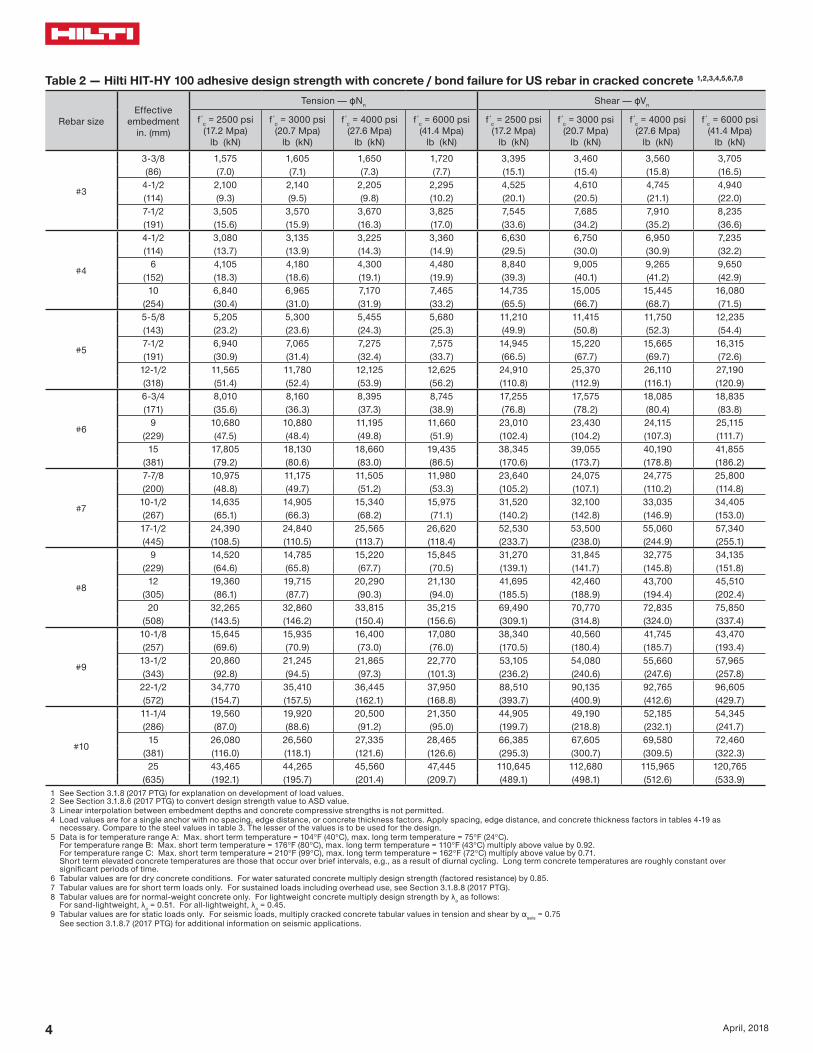
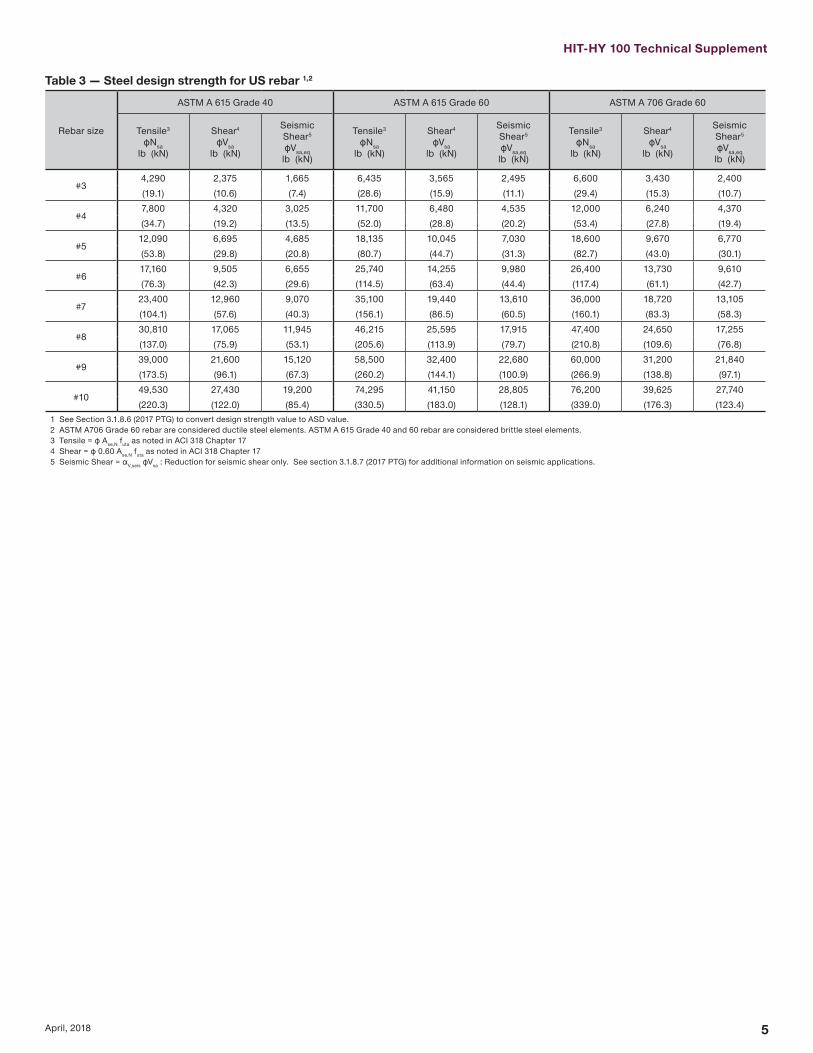
HIT-HY 100 Technical Supplement
5April 2018
Table 3 mdash Steel design strength for US rebar 12
Rebar size
ASTM A 615 Grade 40 ASTM A 615 Grade 60 ASTM A 706 Grade 60
Tensile3
ϕNsalb (kN)
Shear4
ϕVsalb (kN)
Seismic Shear5
ϕVsaeqlb (kN)
Tensile3
ϕNsalb (kN)
Shear4
ϕVsalb (kN)
Seismic Shear5
ϕVsaeqlb (kN)
Tensile3
ϕNsalb (kN)
Shear4
ϕVsalb (kN)
Seismic Shear5
ϕVsaeqlb (kN)
34290 2375 1665 6435 3565 2495 6600 3430 2400(191) (106) (74) (286) (159) (111) (294) (153) (107)
47800 4320 3025 11700 6480 4535 12000 6240 4370(347) (192) (135) (520) (288) (202) (534) (278) (194)
512090 6695 4685 18135 10045 7030 18600 9670 6770(538) (298) (208) (807) (447) (313) (827) (430) (301)
617160 9505 6655 25740 14255 9980 26400 13730 9610(763) (423) (296) (1145) (634) (444) (1174) (611) (427)
723400 12960 9070 35100 19440 13610 36000 18720 13105(1041) (576) (403) (1561) (865) (605) (1601) (833) (583)
830810 17065 11945 46215 25595 17915 47400 24650 17255(1370) (759) (531) (2056) (1139) (797) (2108) (1096) (768)
939000 21600 15120 58500 32400 22680 60000 31200 21840(1735) (961) (673) (2602) (1441) (1009) (2669) (1388) (971)
1049530 27430 19200 74295 41150 28805 76200 39625 27740(2203) (1220) (854) (3305) (1830) (1281) (3390) (1763) (1234)
1 See Section 3186 (2017 PTG) to convert design strength value to ASD value2 ASTM A706 Grade 60 rebar are considered ductile steel elements ASTM A 615 Grade 40 and 60 rebar are considered brittle steel elements3 Tensile = ϕ AseN futa as noted in ACI 318 Chapter 174 Shear = ϕ 060 AseN futa as noted in ACI 318 Chapter 175 Seismic Shear = αVseis ϕVsa Reduction for seismic shear only See section 3187 (2017 PTG) for additional information on seismic applications
6 April 2018
Table 4 mdash Load adjustment factors for 3 rebar in uncracked concrete 123
3Uncracked concrete
Spacing factor in tension
fAN
Edge distance factor in tension
fRN
Spacing factor in shear 4
fAV
Edge distance in shearConcrete thickness
factor in shear 5
fHV
Toward edge
fRV
To edge
fRV
Embedment hefin (mm)
3-38 4-12 7-12 3-38 4-12 7-12 3-38 4-12 7-12 3-38 4-12 7-12 3-38 4-12 7-12 3-38 4-12 7-12(86) (114) (191) (86) (114) (191) (86) (114) (191) (86) (114) (191) (86) (114) (191) (86) (114) (191)
Spac
ing
(s)
edg
e di
stan
ce (c
a) c
oncr
ete
thic
knes
s (h
) - i
n (m
m)
1-34 (44) na na na 032 023 013 na na na 010 008 005 021 016 009 na na na1-78 (48) 059 057 054 033 024 014 054 053 052 012 009 005 023 017 010 na na na
2 (51) 060 057 054 034 025 014 054 053 052 013 010 006 025 019 011 na na na3 (76) 065 061 057 042 031 018 056 055 054 023 017 010 042 031 018 na na na4 (102) 070 065 059 052 038 022 058 057 055 036 027 016 052 038 022 na na na
4-58 (117) 073 067 060 060 043 025 060 058 056 045 033 020 060 043 025 062 na na5 (127) 075 069 061 064 047 027 061 059 056 050 038 023 064 047 027 065 na na
5-34 (146) 078 071 063 074 054 031 062 060 057 062 046 028 074 054 031 070 063 na6 (152) 080 072 063 077 056 033 063 060 057 066 049 030 077 056 033 071 065 na7 (178) 085 076 066 090 066 038 065 062 059 083 062 037 090 066 038 077 070 na8 (203) 090 080 068 100 075 043 067 064 060 100 076 046 100 075 043 082 075 na
8-34 (222) 093 082 069 082 048 068 065 061 087 052 082 048 086 078 0669 (229) 094 083 070 084 049 069 066 061 091 055 084 049 087 079 06710 (254) 099 087 072 094 054 071 067 062 100 064 094 054 092 083 07011 (279) 100 091 074 100 060 073 069 064 074 100 060 096 087 07412 (305) 094 077 065 075 071 065 084 065 100 091 07714 (356) 100 081 076 079 074 067 100 076 099 08316 (406) 086 087 084 078 070 087 100 08918 (457) 090 098 088 081 072 098 09424 (610) 100 100 100 092 080 100 10030 (762) 100 08736 (914) 094
gt 48 (1219) 100
Table 5 mdash Load adjustment factors for 3 rebar in cracked concrete 123
3Cracked concrete
Spacing factor in tension
fAN
Edge distance factor in tension
fRN
Spacing factor in shear 4
fAV
Edge distance in shearConcrete thickness
factor in shear 5
fHV
Toward edge
fRV
To edge
fRV
Embedment hefin (mm)
3-38 4-12 7-12 3-38 4-12 7-12 3-38 4-12 7-12 3-38 4-12 7-12 3-38 4-12 7-12 3-38 4-12 7-12(86) (114) (191) (86) (114) (191) (86) (114) (191) (86) (114) (191) (86) (114) (191) (86) (114) (191)
Spac
ing
(s)
edg
e di
stan
ce (c
a) c
oncr
ete
thic
knes
s (h
) - i
n (m
m)
1-34 (44) na na na 054 049 043 na na na 010 007 004 020 015 009 na na na1-78 (48) 059 057 054 056 050 044 054 053 052 011 008 005 022 017 010 na na na
2 (51) 060 057 054 057 051 044 054 053 052 012 009 005 024 018 011 na na na3 (76) 065 061 057 070 060 049 056 055 054 022 017 010 045 034 020 na na na4 (102) 070 065 059 084 070 055 058 057 055 034 026 015 069 052 031 na na na
4-58 (117) 073 067 060 093 076 058 059 058 056 043 032 019 086 064 038 062 na na5 (127) 075 069 061 099 080 060 060 058 056 048 036 022 096 072 043 064 na na
5-34 (146) 078 071 063 100 088 064 062 060 057 059 044 027 100 088 053 069 062 na6 (152) 080 072 063 091 066 062 060 057 063 047 028 091 057 070 064 na7 (178) 085 076 066 100 072 064 062 058 080 060 036 100 072 076 069 na8 (203) 090 080 068 078 066 064 060 097 073 044 078 081 074 na
8-34 (222) 093 082 069 083 068 065 061 100 083 050 083 085 077 0659 (229) 094 083 070 085 068 065 061 087 052 085 086 078 06610 (254) 099 087 072 091 070 067 062 100 061 091 090 082 06911 (279) 100 091 074 098 073 069 063 071 098 095 086 07312 (305) 094 077 100 075 070 064 080 100 099 090 07614 (356) 100 081 100 079 074 067 100 100 097 08216 (406) 086 083 077 069 100 08818 (457) 090 087 080 072 09324 (610) 100 099 091 079 10030 (762) 100 100 08636 (914) 093
gt 48 (1219) 1001 Linear interpolation not permitted2 Shaded area with reduced edge distance is permitted provided the rebar has no installation torque3 When combining multiple load adjustment factors (eg for a four-anchor pattern in a corner with thin concrete member) the design can become very conservative To optimize the design
use Hilti PROFIS Anchor Design software or perform anchor calculation using design equations from ACI 318 Chapter 174 Spacing factor reduction in shear applicable when ca lt 3hef ƒAV is applicable when edge distance ca lt 3hef If ca ge 3hef then ƒAV = ƒAN 5 Concrete thickness reduction factor in shear ƒHV is applicable when edge distance ca lt 3hef If ca ge 3hef then ƒHV = 10
HIT-HY 100 Technical Supplement
7April 2018
Table 6 mdash Load adjustment factors for 4 rebar in uncracked concrete 123
4Uncracked concrete
Spacing factor in tension
fAN
Edge distance factor in tension
fRN
Spacing factor in shear 4
fAV
Edge distance in shearConcrete thickness
factor in shear 5
fHV
Toward edge
fRV
To edge
fRV
Embedment hefin (mm)
4-12 6 10 4-12 6 10 4-12 6 10 4-12 6 10 4-12 6 10 4-12 6 10 (114) (152) (254) (114) (152) (254) (114) (152) (254) (114) (152) (254) (114) (152) (254) (114) (152) (254)
Spac
ing
(s)
edg
e di
stan
ce (c
a) c
oncr
ete
thic
knes
s (h
) - i
n (m
m)
1-34 (44) na na na 027 020 012 na na na 007 005 003 014 010 006 na na na2-12 (64) 059 057 054 032 023 014 054 053 052 012 009 005 023 017 010 na na na
3 (76) 061 058 055 035 026 015 055 054 053 015 011 007 031 023 014 na na na4 (102) 065 061 057 041 030 018 056 055 054 023 018 011 041 030 018 na na na5 (127) 069 064 058 048 035 021 058 057 055 033 025 015 048 035 021 na na na
5-34 (146) 071 066 060 054 040 023 059 058 055 040 030 018 054 040 023 060 na na6 (152) 072 067 060 056 041 024 060 058 056 043 032 019 056 041 024 062 na na7 (178) 076 069 062 066 048 028 061 059 057 054 041 024 066 048 028 067 na na
7-14 (184) 077 070 062 068 050 029 062 059 057 057 043 026 068 050 029 068 062 na8 (203) 080 072 063 075 055 032 063 060 057 066 050 030 075 055 032 071 065 na9 (229) 083 075 065 085 062 036 064 062 058 079 059 036 085 062 036 076 069 na10 (254) 087 078 067 094 069 040 066 063 059 093 070 042 094 069 040 080 072 na
11-14 (286) 092 081 069 100 078 045 068 065 060 100 083 050 100 078 045 084 077 06512 (305) 094 083 070 083 048 069 066 061 092 055 083 048 087 079 06714 (356) 100 089 073 097 056 072 068 063 100 069 097 056 094 086 07216 (406) 094 077 100 065 075 071 065 085 100 065 100 092 07718 (457) 100 080 073 079 074 067 100 073 097 08220 (508) 083 081 082 076 069 081 100 08622 (559) 087 089 085 079 070 089 09124 (610) 090 097 088 081 072 097 09530 (762) 100 100 098 089 078 100 10036 (914) 100 097 084
gt 48 (1219) 100 095
Table 7 mdash Load adjustment factors for 4 rebar in cracked concrete 123
4Cracked concrete
Spacing factor in tension
fAN
Edge distance factor in tension
fRN
Spacing factor in shear 4
fAV
Edge distance in shearConcrete thickness
factor in shear 5
fHV
Toward edge
fRV
To edge
fRV
Embedment hefin (mm)
4-12 6 10 4-12 6 10 4-12 6 10 4-12 6 10 4-12 6 10 4-12 6 10 (114) (152) (254) (114) (152) (254) (114) (152) (254) (114) (152) (254) (114) (152) (254) (114) (152) (254)
Spac
ing
(s)
edg
e di
stan
ce (c
a) c
oncr
ete
thic
knes
s (h
) - i
n (m
m)
1-34 (44) na na na 049 045 041 na na na 006 005 003 013 010 006 na na na2-12 (64) 059 057 054 056 050 044 054 053 052 011 008 005 022 017 010 na na na
3 (76) 061 058 055 060 053 046 055 054 053 015 011 007 029 022 013 na na na4 (102) 065 061 057 070 060 049 056 055 054 022 017 010 045 034 020 na na na5 (127) 069 064 058 080 067 053 058 056 055 031 023 014 062 047 028 na na na
5-34 (146) 071 066 060 088 073 056 059 057 055 039 029 017 077 058 035 059 na na6 (152) 072 067 060 091 075 057 059 058 055 041 031 018 082 062 037 061 na na7 (178) 076 069 062 100 083 062 061 059 056 052 039 023 100 078 047 066 na na
7-14 (184) 077 070 062 085 063 061 059 057 055 041 025 082 049 067 061 na8 (203) 080 072 063 091 066 062 060 057 063 047 028 091 057 070 064 na9 (229) 083 075 065 100 070 064 061 058 075 057 034 100 068 074 068 na10 (254) 087 078 067 075 065 063 059 088 066 040 075 078 071 na
11-14 (286) 092 081 069 081 067 064 060 100 079 047 081 083 075 06412 (305) 094 083 070 085 068 065 061 087 052 085 086 078 06614 (356) 100 089 073 095 071 068 063 100 066 095 093 084 07116 (406) 094 077 100 075 070 064 080 100 099 090 07618 (457) 100 080 078 073 066 096 100 095 08120 (508) 083 081 075 068 100 100 08522 (559) 087 084 078 070 08924 (610) 090 087 080 072 09330 (762) 100 096 088 077 10036 (914) 100 096 082
gt 48 (1219) 100 0931 Linear interpolation not permitted2 Shaded area with reduced edge distance is permitted provided the rebar has no installation torque3 When combining multiple load adjustment factors (eg for a four-anchor pattern in a corner with thin concrete member) the design can become very conservative To optimize the design
use Hilti PROFIS Anchor Design software or perform anchor calculation using design equations from ACI 318 Chapter 174 Spacing factor reduction in shear applicable when ca lt 3hef ƒAV is applicable when edge distance ca lt 3hef If ca ge 3hef then ƒAV = ƒAN 5 Concrete thickness reduction factor in shear ƒHV is applicable when edge distance ca lt 3hef If ca ge 3hef then ƒHV = 10
8 April 2018
Table 8 mdash Load adjustment factors for 5 rebar in uncracked concrete 123
5Uncracked concrete
Spacing factor in tension
fAN
Edge distance factor in tension
fRN
Spacing factor in shear 4
fAV
Edge distance in shearConcrete thickness
factor in shear 5
fHV
Toward edge
fRV
To edge
fRV
Embedment hefin (mm)
5-58 7-12 12-12 5-58 7-12 12-12 5-58 7-12 12-12 5-58 7-12 12-12 5-58 7-12 12-12 5-58 7-12 12-12(143) (191) (318) (143) (191) (318) (143) (191) (318) (143) (191) (318) (143) (191) (318) (143) (191) (318)
Spac
ing
(s)
edg
e di
stan
ce (c
a) c
oncr
ete
thic
knes
s (h
) - i
n (m
m)
1-34 (44) na na na 025 019 011 na na na 005 004 002 010 007 004 na na na2-12 (64) 059 057 054 032 023 014 054 053 052 012 009 005 023 018 011 na na na
3 (76) 062 059 055 036 026 015 055 054 053 017 013 008 034 025 015 na na na4 (102) 065 061 057 041 030 018 056 055 054 024 018 011 041 030 018 na na na5 (127) 068 063 058 047 034 020 058 056 055 031 023 014 047 034 020 na na na
5-34 (146) 071 066 059 053 039 023 059 057 055 039 029 018 053 039 023 na na na6 (152) 071 066 060 054 039 023 059 058 055 040 030 018 054 039 023 060 na na7 (178) 074 068 061 060 044 026 060 058 056 048 036 022 060 044 026 064 na na
7-14 (184) 077 070 062 068 050 029 061 059 057 057 043 026 068 050 029 068 062 na8 (203) 080 072 063 075 055 032 063 061 058 067 050 030 075 055 032 071 065 na9 (229) 083 074 065 083 061 036 064 062 058 077 058 035 083 061 036 075 068 na10 (254) 086 077 066 090 066 039 065 063 059 088 066 040 090 066 039 078 071 na
11-14 (286) 091 081 069 100 077 045 068 065 061 100 083 050 100 077 045 085 077 06512 (305) 097 086 071 088 052 070 067 062 100 061 088 052 090 082 06914 (356) 100 090 074 099 058 073 069 064 073 099 058 096 087 07316 (406) 094 077 100 065 076 071 065 085 100 065 100 092 07718 (457) 099 079 071 078 073 067 099 071 096 08120 (508) 100 082 078 081 075 068 100 078 100 08522 (559) 085 084 083 077 070 084 08824 (610) 087 091 086 080 071 091 09230 (762) 090 097 088 082 073 097 09536 (914) 098 100 096 088 077 100 100
gt 48 (1219) 100 100 100 086
Table 9 mdash Load adjustment factors for 5 rebar in cracked concrete 123
5Cracked concrete
Spacing factor in tension
fAN
Edge distance factor in tension
fRN
Spacing factor in shear 4
fAV
Edge distance in shearConcrete thickness
factor in shear 5
fHV
Toward edge
fRV
To edge
fRV
Embedment hefin (mm)
5-58 7-12 12-12 5-58 7-12 12-12 5-58 7-12 12-12 5-58 7-12 12-12 5-58 7-12 12-12 5-58 7-12 12-12(143) (191) (318) (143) (191) (318) (143) (191) (318) (143) (191) (318) (143) (191) (318) (143) (191) (318)
Spac
ing
(s)
edg
e di
stan
ce (c
a) c
oncr
ete
thic
knes
s (h
) - i
n (m
m)
1-34 (44) na na na 046 043 040 na na na 005 003 002 009 007 004 na na na2-12 (64) 059 057 054 056 050 044 054 053 052 011 008 005 022 017 010 na na na
3 (76) 062 059 055 062 055 046 055 054 053 016 012 007 032 024 014 na na na4 (102) 065 061 057 070 060 049 056 055 054 022 017 010 045 034 020 na na na5 (127) 068 063 058 078 066 053 057 056 054 029 022 013 059 044 026 na na na
5-34 (146) 071 066 059 087 072 056 059 057 055 037 028 017 074 056 033 na na na6 (152) 071 066 060 088 073 056 059 057 055 038 029 017 076 057 034 059 na na7 (178) 074 068 061 096 078 059 060 058 056 045 034 020 090 068 041 063 na na
7-14 (184) 077 070 062 100 085 062 061 059 056 054 040 024 100 081 049 066 060 na8 (203) 080 072 063 091 066 062 060 057 063 047 028 091 057 070 064 na9 (229) 083 074 065 098 069 064 061 058 073 055 033 098 066 073 067 na10 (254) 086 077 066 100 073 065 062 059 083 062 037 100 073 077 070 na
11-14 (286) 091 081 069 081 067 064 060 100 079 047 081 083 075 06412 (305) 097 086 071 089 070 066 062 096 058 089 089 081 06814 (356) 100 090 074 097 072 068 063 100 069 097 094 085 07216 (406) 094 077 100 075 070 064 080 100 099 090 07618 (457) 099 079 077 072 066 093 100 094 08020 (508) 100 082 079 074 067 100 099 08322 (559) 085 082 076 069 100 08724 (610) 087 084 078 070 09030 (762) 090 087 080 072 09336 (914) 098 094 086 076 100
gt 48 (1219) 100 100 099 0851 Linear interpolation not permitted2 Shaded area with reduced edge distance is permitted provided the rebar has no installation torque3 When combining multiple load adjustment factors (eg for a four-anchor pattern in a corner with thin concrete member) the design can become very conservative To optimize the design
use Hilti PROFIS Anchor Design software or perform anchor calculation using design equations from ACI 318 Chapter 174 Spacing factor reduction in shear applicable when ca lt 3hef ƒAV is applicable when edge distance ca lt 3hef If ca ge 3hef then ƒAV = ƒAN 5 Concrete thickness reduction factor in shear ƒHV is applicable when edge distance ca lt 3hef If ca ge 3hef then ƒHV = 10
HIT-HY 100 Technical Supplement
9April 2018
Table 10 mdash Load adjustment factors for 6 rebar in uncracked concrete 123
6Uncracked concrete
Spacing factor in tension
fAN
Edge distance factor in tension
fRN
Spacing factor in shear 4
fAV
Edge distance in shearConcrete thickness
factor in shear 5
fHV
Toward edge
fRV
To edge
fRV
Embedment hefin (mm)
6-34 9 15 6-34 9 15 6-34 9 15 6-34 9 15 6-34 9 15 6-34 9 15 (171) (229) (381) (171) (229) (381) (171) (229) (381) (171) (229) (381) (171) (229) (381) (171) (229) (381)
Spac
ing
(s)
edg
e di
stan
ce (c
a) c
oncr
ete
thic
knes
s (h
) - i
n (m
m)
1-34 (44) na na na 024 018 010 na na na 004 003 002 007 006 003 na na na3-34 (95) 059 057 054 032 023 014 054 053 052 012 009 005 023 017 010 na na na
4 (102) 060 057 054 033 024 014 054 053 052 013 010 006 026 019 012 na na na5 (127) 062 059 056 037 027 016 055 054 053 018 013 008 036 027 016 na na na6 (152) 065 061 057 041 030 018 056 055 054 023 018 011 041 030 018 na na na8 (203) 070 065 059 051 037 022 058 057 055 036 027 016 051 037 022 na na na
8-12 (216) 071 066 059 053 039 023 059 057 055 040 030 018 053 039 023 060 na na10 (254) 075 069 061 063 046 027 061 059 056 051 038 023 063 046 027 065 na na
10-34 (273) 077 070 062 068 050 029 061 059 057 056 042 025 068 050 029 067 061 na12 (305) 080 072 063 075 055 032 063 060 057 066 050 030 075 055 032 071 065 na14 (356) 085 076 066 088 065 038 065 062 059 084 063 038 088 065 038 077 070 na16 (406) 090 080 068 100 074 043 067 064 060 100 077 046 100 074 043 082 075 na
16-34 (425) 091 081 069 077 045 068 065 060 082 049 077 045 084 076 06418 (457) 094 083 070 083 049 069 066 061 091 055 083 049 087 079 06720 (508) 099 087 072 092 054 071 067 062 100 064 092 054 092 084 07022 (559) 100 091 074 100 059 073 069 064 074 100 059 096 088 07424 (610) 094 077 065 075 071 065 085 065 100 092 07726 (660) 098 079 070 077 073 066 095 070 095 08028 (711) 100 081 076 080 074 067 100 076 099 08330 (762) 083 081 082 076 069 081 100 08636 (914) 090 097 088 081 072 097 095
gt 48 (1219) 100 100 100 092 080 100 100
Table 11 mdash Load adjustment factors for 6 rebar in cracked concrete 123
6Cracked concrete
Spacing factor in tension
fAN
Edge distance factor in tension
fRN
Spacing factor in shear 4
fAV
Edge distance in shearConcrete thickness
factor in shear 5
fHV
Toward edge
fRV
To edge
fRV
Embedment hefin (mm)
6-34 9 15 6-34 9 15 6-34 9 15 6-34 9 15 6-34 9 15 6-34 9 15 (171) (229) (381) (171) (229) (381) (171) (229) (381) (171) (229) (381) (171) (229) (381) (171) (229) (381)
Spac
ing
(s)
edg
e di
stan
ce (c
a) c
oncr
ete
thic
knes
s (h
) - i
n (m
m)
1-34 (44) na na na 044 042 039 na na na 003 003 002 007 005 003 na na na3-34 (95) 059 057 054 056 050 044 054 053 052 011 008 005 022 016 010 na na na
4 (102) 060 057 054 057 051 044 054 053 052 012 009 005 024 018 011 na na na5 (127) 062 059 056 063 056 047 055 054 053 017 012 007 034 025 015 na na na6 (152) 065 061 057 070 060 049 056 055 054 022 016 010 044 033 020 na na na8 (203) 070 065 059 084 070 055 058 057 055 034 025 015 068 051 030 na na na
8-12 (216) 071 066 059 088 072 056 059 057 055 037 028 017 075 055 033 059 na na10 (254) 075 069 061 099 080 060 060 058 056 048 035 021 095 071 042 064 na na
10-34 (273) 077 070 062 100 084 062 061 059 056 053 039 024 100 079 047 066 060 na12 (305) 080 072 063 091 066 062 060 057 063 046 028 091 056 070 063 na14 (356) 085 076 066 100 072 064 062 058 079 059 035 100 070 076 068 na16 (406) 090 080 068 078 066 063 059 097 071 043 078 081 073 na
16-34 (425) 091 081 069 081 067 064 060 100 077 046 081 083 075 06318 (457) 094 083 070 085 068 065 061 085 051 085 086 077 06520 (508) 099 087 072 091 070 067 062 100 060 091 090 082 06922 (559) 100 091 074 098 072 068 063 069 098 095 086 07224 (610) 094 077 100 074 070 064 079 100 099 089 07526 (660) 098 079 076 072 065 089 100 093 07828 (711) 100 081 079 073 067 099 097 08130 (762) 083 081 075 068 100 100 08436 (914) 090 087 080 071 092
gt 48 (1219) 100 099 090 078 1001 Linear interpolation not permitted2 Shaded area with reduced edge distance is permitted provided the rebar has no installation torque3 When combining multiple load adjustment factors (eg for a four-anchor pattern in a corner with thin concrete member) the design can become very conservative To optimize the design
use Hilti PROFIS Anchor Design software or perform anchor calculation using design equations from ACI 318 Chapter 174 Spacing factor reduction in shear applicable when ca lt 3hef ƒAV is applicable when edge distance ca lt 3hef If ca ge 3hef then ƒAV = ƒAN 5 Concrete thickness reduction factor in shear ƒHV is applicable when edge distance ca lt 3hef If ca ge 3hef then ƒHV = 10
10 April 2018
Table 12 mdash Load adjustment factors for 7 rebar in uncracked concrete 123
7Uncracked concrete
Spacing factor in tension
fAN
Edge distance factor in tension
fRN
Spacing factor in shear 4
fAV
Edge distance in shearConcrete thickness
factor in shear 5
fHV
Toward edge
fRV
To edge
fRV
Embedment hefin (mm)
7-78 10-12 17-12 7-78 10-12 17-12 7-78 10-12 17-12 7-78 10-12 17-12 7-78 10-12 17-12 7-78 10-12 17-12(200) (267) (445) (200) (267) (445) (200) (267) (445) (200) (267) (445) (200) (267) (445) (200) (267) (445)
Spac
ing
(s)
edg
e di
stan
ce (c
a) c
oncr
ete
thic
knes
s (h
) - i
n (m
m)
1-34 (44) na na na 023 017 010 na na na 003 002 001 005 004 002 na na na4-38 (111) 059 057 054 032 023 014 054 053 052 011 008 005 022 016 010 na na na
5 (127) 061 058 055 034 025 015 054 054 053 013 010 006 027 020 012 na na na6 (152) 063 060 056 037 028 016 055 054 053 017 013 008 035 026 016 na na na7 (178) 065 061 057 041 030 018 056 055 054 022 016 010 041 030 018 na na na8 (203) 067 063 058 045 033 019 057 056 054 027 020 012 045 033 019 na na na
9-78 (251) 071 066 059 053 039 023 059 057 055 037 028 017 053 039 023 059 na na10 (254) 071 066 060 054 040 023 059 057 055 038 028 017 054 040 023 059 na na12 (305) 075 069 061 065 048 028 060 059 056 049 037 022 065 048 028 065 na na
12-12 (318) 076 070 062 067 050 029 061 059 056 052 039 024 067 050 029 066 060 na14 (356) 080 072 063 075 055 033 062 060 057 062 046 028 075 055 033 070 063 na16 (406) 084 075 065 086 063 037 064 061 058 076 057 034 086 063 037 075 068 na18 (457) 088 079 067 097 071 042 066 063 059 091 068 041 097 071 042 079 072 na
19-12 (495) 091 081 069 100 077 045 067 064 060 100 076 046 100 077 045 082 075 06320 (508) 092 082 069 079 046 067 064 060 079 048 079 046 083 076 06422 (559) 097 085 071 087 051 069 066 061 092 055 087 051 087 079 06724 (610) 100 088 073 095 056 071 067 062 100 063 095 056 091 083 07026 (660) 091 075 100 060 073 069 063 071 100 060 095 086 07328 (711) 094 077 065 074 070 064 079 065 099 089 07530 (762) 098 079 070 076 071 065 087 070 100 093 07836 (914) 100 084 084 081 076 068 100 084 100 086
gt 48 (1219) 096 100 092 084 074 100 099
Table 13 mdash Load adjustment factors for 7 rebar in cracked concrete 123
7Cracked concrete
Spacing factor in tension
fAN
Edge distance factor in tension
fRN
Spacing factor in shear 4
fAV
Edge distance in shearConcrete thickness
factor in shear 5
fHV
Toward edge
fRV
To edge
fRV
Embedment hefin (mm)
7-78 10-12 17-12 7-78 10-12 17-12 7-78 10-12 17-12 7-78 10-12 17-12 7-78 10-12 17-12 7-78 10-12 17-12(200) (267) (445) (200) (267) (445) (200) (267) (445) (200) (267) (445) (200) (267) (445) (200) (267) (445)
Spac
ing
(s)
edg
e di
stan
ce (c
a) c
oncr
ete
thic
knes
s (h
) - i
n (m
m)
1-34 (44) na na na 043 041 038 na na na 003 002 001 006 005 003 na na na4-38 (111) 059 057 054 056 050 044 054 053 052 012 009 005 024 018 011 na na na
5 (127) 061 058 055 059 052 045 055 054 053 015 011 007 029 022 013 na na na6 (152) 063 060 056 064 056 047 056 055 053 019 014 009 038 029 017 na na na7 (178) 065 061 057 070 060 049 056 055 054 024 018 011 048 036 022 na na na8 (203) 067 063 058 076 064 052 057 056 054 029 022 013 059 044 026 na na na
9-78 (251) 071 066 059 087 072 056 059 058 055 040 030 018 081 060 036 060 na na10 (254) 071 066 060 088 073 056 059 058 055 041 031 018 082 062 037 061 na na12 (305) 075 069 061 100 082 061 061 059 056 054 041 024 100 081 049 066 na na
12-12 (318) 076 070 062 084 062 062 060 057 057 043 026 100 084 052 068 062 na14 (356) 080 072 063 091 066 063 061 058 068 051 031 091 061 072 065 na16 (406) 084 075 065 100 071 065 062 059 083 062 037 100 071 077 070 na18 (457) 088 079 067 076 067 064 060 099 074 045 076 081 074 na
19-12 (495) 091 081 069 080 068 065 061 100 084 050 080 085 077 06520 (508) 092 082 069 082 068 065 061 087 052 082 086 078 06622 (559) 097 085 071 087 070 067 062 100 060 087 090 082 06924 (610) 100 088 073 093 072 068 063 069 093 094 085 07226 (660) 091 075 099 074 070 064 078 099 098 089 07528 (711) 094 077 100 076 071 065 087 100 100 092 07830 (762) 098 079 078 073 066 096 096 08136 (914) 100 084 083 077 069 100 100 088
gt 48 (1219) 096 094 086 076 1001 Linear interpolation not permitted2 Shaded area with reduced edge distance is permitted provided the rebar has no installation torque3 When combining multiple load adjustment factors (eg for a four-anchor pattern in a corner with thin concrete member) the design can become very conservative To optimize the design
use Hilti PROFIS Anchor Design software or perform anchor calculation using design equations from ACI 318 Chapter 174 Spacing factor reduction in shear applicable when ca lt 3hef ƒAV is applicable when edge distance ca lt 3hef If ca ge 3hef then ƒAV = ƒAN 5 Concrete thickness reduction factor in shear ƒHV is applicable when edge distance ca lt 3hef If ca ge 3hef then ƒHV = 10
HIT-HY 100 Technical Supplement
11April 2018
Table 14 mdash Load adjustment factors for 8 rebar in uncracked concrete 123
8Uncracked concrete
Spacing factor in tension
fAN
Edge distance factor in tension
fRN
Spacing factor in shear 4
fAV
Edge distance in shearConcrete thickness
factor in shear 5
fHV
Toward edge
fRV
To edge
fRV
Embedment hefin (mm)
9 12 20 9 12 20 9 12 20 9 12 20 9 12 20 9 12 20 (229) (305) (508) (229) (305) (508) (229) (305) (508) (229) (305) (508) (229) (305) (508) (229) (305) (508)
Spac
ing
(s)
edg
e di
stan
ce (c
a) c
oncr
ete
thic
knes
s (h
) - i
n (m
m)
1-34 (44) na na na 023 017 010 na na na 002 002 001 005 003 002 na na na5 (127) 059 057 054 032 023 014 054 053 052 011 008 005 022 015 009 na na na6 (152) 061 058 055 035 026 015 055 054 053 014 010 006 029 020 012 na na na7 (178) 063 060 056 038 028 016 055 054 053 018 013 008 036 025 015 na na na8 (203) 065 061 057 041 030 018 056 055 053 022 015 009 041 030 018 na na na9 (229) 067 063 058 045 033 019 057 055 054 026 018 011 045 033 019 na na na10 (254) 069 064 058 048 036 021 058 056 054 031 022 013 048 036 021 na na na
11-14 (286) 071 066 059 053 039 023 059 057 055 037 026 016 053 039 023 058 na na12 (305) 072 067 060 057 042 024 059 057 055 040 028 017 057 042 024 060 na na14 (356) 076 069 062 066 049 029 061 058 056 051 036 022 066 049 029 065 na na
14-14 (362) 076 070 062 067 050 029 061 059 056 052 037 022 067 050 029 066 059 na16 (406) 080 072 063 076 056 033 062 060 057 062 044 026 076 056 033 070 062 na18 (457) 083 075 065 085 063 037 064 061 058 074 052 031 085 063 037 074 066 na20 (508) 087 078 067 095 070 041 065 062 059 087 061 037 095 070 041 078 069 na22 (559) 091 081 068 100 076 045 067 063 059 100 071 042 100 076 045 082 073 na
22-14 (565) 091 081 069 077 045 067 063 060 072 043 077 045 082 073 06224 (610) 094 083 070 083 049 068 064 060 081 048 083 049 085 076 06426 (660) 098 086 072 090 053 070 066 061 091 054 090 053 089 079 06728 (711) 100 089 073 097 057 071 067 062 100 061 097 057 092 082 06930 (762) 092 075 100 061 073 068 063 068 100 061 095 085 07236 (914) 100 080 073 077 072 065 089 073 100 093 078
gt 48 (1219) 090 098 086 079 071 100 098 100 091
Table 15 mdash Load adjustment factors for 8 rebar in cracked concrete 123
8Cracked concrete
Spacing factor in tension
fAN
Edge distance factor in tension
fRN
Spacing factor in shear 4
fAV
Edge distance in shearConcrete thickness
factor in shear 5
fHV
Toward edge
fRV
To edge
fRV
Embedment hefin (mm)
9 12 20 9 12 20 9 12 20 9 12 20 9 12 20 9 12 20 (229) (305) (508) (229) (305) (508) (229) (305) (508) (229) (305) (508) (229) (305) (508) (229) (305) (508)
Spac
ing
(s)
edg
e di
stan
ce (c
a) c
oncr
ete
thic
knes
s (h
) - i
n (m
m)
1-34 (44) na na na 042 040 038 na na na 002 002 001 005 003 002 na na na5 (127) 059 057 054 056 050 044 054 053 052 011 008 005 022 017 010 na na na6 (152) 061 058 055 060 053 046 055 054 053 015 011 007 029 022 013 na na na7 (178) 063 060 056 065 057 047 055 054 053 018 014 008 037 028 017 na na na8 (203) 065 061 057 070 060 049 056 055 054 023 017 010 045 034 020 na na na9 (229) 067 063 058 075 064 051 057 056 054 027 020 012 054 040 024 na na na10 (254) 069 064 058 080 067 053 058 056 055 031 024 014 063 047 028 na na na
11-14 (286) 071 066 059 087 072 056 059 057 055 038 028 017 075 056 034 059 na na12 (305) 072 067 060 091 075 057 059 058 055 041 031 019 083 062 037 061 na na14 (356) 076 069 062 100 083 062 061 059 056 052 039 023 100 078 047 066 na na
14-14 (362) 076 070 062 084 062 061 059 056 054 040 024 080 048 066 060 na16 (406) 080 072 063 091 066 062 060 057 064 048 029 091 057 070 064 na18 (457) 083 075 065 100 070 064 061 058 076 057 034 100 068 075 068 na20 (508) 087 078 067 075 065 063 059 089 067 040 075 079 071 na22 (559) 091 081 068 080 067 064 060 100 077 046 080 082 075 na
22-14 (565) 091 081 069 080 067 064 060 078 047 080 083 075 06324 (610) 094 083 070 085 069 065 061 088 053 085 086 078 06626 (660) 098 086 072 090 070 067 062 099 059 090 090 081 06928 (711) 100 089 073 095 072 068 063 100 066 095 093 084 07130 (762) 092 075 100 073 069 064 074 100 096 087 07436 (914) 100 080 078 073 066 097 100 096 081
gt 48 (1219) 090 087 081 072 100 100 0931 Linear interpolation not permitted2 Shaded area with reduced edge distance is permitted provided the rebar has no installation torque3 When combining multiple load adjustment factors (eg for a four-anchor pattern in a corner with thin concrete member) the design can become very conservative To optimize the design
use Hilti PROFIS Anchor Design software or perform anchor calculation using design equations from ACI 318 Chapter 174 Spacing factor reduction in shear applicable when ca lt 3hef ƒAV is applicable when edge distance ca lt 3hef If ca ge 3hef then ƒAV = ƒAN 5 Concrete thickness reduction factor in shear ƒHV is applicable when edge distance ca lt 3hef If ca ge 3hef then ƒHV = 10
12 April 2018
Table 16 mdash Load adjustment factors for 9 rebar in uncracked concrete 123
9Uncracked concrete
Spacing factor in tension
fAN
Edge distance factor in tension
fRN
Spacing factor in shear 4
fAV
Edge distance in shearConcrete thickness
factor in shear 5
fHV
Toward edge
fRV
To edge
fRV
Embedment hefin (mm)
10-18 13-12 22-12 10-18 13-12 22-12 10-18 13-12 22-12 10-18 13-12 22-12 10-18 13-12 22-12 10-18 13-12 22-12(257) (343) (572) (257) (343) (572) (257) (343) (572) (257) (343) (572) (257) (343) (572) (257) (343) (572)
Spac
ing
(s)
edg
e di
stan
ce (c
a) c
oncr
ete
thic
knes
s (h
) - i
n (m
m)
1-34 (44) na na na 022 016 010 na na na 002 001 001 004 003 002 na na na5-58 (143) 059 057 054 032 024 014 054 053 052 011 008 005 022 015 009 na na na
6 (152) 060 057 054 033 024 014 054 053 052 012 008 005 024 017 010 na na na7 (178) 062 059 055 036 026 015 055 054 053 015 011 006 030 021 013 na na na8 (203) 063 060 056 039 029 017 055 054 053 018 013 008 037 026 016 na na na9 (229) 065 061 057 042 031 018 056 055 053 022 016 009 042 031 018 na na na10 (254) 066 062 057 045 033 019 057 055 054 026 018 011 045 033 019 na na na12 (305) 070 065 059 052 038 022 058 056 055 034 024 014 052 038 022 na na na
12-78 (327) 071 066 060 056 041 024 059 057 055 038 027 016 056 041 024 059 na na14 (356) 073 067 060 061 045 026 059 057 055 043 030 018 061 045 026 061 na na16 (406) 076 070 062 069 051 030 061 059 056 052 037 022 069 051 030 066 na na
16-14 (413) 077 070 062 070 052 030 061 059 056 053 038 023 070 052 030 066 059 na18 (457) 080 072 063 078 057 033 062 060 057 062 044 026 078 057 033 070 062 na20 (508) 083 075 065 087 064 037 063 061 058 073 051 031 087 064 037 073 065 na22 (559) 086 077 066 095 070 041 065 062 058 084 059 036 095 070 041 077 069 na24 (610) 090 080 068 100 076 045 066 063 059 096 067 040 100 076 045 080 072 na
25-14 (641) 092 081 069 080 047 067 063 060 100 073 044 080 047 083 073 06226 (660) 093 082 069 083 048 068 064 060 076 046 083 048 084 075 06328 (711) 096 085 071 089 052 069 065 061 085 051 089 052 087 077 06530 (762) 099 087 072 095 056 070 066 061 094 057 095 056 090 080 06836 (914) 100 094 077 100 067 074 069 064 100 074 100 067 099 088 074
gt 48 (1219) 100 086 100 089 082 076 068 100 089 100 100 085
Table 17 mdash Load adjustment factors for 9 rebar in cracked concrete 123
9Cracked concrete
Spacing factor in tension
fAN
Edge distance factor in tension
fRN
Spacing factor in shear 4
fAV
Edge distance in shearConcrete thickness
factor in shear 5
fHV
Toward edge
fRV
To edge
fRV
Embedment hefin (mm)
10-18 13-12 22-12 10-18 13-12 22-12 10-18 13-12 22-12 10-18 13-12 22-12 10-18 13-12 22-12 10-18 13-12 22-12(257) (343) (572) (257) (343) (572) (257) (343) (572) (257) (343) (572) (257) (343) (572) (257) (343) (572)
Spac
ing
(s)
edg
e di
stan
ce (c
a) c
oncr
ete
thic
knes
s (h
) - i
n (m
m)
1-34 (44) na na na 041 039 038 na na na 002 001 001 004 003 002 na na na5-58 (143) 059 057 054 056 050 044 054 053 052 011 008 005 022 016 009 na na na
6 (152) 060 057 054 057 051 044 054 053 052 012 009 005 024 017 010 na na na7 (178) 062 059 055 061 054 046 055 054 053 015 011 007 030 022 013 na na na8 (203) 063 060 056 065 057 048 055 054 053 019 013 008 037 027 016 na na na9 (229) 065 061 057 070 060 049 056 055 053 022 016 010 044 032 019 na na na10 (254) 066 062 057 074 063 051 057 055 054 026 019 011 052 037 022 na na na12 (305) 070 065 059 084 070 055 058 057 055 034 025 015 068 049 029 na na na
12-78 (327) 071 066 060 088 073 056 059 057 055 038 027 016 076 054 033 059 na na14 (356) 073 067 060 094 077 058 060 058 055 043 031 019 086 062 037 062 na na16 (406) 076 070 062 100 084 062 061 059 056 053 038 023 100 075 045 066 na na
16-14 (413) 077 070 062 085 063 061 059 056 054 039 023 077 046 066 059 na18 (457) 080 072 063 091 066 062 060 057 063 045 027 090 054 070 063 na20 (508) 083 075 065 099 070 064 061 058 073 053 032 099 063 074 066 na22 (559) 086 077 066 100 074 065 062 059 085 061 036 100 073 077 069 na24 (610) 090 080 068 078 066 063 059 097 069 042 078 081 072 na
25-14 (641) 092 081 069 081 067 064 060 100 075 045 081 083 074 06326 (660) 093 082 069 082 068 064 060 078 047 082 084 075 06328 (711) 096 085 071 087 069 065 061 087 052 087 087 078 06630 (762) 099 087 072 091 070 066 062 097 058 091 090 081 06836 (914) 100 094 077 100 074 070 064 100 076 100 099 088 075
gt 48 (1219) 100 086 083 076 069 100 100 100 0861 Linear interpolation not permitted2 Shaded area with reduced edge distance is permitted provided the rebar has no installation torque3 When combining multiple load adjustment factors (eg for a four-anchor pattern in a corner with thin concrete member) the design can become very conservative To optimize the design
use Hilti PROFIS Anchor Design software or perform anchor calculation using design equations from ACI 318 Chapter 174 Spacing factor reduction in shear applicable when ca lt 3hef ƒAV is applicable when edge distance ca lt 3hef If ca ge 3hef then ƒAV = ƒAN 5 Concrete thickness reduction factor in shear ƒHV is applicable when edge distance ca lt 3hef If ca ge 3hef then ƒHV = 10
HIT-HY 100 Technical Supplement
13April 2018
Table 18 mdash Load adjustment factors for 10 rebar in uncracked concrete 123
10Uncracked concrete
Spacing factor in tension
fAN
Edge distance factor in tension
fRN
Spacing factor in shear 4
fAV
Edge distance in shearConcrete thickness
factor in shear 5
fHV
Toward edge
fRV
To edge
fRV
Embedment hefin (mm)
11-14 15 25 11-14 15 25 11-14 15 25 11-14 15 25 11-14 15 25 11-14 15 25 (286) (381) (635) (286) (381) (635) (286) (381) (635) (286) (381) (635) (286) (381) (635) (286) (381) (635)
Spac
ing
(s)
edg
e di
stan
ce (c
a) c
oncr
ete
thic
knes
s (h
) - i
n (m
m) 1-34 (44) na na na 022 016 009 na na na 002 001 001 003 002 001 na na na
6-14 (159) 059 057 054 033 024 014 054 053 052 011 008 005 022 016 010 na na na7 (178) 060 058 055 035 025 015 054 053 052 013 010 006 026 019 012 na na na8 (203) 062 059 055 037 027 016 055 054 053 016 012 007 031 023 014 na na na9 (229) 063 060 056 040 030 017 055 054 053 019 014 008 038 028 017 na na na10 (254) 065 061 057 043 032 019 056 055 054 022 016 010 043 032 019 na na na11 (279) 066 062 057 046 034 020 057 055 054 025 019 011 046 034 020 na na na12 (305) 068 063 058 049 036 021 057 056 054 029 022 013 049 036 021 na na na14 (356) 071 066 059 057 042 024 059 057 055 036 027 016 057 042 024 na na na
14-14 (362) 071 066 060 058 043 025 059 057 055 037 028 017 058 043 025 059 na na16 (406) 074 068 061 065 048 028 060 058 056 045 033 020 065 048 028 062 na na17 (432) 075 069 061 069 051 030 060 058 056 049 036 022 069 051 030 064 na na18 (457) 077 070 062 073 054 031 061 059 056 053 040 024 073 054 031 066 060 na20 (508) 080 072 063 081 060 035 062 060 057 062 046 028 081 060 035 070 063 na22 (559) 083 074 065 089 066 038 063 061 058 072 054 032 089 066 038 073 066 na24 (610) 086 077 066 098 072 042 065 062 059 082 061 037 098 072 042 076 069 na26 (660) 089 079 067 100 078 045 066 063 059 092 069 041 100 078 045 079 072 na28 (711) 091 081 069 084 049 067 064 060 100 077 046 084 049 082 075 06330 (762) 094 083 070 090 052 068 065 061 085 051 090 052 085 077 06536 (914) 100 090 074 100 063 072 068 063 100 067 100 063 094 085 072
gt 48 (1219) 100 082 084 079 074 067 100 084 100 098 083
Table 19 mdash Load adjustment factors for 10 rebar in cracked concrete 123
10Cracked concrete
Spacing factor in tension
fAN
Edge distance factor in tension
fRN
Spacing factor in shear 4
fAV
Edge distance in shearConcrete thickness
factor in shear 5
fHV
Toward edge
fRV
To edge
fRV
Embedment hefin (mm)
11-14 15 25 11-14 15 25 11-14 15 25 11-14 15 25 11-14 15 25 11-14 15 25 (286) (381) (635) (286) (381) (635) (286) (381) (635) (286) (381) (635) (286) (381) (635) (286) (381) (635)
Spac
ing
(s)
edg
e di
stan
ce (c
a) c
oncr
ete
thic
knes
s (h
) - i
n (m
m) 1-34 (44) na na na 040 039 037 na na na 002 001 001 003 002 001 na na na
6-14 (159) 059 057 054 056 050 044 054 053 052 011 007 004 022 015 009 na na na7 (178) 060 058 055 058 052 045 054 053 052 013 009 005 026 018 011 na na na8 (203) 062 059 055 062 055 046 055 054 053 016 011 006 032 022 013 na na na9 (229) 063 060 056 066 057 048 055 054 053 019 013 008 038 026 015 na na na10 (254) 065 061 057 070 060 049 056 055 053 022 015 009 044 030 018 na na na11 (279) 066 062 057 074 063 051 057 055 054 026 017 010 051 035 021 na na na12 (305) 068 063 058 078 066 053 057 056 054 029 020 012 058 040 024 na na na14 (356) 071 066 059 087 072 056 059 057 055 037 025 015 073 050 030 na na na
14-14 (362) 071 066 060 088 073 056 059 057 055 038 026 015 075 051 031 059 na na16 (406) 074 068 061 096 078 059 060 058 055 045 031 018 090 061 037 063 na na17 (432) 075 069 061 100 081 061 060 058 056 049 033 020 098 067 040 064 na na18 (457) 077 070 062 085 062 061 059 056 054 036 022 100 073 044 066 058 na20 (508) 080 072 063 091 066 062 059 057 063 043 026 085 051 070 061 na22 (559) 083 074 065 098 069 063 060 057 072 049 030 098 059 073 064 na24 (610) 086 077 066 100 073 065 061 058 082 056 034 100 067 077 067 na26 (660) 089 079 067 077 066 062 059 093 063 038 076 080 070 na28 (711) 091 081 069 081 067 063 059 100 071 042 081 083 073 06130 (762) 094 083 070 085 068 064 060 078 047 085 086 075 06436 (914) 100 090 074 097 072 067 062 100 062 097 094 082 070
gt 48 (1219) 100 082 100 079 073 066 095 100 100 095 0801 Linear interpolation not permitted2 Shaded area with reduced edge distance is permitted provided the rebar has no installation torque3 When combining multiple load adjustment factors (eg for a four-anchor pattern in a corner with thin concrete member) the design can become very conservative To optimize the design
use Hilti PROFIS Anchor Design software or perform anchor calculation using design equations from ACI 318 Chapter 174 Spacing factor reduction in shear applicable when ca lt 3hef ƒAV is applicable when edge distance ca lt 3hef If ca ge 3hef then ƒAV = ƒAN 5 Concrete thickness reduction factor in shear ƒHV is applicable when edge distance ca lt 3hef If ca ge 3hef then ƒHV = 10
14 April 2018
Hilti HIT-HY 100 adhesive with Hilti HAS threaded rod
HIT-VHAS
Hilti HAS HIT-V threaded rod installation conditions
Perm
issi
ble
Bas
e M
ater
ials
Uncracked concrete
DryConcrete
Perm
issi
ble
Dril
ling
Met
hod
Hammer Drilling with Carbide Tipped
Drill Bit
Cracked concrete
Water Saturated Concrete
Hollow Drill Bit
Hilti HASHIT-V threaded rod installation specifications
Nominal Rod
Diameter
Drill Bit Diameter
Embedment Depth Range
Maximum Installation
Torque
Minimum Base Material
Thickness
din (mm)
d0in
hefin (mm)
Tmaxft-lb (Nm)
hminin (mm)
38716
2-38 ndash 7-12 15hef + 1-14 (hef + 30)
(95) (60 ndash 191) (20)12
916 2-34 ndash 10 30
(127) (70 ndash 254) (41)58
343-18 ndash 12-12 60
hef + 2d0
(159) (79 ndash 318) (81)34
783-12 ndash 15 100
(191) (89 ndash 381) (136)78
13-12 ndash 17-12 125
(222) (89 ndash 445) (169)1
1-184 ndash 20 150
(254) (102 ndash 508) (203)1-14
1-385 ndash 25 200
(318) (127 ndash 635) (271)
min
max
df HASHIT-V 38 12 58 34 78 1 1-14
df1 12 58 1316 1516 1-18 1-14 1-12
df2 716 916 1116 1316 1516 1-18 1-38 Use two washers
HIT-HY 100 Technical Supplement
15April 2018
Table 20 mdash Hilti HIT-HY 100 adhesive design strength with concrete bond failure for threaded rod in uncracked concrete 12345678
Nominal anchor
diameterin
Effective embedment
in (mm)
Tension mdash ϕNn Shear mdash ϕVn
f´c = 2500 psi(172 Mpa)
lb (kN)
f´c = 3000 psi(207 Mpa)
lb (kN)
f´c = 4000 psi(276 Mpa)
lb (kN)
f´c = 6000 psi(414 Mpa)
lb (kN)
f´c = 2500 psi(172 Mpa)
lb (kN)
f´c = 3000 psi(207 Mpa)
lb (kN)
f´c = 4000 psi(276 Mpa)
lb (kN)
f´c = 6000 psi(414 Mpa)
lb (kN)
38
2-38 2710 2760 2840 2960 2920 2970 3060 3185(60) (121) (123) (126) (132) (130) (132) (136) (142)
3-38 3850 3920 4035 4205 8295 8445 8695 9055(86) (171) (174) (179) (187) (369) (376) (387) (403)
4-12 5135 5230 5380 5605 11060 11260 11590 12070(114) (228) (233) (239) (249) (492) (501) (516) (537)7-12 8555 8715 8970 9340 18430 18770 19320 20120(191) (381) (388) (399) (415) (820) (835) (859) (895)
12
2-34 3555 3895 4385 4565 7660 8395 9445 9835(70) (158) (173) (195) (203) (341) (373) (420) (437)
4-12 6845 6970 7175 7470 14745 15015 15455 16095(114) (304) (310) (319) (332) (656) (668) (687) (716)
6 9130 9295 9565 9965 19660 20020 20605 21460(152) (406) (413) (425) (443) (875) (891) (917) (955)10 15215 15495 15945 16605 32765 33370 34345 35765
(254) (677) (689) (709) (739) (1457) (1484) (1528) (1591)
58
3-18 4310 4720 5450 6485 9280 10165 11740 13970(79) (192) (210) (242) (288) (413) (452) (522) (621)
5-58 10405 10895 11210 11675 22415 23465 24150 25145(143) (463) (485) (499) (519) (997) (1044) (1074) (1119)7-12 14260 14525 14950 15565 30720 31285 32195 33530(191) (634) (646) (665) (692) (1366) (1392) (1432) (1491)
12-12 23770 24210 24915 25945 51200 52140 53660 55880(318) (1057) (1077) (1108) (1154) (2277) (2319) (2387) (2486)
34
3-12 5105 5595 6460 7910 11000 12050 13915 17040(89) (227) (249) (287) (352) (489) (536) (619) (758)
6-34 13680 14985 16145 16815 29460 32275 34775 36210(171) (609) (667) (718) (748) (1310) (1436) (1547) (1611)
9 20540 20915 21525 22415 44235 45050 46365 48280(229) (914) (930) (957) (997) (1968) (2004) (2062) (2148)
15 34230 34860 35875 37360 73725 75080 77275 80470(381) (1523) (1551) (1596) (1662) (3279) (3340) (3437) (3579)
78
3-12 5105 5595 6460 7910 11000 12050 13915 17040(89) (227) (249) (287) (352) (489) (536) (619) (758)7-78 17235 18885 20500 21350 37125 40670 44155 45980(200) (767) (840) (912) (950) (1651) (1809) (1964) (2045)
10-12 26080 26560 27335 28465 56170 57200 58870 61305(267) (1160) (1181) (1216) (1266) (2499) (2544) (2619) (2727)17-12 43465 44265 45555 47440 93615 95335 98120 102180(445) (1933) (1969) (2026) (2110) (4164) (4241) (4365) (4545)
1
4 6240 6835 7895 9665 13440 14725 17000 20820(102) (278) (304) (351) (430) (598) (655) (756) (926)
9 21060 23070 24465 25475 45360 49690 52690 54870(229) (937) (1026) (1088) (1133) (2018) (2210) (2344) (2441)
12 31120 31695 32620 33970 67030 68260 70255 73160(305) (1384) (1410) (1451) (1511) (2982) (3036) (3125) (3254)
20 51870 52820 54365 56615 111715 113770 117090 121935(508) (2307) (2350) (2418) (2518) (4969) (5061) (5208) (5424)
1-14
5 8720 9555 11030 12140 18785 20575 23760 29100(127) (388) (425) (491) (540) (836) (915) (1057) (1294)11-14 25025 25490 26230 27315 63395 64880 66770 69535(286) (1113) (1134) (1167) (1215) (2820) (2886) (2970) (3093)
15 33370 33985 34975 36425 84940 86505 89030 92710(381) (1484) (1512) (1556) (1620) (3778) (3848) (3960) (4124)25 55615 56640 58290 60705 141570 144175 148380 154520
(635) (2474) (2519) (2593) (2700) (6297) (6413) (6600) (6873)1 See Section 318 (2017 PTG) for explanation on development of load values2 See Section 3186 (2017 PTG) to convert design strength value to ASD value3 Linear interpolation between embedment depths and concrete compressive strengths is not permitted4 Load values are for a single anchor with no spacing edge distance or concrete thickness factors Apply spacing edge distance and concrete thickness factors in tables 23-35 as
necessary Compare to the steel values in table 22 The lesser of the values is to be used for the design5 Data is for temperature range A Max short term temperature = 130degF (55degC) max long term temperature = 110degF (43degC) For temperature range B Max short term temperature = 176degF (80degC) max long term temperature = 110degF (43degC) multiply above value by 092 For temperature range C Max short term temperature = 210degF (99degC) max long term temperature = 162degF (72degC) multiply above value by 071 Short term elevated concrete temperatures are those that occur over brief intervals eg as a result of diurnal cycling Long term concrete temperatures are roughly constant over significant periods of time6 Tabular values are for dry concrete conditions For water saturated concrete multiply design strength (factored resistance) by 0857 Tabular values are for short term loads only For sustained loads including overhead use see Section 3188 (2017 PTG)8 Tabular values are for normal-weight concrete only For lightweight concrete multiply design strength by λa as follows For sand-lightweight λa = 051 For all-lightweight λa = 045
16 April 2018
Table 21 mdash Hilti HIT-HY 100 adhesive design strength with concrete bond failure for threaded rod in cracked concrete 123456789
Nominal anchor
diameterin
Effective embedment
in (mm)
Tension mdash ϕNn Shear mdash ϕVn
f´c = 2500 psi(172 Mpa)
lb (kN)
f´c = 3000 psi(207 Mpa)
lb (kN)
f´c = 4000 psi(276 Mpa)
lb (kN)
f´c = 6000 psi(414 Mpa)
lb (kN)
f´c = 2500 psi(172 Mpa)
lb (kN)
f´c = 3000 psi(207 Mpa)
lb (kN)
f´c = 4000 psi(276 Mpa)
lb (kN)
f´c = 6000 psi(414 Mpa)
lb (kN)
38
2-38 1120 1140 1170 1220 1205 1225 1260 1315(60) (50) (51) (52) (54) (54) (54) (56) (58)
3-38 1590 1620 1665 1735 3425 3485 3590 3735(86) (71) (72) (74) (77) (152) (155) (160) (166)
4-12 2120 2160 2220 2315 4565 4650 4785 4980(114) (94) (96) (99) (103) (203) (207) (213) (222)7-12 3530 3595 3700 3855 7610 7750 7975 8305(191) (157) (160) (165) (171) (339) (345) (355) (369)
12
2-34 1880 1915 1970 2055 4050 4125 4245 4425(70) (84) (85) (88) (91) (180) (183) (189) (197)
4-12 3080 3135 3225 3360 6630 6750 6950 7235(114) (137) (139) (143) (149) (295) (300) (309) (322)
6 4105 4180 4300 4480 8840 9005 9265 9650(152) (183) (186) (191) (199) (393) (401) (412) (429)10 6840 6965 7170 7465 14735 15005 15445 16080
(254) (304) (310) (319) (332) (655) (667) (687) (715)
58
3-18 2890 2945 3030 3155 6230 6345 6530 6800(79) (129) (131) (135) (140) (277) (282) (290) (302)
5-58 5205 5300 5455 5680 11210 11415 11750 12235(143) (232) (236) (243) (253) (499) (508) (523) (544)7-12 6940 7065 7275 7575 14945 15220 15665 16315(191) (309) (314) (324) (337) (665) (677) (697) (726)
12-12 11565 11780 12125 12625 24910 25370 26110 27190(318) (514) (524) (539) (562) (1108) (1129) (1161) (1209)
34
3-12 3620 3965 4355 4535 7790 8535 9380 9765(89) (161) (176) (194) (202) (347) (380) (417) (434)
6-34 8010 8160 8395 8745 17255 17575 18085 18835(171) (356) (363) (373) (389) (768) (782) (804) (838)
9 10680 10880 11195 11660 23010 23430 24115 25115(229) (475) (484) (498) (519) (1024) (1042) (1073) (1117)
15 17805 18130 18660 19435 38345 39055 40190 41855(381) (792) (806) (830) (865) (1706) (1737) (1788) (1862)
78
3-12 3620 3965 4575 5325 7790 8535 9855 11470(89) (161) (176) (204) (237) (347) (380) (438) (510)7-78 10975 11175 11505 11980 23640 24075 24775 25800(200) (488) (497) (512) (533) (1052) (1071) (1102) (1148)
10-12 14635 14905 15340 15975 31520 32100 33035 34405(267) (651) (663) (682) (711) (1402) (1428) (1469) (1530)17-12 24390 24840 25565 26620 52530 53500 55060 57340(445) (1085) (1105) (1137) (1184) (2337) (2380) (2449) (2551)
1
4 4420 4840 5590 6845 9520 10430 12040 14750(102) (197) (215) (249) (304) (423) (464) (536) (656)
9 14520 14785 15220 15845 31270 31845 32775 34135(229) (646) (658) (677) (705) (1391) (1417) (1458) (1518)
12 19360 19715 20290 21130 41695 42460 43700 45510(305) (861) (877) (903) (940) (1855) (1889) (1944) (2024)
32265 32860 33815 35215 69490 70770 72835 75850(508) (1435) (1462) (1504) (1566) (3091) (3148) (3240) (3374)
1 See Section 318 (2017 PTG) for explanation on development of load values2 See Section 3186 (2017 PTG) to convert design strength value to ASD value3 Linear interpolation between embedment depths and concrete compressive strengths is not permitted4 Load values are for a single anchor with no spacing edge distance or concrete thickness factors Apply spacing edge distance and concrete thickness factors in tables 23-35 as
necessary Compare to the steel values in table 22 The lesser of the values is to be used for the design5 Data is for temperature range A Max short term temperature = 130degF (55degC) max long term temperature = 110degF (43degC) For temperature range B Max short term temperature = 176degF (80degC) max long term temperature = 110degF (43degC) multiply above value by 092 For temperature range C Max short term temperature = 210degF (99degC) max long term temperature = 162degF (72degC) multiply above value by 071 Short term elevated concrete temperatures are those that occur over brief intervals eg as a result of diurnal cycling Long term concrete temperatures are roughly constant over significant periods of time6 Tabular values are for dry concrete conditions For water saturated concrete multiply design strength (factored resistance) by 0857 Tabular values are for short term loads only For sustained loads including overhead use see Section 3188 (2017 PTG)8 Tabular values are for normal-weight concrete only For lightweight concrete multiply design strength by λa as follows For sand-lightweight λa = 051 For all-lightweight λa = 045 9 Tabular values are for static loads only For seismic loads multiply cracked concrete tabular values in tension and shear by αseis = 075
HIT-HY 100 Technical Supplement
17April 2018
Table 22 mdash Steel design strength HAS and HIT-V anchor threaded rods for use with ACI 318-14 Ch 17
Nominal anchor
diameterin
HIT-VASTM A307 Grade A 4
HAS-EISO 898 Class 58 4
HAS-E-B and HAS-E-B HDGASTM A193 B7 and
ASTM F 1554 Gr 105 5
Tensile1
ϕNsalb (kN)
Shear2
ϕVsalb (kN)
Seismic Shear3
ϕVsaeqlb (kN)
Tensile1
ϕNsalb (kN)
Shear2
ϕVsalb (kN)
Seismic Shear3
ϕVsaeqlb (kN)
Tensile1
ϕNsalb (kN)
Shear2
ϕVsalb (kN)
Seismic Shear3
ϕVsaeqlb (kN)
38 3025 1675 1175 3655 2020 1415 7265 3780 2645(135) (75) (52) (163) (90) (63) (323) (168) (118)
12 5535 3065 2145 6690 3705 2595 13300 6915 4840(246) (136) (95) (295) (165) (115) (592) (308) (215)
58 8815 4880 3415 10650 5900 4130 21190 11020 7715(392) (216) (152) (474) (262) (184) (943) (490) (343)
34 13045 7225 5060 15765 8730 6110 31360 16305 11415(580) (321) (225) (701) (388) (272) (1395) (725) (508)
78 - - - 21755 12050 8435 43285 22505 15755- - - (968) (536) (375) (1925) (1001) (701)
123620 13085 9160 28540 15805 11065 56785 29525 20670(1051) (582) (407) (1270) (703) (492) (2526) (1313) (919)
1-14- - - 45670 25295 17705 90850 47240 33070- - - (2003) (1125) (788) (4041) (2101) (1471)
1 Tensile = ϕ AseN futa as noted in ACI 318-14 174122 Shear = ϕ 060 AseV futa as noted in ACI 318-14 17512b3 Seismic Shear = αVseis ϕVsa Reduction factor for seismic shear only See ACI 318 for additional information on seismic applications 4 HIT-V and HAS-E threaded rods are considered brittle steel elements HIT-V does not comply with elongation requirements of ASTM A307 Grade A steel HAS-E does not comply with
elongation requirements of ISO 898-15 HAS-E-B and HAS-E-B HDG rods are considered ductile steel elements
Table 22 (Continued) mdash Steel design strength for Hilti HAS threaded rods for use with ACI 318 Chapter 17
Nominal anchor
diameterin
HAS-V HAS-V HDGASTM F1554 Gr 36 46
HAS-E HAS-E HDGASTM F1554 Gr 55 46
HAS-B and HAS-B HDGASTM A193 B7 and
ASTM F 1554 Gr 105 46
HAS-R Stainless SteelASTM F593 (38-in to 1-in) 5
ASTM A193 (1-18-in to 1-14-in)4
Tensile1
ϕNsalb (kN)
Shear2
ϕVsalb (kN)
Seismic Shear3
ϕVsaeqlb (kN)
Tensile1
ϕNsalb (kN)
Shear2
ϕVsalb (kN)
Seismic Shear3
ϕVsaeqlb (kN)
Tensile1
ϕNsalb (kN)
Shear2
ϕVsalb (kN)
Seismic Shear3
ϕVsaeqlb (kN)
Tensile1
ϕNsalb (kN)
Shear6
ϕVsalb (kN)
Seismic Shear3
ϕVsaeqlb (kN)
38 3370 1750 1050 4360 2270 1590 7270 3780 2645 5040 2790 1955(150) (78) (47) (194) (101) (71) (323) (168) (118) (224) (124) (87)
12 6175 3210 1925 7985 4150 2905 13305 6920 4845 9225 5110 3575(275) (143) (86) (355) (185) (129) (592) (308) (216) (410) (227) (159)
58 9835 5110 3065 12715 6610 4625 21190 11020 7715 14690 8135 5695(437) (227) (136) (566) (294) (206) (943) (490) (343) (653) (362) (253)
34 14550 7565 4540 18820 9785 6850 31360 16310 11415 18485 10235 7165(647) (337) (202) (837) (435) (305) (1395) (726) (508) (822) (455) (319)
78 20085 10445 6265 25975 13505 9455 43285 22510 15755 25510 14125 9890(893) (465) (279) (1155) (601) (421) (1925) (1001) (701) (1135) (628) (440)
126350 13700 8220 34075 17720 12405 56785 29530 20670 33465 18535 12975(1172) (609) (366) (1516) (788) (552) (2526) (1314) (919) (1489) (824) (577)
1-1442160 21920 13150 54515 28345 19840 90855 47245 33070 41430 21545 12925(1875) (975) (585) (2425) (1261) (883) (4041) (2102) (1471) (1843) (958) (575)
1 Tensile = ϕ AseN futa as noted in ACI 318-14 174122 Shear = ϕ 060 AseV futa as noted in ACI 318-14 17512b3 Seismic Shear = αVseis ϕVsa Reduction factor for seismic shear only See ACI 318 for additional information on seismic applications 4 HAS-V HAS-E HAS-B and HAS-R (Class 1 1-18-in to 1-14-in) threaded rods are considered ductile steel elements (included HDG rods)5 HAS-E-B and HAS-E-B HDG rods are
considered ductile steel elements 5 HAS-R (CW1 and CW2 38-in to 1-in) threaded rods are considered brittle steel elements (including HDG rods)6 38-inch dia threaded rods are not included in the ASTM F1554 standard Hilti 38-inch dia HAS-V HAS-E and HAS-E-B (incl HDG) threaded rods meet the chemical composition and
mechanical property requirements of ASTM F1554
18 April 2018
Table 23 mdash Load adjustment factors for 38-in diameter threaded rods in uncracked concrete 123
38-inUncracked concrete
Spacing factor in tension
fAN
Edge distance factor in tension
fRN
Spacing factor in shear 4
fAV
Edge distance in shearConcrete thickness
factor in shear 5
fHV
Toward edge
fRV
To edge
fRV
Embedment hefin (mm)
2-38 3-38 4-12 7-12 2-38 3-38 4-12 7-12 2-38 3-38 4-12 7-12 2-38 3-38 4-12 7-12 2-38 3-38 4-12 7-12 2-38 3-38 4-12 7-12(60) (86) (114) (191) (60) (86) (114) (191) (60) (86) (114) (191) (60) (86) (114) (191) (60) (86) (114) (191) (60) (86) (114) (191)
Spac
ing
(s)
edg
e di
stan
ce (c
a) c
oncr
ete
thic
knes
s (h
) - i
n (m
m)
1-34 (44) na na na na 041 031 023 013 na na na na 024 009 007 004 041 018 013 008 na na na na1-78 (48) 060 059 057 054 042 032 023 014 057 054 053 052 027 010 007 004 042 020 015 009 na na na na
2 (51) 061 060 057 054 044 033 024 014 057 054 053 052 029 011 008 005 044 022 016 010 na na na na3 (76) 067 065 061 057 057 041 030 017 061 056 055 053 054 020 015 009 057 040 030 017 na na na na
3-58 (92) 070 068 063 058 066 046 034 020 063 057 056 054 072 027 020 012 066 046 034 020 073 na na na4 (102) 072 070 065 059 072 050 036 021 065 058 056 055 083 031 023 014 072 050 036 021 077 na na na
4-58 (117) 075 073 067 060 084 056 041 024 067 059 057 055 100 038 029 017 084 056 041 024 083 059 na na5 (127) 077 075 069 061 091 061 044 026 068 060 058 056 043 032 019 091 061 044 026 086 062 na na
5-34 (146) 082 078 071 063 100 070 051 029 071 061 059 056 053 040 024 100 070 051 029 092 066 060 na6 (152) 083 080 072 063 073 053 031 072 061 059 057 056 042 025 073 053 031 094 068 061 na8 (203) 094 090 080 068 097 070 041 080 065 063 059 087 065 039 097 070 041 078 071 na
8-34 (222) 098 093 082 069 100 077 045 082 067 064 060 099 075 045 100 077 045 082 074 06210 (254) 100 099 087 072 088 051 087 069 066 061 100 091 055 088 051 087 079 06711 (279) 100 091 074 097 056 091 071 067 062 100 063 097 056 091 083 07012 (305) 094 077 100 061 094 073 069 063 072 061 095 087 07314 (356) 100 081 071 100 077 072 066 091 071 100 094 07916 (406) 086 082 080 075 068 100 082 100 08418 (457) 090 092 084 078 070 092 09024 (610) 100 100 096 088 077 100 10030 (762) 100 097 08336 (914) 100 090
gt 48 (1219) 100
Table 24 mdash Load adjustment factors for 38-in diameter threaded rods in cracked concrete 123
38-inCracked concrete
Spacing factor in tension
fAN
Edge distance factor in tension
fRN
Spacing factor in shear 4
fAV
Edge distance in shearConcrete thickness
factor in shear 5
fHV
Toward edge
fRV
To edge
fRV
Embedment hefin (mm)
2-38 3-38 4-12 7-12 2-38 3-38 4-12 7-12 2-38 3-38 4-12 7-12 2-38 3-38 4-12 7-12 2-38 3-38 4-12 7-12 2-38 3-38 4-12 7-12
(60) (86) (114) (191) (60) (86) (114) (191) (60) (86) (114) (191) (60) (86) (114) (191) (60) (86) (114) (191) (60) (86) (114) (191)
Spac
ing
(s)
edg
e di
stan
ce (c
a) c
oncr
ete
thic
knes
s (h
) - i
n (m
m)
1-34 (44) na na na na 056 054 049 043 na na na na 034 013 009 006 056 025 019 011 na na na na1-78 (48) 060 059 057 054 058 056 050 044 059 055 054 053 038 014 010 006 058 028 021 013 na na na na
2 (51) 061 060 057 054 060 057 051 044 059 055 054 053 042 015 012 007 060 031 023 014 na na na na3 (76) 067 065 061 057 074 070 060 049 064 057 056 054 076 028 021 013 074 056 042 025 na na na na
3-58 (92) 070 068 063 058 084 079 066 053 067 059 057 055 100 037 028 017 084 075 056 034 082 na na na4 (102) 072 070 065 059 090 084 070 055 069 060 058 056 043 033 020 090 084 065 039 086 na na na
4-58 (117) 075 073 067 060 100 093 076 058 071 061 059 057 054 040 024 100 093 076 048 093 066 na na5 (127) 077 075 069 061 099 080 060 073 062 060 057 061 045 027 099 080 054 096 069 na na
5-34 (146) 082 078 071 063 100 089 065 077 064 061 058 075 056 034 100 089 065 100 074 067 na6 (152) 083 080 072 063 091 066 078 064 062 058 080 060 036 091 066 076 069 na8 (203) 094 090 080 068 100 078 087 069 066 061 100 092 055 100 078 087 079 na
8-34 (222) 098 093 082 069 083 091 071 067 062 100 063 083 091 083 07010 (254) 100 099 087 072 091 096 074 070 064 077 091 098 089 07511 (279) 100 091 074 098 100 076 072 065 089 098 100 093 07912 (305) 094 077 100 079 074 067 100 100 097 08214 (356) 100 081 083 078 070 100 08916 (406) 086 088 082 072 09518 (457) 090 093 085 075 10024 (610) 100 100 097 08430 (762) 100 09236 (914) 100
gt 48 (1219)1 Linear interpolation not permitted2 Shaded area with reduced edge distance is permitted provided the installation torque is reduced to 030 Tmax for 5d le s le 16-in and to 05 Tmax for s gt 16-in3 When combining multiple load adjustment factors (eg for a four-anchor pattern in a corner with thin concrete member) the design can become very conservative To optimize the design
use Hilti PROFIS Anchor Design software or perform anchor calculation using design equations from ACI 318 Chapter 174 Spacing factor reduction in shear applicable when ca lt 3hef ƒAV is applicable when edge distance ca lt 3hef If ca ge 3hef then ƒAV = ƒAN 5 Concrete thickness reduction factor in shear ƒHV is applicable when edge distance ca lt 3hef If ca ge 3hef then ƒHV = 10
HIT-HY 100 Technical Supplement
19April 2018
Table 25 mdash Load adjustment factors for 12-in diameter threaded rods in uncracked concrete 123
12-inUncracked concrete
Spacing factor in tension
fAN
Edge distance factor in tension
fRN
Spacing factor in shear 4
fAV
Edge distance in shearConcrete thickness
factor in shear 5
fHV
Toward edge
fRV
To edge
fRV
Embedment hefin (mm)
2-34 4-12 6 10 2-34 4-12 6 10 2-34 4-12 6 10 2-34 4-12 6 10 2-34 4-12 6 10 2-34 4-12 6 10 (70) (114) (152) (254) (70) (114) (152) (254) (70) (114) (152) (254) (70) (114) (152) (254) (70) (114) (152) (254) (70) (114) (152) (254)
Spac
ing
(s)
edg
e di
stan
ce (c
a) c
oncr
ete
thic
knes
s (h
) - i
n (m
m) 1-34 (44) na na na na 037 027 020 012 na na na na 010 006 004 003 021 012 009 005 na na na na
2-12 (64) 060 059 057 054 045 031 023 013 055 054 053 052 018 010 007 004 035 020 015 009 na na na na3 (76) 062 061 058 055 050 034 025 015 056 054 054 053 023 013 010 006 046 026 019 012 na na na na4 (102) 067 065 061 057 061 040 029 017 058 056 055 053 036 020 015 009 061 040 029 017 058 na na na
5-34 (146) 074 071 066 060 088 051 038 022 062 058 057 055 061 034 026 016 088 051 038 022 069 057 na na6 (152) 075 072 067 060 092 053 039 023 063 059 057 055 065 037 028 017 092 053 039 023 071 058 na na7 (178) 079 076 069 062 100 062 045 026 065 060 058 056 082 046 035 021 100 062 045 026 077 063 na na
7-14 (184) 080 077 070 062 064 047 027 065 060 059 056 087 049 037 022 064 047 027 078 064 058 na8 (203) 083 080 072 063 070 052 030 067 061 059 057 100 056 042 025 070 052 030 082 068 061 na10 (254) 091 087 078 067 088 065 038 071 064 062 058 079 059 036 088 065 038 092 075 069 na
11-14 (286) 096 092 081 069 099 073 043 074 066 063 059 094 071 042 099 073 043 097 080 073 06112 (305) 099 094 083 070 100 078 045 075 067 064 060 100 078 047 100 078 045 100 083 075 06314 (356) 100 100 089 073 090 053 079 070 066 062 098 059 090 053 089 081 06816 (406) 094 077 100 061 084 073 069 063 100 072 100 061 095 087 07318 (457) 100 080 068 088 076 071 065 086 068 100 092 07820 (508) 083 076 092 078 074 067 100 076 097 08222 (559) 087 083 096 081 076 068 083 100 08624 (610) 090 091 100 084 078 070 091 09030 (762) 100 100 093 085 075 100 10036 (914) 100 092 080
gt 48 (1219) 100 090
Table 26 mdash Load adjustment factors for 12-in diameter threaded rods in cracked concrete 123
12-inCracked concrete
Spacing factor in tension
fAN
Edge distance factor in tension
fRN
Spacing factor in shear 4
fAV
Edge distance in shearConcrete thickness
factor in shear 5
fHV
Toward edge
fRV
To edge
fRV
Embedment hefin (mm)
2-34 4-12 6 10 2-34 4-12 6 10 2-34 4-12 6 10 2-34 4-12 6 10 2-34 4-12 6 10 2-34 4-12 6 10 (70) (114) (152) (254) (70) (114) (152) (254) (70) (114) (152) (254) (70) (114) (152) (254) (70) (114) (152) (254) (70) (114) (152) (254)
Spac
ing
(s)
edg
e di
stan
ce (c
a) c
oncr
ete
thic
knes
s (h
) - i
n (m
m) 1-34 (44) na na na na 051 049 045 041 na na na na 012 008 006 004 024 016 012 007 na na na na
2-12 (64) 060 059 057 054 058 056 050 044 056 054 054 053 021 014 010 006 042 027 021 012 na na na na3 (76) 062 061 058 055 063 060 053 046 057 055 054 053 027 018 014 008 055 036 027 016 na na na na4 (102) 067 065 061 057 074 070 060 049 059 057 056 054 042 028 021 013 074 056 042 025 061 na na na
5-34 (146) 074 071 066 060 096 089 073 056 064 060 058 056 073 048 036 022 096 089 072 043 073 064 na na6 (152) 075 072 067 060 099 091 075 057 064 061 059 056 077 051 038 023 099 091 075 046 075 065 na na7 (178) 079 076 069 062 100 100 083 062 066 062 060 057 098 064 048 029 100 100 083 058 081 071 na na
7-14 (184) 080 077 070 062 085 063 067 063 061 058 100 068 051 031 085 061 082 072 065 na8 (203) 083 080 072 063 091 066 069 064 062 058 079 059 035 091 066 087 075 068 na10 (254) 091 087 078 067 100 075 073 068 065 060 100 082 049 100 075 097 084 077 na
11-14 (286) 096 092 081 069 081 076 070 067 062 098 059 081 100 089 081 06812 (305) 099 094 083 070 085 078 071 068 063 100 065 085 092 084 07114 (356) 100 100 089 073 095 083 075 071 065 082 095 100 091 07616 (406) 094 077 100 088 078 073 067 100 100 100 097 08218 (457) 100 080 092 082 076 069 100 100 08720 (508) 083 097 086 079 071 09122 (559) 087 100 089 082 073 09624 (610) 090 093 085 075 10030 (762) 100 100 094 08136 (914) 100 088
gt 48 (1219) 1001 Linear interpolation not permitted2 Shaded area with reduced edge distance is permitted provided the installation torque is reduced to 030 Tmax for 5d le s le 16-in and to 05 Tmax for s gt 16-in3 When combining multiple load adjustment factors (eg for a four-anchor pattern in a corner with thin concrete member) the design can become very conservative To optimize the design
use Hilti PROFIS Anchor Design software or perform anchor calculation using design equations from ACI 318 Chapter 174 Spacing factor reduction in shear applicable when ca lt 3hef ƒAV is applicable when edge distance ca lt 3hef If ca ge 3hef then ƒAV = ƒAN 5 Concrete thickness reduction factor in shear ƒHV is applicable when edge distance ca lt 3hef If ca ge 3hef then ƒHV = 10
20 April 2018
Table 27 mdash Load adjustment factors for 58-in diameter threaded rods in uncracked concrete 123
58-inUncracked concrete
Spacing factor in tension
fAN
Edge distance factor in tension
fRN
Spacing factor in shear 4
fAV
Edge distance in shearConcrete thickness
factor in shear 5
fHV
Toward edge
fRV
To edge
fRV
Embedment hefin (mm)
3-18 5-58 7-12 12-12 3-18 5-58 7-12 12-12 3-18 5-58 7-12 12-12 3-18 5-58 7-12 12-12 3-18 5-58 7-12 12-12 3-18 5-58 7-12 12-12(79) (143) (191) (318) (79) (143) (191) (318) (79) (143) (191) (318) (79) (143) (191) (318) (79) (143) (191) (318) (79) (143) (191) (318)
Spac
ing
(s)
edg
e di
stan
ce (c
a) c
oncr
ete
thic
knes
s (h
) - i
n (m
m)
1-34 (44) na na na na 035 025 019 011 na na na na 009 004 003 002 019 009 006 004 na na na na3-18 (79) 060 059 057 054 048 031 023 013 056 054 053 052 022 010 007 004 045 020 015 009 na na na na
4 (102) 063 062 059 055 056 035 026 015 058 055 054 053 032 015 011 006 056 029 021 013 na na na na4-58 (117) 065 064 060 056 063 038 028 016 059 055 054 053 040 018 013 008 063 037 027 016 060 na na na
5 (127) 067 065 061 057 068 040 029 017 060 056 055 053 045 021 015 009 068 040 029 017 063 na na na6 (152) 070 068 063 058 081 045 033 019 062 057 056 054 059 027 020 012 081 045 033 019 069 na na na
7-18 (181) 073 071 066 060 095 051 037 022 064 058 057 055 077 035 025 015 095 051 037 022 075 058 na na8 (203) 076 074 068 061 100 056 041 024 066 059 058 055 091 042 030 018 100 056 041 024 079 061 na na10 (254) 083 080 072 063 070 052 030 070 062 059 057 100 058 042 025 070 052 030 089 068 061 na11 (279) 086 083 074 065 077 057 033 072 063 060 057 067 049 029 077 057 033 093 071 064 na12 (305) 090 086 077 066 084 062 036 074 064 061 058 076 056 033 084 062 036 097 075 067 na14 (356) 096 092 081 069 098 072 042 077 066 063 059 096 070 042 098 072 042 100 081 073 06116 (406) 100 097 086 071 100 083 048 081 069 065 061 100 086 051 100 083 048 086 078 06518 (457) 100 090 074 093 054 085 071 067 062 100 061 093 054 091 082 06920 (508) 094 077 100 060 089 073 069 063 072 100 060 096 087 07322 (559) 099 079 066 093 076 071 065 083 066 100 091 07724 (610) 100 082 072 097 078 073 066 094 072 095 08026 (660) 085 079 100 080 074 067 100 079 099 08328 (711) 087 085 083 076 069 085 100 08730 (762) 090 091 085 078 070 091 09036 (914) 098 100 092 084 074 100 098
gt 48 (1219) 100 100 095 082 100
Table 28 mdash Load adjustment factors for 58-in diameter threaded rods in cracked concrete 123
58-inCracked concrete
Spacing factor in tension
fAN
Edge distance factor in tension
fRN
Spacing factor in shear 4
fAV
Edge distance in shearConcrete thickness
factor in shear 5
fHV
Toward edge
fRV
To edge
fRV
Embedment hefin (mm)
3-18 5-58 7-12 12-12 3-18 5-58 7-12 12-12 3-18 5-58 7-12 12-12 3-18 5-58 7-12 12-12 3-18 5-58 7-12 12-12 3-18 5-58 7-12 12-12(79) (143) (191) (318) (79) (143) (191) (318) (79) (143) (191) (318) (79) (143) (191) (318) (79) (143) (191) (318) (79) (143) (191) (318)
Spac
ing
(s)
edg
e di
stan
ce (c
a) c
oncr
ete
thic
knes
s (h
) - i
n (m
m)
1-34 (44) na na na na 047 046 043 040 na na na na 009 006 004 003 019 011 009 005 na na na na3-18 (79) 060 059 057 054 058 056 050 044 056 054 054 053 023 014 010 006 045 027 020 012 na na na na
4 (102) 063 062 059 055 066 062 055 046 058 056 055 053 033 020 015 009 065 040 030 018 na na na na4-58 (117) 065 064 060 056 071 067 058 048 059 057 055 054 040 025 018 011 071 049 037 022 060 na na na
5 (127) 067 065 061 057 074 070 060 049 060 057 056 054 045 028 021 012 074 055 041 025 063 na na na6 (152) 070 068 063 058 084 078 066 053 062 059 057 055 060 036 027 016 084 073 054 033 069 na na na
7-18 (181) 073 071 066 060 095 088 073 056 064 060 058 056 077 047 035 021 095 088 070 042 075 063 na na8 (203) 076 074 068 061 100 096 078 059 066 061 059 057 092 056 042 025 100 096 078 050 079 067 na na10 (254) 083 080 072 063 100 091 066 070 064 062 058 100 078 059 035 100 091 066 089 075 068 na11 (279) 086 083 074 065 098 070 072 066 063 059 090 068 041 098 070 093 079 072 na12 (305) 090 086 077 066 100 073 074 067 064 060 100 077 046 100 073 097 082 075 na14 (356) 096 092 081 069 081 078 070 066 062 097 058 081 100 089 081 06816 (406) 100 097 086 071 089 082 073 069 063 100 071 089 095 086 07318 (457) 100 090 074 097 086 075 071 065 085 097 100 092 07720 (508) 094 077 100 089 078 073 067 099 100 097 08122 (559) 099 079 093 081 076 068 100 100 08524 (610) 100 082 097 084 078 070 08926 (660) 085 100 087 080 072 09328 (711) 087 090 083 073 09630 (762) 090 092 085 075 10036 (914) 098 100 092 080 100
gt 48 (1219) 100 100 0901 Linear interpolation not permitted2 Shaded area with reduced edge distance is permitted provided the installation torque is reduced to 030 Tmax for 5d le s le 16-in and to 05 Tmax for s gt 16-in3 When combining multiple load adjustment factors (eg for a four-anchor pattern in a corner with thin concrete member) the design can become very conservative To optimize the design
use Hilti PROFIS Anchor Design software or perform anchor calculation using design equations from ACI 318 Chapter 174 Spacing factor reduction in shear applicable when ca lt 3hef ƒAV is applicable when edge distance ca lt 3hef If ca ge 3hef then ƒAV = ƒAN 5 Concrete thickness reduction factor in shear ƒHV is applicable when edge distance ca lt 3hef If ca ge 3hef then ƒHV = 10
HIT-HY 100 Technical Supplement
21April 2018
Table 29 mdash Load adjustment factors for 34-in diameter threaded rods in uncracked concrete 123
34-inUncracked concrete
Spacing factor in tension
fAN
Edge distance factor in tension
fRN
Spacing factor in shear 4
fAV
Edge distance in shearConcrete thickness
factor in shear 5
fHV
Toward edge
fRV
To edge
fRV
Embedment hefin (mm)
3-12 6-34 9 15 3-12 6-34 9 15 3-12 6-34 9 15 3-12 6-34 9 15 3-12 6-34 9 15 3-12 6-34 9 15 (89) (171) (229) (381) (89) (171) (229) (381) (89) (171) (229) (381) (89) (171) (229) (381) (89) (171) (229) (381) (89) (171) (229) (381)
Spac
ing
(s)
edg
e di
stan
ce (c
a) c
oncr
ete
thic
knes
s (h
) - i
n (m
m)
1-34 (44) na na na na 035 024 018 010 na na na na 009 004 002 001 017 007 005 003 na na na na3-34 (95) 060 059 057 054 052 031 023 013 057 054 053 052 027 011 007 004 052 022 015 009 na na na na
4 (102) 061 060 057 054 054 032 023 014 057 054 053 052 029 012 008 005 054 024 016 010 na na na na5-14 (133) 064 063 060 056 066 037 027 016 060 055 054 053 044 018 012 007 066 036 024 014 062 na na na
6 (152) 067 065 061 057 074 040 029 017 061 056 055 053 054 022 015 009 074 040 029 017 067 na na na8 (203) 072 070 065 059 090 048 035 021 065 058 056 054 083 034 023 014 090 048 035 021 077 na na na
8-12 (216) 073 071 066 059 095 050 037 022 066 059 057 055 091 037 025 015 095 050 037 022 079 059 na na10 (254) 077 075 069 061 100 058 043 025 068 060 058 056 100 047 032 019 100 058 043 025 086 064 na na
10-34 (273) 080 077 070 062 063 046 027 070 061 058 056 053 035 021 063 046 027 089 066 058 na12 (305) 083 080 072 063 070 052 030 072 062 059 057 062 041 025 070 052 030 094 070 061 na14 (356) 088 085 076 066 082 060 035 076 064 061 058 078 052 031 082 060 035 100 075 066 na16 (406) 094 090 080 068 093 069 040 080 066 062 059 096 064 038 093 069 040 081 070 na
16-34 (425) 096 091 081 069 098 072 042 081 067 063 059 100 068 041 098 072 042 082 072 06118 (457) 099 094 083 070 100 077 045 083 068 064 060 076 046 100 077 045 085 075 06320 (508) 100 099 087 072 086 050 087 070 065 061 089 054 086 050 090 079 06622 (559) 100 091 074 094 055 091 072 067 062 100 062 094 055 094 082 07024 (610) 094 077 100 060 094 074 069 063 070 100 060 099 086 07326 (660) 098 079 065 098 076 070 064 079 065 100 090 07628 (711) 100 081 070 100 078 072 065 089 070 093 07830 (762) 083 075 080 073 067 098 075 096 08136 (914) 090 091 086 078 070 100 091 100 089
gt 48 (1219) 100 100 099 087 076 100 100
Table 30 mdash Load adjustment factors for 34-in diameter threaded rods in cracked concrete 123
34-inCracked concrete
Spacing factor in tension
fAN
Edge distance factor in tension
fRN
Spacing factor in shear 4
fAV
Edge distance in shearConcrete thickness
factor in shear 5
fHV
Toward edge
fRV
To edge
fRV
Embedment hefin (mm)
3-12 6-34 9 15 3-12 6-34 9 15 3-12 6-34 9 15 3-12 6-34 9 15 3-12 6-34 9 15 3-12 6-34 9 15 (89) (171) (229) (381) (89) (171) (229) (381) (89) (171) (229) (381) (89) (171) (229) (381) (89) (171) (229) (381) (89) (171) (229) (381)
Spac
ing
(s)
edg
e di
stan
ce (c
a) c
oncr
ete
thic
knes
s (h
) - i
n (m
m)
1-34 (44) na na na na 045 044 042 039 na na na na 009 004 003 002 017 009 006 004 na na na na3-34 (95) 060 059 057 054 058 056 050 044 057 054 054 053 027 013 010 006 054 027 020 012 na na na na
4 (102) 061 060 057 054 060 057 051 044 057 055 054 053 030 015 011 007 059 029 022 013 na na na na5-14 (133) 064 063 060 056 069 065 057 048 060 056 055 054 045 022 017 010 069 044 033 020 062 na na na
6 (152) 067 065 061 057 074 070 060 049 061 057 056 054 055 027 020 012 074 054 040 024 067 na na na8 (203) 072 070 065 059 090 084 070 055 065 059 058 055 084 041 031 019 090 083 062 037 077 na na na
8-12 (216) 073 071 066 059 095 088 072 056 066 060 058 056 092 045 034 020 095 088 068 041 079 063 na na10 (254) 077 075 069 061 100 099 080 060 069 062 060 057 100 058 043 026 100 099 080 052 086 068 na na
10-34 (273) 080 077 070 062 100 084 062 070 062 060 057 064 048 029 100 084 058 089 071 064 na12 (305) 083 080 072 063 091 066 072 064 061 058 076 057 034 091 066 094 075 068 na14 (356) 088 085 076 066 100 072 076 066 063 060 096 072 043 100 072 100 080 073 na16 (406) 094 090 080 068 078 080 069 065 061 100 088 053 078 086 078 na
16-34 (425) 096 091 081 069 081 081 069 066 061 094 056 081 088 080 06718 (457) 099 094 083 070 085 083 071 067 062 100 063 085 091 083 07020 (508) 100 099 087 072 091 087 073 069 064 074 091 096 087 07422 (559) 100 091 074 098 091 075 071 065 085 098 100 092 07724 (610) 094 077 100 095 078 073 066 097 100 096 08126 (660) 098 079 098 080 075 068 100 100 08428 (711) 100 081 100 082 077 069 100 08730 (762) 083 085 079 070 09036 (914) 090 092 084 074 099
gt 48 (1219) 100 100 096 083 1001 Linear interpolation not permitted2 Shaded area with reduced edge distance is permitted provided the installation torque is reduced to 030 Tmax for 5d le s le 16-in and to 05 Tmax for s gt 16-in3 When combining multiple load adjustment factors (eg for a four-anchor pattern in a corner with thin concrete member) the design can become very conservative To optimize the design
use Hilti PROFIS Anchor Design software or perform anchor calculation using design equations from ACI 318 Chapter 174 Spacing factor reduction in shear applicable when ca lt 3hef ƒAV is applicable when edge distance ca lt 3hef If ca ge 3hef then ƒAV = ƒAN 5 Concrete thickness reduction factor in shear ƒHV is applicable when edge distance ca lt 3hef If ca ge 3hef then ƒHV = 10
22 April 2018
Table 31 mdash Load adjustment factors for 78-in diameter threaded rods in uncracked concrete 123
78-inUncracked concrete
Spacing factor in tension
fAN
Edge distance factor in tension
fRN
Spacing factor in shear 4
fAV
Edge distance in shearConcrete thickness
factor in shear 5
fHV
Toward edge
fRV
To edge
fRV
Embedment hefin (mm)
3-12 7-78 10-12 17-12 3-12 7-78 10-12 17-12 3-12 7-78 10-12 17-12 3-12 7-78 10-12 17-12 3-12 7-78 10-12 17-12 3-12 7-78 10-12 17-12(89) (200) (267) (445) (89) (200) (267) (445) (89) (200) (267) (445) (89) (200) (267) (445) (89) (200) (267) (445) (89) (200) (267) (445)
Spac
ing
(s)
edg
e di
stan
ce (c
a) c
oncr
ete
thic
knes
s (h
) - i
n (m
m)
1-34 (44) na na na na 039 023 017 010 na na na na 009 003 002 001 018 006 004 002 na na na na4-38 (111) 061 059 057 054 059 031 023 013 058 054 053 052 035 011 007 004 059 022 014 009 na na na na
5 (127) 062 061 058 055 063 033 024 014 060 054 053 052 043 013 009 005 063 027 018 011 na na na na5-12 (140) 063 062 059 055 066 035 026 015 060 055 054 053 050 015 010 006 066 031 020 012 065 na na na
6 (152) 065 063 060 056 069 037 027 016 061 055 054 053 057 018 012 007 069 035 023 014 068 na na na8 (203) 070 067 063 058 083 044 032 019 065 057 055 054 087 027 018 011 083 044 032 019 078 na na na
9-78 (251) 074 071 066 059 097 051 038 022 069 059 057 055 100 037 024 015 097 051 038 022 087 059 na na10 (254) 074 071 066 060 098 052 038 022 069 059 057 055 038 025 015 098 052 038 022 087 059 na na12 (305) 079 075 069 061 062 045 027 073 060 058 056 049 033 020 062 045 027 096 065 na na
12-12 (318) 080 077 070 062 064 047 028 074 061 058 056 053 035 021 064 047 028 098 066 057 na14 (356) 084 080 072 063 072 053 031 077 062 059 057 062 041 025 072 053 031 100 070 061 na16 (406) 089 084 075 065 082 060 035 080 064 061 058 076 050 030 082 060 035 075 065 na18 (457) 094 088 079 067 092 068 040 084 066 062 058 091 060 036 092 068 040 079 069 na
19-12 (495) 098 091 081 069 100 074 043 087 067 063 059 100 068 041 100 074 043 082 072 06020 (508) 099 092 082 069 076 044 088 067 063 059 070 042 076 044 083 073 06122 (559) 100 097 085 071 083 049 092 069 065 060 081 049 083 049 087 076 06424 (610) 100 088 073 091 053 096 071 066 061 092 055 091 053 091 080 06726 (660) 091 075 098 058 099 073 067 062 100 063 098 058 095 083 07028 (711) 094 077 100 062 100 074 068 063 070 100 062 099 086 07230 (762) 098 079 066 100 076 070 064 077 066 100 089 07536 (914) 100 084 080 081 074 067 100 080 097 082
gt 48 (1219) 096 100 092 082 073 100 100 095
Table 32 mdash Load adjustment factors for 78-in diameter threaded rods in cracked concrete 123
78-inCracked concrete
Spacing factor in tension
fAN
Edge distance factor in tension
fRN
Spacing factor in shear 4
fAV
Edge distance in shearConcrete thickness
factor in shear 5
fHV
Toward edge
fRV
To edge
fRV
Embedment hefin (mm)
3-12 7-78 10-12 17-12 3-12 7-78 10-12 17-12 3-12 7-78 10-12 17-12 3-12 7-78 10-12 17-12 3-12 7-78 10-12 17-12 3-12 7-78 10-12 17-12(89) (200) (267) (445) (89) (200) (267) (445) (89) (200) (267) (445) (89) (200) (267) (445) (89) (200) (267) (445) (89) (200) (267) (445)
Spac
ing
(s)
edg
e di
stan
ce (c
a) c
oncr
ete
thic
knes
s (h
) - i
n (m
m)
1-34 (44) na na na na 044 043 041 038 na na na na 009 003 002 001 018 006 005 003 na na na na4-38 (111) 061 059 057 054 059 056 050 044 058 054 053 052 036 012 009 006 059 024 018 011 na na na na
5 (127) 062 061 058 055 063 059 052 045 060 055 054 053 043 015 011 007 063 030 022 013 na na na na5-12 (140) 063 062 059 055 066 062 054 046 061 055 054 053 050 017 013 008 066 034 026 016 065 na na na
6 (152) 065 063 060 056 069 064 056 047 062 056 055 053 057 020 015 009 069 039 029 018 068 na na na8 (203) 070 067 063 058 083 076 064 052 065 058 056 054 088 030 023 014 083 060 045 027 078 na na na
9-78 (251) 074 071 066 059 097 087 072 056 069 059 058 055 100 041 031 019 097 083 062 037 087 061 na na10 (254) 074 071 066 060 098 088 073 056 069 059 058 056 042 032 019 098 084 063 038 087 061 na na12 (305) 079 075 069 061 100 082 061 073 061 059 057 055 042 025 100 082 050 096 067 na na
12-12 (318) 080 077 070 062 084 062 074 062 060 057 059 044 027 084 053 098 068 062 na14 (356) 084 080 072 063 091 066 077 063 061 058 070 052 031 091 063 100 072 066 na16 (406) 089 084 075 065 100 071 081 065 062 059 085 064 038 100 071 077 070 na18 (457) 094 088 079 067 076 084 067 064 060 100 076 046 076 082 075 na
19-12 (495) 098 091 081 069 080 087 068 065 061 086 052 080 086 078 06620 (508) 099 092 082 069 082 088 069 066 061 089 054 082 087 079 06622 (559) 100 097 085 071 087 092 071 067 062 100 062 087 091 083 07024 (610) 100 088 073 093 096 073 069 063 071 093 095 086 07326 (660) 091 075 099 100 074 070 064 080 099 099 090 07628 (711) 094 077 100 100 076 072 065 089 100 100 093 07930 (762) 098 079 078 073 067 099 096 08136 (914) 100 084 084 078 070 100 100 089
gt 48 (1219) 096 095 087 076 1001 Linear interpolation not permitted2 Shaded area with reduced edge distance is permitted provided the installation torque is reduced to 030 Tmax for 5d le s le 16-in and to 05 Tmax for s gt 16-in3 When combining multiple load adjustment factors (eg for a four-anchor pattern in a corner with thin concrete member) the design can become very conservative To optimize the design
use Hilti PROFIS Anchor Design software or perform anchor calculation using design equations from ACI 318 Chapter 174 Spacing factor reduction in shear applicable when ca lt 3hef ƒAV is applicable when edge distance ca lt 3hef If ca ge 3hef then ƒAV = ƒAN 5 Concrete thickness reduction factor in shear ƒHV is applicable when edge distance ca lt 3hef If ca ge 3hef then ƒHV = 10
HIT-HY 100 Technical Supplement
23April 2018
Table 33 mdash Load adjustment factors for 1-in diameter threaded rods in uncracked concrete 123
1-inUncracked concrete
Spacing factor in tension
fAN
Edge distance factor in tension
fRN
Spacing factor in shear 4
fAV
Edge distance in shearConcrete thickness
factor in shear 5
fHV
Toward edge
fRV
To edge
fRV
Embedment hefin (mm)
4 9 12 20 4 9 12 20 4 9 12 20 4 9 12 20 4 9 12 20 4 9 12 20 (102) (229) (305) (508) (102) (229) (305) (508) (102) (229) (305) (508) (102) (229) (305) (508) (102) (229) (305) (508) (102) (229) (305) (508)
Spac
ing
(s)
edg
e di
stan
ce (c
a) c
oncr
ete
thic
knes
s (h
) - i
n (m
m)
1-34 (44) na na na na 038 023 017 010 na na na na 008 002 002 001 015 005 003 002 na na na na5 (127) 061 059 057 054 060 032 023 014 059 054 053 052 037 011 007 004 060 022 015 009 na na na na6 (152) 063 061 058 055 066 035 025 015 060 055 054 053 048 014 010 006 066 029 019 012 na na na na
6-14 (159) 064 062 059 055 068 035 026 015 061 055 054 053 051 015 010 006 068 030 021 012 065 na na na7 (178) 066 063 060 056 072 038 028 016 062 055 054 053 061 018 012 007 072 036 024 015 069 na na na8 (203) 068 065 061 057 078 041 030 018 064 056 055 053 074 022 015 009 078 041 030 018 074 na na na10 (254) 072 069 064 058 092 048 035 021 067 058 056 054 100 031 021 013 092 048 035 021 083 na na na
11-14 (286) 075 071 066 059 100 052 039 023 069 059 057 055 037 025 015 100 052 039 023 088 059 na na12 (305) 077 072 067 060 056 041 024 071 059 057 055 040 027 016 056 041 024 091 060 na na14 (356) 081 076 069 062 065 048 028 074 061 058 056 051 035 021 065 048 028 098 065 na na
14-14 (362) 082 076 070 062 066 049 029 074 061 058 056 052 035 021 066 049 029 099 066 058 na16 (406) 086 080 072 063 074 055 032 077 062 059 057 062 042 025 074 055 032 100 070 061 na18 (457) 090 083 075 065 084 062 036 081 064 061 058 074 050 030 084 062 036 074 065 na20 (508) 095 087 078 067 093 068 040 084 065 062 058 087 059 035 093 068 040 078 068 na22 (559) 099 091 081 068 100 075 044 088 067 063 059 100 068 041 100 075 044 082 072 na
22-14 (565) 100 091 081 069 076 045 088 067 063 059 100 069 041 076 045 082 072 06124 (610) 100 094 083 070 082 048 091 068 064 060 077 046 082 048 085 075 06326 (660) 098 086 072 089 052 094 070 065 061 087 052 089 052 089 078 06628 (711) 100 089 073 096 056 098 071 066 062 098 059 096 056 092 081 06830 (762) 092 075 100 060 100 073 068 063 100 065 100 060 095 084 07136 (914) 100 080 072 077 071 065 085 072 100 092 077
gt 48 (1219) 090 096 086 078 070 100 096 100 089
Table 34 mdash Load adjustment factors for 1-in diameter threaded rods in cracked concrete 123
1-inCracked concrete
Spacing factor in tension
fAN
Edge distance factor in tension
fRN
Spacing factor in shear 4
fAV
Edge distance in shearConcrete thickness
factor in shear 5
fHV
Toward edge
fRV
To edge
fRV
Embedment hefin (mm)
4 9 12 20 4 9 12 20 4 9 12 20 4 9 12 20 4 9 12 20 4 9 12 20 (102) (229) (305) (508) (102) (229) (305) (508) (102) (229) (305) (508) (102) (229) (305) (508) (102) (229) (305) (508) (102) (229) (305) (508)
Spac
ing
(s)
edg
e di
stan
ce (c
a) c
oncr
ete
thic
knes
s (h
) - i
n (m
m)
1-34 (44) na na na na 043 042 040 038 na na na na 008 002 002 001 015 005 004 002 na na na na5 (127) 061 059 057 054 060 056 050 044 059 054 053 052 037 011 008 005 060 023 017 010 na na na na6 (152) 063 061 058 055 066 060 053 046 060 055 054 053 049 015 011 007 066 030 022 013 na na na na
6-14 (159) 064 062 059 055 068 061 054 046 061 055 054 053 052 016 012 007 068 032 024 014 066 na na na7 (178) 066 063 060 056 072 065 057 048 062 055 055 053 061 019 014 008 072 037 028 017 069 na na na8 (203) 068 065 061 057 078 070 060 049 064 056 055 054 075 023 017 010 078 046 034 021 074 na na na10 (254) 072 069 064 058 092 080 067 053 067 058 056 055 100 032 024 014 092 064 048 029 083 na na na
11-14 (286) 075 071 066 059 100 087 072 056 069 059 057 055 038 029 017 100 076 057 034 088 059 na na12 (305) 077 072 067 060 091 075 057 071 059 058 056 042 031 019 084 063 038 091 061 na na14 (356) 081 076 069 062 100 083 062 074 061 059 056 053 040 024 100 079 048 098 066 na na
14-14 (362) 082 076 070 062 084 062 075 061 059 057 054 041 024 081 049 099 067 061 na16 (406) 086 080 072 063 091 066 078 062 060 057 065 048 029 091 058 100 071 064 na18 (457) 090 083 075 065 100 070 081 064 062 058 077 058 035 100 069 075 068 na20 (508) 095 087 078 067 075 084 066 063 059 090 068 041 075 079 072 na22 (559) 099 091 081 068 080 088 067 064 060 100 078 047 080 083 075 na
22-14 (565) 100 091 081 069 080 088 067 064 060 079 048 080 083 076 06424 (610) 100 094 083 070 085 091 069 065 061 089 053 085 086 079 06626 (660) 098 086 072 090 095 070 067 062 100 060 090 090 082 06928 (711) 100 089 073 095 098 072 068 063 067 095 093 085 07230 (762) 092 075 100 100 073 069 064 075 100 097 088 07436 (914) 100 080 078 073 066 098 100 096 081
gt 48 (1219) 090 087 081 072 100 100 0941 Linear interpolation not permitted2 Shaded area with reduced edge distance is permitted provided the installation torque is reduced to 030 Tmax for 5d le s le 16-in and to 05 Tmax for s gt 16-in3 When combining multiple load adjustment factors (eg for a four-anchor pattern in a corner with thin concrete member) the design can become very conservative To optimize the design
use Hilti PROFIS Anchor Design software or perform anchor calculation using design equations from ACI 318 Chapter 174 Spacing factor reduction in shear applicable when ca lt 3hef ƒAV is applicable when edge distance ca lt 3hef If ca ge 3hef then ƒAV = ƒAN 5 Concrete thickness reduction factor in shear ƒHV is applicable when edge distance ca lt 3hef If ca ge 3hef then ƒHV = 10
24 April 2018
Table 35 mdash Load adjustment factors for 1-14-in diameter threaded rods in uncracked concrete 123
1-14-inUncracked concrete
Spacing factor in tension
fAN
Edge distance factor in tension
fRN
Spacing factor in shear 4
fAV
Edge distance in shearConcrete thickness
factor in shear 5
fHV
Toward edge
fRV
To edge
fRV
Embedment hefin (mm)
5 11-14 15 25 5 11-14 15 25 5 11-14 15 25 5 11-14 15 25 5 11-14 15 25 5 11-14 15 25 (127) (286) (381) (635) (127) (286) (381) (635) (127) (286) (381) (635) (127) (286) (381) (635) (127) (286) (381) (635) (127) (286) (381) (635)
Spac
ing
(s)
edg
e di
stan
ce (c
a) c
oncr
ete
thic
knes
s (h
) - i
n (m
m)
1-34 (44) na na na na 037 022 016 009 na na na na 005 002 001 001 011 003 002 001 na na na na6-14 (159) 062 059 057 054 063 032 024 014 059 054 053 052 037 011 008 005 063 022 016 010 na na na na
7 (178) 064 060 058 055 067 034 025 015 060 054 054 053 044 013 010 006 067 026 019 012 na na na na8 (203) 066 062 059 055 073 037 027 016 061 055 054 053 053 016 012 007 073 032 024 014 066 na na na9 (229) 068 063 060 056 078 040 029 017 062 056 055 053 063 019 014 008 078 038 028 017 070 na na na10 (254) 070 065 061 057 084 043 032 019 064 056 055 054 074 022 016 010 084 043 032 019 074 na na na11 (279) 072 066 062 057 090 046 034 020 065 057 056 054 086 025 019 011 090 046 034 020 078 na na na12 (305) 074 068 063 058 096 049 036 021 066 057 056 054 098 029 022 013 096 049 036 021 081 na na na13 (330) 076 069 064 059 100 053 039 023 068 058 057 055 100 033 024 015 100 053 039 023 084 na na na14 (356) 078 071 066 059 057 042 024 069 059 057 055 036 027 016 057 042 024 088 058 na na
14-14 (362) 078 071 066 060 058 042 025 070 059 057 055 037 028 017 058 042 025 088 059 na na15 (381) 080 072 067 060 061 045 026 071 059 058 055 040 030 018 061 045 026 091 060 na na16 (406) 082 074 068 061 065 048 028 072 060 058 056 045 033 020 065 048 028 094 062 na na17 (432) 084 075 069 061 069 051 030 073 060 059 056 049 036 022 069 051 030 096 064 na na18 (457) 086 077 070 062 073 054 031 075 061 059 056 053 040 024 073 054 031 099 066 060 na20 (508) 090 080 072 063 081 059 035 077 062 060 057 062 046 028 081 059 035 100 070 063 na22 (559) 094 083 074 065 089 065 038 080 063 061 058 072 054 032 089 065 038 073 066 na24 (610) 098 086 077 066 097 071 042 083 065 062 059 082 061 037 097 071 042 076 069 na26 (660) 100 089 079 067 100 077 045 086 066 063 059 092 069 041 100 077 045 080 072 na28 (711) 092 081 069 083 049 088 067 064 060 100 077 046 083 049 083 075 06330 (762) 094 083 070 089 052 091 068 065 061 085 051 089 052 085 077 06536 (914) 100 090 074 100 063 099 072 068 063 100 067 100 063 094 085 072
gt 48 (1219) 100 082 084 100 079 074 067 100 084 100 098 0831 Linear interpolation not permitted2 Shaded area with reduced edge distance is permitted provided the installation torque is reduced to 030 Tmax for 5d le s le 16-in and to 05 Tmax for s gt 16-in3 When combining multiple load adjustment factors (eg for a four-anchor pattern in a corner with thin concrete member) the design can become very conservative To optimize the design
use Hilti PROFIS Anchor Design software or perform anchor calculation using design equations from ACI 318 Chapter 174 Spacing factor reduction in shear applicable when ca lt 3hef ƒAV is applicable when edge distance ca lt 3hef If ca ge 3hef then ƒAV = ƒAN 5 Concrete thickness reduction factor in shear ƒHV is applicable when edge distance ca lt 3hef If ca ge 3hef then ƒHV = 10
HIT-HY 100 Technical Supplement
25April 2018
Hilti HIT-HY 100 adhesive with Hilti HIS-N and HIS-RN internally threaded insert
Hilti HIS-N and HIS-RN internally threaded insert installation conditions
Perm
issi
ble
Bas
e M
ater
ials
Uncracked concrete
DryConcrete
Perm
issi
ble
Dril
ling
Met
hod
Hammer Drilling with Carbide Tipped
Drill Bit
Water Saturated Concrete
Hollow Drill Bit
Hilti HIS-N and HIS-RN installation specificationsInternal Nominal
Rod Diameter
InsertExternal Diameter
DrillBit Diameter
Embedment Depth
BoltEmbedment
Maximum Installation
Torque
Minimum Base Material
Thickness
din (mm)
Din (mm)
d0in
hefin (mm)
hsin
Tmaxft-lb (Nm)
hminin (mm)
38 0651116
4-3838 ndash 1516
15 59(95) (165) (110) (20) (150)12 081
785
12 ndash 1-31630 67
(127) (205) (125) (41) (170)58 100
1-186-34
58 ndash 1-1260 91
(159) (254) (170) (81) (230)34 109
1-148-18
34 ndash 1-78100 106
(191) (276) (205) (136) (270)
min
max
26 April 2018
Table 36 mdash Hilti HIT-HY 100 adhesive design strength with concrete bond failure for Hilti HIS-N and HIS-RN internally threaded inserts in uncracked concrete 12345678
Thread size
Effective Embedment
Depth in (mm)
Tension mdash ФNn Shear mdash ФVn
f´c = 2500 psi (172 MPa)
lb (kN)
f´c = 3000 psi (207 MPa)
lb (kN)
f´c = 4000 psi (276 MPa)
lb (kN)
f´c = 6000 psi (414 MPa)
lb (kN)
f´c = 2500 psi(172 MPa)
lb (kN)
f´c = 3000 psi(207 MPa)
lb (kN)
f´c = 4000 psi(276 MPa)
lb (kN)
f´c = 6000 psi(414 MPa)
lb (kN)
38-16 UNC
4-38 7140 7820 7985 8465 15375 16840 17200 18230(111) (318) (348) (355) (377) (684) (749) (765) (811)
12-13 UNC
5 8720 9555 10505 11135 18785 20575 22620 23980(127) (388) (425) (467) (495) (836) (915) (1006) (1067)
58-11 UNC
6-34 13680 14985 15160 16070 29460 32275 32655 34615(171) (609) (667) (674) (715) (1310) (1436) (1453) (1540)
34-10 UNC
8-18 15760 15760 15760 16705 38910 40120 40120 42530(206) (701) (701) (701) (743) (1731) (1785) (1785) (1892)
1 Table values determined from calculations according to ACI 318-11 Appendix D See Section 24 for explanation on development of load values2 See Section 3186 (2017 PTG) to convert design strength value to ASD value3 Linear interpolation between embedment depths and concrete compressive strengths is not permitted4 Apply spacing edge distance and concrete thickness factors in table 38 as necessary Compare to the steel values in table 37
The lesser of the values is to be used for the design5 Data is for temperature range A Max short term temperature = 130degF (55degC) max long term temperature = 110degF (43degC)
For temperature range B Max short term temperature = 176degF (80degC) max long term temperature = 110degF (43degC) multiply above value by 092 For temperature range C Max short term temperature = 210degF (99degC) max long term temperature = 162degF (72degC) multiply above value by 071 Short term elevated concrete temperatures are those that occur over brief intervals eg as a result of diurnal cycling Long term concrete temperatures are roughly constant over significant periods of time
6 Tabular values are for dry concrete conditions For water saturated concrete multiply design strength by 0857 Tabular values are for short term loads only For sustained loads including overhead use see Section 3188 (2017 PTG)8 Tabular values are for normal weight concrete only For lightweight concrete multiply design strength by λa as follows
For sand-lightweight λa = 051 For all-lightweight λa = 045
Table 37 mdash Steel design strength for steel bolt cap screw for Hilti HIS-N and HIS-RN internally threaded inserts 123
Thread size
ASTM A 193 B7ASTM A 193 Grade B8M
Stainless SteelTensile4
ϕNsalb (kN)
Shear5
ϕVsalb (kN)
Tensile4
ϕNsa
lb (kN)
Shear5
ϕVsa
lb (kN)
38-16 UNC6300 3490 5540 3070(280) (155) (246) (137)
12-13 UNC10525 6385 10145 5620(468) (284) (451) (250)
58-11 UNC17500 10170 16160 8950(778) (452) (719) (398)
34-10 UNC17785 15055 23915 13245(791) (670) (1064) (589)
1 See Section 244 (2017 PTG) to convert design strength value to ASD value2 Hilti HIS-N and HIS-RN inserts with steel bolts are considered brittle steel elements3 Table values are the lesser of steel failure in the HIS-N insert or inserted steel bolt4 Tensile = ϕ AseN futa as noted in ACI 318 Appendix D5 Shear = ϕ 060 AseV futa as noted in ACI 318 Appendix D For 38-in diameter insert shear = ϕ 050 AseV futa
HIT-HY 100 Technical Supplement
27April 2018
Table 38 mdash Load adjustment factors for Hilti HIS-N and HIS-RN internally threaded inserts in uncracked concrete 123 HIS-N and HIS-RN
All DiametersUncracked Concrete
Spacing Factor in Tension
fAN
Edge Distance Factor in Tension
fRN
Spacing Factor in Shear4
fAV
Edge Distance in ShearConcrete Thickness
Factor in Shear5
fHV
Toward Edge
fRV
To Edge
fRV
Internal Diameterin (mm)
38 12 58 34 38 12 58 34 38 12 58 34 38 12 58 34 38 12 58 34 38 12 58 34(95) (127) (159) (191) (95) (127) (159) (191) (95) (127) (159) (191) (95) (127) (159) (191) (95) (127) (159) (191) (95) (127) (159) (191)
Embedment hef in (mm)
4-38 5 6-34 8-18 4-38 5 6-34 8-18 4-38 5 6-34 8-18 4-38 5 6-34 8-18 4-38 5 6-34 8-18 4-38 5 6-34 8-18(111) (127) (171) (206) (111) (127) (171) (206) (111) (127) (171) (206) (111) (127) (171) (206) (111) (127) (171) (206) (111) (127) (171) (206)
Spac
ing
(s)
Edg
e D
ista
nce
(ca)
Con
cret
e Th
ickn
ess
(h)
mdash in
(mm
)
3-14 (83) 061 na na na 040 na na na 055 na na na 015 na na na 031 na na na na na na na
4 (102) 063 061 na na 045 043 na na 056 055 na na 021 019 na na 042 038 na na na na na na
5 (127) 067 064 062 na 052 049 044 na 057 057 055 na 029 026 017 na 052 049 033 na na na na na
5-12 (140) 068 065 063 061 056 052 046 040 058 058 056 055 034 030 019 015 056 052 039 029 na na na na
6 (152) 070 067 065 062 059 055 049 042 059 058 056 055 039 035 022 017 059 055 044 033 060 na na na
7 (178) 073 070 067 064 068 062 053 046 060 060 057 056 049 043 028 021 068 062 053 042 064 062 na na
8 (203) 077 072 069 066 077 070 058 050 062 061 058 057 060 053 034 026 077 070 058 051 069 066 na na
9 (229) 080 075 072 068 087 078 063 054 063 062 059 058 071 063 040 031 087 078 063 056 073 070 na na
10 (254) 083 078 074 071 097 087 069 059 065 064 060 058 083 074 047 036 097 087 069 061 077 074 064 na
11 (279) 087 081 077 073 100 096 075 063 066 065 061 059 096 086 055 041 100 096 075 065 081 078 067 061
12 (305) 090 083 079 075 100 082 069 068 066 062 060 100 098 062 047 100 082 069 084 081 070 064
14 (356) 097 089 084 079 096 081 071 069 064 062 100 078 059 096 081 091 087 075 069
16 (406) 100 095 089 083 100 092 074 072 066 063 096 073 100 092 097 094 080 073
18 (457) 100 094 087 100 077 075 068 065 100 087 100 100 099 085 078
24 (610) 100 099 085 083 074 070 100 100 099 090
30 (762) 100 094 091 080 075 100 100
36 (914) 100 099 086 080
gt48 (1219) 100 099 090
1 Linear interpolation not permitted2 When combining multiple load adjustment factors (eg for a four-anchor pattern in a corner with thin concrete member) the design can become very conservative To optimize the design perform
anchor calculation using design equations from ACI 318 Appendix D or CSA A233 Annex D3 Spacing factor reduction in shear f AV assumes an influence of a nearby edge If no edge exists then f AV = fAN4 Spacing factor reduction in shear applicable when c lt 3hef ƒAV is applicable when edge distance c lt 3hef If c ge 3hef then ƒAV = ƒAN 5 Concrete thickness reduction factor in shear ƒHV is applicable when edge distance c lt 3hef If c ge 3hef then ƒHV = 10
28 April 2018
Table 39 mdash Hilti HIT-HY 100 adhesive design information with CA rebar in hammer drilled holes in accordance with CSA A233-14 Annex D 1
Design parameter Symbol UnitsRebar size Ref
A233-1410M 15M 20M 25M 30M
Anchor OD d0 mm 113 160 195 252 299Effective minimum embedment 2 hefmin mm 70 80 90 101 120Effective maximum embedment 2 hefmax mm 226 320 390 504 598Min concrete thickness 2 hmin mm hef + 30 hef + 2d0
Critical edge distance cac - See ESR-3187 section 4110Minimum edge distance cmin
3 mm 57 80 98 126 150Minimum anchor spacing smin mm 57 80 98 126 150Coeff for factored conc breakout resistance uncracked concrete kcuncr
4 - 10 D622
Coeff for factored conc breakout resistance cracked concrete kccr
4 - 7 D622
Concrete material resistance factor fc - 065 842Resistance modification factor for tension and shear concrete failure modes Condition B 5
Rconc
-100 D53 (c )
Tem
p
rang
e A
6 Characteristic bond stress in cracked concrete 7 τcr
psi 625 725 775 790 800D652
(MPa) (43) (50) (54) (54) (55)Characteristic bond stress in uncracked concrete 7 τuncr
psi 1275 1255 1240 1220 1095D652
(MPa) (88) (87) (86) (84) (76)
Tem
p
rang
e B
6 Characteristic bond stress in cracked concrete 7 τcr
psi 575 665 725 725 735D652
(MPa) (40) (46) (49) (50) (51)Characteristic bond stress in uncracked concrete 7 τuncr
psi 1175 1155 1140 1120 1010D652
(MPa) (81) (80) (79) (77) (70)
Tem
p
rang
e C
6 Characteristic bond stress in cracked concrete 7 τcr
psi 440 510 545 555 560D652
(MPa) (30) (35) (38) (38) (39)Characteristic bond stress in uncracked concrete 7 τuncr
psi 915 900 885 875 785D652
(MPa) (63) (62) (61) (60) (54)Reduction for seismic tension αNseis - 100
D53 (c )
Perm
issi
ble
inst
alla
tion
cond
ition
s Resistance modification factor tension amp shear bond failure water-saturated concrete
Anchor category - 1 2
Rws - 100 085
1 Design information in this table is taken from ICC-ES ESR-3574 dated March 2018 table 20 and 21 and converted for use with CSA A233-14 Annex D2 See figure at the beginning of the rebar section3 Minimum edge distance may be reduced to 45mm provided rebar remains untorqued See ESR-3574 section 41924 For all design cases ψcN = 10 The appropriate coefficient for breakout resistance for cracked concrete (kccr) or uncracked concrete (kcuncr) must be used5 For use with the load combinations of CSA A233-14 chapter 8 Condition B applies where supplementary reinforcement in conformance with CSA A233-14
section D53 is not provided or where pullout or pryout strength governs For cases where the presence of supplementary reinforcement can be verified the resistance modification factors associated with Condition A may be used
6 Temperature range A Max short term temperature = 130degF (55degC) max long term temperature = 110degF (43degC) Temperature range B Max short term temperature = 176degF (80degC) max long term temperature = 110degF (43degC) Temperature range C Max short term temperature = 210degF (99degC) max long term temperature = 162degF (72degC) Short term elevated concrete temperatures are those that occur over brief intervals eg as a result of diurnal cycling Long term concrete temperatures are roughly constant over significant periods of time
7 Bond strength values corresponding to concrete compressive strength f´c = 2500 psi (172 MPa) For concrete compressive strength f´c between 2500 psi (172 MPa) and 8000 psi (552 MPa) the tabulated characteristic bond strength may be increased by a factor of (f´c2500)01 [for SI (f´c 172)01]
DESIGN DATA IN CONCRETE PER CSA A233 CSA A233-14 Annex D design Limit State Design of anchors is described in the provisions of CSA A233-14 Annex D for post-installed anchors tested and assessed in accordance with ACI 3552 for mechanical anchors and ACI 3554 for adhesive anchors This section contains the Limit State Design tables with unfactored characteristic loads that are based on testing in accordance with ACI 3554 These tables are followed by factored resistance tables The factored resistance tables have characteristic design loads that are prefactored by the applicable reduction factors for a single anchor with no anchor-to-anchor spacing or edge distance adjustments for the convenience of the user of this document All the figures in the previous ACI 318-14 Chapter 17 design section are applicable to Limit State Design and the tables will reference these figures
For a detailed explanation of the tables developed in accordance with CSA A233-14 Annex D refer to Section 318 of the Hilti North American Product Technical Guide Volume 2 Anchor Fastening Technical Guide Edition 17 Technical assistance is available by contacting Hilti Canada at (800) 363-4458 or at wwwhiltica
HIT-HY 100 Technical Supplement
29April 2018
Table 40 mdash Hilti HIT-HY 100 adhesive factored resistance with concrete bond failure for CA rebar in uncracked concrete 12345678
Rebar sizeEffective
embedmentin (mm)
Tension mdash Nr Shear mdash Vr
f´c = 20 MPa(2900 psi)
lb (kN)
f´c = 25 MPa(3625 psi)
lb (kN)
f´c = 30 MPa(4350 psi)
lb (kN)
f´c = 40 MPa(5800 psi)
lb (kN)
f´c = 20 MPa(2900 psi)
lb (kN)
f´c = 25 MPa(3625 psi)
lb (kN)
f´c = 30 MPa(4350 psi)
lb (kN)
f´c = 40 MPa(5800 psi)
lb (kN)
10M
4-12 5325 5445 5545 5710 10650 10890 11090 11415(115) (237) (242) (247) (254) (474) (484) (493) (508)
7-116 8335 8525 8680 8935 16670 17045 17360 17865(180) (371) (379) (386) (397) (742) (758) (772) (795)8-78 10465 10700 10900 11215 20930 21405 21795 22435(226) (466) (476) (485) (499) (931) (952) (970) (998)
15M
5-1116 9360 9570 9745 10030 18715 19140 19490 20060(145) (416) (426) (433) (446) (833) (851) (867) (892)
9-1316 16135 16500 16800 17295 32270 33000 33605 34585(250) (718) (734) (747) (769) (1435) (1468) (1495) (1538)
12-58 20655 21120 21505 22135 41305 42235 43015 44270(320) (919) (939) (957) (985) (1837) (1879) (1913) (1969)
20M
7-78 15545 15895 16185 16660 31085 31790 32375 33320(200) (691) (707) (720) (741) (1383) (1414) (1440) (1482)
14 27590 28210 28730 29570 55180 56425 57465 59140(355) (1227) (1255) (1278) (1315) (2454) (2510) (2556) (2631)
15-38 30310 30995 31565 32485 60620 61985 63130 64970(390) (1348) (1379) (1404) (1445) (2696) (2757) (2808) (2890)
25M
9-116 22725 23240 23670 24360 45455 46480 47335 48715(230) (1011) (1034) (1053) (1084) (2022) (2068) (2106) (2167)
15-1516 40020 40925 41675 42890 80040 81845 83350 85785(405) (1780) (1820) (1854) (1908) (3560) (3641) (3708) (3816)
19-1316 49805 50925 51865 53375 99605 101855 103725 106755(504) (2215) (2265) (2307) (2374) (4431) (4531) (4614) (4749)
30M
10-14 23255 23780 24220 24925 46510 47560 48435 49850(260) (1034) (1058) (1077) (1109) (2069) (2116) (2155) (2217)
17-1516 40700 41615 42380 43620 81395 83235 84765 87240(455) (1810) (1851) (1885) (1940) (3621) (3702) (3771) (3881)
23-916 53490 54695 55705 57330 106980 109390 111405 114655(598) (2379) (2433) (2478) (2550) (4759) (4866) (4956) (5100)
1 See Section 318 (2017 PTG) for explanation on development of load values2 See Section 3186 (2017 PTG) to convert design strength value to ASD value3 Linear interpolation between embedment depths and concrete compressive strengths is not permitted4 Apply spacing edge distance and concrete thickness factors in tables 43-52 as necessary Compare to the steel values in table 42
The lesser of the values is to be used for the design5 Data is for temperature range A Max short term temperature = 130degF (55degC) max long term temperature = 110degF (43degC)
For temperature range B Max short term temperature = 176degF (80degC) max long term temperature = 110degF (43degC) multiply above value by 092 For temperature range C Max short term temperature = 210degF (99degC) max long term temperature = 162degF (72degC) multiply above value by 071 Short term elevated concrete temperatures are those that occur over brief intervals eg as a result of diurnal cycling Long term concrete temperatures are roughly constant over significant periods of time
6 Tabular values are for dry concrete conditions For water saturated concrete multiply design strength (factored resistance) by 0857 Tabular values are for short term loads only For sustained loads including overhead use see Section 3188 (2017 PTG)8 Tabular values are for normal-weight concrete only For lightweight concrete multiply design strength by la as follows
For sand-lightweight λa = 051 For all-lightweight λa = 045
Hilti HIT-HY 100 Adhesive with Deformed Reinforcing Bars (Rebar)
30 April 2018
Table 41 mdash Hilti HIT-HY 100 adhesive factored resistance with concrete bond failure for CA rebar in cracked concrete 123456789
Rebar size
Effective embedment
in (mm)
Tension mdash Nr Shear mdash Vr
f´c = 20 MPa(2900 psi)
lb (kN)
f´c = 25 MPa(3625 psi)
lb (kN)
f´c = 30 MPa(4350 psi)
lb (kN)
f´c = 40 MPa(5800 psi)
lb (kN)
f´c = 20 MPa(2900 psi)
lb (kN)
f´c = 25 MPa(3625 psi)
lb (kN)
f´c = 30 MPa(4350 psi)
lb (kN)
f´c = 40 MPa(5800 psi)
lb (kN)
da (in) hef (in) 20 25 30 40 20 25 30 40
10M
4-12 2610 2670 2720 2800 5220 5340 5435 5595(115) (116) (119) (121) (124) (232) (237) (242) (249)
7-116 4085 4180 4255 4380 8170 8355 8510 8760(180) (182) (186) (189) (195) (364) (372) (379) (390)8-78 5130 5245 5340 5500 10260 10490 10685 10995(226) (228) (233) (238) (245) (456) (467) (475) (489)
15M
5-1116 5405 5530 5630 5795 10810 11055 11260 11590(145) (240) (246) (250) (258) (481) (492) (501) (515)
9-1316 9320 9530 9705 9990 18640 19065 19415 19980(250) (415) (424) (432) (444) (829) (848) (864) (889)
12-58 11930 12200 12425 12785 23860 24400 24850 25575(320) (531) (543) (553) (569) (1061) (1085) (1105) (1138)
20M
7-78 9715 9935 10115 10410 19430 19870 20235 20825(200) (432) (442) (450) (463) (864) (884) (900) (926)
14 17245 17635 17955 18480 34485 35265 35915 36960(355) (767) (784) (799) (822) (1534) (1569) (1598) (1644)
15-38 18945 19370 19725 20305 37885 38740 39455 40605(390) (843) (862) (878) (903) (1685) (1723) (1755) (1806)
25M
9-116 14715 15050 15325 15775 29435 30100 30650 31545(230) (655) (669) (682) (702) (1309) (1339) (1363) (1403)
15-1516 25915 26500 26985 27775 51830 53000 53975 55550(405) (1153) (1179) (1200) (1235) (2305) (2357) (2401) (2471)
19-1316 32250 32975 33585 34565 64500 65955 67165 69130(504) (1435) (1467) (1494) (1537) (2869) (2934) (2988) (3075)
30M
10-14 16990 17375 17695 18210 33980 34750 35390 36420(260) (756) (773) (787) (810) (1512) (1546) (1574) (1620)
17-1516 29735 30405 30965 31870 59470 60810 61930 63735(455) (1323) (1352) (1377) (1418) (2645) (2705) (2755) (2835)
23-916 39080 39960 40695 41885 78160 79920 81390 83765(598) (1738) (1778) (1810) (1863) (3477) (3555) (3620) (3726)
1 See Section 318 (2017 PTG) for explanation on development of load values2 See Section 3186 (2017 PTG) to convert design strength value to ASD value3 Linear interpolation between embedment depths and concrete compressive strengths is not permitted4 Apply spacing edge distance and concrete thickness factors in tables 43-52 as necessary Compare to the steel values in table 42
The lesser of the values is to be used for the design5 Data is for temperature range A Max short term temperature = 130degF (55degC) max long term temperature = 110degF (43degC)
For temperature range B Max short term temperature = 176degF (80degC) max long term temperature = 110degF (43degC) multiply above value by 092 For temperature range C Max short term temperature = 210degF (99degC) max long term temperature = 162degF (72degC) multiply above value by 071 Short term elevated concrete temperatures are those that occur over brief intervals eg as a result of diurnal cycling Long term concrete temperatures are roughly constant over significant periods of time
6 Tabular values are for dry concrete conditions For water saturated concrete multiply design strength (factored resistance) by 0857 Tabular values are for short term loads only For sustained loads including overhead use see Section 3188 (2017 PTG)8 Tabular values are for normal-weight concrete only For lightweight concrete multiply design strength by la as follows
For sand-lightweight λa = 051 For all-lightweight λa = 045 9 Tabular values are for static loads only For seismic loads multiply cracked concrete tabular values in tension and shear by αseis = 075
HIT-HY 100 Technical Supplement
31April 2018
Table 42 mdash Steel factored resistance for CA rebar 1
Rebar size
CSA-G3018 Grade 400 2
Tensile3
Nsarlb (kN)
Shear4
Vsarlb (kN)
Seismic Shear5
Vsareqlb (kN)
10M7245 4035 2825(322) (179) (126)
15M14525 8090 5665(646) (360) (252)
20M21570 12020 8415(959) (535) (374)
25M36025 20070 14050(1602) (893) (625)
30M50715 28255 19780(2256) (1257) (880)
1 See Section 3186 (2017 PTG) to convert design strength value to ASD value
2 CSA-G3018 Grade 400 rebar are considered ductile steel elements3 Tensile = AseN ϕs futa R as noted in CSA A233-14 Annex D4 Shear = AseV ϕs 060 futa as noted in CSA A233-14 Annex D5 Seismic Shear = αVseis Vsa Reduction factor for seismic shear only See
section 3187 for additional information on seismic applications
Table 43 mdash Load adjustment factors for 10M rebar in uncracked concrete 123
10MUncracked concrete
Spacing factor in tension
fAN
Edge distance factor in tension
fRN
Spacing factor in shear 4
fAV
Edge distance in shearConcrete thickness
factor in shear 5
fHV
Toward edge
fRV
To edge
fRV
Embedment hefin (mm)
4-12 7-116 8-78 4-12 7-116 8-78 4-12 7-116 8-89 4-12 7-116 8-78 4-12 7-116 8-78 4-12 7-116 8-78(115) (180) (226) (115) (180) (226) (115) (180) (226) (115) (180) (226) (115) (180) (226) (115) (180) (226)
Spac
ing
(s)
edg
e di
stan
ce (c
a) c
oncr
ete
thic
knes
s (h
) - i
n (m
m)
1-34 (44) na na na 025 016 012 na na na 008 005 004 015 010 008 na na na2-316 (55) 058 055 054 028 017 013 054 053 052 010 007 005 021 013 011 na na na
3 (76) 061 057 056 033 020 016 055 054 053 017 011 009 033 020 016 na na na4 (102) 065 059 057 039 024 019 057 055 054 026 017 013 039 024 019 na na na5 (127) 068 062 059 046 029 023 059 056 055 037 024 019 046 029 023 na na na
5-1116 (145) 071 063 061 053 033 026 060 057 056 045 029 023 053 033 026 063 na na6 (152) 072 064 061 056 035 027 060 058 057 048 031 025 056 035 027 064 na na7 (178) 076 066 063 065 040 032 062 059 058 061 039 031 065 040 032 069 na na8 (203) 079 069 065 074 046 036 064 060 059 075 048 038 074 046 036 074 na na
8-14 (210) 080 069 065 077 048 037 064 061 059 078 050 040 077 048 037 075 065 na9 (229) 083 071 067 083 052 041 065 061 060 089 057 045 083 052 041 079 068 na
10-116 (256) 087 074 069 093 058 046 067 063 061 100 067 054 093 058 046 083 072 06611 (279) 090 076 071 100 063 050 069 064 062 077 061 100 063 050 087 075 06912 (305) 094 078 072 069 054 071 065 063 088 070 069 054 091 078 07214 (356) 100 083 076 081 063 074 068 065 100 088 081 063 098 084 07816 (406) 088 080 092 073 077 070 067 100 092 073 100 090 08418 (457) 092 084 100 082 081 073 070 100 082 096 08924 (610) 100 095 100 091 081 076 100 100 10030 (762) 100 100 088 08336 (914) 096 089
gt 48 (1219) 100 1001 Linear interpolation not permitted2 Shaded area with reduced edge distance is permitted provided the rebar has no installation torque3 When combining multiple load adjustment factors (eg for a four-anchor pattern in a corner with thin concrete member) the design can become very conservative To optimize the design
use Hilti PROFIS Anchor Design software or perform anchor calculation using design equations from CSA A233-14 Annex D4 Spacing factor reduction in shear applicable when ca lt 3hef ƒAV is applicable when edge distance ca lt 3hef If ca ge 3hef then ƒAV = ƒAN 5 Concrete thickness reduction factor in shear ƒHV is applicable when edge distance ca lt 3hef If ca ge 3hef then ƒHV = 10
32 April 2018
Table 44 mdash Load adjustment factors for 10M rebar in cracked concrete 123
10MCracked concrete
Spacing factor in tension
fAN
Edge distance factor in tension
fRN
Spacing factor in shear 4
fAV
Edge distance in shearConcrete thickness
factor in shear 5
fHV
Toward edge
fRV
To edge
fRV
Embedment hefin (mm)
4-12 7-116 8-78 4-12 7-116 8-78 4-12 7-116 8-89 4-12 7-116 8-78 4-12 7-116 8-78 4-12 7-116 8-78(115) (180) (226) (115) (180) (226) (115) (180) (226) (115) (180) (226) (115) (180) (226) (115) (180) (226)
Spac
ing
(s)
edg
e di
stan
ce (c
a) c
oncr
ete
thic
knes
s (h
) - i
n (m
m) 1-34 (44) na na na 049 044 042 na na na 007 005 004 015 009 007 na na na
2-316 (55) 058 055 054 052 046 043 054 053 052 010 006 005 020 013 010 na na na3 (76) 061 057 056 060 050 047 055 054 053 016 010 008 033 021 017 na na na4 (102) 065 059 057 070 056 051 057 055 054 025 016 013 051 032 026 na na na5 (127) 068 062 059 080 062 056 058 056 055 035 023 018 071 045 036 na na na
5-1116 (145) 071 063 061 088 066 059 060 057 056 043 028 022 086 055 044 062 na na6 (152) 072 064 061 091 068 061 060 057 056 046 030 024 091 059 047 063 na na7 (178) 076 066 063 100 074 065 062 059 057 059 037 030 100 074 060 068 na na8 (203) 079 069 065 081 070 063 060 058 072 046 036 081 070 073 na na
8-14 (210) 080 069 065 083 072 064 060 059 075 048 038 083 072 074 064 na9 (229) 083 071 067 088 076 065 061 060 085 055 043 088 076 077 067 na
10-116 (256) 087 074 069 096 081 067 062 061 100 065 051 096 081 082 071 06511 (279) 090 076 071 100 086 068 064 062 074 059 100 086 086 074 06812 (305) 094 078 072 092 070 065 063 084 067 092 089 077 07114 (356) 100 083 076 100 073 067 065 100 084 100 097 083 07716 (406) 088 080 077 070 067 100 100 089 08218 (457) 092 084 080 072 069 094 08724 (610) 100 095 090 080 075 100 10030 (762) 100 100 087 08236 (914) 095 088
gt 48 (1219) 100 100
Table 45 mdash Load adjustment factors for 15M rebar in uncracked concrete 123
15MUncracked concrete
Spacing factor in tension
fAN
Edge distance factor in tension
fRN
Spacing factor in shear 4
fAV
Edge distance in shearConcrete thickness
factor in shear 5
fHV
Toward edge
fRV
To edge
fRV
Embedment hefin (mm)
5-1116 9-1316 12-58 5-1116 9-1316 12-58 5-1116 9-1316 12-58 5-1116 9-1316 12-58 5-1116 9-1316 12-58 5-1116 9-1316 12-58(145) (250) (320) (145) (250) (320) (145) (250) (320) (145) (250) (320) (145) (250) (320) (145) (250) (320)
Spac
ing
(s)
edg
e di
stan
ce (c
a) c
oncr
ete
thic
knes
s (h
) - i
n (m
m)
1-34 (44) na na na 025 014 011 na na na 005 003 002 010 006 005 na na na3-18 (80) 059 055 054 031 018 014 054 053 052 012 007 006 025 014 011 na na na
4 (102) 062 057 055 036 020 015 055 054 053 018 010 008 036 020 015 na na na5 (127) 065 058 057 041 023 018 057 055 054 025 014 011 041 023 018 na na na6 (152) 068 060 058 046 026 020 058 056 055 033 019 015 046 026 020 na na na7 (178) 070 062 059 052 029 022 059 056 055 041 024 019 052 029 022 na na na
7-14 (184) 071 062 060 054 030 023 060 057 056 044 025 020 054 030 023 062 na na8 (203) 073 064 061 059 033 026 061 057 056 051 029 023 059 033 026 065 na na9 (229) 076 065 062 067 037 029 062 058 057 060 035 027 067 037 029 069 na na10 (254) 079 067 063 074 042 032 063 059 058 071 041 032 074 042 032 073 na na
11-38 (289) 083 069 065 084 047 037 065 060 059 086 050 039 084 047 037 078 065 na12 (305) 085 070 066 089 050 039 066 061 059 093 054 042 089 050 039 080 066 na
14-18 (359) 091 074 069 100 059 045 069 063 061 100 069 054 100 059 045 086 072 06616 (406) 097 077 071 066 051 071 065 062 083 065 066 051 092 077 07118 (457) 100 080 074 075 058 074 067 064 099 077 075 058 098 081 07520 (508) 084 076 083 064 076 068 066 100 091 083 064 100 086 07922 (559) 087 079 091 071 079 070 067 100 091 071 090 08324 (610) 091 082 100 077 082 072 069 100 077 094 08730 (762) 100 090 096 090 078 073 096 100 09736 (914) 098 100 098 083 078 100 100
gt 48 (1219) 100 100 094 0871 Linear interpolation not permitted2 Shaded area with reduced edge distance is permitted provided the rebar has no installation torque3 When combining multiple load adjustment factors (eg for a four-anchor pattern in a corner with thin concrete member) the design can become very conservative To optimize the design
use Hilti PROFIS Anchor Design software or perform anchor calculation using design equations from CSA A233-14 Annex D4 Spacing factor reduction in shear applicable when ca lt 3hef ƒAV is applicable when edge distance ca lt 3hef If ca ge 3hef then ƒAV = ƒAN 5 Concrete thickness reduction factor in shear ƒHV is applicable when edge distance ca lt 3hef If ca ge 3hef then ƒHV = 10
HIT-HY 100 Technical Supplement
33April 2018
Table 46 mdash Load adjustment factors for 15M rebar in cracked concrete 123
15MCracked concrete
Spacing factor in tension
fAN
Edge distance factor in tension
fRN
Spacing factor in shear 4
fAV
Edge distance in shearConcrete thickness
factor in shear 5
fHV
Toward edge
fRV
To edge
fRV
Embedment hefin (mm)
5-1116 9-1316 12-58 5-1116 9-1316 12-58 5-1116 9-1316 12-58 5-1116 9-1316 12-58 5-1116 9-1316 12-58 5-1116 9-1316 12-58(145) (250) (320) (145) (250) (320) (145) (250) (320) (145) (250) (320) (145) (250) (320) (145) (250) (320)
Spac
ing
(s)
edg
e di
stan
ce (c
a) c
oncr
ete
thic
knes
s (h
) - i
n (m
m) 1-34 (44) na na na 046 041 040 na na na 005 003 002 010 006 004 na na na
3-18 (80) 059 055 054 055 046 044 054 053 052 012 007 005 024 014 011 na na na4 (102) 062 057 055 062 050 046 055 054 053 017 010 008 034 020 015 na na na5 (127) 065 058 057 069 054 049 056 054 054 024 014 011 047 027 021 na na na6 (152) 068 060 058 077 058 052 058 055 055 031 018 014 062 036 028 na na na7 (178) 070 062 059 086 062 056 059 056 055 039 023 018 078 045 035 na na na
7-14 (184) 071 062 060 088 063 056 059 056 055 041 024 019 082 048 037 061 na na8 (203) 073 064 061 095 066 059 060 057 056 048 028 022 095 055 043 064 na na9 (229) 076 065 062 100 071 062 061 058 057 057 033 026 100 066 052 068 na na10 (254) 079 067 063 076 066 063 059 058 067 039 030 076 060 071 na na
11-38 (289) 083 069 065 082 071 064 060 059 081 047 037 082 071 076 063 na12 (305) 085 070 066 086 073 065 061 059 088 051 040 086 073 078 065 na
14-18 (359) 091 074 069 097 081 068 063 061 100 065 051 097 081 085 071 06516 (406) 097 077 071 100 088 070 064 062 078 061 100 088 090 075 06918 (457) 100 080 074 096 073 066 064 093 073 096 096 080 07320 (508) 084 076 100 075 068 065 100 085 100 100 084 07722 (559) 087 079 078 069 067 099 088 08124 (610) 091 082 081 071 068 100 092 08530 (762) 100 090 088 077 073 100 09536 (914) 098 096 082 077 100
gt 48 (1219) 100 100 092 086
Table 47 mdash Load adjustment factors for 20M rebar in uncracked concrete 123
20MUncracked concrete
Spacing factor in tension
fAN
Edge distance factor in tension
fRN
Spacing factor in shear 4
fAV
Edge distance in shearConcrete thickness
factor in shear 5
fHV
Toward edge
fRV
To edge
fRV
Embedment hefin (mm)
7-78 14 15-38 7-78 14 15-38 7-78 14 15-38 7-78 14 15-38 7-78 14 15-38 7-78 14 15-38(200) (355) (390) (200) (355) (390) (200) (355) (390) (200) (355) (390) (200) (355) (390) (200) (355) (390)
Spac
ing
(s)
edg
e di
stan
ce (c
a) c
oncr
ete
thic
knes
s (h
) - i
n (m
m)
1-34 (44) na na na 021 011 010 na na na 003 002 002 007 004 003 na na na3-78 (98) 058 055 054 028 015 014 054 053 052 011 006 006 022 012 011 na na na
4 (102) 058 055 054 028 015 014 054 053 053 011 006 006 023 013 012 na na na5 (127) 061 056 055 032 017 016 055 053 053 016 009 008 032 017 016 na na na6 (152) 063 057 057 036 019 018 056 054 054 021 012 011 036 019 018 na na na7 (178) 065 058 058 039 021 019 057 055 054 027 015 014 039 021 019 na na na8 (203) 067 060 059 044 024 022 058 055 055 032 018 017 044 024 022 na na na9 (229) 069 061 060 048 026 024 059 056 056 039 022 020 048 026 024 na na na10 (254) 071 062 061 054 029 027 060 057 056 045 026 023 054 029 027 063 na na11 (279) 073 063 062 059 032 029 061 057 057 052 029 027 059 032 029 066 na na12 (305) 075 064 063 065 035 032 062 058 058 060 034 031 065 035 032 069 na na14 (356) 080 067 065 075 041 037 064 059 059 075 042 039 075 041 037 074 na na16 (406) 084 069 067 086 047 042 066 061 060 092 052 047 086 047 042 079 066 na18 (457) 088 071 070 097 053 048 068 062 061 100 062 056 097 053 048 084 070 06720 (508) 092 074 072 100 059 053 070 063 063 072 066 100 059 053 089 073 07122 (559) 097 076 074 064 058 072 065 064 083 076 064 058 093 077 07424 (610) 100 079 076 070 064 074 066 065 095 086 070 064 097 080 07826 (660) 081 078 076 069 076 067 066 100 098 076 069 100 084 08128 (711) 083 080 082 074 078 069 068 100 082 074 087 08430 (762) 086 083 088 080 080 070 069 088 080 090 08736 (914) 093 089 100 096 085 074 073 100 096 098 095
gt 48 (1219) 100 100 100 097 082 080 100 100 1001 Linear interpolation not permitted2 Shaded area with reduced edge distance is permitted provided the rebar has no installation torque3 When combining multiple load adjustment factors (eg for a four-anchor pattern in a corner with thin concrete member) the design can become very conservative To optimize the design
use Hilti PROFIS Anchor Design software or perform anchor calculation using design equations from CSA A233-14 Annex D4 Spacing factor reduction in shear applicable when ca lt 3hef ƒAV is applicable when edge distance ca lt 3hef If ca ge 3hef then ƒAV = ƒAN 5 Concrete thickness reduction factor in shear ƒHV is applicable when edge distance ca lt 3hef If ca ge 3hef then ƒHV = 10
34 April 2018
Table 48 mdash Load adjustment factors for 20M rebar in cracked concrete 123
20MCracked concrete
Spacing factor in tension
fAN
Edge distance factor in tension
fRN
Spacing factor in shear 4
fAV
Edge distance in shearConcrete thickness
factor in shear 5
fHV
Toward edge
fRV
To edge
fRV
Embedment hefin (mm)
7-78 14 15-38 7-78 14 15-38 7-78 14 15-38 7-78 14 15-38 7-78 14 15-38 7-78 14 15-38(200) (355) (390) (200) (355) (390) (200) (355) (390) (200) (355) (390) (200) (355) (390) (200) (355) (390)
Spac
ing
(s)
edg
e di
stan
ce (c
a) c
oncr
ete
thic
knes
s (h
) - i
n (m
m)
1-34 (44) na na na 043 039 039 na na na 003 002 002 006 003 003 na na na3-78 (98) 058 055 054 053 045 044 054 052 052 010 006 005 020 011 010 na na na
4 (102) 058 055 054 054 045 044 054 053 052 011 006 005 021 012 011 na na na5 (127) 061 056 055 059 048 047 055 053 053 015 008 008 030 017 015 na na na6 (152) 063 057 057 064 051 049 056 054 054 020 011 010 039 022 020 na na na7 (178) 065 058 058 070 053 052 057 054 054 025 014 013 050 028 025 na na na8 (203) 067 060 059 076 056 054 058 055 055 030 017 016 061 034 031 na na na9 (229) 069 061 060 082 059 057 058 056 055 036 020 019 072 041 037 na na na10 (254) 071 062 061 088 062 060 059 056 056 042 024 022 085 048 043 061 na na11 (279) 073 063 062 095 065 062 060 057 057 049 027 025 095 055 050 064 na na12 (305) 075 064 063 100 069 065 061 058 057 056 031 029 100 063 057 067 na na14 (356) 080 067 065 075 071 063 059 058 070 039 036 075 071 073 na na16 (406) 084 069 067 082 077 065 060 060 085 048 044 082 077 077 064 na18 (457) 088 071 070 089 083 067 062 061 100 058 052 089 083 082 068 06620 (508) 092 074 072 096 090 069 063 062 067 061 096 090 087 072 06922 (559) 097 076 074 100 096 071 064 063 078 071 100 096 091 075 07324 (610) 100 079 076 100 073 065 064 089 081 100 095 078 07626 (660) 081 078 074 067 066 100 091 099 082 07928 (711) 083 080 076 068 067 100 100 085 08230 (762) 086 083 078 069 068 088 08536 (914) 093 089 084 073 072 096 093
gt 48 (1219) 100 100 095 081 079 100 100
Table 49 mdash Load adjustment factors for 25M rebar in uncracked concrete 123
25MUncracked concrete
Spacing factor in tension
fAN
Edge distance factor in tension
fRN
Spacing factor in shear 4
fAV
Edge distance in shearConcrete thickness
factor in shear 5
fHV
Toward edge
fRV
To edge
fRV
Embedment hefin (mm)
9-116 15-1516 19-1316 9-116 15-1516 19-1316 9-116 15-1516 19-1316 9-116 15-1516 19-1316 9-116 15-1516 19-1316 9-116 15-1516 19-1316(230) (405) (504) (230) (405) (504) (230) (405) (504) (230) (405) (504) (230) (405) (504) (230) (405) (504)
Spac
ing
(s)
edg
e di
stan
ce (c
a) c
oncr
ete
thic
knes
s (h
) - i
n (m
m) 1-34 (44) na na na 022 012 010 na na na 002 001 001 005 003 002 na na na
5 (127) 059 055 054 032 017 014 054 053 052 011 006 005 022 012 010 na na na6 (152) 061 056 055 035 019 015 055 053 053 014 008 007 029 016 013 na na na7 (178) 063 057 056 038 021 016 055 054 053 018 010 008 036 021 016 na na na8 (203) 065 058 057 041 023 018 056 054 054 022 013 010 041 023 018 na na na9 (229) 067 059 058 045 024 019 057 055 054 026 015 012 045 024 019 na na na10 (254) 068 060 058 048 026 021 058 055 055 031 018 014 048 026 021 na na na
11-916 (294) 071 062 060 055 030 024 059 056 055 039 022 018 055 030 024 059 na na12 (305) 072 063 060 057 031 025 059 056 055 041 023 019 057 031 025 061 na na14 (356) 076 065 062 066 036 029 061 057 056 051 029 023 066 036 029 065 na na16 (406) 079 067 063 076 042 033 062 058 057 063 036 029 076 042 033 070 na na18 (457) 083 069 065 085 047 037 064 059 058 075 043 034 085 047 037 074 na na
18-716 (469) 084 069 066 088 048 038 064 060 058 078 044 036 088 048 038 075 062 na20 (508) 087 071 067 095 052 041 065 060 059 088 050 040 095 052 041 078 065 na
22-38 (568) 091 073 069 100 058 046 067 062 060 100 059 047 100 058 046 083 068 06424 (610) 094 075 070 062 050 068 063 061 065 053 062 050 086 071 06626 (660) 098 077 072 067 054 070 064 062 074 059 067 054 089 074 06928 (711) 100 079 074 073 058 071 065 063 083 066 073 058 092 077 07130 (762) 081 075 078 062 073 066 064 092 074 078 062 096 079 07436 (914) 088 080 093 074 077 069 066 100 097 093 074 100 087 081
gt 48 (1219) 100 090 100 099 087 075 072 100 100 099 100 100 0931 Linear interpolation not permitted2 Shaded area with reduced edge distance is permitted provided the rebar has no installation torque3 When combining multiple load adjustment factors (eg for a four-anchor pattern in a corner with thin concrete member) the design can become very conservative To optimize the design
use Hilti PROFIS Anchor Design software or perform anchor calculation using design equations from CSA A233-14 Annex D4 Spacing factor reduction in shear applicable when ca lt 3hef ƒAV is applicable when edge distance ca lt 3hef If ca ge 3hef then ƒAV = ƒAN 5 Concrete thickness reduction factor in shear ƒHV is applicable when edge distance ca lt 3hef If ca ge 3hef then ƒHV = 10
HIT-HY 100 Technical Supplement
35April 2018
Table 50 mdash Load adjustment factors for 25M rebar in cracked concrete 123
25MCracked concrete
Spacing factor in tension
fAN
Edge distance factor in tension
fRN
Spacing factor in shear 4
fAV
Edge distance in shearConcrete thickness
factor in shear 5
fHV
Toward edge
fRV
To edge
fRV
Embedment hefin (mm)
9-116 15-1516 19-1316 9-116 15-1516 19-1316 9-116 15-1516 19-1316 9-116 15-1516 19-1316 9-116 15-1516 19-1316 9-116 15-1516 19-1316(230) (405) (504) (230) (405) (504) (230) (405) (504) (230) (405) (504) (230) (405) (504) (230) (405) (504)
Spac
ing
(s)
edg
e di
stan
ce (c
a) c
oncr
ete
thic
knes
s (h
) - i
n (m
m) 1-34 (44) na na na 042 039 038 na na na 002 001 001 005 003 002 na na na
5 (127) 059 055 054 055 046 044 054 053 052 012 007 005 024 014 011 na na na6 (152) 061 056 055 060 048 046 055 053 053 016 009 007 031 018 014 na na na7 (178) 063 057 056 065 051 048 056 054 053 020 011 009 040 022 018 na na na8 (203) 065 058 057 070 053 050 056 054 054 024 014 011 048 027 022 na na na9 (229) 067 059 058 075 056 051 057 055 054 029 016 013 058 033 026 na na na10 (254) 068 060 058 080 059 053 058 056 055 034 019 015 068 038 031 na na na
11-916 (294) 071 062 060 089 063 057 059 056 056 042 024 019 084 048 038 061 na na12 (305) 072 063 060 091 064 058 060 057 056 044 025 020 089 050 041 062 na na14 (356) 076 065 062 100 069 062 061 058 057 056 032 026 100 064 051 067 na na16 (406) 079 067 063 075 066 063 059 058 068 039 031 075 062 072 na na18 (457) 083 069 065 081 071 065 060 059 082 046 037 081 071 076 na na
18-716 (469) 084 069 066 083 072 065 060 059 085 048 039 083 072 077 064 na20 (508) 087 071 067 087 075 066 061 060 096 054 044 087 075 080 067 na
22-38 (568) 091 073 069 095 081 068 062 061 100 064 052 095 081 085 070 06524 (610) 094 075 070 100 085 069 063 062 071 057 100 085 088 073 06826 (660) 098 077 072 090 071 064 062 080 065 090 092 076 07128 (711) 100 079 074 095 073 066 063 090 072 095 095 079 07330 (762) 081 075 100 074 067 064 100 080 100 099 082 07636 (914) 088 080 079 070 067 100 100 089 083
gt 48 (1219) 100 090 089 077 073 100 096
Table 51 mdash Load adjustment factors for 30M rebar in uncracked concrete 123
30MUncracked concrete
Spacing factor in tension
fAN
Edge distance factor in tension
fRN
Spacing factor in shear 4
fAV
Edge distance in shearConcrete thickness
factor in shear 5
fHV
Toward edge
fRV
To edge
fRV
Embedment hefin (mm)
10-14 17-1516 23-916 10-14 17-1516 23-916 10-14 17-1516 23-916 10-14 17-1516 23-916 10-14 17-1516 23-916 10-14 17-1516 23-916(260) (455) (598) (260) (455) (598) (260) (455) (598) (260) (455) (598) (260) (455) (598) (260) (455) (598)
Spac
ing
(s)
edg
e di
stan
ce (c
a) c
oncr
ete
thic
knes
s (h
) - i
n (m
m)
1-34 (44) na na na 023 013 009 na na na 002 001 001 004 003 002 na na na5-78 (150) 060 055 054 034 019 014 054 053 053 014 008 006 028 016 012 na na na
6 (152) 060 056 054 034 019 014 055 053 053 014 008 006 028 016 012 na na na7 (178) 061 057 055 037 020 015 055 054 053 018 010 008 036 020 015 na na na8 (203) 063 057 056 040 022 016 056 054 053 022 012 009 040 022 016 na na na9 (229) 065 058 056 043 024 018 057 055 054 026 015 011 043 024 018 na na na10 (254) 066 059 057 046 025 019 058 055 054 030 017 013 046 025 019 na na na11 (279) 068 060 058 050 027 020 058 056 055 035 020 015 050 027 020 na na na12 (305) 070 061 058 053 029 022 059 056 055 040 023 017 053 029 022 na na na
13-14 (337) 072 062 059 058 032 024 060 057 056 046 026 020 058 032 024 063 na na14 (356) 073 063 060 062 034 025 061 057 056 050 029 022 062 034 025 065 na na16 (406) 076 065 061 070 039 029 062 058 057 061 035 027 070 039 029 069 na na18 (457) 079 067 063 079 044 033 064 059 058 073 042 032 079 044 033 074 na na20 (508) 083 069 064 088 048 036 065 060 059 086 049 037 088 048 036 078 na na
20-78 (531) 084 069 065 092 051 038 066 061 059 092 052 040 092 051 038 079 na na22 (559) 086 070 066 097 053 040 067 061 059 099 057 043 097 053 040 081 068 na24 (610) 089 072 067 100 058 044 068 062 060 100 064 049 100 058 044 085 071 na
26-916 (675) 093 075 069 064 048 070 064 061 075 057 064 048 089 074 06828 (711) 096 076 070 068 051 071 065 062 081 062 068 051 092 076 07030 (762) 099 078 071 073 055 073 066 063 090 068 073 055 095 079 07236 (914) 100 083 075 087 065 077 069 066 100 090 087 065 100 086 079
gt 48 (1219) 095 084 100 087 086 075 071 100 100 100 087 100 100 0911 Linear interpolation not permitted2 Shaded area with reduced edge distance is permitted provided the rebar has no installation torque3 When combining multiple load adjustment factors (eg for a four-anchor pattern in a corner with thin concrete member) the design can become very conservative To optimize the design
use Hilti PROFIS Anchor Design software or perform anchor calculation using design equations from CSA A233-14 Annex D4 Spacing factor reduction in shear applicable when ca lt 3hef ƒAV is applicable when edge distance ca lt 3hef If ca ge 3hef then ƒAV = ƒAN 5 Concrete thickness reduction factor in shear ƒHV is applicable when edge distance ca lt 3hef If ca ge 3hef then ƒHV = 10
36 April 2018
Table 52 mdash Load adjustment factors for 30M rebar in cracked concrete 123
30MCracked concrete
Spacing factor in tension
fAN
Edge distance factor in tension
fRN
Spacing factor in shear 4
fAV
Edge distance in shearConcrete thickness
factor in shear 5
fHV
Toward edge
fRV
To edge
fRV
Embedment hefin (mm)
10-14 17-1516 23-916 10-14 17-1516 23-916 10-14 17-1516 23-916 10-14 17-1516 23-916 10-14 17-1516 23-916 10-14 17-1516 23-916(260) (455) (598) (260) (455) (598) (260) (455) (598) (260) (455) (598) (260) (455) (598) (260) (455) (598)
Spac
ing
(s)
edg
e di
stan
ce (c
a) c
oncr
ete
thic
knes
s (h
) - i
n (m
m)
1-34 (44) na na na 041 038 038 na na na 002 001 001 004 002 002 na na na5-78 (150) 060 055 054 056 047 044 054 053 053 013 008 006 027 015 012 na na na
6 (152) 060 056 054 057 047 044 054 053 053 014 008 006 028 016 012 na na na7 (178) 061 057 055 061 049 046 055 054 053 017 010 008 035 020 015 na na na8 (203) 063 057 056 065 051 047 056 054 053 021 012 009 042 024 018 na na na9 (229) 065 058 056 069 053 049 057 055 054 025 014 011 051 029 022 na na na10 (254) 066 059 057 074 056 050 057 055 054 030 017 013 059 034 026 na na na11 (279) 068 060 058 079 058 052 058 056 055 034 020 015 068 039 030 na na na12 (305) 070 061 058 083 060 054 059 056 055 039 022 017 078 045 034 na na na
13-14 (337) 072 062 059 089 063 056 060 057 056 045 026 020 089 052 039 063 na na14 (356) 073 063 060 093 065 057 060 057 056 049 028 021 093 056 043 064 na na16 (406) 076 065 061 100 070 061 062 058 057 060 034 026 100 069 052 069 na na18 (457) 079 067 063 075 064 063 059 058 072 041 031 075 062 073 na na20 (508) 083 069 064 081 068 065 060 059 084 048 036 081 068 077 na na
20-78 (531) 084 069 065 083 070 065 061 059 090 051 039 083 070 079 na na22 (559) 086 070 066 086 072 066 061 059 097 055 042 086 072 081 067 na24 (610) 089 072 067 092 076 068 062 060 100 063 048 092 076 084 070 na
26-916 (675) 093 075 069 099 081 070 064 061 073 056 099 081 089 074 06728 (711) 096 076 070 100 084 071 064 062 079 060 100 084 091 076 06930 (762) 099 078 071 088 072 065 063 088 067 100 088 094 078 07136 (914) 100 083 075 100 077 068 065 100 088 100 100 086 078
gt 48 (1219) 095 084 086 074 070 100 099 0901 Linear interpolation not permitted2 Shaded area with reduced edge distance is permitted provided the rebar has no installation torque3 When combining multiple load adjustment factors (eg for a four-anchor pattern in a corner with thin concrete member) the design can become very conservative To optimize the design
use Hilti PROFIS Anchor Design software or perform anchor calculation using design equations from CSA A233-14 Annex D4 Spacing factor reduction in shear applicable when ca lt 3hef ƒAV is applicable when edge distance ca lt 3hef If ca ge 3hef then ƒAV = ƒAN 5 Concrete thickness reduction factor in shear ƒHV is applicable when edge distance ca lt 3hef If ca ge 3hef then ƒHV = 10
HIT-HY 100 Technical Supplement
37April 2018
Table 53 mdash Hilti HIT-HY 100 design information with HASHIT-V threaded rods in hammer drilled holes in accordance with CSA A233-14 Annex D 1
Design parameter Symbol UnitsNominal rod diameter (in) Ref
A233-14 38 12 58 34 78 1 1-14
Anchor OD d0 mm 95 127 159 191 222 254 318
Effective minimum embedment 2 hefmin mm 60 70 79 89 89 102 127
Effective maximum embedment 2 hefmax mm 191 254 318 381 445 508 635
Min concrete thickness 2 hmin mm hef + 30 hef + 2d0
Critical edge distance cac - See ESR-3187 section 4110
Minimum edge distance cmin3 mm 48 64 79 95 111 127 159
Minimum anchor spacing smin mm 48 64 79 95 111 127 159
Coeff for factored conc breakout resistance uncracked concrete kcuncr
4 - 10 D622
Coeff for factored conc breakout resistance cracked concrete kccr
4 - 7 D622
Concrete material resistance factor ϕc - 065 842
Resistance modification factor for tension and shear concrete failure modes Condition B 5
Rconc
-100 D53 (c )
Tem
p ra
nge
A 6
Characteristic bond stress in cracked concrete 7 τcr
psi 615 670 725 775 780 790 -D652
(MPa) (42) (46) (50) (53) (54) (54) -
Characteristic bond stress in uncracked concrete 7 τuncr
psi 1490 1490 1490 1490 1390 1270 1030D652
(MPa) (103) (103) (103) (103) (96) (89) (71)
Tem
p ra
nge
B 6
Characteristic bond stress in cracked concrete 7 τcr
psi 565 620 665 715 720 725 -D652
(MPa) (39) (43) (46) (49) (50) (50) -
Characteristic bond stress in uncracked concrete 7 τuncr
psi 1450 1450 1450 1385 1275 1170 950D652
(MPa) (100) (100) (100) (96) (88) (81) (66)
Tem
p ra
nge
C 6
Characteristic bond stress in cracked concrete 7 τcr
psi 440 480 520 555 560 565 -D652
(MPa) (30) (33) (35) (38) (39) (39) -
Characteristic bond stress in uncracked concrete 7 τuncr
psi 1250 1250 1165 1080 995 910 740D652
(MPa) (86) (86) (80) (74) (69) (63) (51)
Reduction for seismic tension αNseis - 100
Perm
issi
ble
inst
alla
tion
cond
ition
s
Resistance modification factor tension amp shear bond failure dry concrete
Anchor category - 1 2
D53 (c )Rdry - 100 085
Resistance modification factor tension amp shear bond failure water-saturated concrete
Anchor category - 2
D53 (c )Rws - 085
1 Design information in this table is taken from ICC-ES ESR-3574 dated March 2018 table 8 and 9 and converted for use with CSA A233-14 Annex D2 See figure at the beginning of the threaded rod section3 Minimum edge distance may be reduced to 45mm le cai lt 5d provided τinst is reduced See ESR-3187 section 41924 For all design cases ψcN = 10 The appropriate coefficient for breakout resistance for cracked concrete (kccr) or uncracked concrete (kcuncr) must be used5 For use with the load combinations of CSA A233-14 chapter 8 Condition B applies where supplementary reinforcement in conformance with CSA A233-14 section D53 is not provided
or where pullout or pryout strength governs For cases where the presence of supplementary reinforcement can be verified the resistance modification factors associated with Condition A may be used
6 Temperature range A Max short term temperature = 130degF (55degC) max long term temperature = 110degF (43degC) Temperature range B Max short term temperature = 176degF (80degC) max long term temperature = 110degF (43degC) Temperature range C Max short term temperature = 210degF (99degC) max long term temperature = 162degF (72degC) Short term elevated concrete temperatures are those that occur over brief intervals eg as a result of diurnal cycling Long term concrete temperatures are roughly constant over significant periods of time
7 Bond strength values corresponding to concrete compressive strength f´c = 2500 psi (172 MPa) For concrete compressive strength f´c between 2500 psi (172 MPa) and 8000 psi (552 MPa) the tabulated characteristic bond strength may be increased by a factor of (f´c2500)01 [for SI (f´c 172)01]
Hilti HIT-HY 100 adhesive with Hilti HAS threaded rod
HIT-VHAS
38 April 2018
Table 54 mdash Hilti HIT-HY 100 adhesive factored resistance with concrete bond failure for threaded rod in uncracked concrete 12345678
Nominal anchor
diameterin
Effective embedment
in (mm)
Tension mdash Nr Shear mdash Vr
f´c = 20 MPa(2900 psi)
lb (kN)
f´c = 25 MPa(3625 psi)
lb (kN)
f´c = 30 MPa(4350 psi)
lb (kN)
f´c = 40 MPa(5800 psi)
lb (kN)
f´c = 20 MPa(2900 psi)
lb (kN)
f´c = 25 MPa(3625 psi)
lb (kN)
f´c = 30 MPa(4350 psi)
lb (kN)
f´c = 40 MPa(5800 psi)
lb (kN)
38
2-38 1165 1190 1210 1245 1165 1190 1210 1245(60) (52) (53) (54) (55) (52) (53) (54) (55)
3-38 1655 1690 1720 1770 3305 3380 3445 3545(86) (74) (75) (77) (79) (147) (150) (153) (158)
4-12 2205 2255 2295 2365 4410 4510 4590 4725(114) (98) (100) (102) (105) (196) (201) (204) (210)7-12 3675 3755 3825 3940 7350 7515 7650 7875(191) (163) (167) (170) (175) (327) (334) (340) (350)
12
2-34 1910 1955 1990 2045 3820 3905 3980 4095(70) (85) (87) (88) (91) (170) (174) (177) (182)
4-12 3125 3195 3255 3350 6250 6395 6510 6700(114) (139) (142) (145) (149) (278) (284) (290) (298)
6 4170 4260 4340 4465 8335 8525 8680 8935(152) (185) (190) (193) (199) (371) (379) (386) (397)10 6945 7105 7235 7445 13895 14205 14470 14890
(254) (309) (316) (322) (331) (618) (632) (644) (662)
58
3-18 2935 3005 3060 3145 5875 6005 6115 6295(79) (131) (134) (136) (140) (261) (267) (272) (280)
5-58 5285 5405 5505 5665 10570 10810 11010 11330(143) (235) (240) (245) (252) (470) (481) (490) (504)7-12 7045 7205 7340 7555 14095 14410 14675 15105(191) (313) (321) (326) (336) (627) (641) (653) (672)
12-12 11745 12010 12230 12590 23490 24020 24460 25175(318) (522) (534) (544) (560) (1045) (1068) (1088) (1120)
34
3-12 5480 6125 6710 7745 10955 12250 13420 15495(89) (244) (272) (298) (345) (487) (545) (597) (689)
6-34 14670 15995 16290 16765 29340 31990 32580 33530(171) (653) (711) (725) (746) (1305) (1423) (1449) (1491)
9 20855 21325 21720 22350 41710 42650 43435 44705(229) (928) (949) (966) (994) (1855) (1897) (1932) (1989)
15 34760 35545 36195 37255 69520 71085 72395 74510(381) (1546) (1581) (1610) (1657) (3092) (3162) (3220) (3314)
78
3-12 5480 6125 6710 7745 10955 12250 13420 15495(89) (244) (272) (298) (345) (487) (545) (597) (689)7-78 18485 20310 20685 21285 36975 40620 41365 42575(200) (822) (903) (920) (947) (1645) (1807) (1840) (1894)
10-12 26480 27080 27575 28380 52965 54160 55155 56765(267) (1178) (1205) (1227) (1262) (2356) (2409) (2453) (2525)17-12 44135 45130 45960 47305 88270 90265 91925 94605(445) (1963) (2008) (2044) (2104) (3926) (4015) (4089) (4208)
1
4 6690 7480 8195 9465 13385 14965 16395 18930(102) (298) (333) (365) (421) (595) (666) (729) (842)
9 22585 24235 24680 25405 45175 48475 49365 50805(229) (1005) (1078) (1098) (1130) (2009) (2156) (2196) (2260)
12 31600 32315 32910 33870 63205 64630 65820 67740(305) (1406) (1437) (1464) (1507) (2811) (2875) (2928) (3013)
20 52670 53860 54850 56450 105340 107715 109700 112900(508) (2343) (2396) (2440) (2511) (4686) (4791) (4880) (5022)
1-14
5 9355 10455 11455 13225 18705 20915 22910 26455(127) (416) (465) (510) (588) (832) (930) (1019) (1177)11-14 30035 30715 31280 32190 60070 61425 62555 64380(286) (1336) (1366) (1391) (1432) (2672) (2732) (2783) (2864)
15 40045 40950 41705 42920 80095 81900 83410 85840(381) (1781) (1822) (1855) (1909) (3563) (3643) (3710) (3818)25 66745 68250 69505 71535 133490 136500 139015 143070
(635) (2969) (3036) (3092) (3182) (5938) (6072) (6184) (6364)1 See Section 318 (2017 PTG) for explanation on development of load values2 See Section 3186 (2017 PTG) to convert design strength value to ASD value3 Linear interpolation between embedment depths and concrete compressive strengths is not permitted4 Apply spacing edge distance and concrete thickness factors in tables 23-35 as necessary Compare to the steel values in table 56 The lesser of the values is to be used for the design5 Data is for temperature range A Max short term temperature = 130degF (55degC) max long term temperature = 110degF (43degC) For temperature range B Max short term temperature = 176degF (80degC) max long term temperature = 110degF (43degC) multiply above value by 092 For temperature range C Max short term temperature = 210degF (99degC) max long term temperature = 162degF (72degC) multiply above value by 071 Short term elevated concrete temperatures are those that occur over brief intervals eg as a result of diurnal cycling Long term concrete temperatures are roughly constant over significant periods of time6 Tabular values are for dry concrete conditions For water saturated concrete multiply design strength (factored resistance) by 0857 Tabular values are for short term loads only For sustained loads including overhead use see Section 3188 (2017 PTG)8 Tabular values are for normal-weight concrete only For lightweight concrete multiply design strength by λa as follows For sand-lightweight λa = 051 For all-lightweight λa = 045
HIT-HY 100 Technical Supplement
39April 2018
Table 55 mdash Hilti HIT-HY 100 adhesive factored resistance with concrete bond failure for threaded rod in cracked concrete 123456789
Nominal anchor
diameterin
Effective embedment
in (mm)
Tension mdash Nr Shear mdash Vr
f´c = 20 MPa(2900 psi)
lb (kN)
f´c = 25 MPa(3625 psi)
lb (kN)
f´c = 30 MPa(4350 psi)
lb (kN)
f´c = 40 MPa(5800 psi)
lb (kN)
f´c = 20 MPa(2900 psi)
lb (kN)
f´c = 25 MPa(3625 psi)
lb (kN)
f´c = 30 MPa(4350 psi)
lb (kN)
f´c = 40 MPa(5800 psi)
lb (kN)
38
2-38 1135 1160 1185 1215 1135 1160 1185 1215(60) (51) (52) (53) (54) (51) (52) (53) (54)
3-38 1615 1650 1680 1730 3230 3300 3360 3460(86) (72) (73) (75) (77) (144) (147) (150) (154)
4-12 2150 2200 2240 2305 4305 4400 4480 4615(114) (96) (98) (100) (103) (191) (196) (199) (205)7-12 3585 3670 3735 3845 7175 7335 7470 7690(191) (160) (163) (166) (171) (319) (326) (332) (342)
12
2-34 1910 1955 1990 2045 3820 3905 3980 4095(70) (85) (87) (88) (91) (170) (174) (177) (182)
4-12 3125 3195 3255 3350 6250 6395 6510 6700(114) (139) (142) (145) (149) (278) (284) (290) (298)
6 4170 4260 4340 4465 8335 8525 8680 8935(152) (185) (190) (193) (199) (371) (379) (386) (397)10 6945 7105 7235 7445 13895 14205 14470 14890
(254) (309) (316) (322) (331) (618) (632) (644) (662)
58
3-18 2935 3005 3060 3145 5875 6005 6115 6295(79) (131) (134) (136) (140) (261) (267) (272) (280)
5-58 5285 5405 5505 5665 10570 10810 11010 11330(143) (235) (240) (245) (252) (470) (481) (490) (504)7-12 7045 7205 7340 7555 14095 14410 14675 15105(191) (313) (321) (326) (336) (627) (641) (653) (672)
12-12 11745 12010 12230 12590 23490 24020 24460 25175(318) (522) (534) (544) (560) (1045) (1068) (1088) (1120)
34
3-12 3835 4285 4395 4520 7670 8575 8785 9045(89) (171) (191) (195) (201) (341) (381) (391) (402)
6-34 8135 8320 8470 8720 16270 16640 16945 17440(171) (362) (370) (377) (388) (724) (740) (754) (776)
9 10850 11090 11295 11625 21695 22185 22595 23250(229) (483) (493) (502) (517) (965) (987) (1005) (1034)
15 18080 18485 18825 19375 36160 36975 37655 38755(381) (804) (822) (837) (862) (1608) (1645) (1675) (1724)
78
3-12 3835 4285 4695 5310 7670 8575 9390 10620(89) (171) (191) (209) (236) (341) (381) (418) (472)7-78 11145 11395 11605 11945 22290 22795 23210 23890(200) (496) (507) (516) (531) (992) (1014) (1033) (1063)
10-12 14860 15195 15475 15925 29720 30390 30950 31855(267) (661) (676) (688) (708) (1322) (1352) (1377) (1417)17-12 24765 25325 25790 26545 49535 50650 51585 53090(445) (1102) (1127) (1147) (1181) (2203) (2253) (2295) (2361)
1
4 4685 5240 5740 6625 9370 10475 11475 13250(102) (208) (233) (255) (295) (417) (466) (510) (589)
9 14745 15075 15355 15800 29485 30150 30705 31605(229) (656) (671) (683) (703) (1312) (1341) (1366) (1406)
12 19660 20100 20470 21070 39315 40205 40945 42140(305) (874) (894) (911) (937) (1749) (1788) (1821) (1874)
20 32765 33500 34120 35115 65525 67005 68240 70230(508) (1457) (1490) (1518) (1562) (2915) (2981) (3035) (3124)
1 See Section 318 (2017 PTG) for explanation on development of load values2 See Section 3186 (2017 PTG) to convert design strength value to ASD value3 Linear interpolation between embedment depths and concrete compressive strengths is not permitted4 Apply spacing edge distance and concrete thickness factors in tables 23-35 as necessary Compare to the steel values in table 56 The lesser of the values is to be used for the design5 Data is for temperature range A Max short term temperature = 130degF (55degC) max long term temperature = 110degF (43degC) For temperature range B Max short term temperature = 176degF (80degC) max long term temperature = 110degF (43degC) multiply above value by 092 For temperature range C Max short term temperature = 210degF (99degC) max long term temperature = 162degF (72degC) multiply above value by 071 Short term elevated concrete temperatures are those that occur over brief intervals eg as a result of diurnal cycling Long term concrete temperatures are roughly constant over significant periods of time6 Tabular values are for dry concrete conditions For water saturated concrete multiply design strength (factored resistance) by 0857 Tabular values are for short term loads only For sustained loads including overhead use see Section 3188 (2017 PTG)8 Tabular values are for normal-weight concrete only For lightweight concrete multiply design strength by la as follows For sand-lightweight λa = 051 For all-lightweight λa = 0459 Tabular values are for static loads only For seismic loads multiply cracked concrete tabular values in tension and shear by αseis = 075 See section 3187 (2017 PTG) for additional information on seismic applications
40 April 2018
Table 56 mdash Steel factored resistance for Hilti HIT-V and HAS threaded rods according to CSA A233 Annex D
Nominal anchor
diameter in
HIT-VASTM A307 Grade A
4HAS-E
ISO 898 Class 58 4
HAS-E-B and HAS-E-B HDGASTM A193 B7 and
ASTM F 1554 Gr 105 5
Tensile1
Nsarlb (kN)
Shear2
Vsarlb (kN)
Seismic Shear3
Vsareqlb (kN)
Tensile1
Nsarlb (kN)
Shear2
Vsarlb (kN)
Seismic Shear3
Vsareqlb (kN)
Tensile1
Nsarlb (kN)
Shear2
Vsarlb (kN)
Seismic Shear3
Vsareqlb (kN)
38 2765 1540 1080 3345 1860 1300 6570 3695 2585(123) (69) (48) (149) (83) (58) (292) (164) (115)
12 5065 2825 1975 6125 3410 2385 12035 6765 4735(225) (126) (88) (272) (152) (106) (535) (301) (211)
58 8070 4495 3145 9750 5430 3800 19160 10780 7545(359) (200) (140) (434) (242) (169) (852) (480) (336)
34 11940 6650 4655 14430 8040 5630 28365 15955 11170(531) (296) (207) (642) (358) (250) (1262) (710) (497)
78 - - - 19915 11095 7765 39150 22020 15415- - - (886) (494) (345) (1741) (979) (686)
121620 12045 8430 26125 14555 10190 51360 28890 20225(962) (536) (375) (1162) (647) (453) (2285) (1285) (900)
1-14- - - 41805 23290 16305 82175 46220 32355- - - (1860) (1036) (725) (3655) (2056) (1439)
1 Tensile = AseN ϕs futa R as noted in CSA A233-14 Eq D22 Shear = AseV ϕs 060 futa R as noted in CSA A233-14 Eq D313 Seismic Shear = αVseis Vsar Reduction factor for seismic shear only See CSA A233 Annex D for additional information on seismic applications 4 HIT-V and HAS-E threaded rods are considered brittle steel elements HIT-V does not comply with elongation requirements of ASTM A307 Grade A steel HAS-E does not
comply with elongation requirements of ISO 898-15 HAS-E-B and HAS-E-B HDG rods are considered ductile steel elements
Table 56 (Continued) mdash Steel factored resistance for Hilti HAS threaded rods for use with CSA A233 Annex D
Nominal anchor
diameter in
HAS-V HAS-V HDGASTM F1554 Gr 36 46
HAS-E HAS-E HDGASTM F1554 Gr 55 46
HAS-B and HAS-B HDG ASTM A193 B7 and
ASTM F 1554 Gr 105 46
HAS-R Stainless SteelASTM F593 (38-in to 1-in) 5
ASTM A193 (1-18-in to 2-in) 4
Tensile1
Nsarlb (kN)
Shear2
Vsarlb (kN)
Seismic Shear3
Vsareqlb (kN)
Tensile1
Nsarlb (kN)
Shear2
Vsarlb (kN)
Seismic Shear3
Vsareqlb (kN)
Tensile1
Nsarlb (kN)
Shear2
Vsarlb (kN)
Seismic Shear3
Vsareqlb (kN)
Tensile1
Nsarlb (kN)
Shear2
Vsarlb (kN)
Seismic Shear3
Vsareqlb (kN)
38 3055 1720 1030 3955 2225 1560 6570 3695 2585 4610 2570 1800(136) (77) (46) (176) (99) (69) (292) (164) (115) (205) (114) (80)
12 5595 3150 1890 7240 4070 2850 12035 6765 4735 8445 4705 3295(249) (140) (84) (322) (181) (127) (535) (301) (211) (376) (209) (147)
58 8915 5015 3010 11525 6485 4540 19160 10780 7545 13445 7490 5245(397) (223) (134) (513) (288) (202) (852) (480) (336) (598) (333) (233)
34 13190 7420 4450 17060 9600 6720 28365 15955 11170 16920 9425 6600(587) (330) (198) (759) (427) (299) (1262) (710) (497) (753) (419) (294)
78 18210 10245 6145 23550 13245 9270 39150 22020 15415 23350 13010 9105(810) (456) (273) (1048) (589) (412) (1741) (979) (686) (1039) (579) (405)
123890 13440 8065 30890 17380 12165 51360 28890 20225 30635 17065 11945(1063) (598) (359) (1374) (773) (541) (2285) (1285) (900) (1363) (759) (531)
1-1438225 21500 12900 49425 27800 19460 82175 46220 32355 37565 21130 12680(1700) (956) (574) (2199) (1237) (866) (3655) (2056) (1439) (1671) (940) (564)
1 Tensile = AseN ϕs futa R as noted in CSA A233-14 Eq D22 Shear = AseV ϕs 060 futa R as noted in CSA A233-14 Eq D313 Seismic Shear = αVseis Vsar Reduction factor for seismic shear only See CSA A233 Annex D for additional information on seismic applications 4 HAS-V HAS-E (38-in to 1-14-in) HAS-B and HAS-R (Class 1 1-18-in to 1-14-in) threaded rods are considered ductile steel elements (included HDG rods)5 HAS-R (CW1 and CW2 38-in to 1-in) threaded rods are considered brittle steel elements 6 38-inch dia threaded rods are not included in the ASTM F1554 standard Hilti 38-inch dia HAS-V HAS-E and HAS-E-B (incl HDG) threaded rods meet the chemical composition and
mechanical property requirements of ASTM F1554
HIT-HY 100 Technical Supplement
41April 2018
Table 57 mdash Hilti HIT-HY 100 design information with Hilti HIS-N and HIS-RN internally threaded inserts in hammer drilled holes in accordance with CSA A233-14 Annex D 1
Design parameter Symbol UnitsNominal rod diameter (in) Ref
A233-14 38 12 58 34
HIS insert outside diameter D mm 165 205 254 276
Effective embedment 2 hef mm 110 125 170 205
Min concrete thickness 2 hmin mm 150 170 230 270
Critical edge distance cac - See ESR-3574 section 4110
Minimum edge distance cmin mm 83 102 127 140
Minimum anchor spacing smin mm 83 102 127 140
Coeff for factored conc breakout resistance uncracked concrete kcuncr
3 - 10 D622
Concrete material resistance factor fc - 065 842
Resistance modification factor for tension and shear concrete failure modes Condition B 4 Rconc
- 100 D53 (c )
Tem
p
rang
e A
5 Characteristic bond stress in cracked concrete 6 τuncr
psi 1375 1270 1100 1030D652
(MPa) (95) (88) (76) (71)
Tem
p
rang
e B
5 Characteristic bond stress in cracked concrete 6 τuncr
psi 1270 1170 1015 945D652
(MPa) (88) (81) (70) (65)
Tem
p
rang
e C
5 Characteristic bond stress in cracked concrete 6 τuncr
psi 990 910 790 740D652
(MPa) (68) (63) (54) (51)
Perm
issi
ble
inst
alla
tion
cond
ition
s
Resistance modification factor tension amp shear bond failure dry concrete and water-saturated concrete
Anchor category - 1 2
D53 (c )Rdry 100 085
Resistance modification factor tension amp shear bond failure water-saturated concrete
Anchor category 2
D53 (c )Rws - 085
1 Design information in this table is taken from ICC-ES ESR-3574 dated March 2018 table 16 and 17 and converted for use with CSA A233-14 Annex D2 See figure at the beginning of the HIS-N section3 For all design cases ψcN = 10 The appropriate coefficient for breakout resistance for uncracked concrete (kcuncr) must be used4 For use with the load combinations of CSA A233-14 chapter 8 Condition B applies where supplementary reinforcement in conformance with CSA A233-14 section D53 is not provided or where pullout or pryout strength governs For cases where the presence of supplementary reinforcement can be verified the resistance modification factors associated with Condition A may be used5 Temperature range A Max short term temperature = 130degF (55degC) max long term temperature = 110degF (43degC)
Temperature range B Max short term temperature = 176degF (80degC) max long term temperature = 110degF (43degC) Temperature range C Max short term temperature = 210degF (99degC) max long term temperature = 162degF (72degC) Short term elevated concrete temperatures are those that occur over brief intervals eg as a result of diurnal cycling Long term concrete temperatures are roughly constant over significant periods of time
6 Bond strength values corresponding to concrete compressive strength f´c = 2500 psi (172 MPa) For concrete compressive strength f´c between 2500 psi (172 MPa) and 8000 psi (552 MPa) the tabulated characteristic bond strength may be increased by a factor of (f´c2500)01 [for SI (f´c 172)01]
Hilti HIT-HY 100 adhesive with Hilti HIS-N and HIS-RN internally threaded insert
42 April 2018
Table 58 mdash Hilti HIT-HY 100 adhesive factored resistance with concrete bond failure for Hilti HIS-N and HIS-RN internally threaded inserts in uncracked concrete 12345678
Thread size
Effective Embedment
Depth in (mm)
Tension mdash Nn Shear mdash Vn
f´c = 20 MPa (2900 psi)
lb (kN)
f´c = 25 MPa (3625 psi)
lb (kN)
f´c = 30 MPa (4350 psi)
lb (kN)
f´c = 40 MPa (5800 psi)
lb (kN)
f´c = 20 MPa (2900 psi)
lb (kN)
f´c = 25 MPa (3625 psi)
lb (kN)
f´c = 30 MPa (4350 psi)
lb (kN)
f´c = 40 MPa (5800 psi)
lb (kN)
38-16 UNC4-38 7540 7905 7905 8380 15080 15810 15810 16760(110) (335) (352) (352) (373) (671) (703) (703) (746)
12-13 UNC5 9135 10210 10340 10960 18265 20420 20680 21920
(125) (406) (454) (460) (488) (813) (908) (920) (975)
58-11 UNC6-34 14485 15040 15040 15940 28970 30075 30075 31880(170) (644) (669) (669) (709) (1289) (1338) (1338) (1418)
34-10 UNC8-18 15730 15730 15730 16675 31465 31465 31465 33350(205) (700) (700) (700) (742) (1400) (1400) (1400) (1484)
1 Table values determined from calculations according to CSA A233-14 Annex D See Section 24 for explanation on development of load values2 See Section 3186 (2017 PTG) to convert design strength value to ASD value3 Linear interpolation between embedment depths and concrete compressive strengths is not permitted4 Apply spacing edge distance and concrete thickness factors in table 38 as necessary Compare to the steel values in table 59 The lesser of the values is to be used for the design5 Data is for temperature range A Max short term temperature = 130degF (55degC) max long term temperature = 110degF (43degC)
For temperature range B Max short term temperature = 176degF (80degC) max long term temperature = 110degF (43degC) multiply above value by 092 For temperature range C Max short term temperature = 210degF (99degC) max long term temperature = 162degF (72degC) multiply above value by 071 Short term elevated concrete temperatures are those that occur over brief intervals eg as a result of diurnal cycling Long term concrete temperatures are roughly constant over significant periods of time
6 Tabular values are for dry concrete conditions For water saturated concrete multiply factored resistance by 0857 Tabular values are for short term loads only For sustained loads including overhead use see Section 3188 (2017 PTG)8 Tabular values are for normal weight concrete only For lightweight concrete multiply factored resistance by λa as follows
For sand-lightweight λa = 051 For all-lightweight λa = 045
Table 59 mdash Steel factored resistance for steel bolt cap screw for Hilti HIS-N and HIS-RN internally threaded inserts 123
Thread size
ASTM A 193 B7 ASTM A 193 Grade B8M Stainless Steel
Tensile4
Nsar lb (kN)
Shear5
Vsar lb (kN)
Tensile4
Nsar lb (kN)
Shear5
Vsar lb (kN)
38-16 UNC5765 3215 5070 2825(256) (143) (226) (126)
12-13 UNC9635 5880 9290 5175(429) (262) (413) (230)
58-11 UNC16020 9365 14790 8240(713) (417) (658) (367)
34-10 UNC16280 13860 21895 12195(724) (617) (974) (542)
1 See Section 244 to convert design strength value to ASD value2 Hilti HIS-N and HIS-RN inserts with steel bolts are considered brittle steel elements3 Table values are the lesser of steel failure in the HIS-N insert or inserted steel bolt4 Tensile = AseN ϕs futa R as noted in CSA A233-14 Annex D5 Shear = AseV ϕs 060 futa R as noted in CSA A233-14 Annex D For 38-in diameter insert shear = AseV ϕs 050 futa R
HIT-HY 100 Technical Supplement
43April 2018
Hilti HASHIT-V threaded rod installation conditions
Perm
issi
ble
Bas
e M
ater
ials
Grout-filled concrete masonry construction
Perm
issi
ble
D
rillin
g
Met
hod
Rotary only drilling with carbide tipped drill bit
Table 60 mdash Allowable tension loads for threaded rods installed with HIT-HY 100 adhesive in the face of grout-filled concrete masonry construction 12345678
Nominal anchor
diameterEmbedment
depth 9Allowable service
tension load
Spacing Edge distance
Criticalspacing 1011
Minimum spacing 1011 Load 10
reduction factor at
Criticaledgedist 1011
Minimumedge dist 1011
Load 10 reduction factor at
d0 hef Pt scr smin ccr cmin
in in (mm) lb (kN) in (mm) in (mm) smin in (mm) in (mm) cmin
38 3-38 (86) 950 (42) 8 (203) 4 (102) 070 20 (508) 4 (102) 093
12 4-12 (114) 1265 (56) 8 (203) 4 (102) 070 20 (508) 4 (102) 083
58 5-58 (143) 1850 (82) 8 (203) 4 (102) 070 20 (508) 4 (102) 074
34 6-34 (171) 2440 (109) 8 (203) 4 (102) 070 20 (508) 4 (102) 065
For SI 1 inch = 254 mm 1 lbf = 445 N
Table 61 mdash Allowable shear loads for threaded rods installed with HIT-HY 100 adhesive in the face of grout-filled concrete masonry construction 12345678
Nominal anchor
diameterEmbedment
depth 9Allowable service
shear load
Spacing Edge distance
Criticalspacing 1011
Minimum spacing 1011 Load 10
reduction factor at
Criticaledgedist 1011
Minimumedge dist 1011
Load 10 reduction factor at
d0 hef Vt scr smin ccr cmin
in in (mm) lb (kN) in (mm) in (mm) smin in (mm) in (mm) cmin
38 3-38 (86) 1135 (50) 8 (203) 4 (102) 070 20 (508) 4 (102) 100
12 4-12 (114) 1870 (83) 8 (203) 4 (102) 070 20 (508) 4 (102) 093
58 5-58 (143) 2590 (115) 8 (203) 4 (102) 070 20 (508) 4 (102) 082
34 6-34 (171) 2785 (124) 8 (203) 4 (102) 070 20 (508) 4 (102) 079
For SI 1 inch = 254 mm 1 lbf = 445 N
The following footnotes apply to both Tables 60 and 611 Anchors may be installed in any location in the face of the masonry wall (cell bed joint or web) as shown in Figure 2 except anchor must not be installed in or within 1 inch of a head joint2 Anchors are limited to one per masonry cell Anchors in adjacent cells may be spaced apart as close as 4 inches as shown in table above3 Allowable load values are for use in fully-grouted masonry construction complying with Section 424 of ER-5474 Concrete masonry thickness must be minimum nominally 8-inch thick5 The tabulated allowable loads have been calculated based on a safety factor of 506 Allowable loads must be the lesser of the adjusted masonry or bond values tabulated above and the steel values given in Table 63 and 647 Allowable loads must be adjusted for increased base material temperatures in accordance with Figure 1 as applicable8 When using the basic load combinations in accordance with IBC Section 160531 tabulated allowable loads must not be increased for seismic or wind loading When using the alternative
basic load combinations in the 2009 or 2006 IBC Section 160532 that include seismic or wind loads tabulated allowable loads may be adjusted in accordance with Section 3221 of ER-547 and Table 2
9 Embedment depth is measured from the outside face of the masonry wall10 Load values for anchors installed at less than critical spacing (scr) and critical edge distance (ccr) must be multiplied by the appropriate load reduction factor based on actual edge distance
(c) or spacing (s) Linear interpolation of load values between minimum spacing (smin) and scr and between minimum edge distance (cmin) and ccr is permitted Load reduction factors are multiplicative both spacing and edge distance load reduction factors must be considered
11 See Figure 2 of for an illustration of the critical and minimum edge distances
DESIGN DATA IN MASONRY Hilti HIT-HY 100 adhesive in grout-filled CMU with Hilti HASHIT V threaded rod
HIT-VHAS
44 April 2018
Table 62 mdash Allowable tension and shear loads for threaded rods installed with HIT-HY 100 adhesive in the top of grout-filled concrete masonry construction 123456789
Nominal anchor
diameterEmbedment
depth 10Minimum edge
distanceAllowable service
tension load
Allowable service shear load
Load applied perpendicular to
edgeLoad applied
parallel to edge
d0 hef cmin Pt Vt perp Vt ||
in in (mm) lb (kN) lb (kN) in (mm) in (mm)
12 4-12 (114) 1-34 (44) 1095 (49) 295 (13) 815 (36)
58 5-58 (143) 1-34 (44) 1240 (55) 400 (18) 965 (43)
For SI 1 inch = 254 mm 1 lbf = 445 N
1 Loads in this table are for threaded rods in the top of grout-filled masonry construction at a minimum edge distance shown in this table Anchors must not be installed in or within 1 inch of a head joint Capacity of attached sill plate or other material to resist loads in this table must comply with the applicable code
2 Anchors are limited to one per masonry cell Load values are based on an anchor spacing of 8 inches Anchors in adjacent cells may be spaced apart as close as 4 inches with a load reduction of 30 For anchors in adjacent cells spaced apart between 4 inches (smin) and 8 inches (scr) use linear interpolation See figure 3
3 End distance to end of wall must be equal to or greater than 20 times the anchor embedment depth4 Allowable load values are for use in fully-grouted masonry construction complying with Section 424 of ER-5475 Concrete masonry thickness must be minimum nominally 8-inch thick6 The tabulated allowable loads have been calculated based on a safety factor of 507 Allowable loads must be the lesser of the adjusted masonry or bond values tabulated above and the steel values given in Table 63-648 Allowable loads must be adjusted for increased base material temperatures in accordance with Figure 1 as applicable9 When using the basic load combinations in accordance with IBC Section 160531 tabulated allowable loads must not be increased
for seismic or wind loading When using the alternative basic load combinations in the 2009 or 2006 IBC Section 160532 that include seismic or wind loads tabulated allowable loads may be adjusted in accordance with Section 3221 and Table 2 of this report
10 Embedment depth is measured from the top surface of the masonry wall
Figure 1 mdash Influence of grout-filled CMU base-material temperature on allowable tension and shear loads for HIT-HY 100
10014F
10032F
10070F
87110F
87135F 82
150F 77180F
0
20
40
60
80
100
120
F 20F 40F 60F 80F 100F 120F 140F 160F 180F 200F
o
fPub
lishe
dlo
ad
70
F
TemperatureF
HIT-HY100IN-SERVICETEMPERATURE
HIT-HY 100 Technical Supplement
45April 2018
Table 63 mdash Specifications and physical properties of common carbon and stainless steel threaded rod materials
Description Specification
Minimum specified yield strength Minimum specified ultimate strength
Nut specificationfy fu
ksi (Mpa) ksi (Mpa)
Standard threaded rod 1
ASTM A307 Grade A 375 (259) 600 (414) SAE J995 Grade 5
ISO 898-1 Class 58 580 (400) 725 (500) SAE J995 Grade 5
ASTM F1554 Gr 36 360 (248) 580 (400) ASTM A194 or ASTM A563ASTM F1554 Gr 55 550 (379) 750 (517)
High strengthrod 1
ASTM F1554 Gr 105 1050 (724) 1250 (862) ASTM A194 or ASTM A563ASTM A193 B7 1050 (724) 1250 (862)
Stainless steel rodAISI 304 316
38-in to 58-inASTM F593 CW1 650 (448) 1000 (690)
ASTM F59434-in
ASTM F593 CW2 450 (310) 850 (586)
For SI 1 ksi = 689 MPa
1 The rods are normally zinc-coated For exterior use or damp applications stainless steel or hot-dipped galvanized carbon steel rods with a zinc coating complying with ASTM A153 should be considered
Table 64 mdash Allowable tension and shear loads for threaded rods based on steel strength 1
Nominal anchor
diameterin
ASTM A307Grade A
ISO 898Class 58
ASTM F1554Gr 36 2
ASTM F1554Gr 55 2
ASTM A193 B7 andASTM F1554
Gr 1052
AISI 304316 SS ASTM F 593
CW1 and CW2
Tensilelb (kN)
Shearlb (kN)
Tensilelb (kN)
Shearlb (kN)
Tensilelb (kN)
Shearlb (kN)
Tensilelb (kN)
Shearlb (kN)
Tensilelb (kN)
Shearlb (kN)
Tensilelb (kN)
Shearlb (kN)
382185 1125 2640 1360 2115 1090 2730 1410 4555 2345 3645 1875
(97) (50) (117) (60) (94) (48) (121) (63) (203) (104) (162) (83)
123885 2000 4695 2420 3755 1935 4860 2505 8095 4170 6480 3335
(173) (89) (209) (108) (167) (86) (216) (111) (360) (185) (288) (148)
586075 3130 7340 3780 5870 3025 7595 3910 12655 6520 10125 5215
(270) (139) (326) (168) (261) (135) (338) (174) (563) (290) (450) (232)
348750 4505 10570 5445 8455 4355 10935 5635 18225 9390 12390 6385
(389) (200) (470) (242) (376) (194) (486) (251) (811) (418) (551) (284)
For SI 1 lbf = 445 N
1 Steel strength as defined in AISC Manual of Steel Construction (ASD) Tensile = 033 x Fu x Nominal Area Shear = 017 x Fu x Nominal Area
2 38-inch dia threaded rods are not included in the ASTM F1554 standard Values are provided in the table for illustration purposes only based on the nominal area of the 38-inch rod and ASTM F1554 ultimate steel strength
46 April 2018
Figure 2 mdash Allowable anchor installation locations in the face of grout-filled masonry construction
Figure 3 mdash Allowable anchor installation locations in the top of grout-filled masonry construction
HIT-HY 100 Technical Supplement
47April 2018
MATERIAL SPECIFICATIONSMaterial specifications for Hilti HAS threaded rods Hilti HIT-Z anchor rods and Hilti HIS-N inserts are listed in section 328 (PTG Vol 2 Ed 17)
Table 65 mdash Material properties for cured HIT-HY 100 adhesive
Compressive Strength ASTM C579 gt 50 MPa gt 7252 psi
Flexural Strength ASTM C 580 gt 20 MPa gt 2900 psi
Modulus of Elasticity ASTM C 307 gt 3500 MPa gt 507 x 105 psi
Water Asorption ASTM D 570 lt 2
Electrical Resistance DINVDE 0303T3 ~ 2 x 10¹¹ OHMcm ~ 51 x 1011 OHMin
For material specifications for anchor rods and inserts please refer to section 328 of the Hilti North American Technical Guide Volume 2 Anchor Fastening Technical Guide
Table 67 mdash Gel Time 12
Base material temperatureHIT-HY 100
degF degC
14 -10 3 h
23 -4 40 min
32 1 20 min
41 6 8 min
51 11 8 min
69 21 5 min
87 31 2 min
Table 68 mdash Full Cure Time 12
Base material temperatureHIT-HY 100
degF degC
14 -10 12 h
23 -4 4 h
32 1 2 h
41 6 60 min
51 11 60 min
69 21 30 min
87 31 30 min
1 Product temperatures must be maintained above 41degF (5degC) prior to installation2 Gel times and full cure times are approximate
Table 66 mdash Resistance of HIT- HY 100 to chemicals
Chemical Behavior
Sulphuric acid conc -
30 bull
10 +
Hydrochloric acid conc bull
10 +
Nitric acid conc -
10 bull
Phosphoric acid conc +
10 +
Acetic acid conc bull
10 +
Formic acid conc -
10 bull
Lactic acid conc +
10 +
Citric acid 10 +
Sodium Hydroxide(Caustic soda)
40 bull
20 +
5 +
Amonia conc bull
5 +
Soda solution 10 +
Common salt solution 10 +
Chlorinated lime solution 10 +
Sodium hypochlorite 2 +
Hydrogen peroxide 10 +
Carbolic acid solution 10 -
Ethanol -
Sea water +
Glycol +
Acetone -
Carbon tetrachloride -
Tolune +
PetrolGasoline bull
Machine Oil bull
Diesel oil bull
Key - non resistant + resistant bull limited resistance
INSTALLATION INSTRUCTIONS Installation Instructions For Use (IFU) are included with each product package They can also be viewed or downloaded online at wwwhilticom (US) or wwwhiltica (Canada) Because of the possibility of changes always verify that downloaded IFU are current when used Proper installation is critical to achieve full performance Training is available on request Contact Hilti Technical Services for applications and conditions not addressed in the IFU
DB
S bull
041
8
In the US Hilti Inc (US) 7250 Dallas Parkway Suite 1000 Dallas TX 75024Customer Service 1-800-879-8000en espantildeol 1-800-879-5000Fax 1-800-879-7000
wwwhilticom
Hilti is an equal opportunity employerHilti is a registered trademark of Hilti CorpcopyCopyright 2018 by Hilti Inc (US)
The data contained in this literature was current as of the date of publication Updates and changes may be made based on later testing If verification is needed that the data is still current please contact the Hilti Technical Support Specialists at 1-800-879-8000 All published load values contained in this literature represent the results of testing by Hilti or test organizations Local base materials were used Because of variations in materials on-site testing is necessary to determine performance at any specific site Laser beams represented by red lines in this publication Printed in the United States
14001 US only
In Canada Hilti (Canada) Corporation2360 Meadowpine Blvd Mississauga Ontario L5N 6S2 Customer Service 1-800-363-4458 Fax 1-800-363-4459
wwwhiltica
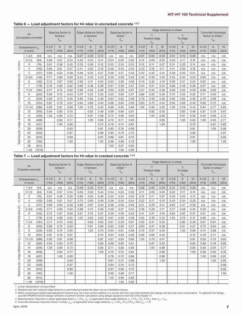
HIT-HY 100 Technical Supplement
7April 2018
Table 6 mdash Load adjustment factors for 4 rebar in uncracked concrete 123
4Uncracked concrete
Spacing factor in tension
fAN
Edge distance factor in tension
fRN
Spacing factor in shear 4
fAV
Edge distance in shearConcrete thickness
factor in shear 5
fHV
Toward edge
fRV
To edge
fRV
Embedment hefin (mm)
4-12 6 10 4-12 6 10 4-12 6 10 4-12 6 10 4-12 6 10 4-12 6 10 (114) (152) (254) (114) (152) (254) (114) (152) (254) (114) (152) (254) (114) (152) (254) (114) (152) (254)
Spac
ing
(s)
edg
e di
stan
ce (c
a) c
oncr
ete
thic
knes
s (h
) - i
n (m
m)
1-34 (44) na na na 027 020 012 na na na 007 005 003 014 010 006 na na na2-12 (64) 059 057 054 032 023 014 054 053 052 012 009 005 023 017 010 na na na
3 (76) 061 058 055 035 026 015 055 054 053 015 011 007 031 023 014 na na na4 (102) 065 061 057 041 030 018 056 055 054 023 018 011 041 030 018 na na na5 (127) 069 064 058 048 035 021 058 057 055 033 025 015 048 035 021 na na na
5-34 (146) 071 066 060 054 040 023 059 058 055 040 030 018 054 040 023 060 na na6 (152) 072 067 060 056 041 024 060 058 056 043 032 019 056 041 024 062 na na7 (178) 076 069 062 066 048 028 061 059 057 054 041 024 066 048 028 067 na na
7-14 (184) 077 070 062 068 050 029 062 059 057 057 043 026 068 050 029 068 062 na8 (203) 080 072 063 075 055 032 063 060 057 066 050 030 075 055 032 071 065 na9 (229) 083 075 065 085 062 036 064 062 058 079 059 036 085 062 036 076 069 na10 (254) 087 078 067 094 069 040 066 063 059 093 070 042 094 069 040 080 072 na
11-14 (286) 092 081 069 100 078 045 068 065 060 100 083 050 100 078 045 084 077 06512 (305) 094 083 070 083 048 069 066 061 092 055 083 048 087 079 06714 (356) 100 089 073 097 056 072 068 063 100 069 097 056 094 086 07216 (406) 094 077 100 065 075 071 065 085 100 065 100 092 07718 (457) 100 080 073 079 074 067 100 073 097 08220 (508) 083 081 082 076 069 081 100 08622 (559) 087 089 085 079 070 089 09124 (610) 090 097 088 081 072 097 09530 (762) 100 100 098 089 078 100 10036 (914) 100 097 084
gt 48 (1219) 100 095
Table 7 mdash Load adjustment factors for 4 rebar in cracked concrete 123
4Cracked concrete
Spacing factor in tension
fAN
Edge distance factor in tension
fRN
Spacing factor in shear 4
fAV
Edge distance in shearConcrete thickness
factor in shear 5
fHV
Toward edge
fRV
To edge
fRV
Embedment hefin (mm)
4-12 6 10 4-12 6 10 4-12 6 10 4-12 6 10 4-12 6 10 4-12 6 10 (114) (152) (254) (114) (152) (254) (114) (152) (254) (114) (152) (254) (114) (152) (254) (114) (152) (254)
Spac
ing
(s)
edg
e di
stan
ce (c
a) c
oncr
ete
thic
knes
s (h
) - i
n (m
m)
1-34 (44) na na na 049 045 041 na na na 006 005 003 013 010 006 na na na2-12 (64) 059 057 054 056 050 044 054 053 052 011 008 005 022 017 010 na na na
3 (76) 061 058 055 060 053 046 055 054 053 015 011 007 029 022 013 na na na4 (102) 065 061 057 070 060 049 056 055 054 022 017 010 045 034 020 na na na5 (127) 069 064 058 080 067 053 058 056 055 031 023 014 062 047 028 na na na
5-34 (146) 071 066 060 088 073 056 059 057 055 039 029 017 077 058 035 059 na na6 (152) 072 067 060 091 075 057 059 058 055 041 031 018 082 062 037 061 na na7 (178) 076 069 062 100 083 062 061 059 056 052 039 023 100 078 047 066 na na
7-14 (184) 077 070 062 085 063 061 059 057 055 041 025 082 049 067 061 na8 (203) 080 072 063 091 066 062 060 057 063 047 028 091 057 070 064 na9 (229) 083 075 065 100 070 064 061 058 075 057 034 100 068 074 068 na10 (254) 087 078 067 075 065 063 059 088 066 040 075 078 071 na
11-14 (286) 092 081 069 081 067 064 060 100 079 047 081 083 075 06412 (305) 094 083 070 085 068 065 061 087 052 085 086 078 06614 (356) 100 089 073 095 071 068 063 100 066 095 093 084 07116 (406) 094 077 100 075 070 064 080 100 099 090 07618 (457) 100 080 078 073 066 096 100 095 08120 (508) 083 081 075 068 100 100 08522 (559) 087 084 078 070 08924 (610) 090 087 080 072 09330 (762) 100 096 088 077 10036 (914) 100 096 082
gt 48 (1219) 100 0931 Linear interpolation not permitted2 Shaded area with reduced edge distance is permitted provided the rebar has no installation torque3 When combining multiple load adjustment factors (eg for a four-anchor pattern in a corner with thin concrete member) the design can become very conservative To optimize the design
use Hilti PROFIS Anchor Design software or perform anchor calculation using design equations from ACI 318 Chapter 174 Spacing factor reduction in shear applicable when ca lt 3hef ƒAV is applicable when edge distance ca lt 3hef If ca ge 3hef then ƒAV = ƒAN 5 Concrete thickness reduction factor in shear ƒHV is applicable when edge distance ca lt 3hef If ca ge 3hef then ƒHV = 10
8 April 2018
Table 8 mdash Load adjustment factors for 5 rebar in uncracked concrete 123
5Uncracked concrete
Spacing factor in tension
fAN
Edge distance factor in tension
fRN
Spacing factor in shear 4
fAV
Edge distance in shearConcrete thickness
factor in shear 5
fHV
Toward edge
fRV
To edge
fRV
Embedment hefin (mm)
5-58 7-12 12-12 5-58 7-12 12-12 5-58 7-12 12-12 5-58 7-12 12-12 5-58 7-12 12-12 5-58 7-12 12-12(143) (191) (318) (143) (191) (318) (143) (191) (318) (143) (191) (318) (143) (191) (318) (143) (191) (318)
Spac
ing
(s)
edg
e di
stan
ce (c
a) c
oncr
ete
thic
knes
s (h
) - i
n (m
m)
1-34 (44) na na na 025 019 011 na na na 005 004 002 010 007 004 na na na2-12 (64) 059 057 054 032 023 014 054 053 052 012 009 005 023 018 011 na na na
3 (76) 062 059 055 036 026 015 055 054 053 017 013 008 034 025 015 na na na4 (102) 065 061 057 041 030 018 056 055 054 024 018 011 041 030 018 na na na5 (127) 068 063 058 047 034 020 058 056 055 031 023 014 047 034 020 na na na
5-34 (146) 071 066 059 053 039 023 059 057 055 039 029 018 053 039 023 na na na6 (152) 071 066 060 054 039 023 059 058 055 040 030 018 054 039 023 060 na na7 (178) 074 068 061 060 044 026 060 058 056 048 036 022 060 044 026 064 na na
7-14 (184) 077 070 062 068 050 029 061 059 057 057 043 026 068 050 029 068 062 na8 (203) 080 072 063 075 055 032 063 061 058 067 050 030 075 055 032 071 065 na9 (229) 083 074 065 083 061 036 064 062 058 077 058 035 083 061 036 075 068 na10 (254) 086 077 066 090 066 039 065 063 059 088 066 040 090 066 039 078 071 na
11-14 (286) 091 081 069 100 077 045 068 065 061 100 083 050 100 077 045 085 077 06512 (305) 097 086 071 088 052 070 067 062 100 061 088 052 090 082 06914 (356) 100 090 074 099 058 073 069 064 073 099 058 096 087 07316 (406) 094 077 100 065 076 071 065 085 100 065 100 092 07718 (457) 099 079 071 078 073 067 099 071 096 08120 (508) 100 082 078 081 075 068 100 078 100 08522 (559) 085 084 083 077 070 084 08824 (610) 087 091 086 080 071 091 09230 (762) 090 097 088 082 073 097 09536 (914) 098 100 096 088 077 100 100
gt 48 (1219) 100 100 100 086
Table 9 mdash Load adjustment factors for 5 rebar in cracked concrete 123
5Cracked concrete
Spacing factor in tension
fAN
Edge distance factor in tension
fRN
Spacing factor in shear 4
fAV
Edge distance in shearConcrete thickness
factor in shear 5
fHV
Toward edge
fRV
To edge
fRV
Embedment hefin (mm)
5-58 7-12 12-12 5-58 7-12 12-12 5-58 7-12 12-12 5-58 7-12 12-12 5-58 7-12 12-12 5-58 7-12 12-12(143) (191) (318) (143) (191) (318) (143) (191) (318) (143) (191) (318) (143) (191) (318) (143) (191) (318)
Spac
ing
(s)
edg
e di
stan
ce (c
a) c
oncr
ete
thic
knes
s (h
) - i
n (m
m)
1-34 (44) na na na 046 043 040 na na na 005 003 002 009 007 004 na na na2-12 (64) 059 057 054 056 050 044 054 053 052 011 008 005 022 017 010 na na na
3 (76) 062 059 055 062 055 046 055 054 053 016 012 007 032 024 014 na na na4 (102) 065 061 057 070 060 049 056 055 054 022 017 010 045 034 020 na na na5 (127) 068 063 058 078 066 053 057 056 054 029 022 013 059 044 026 na na na
5-34 (146) 071 066 059 087 072 056 059 057 055 037 028 017 074 056 033 na na na6 (152) 071 066 060 088 073 056 059 057 055 038 029 017 076 057 034 059 na na7 (178) 074 068 061 096 078 059 060 058 056 045 034 020 090 068 041 063 na na
7-14 (184) 077 070 062 100 085 062 061 059 056 054 040 024 100 081 049 066 060 na8 (203) 080 072 063 091 066 062 060 057 063 047 028 091 057 070 064 na9 (229) 083 074 065 098 069 064 061 058 073 055 033 098 066 073 067 na10 (254) 086 077 066 100 073 065 062 059 083 062 037 100 073 077 070 na
11-14 (286) 091 081 069 081 067 064 060 100 079 047 081 083 075 06412 (305) 097 086 071 089 070 066 062 096 058 089 089 081 06814 (356) 100 090 074 097 072 068 063 100 069 097 094 085 07216 (406) 094 077 100 075 070 064 080 100 099 090 07618 (457) 099 079 077 072 066 093 100 094 08020 (508) 100 082 079 074 067 100 099 08322 (559) 085 082 076 069 100 08724 (610) 087 084 078 070 09030 (762) 090 087 080 072 09336 (914) 098 094 086 076 100
gt 48 (1219) 100 100 099 0851 Linear interpolation not permitted2 Shaded area with reduced edge distance is permitted provided the rebar has no installation torque3 When combining multiple load adjustment factors (eg for a four-anchor pattern in a corner with thin concrete member) the design can become very conservative To optimize the design
use Hilti PROFIS Anchor Design software or perform anchor calculation using design equations from ACI 318 Chapter 174 Spacing factor reduction in shear applicable when ca lt 3hef ƒAV is applicable when edge distance ca lt 3hef If ca ge 3hef then ƒAV = ƒAN 5 Concrete thickness reduction factor in shear ƒHV is applicable when edge distance ca lt 3hef If ca ge 3hef then ƒHV = 10
HIT-HY 100 Technical Supplement
9April 2018
Table 10 mdash Load adjustment factors for 6 rebar in uncracked concrete 123
6Uncracked concrete
Spacing factor in tension
fAN
Edge distance factor in tension
fRN
Spacing factor in shear 4
fAV
Edge distance in shearConcrete thickness
factor in shear 5
fHV
Toward edge
fRV
To edge
fRV
Embedment hefin (mm)
6-34 9 15 6-34 9 15 6-34 9 15 6-34 9 15 6-34 9 15 6-34 9 15 (171) (229) (381) (171) (229) (381) (171) (229) (381) (171) (229) (381) (171) (229) (381) (171) (229) (381)
Spac
ing
(s)
edg
e di
stan
ce (c
a) c
oncr
ete
thic
knes
s (h
) - i
n (m
m)
1-34 (44) na na na 024 018 010 na na na 004 003 002 007 006 003 na na na3-34 (95) 059 057 054 032 023 014 054 053 052 012 009 005 023 017 010 na na na
4 (102) 060 057 054 033 024 014 054 053 052 013 010 006 026 019 012 na na na5 (127) 062 059 056 037 027 016 055 054 053 018 013 008 036 027 016 na na na6 (152) 065 061 057 041 030 018 056 055 054 023 018 011 041 030 018 na na na8 (203) 070 065 059 051 037 022 058 057 055 036 027 016 051 037 022 na na na
8-12 (216) 071 066 059 053 039 023 059 057 055 040 030 018 053 039 023 060 na na10 (254) 075 069 061 063 046 027 061 059 056 051 038 023 063 046 027 065 na na
10-34 (273) 077 070 062 068 050 029 061 059 057 056 042 025 068 050 029 067 061 na12 (305) 080 072 063 075 055 032 063 060 057 066 050 030 075 055 032 071 065 na14 (356) 085 076 066 088 065 038 065 062 059 084 063 038 088 065 038 077 070 na16 (406) 090 080 068 100 074 043 067 064 060 100 077 046 100 074 043 082 075 na
16-34 (425) 091 081 069 077 045 068 065 060 082 049 077 045 084 076 06418 (457) 094 083 070 083 049 069 066 061 091 055 083 049 087 079 06720 (508) 099 087 072 092 054 071 067 062 100 064 092 054 092 084 07022 (559) 100 091 074 100 059 073 069 064 074 100 059 096 088 07424 (610) 094 077 065 075 071 065 085 065 100 092 07726 (660) 098 079 070 077 073 066 095 070 095 08028 (711) 100 081 076 080 074 067 100 076 099 08330 (762) 083 081 082 076 069 081 100 08636 (914) 090 097 088 081 072 097 095
gt 48 (1219) 100 100 100 092 080 100 100
Table 11 mdash Load adjustment factors for 6 rebar in cracked concrete 123
6Cracked concrete
Spacing factor in tension
fAN
Edge distance factor in tension
fRN
Spacing factor in shear 4
fAV
Edge distance in shearConcrete thickness
factor in shear 5
fHV
Toward edge
fRV
To edge
fRV
Embedment hefin (mm)
6-34 9 15 6-34 9 15 6-34 9 15 6-34 9 15 6-34 9 15 6-34 9 15 (171) (229) (381) (171) (229) (381) (171) (229) (381) (171) (229) (381) (171) (229) (381) (171) (229) (381)
Spac
ing
(s)
edg
e di
stan
ce (c
a) c
oncr
ete
thic
knes
s (h
) - i
n (m
m)
1-34 (44) na na na 044 042 039 na na na 003 003 002 007 005 003 na na na3-34 (95) 059 057 054 056 050 044 054 053 052 011 008 005 022 016 010 na na na
4 (102) 060 057 054 057 051 044 054 053 052 012 009 005 024 018 011 na na na5 (127) 062 059 056 063 056 047 055 054 053 017 012 007 034 025 015 na na na6 (152) 065 061 057 070 060 049 056 055 054 022 016 010 044 033 020 na na na8 (203) 070 065 059 084 070 055 058 057 055 034 025 015 068 051 030 na na na
8-12 (216) 071 066 059 088 072 056 059 057 055 037 028 017 075 055 033 059 na na10 (254) 075 069 061 099 080 060 060 058 056 048 035 021 095 071 042 064 na na
10-34 (273) 077 070 062 100 084 062 061 059 056 053 039 024 100 079 047 066 060 na12 (305) 080 072 063 091 066 062 060 057 063 046 028 091 056 070 063 na14 (356) 085 076 066 100 072 064 062 058 079 059 035 100 070 076 068 na16 (406) 090 080 068 078 066 063 059 097 071 043 078 081 073 na
16-34 (425) 091 081 069 081 067 064 060 100 077 046 081 083 075 06318 (457) 094 083 070 085 068 065 061 085 051 085 086 077 06520 (508) 099 087 072 091 070 067 062 100 060 091 090 082 06922 (559) 100 091 074 098 072 068 063 069 098 095 086 07224 (610) 094 077 100 074 070 064 079 100 099 089 07526 (660) 098 079 076 072 065 089 100 093 07828 (711) 100 081 079 073 067 099 097 08130 (762) 083 081 075 068 100 100 08436 (914) 090 087 080 071 092
gt 48 (1219) 100 099 090 078 1001 Linear interpolation not permitted2 Shaded area with reduced edge distance is permitted provided the rebar has no installation torque3 When combining multiple load adjustment factors (eg for a four-anchor pattern in a corner with thin concrete member) the design can become very conservative To optimize the design
use Hilti PROFIS Anchor Design software or perform anchor calculation using design equations from ACI 318 Chapter 174 Spacing factor reduction in shear applicable when ca lt 3hef ƒAV is applicable when edge distance ca lt 3hef If ca ge 3hef then ƒAV = ƒAN 5 Concrete thickness reduction factor in shear ƒHV is applicable when edge distance ca lt 3hef If ca ge 3hef then ƒHV = 10
10 April 2018
Table 12 mdash Load adjustment factors for 7 rebar in uncracked concrete 123
7Uncracked concrete
Spacing factor in tension
fAN
Edge distance factor in tension
fRN
Spacing factor in shear 4
fAV
Edge distance in shearConcrete thickness
factor in shear 5
fHV
Toward edge
fRV
To edge
fRV
Embedment hefin (mm)
7-78 10-12 17-12 7-78 10-12 17-12 7-78 10-12 17-12 7-78 10-12 17-12 7-78 10-12 17-12 7-78 10-12 17-12(200) (267) (445) (200) (267) (445) (200) (267) (445) (200) (267) (445) (200) (267) (445) (200) (267) (445)
Spac
ing
(s)
edg
e di
stan
ce (c
a) c
oncr
ete
thic
knes
s (h
) - i
n (m
m)
1-34 (44) na na na 023 017 010 na na na 003 002 001 005 004 002 na na na4-38 (111) 059 057 054 032 023 014 054 053 052 011 008 005 022 016 010 na na na
5 (127) 061 058 055 034 025 015 054 054 053 013 010 006 027 020 012 na na na6 (152) 063 060 056 037 028 016 055 054 053 017 013 008 035 026 016 na na na7 (178) 065 061 057 041 030 018 056 055 054 022 016 010 041 030 018 na na na8 (203) 067 063 058 045 033 019 057 056 054 027 020 012 045 033 019 na na na
9-78 (251) 071 066 059 053 039 023 059 057 055 037 028 017 053 039 023 059 na na10 (254) 071 066 060 054 040 023 059 057 055 038 028 017 054 040 023 059 na na12 (305) 075 069 061 065 048 028 060 059 056 049 037 022 065 048 028 065 na na
12-12 (318) 076 070 062 067 050 029 061 059 056 052 039 024 067 050 029 066 060 na14 (356) 080 072 063 075 055 033 062 060 057 062 046 028 075 055 033 070 063 na16 (406) 084 075 065 086 063 037 064 061 058 076 057 034 086 063 037 075 068 na18 (457) 088 079 067 097 071 042 066 063 059 091 068 041 097 071 042 079 072 na
19-12 (495) 091 081 069 100 077 045 067 064 060 100 076 046 100 077 045 082 075 06320 (508) 092 082 069 079 046 067 064 060 079 048 079 046 083 076 06422 (559) 097 085 071 087 051 069 066 061 092 055 087 051 087 079 06724 (610) 100 088 073 095 056 071 067 062 100 063 095 056 091 083 07026 (660) 091 075 100 060 073 069 063 071 100 060 095 086 07328 (711) 094 077 065 074 070 064 079 065 099 089 07530 (762) 098 079 070 076 071 065 087 070 100 093 07836 (914) 100 084 084 081 076 068 100 084 100 086
gt 48 (1219) 096 100 092 084 074 100 099
Table 13 mdash Load adjustment factors for 7 rebar in cracked concrete 123
7Cracked concrete
Spacing factor in tension
fAN
Edge distance factor in tension
fRN
Spacing factor in shear 4
fAV
Edge distance in shearConcrete thickness
factor in shear 5
fHV
Toward edge
fRV
To edge
fRV
Embedment hefin (mm)
7-78 10-12 17-12 7-78 10-12 17-12 7-78 10-12 17-12 7-78 10-12 17-12 7-78 10-12 17-12 7-78 10-12 17-12(200) (267) (445) (200) (267) (445) (200) (267) (445) (200) (267) (445) (200) (267) (445) (200) (267) (445)
Spac
ing
(s)
edg
e di
stan
ce (c
a) c
oncr
ete
thic
knes
s (h
) - i
n (m
m)
1-34 (44) na na na 043 041 038 na na na 003 002 001 006 005 003 na na na4-38 (111) 059 057 054 056 050 044 054 053 052 012 009 005 024 018 011 na na na
5 (127) 061 058 055 059 052 045 055 054 053 015 011 007 029 022 013 na na na6 (152) 063 060 056 064 056 047 056 055 053 019 014 009 038 029 017 na na na7 (178) 065 061 057 070 060 049 056 055 054 024 018 011 048 036 022 na na na8 (203) 067 063 058 076 064 052 057 056 054 029 022 013 059 044 026 na na na
9-78 (251) 071 066 059 087 072 056 059 058 055 040 030 018 081 060 036 060 na na10 (254) 071 066 060 088 073 056 059 058 055 041 031 018 082 062 037 061 na na12 (305) 075 069 061 100 082 061 061 059 056 054 041 024 100 081 049 066 na na
12-12 (318) 076 070 062 084 062 062 060 057 057 043 026 100 084 052 068 062 na14 (356) 080 072 063 091 066 063 061 058 068 051 031 091 061 072 065 na16 (406) 084 075 065 100 071 065 062 059 083 062 037 100 071 077 070 na18 (457) 088 079 067 076 067 064 060 099 074 045 076 081 074 na
19-12 (495) 091 081 069 080 068 065 061 100 084 050 080 085 077 06520 (508) 092 082 069 082 068 065 061 087 052 082 086 078 06622 (559) 097 085 071 087 070 067 062 100 060 087 090 082 06924 (610) 100 088 073 093 072 068 063 069 093 094 085 07226 (660) 091 075 099 074 070 064 078 099 098 089 07528 (711) 094 077 100 076 071 065 087 100 100 092 07830 (762) 098 079 078 073 066 096 096 08136 (914) 100 084 083 077 069 100 100 088
gt 48 (1219) 096 094 086 076 1001 Linear interpolation not permitted2 Shaded area with reduced edge distance is permitted provided the rebar has no installation torque3 When combining multiple load adjustment factors (eg for a four-anchor pattern in a corner with thin concrete member) the design can become very conservative To optimize the design
use Hilti PROFIS Anchor Design software or perform anchor calculation using design equations from ACI 318 Chapter 174 Spacing factor reduction in shear applicable when ca lt 3hef ƒAV is applicable when edge distance ca lt 3hef If ca ge 3hef then ƒAV = ƒAN 5 Concrete thickness reduction factor in shear ƒHV is applicable when edge distance ca lt 3hef If ca ge 3hef then ƒHV = 10
HIT-HY 100 Technical Supplement
11April 2018
Table 14 mdash Load adjustment factors for 8 rebar in uncracked concrete 123
8Uncracked concrete
Spacing factor in tension
fAN
Edge distance factor in tension
fRN
Spacing factor in shear 4
fAV
Edge distance in shearConcrete thickness
factor in shear 5
fHV
Toward edge
fRV
To edge
fRV
Embedment hefin (mm)
9 12 20 9 12 20 9 12 20 9 12 20 9 12 20 9 12 20 (229) (305) (508) (229) (305) (508) (229) (305) (508) (229) (305) (508) (229) (305) (508) (229) (305) (508)
Spac
ing
(s)
edg
e di
stan
ce (c
a) c
oncr
ete
thic
knes
s (h
) - i
n (m
m)
1-34 (44) na na na 023 017 010 na na na 002 002 001 005 003 002 na na na5 (127) 059 057 054 032 023 014 054 053 052 011 008 005 022 015 009 na na na6 (152) 061 058 055 035 026 015 055 054 053 014 010 006 029 020 012 na na na7 (178) 063 060 056 038 028 016 055 054 053 018 013 008 036 025 015 na na na8 (203) 065 061 057 041 030 018 056 055 053 022 015 009 041 030 018 na na na9 (229) 067 063 058 045 033 019 057 055 054 026 018 011 045 033 019 na na na10 (254) 069 064 058 048 036 021 058 056 054 031 022 013 048 036 021 na na na
11-14 (286) 071 066 059 053 039 023 059 057 055 037 026 016 053 039 023 058 na na12 (305) 072 067 060 057 042 024 059 057 055 040 028 017 057 042 024 060 na na14 (356) 076 069 062 066 049 029 061 058 056 051 036 022 066 049 029 065 na na
14-14 (362) 076 070 062 067 050 029 061 059 056 052 037 022 067 050 029 066 059 na16 (406) 080 072 063 076 056 033 062 060 057 062 044 026 076 056 033 070 062 na18 (457) 083 075 065 085 063 037 064 061 058 074 052 031 085 063 037 074 066 na20 (508) 087 078 067 095 070 041 065 062 059 087 061 037 095 070 041 078 069 na22 (559) 091 081 068 100 076 045 067 063 059 100 071 042 100 076 045 082 073 na
22-14 (565) 091 081 069 077 045 067 063 060 072 043 077 045 082 073 06224 (610) 094 083 070 083 049 068 064 060 081 048 083 049 085 076 06426 (660) 098 086 072 090 053 070 066 061 091 054 090 053 089 079 06728 (711) 100 089 073 097 057 071 067 062 100 061 097 057 092 082 06930 (762) 092 075 100 061 073 068 063 068 100 061 095 085 07236 (914) 100 080 073 077 072 065 089 073 100 093 078
gt 48 (1219) 090 098 086 079 071 100 098 100 091
Table 15 mdash Load adjustment factors for 8 rebar in cracked concrete 123
8Cracked concrete
Spacing factor in tension
fAN
Edge distance factor in tension
fRN
Spacing factor in shear 4
fAV
Edge distance in shearConcrete thickness
factor in shear 5
fHV
Toward edge
fRV
To edge
fRV
Embedment hefin (mm)
9 12 20 9 12 20 9 12 20 9 12 20 9 12 20 9 12 20 (229) (305) (508) (229) (305) (508) (229) (305) (508) (229) (305) (508) (229) (305) (508) (229) (305) (508)
Spac
ing
(s)
edg
e di
stan
ce (c
a) c
oncr
ete
thic
knes
s (h
) - i
n (m
m)
1-34 (44) na na na 042 040 038 na na na 002 002 001 005 003 002 na na na5 (127) 059 057 054 056 050 044 054 053 052 011 008 005 022 017 010 na na na6 (152) 061 058 055 060 053 046 055 054 053 015 011 007 029 022 013 na na na7 (178) 063 060 056 065 057 047 055 054 053 018 014 008 037 028 017 na na na8 (203) 065 061 057 070 060 049 056 055 054 023 017 010 045 034 020 na na na9 (229) 067 063 058 075 064 051 057 056 054 027 020 012 054 040 024 na na na10 (254) 069 064 058 080 067 053 058 056 055 031 024 014 063 047 028 na na na
11-14 (286) 071 066 059 087 072 056 059 057 055 038 028 017 075 056 034 059 na na12 (305) 072 067 060 091 075 057 059 058 055 041 031 019 083 062 037 061 na na14 (356) 076 069 062 100 083 062 061 059 056 052 039 023 100 078 047 066 na na
14-14 (362) 076 070 062 084 062 061 059 056 054 040 024 080 048 066 060 na16 (406) 080 072 063 091 066 062 060 057 064 048 029 091 057 070 064 na18 (457) 083 075 065 100 070 064 061 058 076 057 034 100 068 075 068 na20 (508) 087 078 067 075 065 063 059 089 067 040 075 079 071 na22 (559) 091 081 068 080 067 064 060 100 077 046 080 082 075 na
22-14 (565) 091 081 069 080 067 064 060 078 047 080 083 075 06324 (610) 094 083 070 085 069 065 061 088 053 085 086 078 06626 (660) 098 086 072 090 070 067 062 099 059 090 090 081 06928 (711) 100 089 073 095 072 068 063 100 066 095 093 084 07130 (762) 092 075 100 073 069 064 074 100 096 087 07436 (914) 100 080 078 073 066 097 100 096 081
gt 48 (1219) 090 087 081 072 100 100 0931 Linear interpolation not permitted2 Shaded area with reduced edge distance is permitted provided the rebar has no installation torque3 When combining multiple load adjustment factors (eg for a four-anchor pattern in a corner with thin concrete member) the design can become very conservative To optimize the design
use Hilti PROFIS Anchor Design software or perform anchor calculation using design equations from ACI 318 Chapter 174 Spacing factor reduction in shear applicable when ca lt 3hef ƒAV is applicable when edge distance ca lt 3hef If ca ge 3hef then ƒAV = ƒAN 5 Concrete thickness reduction factor in shear ƒHV is applicable when edge distance ca lt 3hef If ca ge 3hef then ƒHV = 10
12 April 2018
Table 16 mdash Load adjustment factors for 9 rebar in uncracked concrete 123
9Uncracked concrete
Spacing factor in tension
fAN
Edge distance factor in tension
fRN
Spacing factor in shear 4
fAV
Edge distance in shearConcrete thickness
factor in shear 5
fHV
Toward edge
fRV
To edge
fRV
Embedment hefin (mm)
10-18 13-12 22-12 10-18 13-12 22-12 10-18 13-12 22-12 10-18 13-12 22-12 10-18 13-12 22-12 10-18 13-12 22-12(257) (343) (572) (257) (343) (572) (257) (343) (572) (257) (343) (572) (257) (343) (572) (257) (343) (572)
Spac
ing
(s)
edg
e di
stan
ce (c
a) c
oncr
ete
thic
knes
s (h
) - i
n (m
m)
1-34 (44) na na na 022 016 010 na na na 002 001 001 004 003 002 na na na5-58 (143) 059 057 054 032 024 014 054 053 052 011 008 005 022 015 009 na na na
6 (152) 060 057 054 033 024 014 054 053 052 012 008 005 024 017 010 na na na7 (178) 062 059 055 036 026 015 055 054 053 015 011 006 030 021 013 na na na8 (203) 063 060 056 039 029 017 055 054 053 018 013 008 037 026 016 na na na9 (229) 065 061 057 042 031 018 056 055 053 022 016 009 042 031 018 na na na10 (254) 066 062 057 045 033 019 057 055 054 026 018 011 045 033 019 na na na12 (305) 070 065 059 052 038 022 058 056 055 034 024 014 052 038 022 na na na
12-78 (327) 071 066 060 056 041 024 059 057 055 038 027 016 056 041 024 059 na na14 (356) 073 067 060 061 045 026 059 057 055 043 030 018 061 045 026 061 na na16 (406) 076 070 062 069 051 030 061 059 056 052 037 022 069 051 030 066 na na
16-14 (413) 077 070 062 070 052 030 061 059 056 053 038 023 070 052 030 066 059 na18 (457) 080 072 063 078 057 033 062 060 057 062 044 026 078 057 033 070 062 na20 (508) 083 075 065 087 064 037 063 061 058 073 051 031 087 064 037 073 065 na22 (559) 086 077 066 095 070 041 065 062 058 084 059 036 095 070 041 077 069 na24 (610) 090 080 068 100 076 045 066 063 059 096 067 040 100 076 045 080 072 na
25-14 (641) 092 081 069 080 047 067 063 060 100 073 044 080 047 083 073 06226 (660) 093 082 069 083 048 068 064 060 076 046 083 048 084 075 06328 (711) 096 085 071 089 052 069 065 061 085 051 089 052 087 077 06530 (762) 099 087 072 095 056 070 066 061 094 057 095 056 090 080 06836 (914) 100 094 077 100 067 074 069 064 100 074 100 067 099 088 074
gt 48 (1219) 100 086 100 089 082 076 068 100 089 100 100 085
Table 17 mdash Load adjustment factors for 9 rebar in cracked concrete 123
9Cracked concrete
Spacing factor in tension
fAN
Edge distance factor in tension
fRN
Spacing factor in shear 4
fAV
Edge distance in shearConcrete thickness
factor in shear 5
fHV
Toward edge
fRV
To edge
fRV
Embedment hefin (mm)
10-18 13-12 22-12 10-18 13-12 22-12 10-18 13-12 22-12 10-18 13-12 22-12 10-18 13-12 22-12 10-18 13-12 22-12(257) (343) (572) (257) (343) (572) (257) (343) (572) (257) (343) (572) (257) (343) (572) (257) (343) (572)
Spac
ing
(s)
edg
e di
stan
ce (c
a) c
oncr
ete
thic
knes
s (h
) - i
n (m
m)
1-34 (44) na na na 041 039 038 na na na 002 001 001 004 003 002 na na na5-58 (143) 059 057 054 056 050 044 054 053 052 011 008 005 022 016 009 na na na
6 (152) 060 057 054 057 051 044 054 053 052 012 009 005 024 017 010 na na na7 (178) 062 059 055 061 054 046 055 054 053 015 011 007 030 022 013 na na na8 (203) 063 060 056 065 057 048 055 054 053 019 013 008 037 027 016 na na na9 (229) 065 061 057 070 060 049 056 055 053 022 016 010 044 032 019 na na na10 (254) 066 062 057 074 063 051 057 055 054 026 019 011 052 037 022 na na na12 (305) 070 065 059 084 070 055 058 057 055 034 025 015 068 049 029 na na na
12-78 (327) 071 066 060 088 073 056 059 057 055 038 027 016 076 054 033 059 na na14 (356) 073 067 060 094 077 058 060 058 055 043 031 019 086 062 037 062 na na16 (406) 076 070 062 100 084 062 061 059 056 053 038 023 100 075 045 066 na na
16-14 (413) 077 070 062 085 063 061 059 056 054 039 023 077 046 066 059 na18 (457) 080 072 063 091 066 062 060 057 063 045 027 090 054 070 063 na20 (508) 083 075 065 099 070 064 061 058 073 053 032 099 063 074 066 na22 (559) 086 077 066 100 074 065 062 059 085 061 036 100 073 077 069 na24 (610) 090 080 068 078 066 063 059 097 069 042 078 081 072 na
25-14 (641) 092 081 069 081 067 064 060 100 075 045 081 083 074 06326 (660) 093 082 069 082 068 064 060 078 047 082 084 075 06328 (711) 096 085 071 087 069 065 061 087 052 087 087 078 06630 (762) 099 087 072 091 070 066 062 097 058 091 090 081 06836 (914) 100 094 077 100 074 070 064 100 076 100 099 088 075
gt 48 (1219) 100 086 083 076 069 100 100 100 0861 Linear interpolation not permitted2 Shaded area with reduced edge distance is permitted provided the rebar has no installation torque3 When combining multiple load adjustment factors (eg for a four-anchor pattern in a corner with thin concrete member) the design can become very conservative To optimize the design
use Hilti PROFIS Anchor Design software or perform anchor calculation using design equations from ACI 318 Chapter 174 Spacing factor reduction in shear applicable when ca lt 3hef ƒAV is applicable when edge distance ca lt 3hef If ca ge 3hef then ƒAV = ƒAN 5 Concrete thickness reduction factor in shear ƒHV is applicable when edge distance ca lt 3hef If ca ge 3hef then ƒHV = 10
HIT-HY 100 Technical Supplement
13April 2018
Table 18 mdash Load adjustment factors for 10 rebar in uncracked concrete 123
10Uncracked concrete
Spacing factor in tension
fAN
Edge distance factor in tension
fRN
Spacing factor in shear 4
fAV
Edge distance in shearConcrete thickness
factor in shear 5
fHV
Toward edge
fRV
To edge
fRV
Embedment hefin (mm)
11-14 15 25 11-14 15 25 11-14 15 25 11-14 15 25 11-14 15 25 11-14 15 25 (286) (381) (635) (286) (381) (635) (286) (381) (635) (286) (381) (635) (286) (381) (635) (286) (381) (635)
Spac
ing
(s)
edg
e di
stan
ce (c
a) c
oncr
ete
thic
knes
s (h
) - i
n (m
m) 1-34 (44) na na na 022 016 009 na na na 002 001 001 003 002 001 na na na
6-14 (159) 059 057 054 033 024 014 054 053 052 011 008 005 022 016 010 na na na7 (178) 060 058 055 035 025 015 054 053 052 013 010 006 026 019 012 na na na8 (203) 062 059 055 037 027 016 055 054 053 016 012 007 031 023 014 na na na9 (229) 063 060 056 040 030 017 055 054 053 019 014 008 038 028 017 na na na10 (254) 065 061 057 043 032 019 056 055 054 022 016 010 043 032 019 na na na11 (279) 066 062 057 046 034 020 057 055 054 025 019 011 046 034 020 na na na12 (305) 068 063 058 049 036 021 057 056 054 029 022 013 049 036 021 na na na14 (356) 071 066 059 057 042 024 059 057 055 036 027 016 057 042 024 na na na
14-14 (362) 071 066 060 058 043 025 059 057 055 037 028 017 058 043 025 059 na na16 (406) 074 068 061 065 048 028 060 058 056 045 033 020 065 048 028 062 na na17 (432) 075 069 061 069 051 030 060 058 056 049 036 022 069 051 030 064 na na18 (457) 077 070 062 073 054 031 061 059 056 053 040 024 073 054 031 066 060 na20 (508) 080 072 063 081 060 035 062 060 057 062 046 028 081 060 035 070 063 na22 (559) 083 074 065 089 066 038 063 061 058 072 054 032 089 066 038 073 066 na24 (610) 086 077 066 098 072 042 065 062 059 082 061 037 098 072 042 076 069 na26 (660) 089 079 067 100 078 045 066 063 059 092 069 041 100 078 045 079 072 na28 (711) 091 081 069 084 049 067 064 060 100 077 046 084 049 082 075 06330 (762) 094 083 070 090 052 068 065 061 085 051 090 052 085 077 06536 (914) 100 090 074 100 063 072 068 063 100 067 100 063 094 085 072
gt 48 (1219) 100 082 084 079 074 067 100 084 100 098 083
Table 19 mdash Load adjustment factors for 10 rebar in cracked concrete 123
10Cracked concrete
Spacing factor in tension
fAN
Edge distance factor in tension
fRN
Spacing factor in shear 4
fAV
Edge distance in shearConcrete thickness
factor in shear 5
fHV
Toward edge
fRV
To edge
fRV
Embedment hefin (mm)
11-14 15 25 11-14 15 25 11-14 15 25 11-14 15 25 11-14 15 25 11-14 15 25 (286) (381) (635) (286) (381) (635) (286) (381) (635) (286) (381) (635) (286) (381) (635) (286) (381) (635)
Spac
ing
(s)
edg
e di
stan
ce (c
a) c
oncr
ete
thic
knes
s (h
) - i
n (m
m) 1-34 (44) na na na 040 039 037 na na na 002 001 001 003 002 001 na na na
6-14 (159) 059 057 054 056 050 044 054 053 052 011 007 004 022 015 009 na na na7 (178) 060 058 055 058 052 045 054 053 052 013 009 005 026 018 011 na na na8 (203) 062 059 055 062 055 046 055 054 053 016 011 006 032 022 013 na na na9 (229) 063 060 056 066 057 048 055 054 053 019 013 008 038 026 015 na na na10 (254) 065 061 057 070 060 049 056 055 053 022 015 009 044 030 018 na na na11 (279) 066 062 057 074 063 051 057 055 054 026 017 010 051 035 021 na na na12 (305) 068 063 058 078 066 053 057 056 054 029 020 012 058 040 024 na na na14 (356) 071 066 059 087 072 056 059 057 055 037 025 015 073 050 030 na na na
14-14 (362) 071 066 060 088 073 056 059 057 055 038 026 015 075 051 031 059 na na16 (406) 074 068 061 096 078 059 060 058 055 045 031 018 090 061 037 063 na na17 (432) 075 069 061 100 081 061 060 058 056 049 033 020 098 067 040 064 na na18 (457) 077 070 062 085 062 061 059 056 054 036 022 100 073 044 066 058 na20 (508) 080 072 063 091 066 062 059 057 063 043 026 085 051 070 061 na22 (559) 083 074 065 098 069 063 060 057 072 049 030 098 059 073 064 na24 (610) 086 077 066 100 073 065 061 058 082 056 034 100 067 077 067 na26 (660) 089 079 067 077 066 062 059 093 063 038 076 080 070 na28 (711) 091 081 069 081 067 063 059 100 071 042 081 083 073 06130 (762) 094 083 070 085 068 064 060 078 047 085 086 075 06436 (914) 100 090 074 097 072 067 062 100 062 097 094 082 070
gt 48 (1219) 100 082 100 079 073 066 095 100 100 095 0801 Linear interpolation not permitted2 Shaded area with reduced edge distance is permitted provided the rebar has no installation torque3 When combining multiple load adjustment factors (eg for a four-anchor pattern in a corner with thin concrete member) the design can become very conservative To optimize the design
use Hilti PROFIS Anchor Design software or perform anchor calculation using design equations from ACI 318 Chapter 174 Spacing factor reduction in shear applicable when ca lt 3hef ƒAV is applicable when edge distance ca lt 3hef If ca ge 3hef then ƒAV = ƒAN 5 Concrete thickness reduction factor in shear ƒHV is applicable when edge distance ca lt 3hef If ca ge 3hef then ƒHV = 10
14 April 2018
Hilti HIT-HY 100 adhesive with Hilti HAS threaded rod
HIT-VHAS
Hilti HAS HIT-V threaded rod installation conditions
Perm
issi
ble
Bas
e M
ater
ials
Uncracked concrete
DryConcrete
Perm
issi
ble
Dril
ling
Met
hod
Hammer Drilling with Carbide Tipped
Drill Bit
Cracked concrete
Water Saturated Concrete
Hollow Drill Bit
Hilti HASHIT-V threaded rod installation specifications
Nominal Rod
Diameter
Drill Bit Diameter
Embedment Depth Range
Maximum Installation
Torque
Minimum Base Material
Thickness
din (mm)
d0in
hefin (mm)
Tmaxft-lb (Nm)
hminin (mm)
38716
2-38 ndash 7-12 15hef + 1-14 (hef + 30)
(95) (60 ndash 191) (20)12
916 2-34 ndash 10 30
(127) (70 ndash 254) (41)58
343-18 ndash 12-12 60
hef + 2d0
(159) (79 ndash 318) (81)34
783-12 ndash 15 100
(191) (89 ndash 381) (136)78
13-12 ndash 17-12 125
(222) (89 ndash 445) (169)1
1-184 ndash 20 150
(254) (102 ndash 508) (203)1-14
1-385 ndash 25 200
(318) (127 ndash 635) (271)
min
max
df HASHIT-V 38 12 58 34 78 1 1-14
df1 12 58 1316 1516 1-18 1-14 1-12
df2 716 916 1116 1316 1516 1-18 1-38 Use two washers
HIT-HY 100 Technical Supplement
15April 2018
Table 20 mdash Hilti HIT-HY 100 adhesive design strength with concrete bond failure for threaded rod in uncracked concrete 12345678
Nominal anchor
diameterin
Effective embedment
in (mm)
Tension mdash ϕNn Shear mdash ϕVn
f´c = 2500 psi(172 Mpa)
lb (kN)
f´c = 3000 psi(207 Mpa)
lb (kN)
f´c = 4000 psi(276 Mpa)
lb (kN)
f´c = 6000 psi(414 Mpa)
lb (kN)
f´c = 2500 psi(172 Mpa)
lb (kN)
f´c = 3000 psi(207 Mpa)
lb (kN)
f´c = 4000 psi(276 Mpa)
lb (kN)
f´c = 6000 psi(414 Mpa)
lb (kN)
38
2-38 2710 2760 2840 2960 2920 2970 3060 3185(60) (121) (123) (126) (132) (130) (132) (136) (142)
3-38 3850 3920 4035 4205 8295 8445 8695 9055(86) (171) (174) (179) (187) (369) (376) (387) (403)
4-12 5135 5230 5380 5605 11060 11260 11590 12070(114) (228) (233) (239) (249) (492) (501) (516) (537)7-12 8555 8715 8970 9340 18430 18770 19320 20120(191) (381) (388) (399) (415) (820) (835) (859) (895)
12
2-34 3555 3895 4385 4565 7660 8395 9445 9835(70) (158) (173) (195) (203) (341) (373) (420) (437)
4-12 6845 6970 7175 7470 14745 15015 15455 16095(114) (304) (310) (319) (332) (656) (668) (687) (716)
6 9130 9295 9565 9965 19660 20020 20605 21460(152) (406) (413) (425) (443) (875) (891) (917) (955)10 15215 15495 15945 16605 32765 33370 34345 35765
(254) (677) (689) (709) (739) (1457) (1484) (1528) (1591)
58
3-18 4310 4720 5450 6485 9280 10165 11740 13970(79) (192) (210) (242) (288) (413) (452) (522) (621)
5-58 10405 10895 11210 11675 22415 23465 24150 25145(143) (463) (485) (499) (519) (997) (1044) (1074) (1119)7-12 14260 14525 14950 15565 30720 31285 32195 33530(191) (634) (646) (665) (692) (1366) (1392) (1432) (1491)
12-12 23770 24210 24915 25945 51200 52140 53660 55880(318) (1057) (1077) (1108) (1154) (2277) (2319) (2387) (2486)
34
3-12 5105 5595 6460 7910 11000 12050 13915 17040(89) (227) (249) (287) (352) (489) (536) (619) (758)
6-34 13680 14985 16145 16815 29460 32275 34775 36210(171) (609) (667) (718) (748) (1310) (1436) (1547) (1611)
9 20540 20915 21525 22415 44235 45050 46365 48280(229) (914) (930) (957) (997) (1968) (2004) (2062) (2148)
15 34230 34860 35875 37360 73725 75080 77275 80470(381) (1523) (1551) (1596) (1662) (3279) (3340) (3437) (3579)
78
3-12 5105 5595 6460 7910 11000 12050 13915 17040(89) (227) (249) (287) (352) (489) (536) (619) (758)7-78 17235 18885 20500 21350 37125 40670 44155 45980(200) (767) (840) (912) (950) (1651) (1809) (1964) (2045)
10-12 26080 26560 27335 28465 56170 57200 58870 61305(267) (1160) (1181) (1216) (1266) (2499) (2544) (2619) (2727)17-12 43465 44265 45555 47440 93615 95335 98120 102180(445) (1933) (1969) (2026) (2110) (4164) (4241) (4365) (4545)
1
4 6240 6835 7895 9665 13440 14725 17000 20820(102) (278) (304) (351) (430) (598) (655) (756) (926)
9 21060 23070 24465 25475 45360 49690 52690 54870(229) (937) (1026) (1088) (1133) (2018) (2210) (2344) (2441)
12 31120 31695 32620 33970 67030 68260 70255 73160(305) (1384) (1410) (1451) (1511) (2982) (3036) (3125) (3254)
20 51870 52820 54365 56615 111715 113770 117090 121935(508) (2307) (2350) (2418) (2518) (4969) (5061) (5208) (5424)
1-14
5 8720 9555 11030 12140 18785 20575 23760 29100(127) (388) (425) (491) (540) (836) (915) (1057) (1294)11-14 25025 25490 26230 27315 63395 64880 66770 69535(286) (1113) (1134) (1167) (1215) (2820) (2886) (2970) (3093)
15 33370 33985 34975 36425 84940 86505 89030 92710(381) (1484) (1512) (1556) (1620) (3778) (3848) (3960) (4124)25 55615 56640 58290 60705 141570 144175 148380 154520
(635) (2474) (2519) (2593) (2700) (6297) (6413) (6600) (6873)1 See Section 318 (2017 PTG) for explanation on development of load values2 See Section 3186 (2017 PTG) to convert design strength value to ASD value3 Linear interpolation between embedment depths and concrete compressive strengths is not permitted4 Load values are for a single anchor with no spacing edge distance or concrete thickness factors Apply spacing edge distance and concrete thickness factors in tables 23-35 as
necessary Compare to the steel values in table 22 The lesser of the values is to be used for the design5 Data is for temperature range A Max short term temperature = 130degF (55degC) max long term temperature = 110degF (43degC) For temperature range B Max short term temperature = 176degF (80degC) max long term temperature = 110degF (43degC) multiply above value by 092 For temperature range C Max short term temperature = 210degF (99degC) max long term temperature = 162degF (72degC) multiply above value by 071 Short term elevated concrete temperatures are those that occur over brief intervals eg as a result of diurnal cycling Long term concrete temperatures are roughly constant over significant periods of time6 Tabular values are for dry concrete conditions For water saturated concrete multiply design strength (factored resistance) by 0857 Tabular values are for short term loads only For sustained loads including overhead use see Section 3188 (2017 PTG)8 Tabular values are for normal-weight concrete only For lightweight concrete multiply design strength by λa as follows For sand-lightweight λa = 051 For all-lightweight λa = 045
16 April 2018
Table 21 mdash Hilti HIT-HY 100 adhesive design strength with concrete bond failure for threaded rod in cracked concrete 123456789
Nominal anchor
diameterin
Effective embedment
in (mm)
Tension mdash ϕNn Shear mdash ϕVn
f´c = 2500 psi(172 Mpa)
lb (kN)
f´c = 3000 psi(207 Mpa)
lb (kN)
f´c = 4000 psi(276 Mpa)
lb (kN)
f´c = 6000 psi(414 Mpa)
lb (kN)
f´c = 2500 psi(172 Mpa)
lb (kN)
f´c = 3000 psi(207 Mpa)
lb (kN)
f´c = 4000 psi(276 Mpa)
lb (kN)
f´c = 6000 psi(414 Mpa)
lb (kN)
38
2-38 1120 1140 1170 1220 1205 1225 1260 1315(60) (50) (51) (52) (54) (54) (54) (56) (58)
3-38 1590 1620 1665 1735 3425 3485 3590 3735(86) (71) (72) (74) (77) (152) (155) (160) (166)
4-12 2120 2160 2220 2315 4565 4650 4785 4980(114) (94) (96) (99) (103) (203) (207) (213) (222)7-12 3530 3595 3700 3855 7610 7750 7975 8305(191) (157) (160) (165) (171) (339) (345) (355) (369)
12
2-34 1880 1915 1970 2055 4050 4125 4245 4425(70) (84) (85) (88) (91) (180) (183) (189) (197)
4-12 3080 3135 3225 3360 6630 6750 6950 7235(114) (137) (139) (143) (149) (295) (300) (309) (322)
6 4105 4180 4300 4480 8840 9005 9265 9650(152) (183) (186) (191) (199) (393) (401) (412) (429)10 6840 6965 7170 7465 14735 15005 15445 16080
(254) (304) (310) (319) (332) (655) (667) (687) (715)
58
3-18 2890 2945 3030 3155 6230 6345 6530 6800(79) (129) (131) (135) (140) (277) (282) (290) (302)
5-58 5205 5300 5455 5680 11210 11415 11750 12235(143) (232) (236) (243) (253) (499) (508) (523) (544)7-12 6940 7065 7275 7575 14945 15220 15665 16315(191) (309) (314) (324) (337) (665) (677) (697) (726)
12-12 11565 11780 12125 12625 24910 25370 26110 27190(318) (514) (524) (539) (562) (1108) (1129) (1161) (1209)
34
3-12 3620 3965 4355 4535 7790 8535 9380 9765(89) (161) (176) (194) (202) (347) (380) (417) (434)
6-34 8010 8160 8395 8745 17255 17575 18085 18835(171) (356) (363) (373) (389) (768) (782) (804) (838)
9 10680 10880 11195 11660 23010 23430 24115 25115(229) (475) (484) (498) (519) (1024) (1042) (1073) (1117)
15 17805 18130 18660 19435 38345 39055 40190 41855(381) (792) (806) (830) (865) (1706) (1737) (1788) (1862)
78
3-12 3620 3965 4575 5325 7790 8535 9855 11470(89) (161) (176) (204) (237) (347) (380) (438) (510)7-78 10975 11175 11505 11980 23640 24075 24775 25800(200) (488) (497) (512) (533) (1052) (1071) (1102) (1148)
10-12 14635 14905 15340 15975 31520 32100 33035 34405(267) (651) (663) (682) (711) (1402) (1428) (1469) (1530)17-12 24390 24840 25565 26620 52530 53500 55060 57340(445) (1085) (1105) (1137) (1184) (2337) (2380) (2449) (2551)
1
4 4420 4840 5590 6845 9520 10430 12040 14750(102) (197) (215) (249) (304) (423) (464) (536) (656)
9 14520 14785 15220 15845 31270 31845 32775 34135(229) (646) (658) (677) (705) (1391) (1417) (1458) (1518)
12 19360 19715 20290 21130 41695 42460 43700 45510(305) (861) (877) (903) (940) (1855) (1889) (1944) (2024)
32265 32860 33815 35215 69490 70770 72835 75850(508) (1435) (1462) (1504) (1566) (3091) (3148) (3240) (3374)
1 See Section 318 (2017 PTG) for explanation on development of load values2 See Section 3186 (2017 PTG) to convert design strength value to ASD value3 Linear interpolation between embedment depths and concrete compressive strengths is not permitted4 Load values are for a single anchor with no spacing edge distance or concrete thickness factors Apply spacing edge distance and concrete thickness factors in tables 23-35 as
necessary Compare to the steel values in table 22 The lesser of the values is to be used for the design5 Data is for temperature range A Max short term temperature = 130degF (55degC) max long term temperature = 110degF (43degC) For temperature range B Max short term temperature = 176degF (80degC) max long term temperature = 110degF (43degC) multiply above value by 092 For temperature range C Max short term temperature = 210degF (99degC) max long term temperature = 162degF (72degC) multiply above value by 071 Short term elevated concrete temperatures are those that occur over brief intervals eg as a result of diurnal cycling Long term concrete temperatures are roughly constant over significant periods of time6 Tabular values are for dry concrete conditions For water saturated concrete multiply design strength (factored resistance) by 0857 Tabular values are for short term loads only For sustained loads including overhead use see Section 3188 (2017 PTG)8 Tabular values are for normal-weight concrete only For lightweight concrete multiply design strength by λa as follows For sand-lightweight λa = 051 For all-lightweight λa = 045 9 Tabular values are for static loads only For seismic loads multiply cracked concrete tabular values in tension and shear by αseis = 075
HIT-HY 100 Technical Supplement
17April 2018
Table 22 mdash Steel design strength HAS and HIT-V anchor threaded rods for use with ACI 318-14 Ch 17
Nominal anchor
diameterin
HIT-VASTM A307 Grade A 4
HAS-EISO 898 Class 58 4
HAS-E-B and HAS-E-B HDGASTM A193 B7 and
ASTM F 1554 Gr 105 5
Tensile1
ϕNsalb (kN)
Shear2
ϕVsalb (kN)
Seismic Shear3
ϕVsaeqlb (kN)
Tensile1
ϕNsalb (kN)
Shear2
ϕVsalb (kN)
Seismic Shear3
ϕVsaeqlb (kN)
Tensile1
ϕNsalb (kN)
Shear2
ϕVsalb (kN)
Seismic Shear3
ϕVsaeqlb (kN)
38 3025 1675 1175 3655 2020 1415 7265 3780 2645(135) (75) (52) (163) (90) (63) (323) (168) (118)
12 5535 3065 2145 6690 3705 2595 13300 6915 4840(246) (136) (95) (295) (165) (115) (592) (308) (215)
58 8815 4880 3415 10650 5900 4130 21190 11020 7715(392) (216) (152) (474) (262) (184) (943) (490) (343)
34 13045 7225 5060 15765 8730 6110 31360 16305 11415(580) (321) (225) (701) (388) (272) (1395) (725) (508)
78 - - - 21755 12050 8435 43285 22505 15755- - - (968) (536) (375) (1925) (1001) (701)
123620 13085 9160 28540 15805 11065 56785 29525 20670(1051) (582) (407) (1270) (703) (492) (2526) (1313) (919)
1-14- - - 45670 25295 17705 90850 47240 33070- - - (2003) (1125) (788) (4041) (2101) (1471)
1 Tensile = ϕ AseN futa as noted in ACI 318-14 174122 Shear = ϕ 060 AseV futa as noted in ACI 318-14 17512b3 Seismic Shear = αVseis ϕVsa Reduction factor for seismic shear only See ACI 318 for additional information on seismic applications 4 HIT-V and HAS-E threaded rods are considered brittle steel elements HIT-V does not comply with elongation requirements of ASTM A307 Grade A steel HAS-E does not comply with
elongation requirements of ISO 898-15 HAS-E-B and HAS-E-B HDG rods are considered ductile steel elements
Table 22 (Continued) mdash Steel design strength for Hilti HAS threaded rods for use with ACI 318 Chapter 17
Nominal anchor
diameterin
HAS-V HAS-V HDGASTM F1554 Gr 36 46
HAS-E HAS-E HDGASTM F1554 Gr 55 46
HAS-B and HAS-B HDGASTM A193 B7 and
ASTM F 1554 Gr 105 46
HAS-R Stainless SteelASTM F593 (38-in to 1-in) 5
ASTM A193 (1-18-in to 1-14-in)4
Tensile1
ϕNsalb (kN)
Shear2
ϕVsalb (kN)
Seismic Shear3
ϕVsaeqlb (kN)
Tensile1
ϕNsalb (kN)
Shear2
ϕVsalb (kN)
Seismic Shear3
ϕVsaeqlb (kN)
Tensile1
ϕNsalb (kN)
Shear2
ϕVsalb (kN)
Seismic Shear3
ϕVsaeqlb (kN)
Tensile1
ϕNsalb (kN)
Shear6
ϕVsalb (kN)
Seismic Shear3
ϕVsaeqlb (kN)
38 3370 1750 1050 4360 2270 1590 7270 3780 2645 5040 2790 1955(150) (78) (47) (194) (101) (71) (323) (168) (118) (224) (124) (87)
12 6175 3210 1925 7985 4150 2905 13305 6920 4845 9225 5110 3575(275) (143) (86) (355) (185) (129) (592) (308) (216) (410) (227) (159)
58 9835 5110 3065 12715 6610 4625 21190 11020 7715 14690 8135 5695(437) (227) (136) (566) (294) (206) (943) (490) (343) (653) (362) (253)
34 14550 7565 4540 18820 9785 6850 31360 16310 11415 18485 10235 7165(647) (337) (202) (837) (435) (305) (1395) (726) (508) (822) (455) (319)
78 20085 10445 6265 25975 13505 9455 43285 22510 15755 25510 14125 9890(893) (465) (279) (1155) (601) (421) (1925) (1001) (701) (1135) (628) (440)
126350 13700 8220 34075 17720 12405 56785 29530 20670 33465 18535 12975(1172) (609) (366) (1516) (788) (552) (2526) (1314) (919) (1489) (824) (577)
1-1442160 21920 13150 54515 28345 19840 90855 47245 33070 41430 21545 12925(1875) (975) (585) (2425) (1261) (883) (4041) (2102) (1471) (1843) (958) (575)
1 Tensile = ϕ AseN futa as noted in ACI 318-14 174122 Shear = ϕ 060 AseV futa as noted in ACI 318-14 17512b3 Seismic Shear = αVseis ϕVsa Reduction factor for seismic shear only See ACI 318 for additional information on seismic applications 4 HAS-V HAS-E HAS-B and HAS-R (Class 1 1-18-in to 1-14-in) threaded rods are considered ductile steel elements (included HDG rods)5 HAS-E-B and HAS-E-B HDG rods are
considered ductile steel elements 5 HAS-R (CW1 and CW2 38-in to 1-in) threaded rods are considered brittle steel elements (including HDG rods)6 38-inch dia threaded rods are not included in the ASTM F1554 standard Hilti 38-inch dia HAS-V HAS-E and HAS-E-B (incl HDG) threaded rods meet the chemical composition and
mechanical property requirements of ASTM F1554
18 April 2018
Table 23 mdash Load adjustment factors for 38-in diameter threaded rods in uncracked concrete 123
38-inUncracked concrete
Spacing factor in tension
fAN
Edge distance factor in tension
fRN
Spacing factor in shear 4
fAV
Edge distance in shearConcrete thickness
factor in shear 5
fHV
Toward edge
fRV
To edge
fRV
Embedment hefin (mm)
2-38 3-38 4-12 7-12 2-38 3-38 4-12 7-12 2-38 3-38 4-12 7-12 2-38 3-38 4-12 7-12 2-38 3-38 4-12 7-12 2-38 3-38 4-12 7-12(60) (86) (114) (191) (60) (86) (114) (191) (60) (86) (114) (191) (60) (86) (114) (191) (60) (86) (114) (191) (60) (86) (114) (191)
Spac
ing
(s)
edg
e di
stan
ce (c
a) c
oncr
ete
thic
knes
s (h
) - i
n (m
m)
1-34 (44) na na na na 041 031 023 013 na na na na 024 009 007 004 041 018 013 008 na na na na1-78 (48) 060 059 057 054 042 032 023 014 057 054 053 052 027 010 007 004 042 020 015 009 na na na na
2 (51) 061 060 057 054 044 033 024 014 057 054 053 052 029 011 008 005 044 022 016 010 na na na na3 (76) 067 065 061 057 057 041 030 017 061 056 055 053 054 020 015 009 057 040 030 017 na na na na
3-58 (92) 070 068 063 058 066 046 034 020 063 057 056 054 072 027 020 012 066 046 034 020 073 na na na4 (102) 072 070 065 059 072 050 036 021 065 058 056 055 083 031 023 014 072 050 036 021 077 na na na
4-58 (117) 075 073 067 060 084 056 041 024 067 059 057 055 100 038 029 017 084 056 041 024 083 059 na na5 (127) 077 075 069 061 091 061 044 026 068 060 058 056 043 032 019 091 061 044 026 086 062 na na
5-34 (146) 082 078 071 063 100 070 051 029 071 061 059 056 053 040 024 100 070 051 029 092 066 060 na6 (152) 083 080 072 063 073 053 031 072 061 059 057 056 042 025 073 053 031 094 068 061 na8 (203) 094 090 080 068 097 070 041 080 065 063 059 087 065 039 097 070 041 078 071 na
8-34 (222) 098 093 082 069 100 077 045 082 067 064 060 099 075 045 100 077 045 082 074 06210 (254) 100 099 087 072 088 051 087 069 066 061 100 091 055 088 051 087 079 06711 (279) 100 091 074 097 056 091 071 067 062 100 063 097 056 091 083 07012 (305) 094 077 100 061 094 073 069 063 072 061 095 087 07314 (356) 100 081 071 100 077 072 066 091 071 100 094 07916 (406) 086 082 080 075 068 100 082 100 08418 (457) 090 092 084 078 070 092 09024 (610) 100 100 096 088 077 100 10030 (762) 100 097 08336 (914) 100 090
gt 48 (1219) 100
Table 24 mdash Load adjustment factors for 38-in diameter threaded rods in cracked concrete 123
38-inCracked concrete
Spacing factor in tension
fAN
Edge distance factor in tension
fRN
Spacing factor in shear 4
fAV
Edge distance in shearConcrete thickness
factor in shear 5
fHV
Toward edge
fRV
To edge
fRV
Embedment hefin (mm)
2-38 3-38 4-12 7-12 2-38 3-38 4-12 7-12 2-38 3-38 4-12 7-12 2-38 3-38 4-12 7-12 2-38 3-38 4-12 7-12 2-38 3-38 4-12 7-12
(60) (86) (114) (191) (60) (86) (114) (191) (60) (86) (114) (191) (60) (86) (114) (191) (60) (86) (114) (191) (60) (86) (114) (191)
Spac
ing
(s)
edg
e di
stan
ce (c
a) c
oncr
ete
thic
knes
s (h
) - i
n (m
m)
1-34 (44) na na na na 056 054 049 043 na na na na 034 013 009 006 056 025 019 011 na na na na1-78 (48) 060 059 057 054 058 056 050 044 059 055 054 053 038 014 010 006 058 028 021 013 na na na na
2 (51) 061 060 057 054 060 057 051 044 059 055 054 053 042 015 012 007 060 031 023 014 na na na na3 (76) 067 065 061 057 074 070 060 049 064 057 056 054 076 028 021 013 074 056 042 025 na na na na
3-58 (92) 070 068 063 058 084 079 066 053 067 059 057 055 100 037 028 017 084 075 056 034 082 na na na4 (102) 072 070 065 059 090 084 070 055 069 060 058 056 043 033 020 090 084 065 039 086 na na na
4-58 (117) 075 073 067 060 100 093 076 058 071 061 059 057 054 040 024 100 093 076 048 093 066 na na5 (127) 077 075 069 061 099 080 060 073 062 060 057 061 045 027 099 080 054 096 069 na na
5-34 (146) 082 078 071 063 100 089 065 077 064 061 058 075 056 034 100 089 065 100 074 067 na6 (152) 083 080 072 063 091 066 078 064 062 058 080 060 036 091 066 076 069 na8 (203) 094 090 080 068 100 078 087 069 066 061 100 092 055 100 078 087 079 na
8-34 (222) 098 093 082 069 083 091 071 067 062 100 063 083 091 083 07010 (254) 100 099 087 072 091 096 074 070 064 077 091 098 089 07511 (279) 100 091 074 098 100 076 072 065 089 098 100 093 07912 (305) 094 077 100 079 074 067 100 100 097 08214 (356) 100 081 083 078 070 100 08916 (406) 086 088 082 072 09518 (457) 090 093 085 075 10024 (610) 100 100 097 08430 (762) 100 09236 (914) 100
gt 48 (1219)1 Linear interpolation not permitted2 Shaded area with reduced edge distance is permitted provided the installation torque is reduced to 030 Tmax for 5d le s le 16-in and to 05 Tmax for s gt 16-in3 When combining multiple load adjustment factors (eg for a four-anchor pattern in a corner with thin concrete member) the design can become very conservative To optimize the design
use Hilti PROFIS Anchor Design software or perform anchor calculation using design equations from ACI 318 Chapter 174 Spacing factor reduction in shear applicable when ca lt 3hef ƒAV is applicable when edge distance ca lt 3hef If ca ge 3hef then ƒAV = ƒAN 5 Concrete thickness reduction factor in shear ƒHV is applicable when edge distance ca lt 3hef If ca ge 3hef then ƒHV = 10
HIT-HY 100 Technical Supplement
19April 2018
Table 25 mdash Load adjustment factors for 12-in diameter threaded rods in uncracked concrete 123
12-inUncracked concrete
Spacing factor in tension
fAN
Edge distance factor in tension
fRN
Spacing factor in shear 4
fAV
Edge distance in shearConcrete thickness
factor in shear 5
fHV
Toward edge
fRV
To edge
fRV
Embedment hefin (mm)
2-34 4-12 6 10 2-34 4-12 6 10 2-34 4-12 6 10 2-34 4-12 6 10 2-34 4-12 6 10 2-34 4-12 6 10 (70) (114) (152) (254) (70) (114) (152) (254) (70) (114) (152) (254) (70) (114) (152) (254) (70) (114) (152) (254) (70) (114) (152) (254)
Spac
ing
(s)
edg
e di
stan
ce (c
a) c
oncr
ete
thic
knes
s (h
) - i
n (m
m) 1-34 (44) na na na na 037 027 020 012 na na na na 010 006 004 003 021 012 009 005 na na na na
2-12 (64) 060 059 057 054 045 031 023 013 055 054 053 052 018 010 007 004 035 020 015 009 na na na na3 (76) 062 061 058 055 050 034 025 015 056 054 054 053 023 013 010 006 046 026 019 012 na na na na4 (102) 067 065 061 057 061 040 029 017 058 056 055 053 036 020 015 009 061 040 029 017 058 na na na
5-34 (146) 074 071 066 060 088 051 038 022 062 058 057 055 061 034 026 016 088 051 038 022 069 057 na na6 (152) 075 072 067 060 092 053 039 023 063 059 057 055 065 037 028 017 092 053 039 023 071 058 na na7 (178) 079 076 069 062 100 062 045 026 065 060 058 056 082 046 035 021 100 062 045 026 077 063 na na
7-14 (184) 080 077 070 062 064 047 027 065 060 059 056 087 049 037 022 064 047 027 078 064 058 na8 (203) 083 080 072 063 070 052 030 067 061 059 057 100 056 042 025 070 052 030 082 068 061 na10 (254) 091 087 078 067 088 065 038 071 064 062 058 079 059 036 088 065 038 092 075 069 na
11-14 (286) 096 092 081 069 099 073 043 074 066 063 059 094 071 042 099 073 043 097 080 073 06112 (305) 099 094 083 070 100 078 045 075 067 064 060 100 078 047 100 078 045 100 083 075 06314 (356) 100 100 089 073 090 053 079 070 066 062 098 059 090 053 089 081 06816 (406) 094 077 100 061 084 073 069 063 100 072 100 061 095 087 07318 (457) 100 080 068 088 076 071 065 086 068 100 092 07820 (508) 083 076 092 078 074 067 100 076 097 08222 (559) 087 083 096 081 076 068 083 100 08624 (610) 090 091 100 084 078 070 091 09030 (762) 100 100 093 085 075 100 10036 (914) 100 092 080
gt 48 (1219) 100 090
Table 26 mdash Load adjustment factors for 12-in diameter threaded rods in cracked concrete 123
12-inCracked concrete
Spacing factor in tension
fAN
Edge distance factor in tension
fRN
Spacing factor in shear 4
fAV
Edge distance in shearConcrete thickness
factor in shear 5
fHV
Toward edge
fRV
To edge
fRV
Embedment hefin (mm)
2-34 4-12 6 10 2-34 4-12 6 10 2-34 4-12 6 10 2-34 4-12 6 10 2-34 4-12 6 10 2-34 4-12 6 10 (70) (114) (152) (254) (70) (114) (152) (254) (70) (114) (152) (254) (70) (114) (152) (254) (70) (114) (152) (254) (70) (114) (152) (254)
Spac
ing
(s)
edg
e di
stan
ce (c
a) c
oncr
ete
thic
knes
s (h
) - i
n (m
m) 1-34 (44) na na na na 051 049 045 041 na na na na 012 008 006 004 024 016 012 007 na na na na
2-12 (64) 060 059 057 054 058 056 050 044 056 054 054 053 021 014 010 006 042 027 021 012 na na na na3 (76) 062 061 058 055 063 060 053 046 057 055 054 053 027 018 014 008 055 036 027 016 na na na na4 (102) 067 065 061 057 074 070 060 049 059 057 056 054 042 028 021 013 074 056 042 025 061 na na na
5-34 (146) 074 071 066 060 096 089 073 056 064 060 058 056 073 048 036 022 096 089 072 043 073 064 na na6 (152) 075 072 067 060 099 091 075 057 064 061 059 056 077 051 038 023 099 091 075 046 075 065 na na7 (178) 079 076 069 062 100 100 083 062 066 062 060 057 098 064 048 029 100 100 083 058 081 071 na na
7-14 (184) 080 077 070 062 085 063 067 063 061 058 100 068 051 031 085 061 082 072 065 na8 (203) 083 080 072 063 091 066 069 064 062 058 079 059 035 091 066 087 075 068 na10 (254) 091 087 078 067 100 075 073 068 065 060 100 082 049 100 075 097 084 077 na
11-14 (286) 096 092 081 069 081 076 070 067 062 098 059 081 100 089 081 06812 (305) 099 094 083 070 085 078 071 068 063 100 065 085 092 084 07114 (356) 100 100 089 073 095 083 075 071 065 082 095 100 091 07616 (406) 094 077 100 088 078 073 067 100 100 100 097 08218 (457) 100 080 092 082 076 069 100 100 08720 (508) 083 097 086 079 071 09122 (559) 087 100 089 082 073 09624 (610) 090 093 085 075 10030 (762) 100 100 094 08136 (914) 100 088
gt 48 (1219) 1001 Linear interpolation not permitted2 Shaded area with reduced edge distance is permitted provided the installation torque is reduced to 030 Tmax for 5d le s le 16-in and to 05 Tmax for s gt 16-in3 When combining multiple load adjustment factors (eg for a four-anchor pattern in a corner with thin concrete member) the design can become very conservative To optimize the design
use Hilti PROFIS Anchor Design software or perform anchor calculation using design equations from ACI 318 Chapter 174 Spacing factor reduction in shear applicable when ca lt 3hef ƒAV is applicable when edge distance ca lt 3hef If ca ge 3hef then ƒAV = ƒAN 5 Concrete thickness reduction factor in shear ƒHV is applicable when edge distance ca lt 3hef If ca ge 3hef then ƒHV = 10
20 April 2018
Table 27 mdash Load adjustment factors for 58-in diameter threaded rods in uncracked concrete 123
58-inUncracked concrete
Spacing factor in tension
fAN
Edge distance factor in tension
fRN
Spacing factor in shear 4
fAV
Edge distance in shearConcrete thickness
factor in shear 5
fHV
Toward edge
fRV
To edge
fRV
Embedment hefin (mm)
3-18 5-58 7-12 12-12 3-18 5-58 7-12 12-12 3-18 5-58 7-12 12-12 3-18 5-58 7-12 12-12 3-18 5-58 7-12 12-12 3-18 5-58 7-12 12-12(79) (143) (191) (318) (79) (143) (191) (318) (79) (143) (191) (318) (79) (143) (191) (318) (79) (143) (191) (318) (79) (143) (191) (318)
Spac
ing
(s)
edg
e di
stan
ce (c
a) c
oncr
ete
thic
knes
s (h
) - i
n (m
m)
1-34 (44) na na na na 035 025 019 011 na na na na 009 004 003 002 019 009 006 004 na na na na3-18 (79) 060 059 057 054 048 031 023 013 056 054 053 052 022 010 007 004 045 020 015 009 na na na na
4 (102) 063 062 059 055 056 035 026 015 058 055 054 053 032 015 011 006 056 029 021 013 na na na na4-58 (117) 065 064 060 056 063 038 028 016 059 055 054 053 040 018 013 008 063 037 027 016 060 na na na
5 (127) 067 065 061 057 068 040 029 017 060 056 055 053 045 021 015 009 068 040 029 017 063 na na na6 (152) 070 068 063 058 081 045 033 019 062 057 056 054 059 027 020 012 081 045 033 019 069 na na na
7-18 (181) 073 071 066 060 095 051 037 022 064 058 057 055 077 035 025 015 095 051 037 022 075 058 na na8 (203) 076 074 068 061 100 056 041 024 066 059 058 055 091 042 030 018 100 056 041 024 079 061 na na10 (254) 083 080 072 063 070 052 030 070 062 059 057 100 058 042 025 070 052 030 089 068 061 na11 (279) 086 083 074 065 077 057 033 072 063 060 057 067 049 029 077 057 033 093 071 064 na12 (305) 090 086 077 066 084 062 036 074 064 061 058 076 056 033 084 062 036 097 075 067 na14 (356) 096 092 081 069 098 072 042 077 066 063 059 096 070 042 098 072 042 100 081 073 06116 (406) 100 097 086 071 100 083 048 081 069 065 061 100 086 051 100 083 048 086 078 06518 (457) 100 090 074 093 054 085 071 067 062 100 061 093 054 091 082 06920 (508) 094 077 100 060 089 073 069 063 072 100 060 096 087 07322 (559) 099 079 066 093 076 071 065 083 066 100 091 07724 (610) 100 082 072 097 078 073 066 094 072 095 08026 (660) 085 079 100 080 074 067 100 079 099 08328 (711) 087 085 083 076 069 085 100 08730 (762) 090 091 085 078 070 091 09036 (914) 098 100 092 084 074 100 098
gt 48 (1219) 100 100 095 082 100
Table 28 mdash Load adjustment factors for 58-in diameter threaded rods in cracked concrete 123
58-inCracked concrete
Spacing factor in tension
fAN
Edge distance factor in tension
fRN
Spacing factor in shear 4
fAV
Edge distance in shearConcrete thickness
factor in shear 5
fHV
Toward edge
fRV
To edge
fRV
Embedment hefin (mm)
3-18 5-58 7-12 12-12 3-18 5-58 7-12 12-12 3-18 5-58 7-12 12-12 3-18 5-58 7-12 12-12 3-18 5-58 7-12 12-12 3-18 5-58 7-12 12-12(79) (143) (191) (318) (79) (143) (191) (318) (79) (143) (191) (318) (79) (143) (191) (318) (79) (143) (191) (318) (79) (143) (191) (318)
Spac
ing
(s)
edg
e di
stan
ce (c
a) c
oncr
ete
thic
knes
s (h
) - i
n (m
m)
1-34 (44) na na na na 047 046 043 040 na na na na 009 006 004 003 019 011 009 005 na na na na3-18 (79) 060 059 057 054 058 056 050 044 056 054 054 053 023 014 010 006 045 027 020 012 na na na na
4 (102) 063 062 059 055 066 062 055 046 058 056 055 053 033 020 015 009 065 040 030 018 na na na na4-58 (117) 065 064 060 056 071 067 058 048 059 057 055 054 040 025 018 011 071 049 037 022 060 na na na
5 (127) 067 065 061 057 074 070 060 049 060 057 056 054 045 028 021 012 074 055 041 025 063 na na na6 (152) 070 068 063 058 084 078 066 053 062 059 057 055 060 036 027 016 084 073 054 033 069 na na na
7-18 (181) 073 071 066 060 095 088 073 056 064 060 058 056 077 047 035 021 095 088 070 042 075 063 na na8 (203) 076 074 068 061 100 096 078 059 066 061 059 057 092 056 042 025 100 096 078 050 079 067 na na10 (254) 083 080 072 063 100 091 066 070 064 062 058 100 078 059 035 100 091 066 089 075 068 na11 (279) 086 083 074 065 098 070 072 066 063 059 090 068 041 098 070 093 079 072 na12 (305) 090 086 077 066 100 073 074 067 064 060 100 077 046 100 073 097 082 075 na14 (356) 096 092 081 069 081 078 070 066 062 097 058 081 100 089 081 06816 (406) 100 097 086 071 089 082 073 069 063 100 071 089 095 086 07318 (457) 100 090 074 097 086 075 071 065 085 097 100 092 07720 (508) 094 077 100 089 078 073 067 099 100 097 08122 (559) 099 079 093 081 076 068 100 100 08524 (610) 100 082 097 084 078 070 08926 (660) 085 100 087 080 072 09328 (711) 087 090 083 073 09630 (762) 090 092 085 075 10036 (914) 098 100 092 080 100
gt 48 (1219) 100 100 0901 Linear interpolation not permitted2 Shaded area with reduced edge distance is permitted provided the installation torque is reduced to 030 Tmax for 5d le s le 16-in and to 05 Tmax for s gt 16-in3 When combining multiple load adjustment factors (eg for a four-anchor pattern in a corner with thin concrete member) the design can become very conservative To optimize the design
use Hilti PROFIS Anchor Design software or perform anchor calculation using design equations from ACI 318 Chapter 174 Spacing factor reduction in shear applicable when ca lt 3hef ƒAV is applicable when edge distance ca lt 3hef If ca ge 3hef then ƒAV = ƒAN 5 Concrete thickness reduction factor in shear ƒHV is applicable when edge distance ca lt 3hef If ca ge 3hef then ƒHV = 10
HIT-HY 100 Technical Supplement
21April 2018
Table 29 mdash Load adjustment factors for 34-in diameter threaded rods in uncracked concrete 123
34-inUncracked concrete
Spacing factor in tension
fAN
Edge distance factor in tension
fRN
Spacing factor in shear 4
fAV
Edge distance in shearConcrete thickness
factor in shear 5
fHV
Toward edge
fRV
To edge
fRV
Embedment hefin (mm)
3-12 6-34 9 15 3-12 6-34 9 15 3-12 6-34 9 15 3-12 6-34 9 15 3-12 6-34 9 15 3-12 6-34 9 15 (89) (171) (229) (381) (89) (171) (229) (381) (89) (171) (229) (381) (89) (171) (229) (381) (89) (171) (229) (381) (89) (171) (229) (381)
Spac
ing
(s)
edg
e di
stan
ce (c
a) c
oncr
ete
thic
knes
s (h
) - i
n (m
m)
1-34 (44) na na na na 035 024 018 010 na na na na 009 004 002 001 017 007 005 003 na na na na3-34 (95) 060 059 057 054 052 031 023 013 057 054 053 052 027 011 007 004 052 022 015 009 na na na na
4 (102) 061 060 057 054 054 032 023 014 057 054 053 052 029 012 008 005 054 024 016 010 na na na na5-14 (133) 064 063 060 056 066 037 027 016 060 055 054 053 044 018 012 007 066 036 024 014 062 na na na
6 (152) 067 065 061 057 074 040 029 017 061 056 055 053 054 022 015 009 074 040 029 017 067 na na na8 (203) 072 070 065 059 090 048 035 021 065 058 056 054 083 034 023 014 090 048 035 021 077 na na na
8-12 (216) 073 071 066 059 095 050 037 022 066 059 057 055 091 037 025 015 095 050 037 022 079 059 na na10 (254) 077 075 069 061 100 058 043 025 068 060 058 056 100 047 032 019 100 058 043 025 086 064 na na
10-34 (273) 080 077 070 062 063 046 027 070 061 058 056 053 035 021 063 046 027 089 066 058 na12 (305) 083 080 072 063 070 052 030 072 062 059 057 062 041 025 070 052 030 094 070 061 na14 (356) 088 085 076 066 082 060 035 076 064 061 058 078 052 031 082 060 035 100 075 066 na16 (406) 094 090 080 068 093 069 040 080 066 062 059 096 064 038 093 069 040 081 070 na
16-34 (425) 096 091 081 069 098 072 042 081 067 063 059 100 068 041 098 072 042 082 072 06118 (457) 099 094 083 070 100 077 045 083 068 064 060 076 046 100 077 045 085 075 06320 (508) 100 099 087 072 086 050 087 070 065 061 089 054 086 050 090 079 06622 (559) 100 091 074 094 055 091 072 067 062 100 062 094 055 094 082 07024 (610) 094 077 100 060 094 074 069 063 070 100 060 099 086 07326 (660) 098 079 065 098 076 070 064 079 065 100 090 07628 (711) 100 081 070 100 078 072 065 089 070 093 07830 (762) 083 075 080 073 067 098 075 096 08136 (914) 090 091 086 078 070 100 091 100 089
gt 48 (1219) 100 100 099 087 076 100 100
Table 30 mdash Load adjustment factors for 34-in diameter threaded rods in cracked concrete 123
34-inCracked concrete
Spacing factor in tension
fAN
Edge distance factor in tension
fRN
Spacing factor in shear 4
fAV
Edge distance in shearConcrete thickness
factor in shear 5
fHV
Toward edge
fRV
To edge
fRV
Embedment hefin (mm)
3-12 6-34 9 15 3-12 6-34 9 15 3-12 6-34 9 15 3-12 6-34 9 15 3-12 6-34 9 15 3-12 6-34 9 15 (89) (171) (229) (381) (89) (171) (229) (381) (89) (171) (229) (381) (89) (171) (229) (381) (89) (171) (229) (381) (89) (171) (229) (381)
Spac
ing
(s)
edg
e di
stan
ce (c
a) c
oncr
ete
thic
knes
s (h
) - i
n (m
m)
1-34 (44) na na na na 045 044 042 039 na na na na 009 004 003 002 017 009 006 004 na na na na3-34 (95) 060 059 057 054 058 056 050 044 057 054 054 053 027 013 010 006 054 027 020 012 na na na na
4 (102) 061 060 057 054 060 057 051 044 057 055 054 053 030 015 011 007 059 029 022 013 na na na na5-14 (133) 064 063 060 056 069 065 057 048 060 056 055 054 045 022 017 010 069 044 033 020 062 na na na
6 (152) 067 065 061 057 074 070 060 049 061 057 056 054 055 027 020 012 074 054 040 024 067 na na na8 (203) 072 070 065 059 090 084 070 055 065 059 058 055 084 041 031 019 090 083 062 037 077 na na na
8-12 (216) 073 071 066 059 095 088 072 056 066 060 058 056 092 045 034 020 095 088 068 041 079 063 na na10 (254) 077 075 069 061 100 099 080 060 069 062 060 057 100 058 043 026 100 099 080 052 086 068 na na
10-34 (273) 080 077 070 062 100 084 062 070 062 060 057 064 048 029 100 084 058 089 071 064 na12 (305) 083 080 072 063 091 066 072 064 061 058 076 057 034 091 066 094 075 068 na14 (356) 088 085 076 066 100 072 076 066 063 060 096 072 043 100 072 100 080 073 na16 (406) 094 090 080 068 078 080 069 065 061 100 088 053 078 086 078 na
16-34 (425) 096 091 081 069 081 081 069 066 061 094 056 081 088 080 06718 (457) 099 094 083 070 085 083 071 067 062 100 063 085 091 083 07020 (508) 100 099 087 072 091 087 073 069 064 074 091 096 087 07422 (559) 100 091 074 098 091 075 071 065 085 098 100 092 07724 (610) 094 077 100 095 078 073 066 097 100 096 08126 (660) 098 079 098 080 075 068 100 100 08428 (711) 100 081 100 082 077 069 100 08730 (762) 083 085 079 070 09036 (914) 090 092 084 074 099
gt 48 (1219) 100 100 096 083 1001 Linear interpolation not permitted2 Shaded area with reduced edge distance is permitted provided the installation torque is reduced to 030 Tmax for 5d le s le 16-in and to 05 Tmax for s gt 16-in3 When combining multiple load adjustment factors (eg for a four-anchor pattern in a corner with thin concrete member) the design can become very conservative To optimize the design
use Hilti PROFIS Anchor Design software or perform anchor calculation using design equations from ACI 318 Chapter 174 Spacing factor reduction in shear applicable when ca lt 3hef ƒAV is applicable when edge distance ca lt 3hef If ca ge 3hef then ƒAV = ƒAN 5 Concrete thickness reduction factor in shear ƒHV is applicable when edge distance ca lt 3hef If ca ge 3hef then ƒHV = 10
22 April 2018
Table 31 mdash Load adjustment factors for 78-in diameter threaded rods in uncracked concrete 123
78-inUncracked concrete
Spacing factor in tension
fAN
Edge distance factor in tension
fRN
Spacing factor in shear 4
fAV
Edge distance in shearConcrete thickness
factor in shear 5
fHV
Toward edge
fRV
To edge
fRV
Embedment hefin (mm)
3-12 7-78 10-12 17-12 3-12 7-78 10-12 17-12 3-12 7-78 10-12 17-12 3-12 7-78 10-12 17-12 3-12 7-78 10-12 17-12 3-12 7-78 10-12 17-12(89) (200) (267) (445) (89) (200) (267) (445) (89) (200) (267) (445) (89) (200) (267) (445) (89) (200) (267) (445) (89) (200) (267) (445)
Spac
ing
(s)
edg
e di
stan
ce (c
a) c
oncr
ete
thic
knes
s (h
) - i
n (m
m)
1-34 (44) na na na na 039 023 017 010 na na na na 009 003 002 001 018 006 004 002 na na na na4-38 (111) 061 059 057 054 059 031 023 013 058 054 053 052 035 011 007 004 059 022 014 009 na na na na
5 (127) 062 061 058 055 063 033 024 014 060 054 053 052 043 013 009 005 063 027 018 011 na na na na5-12 (140) 063 062 059 055 066 035 026 015 060 055 054 053 050 015 010 006 066 031 020 012 065 na na na
6 (152) 065 063 060 056 069 037 027 016 061 055 054 053 057 018 012 007 069 035 023 014 068 na na na8 (203) 070 067 063 058 083 044 032 019 065 057 055 054 087 027 018 011 083 044 032 019 078 na na na
9-78 (251) 074 071 066 059 097 051 038 022 069 059 057 055 100 037 024 015 097 051 038 022 087 059 na na10 (254) 074 071 066 060 098 052 038 022 069 059 057 055 038 025 015 098 052 038 022 087 059 na na12 (305) 079 075 069 061 062 045 027 073 060 058 056 049 033 020 062 045 027 096 065 na na
12-12 (318) 080 077 070 062 064 047 028 074 061 058 056 053 035 021 064 047 028 098 066 057 na14 (356) 084 080 072 063 072 053 031 077 062 059 057 062 041 025 072 053 031 100 070 061 na16 (406) 089 084 075 065 082 060 035 080 064 061 058 076 050 030 082 060 035 075 065 na18 (457) 094 088 079 067 092 068 040 084 066 062 058 091 060 036 092 068 040 079 069 na
19-12 (495) 098 091 081 069 100 074 043 087 067 063 059 100 068 041 100 074 043 082 072 06020 (508) 099 092 082 069 076 044 088 067 063 059 070 042 076 044 083 073 06122 (559) 100 097 085 071 083 049 092 069 065 060 081 049 083 049 087 076 06424 (610) 100 088 073 091 053 096 071 066 061 092 055 091 053 091 080 06726 (660) 091 075 098 058 099 073 067 062 100 063 098 058 095 083 07028 (711) 094 077 100 062 100 074 068 063 070 100 062 099 086 07230 (762) 098 079 066 100 076 070 064 077 066 100 089 07536 (914) 100 084 080 081 074 067 100 080 097 082
gt 48 (1219) 096 100 092 082 073 100 100 095
Table 32 mdash Load adjustment factors for 78-in diameter threaded rods in cracked concrete 123
78-inCracked concrete
Spacing factor in tension
fAN
Edge distance factor in tension
fRN
Spacing factor in shear 4
fAV
Edge distance in shearConcrete thickness
factor in shear 5
fHV
Toward edge
fRV
To edge
fRV
Embedment hefin (mm)
3-12 7-78 10-12 17-12 3-12 7-78 10-12 17-12 3-12 7-78 10-12 17-12 3-12 7-78 10-12 17-12 3-12 7-78 10-12 17-12 3-12 7-78 10-12 17-12(89) (200) (267) (445) (89) (200) (267) (445) (89) (200) (267) (445) (89) (200) (267) (445) (89) (200) (267) (445) (89) (200) (267) (445)
Spac
ing
(s)
edg
e di
stan
ce (c
a) c
oncr
ete
thic
knes
s (h
) - i
n (m
m)
1-34 (44) na na na na 044 043 041 038 na na na na 009 003 002 001 018 006 005 003 na na na na4-38 (111) 061 059 057 054 059 056 050 044 058 054 053 052 036 012 009 006 059 024 018 011 na na na na
5 (127) 062 061 058 055 063 059 052 045 060 055 054 053 043 015 011 007 063 030 022 013 na na na na5-12 (140) 063 062 059 055 066 062 054 046 061 055 054 053 050 017 013 008 066 034 026 016 065 na na na
6 (152) 065 063 060 056 069 064 056 047 062 056 055 053 057 020 015 009 069 039 029 018 068 na na na8 (203) 070 067 063 058 083 076 064 052 065 058 056 054 088 030 023 014 083 060 045 027 078 na na na
9-78 (251) 074 071 066 059 097 087 072 056 069 059 058 055 100 041 031 019 097 083 062 037 087 061 na na10 (254) 074 071 066 060 098 088 073 056 069 059 058 056 042 032 019 098 084 063 038 087 061 na na12 (305) 079 075 069 061 100 082 061 073 061 059 057 055 042 025 100 082 050 096 067 na na
12-12 (318) 080 077 070 062 084 062 074 062 060 057 059 044 027 084 053 098 068 062 na14 (356) 084 080 072 063 091 066 077 063 061 058 070 052 031 091 063 100 072 066 na16 (406) 089 084 075 065 100 071 081 065 062 059 085 064 038 100 071 077 070 na18 (457) 094 088 079 067 076 084 067 064 060 100 076 046 076 082 075 na
19-12 (495) 098 091 081 069 080 087 068 065 061 086 052 080 086 078 06620 (508) 099 092 082 069 082 088 069 066 061 089 054 082 087 079 06622 (559) 100 097 085 071 087 092 071 067 062 100 062 087 091 083 07024 (610) 100 088 073 093 096 073 069 063 071 093 095 086 07326 (660) 091 075 099 100 074 070 064 080 099 099 090 07628 (711) 094 077 100 100 076 072 065 089 100 100 093 07930 (762) 098 079 078 073 067 099 096 08136 (914) 100 084 084 078 070 100 100 089
gt 48 (1219) 096 095 087 076 1001 Linear interpolation not permitted2 Shaded area with reduced edge distance is permitted provided the installation torque is reduced to 030 Tmax for 5d le s le 16-in and to 05 Tmax for s gt 16-in3 When combining multiple load adjustment factors (eg for a four-anchor pattern in a corner with thin concrete member) the design can become very conservative To optimize the design
use Hilti PROFIS Anchor Design software or perform anchor calculation using design equations from ACI 318 Chapter 174 Spacing factor reduction in shear applicable when ca lt 3hef ƒAV is applicable when edge distance ca lt 3hef If ca ge 3hef then ƒAV = ƒAN 5 Concrete thickness reduction factor in shear ƒHV is applicable when edge distance ca lt 3hef If ca ge 3hef then ƒHV = 10
HIT-HY 100 Technical Supplement
23April 2018
Table 33 mdash Load adjustment factors for 1-in diameter threaded rods in uncracked concrete 123
1-inUncracked concrete
Spacing factor in tension
fAN
Edge distance factor in tension
fRN
Spacing factor in shear 4
fAV
Edge distance in shearConcrete thickness
factor in shear 5
fHV
Toward edge
fRV
To edge
fRV
Embedment hefin (mm)
4 9 12 20 4 9 12 20 4 9 12 20 4 9 12 20 4 9 12 20 4 9 12 20 (102) (229) (305) (508) (102) (229) (305) (508) (102) (229) (305) (508) (102) (229) (305) (508) (102) (229) (305) (508) (102) (229) (305) (508)
Spac
ing
(s)
edg
e di
stan
ce (c
a) c
oncr
ete
thic
knes
s (h
) - i
n (m
m)
1-34 (44) na na na na 038 023 017 010 na na na na 008 002 002 001 015 005 003 002 na na na na5 (127) 061 059 057 054 060 032 023 014 059 054 053 052 037 011 007 004 060 022 015 009 na na na na6 (152) 063 061 058 055 066 035 025 015 060 055 054 053 048 014 010 006 066 029 019 012 na na na na
6-14 (159) 064 062 059 055 068 035 026 015 061 055 054 053 051 015 010 006 068 030 021 012 065 na na na7 (178) 066 063 060 056 072 038 028 016 062 055 054 053 061 018 012 007 072 036 024 015 069 na na na8 (203) 068 065 061 057 078 041 030 018 064 056 055 053 074 022 015 009 078 041 030 018 074 na na na10 (254) 072 069 064 058 092 048 035 021 067 058 056 054 100 031 021 013 092 048 035 021 083 na na na
11-14 (286) 075 071 066 059 100 052 039 023 069 059 057 055 037 025 015 100 052 039 023 088 059 na na12 (305) 077 072 067 060 056 041 024 071 059 057 055 040 027 016 056 041 024 091 060 na na14 (356) 081 076 069 062 065 048 028 074 061 058 056 051 035 021 065 048 028 098 065 na na
14-14 (362) 082 076 070 062 066 049 029 074 061 058 056 052 035 021 066 049 029 099 066 058 na16 (406) 086 080 072 063 074 055 032 077 062 059 057 062 042 025 074 055 032 100 070 061 na18 (457) 090 083 075 065 084 062 036 081 064 061 058 074 050 030 084 062 036 074 065 na20 (508) 095 087 078 067 093 068 040 084 065 062 058 087 059 035 093 068 040 078 068 na22 (559) 099 091 081 068 100 075 044 088 067 063 059 100 068 041 100 075 044 082 072 na
22-14 (565) 100 091 081 069 076 045 088 067 063 059 100 069 041 076 045 082 072 06124 (610) 100 094 083 070 082 048 091 068 064 060 077 046 082 048 085 075 06326 (660) 098 086 072 089 052 094 070 065 061 087 052 089 052 089 078 06628 (711) 100 089 073 096 056 098 071 066 062 098 059 096 056 092 081 06830 (762) 092 075 100 060 100 073 068 063 100 065 100 060 095 084 07136 (914) 100 080 072 077 071 065 085 072 100 092 077
gt 48 (1219) 090 096 086 078 070 100 096 100 089
Table 34 mdash Load adjustment factors for 1-in diameter threaded rods in cracked concrete 123
1-inCracked concrete
Spacing factor in tension
fAN
Edge distance factor in tension
fRN
Spacing factor in shear 4
fAV
Edge distance in shearConcrete thickness
factor in shear 5
fHV
Toward edge
fRV
To edge
fRV
Embedment hefin (mm)
4 9 12 20 4 9 12 20 4 9 12 20 4 9 12 20 4 9 12 20 4 9 12 20 (102) (229) (305) (508) (102) (229) (305) (508) (102) (229) (305) (508) (102) (229) (305) (508) (102) (229) (305) (508) (102) (229) (305) (508)
Spac
ing
(s)
edg
e di
stan
ce (c
a) c
oncr
ete
thic
knes
s (h
) - i
n (m
m)
1-34 (44) na na na na 043 042 040 038 na na na na 008 002 002 001 015 005 004 002 na na na na5 (127) 061 059 057 054 060 056 050 044 059 054 053 052 037 011 008 005 060 023 017 010 na na na na6 (152) 063 061 058 055 066 060 053 046 060 055 054 053 049 015 011 007 066 030 022 013 na na na na
6-14 (159) 064 062 059 055 068 061 054 046 061 055 054 053 052 016 012 007 068 032 024 014 066 na na na7 (178) 066 063 060 056 072 065 057 048 062 055 055 053 061 019 014 008 072 037 028 017 069 na na na8 (203) 068 065 061 057 078 070 060 049 064 056 055 054 075 023 017 010 078 046 034 021 074 na na na10 (254) 072 069 064 058 092 080 067 053 067 058 056 055 100 032 024 014 092 064 048 029 083 na na na
11-14 (286) 075 071 066 059 100 087 072 056 069 059 057 055 038 029 017 100 076 057 034 088 059 na na12 (305) 077 072 067 060 091 075 057 071 059 058 056 042 031 019 084 063 038 091 061 na na14 (356) 081 076 069 062 100 083 062 074 061 059 056 053 040 024 100 079 048 098 066 na na
14-14 (362) 082 076 070 062 084 062 075 061 059 057 054 041 024 081 049 099 067 061 na16 (406) 086 080 072 063 091 066 078 062 060 057 065 048 029 091 058 100 071 064 na18 (457) 090 083 075 065 100 070 081 064 062 058 077 058 035 100 069 075 068 na20 (508) 095 087 078 067 075 084 066 063 059 090 068 041 075 079 072 na22 (559) 099 091 081 068 080 088 067 064 060 100 078 047 080 083 075 na
22-14 (565) 100 091 081 069 080 088 067 064 060 079 048 080 083 076 06424 (610) 100 094 083 070 085 091 069 065 061 089 053 085 086 079 06626 (660) 098 086 072 090 095 070 067 062 100 060 090 090 082 06928 (711) 100 089 073 095 098 072 068 063 067 095 093 085 07230 (762) 092 075 100 100 073 069 064 075 100 097 088 07436 (914) 100 080 078 073 066 098 100 096 081
gt 48 (1219) 090 087 081 072 100 100 0941 Linear interpolation not permitted2 Shaded area with reduced edge distance is permitted provided the installation torque is reduced to 030 Tmax for 5d le s le 16-in and to 05 Tmax for s gt 16-in3 When combining multiple load adjustment factors (eg for a four-anchor pattern in a corner with thin concrete member) the design can become very conservative To optimize the design
use Hilti PROFIS Anchor Design software or perform anchor calculation using design equations from ACI 318 Chapter 174 Spacing factor reduction in shear applicable when ca lt 3hef ƒAV is applicable when edge distance ca lt 3hef If ca ge 3hef then ƒAV = ƒAN 5 Concrete thickness reduction factor in shear ƒHV is applicable when edge distance ca lt 3hef If ca ge 3hef then ƒHV = 10
24 April 2018
Table 35 mdash Load adjustment factors for 1-14-in diameter threaded rods in uncracked concrete 123
1-14-inUncracked concrete
Spacing factor in tension
fAN
Edge distance factor in tension
fRN
Spacing factor in shear 4
fAV
Edge distance in shearConcrete thickness
factor in shear 5
fHV
Toward edge
fRV
To edge
fRV
Embedment hefin (mm)
5 11-14 15 25 5 11-14 15 25 5 11-14 15 25 5 11-14 15 25 5 11-14 15 25 5 11-14 15 25 (127) (286) (381) (635) (127) (286) (381) (635) (127) (286) (381) (635) (127) (286) (381) (635) (127) (286) (381) (635) (127) (286) (381) (635)
Spac
ing
(s)
edg
e di
stan
ce (c
a) c
oncr
ete
thic
knes
s (h
) - i
n (m
m)
1-34 (44) na na na na 037 022 016 009 na na na na 005 002 001 001 011 003 002 001 na na na na6-14 (159) 062 059 057 054 063 032 024 014 059 054 053 052 037 011 008 005 063 022 016 010 na na na na
7 (178) 064 060 058 055 067 034 025 015 060 054 054 053 044 013 010 006 067 026 019 012 na na na na8 (203) 066 062 059 055 073 037 027 016 061 055 054 053 053 016 012 007 073 032 024 014 066 na na na9 (229) 068 063 060 056 078 040 029 017 062 056 055 053 063 019 014 008 078 038 028 017 070 na na na10 (254) 070 065 061 057 084 043 032 019 064 056 055 054 074 022 016 010 084 043 032 019 074 na na na11 (279) 072 066 062 057 090 046 034 020 065 057 056 054 086 025 019 011 090 046 034 020 078 na na na12 (305) 074 068 063 058 096 049 036 021 066 057 056 054 098 029 022 013 096 049 036 021 081 na na na13 (330) 076 069 064 059 100 053 039 023 068 058 057 055 100 033 024 015 100 053 039 023 084 na na na14 (356) 078 071 066 059 057 042 024 069 059 057 055 036 027 016 057 042 024 088 058 na na
14-14 (362) 078 071 066 060 058 042 025 070 059 057 055 037 028 017 058 042 025 088 059 na na15 (381) 080 072 067 060 061 045 026 071 059 058 055 040 030 018 061 045 026 091 060 na na16 (406) 082 074 068 061 065 048 028 072 060 058 056 045 033 020 065 048 028 094 062 na na17 (432) 084 075 069 061 069 051 030 073 060 059 056 049 036 022 069 051 030 096 064 na na18 (457) 086 077 070 062 073 054 031 075 061 059 056 053 040 024 073 054 031 099 066 060 na20 (508) 090 080 072 063 081 059 035 077 062 060 057 062 046 028 081 059 035 100 070 063 na22 (559) 094 083 074 065 089 065 038 080 063 061 058 072 054 032 089 065 038 073 066 na24 (610) 098 086 077 066 097 071 042 083 065 062 059 082 061 037 097 071 042 076 069 na26 (660) 100 089 079 067 100 077 045 086 066 063 059 092 069 041 100 077 045 080 072 na28 (711) 092 081 069 083 049 088 067 064 060 100 077 046 083 049 083 075 06330 (762) 094 083 070 089 052 091 068 065 061 085 051 089 052 085 077 06536 (914) 100 090 074 100 063 099 072 068 063 100 067 100 063 094 085 072
gt 48 (1219) 100 082 084 100 079 074 067 100 084 100 098 0831 Linear interpolation not permitted2 Shaded area with reduced edge distance is permitted provided the installation torque is reduced to 030 Tmax for 5d le s le 16-in and to 05 Tmax for s gt 16-in3 When combining multiple load adjustment factors (eg for a four-anchor pattern in a corner with thin concrete member) the design can become very conservative To optimize the design
use Hilti PROFIS Anchor Design software or perform anchor calculation using design equations from ACI 318 Chapter 174 Spacing factor reduction in shear applicable when ca lt 3hef ƒAV is applicable when edge distance ca lt 3hef If ca ge 3hef then ƒAV = ƒAN 5 Concrete thickness reduction factor in shear ƒHV is applicable when edge distance ca lt 3hef If ca ge 3hef then ƒHV = 10
HIT-HY 100 Technical Supplement
25April 2018
Hilti HIT-HY 100 adhesive with Hilti HIS-N and HIS-RN internally threaded insert
Hilti HIS-N and HIS-RN internally threaded insert installation conditions
Perm
issi
ble
Bas
e M
ater
ials
Uncracked concrete
DryConcrete
Perm
issi
ble
Dril
ling
Met
hod
Hammer Drilling with Carbide Tipped
Drill Bit
Water Saturated Concrete
Hollow Drill Bit
Hilti HIS-N and HIS-RN installation specificationsInternal Nominal
Rod Diameter
InsertExternal Diameter
DrillBit Diameter
Embedment Depth
BoltEmbedment
Maximum Installation
Torque
Minimum Base Material
Thickness
din (mm)
Din (mm)
d0in
hefin (mm)
hsin
Tmaxft-lb (Nm)
hminin (mm)
38 0651116
4-3838 ndash 1516
15 59(95) (165) (110) (20) (150)12 081
785
12 ndash 1-31630 67
(127) (205) (125) (41) (170)58 100
1-186-34
58 ndash 1-1260 91
(159) (254) (170) (81) (230)34 109
1-148-18
34 ndash 1-78100 106
(191) (276) (205) (136) (270)
min
max
26 April 2018
Table 36 mdash Hilti HIT-HY 100 adhesive design strength with concrete bond failure for Hilti HIS-N and HIS-RN internally threaded inserts in uncracked concrete 12345678
Thread size
Effective Embedment
Depth in (mm)
Tension mdash ФNn Shear mdash ФVn
f´c = 2500 psi (172 MPa)
lb (kN)
f´c = 3000 psi (207 MPa)
lb (kN)
f´c = 4000 psi (276 MPa)
lb (kN)
f´c = 6000 psi (414 MPa)
lb (kN)
f´c = 2500 psi(172 MPa)
lb (kN)
f´c = 3000 psi(207 MPa)
lb (kN)
f´c = 4000 psi(276 MPa)
lb (kN)
f´c = 6000 psi(414 MPa)
lb (kN)
38-16 UNC
4-38 7140 7820 7985 8465 15375 16840 17200 18230(111) (318) (348) (355) (377) (684) (749) (765) (811)
12-13 UNC
5 8720 9555 10505 11135 18785 20575 22620 23980(127) (388) (425) (467) (495) (836) (915) (1006) (1067)
58-11 UNC
6-34 13680 14985 15160 16070 29460 32275 32655 34615(171) (609) (667) (674) (715) (1310) (1436) (1453) (1540)
34-10 UNC
8-18 15760 15760 15760 16705 38910 40120 40120 42530(206) (701) (701) (701) (743) (1731) (1785) (1785) (1892)
1 Table values determined from calculations according to ACI 318-11 Appendix D See Section 24 for explanation on development of load values2 See Section 3186 (2017 PTG) to convert design strength value to ASD value3 Linear interpolation between embedment depths and concrete compressive strengths is not permitted4 Apply spacing edge distance and concrete thickness factors in table 38 as necessary Compare to the steel values in table 37
The lesser of the values is to be used for the design5 Data is for temperature range A Max short term temperature = 130degF (55degC) max long term temperature = 110degF (43degC)
For temperature range B Max short term temperature = 176degF (80degC) max long term temperature = 110degF (43degC) multiply above value by 092 For temperature range C Max short term temperature = 210degF (99degC) max long term temperature = 162degF (72degC) multiply above value by 071 Short term elevated concrete temperatures are those that occur over brief intervals eg as a result of diurnal cycling Long term concrete temperatures are roughly constant over significant periods of time
6 Tabular values are for dry concrete conditions For water saturated concrete multiply design strength by 0857 Tabular values are for short term loads only For sustained loads including overhead use see Section 3188 (2017 PTG)8 Tabular values are for normal weight concrete only For lightweight concrete multiply design strength by λa as follows
For sand-lightweight λa = 051 For all-lightweight λa = 045
Table 37 mdash Steel design strength for steel bolt cap screw for Hilti HIS-N and HIS-RN internally threaded inserts 123
Thread size
ASTM A 193 B7ASTM A 193 Grade B8M
Stainless SteelTensile4
ϕNsalb (kN)
Shear5
ϕVsalb (kN)
Tensile4
ϕNsa
lb (kN)
Shear5
ϕVsa
lb (kN)
38-16 UNC6300 3490 5540 3070(280) (155) (246) (137)
12-13 UNC10525 6385 10145 5620(468) (284) (451) (250)
58-11 UNC17500 10170 16160 8950(778) (452) (719) (398)
34-10 UNC17785 15055 23915 13245(791) (670) (1064) (589)
1 See Section 244 (2017 PTG) to convert design strength value to ASD value2 Hilti HIS-N and HIS-RN inserts with steel bolts are considered brittle steel elements3 Table values are the lesser of steel failure in the HIS-N insert or inserted steel bolt4 Tensile = ϕ AseN futa as noted in ACI 318 Appendix D5 Shear = ϕ 060 AseV futa as noted in ACI 318 Appendix D For 38-in diameter insert shear = ϕ 050 AseV futa
HIT-HY 100 Technical Supplement
27April 2018
Table 38 mdash Load adjustment factors for Hilti HIS-N and HIS-RN internally threaded inserts in uncracked concrete 123 HIS-N and HIS-RN
All DiametersUncracked Concrete
Spacing Factor in Tension
fAN
Edge Distance Factor in Tension
fRN
Spacing Factor in Shear4
fAV
Edge Distance in ShearConcrete Thickness
Factor in Shear5
fHV
Toward Edge
fRV
To Edge
fRV
Internal Diameterin (mm)
38 12 58 34 38 12 58 34 38 12 58 34 38 12 58 34 38 12 58 34 38 12 58 34(95) (127) (159) (191) (95) (127) (159) (191) (95) (127) (159) (191) (95) (127) (159) (191) (95) (127) (159) (191) (95) (127) (159) (191)
Embedment hef in (mm)
4-38 5 6-34 8-18 4-38 5 6-34 8-18 4-38 5 6-34 8-18 4-38 5 6-34 8-18 4-38 5 6-34 8-18 4-38 5 6-34 8-18(111) (127) (171) (206) (111) (127) (171) (206) (111) (127) (171) (206) (111) (127) (171) (206) (111) (127) (171) (206) (111) (127) (171) (206)
Spac
ing
(s)
Edg
e D
ista
nce
(ca)
Con
cret
e Th
ickn
ess
(h)
mdash in
(mm
)
3-14 (83) 061 na na na 040 na na na 055 na na na 015 na na na 031 na na na na na na na
4 (102) 063 061 na na 045 043 na na 056 055 na na 021 019 na na 042 038 na na na na na na
5 (127) 067 064 062 na 052 049 044 na 057 057 055 na 029 026 017 na 052 049 033 na na na na na
5-12 (140) 068 065 063 061 056 052 046 040 058 058 056 055 034 030 019 015 056 052 039 029 na na na na
6 (152) 070 067 065 062 059 055 049 042 059 058 056 055 039 035 022 017 059 055 044 033 060 na na na
7 (178) 073 070 067 064 068 062 053 046 060 060 057 056 049 043 028 021 068 062 053 042 064 062 na na
8 (203) 077 072 069 066 077 070 058 050 062 061 058 057 060 053 034 026 077 070 058 051 069 066 na na
9 (229) 080 075 072 068 087 078 063 054 063 062 059 058 071 063 040 031 087 078 063 056 073 070 na na
10 (254) 083 078 074 071 097 087 069 059 065 064 060 058 083 074 047 036 097 087 069 061 077 074 064 na
11 (279) 087 081 077 073 100 096 075 063 066 065 061 059 096 086 055 041 100 096 075 065 081 078 067 061
12 (305) 090 083 079 075 100 082 069 068 066 062 060 100 098 062 047 100 082 069 084 081 070 064
14 (356) 097 089 084 079 096 081 071 069 064 062 100 078 059 096 081 091 087 075 069
16 (406) 100 095 089 083 100 092 074 072 066 063 096 073 100 092 097 094 080 073
18 (457) 100 094 087 100 077 075 068 065 100 087 100 100 099 085 078
24 (610) 100 099 085 083 074 070 100 100 099 090
30 (762) 100 094 091 080 075 100 100
36 (914) 100 099 086 080
gt48 (1219) 100 099 090
1 Linear interpolation not permitted2 When combining multiple load adjustment factors (eg for a four-anchor pattern in a corner with thin concrete member) the design can become very conservative To optimize the design perform
anchor calculation using design equations from ACI 318 Appendix D or CSA A233 Annex D3 Spacing factor reduction in shear f AV assumes an influence of a nearby edge If no edge exists then f AV = fAN4 Spacing factor reduction in shear applicable when c lt 3hef ƒAV is applicable when edge distance c lt 3hef If c ge 3hef then ƒAV = ƒAN 5 Concrete thickness reduction factor in shear ƒHV is applicable when edge distance c lt 3hef If c ge 3hef then ƒHV = 10
28 April 2018
Table 39 mdash Hilti HIT-HY 100 adhesive design information with CA rebar in hammer drilled holes in accordance with CSA A233-14 Annex D 1
Design parameter Symbol UnitsRebar size Ref
A233-1410M 15M 20M 25M 30M
Anchor OD d0 mm 113 160 195 252 299Effective minimum embedment 2 hefmin mm 70 80 90 101 120Effective maximum embedment 2 hefmax mm 226 320 390 504 598Min concrete thickness 2 hmin mm hef + 30 hef + 2d0
Critical edge distance cac - See ESR-3187 section 4110Minimum edge distance cmin
3 mm 57 80 98 126 150Minimum anchor spacing smin mm 57 80 98 126 150Coeff for factored conc breakout resistance uncracked concrete kcuncr
4 - 10 D622
Coeff for factored conc breakout resistance cracked concrete kccr
4 - 7 D622
Concrete material resistance factor fc - 065 842Resistance modification factor for tension and shear concrete failure modes Condition B 5
Rconc
-100 D53 (c )
Tem
p
rang
e A
6 Characteristic bond stress in cracked concrete 7 τcr
psi 625 725 775 790 800D652
(MPa) (43) (50) (54) (54) (55)Characteristic bond stress in uncracked concrete 7 τuncr
psi 1275 1255 1240 1220 1095D652
(MPa) (88) (87) (86) (84) (76)
Tem
p
rang
e B
6 Characteristic bond stress in cracked concrete 7 τcr
psi 575 665 725 725 735D652
(MPa) (40) (46) (49) (50) (51)Characteristic bond stress in uncracked concrete 7 τuncr
psi 1175 1155 1140 1120 1010D652
(MPa) (81) (80) (79) (77) (70)
Tem
p
rang
e C
6 Characteristic bond stress in cracked concrete 7 τcr
psi 440 510 545 555 560D652
(MPa) (30) (35) (38) (38) (39)Characteristic bond stress in uncracked concrete 7 τuncr
psi 915 900 885 875 785D652
(MPa) (63) (62) (61) (60) (54)Reduction for seismic tension αNseis - 100
D53 (c )
Perm
issi
ble
inst
alla
tion
cond
ition
s Resistance modification factor tension amp shear bond failure water-saturated concrete
Anchor category - 1 2
Rws - 100 085
1 Design information in this table is taken from ICC-ES ESR-3574 dated March 2018 table 20 and 21 and converted for use with CSA A233-14 Annex D2 See figure at the beginning of the rebar section3 Minimum edge distance may be reduced to 45mm provided rebar remains untorqued See ESR-3574 section 41924 For all design cases ψcN = 10 The appropriate coefficient for breakout resistance for cracked concrete (kccr) or uncracked concrete (kcuncr) must be used5 For use with the load combinations of CSA A233-14 chapter 8 Condition B applies where supplementary reinforcement in conformance with CSA A233-14
section D53 is not provided or where pullout or pryout strength governs For cases where the presence of supplementary reinforcement can be verified the resistance modification factors associated with Condition A may be used
6 Temperature range A Max short term temperature = 130degF (55degC) max long term temperature = 110degF (43degC) Temperature range B Max short term temperature = 176degF (80degC) max long term temperature = 110degF (43degC) Temperature range C Max short term temperature = 210degF (99degC) max long term temperature = 162degF (72degC) Short term elevated concrete temperatures are those that occur over brief intervals eg as a result of diurnal cycling Long term concrete temperatures are roughly constant over significant periods of time
7 Bond strength values corresponding to concrete compressive strength f´c = 2500 psi (172 MPa) For concrete compressive strength f´c between 2500 psi (172 MPa) and 8000 psi (552 MPa) the tabulated characteristic bond strength may be increased by a factor of (f´c2500)01 [for SI (f´c 172)01]
DESIGN DATA IN CONCRETE PER CSA A233 CSA A233-14 Annex D design Limit State Design of anchors is described in the provisions of CSA A233-14 Annex D for post-installed anchors tested and assessed in accordance with ACI 3552 for mechanical anchors and ACI 3554 for adhesive anchors This section contains the Limit State Design tables with unfactored characteristic loads that are based on testing in accordance with ACI 3554 These tables are followed by factored resistance tables The factored resistance tables have characteristic design loads that are prefactored by the applicable reduction factors for a single anchor with no anchor-to-anchor spacing or edge distance adjustments for the convenience of the user of this document All the figures in the previous ACI 318-14 Chapter 17 design section are applicable to Limit State Design and the tables will reference these figures
For a detailed explanation of the tables developed in accordance with CSA A233-14 Annex D refer to Section 318 of the Hilti North American Product Technical Guide Volume 2 Anchor Fastening Technical Guide Edition 17 Technical assistance is available by contacting Hilti Canada at (800) 363-4458 or at wwwhiltica
HIT-HY 100 Technical Supplement
29April 2018
Table 40 mdash Hilti HIT-HY 100 adhesive factored resistance with concrete bond failure for CA rebar in uncracked concrete 12345678
Rebar sizeEffective
embedmentin (mm)
Tension mdash Nr Shear mdash Vr
f´c = 20 MPa(2900 psi)
lb (kN)
f´c = 25 MPa(3625 psi)
lb (kN)
f´c = 30 MPa(4350 psi)
lb (kN)
f´c = 40 MPa(5800 psi)
lb (kN)
f´c = 20 MPa(2900 psi)
lb (kN)
f´c = 25 MPa(3625 psi)
lb (kN)
f´c = 30 MPa(4350 psi)
lb (kN)
f´c = 40 MPa(5800 psi)
lb (kN)
10M
4-12 5325 5445 5545 5710 10650 10890 11090 11415(115) (237) (242) (247) (254) (474) (484) (493) (508)
7-116 8335 8525 8680 8935 16670 17045 17360 17865(180) (371) (379) (386) (397) (742) (758) (772) (795)8-78 10465 10700 10900 11215 20930 21405 21795 22435(226) (466) (476) (485) (499) (931) (952) (970) (998)
15M
5-1116 9360 9570 9745 10030 18715 19140 19490 20060(145) (416) (426) (433) (446) (833) (851) (867) (892)
9-1316 16135 16500 16800 17295 32270 33000 33605 34585(250) (718) (734) (747) (769) (1435) (1468) (1495) (1538)
12-58 20655 21120 21505 22135 41305 42235 43015 44270(320) (919) (939) (957) (985) (1837) (1879) (1913) (1969)
20M
7-78 15545 15895 16185 16660 31085 31790 32375 33320(200) (691) (707) (720) (741) (1383) (1414) (1440) (1482)
14 27590 28210 28730 29570 55180 56425 57465 59140(355) (1227) (1255) (1278) (1315) (2454) (2510) (2556) (2631)
15-38 30310 30995 31565 32485 60620 61985 63130 64970(390) (1348) (1379) (1404) (1445) (2696) (2757) (2808) (2890)
25M
9-116 22725 23240 23670 24360 45455 46480 47335 48715(230) (1011) (1034) (1053) (1084) (2022) (2068) (2106) (2167)
15-1516 40020 40925 41675 42890 80040 81845 83350 85785(405) (1780) (1820) (1854) (1908) (3560) (3641) (3708) (3816)
19-1316 49805 50925 51865 53375 99605 101855 103725 106755(504) (2215) (2265) (2307) (2374) (4431) (4531) (4614) (4749)
30M
10-14 23255 23780 24220 24925 46510 47560 48435 49850(260) (1034) (1058) (1077) (1109) (2069) (2116) (2155) (2217)
17-1516 40700 41615 42380 43620 81395 83235 84765 87240(455) (1810) (1851) (1885) (1940) (3621) (3702) (3771) (3881)
23-916 53490 54695 55705 57330 106980 109390 111405 114655(598) (2379) (2433) (2478) (2550) (4759) (4866) (4956) (5100)
1 See Section 318 (2017 PTG) for explanation on development of load values2 See Section 3186 (2017 PTG) to convert design strength value to ASD value3 Linear interpolation between embedment depths and concrete compressive strengths is not permitted4 Apply spacing edge distance and concrete thickness factors in tables 43-52 as necessary Compare to the steel values in table 42
The lesser of the values is to be used for the design5 Data is for temperature range A Max short term temperature = 130degF (55degC) max long term temperature = 110degF (43degC)
For temperature range B Max short term temperature = 176degF (80degC) max long term temperature = 110degF (43degC) multiply above value by 092 For temperature range C Max short term temperature = 210degF (99degC) max long term temperature = 162degF (72degC) multiply above value by 071 Short term elevated concrete temperatures are those that occur over brief intervals eg as a result of diurnal cycling Long term concrete temperatures are roughly constant over significant periods of time
6 Tabular values are for dry concrete conditions For water saturated concrete multiply design strength (factored resistance) by 0857 Tabular values are for short term loads only For sustained loads including overhead use see Section 3188 (2017 PTG)8 Tabular values are for normal-weight concrete only For lightweight concrete multiply design strength by la as follows
For sand-lightweight λa = 051 For all-lightweight λa = 045
Hilti HIT-HY 100 Adhesive with Deformed Reinforcing Bars (Rebar)
30 April 2018
Table 41 mdash Hilti HIT-HY 100 adhesive factored resistance with concrete bond failure for CA rebar in cracked concrete 123456789
Rebar size
Effective embedment
in (mm)
Tension mdash Nr Shear mdash Vr
f´c = 20 MPa(2900 psi)
lb (kN)
f´c = 25 MPa(3625 psi)
lb (kN)
f´c = 30 MPa(4350 psi)
lb (kN)
f´c = 40 MPa(5800 psi)
lb (kN)
f´c = 20 MPa(2900 psi)
lb (kN)
f´c = 25 MPa(3625 psi)
lb (kN)
f´c = 30 MPa(4350 psi)
lb (kN)
f´c = 40 MPa(5800 psi)
lb (kN)
da (in) hef (in) 20 25 30 40 20 25 30 40
10M
4-12 2610 2670 2720 2800 5220 5340 5435 5595(115) (116) (119) (121) (124) (232) (237) (242) (249)
7-116 4085 4180 4255 4380 8170 8355 8510 8760(180) (182) (186) (189) (195) (364) (372) (379) (390)8-78 5130 5245 5340 5500 10260 10490 10685 10995(226) (228) (233) (238) (245) (456) (467) (475) (489)
15M
5-1116 5405 5530 5630 5795 10810 11055 11260 11590(145) (240) (246) (250) (258) (481) (492) (501) (515)
9-1316 9320 9530 9705 9990 18640 19065 19415 19980(250) (415) (424) (432) (444) (829) (848) (864) (889)
12-58 11930 12200 12425 12785 23860 24400 24850 25575(320) (531) (543) (553) (569) (1061) (1085) (1105) (1138)
20M
7-78 9715 9935 10115 10410 19430 19870 20235 20825(200) (432) (442) (450) (463) (864) (884) (900) (926)
14 17245 17635 17955 18480 34485 35265 35915 36960(355) (767) (784) (799) (822) (1534) (1569) (1598) (1644)
15-38 18945 19370 19725 20305 37885 38740 39455 40605(390) (843) (862) (878) (903) (1685) (1723) (1755) (1806)
25M
9-116 14715 15050 15325 15775 29435 30100 30650 31545(230) (655) (669) (682) (702) (1309) (1339) (1363) (1403)
15-1516 25915 26500 26985 27775 51830 53000 53975 55550(405) (1153) (1179) (1200) (1235) (2305) (2357) (2401) (2471)
19-1316 32250 32975 33585 34565 64500 65955 67165 69130(504) (1435) (1467) (1494) (1537) (2869) (2934) (2988) (3075)
30M
10-14 16990 17375 17695 18210 33980 34750 35390 36420(260) (756) (773) (787) (810) (1512) (1546) (1574) (1620)
17-1516 29735 30405 30965 31870 59470 60810 61930 63735(455) (1323) (1352) (1377) (1418) (2645) (2705) (2755) (2835)
23-916 39080 39960 40695 41885 78160 79920 81390 83765(598) (1738) (1778) (1810) (1863) (3477) (3555) (3620) (3726)
1 See Section 318 (2017 PTG) for explanation on development of load values2 See Section 3186 (2017 PTG) to convert design strength value to ASD value3 Linear interpolation between embedment depths and concrete compressive strengths is not permitted4 Apply spacing edge distance and concrete thickness factors in tables 43-52 as necessary Compare to the steel values in table 42
The lesser of the values is to be used for the design5 Data is for temperature range A Max short term temperature = 130degF (55degC) max long term temperature = 110degF (43degC)
For temperature range B Max short term temperature = 176degF (80degC) max long term temperature = 110degF (43degC) multiply above value by 092 For temperature range C Max short term temperature = 210degF (99degC) max long term temperature = 162degF (72degC) multiply above value by 071 Short term elevated concrete temperatures are those that occur over brief intervals eg as a result of diurnal cycling Long term concrete temperatures are roughly constant over significant periods of time
6 Tabular values are for dry concrete conditions For water saturated concrete multiply design strength (factored resistance) by 0857 Tabular values are for short term loads only For sustained loads including overhead use see Section 3188 (2017 PTG)8 Tabular values are for normal-weight concrete only For lightweight concrete multiply design strength by la as follows
For sand-lightweight λa = 051 For all-lightweight λa = 045 9 Tabular values are for static loads only For seismic loads multiply cracked concrete tabular values in tension and shear by αseis = 075
HIT-HY 100 Technical Supplement
31April 2018
Table 42 mdash Steel factored resistance for CA rebar 1
Rebar size
CSA-G3018 Grade 400 2
Tensile3
Nsarlb (kN)
Shear4
Vsarlb (kN)
Seismic Shear5
Vsareqlb (kN)
10M7245 4035 2825(322) (179) (126)
15M14525 8090 5665(646) (360) (252)
20M21570 12020 8415(959) (535) (374)
25M36025 20070 14050(1602) (893) (625)
30M50715 28255 19780(2256) (1257) (880)
1 See Section 3186 (2017 PTG) to convert design strength value to ASD value
2 CSA-G3018 Grade 400 rebar are considered ductile steel elements3 Tensile = AseN ϕs futa R as noted in CSA A233-14 Annex D4 Shear = AseV ϕs 060 futa as noted in CSA A233-14 Annex D5 Seismic Shear = αVseis Vsa Reduction factor for seismic shear only See
section 3187 for additional information on seismic applications
Table 43 mdash Load adjustment factors for 10M rebar in uncracked concrete 123
10MUncracked concrete
Spacing factor in tension
fAN
Edge distance factor in tension
fRN
Spacing factor in shear 4
fAV
Edge distance in shearConcrete thickness
factor in shear 5
fHV
Toward edge
fRV
To edge
fRV
Embedment hefin (mm)
4-12 7-116 8-78 4-12 7-116 8-78 4-12 7-116 8-89 4-12 7-116 8-78 4-12 7-116 8-78 4-12 7-116 8-78(115) (180) (226) (115) (180) (226) (115) (180) (226) (115) (180) (226) (115) (180) (226) (115) (180) (226)
Spac
ing
(s)
edg
e di
stan
ce (c
a) c
oncr
ete
thic
knes
s (h
) - i
n (m
m)
1-34 (44) na na na 025 016 012 na na na 008 005 004 015 010 008 na na na2-316 (55) 058 055 054 028 017 013 054 053 052 010 007 005 021 013 011 na na na
3 (76) 061 057 056 033 020 016 055 054 053 017 011 009 033 020 016 na na na4 (102) 065 059 057 039 024 019 057 055 054 026 017 013 039 024 019 na na na5 (127) 068 062 059 046 029 023 059 056 055 037 024 019 046 029 023 na na na
5-1116 (145) 071 063 061 053 033 026 060 057 056 045 029 023 053 033 026 063 na na6 (152) 072 064 061 056 035 027 060 058 057 048 031 025 056 035 027 064 na na7 (178) 076 066 063 065 040 032 062 059 058 061 039 031 065 040 032 069 na na8 (203) 079 069 065 074 046 036 064 060 059 075 048 038 074 046 036 074 na na
8-14 (210) 080 069 065 077 048 037 064 061 059 078 050 040 077 048 037 075 065 na9 (229) 083 071 067 083 052 041 065 061 060 089 057 045 083 052 041 079 068 na
10-116 (256) 087 074 069 093 058 046 067 063 061 100 067 054 093 058 046 083 072 06611 (279) 090 076 071 100 063 050 069 064 062 077 061 100 063 050 087 075 06912 (305) 094 078 072 069 054 071 065 063 088 070 069 054 091 078 07214 (356) 100 083 076 081 063 074 068 065 100 088 081 063 098 084 07816 (406) 088 080 092 073 077 070 067 100 092 073 100 090 08418 (457) 092 084 100 082 081 073 070 100 082 096 08924 (610) 100 095 100 091 081 076 100 100 10030 (762) 100 100 088 08336 (914) 096 089
gt 48 (1219) 100 1001 Linear interpolation not permitted2 Shaded area with reduced edge distance is permitted provided the rebar has no installation torque3 When combining multiple load adjustment factors (eg for a four-anchor pattern in a corner with thin concrete member) the design can become very conservative To optimize the design
use Hilti PROFIS Anchor Design software or perform anchor calculation using design equations from CSA A233-14 Annex D4 Spacing factor reduction in shear applicable when ca lt 3hef ƒAV is applicable when edge distance ca lt 3hef If ca ge 3hef then ƒAV = ƒAN 5 Concrete thickness reduction factor in shear ƒHV is applicable when edge distance ca lt 3hef If ca ge 3hef then ƒHV = 10
32 April 2018
Table 44 mdash Load adjustment factors for 10M rebar in cracked concrete 123
10MCracked concrete
Spacing factor in tension
fAN
Edge distance factor in tension
fRN
Spacing factor in shear 4
fAV
Edge distance in shearConcrete thickness
factor in shear 5
fHV
Toward edge
fRV
To edge
fRV
Embedment hefin (mm)
4-12 7-116 8-78 4-12 7-116 8-78 4-12 7-116 8-89 4-12 7-116 8-78 4-12 7-116 8-78 4-12 7-116 8-78(115) (180) (226) (115) (180) (226) (115) (180) (226) (115) (180) (226) (115) (180) (226) (115) (180) (226)
Spac
ing
(s)
edg
e di
stan
ce (c
a) c
oncr
ete
thic
knes
s (h
) - i
n (m
m) 1-34 (44) na na na 049 044 042 na na na 007 005 004 015 009 007 na na na
2-316 (55) 058 055 054 052 046 043 054 053 052 010 006 005 020 013 010 na na na3 (76) 061 057 056 060 050 047 055 054 053 016 010 008 033 021 017 na na na4 (102) 065 059 057 070 056 051 057 055 054 025 016 013 051 032 026 na na na5 (127) 068 062 059 080 062 056 058 056 055 035 023 018 071 045 036 na na na
5-1116 (145) 071 063 061 088 066 059 060 057 056 043 028 022 086 055 044 062 na na6 (152) 072 064 061 091 068 061 060 057 056 046 030 024 091 059 047 063 na na7 (178) 076 066 063 100 074 065 062 059 057 059 037 030 100 074 060 068 na na8 (203) 079 069 065 081 070 063 060 058 072 046 036 081 070 073 na na
8-14 (210) 080 069 065 083 072 064 060 059 075 048 038 083 072 074 064 na9 (229) 083 071 067 088 076 065 061 060 085 055 043 088 076 077 067 na
10-116 (256) 087 074 069 096 081 067 062 061 100 065 051 096 081 082 071 06511 (279) 090 076 071 100 086 068 064 062 074 059 100 086 086 074 06812 (305) 094 078 072 092 070 065 063 084 067 092 089 077 07114 (356) 100 083 076 100 073 067 065 100 084 100 097 083 07716 (406) 088 080 077 070 067 100 100 089 08218 (457) 092 084 080 072 069 094 08724 (610) 100 095 090 080 075 100 10030 (762) 100 100 087 08236 (914) 095 088
gt 48 (1219) 100 100
Table 45 mdash Load adjustment factors for 15M rebar in uncracked concrete 123
15MUncracked concrete
Spacing factor in tension
fAN
Edge distance factor in tension
fRN
Spacing factor in shear 4
fAV
Edge distance in shearConcrete thickness
factor in shear 5
fHV
Toward edge
fRV
To edge
fRV
Embedment hefin (mm)
5-1116 9-1316 12-58 5-1116 9-1316 12-58 5-1116 9-1316 12-58 5-1116 9-1316 12-58 5-1116 9-1316 12-58 5-1116 9-1316 12-58(145) (250) (320) (145) (250) (320) (145) (250) (320) (145) (250) (320) (145) (250) (320) (145) (250) (320)
Spac
ing
(s)
edg
e di
stan
ce (c
a) c
oncr
ete
thic
knes
s (h
) - i
n (m
m)
1-34 (44) na na na 025 014 011 na na na 005 003 002 010 006 005 na na na3-18 (80) 059 055 054 031 018 014 054 053 052 012 007 006 025 014 011 na na na
4 (102) 062 057 055 036 020 015 055 054 053 018 010 008 036 020 015 na na na5 (127) 065 058 057 041 023 018 057 055 054 025 014 011 041 023 018 na na na6 (152) 068 060 058 046 026 020 058 056 055 033 019 015 046 026 020 na na na7 (178) 070 062 059 052 029 022 059 056 055 041 024 019 052 029 022 na na na
7-14 (184) 071 062 060 054 030 023 060 057 056 044 025 020 054 030 023 062 na na8 (203) 073 064 061 059 033 026 061 057 056 051 029 023 059 033 026 065 na na9 (229) 076 065 062 067 037 029 062 058 057 060 035 027 067 037 029 069 na na10 (254) 079 067 063 074 042 032 063 059 058 071 041 032 074 042 032 073 na na
11-38 (289) 083 069 065 084 047 037 065 060 059 086 050 039 084 047 037 078 065 na12 (305) 085 070 066 089 050 039 066 061 059 093 054 042 089 050 039 080 066 na
14-18 (359) 091 074 069 100 059 045 069 063 061 100 069 054 100 059 045 086 072 06616 (406) 097 077 071 066 051 071 065 062 083 065 066 051 092 077 07118 (457) 100 080 074 075 058 074 067 064 099 077 075 058 098 081 07520 (508) 084 076 083 064 076 068 066 100 091 083 064 100 086 07922 (559) 087 079 091 071 079 070 067 100 091 071 090 08324 (610) 091 082 100 077 082 072 069 100 077 094 08730 (762) 100 090 096 090 078 073 096 100 09736 (914) 098 100 098 083 078 100 100
gt 48 (1219) 100 100 094 0871 Linear interpolation not permitted2 Shaded area with reduced edge distance is permitted provided the rebar has no installation torque3 When combining multiple load adjustment factors (eg for a four-anchor pattern in a corner with thin concrete member) the design can become very conservative To optimize the design
use Hilti PROFIS Anchor Design software or perform anchor calculation using design equations from CSA A233-14 Annex D4 Spacing factor reduction in shear applicable when ca lt 3hef ƒAV is applicable when edge distance ca lt 3hef If ca ge 3hef then ƒAV = ƒAN 5 Concrete thickness reduction factor in shear ƒHV is applicable when edge distance ca lt 3hef If ca ge 3hef then ƒHV = 10
HIT-HY 100 Technical Supplement
33April 2018
Table 46 mdash Load adjustment factors for 15M rebar in cracked concrete 123
15MCracked concrete
Spacing factor in tension
fAN
Edge distance factor in tension
fRN
Spacing factor in shear 4
fAV
Edge distance in shearConcrete thickness
factor in shear 5
fHV
Toward edge
fRV
To edge
fRV
Embedment hefin (mm)
5-1116 9-1316 12-58 5-1116 9-1316 12-58 5-1116 9-1316 12-58 5-1116 9-1316 12-58 5-1116 9-1316 12-58 5-1116 9-1316 12-58(145) (250) (320) (145) (250) (320) (145) (250) (320) (145) (250) (320) (145) (250) (320) (145) (250) (320)
Spac
ing
(s)
edg
e di
stan
ce (c
a) c
oncr
ete
thic
knes
s (h
) - i
n (m
m) 1-34 (44) na na na 046 041 040 na na na 005 003 002 010 006 004 na na na
3-18 (80) 059 055 054 055 046 044 054 053 052 012 007 005 024 014 011 na na na4 (102) 062 057 055 062 050 046 055 054 053 017 010 008 034 020 015 na na na5 (127) 065 058 057 069 054 049 056 054 054 024 014 011 047 027 021 na na na6 (152) 068 060 058 077 058 052 058 055 055 031 018 014 062 036 028 na na na7 (178) 070 062 059 086 062 056 059 056 055 039 023 018 078 045 035 na na na
7-14 (184) 071 062 060 088 063 056 059 056 055 041 024 019 082 048 037 061 na na8 (203) 073 064 061 095 066 059 060 057 056 048 028 022 095 055 043 064 na na9 (229) 076 065 062 100 071 062 061 058 057 057 033 026 100 066 052 068 na na10 (254) 079 067 063 076 066 063 059 058 067 039 030 076 060 071 na na
11-38 (289) 083 069 065 082 071 064 060 059 081 047 037 082 071 076 063 na12 (305) 085 070 066 086 073 065 061 059 088 051 040 086 073 078 065 na
14-18 (359) 091 074 069 097 081 068 063 061 100 065 051 097 081 085 071 06516 (406) 097 077 071 100 088 070 064 062 078 061 100 088 090 075 06918 (457) 100 080 074 096 073 066 064 093 073 096 096 080 07320 (508) 084 076 100 075 068 065 100 085 100 100 084 07722 (559) 087 079 078 069 067 099 088 08124 (610) 091 082 081 071 068 100 092 08530 (762) 100 090 088 077 073 100 09536 (914) 098 096 082 077 100
gt 48 (1219) 100 100 092 086
Table 47 mdash Load adjustment factors for 20M rebar in uncracked concrete 123
20MUncracked concrete
Spacing factor in tension
fAN
Edge distance factor in tension
fRN
Spacing factor in shear 4
fAV
Edge distance in shearConcrete thickness
factor in shear 5
fHV
Toward edge
fRV
To edge
fRV
Embedment hefin (mm)
7-78 14 15-38 7-78 14 15-38 7-78 14 15-38 7-78 14 15-38 7-78 14 15-38 7-78 14 15-38(200) (355) (390) (200) (355) (390) (200) (355) (390) (200) (355) (390) (200) (355) (390) (200) (355) (390)
Spac
ing
(s)
edg
e di
stan
ce (c
a) c
oncr
ete
thic
knes
s (h
) - i
n (m
m)
1-34 (44) na na na 021 011 010 na na na 003 002 002 007 004 003 na na na3-78 (98) 058 055 054 028 015 014 054 053 052 011 006 006 022 012 011 na na na
4 (102) 058 055 054 028 015 014 054 053 053 011 006 006 023 013 012 na na na5 (127) 061 056 055 032 017 016 055 053 053 016 009 008 032 017 016 na na na6 (152) 063 057 057 036 019 018 056 054 054 021 012 011 036 019 018 na na na7 (178) 065 058 058 039 021 019 057 055 054 027 015 014 039 021 019 na na na8 (203) 067 060 059 044 024 022 058 055 055 032 018 017 044 024 022 na na na9 (229) 069 061 060 048 026 024 059 056 056 039 022 020 048 026 024 na na na10 (254) 071 062 061 054 029 027 060 057 056 045 026 023 054 029 027 063 na na11 (279) 073 063 062 059 032 029 061 057 057 052 029 027 059 032 029 066 na na12 (305) 075 064 063 065 035 032 062 058 058 060 034 031 065 035 032 069 na na14 (356) 080 067 065 075 041 037 064 059 059 075 042 039 075 041 037 074 na na16 (406) 084 069 067 086 047 042 066 061 060 092 052 047 086 047 042 079 066 na18 (457) 088 071 070 097 053 048 068 062 061 100 062 056 097 053 048 084 070 06720 (508) 092 074 072 100 059 053 070 063 063 072 066 100 059 053 089 073 07122 (559) 097 076 074 064 058 072 065 064 083 076 064 058 093 077 07424 (610) 100 079 076 070 064 074 066 065 095 086 070 064 097 080 07826 (660) 081 078 076 069 076 067 066 100 098 076 069 100 084 08128 (711) 083 080 082 074 078 069 068 100 082 074 087 08430 (762) 086 083 088 080 080 070 069 088 080 090 08736 (914) 093 089 100 096 085 074 073 100 096 098 095
gt 48 (1219) 100 100 100 097 082 080 100 100 1001 Linear interpolation not permitted2 Shaded area with reduced edge distance is permitted provided the rebar has no installation torque3 When combining multiple load adjustment factors (eg for a four-anchor pattern in a corner with thin concrete member) the design can become very conservative To optimize the design
use Hilti PROFIS Anchor Design software or perform anchor calculation using design equations from CSA A233-14 Annex D4 Spacing factor reduction in shear applicable when ca lt 3hef ƒAV is applicable when edge distance ca lt 3hef If ca ge 3hef then ƒAV = ƒAN 5 Concrete thickness reduction factor in shear ƒHV is applicable when edge distance ca lt 3hef If ca ge 3hef then ƒHV = 10
34 April 2018
Table 48 mdash Load adjustment factors for 20M rebar in cracked concrete 123
20MCracked concrete
Spacing factor in tension
fAN
Edge distance factor in tension
fRN
Spacing factor in shear 4
fAV
Edge distance in shearConcrete thickness
factor in shear 5
fHV
Toward edge
fRV
To edge
fRV
Embedment hefin (mm)
7-78 14 15-38 7-78 14 15-38 7-78 14 15-38 7-78 14 15-38 7-78 14 15-38 7-78 14 15-38(200) (355) (390) (200) (355) (390) (200) (355) (390) (200) (355) (390) (200) (355) (390) (200) (355) (390)
Spac
ing
(s)
edg
e di
stan
ce (c
a) c
oncr
ete
thic
knes
s (h
) - i
n (m
m)
1-34 (44) na na na 043 039 039 na na na 003 002 002 006 003 003 na na na3-78 (98) 058 055 054 053 045 044 054 052 052 010 006 005 020 011 010 na na na
4 (102) 058 055 054 054 045 044 054 053 052 011 006 005 021 012 011 na na na5 (127) 061 056 055 059 048 047 055 053 053 015 008 008 030 017 015 na na na6 (152) 063 057 057 064 051 049 056 054 054 020 011 010 039 022 020 na na na7 (178) 065 058 058 070 053 052 057 054 054 025 014 013 050 028 025 na na na8 (203) 067 060 059 076 056 054 058 055 055 030 017 016 061 034 031 na na na9 (229) 069 061 060 082 059 057 058 056 055 036 020 019 072 041 037 na na na10 (254) 071 062 061 088 062 060 059 056 056 042 024 022 085 048 043 061 na na11 (279) 073 063 062 095 065 062 060 057 057 049 027 025 095 055 050 064 na na12 (305) 075 064 063 100 069 065 061 058 057 056 031 029 100 063 057 067 na na14 (356) 080 067 065 075 071 063 059 058 070 039 036 075 071 073 na na16 (406) 084 069 067 082 077 065 060 060 085 048 044 082 077 077 064 na18 (457) 088 071 070 089 083 067 062 061 100 058 052 089 083 082 068 06620 (508) 092 074 072 096 090 069 063 062 067 061 096 090 087 072 06922 (559) 097 076 074 100 096 071 064 063 078 071 100 096 091 075 07324 (610) 100 079 076 100 073 065 064 089 081 100 095 078 07626 (660) 081 078 074 067 066 100 091 099 082 07928 (711) 083 080 076 068 067 100 100 085 08230 (762) 086 083 078 069 068 088 08536 (914) 093 089 084 073 072 096 093
gt 48 (1219) 100 100 095 081 079 100 100
Table 49 mdash Load adjustment factors for 25M rebar in uncracked concrete 123
25MUncracked concrete
Spacing factor in tension
fAN
Edge distance factor in tension
fRN
Spacing factor in shear 4
fAV
Edge distance in shearConcrete thickness
factor in shear 5
fHV
Toward edge
fRV
To edge
fRV
Embedment hefin (mm)
9-116 15-1516 19-1316 9-116 15-1516 19-1316 9-116 15-1516 19-1316 9-116 15-1516 19-1316 9-116 15-1516 19-1316 9-116 15-1516 19-1316(230) (405) (504) (230) (405) (504) (230) (405) (504) (230) (405) (504) (230) (405) (504) (230) (405) (504)
Spac
ing
(s)
edg
e di
stan
ce (c
a) c
oncr
ete
thic
knes
s (h
) - i
n (m
m) 1-34 (44) na na na 022 012 010 na na na 002 001 001 005 003 002 na na na
5 (127) 059 055 054 032 017 014 054 053 052 011 006 005 022 012 010 na na na6 (152) 061 056 055 035 019 015 055 053 053 014 008 007 029 016 013 na na na7 (178) 063 057 056 038 021 016 055 054 053 018 010 008 036 021 016 na na na8 (203) 065 058 057 041 023 018 056 054 054 022 013 010 041 023 018 na na na9 (229) 067 059 058 045 024 019 057 055 054 026 015 012 045 024 019 na na na10 (254) 068 060 058 048 026 021 058 055 055 031 018 014 048 026 021 na na na
11-916 (294) 071 062 060 055 030 024 059 056 055 039 022 018 055 030 024 059 na na12 (305) 072 063 060 057 031 025 059 056 055 041 023 019 057 031 025 061 na na14 (356) 076 065 062 066 036 029 061 057 056 051 029 023 066 036 029 065 na na16 (406) 079 067 063 076 042 033 062 058 057 063 036 029 076 042 033 070 na na18 (457) 083 069 065 085 047 037 064 059 058 075 043 034 085 047 037 074 na na
18-716 (469) 084 069 066 088 048 038 064 060 058 078 044 036 088 048 038 075 062 na20 (508) 087 071 067 095 052 041 065 060 059 088 050 040 095 052 041 078 065 na
22-38 (568) 091 073 069 100 058 046 067 062 060 100 059 047 100 058 046 083 068 06424 (610) 094 075 070 062 050 068 063 061 065 053 062 050 086 071 06626 (660) 098 077 072 067 054 070 064 062 074 059 067 054 089 074 06928 (711) 100 079 074 073 058 071 065 063 083 066 073 058 092 077 07130 (762) 081 075 078 062 073 066 064 092 074 078 062 096 079 07436 (914) 088 080 093 074 077 069 066 100 097 093 074 100 087 081
gt 48 (1219) 100 090 100 099 087 075 072 100 100 099 100 100 0931 Linear interpolation not permitted2 Shaded area with reduced edge distance is permitted provided the rebar has no installation torque3 When combining multiple load adjustment factors (eg for a four-anchor pattern in a corner with thin concrete member) the design can become very conservative To optimize the design
use Hilti PROFIS Anchor Design software or perform anchor calculation using design equations from CSA A233-14 Annex D4 Spacing factor reduction in shear applicable when ca lt 3hef ƒAV is applicable when edge distance ca lt 3hef If ca ge 3hef then ƒAV = ƒAN 5 Concrete thickness reduction factor in shear ƒHV is applicable when edge distance ca lt 3hef If ca ge 3hef then ƒHV = 10
HIT-HY 100 Technical Supplement
35April 2018
Table 50 mdash Load adjustment factors for 25M rebar in cracked concrete 123
25MCracked concrete
Spacing factor in tension
fAN
Edge distance factor in tension
fRN
Spacing factor in shear 4
fAV
Edge distance in shearConcrete thickness
factor in shear 5
fHV
Toward edge
fRV
To edge
fRV
Embedment hefin (mm)
9-116 15-1516 19-1316 9-116 15-1516 19-1316 9-116 15-1516 19-1316 9-116 15-1516 19-1316 9-116 15-1516 19-1316 9-116 15-1516 19-1316(230) (405) (504) (230) (405) (504) (230) (405) (504) (230) (405) (504) (230) (405) (504) (230) (405) (504)
Spac
ing
(s)
edg
e di
stan
ce (c
a) c
oncr
ete
thic
knes
s (h
) - i
n (m
m) 1-34 (44) na na na 042 039 038 na na na 002 001 001 005 003 002 na na na
5 (127) 059 055 054 055 046 044 054 053 052 012 007 005 024 014 011 na na na6 (152) 061 056 055 060 048 046 055 053 053 016 009 007 031 018 014 na na na7 (178) 063 057 056 065 051 048 056 054 053 020 011 009 040 022 018 na na na8 (203) 065 058 057 070 053 050 056 054 054 024 014 011 048 027 022 na na na9 (229) 067 059 058 075 056 051 057 055 054 029 016 013 058 033 026 na na na10 (254) 068 060 058 080 059 053 058 056 055 034 019 015 068 038 031 na na na
11-916 (294) 071 062 060 089 063 057 059 056 056 042 024 019 084 048 038 061 na na12 (305) 072 063 060 091 064 058 060 057 056 044 025 020 089 050 041 062 na na14 (356) 076 065 062 100 069 062 061 058 057 056 032 026 100 064 051 067 na na16 (406) 079 067 063 075 066 063 059 058 068 039 031 075 062 072 na na18 (457) 083 069 065 081 071 065 060 059 082 046 037 081 071 076 na na
18-716 (469) 084 069 066 083 072 065 060 059 085 048 039 083 072 077 064 na20 (508) 087 071 067 087 075 066 061 060 096 054 044 087 075 080 067 na
22-38 (568) 091 073 069 095 081 068 062 061 100 064 052 095 081 085 070 06524 (610) 094 075 070 100 085 069 063 062 071 057 100 085 088 073 06826 (660) 098 077 072 090 071 064 062 080 065 090 092 076 07128 (711) 100 079 074 095 073 066 063 090 072 095 095 079 07330 (762) 081 075 100 074 067 064 100 080 100 099 082 07636 (914) 088 080 079 070 067 100 100 089 083
gt 48 (1219) 100 090 089 077 073 100 096
Table 51 mdash Load adjustment factors for 30M rebar in uncracked concrete 123
30MUncracked concrete
Spacing factor in tension
fAN
Edge distance factor in tension
fRN
Spacing factor in shear 4
fAV
Edge distance in shearConcrete thickness
factor in shear 5
fHV
Toward edge
fRV
To edge
fRV
Embedment hefin (mm)
10-14 17-1516 23-916 10-14 17-1516 23-916 10-14 17-1516 23-916 10-14 17-1516 23-916 10-14 17-1516 23-916 10-14 17-1516 23-916(260) (455) (598) (260) (455) (598) (260) (455) (598) (260) (455) (598) (260) (455) (598) (260) (455) (598)
Spac
ing
(s)
edg
e di
stan
ce (c
a) c
oncr
ete
thic
knes
s (h
) - i
n (m
m)
1-34 (44) na na na 023 013 009 na na na 002 001 001 004 003 002 na na na5-78 (150) 060 055 054 034 019 014 054 053 053 014 008 006 028 016 012 na na na
6 (152) 060 056 054 034 019 014 055 053 053 014 008 006 028 016 012 na na na7 (178) 061 057 055 037 020 015 055 054 053 018 010 008 036 020 015 na na na8 (203) 063 057 056 040 022 016 056 054 053 022 012 009 040 022 016 na na na9 (229) 065 058 056 043 024 018 057 055 054 026 015 011 043 024 018 na na na10 (254) 066 059 057 046 025 019 058 055 054 030 017 013 046 025 019 na na na11 (279) 068 060 058 050 027 020 058 056 055 035 020 015 050 027 020 na na na12 (305) 070 061 058 053 029 022 059 056 055 040 023 017 053 029 022 na na na
13-14 (337) 072 062 059 058 032 024 060 057 056 046 026 020 058 032 024 063 na na14 (356) 073 063 060 062 034 025 061 057 056 050 029 022 062 034 025 065 na na16 (406) 076 065 061 070 039 029 062 058 057 061 035 027 070 039 029 069 na na18 (457) 079 067 063 079 044 033 064 059 058 073 042 032 079 044 033 074 na na20 (508) 083 069 064 088 048 036 065 060 059 086 049 037 088 048 036 078 na na
20-78 (531) 084 069 065 092 051 038 066 061 059 092 052 040 092 051 038 079 na na22 (559) 086 070 066 097 053 040 067 061 059 099 057 043 097 053 040 081 068 na24 (610) 089 072 067 100 058 044 068 062 060 100 064 049 100 058 044 085 071 na
26-916 (675) 093 075 069 064 048 070 064 061 075 057 064 048 089 074 06828 (711) 096 076 070 068 051 071 065 062 081 062 068 051 092 076 07030 (762) 099 078 071 073 055 073 066 063 090 068 073 055 095 079 07236 (914) 100 083 075 087 065 077 069 066 100 090 087 065 100 086 079
gt 48 (1219) 095 084 100 087 086 075 071 100 100 100 087 100 100 0911 Linear interpolation not permitted2 Shaded area with reduced edge distance is permitted provided the rebar has no installation torque3 When combining multiple load adjustment factors (eg for a four-anchor pattern in a corner with thin concrete member) the design can become very conservative To optimize the design
use Hilti PROFIS Anchor Design software or perform anchor calculation using design equations from CSA A233-14 Annex D4 Spacing factor reduction in shear applicable when ca lt 3hef ƒAV is applicable when edge distance ca lt 3hef If ca ge 3hef then ƒAV = ƒAN 5 Concrete thickness reduction factor in shear ƒHV is applicable when edge distance ca lt 3hef If ca ge 3hef then ƒHV = 10
36 April 2018
Table 52 mdash Load adjustment factors for 30M rebar in cracked concrete 123
30MCracked concrete
Spacing factor in tension
fAN
Edge distance factor in tension
fRN
Spacing factor in shear 4
fAV
Edge distance in shearConcrete thickness
factor in shear 5
fHV
Toward edge
fRV
To edge
fRV
Embedment hefin (mm)
10-14 17-1516 23-916 10-14 17-1516 23-916 10-14 17-1516 23-916 10-14 17-1516 23-916 10-14 17-1516 23-916 10-14 17-1516 23-916(260) (455) (598) (260) (455) (598) (260) (455) (598) (260) (455) (598) (260) (455) (598) (260) (455) (598)
Spac
ing
(s)
edg
e di
stan
ce (c
a) c
oncr
ete
thic
knes
s (h
) - i
n (m
m)
1-34 (44) na na na 041 038 038 na na na 002 001 001 004 002 002 na na na5-78 (150) 060 055 054 056 047 044 054 053 053 013 008 006 027 015 012 na na na
6 (152) 060 056 054 057 047 044 054 053 053 014 008 006 028 016 012 na na na7 (178) 061 057 055 061 049 046 055 054 053 017 010 008 035 020 015 na na na8 (203) 063 057 056 065 051 047 056 054 053 021 012 009 042 024 018 na na na9 (229) 065 058 056 069 053 049 057 055 054 025 014 011 051 029 022 na na na10 (254) 066 059 057 074 056 050 057 055 054 030 017 013 059 034 026 na na na11 (279) 068 060 058 079 058 052 058 056 055 034 020 015 068 039 030 na na na12 (305) 070 061 058 083 060 054 059 056 055 039 022 017 078 045 034 na na na
13-14 (337) 072 062 059 089 063 056 060 057 056 045 026 020 089 052 039 063 na na14 (356) 073 063 060 093 065 057 060 057 056 049 028 021 093 056 043 064 na na16 (406) 076 065 061 100 070 061 062 058 057 060 034 026 100 069 052 069 na na18 (457) 079 067 063 075 064 063 059 058 072 041 031 075 062 073 na na20 (508) 083 069 064 081 068 065 060 059 084 048 036 081 068 077 na na
20-78 (531) 084 069 065 083 070 065 061 059 090 051 039 083 070 079 na na22 (559) 086 070 066 086 072 066 061 059 097 055 042 086 072 081 067 na24 (610) 089 072 067 092 076 068 062 060 100 063 048 092 076 084 070 na
26-916 (675) 093 075 069 099 081 070 064 061 073 056 099 081 089 074 06728 (711) 096 076 070 100 084 071 064 062 079 060 100 084 091 076 06930 (762) 099 078 071 088 072 065 063 088 067 100 088 094 078 07136 (914) 100 083 075 100 077 068 065 100 088 100 100 086 078
gt 48 (1219) 095 084 086 074 070 100 099 0901 Linear interpolation not permitted2 Shaded area with reduced edge distance is permitted provided the rebar has no installation torque3 When combining multiple load adjustment factors (eg for a four-anchor pattern in a corner with thin concrete member) the design can become very conservative To optimize the design
use Hilti PROFIS Anchor Design software or perform anchor calculation using design equations from CSA A233-14 Annex D4 Spacing factor reduction in shear applicable when ca lt 3hef ƒAV is applicable when edge distance ca lt 3hef If ca ge 3hef then ƒAV = ƒAN 5 Concrete thickness reduction factor in shear ƒHV is applicable when edge distance ca lt 3hef If ca ge 3hef then ƒHV = 10
HIT-HY 100 Technical Supplement
37April 2018
Table 53 mdash Hilti HIT-HY 100 design information with HASHIT-V threaded rods in hammer drilled holes in accordance with CSA A233-14 Annex D 1
Design parameter Symbol UnitsNominal rod diameter (in) Ref
A233-14 38 12 58 34 78 1 1-14
Anchor OD d0 mm 95 127 159 191 222 254 318
Effective minimum embedment 2 hefmin mm 60 70 79 89 89 102 127
Effective maximum embedment 2 hefmax mm 191 254 318 381 445 508 635
Min concrete thickness 2 hmin mm hef + 30 hef + 2d0
Critical edge distance cac - See ESR-3187 section 4110
Minimum edge distance cmin3 mm 48 64 79 95 111 127 159
Minimum anchor spacing smin mm 48 64 79 95 111 127 159
Coeff for factored conc breakout resistance uncracked concrete kcuncr
4 - 10 D622
Coeff for factored conc breakout resistance cracked concrete kccr
4 - 7 D622
Concrete material resistance factor ϕc - 065 842
Resistance modification factor for tension and shear concrete failure modes Condition B 5
Rconc
-100 D53 (c )
Tem
p ra
nge
A 6
Characteristic bond stress in cracked concrete 7 τcr
psi 615 670 725 775 780 790 -D652
(MPa) (42) (46) (50) (53) (54) (54) -
Characteristic bond stress in uncracked concrete 7 τuncr
psi 1490 1490 1490 1490 1390 1270 1030D652
(MPa) (103) (103) (103) (103) (96) (89) (71)
Tem
p ra
nge
B 6
Characteristic bond stress in cracked concrete 7 τcr
psi 565 620 665 715 720 725 -D652
(MPa) (39) (43) (46) (49) (50) (50) -
Characteristic bond stress in uncracked concrete 7 τuncr
psi 1450 1450 1450 1385 1275 1170 950D652
(MPa) (100) (100) (100) (96) (88) (81) (66)
Tem
p ra
nge
C 6
Characteristic bond stress in cracked concrete 7 τcr
psi 440 480 520 555 560 565 -D652
(MPa) (30) (33) (35) (38) (39) (39) -
Characteristic bond stress in uncracked concrete 7 τuncr
psi 1250 1250 1165 1080 995 910 740D652
(MPa) (86) (86) (80) (74) (69) (63) (51)
Reduction for seismic tension αNseis - 100
Perm
issi
ble
inst
alla
tion
cond
ition
s
Resistance modification factor tension amp shear bond failure dry concrete
Anchor category - 1 2
D53 (c )Rdry - 100 085
Resistance modification factor tension amp shear bond failure water-saturated concrete
Anchor category - 2
D53 (c )Rws - 085
1 Design information in this table is taken from ICC-ES ESR-3574 dated March 2018 table 8 and 9 and converted for use with CSA A233-14 Annex D2 See figure at the beginning of the threaded rod section3 Minimum edge distance may be reduced to 45mm le cai lt 5d provided τinst is reduced See ESR-3187 section 41924 For all design cases ψcN = 10 The appropriate coefficient for breakout resistance for cracked concrete (kccr) or uncracked concrete (kcuncr) must be used5 For use with the load combinations of CSA A233-14 chapter 8 Condition B applies where supplementary reinforcement in conformance with CSA A233-14 section D53 is not provided
or where pullout or pryout strength governs For cases where the presence of supplementary reinforcement can be verified the resistance modification factors associated with Condition A may be used
6 Temperature range A Max short term temperature = 130degF (55degC) max long term temperature = 110degF (43degC) Temperature range B Max short term temperature = 176degF (80degC) max long term temperature = 110degF (43degC) Temperature range C Max short term temperature = 210degF (99degC) max long term temperature = 162degF (72degC) Short term elevated concrete temperatures are those that occur over brief intervals eg as a result of diurnal cycling Long term concrete temperatures are roughly constant over significant periods of time
7 Bond strength values corresponding to concrete compressive strength f´c = 2500 psi (172 MPa) For concrete compressive strength f´c between 2500 psi (172 MPa) and 8000 psi (552 MPa) the tabulated characteristic bond strength may be increased by a factor of (f´c2500)01 [for SI (f´c 172)01]
Hilti HIT-HY 100 adhesive with Hilti HAS threaded rod
HIT-VHAS
38 April 2018
Table 54 mdash Hilti HIT-HY 100 adhesive factored resistance with concrete bond failure for threaded rod in uncracked concrete 12345678
Nominal anchor
diameterin
Effective embedment
in (mm)
Tension mdash Nr Shear mdash Vr
f´c = 20 MPa(2900 psi)
lb (kN)
f´c = 25 MPa(3625 psi)
lb (kN)
f´c = 30 MPa(4350 psi)
lb (kN)
f´c = 40 MPa(5800 psi)
lb (kN)
f´c = 20 MPa(2900 psi)
lb (kN)
f´c = 25 MPa(3625 psi)
lb (kN)
f´c = 30 MPa(4350 psi)
lb (kN)
f´c = 40 MPa(5800 psi)
lb (kN)
38
2-38 1165 1190 1210 1245 1165 1190 1210 1245(60) (52) (53) (54) (55) (52) (53) (54) (55)
3-38 1655 1690 1720 1770 3305 3380 3445 3545(86) (74) (75) (77) (79) (147) (150) (153) (158)
4-12 2205 2255 2295 2365 4410 4510 4590 4725(114) (98) (100) (102) (105) (196) (201) (204) (210)7-12 3675 3755 3825 3940 7350 7515 7650 7875(191) (163) (167) (170) (175) (327) (334) (340) (350)
12
2-34 1910 1955 1990 2045 3820 3905 3980 4095(70) (85) (87) (88) (91) (170) (174) (177) (182)
4-12 3125 3195 3255 3350 6250 6395 6510 6700(114) (139) (142) (145) (149) (278) (284) (290) (298)
6 4170 4260 4340 4465 8335 8525 8680 8935(152) (185) (190) (193) (199) (371) (379) (386) (397)10 6945 7105 7235 7445 13895 14205 14470 14890
(254) (309) (316) (322) (331) (618) (632) (644) (662)
58
3-18 2935 3005 3060 3145 5875 6005 6115 6295(79) (131) (134) (136) (140) (261) (267) (272) (280)
5-58 5285 5405 5505 5665 10570 10810 11010 11330(143) (235) (240) (245) (252) (470) (481) (490) (504)7-12 7045 7205 7340 7555 14095 14410 14675 15105(191) (313) (321) (326) (336) (627) (641) (653) (672)
12-12 11745 12010 12230 12590 23490 24020 24460 25175(318) (522) (534) (544) (560) (1045) (1068) (1088) (1120)
34
3-12 5480 6125 6710 7745 10955 12250 13420 15495(89) (244) (272) (298) (345) (487) (545) (597) (689)
6-34 14670 15995 16290 16765 29340 31990 32580 33530(171) (653) (711) (725) (746) (1305) (1423) (1449) (1491)
9 20855 21325 21720 22350 41710 42650 43435 44705(229) (928) (949) (966) (994) (1855) (1897) (1932) (1989)
15 34760 35545 36195 37255 69520 71085 72395 74510(381) (1546) (1581) (1610) (1657) (3092) (3162) (3220) (3314)
78
3-12 5480 6125 6710 7745 10955 12250 13420 15495(89) (244) (272) (298) (345) (487) (545) (597) (689)7-78 18485 20310 20685 21285 36975 40620 41365 42575(200) (822) (903) (920) (947) (1645) (1807) (1840) (1894)
10-12 26480 27080 27575 28380 52965 54160 55155 56765(267) (1178) (1205) (1227) (1262) (2356) (2409) (2453) (2525)17-12 44135 45130 45960 47305 88270 90265 91925 94605(445) (1963) (2008) (2044) (2104) (3926) (4015) (4089) (4208)
1
4 6690 7480 8195 9465 13385 14965 16395 18930(102) (298) (333) (365) (421) (595) (666) (729) (842)
9 22585 24235 24680 25405 45175 48475 49365 50805(229) (1005) (1078) (1098) (1130) (2009) (2156) (2196) (2260)
12 31600 32315 32910 33870 63205 64630 65820 67740(305) (1406) (1437) (1464) (1507) (2811) (2875) (2928) (3013)
20 52670 53860 54850 56450 105340 107715 109700 112900(508) (2343) (2396) (2440) (2511) (4686) (4791) (4880) (5022)
1-14
5 9355 10455 11455 13225 18705 20915 22910 26455(127) (416) (465) (510) (588) (832) (930) (1019) (1177)11-14 30035 30715 31280 32190 60070 61425 62555 64380(286) (1336) (1366) (1391) (1432) (2672) (2732) (2783) (2864)
15 40045 40950 41705 42920 80095 81900 83410 85840(381) (1781) (1822) (1855) (1909) (3563) (3643) (3710) (3818)25 66745 68250 69505 71535 133490 136500 139015 143070
(635) (2969) (3036) (3092) (3182) (5938) (6072) (6184) (6364)1 See Section 318 (2017 PTG) for explanation on development of load values2 See Section 3186 (2017 PTG) to convert design strength value to ASD value3 Linear interpolation between embedment depths and concrete compressive strengths is not permitted4 Apply spacing edge distance and concrete thickness factors in tables 23-35 as necessary Compare to the steel values in table 56 The lesser of the values is to be used for the design5 Data is for temperature range A Max short term temperature = 130degF (55degC) max long term temperature = 110degF (43degC) For temperature range B Max short term temperature = 176degF (80degC) max long term temperature = 110degF (43degC) multiply above value by 092 For temperature range C Max short term temperature = 210degF (99degC) max long term temperature = 162degF (72degC) multiply above value by 071 Short term elevated concrete temperatures are those that occur over brief intervals eg as a result of diurnal cycling Long term concrete temperatures are roughly constant over significant periods of time6 Tabular values are for dry concrete conditions For water saturated concrete multiply design strength (factored resistance) by 0857 Tabular values are for short term loads only For sustained loads including overhead use see Section 3188 (2017 PTG)8 Tabular values are for normal-weight concrete only For lightweight concrete multiply design strength by λa as follows For sand-lightweight λa = 051 For all-lightweight λa = 045
HIT-HY 100 Technical Supplement
39April 2018
Table 55 mdash Hilti HIT-HY 100 adhesive factored resistance with concrete bond failure for threaded rod in cracked concrete 123456789
Nominal anchor
diameterin
Effective embedment
in (mm)
Tension mdash Nr Shear mdash Vr
f´c = 20 MPa(2900 psi)
lb (kN)
f´c = 25 MPa(3625 psi)
lb (kN)
f´c = 30 MPa(4350 psi)
lb (kN)
f´c = 40 MPa(5800 psi)
lb (kN)
f´c = 20 MPa(2900 psi)
lb (kN)
f´c = 25 MPa(3625 psi)
lb (kN)
f´c = 30 MPa(4350 psi)
lb (kN)
f´c = 40 MPa(5800 psi)
lb (kN)
38
2-38 1135 1160 1185 1215 1135 1160 1185 1215(60) (51) (52) (53) (54) (51) (52) (53) (54)
3-38 1615 1650 1680 1730 3230 3300 3360 3460(86) (72) (73) (75) (77) (144) (147) (150) (154)
4-12 2150 2200 2240 2305 4305 4400 4480 4615(114) (96) (98) (100) (103) (191) (196) (199) (205)7-12 3585 3670 3735 3845 7175 7335 7470 7690(191) (160) (163) (166) (171) (319) (326) (332) (342)
12
2-34 1910 1955 1990 2045 3820 3905 3980 4095(70) (85) (87) (88) (91) (170) (174) (177) (182)
4-12 3125 3195 3255 3350 6250 6395 6510 6700(114) (139) (142) (145) (149) (278) (284) (290) (298)
6 4170 4260 4340 4465 8335 8525 8680 8935(152) (185) (190) (193) (199) (371) (379) (386) (397)10 6945 7105 7235 7445 13895 14205 14470 14890
(254) (309) (316) (322) (331) (618) (632) (644) (662)
58
3-18 2935 3005 3060 3145 5875 6005 6115 6295(79) (131) (134) (136) (140) (261) (267) (272) (280)
5-58 5285 5405 5505 5665 10570 10810 11010 11330(143) (235) (240) (245) (252) (470) (481) (490) (504)7-12 7045 7205 7340 7555 14095 14410 14675 15105(191) (313) (321) (326) (336) (627) (641) (653) (672)
12-12 11745 12010 12230 12590 23490 24020 24460 25175(318) (522) (534) (544) (560) (1045) (1068) (1088) (1120)
34
3-12 3835 4285 4395 4520 7670 8575 8785 9045(89) (171) (191) (195) (201) (341) (381) (391) (402)
6-34 8135 8320 8470 8720 16270 16640 16945 17440(171) (362) (370) (377) (388) (724) (740) (754) (776)
9 10850 11090 11295 11625 21695 22185 22595 23250(229) (483) (493) (502) (517) (965) (987) (1005) (1034)
15 18080 18485 18825 19375 36160 36975 37655 38755(381) (804) (822) (837) (862) (1608) (1645) (1675) (1724)
78
3-12 3835 4285 4695 5310 7670 8575 9390 10620(89) (171) (191) (209) (236) (341) (381) (418) (472)7-78 11145 11395 11605 11945 22290 22795 23210 23890(200) (496) (507) (516) (531) (992) (1014) (1033) (1063)
10-12 14860 15195 15475 15925 29720 30390 30950 31855(267) (661) (676) (688) (708) (1322) (1352) (1377) (1417)17-12 24765 25325 25790 26545 49535 50650 51585 53090(445) (1102) (1127) (1147) (1181) (2203) (2253) (2295) (2361)
1
4 4685 5240 5740 6625 9370 10475 11475 13250(102) (208) (233) (255) (295) (417) (466) (510) (589)
9 14745 15075 15355 15800 29485 30150 30705 31605(229) (656) (671) (683) (703) (1312) (1341) (1366) (1406)
12 19660 20100 20470 21070 39315 40205 40945 42140(305) (874) (894) (911) (937) (1749) (1788) (1821) (1874)
20 32765 33500 34120 35115 65525 67005 68240 70230(508) (1457) (1490) (1518) (1562) (2915) (2981) (3035) (3124)
1 See Section 318 (2017 PTG) for explanation on development of load values2 See Section 3186 (2017 PTG) to convert design strength value to ASD value3 Linear interpolation between embedment depths and concrete compressive strengths is not permitted4 Apply spacing edge distance and concrete thickness factors in tables 23-35 as necessary Compare to the steel values in table 56 The lesser of the values is to be used for the design5 Data is for temperature range A Max short term temperature = 130degF (55degC) max long term temperature = 110degF (43degC) For temperature range B Max short term temperature = 176degF (80degC) max long term temperature = 110degF (43degC) multiply above value by 092 For temperature range C Max short term temperature = 210degF (99degC) max long term temperature = 162degF (72degC) multiply above value by 071 Short term elevated concrete temperatures are those that occur over brief intervals eg as a result of diurnal cycling Long term concrete temperatures are roughly constant over significant periods of time6 Tabular values are for dry concrete conditions For water saturated concrete multiply design strength (factored resistance) by 0857 Tabular values are for short term loads only For sustained loads including overhead use see Section 3188 (2017 PTG)8 Tabular values are for normal-weight concrete only For lightweight concrete multiply design strength by la as follows For sand-lightweight λa = 051 For all-lightweight λa = 0459 Tabular values are for static loads only For seismic loads multiply cracked concrete tabular values in tension and shear by αseis = 075 See section 3187 (2017 PTG) for additional information on seismic applications
40 April 2018
Table 56 mdash Steel factored resistance for Hilti HIT-V and HAS threaded rods according to CSA A233 Annex D
Nominal anchor
diameter in
HIT-VASTM A307 Grade A
4HAS-E
ISO 898 Class 58 4
HAS-E-B and HAS-E-B HDGASTM A193 B7 and
ASTM F 1554 Gr 105 5
Tensile1
Nsarlb (kN)
Shear2
Vsarlb (kN)
Seismic Shear3
Vsareqlb (kN)
Tensile1
Nsarlb (kN)
Shear2
Vsarlb (kN)
Seismic Shear3
Vsareqlb (kN)
Tensile1
Nsarlb (kN)
Shear2
Vsarlb (kN)
Seismic Shear3
Vsareqlb (kN)
38 2765 1540 1080 3345 1860 1300 6570 3695 2585(123) (69) (48) (149) (83) (58) (292) (164) (115)
12 5065 2825 1975 6125 3410 2385 12035 6765 4735(225) (126) (88) (272) (152) (106) (535) (301) (211)
58 8070 4495 3145 9750 5430 3800 19160 10780 7545(359) (200) (140) (434) (242) (169) (852) (480) (336)
34 11940 6650 4655 14430 8040 5630 28365 15955 11170(531) (296) (207) (642) (358) (250) (1262) (710) (497)
78 - - - 19915 11095 7765 39150 22020 15415- - - (886) (494) (345) (1741) (979) (686)
121620 12045 8430 26125 14555 10190 51360 28890 20225(962) (536) (375) (1162) (647) (453) (2285) (1285) (900)
1-14- - - 41805 23290 16305 82175 46220 32355- - - (1860) (1036) (725) (3655) (2056) (1439)
1 Tensile = AseN ϕs futa R as noted in CSA A233-14 Eq D22 Shear = AseV ϕs 060 futa R as noted in CSA A233-14 Eq D313 Seismic Shear = αVseis Vsar Reduction factor for seismic shear only See CSA A233 Annex D for additional information on seismic applications 4 HIT-V and HAS-E threaded rods are considered brittle steel elements HIT-V does not comply with elongation requirements of ASTM A307 Grade A steel HAS-E does not
comply with elongation requirements of ISO 898-15 HAS-E-B and HAS-E-B HDG rods are considered ductile steel elements
Table 56 (Continued) mdash Steel factored resistance for Hilti HAS threaded rods for use with CSA A233 Annex D
Nominal anchor
diameter in
HAS-V HAS-V HDGASTM F1554 Gr 36 46
HAS-E HAS-E HDGASTM F1554 Gr 55 46
HAS-B and HAS-B HDG ASTM A193 B7 and
ASTM F 1554 Gr 105 46
HAS-R Stainless SteelASTM F593 (38-in to 1-in) 5
ASTM A193 (1-18-in to 2-in) 4
Tensile1
Nsarlb (kN)
Shear2
Vsarlb (kN)
Seismic Shear3
Vsareqlb (kN)
Tensile1
Nsarlb (kN)
Shear2
Vsarlb (kN)
Seismic Shear3
Vsareqlb (kN)
Tensile1
Nsarlb (kN)
Shear2
Vsarlb (kN)
Seismic Shear3
Vsareqlb (kN)
Tensile1
Nsarlb (kN)
Shear2
Vsarlb (kN)
Seismic Shear3
Vsareqlb (kN)
38 3055 1720 1030 3955 2225 1560 6570 3695 2585 4610 2570 1800(136) (77) (46) (176) (99) (69) (292) (164) (115) (205) (114) (80)
12 5595 3150 1890 7240 4070 2850 12035 6765 4735 8445 4705 3295(249) (140) (84) (322) (181) (127) (535) (301) (211) (376) (209) (147)
58 8915 5015 3010 11525 6485 4540 19160 10780 7545 13445 7490 5245(397) (223) (134) (513) (288) (202) (852) (480) (336) (598) (333) (233)
34 13190 7420 4450 17060 9600 6720 28365 15955 11170 16920 9425 6600(587) (330) (198) (759) (427) (299) (1262) (710) (497) (753) (419) (294)
78 18210 10245 6145 23550 13245 9270 39150 22020 15415 23350 13010 9105(810) (456) (273) (1048) (589) (412) (1741) (979) (686) (1039) (579) (405)
123890 13440 8065 30890 17380 12165 51360 28890 20225 30635 17065 11945(1063) (598) (359) (1374) (773) (541) (2285) (1285) (900) (1363) (759) (531)
1-1438225 21500 12900 49425 27800 19460 82175 46220 32355 37565 21130 12680(1700) (956) (574) (2199) (1237) (866) (3655) (2056) (1439) (1671) (940) (564)
1 Tensile = AseN ϕs futa R as noted in CSA A233-14 Eq D22 Shear = AseV ϕs 060 futa R as noted in CSA A233-14 Eq D313 Seismic Shear = αVseis Vsar Reduction factor for seismic shear only See CSA A233 Annex D for additional information on seismic applications 4 HAS-V HAS-E (38-in to 1-14-in) HAS-B and HAS-R (Class 1 1-18-in to 1-14-in) threaded rods are considered ductile steel elements (included HDG rods)5 HAS-R (CW1 and CW2 38-in to 1-in) threaded rods are considered brittle steel elements 6 38-inch dia threaded rods are not included in the ASTM F1554 standard Hilti 38-inch dia HAS-V HAS-E and HAS-E-B (incl HDG) threaded rods meet the chemical composition and
mechanical property requirements of ASTM F1554
HIT-HY 100 Technical Supplement
41April 2018
Table 57 mdash Hilti HIT-HY 100 design information with Hilti HIS-N and HIS-RN internally threaded inserts in hammer drilled holes in accordance with CSA A233-14 Annex D 1
Design parameter Symbol UnitsNominal rod diameter (in) Ref
A233-14 38 12 58 34
HIS insert outside diameter D mm 165 205 254 276
Effective embedment 2 hef mm 110 125 170 205
Min concrete thickness 2 hmin mm 150 170 230 270
Critical edge distance cac - See ESR-3574 section 4110
Minimum edge distance cmin mm 83 102 127 140
Minimum anchor spacing smin mm 83 102 127 140
Coeff for factored conc breakout resistance uncracked concrete kcuncr
3 - 10 D622
Concrete material resistance factor fc - 065 842
Resistance modification factor for tension and shear concrete failure modes Condition B 4 Rconc
- 100 D53 (c )
Tem
p
rang
e A
5 Characteristic bond stress in cracked concrete 6 τuncr
psi 1375 1270 1100 1030D652
(MPa) (95) (88) (76) (71)
Tem
p
rang
e B
5 Characteristic bond stress in cracked concrete 6 τuncr
psi 1270 1170 1015 945D652
(MPa) (88) (81) (70) (65)
Tem
p
rang
e C
5 Characteristic bond stress in cracked concrete 6 τuncr
psi 990 910 790 740D652
(MPa) (68) (63) (54) (51)
Perm
issi
ble
inst
alla
tion
cond
ition
s
Resistance modification factor tension amp shear bond failure dry concrete and water-saturated concrete
Anchor category - 1 2
D53 (c )Rdry 100 085
Resistance modification factor tension amp shear bond failure water-saturated concrete
Anchor category 2
D53 (c )Rws - 085
1 Design information in this table is taken from ICC-ES ESR-3574 dated March 2018 table 16 and 17 and converted for use with CSA A233-14 Annex D2 See figure at the beginning of the HIS-N section3 For all design cases ψcN = 10 The appropriate coefficient for breakout resistance for uncracked concrete (kcuncr) must be used4 For use with the load combinations of CSA A233-14 chapter 8 Condition B applies where supplementary reinforcement in conformance with CSA A233-14 section D53 is not provided or where pullout or pryout strength governs For cases where the presence of supplementary reinforcement can be verified the resistance modification factors associated with Condition A may be used5 Temperature range A Max short term temperature = 130degF (55degC) max long term temperature = 110degF (43degC)
Temperature range B Max short term temperature = 176degF (80degC) max long term temperature = 110degF (43degC) Temperature range C Max short term temperature = 210degF (99degC) max long term temperature = 162degF (72degC) Short term elevated concrete temperatures are those that occur over brief intervals eg as a result of diurnal cycling Long term concrete temperatures are roughly constant over significant periods of time
6 Bond strength values corresponding to concrete compressive strength f´c = 2500 psi (172 MPa) For concrete compressive strength f´c between 2500 psi (172 MPa) and 8000 psi (552 MPa) the tabulated characteristic bond strength may be increased by a factor of (f´c2500)01 [for SI (f´c 172)01]
Hilti HIT-HY 100 adhesive with Hilti HIS-N and HIS-RN internally threaded insert
42 April 2018
Table 58 mdash Hilti HIT-HY 100 adhesive factored resistance with concrete bond failure for Hilti HIS-N and HIS-RN internally threaded inserts in uncracked concrete 12345678
Thread size
Effective Embedment
Depth in (mm)
Tension mdash Nn Shear mdash Vn
f´c = 20 MPa (2900 psi)
lb (kN)
f´c = 25 MPa (3625 psi)
lb (kN)
f´c = 30 MPa (4350 psi)
lb (kN)
f´c = 40 MPa (5800 psi)
lb (kN)
f´c = 20 MPa (2900 psi)
lb (kN)
f´c = 25 MPa (3625 psi)
lb (kN)
f´c = 30 MPa (4350 psi)
lb (kN)
f´c = 40 MPa (5800 psi)
lb (kN)
38-16 UNC4-38 7540 7905 7905 8380 15080 15810 15810 16760(110) (335) (352) (352) (373) (671) (703) (703) (746)
12-13 UNC5 9135 10210 10340 10960 18265 20420 20680 21920
(125) (406) (454) (460) (488) (813) (908) (920) (975)
58-11 UNC6-34 14485 15040 15040 15940 28970 30075 30075 31880(170) (644) (669) (669) (709) (1289) (1338) (1338) (1418)
34-10 UNC8-18 15730 15730 15730 16675 31465 31465 31465 33350(205) (700) (700) (700) (742) (1400) (1400) (1400) (1484)
1 Table values determined from calculations according to CSA A233-14 Annex D See Section 24 for explanation on development of load values2 See Section 3186 (2017 PTG) to convert design strength value to ASD value3 Linear interpolation between embedment depths and concrete compressive strengths is not permitted4 Apply spacing edge distance and concrete thickness factors in table 38 as necessary Compare to the steel values in table 59 The lesser of the values is to be used for the design5 Data is for temperature range A Max short term temperature = 130degF (55degC) max long term temperature = 110degF (43degC)
For temperature range B Max short term temperature = 176degF (80degC) max long term temperature = 110degF (43degC) multiply above value by 092 For temperature range C Max short term temperature = 210degF (99degC) max long term temperature = 162degF (72degC) multiply above value by 071 Short term elevated concrete temperatures are those that occur over brief intervals eg as a result of diurnal cycling Long term concrete temperatures are roughly constant over significant periods of time
6 Tabular values are for dry concrete conditions For water saturated concrete multiply factored resistance by 0857 Tabular values are for short term loads only For sustained loads including overhead use see Section 3188 (2017 PTG)8 Tabular values are for normal weight concrete only For lightweight concrete multiply factored resistance by λa as follows
For sand-lightweight λa = 051 For all-lightweight λa = 045
Table 59 mdash Steel factored resistance for steel bolt cap screw for Hilti HIS-N and HIS-RN internally threaded inserts 123
Thread size
ASTM A 193 B7 ASTM A 193 Grade B8M Stainless Steel
Tensile4
Nsar lb (kN)
Shear5
Vsar lb (kN)
Tensile4
Nsar lb (kN)
Shear5
Vsar lb (kN)
38-16 UNC5765 3215 5070 2825(256) (143) (226) (126)
12-13 UNC9635 5880 9290 5175(429) (262) (413) (230)
58-11 UNC16020 9365 14790 8240(713) (417) (658) (367)
34-10 UNC16280 13860 21895 12195(724) (617) (974) (542)
1 See Section 244 to convert design strength value to ASD value2 Hilti HIS-N and HIS-RN inserts with steel bolts are considered brittle steel elements3 Table values are the lesser of steel failure in the HIS-N insert or inserted steel bolt4 Tensile = AseN ϕs futa R as noted in CSA A233-14 Annex D5 Shear = AseV ϕs 060 futa R as noted in CSA A233-14 Annex D For 38-in diameter insert shear = AseV ϕs 050 futa R
HIT-HY 100 Technical Supplement
43April 2018
Hilti HASHIT-V threaded rod installation conditions
Perm
issi
ble
Bas
e M
ater
ials
Grout-filled concrete masonry construction
Perm
issi
ble
D
rillin
g
Met
hod
Rotary only drilling with carbide tipped drill bit
Table 60 mdash Allowable tension loads for threaded rods installed with HIT-HY 100 adhesive in the face of grout-filled concrete masonry construction 12345678
Nominal anchor
diameterEmbedment
depth 9Allowable service
tension load
Spacing Edge distance
Criticalspacing 1011
Minimum spacing 1011 Load 10
reduction factor at
Criticaledgedist 1011
Minimumedge dist 1011
Load 10 reduction factor at
d0 hef Pt scr smin ccr cmin
in in (mm) lb (kN) in (mm) in (mm) smin in (mm) in (mm) cmin
38 3-38 (86) 950 (42) 8 (203) 4 (102) 070 20 (508) 4 (102) 093
12 4-12 (114) 1265 (56) 8 (203) 4 (102) 070 20 (508) 4 (102) 083
58 5-58 (143) 1850 (82) 8 (203) 4 (102) 070 20 (508) 4 (102) 074
34 6-34 (171) 2440 (109) 8 (203) 4 (102) 070 20 (508) 4 (102) 065
For SI 1 inch = 254 mm 1 lbf = 445 N
Table 61 mdash Allowable shear loads for threaded rods installed with HIT-HY 100 adhesive in the face of grout-filled concrete masonry construction 12345678
Nominal anchor
diameterEmbedment
depth 9Allowable service
shear load
Spacing Edge distance
Criticalspacing 1011
Minimum spacing 1011 Load 10
reduction factor at
Criticaledgedist 1011
Minimumedge dist 1011
Load 10 reduction factor at
d0 hef Vt scr smin ccr cmin
in in (mm) lb (kN) in (mm) in (mm) smin in (mm) in (mm) cmin
38 3-38 (86) 1135 (50) 8 (203) 4 (102) 070 20 (508) 4 (102) 100
12 4-12 (114) 1870 (83) 8 (203) 4 (102) 070 20 (508) 4 (102) 093
58 5-58 (143) 2590 (115) 8 (203) 4 (102) 070 20 (508) 4 (102) 082
34 6-34 (171) 2785 (124) 8 (203) 4 (102) 070 20 (508) 4 (102) 079
For SI 1 inch = 254 mm 1 lbf = 445 N
The following footnotes apply to both Tables 60 and 611 Anchors may be installed in any location in the face of the masonry wall (cell bed joint or web) as shown in Figure 2 except anchor must not be installed in or within 1 inch of a head joint2 Anchors are limited to one per masonry cell Anchors in adjacent cells may be spaced apart as close as 4 inches as shown in table above3 Allowable load values are for use in fully-grouted masonry construction complying with Section 424 of ER-5474 Concrete masonry thickness must be minimum nominally 8-inch thick5 The tabulated allowable loads have been calculated based on a safety factor of 506 Allowable loads must be the lesser of the adjusted masonry or bond values tabulated above and the steel values given in Table 63 and 647 Allowable loads must be adjusted for increased base material temperatures in accordance with Figure 1 as applicable8 When using the basic load combinations in accordance with IBC Section 160531 tabulated allowable loads must not be increased for seismic or wind loading When using the alternative
basic load combinations in the 2009 or 2006 IBC Section 160532 that include seismic or wind loads tabulated allowable loads may be adjusted in accordance with Section 3221 of ER-547 and Table 2
9 Embedment depth is measured from the outside face of the masonry wall10 Load values for anchors installed at less than critical spacing (scr) and critical edge distance (ccr) must be multiplied by the appropriate load reduction factor based on actual edge distance
(c) or spacing (s) Linear interpolation of load values between minimum spacing (smin) and scr and between minimum edge distance (cmin) and ccr is permitted Load reduction factors are multiplicative both spacing and edge distance load reduction factors must be considered
11 See Figure 2 of for an illustration of the critical and minimum edge distances
DESIGN DATA IN MASONRY Hilti HIT-HY 100 adhesive in grout-filled CMU with Hilti HASHIT V threaded rod
HIT-VHAS
44 April 2018
Table 62 mdash Allowable tension and shear loads for threaded rods installed with HIT-HY 100 adhesive in the top of grout-filled concrete masonry construction 123456789
Nominal anchor
diameterEmbedment
depth 10Minimum edge
distanceAllowable service
tension load
Allowable service shear load
Load applied perpendicular to
edgeLoad applied
parallel to edge
d0 hef cmin Pt Vt perp Vt ||
in in (mm) lb (kN) lb (kN) in (mm) in (mm)
12 4-12 (114) 1-34 (44) 1095 (49) 295 (13) 815 (36)
58 5-58 (143) 1-34 (44) 1240 (55) 400 (18) 965 (43)
For SI 1 inch = 254 mm 1 lbf = 445 N
1 Loads in this table are for threaded rods in the top of grout-filled masonry construction at a minimum edge distance shown in this table Anchors must not be installed in or within 1 inch of a head joint Capacity of attached sill plate or other material to resist loads in this table must comply with the applicable code
2 Anchors are limited to one per masonry cell Load values are based on an anchor spacing of 8 inches Anchors in adjacent cells may be spaced apart as close as 4 inches with a load reduction of 30 For anchors in adjacent cells spaced apart between 4 inches (smin) and 8 inches (scr) use linear interpolation See figure 3
3 End distance to end of wall must be equal to or greater than 20 times the anchor embedment depth4 Allowable load values are for use in fully-grouted masonry construction complying with Section 424 of ER-5475 Concrete masonry thickness must be minimum nominally 8-inch thick6 The tabulated allowable loads have been calculated based on a safety factor of 507 Allowable loads must be the lesser of the adjusted masonry or bond values tabulated above and the steel values given in Table 63-648 Allowable loads must be adjusted for increased base material temperatures in accordance with Figure 1 as applicable9 When using the basic load combinations in accordance with IBC Section 160531 tabulated allowable loads must not be increased
for seismic or wind loading When using the alternative basic load combinations in the 2009 or 2006 IBC Section 160532 that include seismic or wind loads tabulated allowable loads may be adjusted in accordance with Section 3221 and Table 2 of this report
10 Embedment depth is measured from the top surface of the masonry wall
Figure 1 mdash Influence of grout-filled CMU base-material temperature on allowable tension and shear loads for HIT-HY 100
10014F
10032F
10070F
87110F
87135F 82
150F 77180F
0
20
40
60
80
100
120
F 20F 40F 60F 80F 100F 120F 140F 160F 180F 200F
o
fPub
lishe
dlo
ad
70
F
TemperatureF
HIT-HY100IN-SERVICETEMPERATURE
HIT-HY 100 Technical Supplement
45April 2018
Table 63 mdash Specifications and physical properties of common carbon and stainless steel threaded rod materials
Description Specification
Minimum specified yield strength Minimum specified ultimate strength
Nut specificationfy fu
ksi (Mpa) ksi (Mpa)
Standard threaded rod 1
ASTM A307 Grade A 375 (259) 600 (414) SAE J995 Grade 5
ISO 898-1 Class 58 580 (400) 725 (500) SAE J995 Grade 5
ASTM F1554 Gr 36 360 (248) 580 (400) ASTM A194 or ASTM A563ASTM F1554 Gr 55 550 (379) 750 (517)
High strengthrod 1
ASTM F1554 Gr 105 1050 (724) 1250 (862) ASTM A194 or ASTM A563ASTM A193 B7 1050 (724) 1250 (862)
Stainless steel rodAISI 304 316
38-in to 58-inASTM F593 CW1 650 (448) 1000 (690)
ASTM F59434-in
ASTM F593 CW2 450 (310) 850 (586)
For SI 1 ksi = 689 MPa
1 The rods are normally zinc-coated For exterior use or damp applications stainless steel or hot-dipped galvanized carbon steel rods with a zinc coating complying with ASTM A153 should be considered
Table 64 mdash Allowable tension and shear loads for threaded rods based on steel strength 1
Nominal anchor
diameterin
ASTM A307Grade A
ISO 898Class 58
ASTM F1554Gr 36 2
ASTM F1554Gr 55 2
ASTM A193 B7 andASTM F1554
Gr 1052
AISI 304316 SS ASTM F 593
CW1 and CW2
Tensilelb (kN)
Shearlb (kN)
Tensilelb (kN)
Shearlb (kN)
Tensilelb (kN)
Shearlb (kN)
Tensilelb (kN)
Shearlb (kN)
Tensilelb (kN)
Shearlb (kN)
Tensilelb (kN)
Shearlb (kN)
382185 1125 2640 1360 2115 1090 2730 1410 4555 2345 3645 1875
(97) (50) (117) (60) (94) (48) (121) (63) (203) (104) (162) (83)
123885 2000 4695 2420 3755 1935 4860 2505 8095 4170 6480 3335
(173) (89) (209) (108) (167) (86) (216) (111) (360) (185) (288) (148)
586075 3130 7340 3780 5870 3025 7595 3910 12655 6520 10125 5215
(270) (139) (326) (168) (261) (135) (338) (174) (563) (290) (450) (232)
348750 4505 10570 5445 8455 4355 10935 5635 18225 9390 12390 6385
(389) (200) (470) (242) (376) (194) (486) (251) (811) (418) (551) (284)
For SI 1 lbf = 445 N
1 Steel strength as defined in AISC Manual of Steel Construction (ASD) Tensile = 033 x Fu x Nominal Area Shear = 017 x Fu x Nominal Area
2 38-inch dia threaded rods are not included in the ASTM F1554 standard Values are provided in the table for illustration purposes only based on the nominal area of the 38-inch rod and ASTM F1554 ultimate steel strength
46 April 2018
Figure 2 mdash Allowable anchor installation locations in the face of grout-filled masonry construction
Figure 3 mdash Allowable anchor installation locations in the top of grout-filled masonry construction
HIT-HY 100 Technical Supplement
47April 2018
MATERIAL SPECIFICATIONSMaterial specifications for Hilti HAS threaded rods Hilti HIT-Z anchor rods and Hilti HIS-N inserts are listed in section 328 (PTG Vol 2 Ed 17)
Table 65 mdash Material properties for cured HIT-HY 100 adhesive
Compressive Strength ASTM C579 gt 50 MPa gt 7252 psi
Flexural Strength ASTM C 580 gt 20 MPa gt 2900 psi
Modulus of Elasticity ASTM C 307 gt 3500 MPa gt 507 x 105 psi
Water Asorption ASTM D 570 lt 2
Electrical Resistance DINVDE 0303T3 ~ 2 x 10¹¹ OHMcm ~ 51 x 1011 OHMin
For material specifications for anchor rods and inserts please refer to section 328 of the Hilti North American Technical Guide Volume 2 Anchor Fastening Technical Guide
Table 67 mdash Gel Time 12
Base material temperatureHIT-HY 100
degF degC
14 -10 3 h
23 -4 40 min
32 1 20 min
41 6 8 min
51 11 8 min
69 21 5 min
87 31 2 min
Table 68 mdash Full Cure Time 12
Base material temperatureHIT-HY 100
degF degC
14 -10 12 h
23 -4 4 h
32 1 2 h
41 6 60 min
51 11 60 min
69 21 30 min
87 31 30 min
1 Product temperatures must be maintained above 41degF (5degC) prior to installation2 Gel times and full cure times are approximate
Table 66 mdash Resistance of HIT- HY 100 to chemicals
Chemical Behavior
Sulphuric acid conc -
30 bull
10 +
Hydrochloric acid conc bull
10 +
Nitric acid conc -
10 bull
Phosphoric acid conc +
10 +
Acetic acid conc bull
10 +
Formic acid conc -
10 bull
Lactic acid conc +
10 +
Citric acid 10 +
Sodium Hydroxide(Caustic soda)
40 bull
20 +
5 +
Amonia conc bull
5 +
Soda solution 10 +
Common salt solution 10 +
Chlorinated lime solution 10 +
Sodium hypochlorite 2 +
Hydrogen peroxide 10 +
Carbolic acid solution 10 -
Ethanol -
Sea water +
Glycol +
Acetone -
Carbon tetrachloride -
Tolune +
PetrolGasoline bull
Machine Oil bull
Diesel oil bull
Key - non resistant + resistant bull limited resistance
INSTALLATION INSTRUCTIONS Installation Instructions For Use (IFU) are included with each product package They can also be viewed or downloaded online at wwwhilticom (US) or wwwhiltica (Canada) Because of the possibility of changes always verify that downloaded IFU are current when used Proper installation is critical to achieve full performance Training is available on request Contact Hilti Technical Services for applications and conditions not addressed in the IFU
DB
S bull
041
8
In the US Hilti Inc (US) 7250 Dallas Parkway Suite 1000 Dallas TX 75024Customer Service 1-800-879-8000en espantildeol 1-800-879-5000Fax 1-800-879-7000
wwwhilticom
Hilti is an equal opportunity employerHilti is a registered trademark of Hilti CorpcopyCopyright 2018 by Hilti Inc (US)
The data contained in this literature was current as of the date of publication Updates and changes may be made based on later testing If verification is needed that the data is still current please contact the Hilti Technical Support Specialists at 1-800-879-8000 All published load values contained in this literature represent the results of testing by Hilti or test organizations Local base materials were used Because of variations in materials on-site testing is necessary to determine performance at any specific site Laser beams represented by red lines in this publication Printed in the United States
14001 US only
In Canada Hilti (Canada) Corporation2360 Meadowpine Blvd Mississauga Ontario L5N 6S2 Customer Service 1-800-363-4458 Fax 1-800-363-4459
wwwhiltica
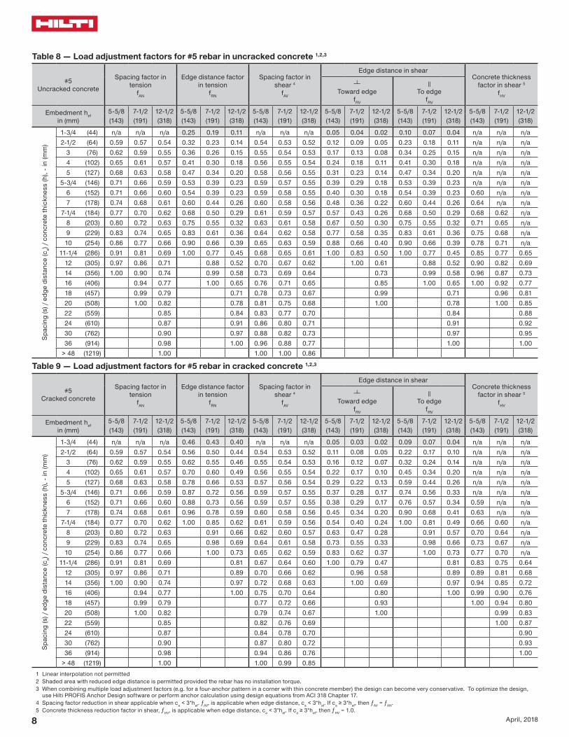

HIT-HY 100 Technical Supplement
9April 2018
Table 10 mdash Load adjustment factors for 6 rebar in uncracked concrete 123
6Uncracked concrete
Spacing factor in tension
fAN
Edge distance factor in tension
fRN
Spacing factor in shear 4
fAV
Edge distance in shearConcrete thickness
factor in shear 5
fHV
Toward edge
fRV
To edge
fRV
Embedment hefin (mm)
6-34 9 15 6-34 9 15 6-34 9 15 6-34 9 15 6-34 9 15 6-34 9 15 (171) (229) (381) (171) (229) (381) (171) (229) (381) (171) (229) (381) (171) (229) (381) (171) (229) (381)
Spac
ing
(s)
edg
e di
stan
ce (c
a) c
oncr
ete
thic
knes
s (h
) - i
n (m
m)
1-34 (44) na na na 024 018 010 na na na 004 003 002 007 006 003 na na na3-34 (95) 059 057 054 032 023 014 054 053 052 012 009 005 023 017 010 na na na
4 (102) 060 057 054 033 024 014 054 053 052 013 010 006 026 019 012 na na na5 (127) 062 059 056 037 027 016 055 054 053 018 013 008 036 027 016 na na na6 (152) 065 061 057 041 030 018 056 055 054 023 018 011 041 030 018 na na na8 (203) 070 065 059 051 037 022 058 057 055 036 027 016 051 037 022 na na na
8-12 (216) 071 066 059 053 039 023 059 057 055 040 030 018 053 039 023 060 na na10 (254) 075 069 061 063 046 027 061 059 056 051 038 023 063 046 027 065 na na
10-34 (273) 077 070 062 068 050 029 061 059 057 056 042 025 068 050 029 067 061 na12 (305) 080 072 063 075 055 032 063 060 057 066 050 030 075 055 032 071 065 na14 (356) 085 076 066 088 065 038 065 062 059 084 063 038 088 065 038 077 070 na16 (406) 090 080 068 100 074 043 067 064 060 100 077 046 100 074 043 082 075 na
16-34 (425) 091 081 069 077 045 068 065 060 082 049 077 045 084 076 06418 (457) 094 083 070 083 049 069 066 061 091 055 083 049 087 079 06720 (508) 099 087 072 092 054 071 067 062 100 064 092 054 092 084 07022 (559) 100 091 074 100 059 073 069 064 074 100 059 096 088 07424 (610) 094 077 065 075 071 065 085 065 100 092 07726 (660) 098 079 070 077 073 066 095 070 095 08028 (711) 100 081 076 080 074 067 100 076 099 08330 (762) 083 081 082 076 069 081 100 08636 (914) 090 097 088 081 072 097 095
gt 48 (1219) 100 100 100 092 080 100 100
Table 11 mdash Load adjustment factors for 6 rebar in cracked concrete 123
6Cracked concrete
Spacing factor in tension
fAN
Edge distance factor in tension
fRN
Spacing factor in shear 4
fAV
Edge distance in shearConcrete thickness
factor in shear 5
fHV
Toward edge
fRV
To edge
fRV
Embedment hefin (mm)
6-34 9 15 6-34 9 15 6-34 9 15 6-34 9 15 6-34 9 15 6-34 9 15 (171) (229) (381) (171) (229) (381) (171) (229) (381) (171) (229) (381) (171) (229) (381) (171) (229) (381)
Spac
ing
(s)
edg
e di
stan
ce (c
a) c
oncr
ete
thic
knes
s (h
) - i
n (m
m)
1-34 (44) na na na 044 042 039 na na na 003 003 002 007 005 003 na na na3-34 (95) 059 057 054 056 050 044 054 053 052 011 008 005 022 016 010 na na na
4 (102) 060 057 054 057 051 044 054 053 052 012 009 005 024 018 011 na na na5 (127) 062 059 056 063 056 047 055 054 053 017 012 007 034 025 015 na na na6 (152) 065 061 057 070 060 049 056 055 054 022 016 010 044 033 020 na na na8 (203) 070 065 059 084 070 055 058 057 055 034 025 015 068 051 030 na na na
8-12 (216) 071 066 059 088 072 056 059 057 055 037 028 017 075 055 033 059 na na10 (254) 075 069 061 099 080 060 060 058 056 048 035 021 095 071 042 064 na na
10-34 (273) 077 070 062 100 084 062 061 059 056 053 039 024 100 079 047 066 060 na12 (305) 080 072 063 091 066 062 060 057 063 046 028 091 056 070 063 na14 (356) 085 076 066 100 072 064 062 058 079 059 035 100 070 076 068 na16 (406) 090 080 068 078 066 063 059 097 071 043 078 081 073 na
16-34 (425) 091 081 069 081 067 064 060 100 077 046 081 083 075 06318 (457) 094 083 070 085 068 065 061 085 051 085 086 077 06520 (508) 099 087 072 091 070 067 062 100 060 091 090 082 06922 (559) 100 091 074 098 072 068 063 069 098 095 086 07224 (610) 094 077 100 074 070 064 079 100 099 089 07526 (660) 098 079 076 072 065 089 100 093 07828 (711) 100 081 079 073 067 099 097 08130 (762) 083 081 075 068 100 100 08436 (914) 090 087 080 071 092
gt 48 (1219) 100 099 090 078 1001 Linear interpolation not permitted2 Shaded area with reduced edge distance is permitted provided the rebar has no installation torque3 When combining multiple load adjustment factors (eg for a four-anchor pattern in a corner with thin concrete member) the design can become very conservative To optimize the design
use Hilti PROFIS Anchor Design software or perform anchor calculation using design equations from ACI 318 Chapter 174 Spacing factor reduction in shear applicable when ca lt 3hef ƒAV is applicable when edge distance ca lt 3hef If ca ge 3hef then ƒAV = ƒAN 5 Concrete thickness reduction factor in shear ƒHV is applicable when edge distance ca lt 3hef If ca ge 3hef then ƒHV = 10
10 April 2018
Table 12 mdash Load adjustment factors for 7 rebar in uncracked concrete 123
7Uncracked concrete
Spacing factor in tension
fAN
Edge distance factor in tension
fRN
Spacing factor in shear 4
fAV
Edge distance in shearConcrete thickness
factor in shear 5
fHV
Toward edge
fRV
To edge
fRV
Embedment hefin (mm)
7-78 10-12 17-12 7-78 10-12 17-12 7-78 10-12 17-12 7-78 10-12 17-12 7-78 10-12 17-12 7-78 10-12 17-12(200) (267) (445) (200) (267) (445) (200) (267) (445) (200) (267) (445) (200) (267) (445) (200) (267) (445)
Spac
ing
(s)
edg
e di
stan
ce (c
a) c
oncr
ete
thic
knes
s (h
) - i
n (m
m)
1-34 (44) na na na 023 017 010 na na na 003 002 001 005 004 002 na na na4-38 (111) 059 057 054 032 023 014 054 053 052 011 008 005 022 016 010 na na na
5 (127) 061 058 055 034 025 015 054 054 053 013 010 006 027 020 012 na na na6 (152) 063 060 056 037 028 016 055 054 053 017 013 008 035 026 016 na na na7 (178) 065 061 057 041 030 018 056 055 054 022 016 010 041 030 018 na na na8 (203) 067 063 058 045 033 019 057 056 054 027 020 012 045 033 019 na na na
9-78 (251) 071 066 059 053 039 023 059 057 055 037 028 017 053 039 023 059 na na10 (254) 071 066 060 054 040 023 059 057 055 038 028 017 054 040 023 059 na na12 (305) 075 069 061 065 048 028 060 059 056 049 037 022 065 048 028 065 na na
12-12 (318) 076 070 062 067 050 029 061 059 056 052 039 024 067 050 029 066 060 na14 (356) 080 072 063 075 055 033 062 060 057 062 046 028 075 055 033 070 063 na16 (406) 084 075 065 086 063 037 064 061 058 076 057 034 086 063 037 075 068 na18 (457) 088 079 067 097 071 042 066 063 059 091 068 041 097 071 042 079 072 na
19-12 (495) 091 081 069 100 077 045 067 064 060 100 076 046 100 077 045 082 075 06320 (508) 092 082 069 079 046 067 064 060 079 048 079 046 083 076 06422 (559) 097 085 071 087 051 069 066 061 092 055 087 051 087 079 06724 (610) 100 088 073 095 056 071 067 062 100 063 095 056 091 083 07026 (660) 091 075 100 060 073 069 063 071 100 060 095 086 07328 (711) 094 077 065 074 070 064 079 065 099 089 07530 (762) 098 079 070 076 071 065 087 070 100 093 07836 (914) 100 084 084 081 076 068 100 084 100 086
gt 48 (1219) 096 100 092 084 074 100 099
Table 13 mdash Load adjustment factors for 7 rebar in cracked concrete 123
7Cracked concrete
Spacing factor in tension
fAN
Edge distance factor in tension
fRN
Spacing factor in shear 4
fAV
Edge distance in shearConcrete thickness
factor in shear 5
fHV
Toward edge
fRV
To edge
fRV
Embedment hefin (mm)
7-78 10-12 17-12 7-78 10-12 17-12 7-78 10-12 17-12 7-78 10-12 17-12 7-78 10-12 17-12 7-78 10-12 17-12(200) (267) (445) (200) (267) (445) (200) (267) (445) (200) (267) (445) (200) (267) (445) (200) (267) (445)
Spac
ing
(s)
edg
e di
stan
ce (c
a) c
oncr
ete
thic
knes
s (h
) - i
n (m
m)
1-34 (44) na na na 043 041 038 na na na 003 002 001 006 005 003 na na na4-38 (111) 059 057 054 056 050 044 054 053 052 012 009 005 024 018 011 na na na
5 (127) 061 058 055 059 052 045 055 054 053 015 011 007 029 022 013 na na na6 (152) 063 060 056 064 056 047 056 055 053 019 014 009 038 029 017 na na na7 (178) 065 061 057 070 060 049 056 055 054 024 018 011 048 036 022 na na na8 (203) 067 063 058 076 064 052 057 056 054 029 022 013 059 044 026 na na na
9-78 (251) 071 066 059 087 072 056 059 058 055 040 030 018 081 060 036 060 na na10 (254) 071 066 060 088 073 056 059 058 055 041 031 018 082 062 037 061 na na12 (305) 075 069 061 100 082 061 061 059 056 054 041 024 100 081 049 066 na na
12-12 (318) 076 070 062 084 062 062 060 057 057 043 026 100 084 052 068 062 na14 (356) 080 072 063 091 066 063 061 058 068 051 031 091 061 072 065 na16 (406) 084 075 065 100 071 065 062 059 083 062 037 100 071 077 070 na18 (457) 088 079 067 076 067 064 060 099 074 045 076 081 074 na
19-12 (495) 091 081 069 080 068 065 061 100 084 050 080 085 077 06520 (508) 092 082 069 082 068 065 061 087 052 082 086 078 06622 (559) 097 085 071 087 070 067 062 100 060 087 090 082 06924 (610) 100 088 073 093 072 068 063 069 093 094 085 07226 (660) 091 075 099 074 070 064 078 099 098 089 07528 (711) 094 077 100 076 071 065 087 100 100 092 07830 (762) 098 079 078 073 066 096 096 08136 (914) 100 084 083 077 069 100 100 088
gt 48 (1219) 096 094 086 076 1001 Linear interpolation not permitted2 Shaded area with reduced edge distance is permitted provided the rebar has no installation torque3 When combining multiple load adjustment factors (eg for a four-anchor pattern in a corner with thin concrete member) the design can become very conservative To optimize the design
use Hilti PROFIS Anchor Design software or perform anchor calculation using design equations from ACI 318 Chapter 174 Spacing factor reduction in shear applicable when ca lt 3hef ƒAV is applicable when edge distance ca lt 3hef If ca ge 3hef then ƒAV = ƒAN 5 Concrete thickness reduction factor in shear ƒHV is applicable when edge distance ca lt 3hef If ca ge 3hef then ƒHV = 10
HIT-HY 100 Technical Supplement
11April 2018
Table 14 mdash Load adjustment factors for 8 rebar in uncracked concrete 123
8Uncracked concrete
Spacing factor in tension
fAN
Edge distance factor in tension
fRN
Spacing factor in shear 4
fAV
Edge distance in shearConcrete thickness
factor in shear 5
fHV
Toward edge
fRV
To edge
fRV
Embedment hefin (mm)
9 12 20 9 12 20 9 12 20 9 12 20 9 12 20 9 12 20 (229) (305) (508) (229) (305) (508) (229) (305) (508) (229) (305) (508) (229) (305) (508) (229) (305) (508)
Spac
ing
(s)
edg
e di
stan
ce (c
a) c
oncr
ete
thic
knes
s (h
) - i
n (m
m)
1-34 (44) na na na 023 017 010 na na na 002 002 001 005 003 002 na na na5 (127) 059 057 054 032 023 014 054 053 052 011 008 005 022 015 009 na na na6 (152) 061 058 055 035 026 015 055 054 053 014 010 006 029 020 012 na na na7 (178) 063 060 056 038 028 016 055 054 053 018 013 008 036 025 015 na na na8 (203) 065 061 057 041 030 018 056 055 053 022 015 009 041 030 018 na na na9 (229) 067 063 058 045 033 019 057 055 054 026 018 011 045 033 019 na na na10 (254) 069 064 058 048 036 021 058 056 054 031 022 013 048 036 021 na na na
11-14 (286) 071 066 059 053 039 023 059 057 055 037 026 016 053 039 023 058 na na12 (305) 072 067 060 057 042 024 059 057 055 040 028 017 057 042 024 060 na na14 (356) 076 069 062 066 049 029 061 058 056 051 036 022 066 049 029 065 na na
14-14 (362) 076 070 062 067 050 029 061 059 056 052 037 022 067 050 029 066 059 na16 (406) 080 072 063 076 056 033 062 060 057 062 044 026 076 056 033 070 062 na18 (457) 083 075 065 085 063 037 064 061 058 074 052 031 085 063 037 074 066 na20 (508) 087 078 067 095 070 041 065 062 059 087 061 037 095 070 041 078 069 na22 (559) 091 081 068 100 076 045 067 063 059 100 071 042 100 076 045 082 073 na
22-14 (565) 091 081 069 077 045 067 063 060 072 043 077 045 082 073 06224 (610) 094 083 070 083 049 068 064 060 081 048 083 049 085 076 06426 (660) 098 086 072 090 053 070 066 061 091 054 090 053 089 079 06728 (711) 100 089 073 097 057 071 067 062 100 061 097 057 092 082 06930 (762) 092 075 100 061 073 068 063 068 100 061 095 085 07236 (914) 100 080 073 077 072 065 089 073 100 093 078
gt 48 (1219) 090 098 086 079 071 100 098 100 091
Table 15 mdash Load adjustment factors for 8 rebar in cracked concrete 123
8Cracked concrete
Spacing factor in tension
fAN
Edge distance factor in tension
fRN
Spacing factor in shear 4
fAV
Edge distance in shearConcrete thickness
factor in shear 5
fHV
Toward edge
fRV
To edge
fRV
Embedment hefin (mm)
9 12 20 9 12 20 9 12 20 9 12 20 9 12 20 9 12 20 (229) (305) (508) (229) (305) (508) (229) (305) (508) (229) (305) (508) (229) (305) (508) (229) (305) (508)
Spac
ing
(s)
edg
e di
stan
ce (c
a) c
oncr
ete
thic
knes
s (h
) - i
n (m
m)
1-34 (44) na na na 042 040 038 na na na 002 002 001 005 003 002 na na na5 (127) 059 057 054 056 050 044 054 053 052 011 008 005 022 017 010 na na na6 (152) 061 058 055 060 053 046 055 054 053 015 011 007 029 022 013 na na na7 (178) 063 060 056 065 057 047 055 054 053 018 014 008 037 028 017 na na na8 (203) 065 061 057 070 060 049 056 055 054 023 017 010 045 034 020 na na na9 (229) 067 063 058 075 064 051 057 056 054 027 020 012 054 040 024 na na na10 (254) 069 064 058 080 067 053 058 056 055 031 024 014 063 047 028 na na na
11-14 (286) 071 066 059 087 072 056 059 057 055 038 028 017 075 056 034 059 na na12 (305) 072 067 060 091 075 057 059 058 055 041 031 019 083 062 037 061 na na14 (356) 076 069 062 100 083 062 061 059 056 052 039 023 100 078 047 066 na na
14-14 (362) 076 070 062 084 062 061 059 056 054 040 024 080 048 066 060 na16 (406) 080 072 063 091 066 062 060 057 064 048 029 091 057 070 064 na18 (457) 083 075 065 100 070 064 061 058 076 057 034 100 068 075 068 na20 (508) 087 078 067 075 065 063 059 089 067 040 075 079 071 na22 (559) 091 081 068 080 067 064 060 100 077 046 080 082 075 na
22-14 (565) 091 081 069 080 067 064 060 078 047 080 083 075 06324 (610) 094 083 070 085 069 065 061 088 053 085 086 078 06626 (660) 098 086 072 090 070 067 062 099 059 090 090 081 06928 (711) 100 089 073 095 072 068 063 100 066 095 093 084 07130 (762) 092 075 100 073 069 064 074 100 096 087 07436 (914) 100 080 078 073 066 097 100 096 081
gt 48 (1219) 090 087 081 072 100 100 0931 Linear interpolation not permitted2 Shaded area with reduced edge distance is permitted provided the rebar has no installation torque3 When combining multiple load adjustment factors (eg for a four-anchor pattern in a corner with thin concrete member) the design can become very conservative To optimize the design
use Hilti PROFIS Anchor Design software or perform anchor calculation using design equations from ACI 318 Chapter 174 Spacing factor reduction in shear applicable when ca lt 3hef ƒAV is applicable when edge distance ca lt 3hef If ca ge 3hef then ƒAV = ƒAN 5 Concrete thickness reduction factor in shear ƒHV is applicable when edge distance ca lt 3hef If ca ge 3hef then ƒHV = 10
12 April 2018
Table 16 mdash Load adjustment factors for 9 rebar in uncracked concrete 123
9Uncracked concrete
Spacing factor in tension
fAN
Edge distance factor in tension
fRN
Spacing factor in shear 4
fAV
Edge distance in shearConcrete thickness
factor in shear 5
fHV
Toward edge
fRV
To edge
fRV
Embedment hefin (mm)
10-18 13-12 22-12 10-18 13-12 22-12 10-18 13-12 22-12 10-18 13-12 22-12 10-18 13-12 22-12 10-18 13-12 22-12(257) (343) (572) (257) (343) (572) (257) (343) (572) (257) (343) (572) (257) (343) (572) (257) (343) (572)
Spac
ing
(s)
edg
e di
stan
ce (c
a) c
oncr
ete
thic
knes
s (h
) - i
n (m
m)
1-34 (44) na na na 022 016 010 na na na 002 001 001 004 003 002 na na na5-58 (143) 059 057 054 032 024 014 054 053 052 011 008 005 022 015 009 na na na
6 (152) 060 057 054 033 024 014 054 053 052 012 008 005 024 017 010 na na na7 (178) 062 059 055 036 026 015 055 054 053 015 011 006 030 021 013 na na na8 (203) 063 060 056 039 029 017 055 054 053 018 013 008 037 026 016 na na na9 (229) 065 061 057 042 031 018 056 055 053 022 016 009 042 031 018 na na na10 (254) 066 062 057 045 033 019 057 055 054 026 018 011 045 033 019 na na na12 (305) 070 065 059 052 038 022 058 056 055 034 024 014 052 038 022 na na na
12-78 (327) 071 066 060 056 041 024 059 057 055 038 027 016 056 041 024 059 na na14 (356) 073 067 060 061 045 026 059 057 055 043 030 018 061 045 026 061 na na16 (406) 076 070 062 069 051 030 061 059 056 052 037 022 069 051 030 066 na na
16-14 (413) 077 070 062 070 052 030 061 059 056 053 038 023 070 052 030 066 059 na18 (457) 080 072 063 078 057 033 062 060 057 062 044 026 078 057 033 070 062 na20 (508) 083 075 065 087 064 037 063 061 058 073 051 031 087 064 037 073 065 na22 (559) 086 077 066 095 070 041 065 062 058 084 059 036 095 070 041 077 069 na24 (610) 090 080 068 100 076 045 066 063 059 096 067 040 100 076 045 080 072 na
25-14 (641) 092 081 069 080 047 067 063 060 100 073 044 080 047 083 073 06226 (660) 093 082 069 083 048 068 064 060 076 046 083 048 084 075 06328 (711) 096 085 071 089 052 069 065 061 085 051 089 052 087 077 06530 (762) 099 087 072 095 056 070 066 061 094 057 095 056 090 080 06836 (914) 100 094 077 100 067 074 069 064 100 074 100 067 099 088 074
gt 48 (1219) 100 086 100 089 082 076 068 100 089 100 100 085
Table 17 mdash Load adjustment factors for 9 rebar in cracked concrete 123
9Cracked concrete
Spacing factor in tension
fAN
Edge distance factor in tension
fRN
Spacing factor in shear 4
fAV
Edge distance in shearConcrete thickness
factor in shear 5
fHV
Toward edge
fRV
To edge
fRV
Embedment hefin (mm)
10-18 13-12 22-12 10-18 13-12 22-12 10-18 13-12 22-12 10-18 13-12 22-12 10-18 13-12 22-12 10-18 13-12 22-12(257) (343) (572) (257) (343) (572) (257) (343) (572) (257) (343) (572) (257) (343) (572) (257) (343) (572)
Spac
ing
(s)
edg
e di
stan
ce (c
a) c
oncr
ete
thic
knes
s (h
) - i
n (m
m)
1-34 (44) na na na 041 039 038 na na na 002 001 001 004 003 002 na na na5-58 (143) 059 057 054 056 050 044 054 053 052 011 008 005 022 016 009 na na na
6 (152) 060 057 054 057 051 044 054 053 052 012 009 005 024 017 010 na na na7 (178) 062 059 055 061 054 046 055 054 053 015 011 007 030 022 013 na na na8 (203) 063 060 056 065 057 048 055 054 053 019 013 008 037 027 016 na na na9 (229) 065 061 057 070 060 049 056 055 053 022 016 010 044 032 019 na na na10 (254) 066 062 057 074 063 051 057 055 054 026 019 011 052 037 022 na na na12 (305) 070 065 059 084 070 055 058 057 055 034 025 015 068 049 029 na na na
12-78 (327) 071 066 060 088 073 056 059 057 055 038 027 016 076 054 033 059 na na14 (356) 073 067 060 094 077 058 060 058 055 043 031 019 086 062 037 062 na na16 (406) 076 070 062 100 084 062 061 059 056 053 038 023 100 075 045 066 na na
16-14 (413) 077 070 062 085 063 061 059 056 054 039 023 077 046 066 059 na18 (457) 080 072 063 091 066 062 060 057 063 045 027 090 054 070 063 na20 (508) 083 075 065 099 070 064 061 058 073 053 032 099 063 074 066 na22 (559) 086 077 066 100 074 065 062 059 085 061 036 100 073 077 069 na24 (610) 090 080 068 078 066 063 059 097 069 042 078 081 072 na
25-14 (641) 092 081 069 081 067 064 060 100 075 045 081 083 074 06326 (660) 093 082 069 082 068 064 060 078 047 082 084 075 06328 (711) 096 085 071 087 069 065 061 087 052 087 087 078 06630 (762) 099 087 072 091 070 066 062 097 058 091 090 081 06836 (914) 100 094 077 100 074 070 064 100 076 100 099 088 075
gt 48 (1219) 100 086 083 076 069 100 100 100 0861 Linear interpolation not permitted2 Shaded area with reduced edge distance is permitted provided the rebar has no installation torque3 When combining multiple load adjustment factors (eg for a four-anchor pattern in a corner with thin concrete member) the design can become very conservative To optimize the design
use Hilti PROFIS Anchor Design software or perform anchor calculation using design equations from ACI 318 Chapter 174 Spacing factor reduction in shear applicable when ca lt 3hef ƒAV is applicable when edge distance ca lt 3hef If ca ge 3hef then ƒAV = ƒAN 5 Concrete thickness reduction factor in shear ƒHV is applicable when edge distance ca lt 3hef If ca ge 3hef then ƒHV = 10
HIT-HY 100 Technical Supplement
13April 2018
Table 18 mdash Load adjustment factors for 10 rebar in uncracked concrete 123
10Uncracked concrete
Spacing factor in tension
fAN
Edge distance factor in tension
fRN
Spacing factor in shear 4
fAV
Edge distance in shearConcrete thickness
factor in shear 5
fHV
Toward edge
fRV
To edge
fRV
Embedment hefin (mm)
11-14 15 25 11-14 15 25 11-14 15 25 11-14 15 25 11-14 15 25 11-14 15 25 (286) (381) (635) (286) (381) (635) (286) (381) (635) (286) (381) (635) (286) (381) (635) (286) (381) (635)
Spac
ing
(s)
edg
e di
stan
ce (c
a) c
oncr
ete
thic
knes
s (h
) - i
n (m
m) 1-34 (44) na na na 022 016 009 na na na 002 001 001 003 002 001 na na na
6-14 (159) 059 057 054 033 024 014 054 053 052 011 008 005 022 016 010 na na na7 (178) 060 058 055 035 025 015 054 053 052 013 010 006 026 019 012 na na na8 (203) 062 059 055 037 027 016 055 054 053 016 012 007 031 023 014 na na na9 (229) 063 060 056 040 030 017 055 054 053 019 014 008 038 028 017 na na na10 (254) 065 061 057 043 032 019 056 055 054 022 016 010 043 032 019 na na na11 (279) 066 062 057 046 034 020 057 055 054 025 019 011 046 034 020 na na na12 (305) 068 063 058 049 036 021 057 056 054 029 022 013 049 036 021 na na na14 (356) 071 066 059 057 042 024 059 057 055 036 027 016 057 042 024 na na na
14-14 (362) 071 066 060 058 043 025 059 057 055 037 028 017 058 043 025 059 na na16 (406) 074 068 061 065 048 028 060 058 056 045 033 020 065 048 028 062 na na17 (432) 075 069 061 069 051 030 060 058 056 049 036 022 069 051 030 064 na na18 (457) 077 070 062 073 054 031 061 059 056 053 040 024 073 054 031 066 060 na20 (508) 080 072 063 081 060 035 062 060 057 062 046 028 081 060 035 070 063 na22 (559) 083 074 065 089 066 038 063 061 058 072 054 032 089 066 038 073 066 na24 (610) 086 077 066 098 072 042 065 062 059 082 061 037 098 072 042 076 069 na26 (660) 089 079 067 100 078 045 066 063 059 092 069 041 100 078 045 079 072 na28 (711) 091 081 069 084 049 067 064 060 100 077 046 084 049 082 075 06330 (762) 094 083 070 090 052 068 065 061 085 051 090 052 085 077 06536 (914) 100 090 074 100 063 072 068 063 100 067 100 063 094 085 072
gt 48 (1219) 100 082 084 079 074 067 100 084 100 098 083
Table 19 mdash Load adjustment factors for 10 rebar in cracked concrete 123
10Cracked concrete
Spacing factor in tension
fAN
Edge distance factor in tension
fRN
Spacing factor in shear 4
fAV
Edge distance in shearConcrete thickness
factor in shear 5
fHV
Toward edge
fRV
To edge
fRV
Embedment hefin (mm)
11-14 15 25 11-14 15 25 11-14 15 25 11-14 15 25 11-14 15 25 11-14 15 25 (286) (381) (635) (286) (381) (635) (286) (381) (635) (286) (381) (635) (286) (381) (635) (286) (381) (635)
Spac
ing
(s)
edg
e di
stan
ce (c
a) c
oncr
ete
thic
knes
s (h
) - i
n (m
m) 1-34 (44) na na na 040 039 037 na na na 002 001 001 003 002 001 na na na
6-14 (159) 059 057 054 056 050 044 054 053 052 011 007 004 022 015 009 na na na7 (178) 060 058 055 058 052 045 054 053 052 013 009 005 026 018 011 na na na8 (203) 062 059 055 062 055 046 055 054 053 016 011 006 032 022 013 na na na9 (229) 063 060 056 066 057 048 055 054 053 019 013 008 038 026 015 na na na10 (254) 065 061 057 070 060 049 056 055 053 022 015 009 044 030 018 na na na11 (279) 066 062 057 074 063 051 057 055 054 026 017 010 051 035 021 na na na12 (305) 068 063 058 078 066 053 057 056 054 029 020 012 058 040 024 na na na14 (356) 071 066 059 087 072 056 059 057 055 037 025 015 073 050 030 na na na
14-14 (362) 071 066 060 088 073 056 059 057 055 038 026 015 075 051 031 059 na na16 (406) 074 068 061 096 078 059 060 058 055 045 031 018 090 061 037 063 na na17 (432) 075 069 061 100 081 061 060 058 056 049 033 020 098 067 040 064 na na18 (457) 077 070 062 085 062 061 059 056 054 036 022 100 073 044 066 058 na20 (508) 080 072 063 091 066 062 059 057 063 043 026 085 051 070 061 na22 (559) 083 074 065 098 069 063 060 057 072 049 030 098 059 073 064 na24 (610) 086 077 066 100 073 065 061 058 082 056 034 100 067 077 067 na26 (660) 089 079 067 077 066 062 059 093 063 038 076 080 070 na28 (711) 091 081 069 081 067 063 059 100 071 042 081 083 073 06130 (762) 094 083 070 085 068 064 060 078 047 085 086 075 06436 (914) 100 090 074 097 072 067 062 100 062 097 094 082 070
gt 48 (1219) 100 082 100 079 073 066 095 100 100 095 0801 Linear interpolation not permitted2 Shaded area with reduced edge distance is permitted provided the rebar has no installation torque3 When combining multiple load adjustment factors (eg for a four-anchor pattern in a corner with thin concrete member) the design can become very conservative To optimize the design
use Hilti PROFIS Anchor Design software or perform anchor calculation using design equations from ACI 318 Chapter 174 Spacing factor reduction in shear applicable when ca lt 3hef ƒAV is applicable when edge distance ca lt 3hef If ca ge 3hef then ƒAV = ƒAN 5 Concrete thickness reduction factor in shear ƒHV is applicable when edge distance ca lt 3hef If ca ge 3hef then ƒHV = 10
14 April 2018
Hilti HIT-HY 100 adhesive with Hilti HAS threaded rod
HIT-VHAS
Hilti HAS HIT-V threaded rod installation conditions
Perm
issi
ble
Bas
e M
ater
ials
Uncracked concrete
DryConcrete
Perm
issi
ble
Dril
ling
Met
hod
Hammer Drilling with Carbide Tipped
Drill Bit
Cracked concrete
Water Saturated Concrete
Hollow Drill Bit
Hilti HASHIT-V threaded rod installation specifications
Nominal Rod
Diameter
Drill Bit Diameter
Embedment Depth Range
Maximum Installation
Torque
Minimum Base Material
Thickness
din (mm)
d0in
hefin (mm)
Tmaxft-lb (Nm)
hminin (mm)
38716
2-38 ndash 7-12 15hef + 1-14 (hef + 30)
(95) (60 ndash 191) (20)12
916 2-34 ndash 10 30
(127) (70 ndash 254) (41)58
343-18 ndash 12-12 60
hef + 2d0
(159) (79 ndash 318) (81)34
783-12 ndash 15 100
(191) (89 ndash 381) (136)78
13-12 ndash 17-12 125
(222) (89 ndash 445) (169)1
1-184 ndash 20 150
(254) (102 ndash 508) (203)1-14
1-385 ndash 25 200
(318) (127 ndash 635) (271)
min
max
df HASHIT-V 38 12 58 34 78 1 1-14
df1 12 58 1316 1516 1-18 1-14 1-12
df2 716 916 1116 1316 1516 1-18 1-38 Use two washers
HIT-HY 100 Technical Supplement
15April 2018
Table 20 mdash Hilti HIT-HY 100 adhesive design strength with concrete bond failure for threaded rod in uncracked concrete 12345678
Nominal anchor
diameterin
Effective embedment
in (mm)
Tension mdash ϕNn Shear mdash ϕVn
f´c = 2500 psi(172 Mpa)
lb (kN)
f´c = 3000 psi(207 Mpa)
lb (kN)
f´c = 4000 psi(276 Mpa)
lb (kN)
f´c = 6000 psi(414 Mpa)
lb (kN)
f´c = 2500 psi(172 Mpa)
lb (kN)
f´c = 3000 psi(207 Mpa)
lb (kN)
f´c = 4000 psi(276 Mpa)
lb (kN)
f´c = 6000 psi(414 Mpa)
lb (kN)
38
2-38 2710 2760 2840 2960 2920 2970 3060 3185(60) (121) (123) (126) (132) (130) (132) (136) (142)
3-38 3850 3920 4035 4205 8295 8445 8695 9055(86) (171) (174) (179) (187) (369) (376) (387) (403)
4-12 5135 5230 5380 5605 11060 11260 11590 12070(114) (228) (233) (239) (249) (492) (501) (516) (537)7-12 8555 8715 8970 9340 18430 18770 19320 20120(191) (381) (388) (399) (415) (820) (835) (859) (895)
12
2-34 3555 3895 4385 4565 7660 8395 9445 9835(70) (158) (173) (195) (203) (341) (373) (420) (437)
4-12 6845 6970 7175 7470 14745 15015 15455 16095(114) (304) (310) (319) (332) (656) (668) (687) (716)
6 9130 9295 9565 9965 19660 20020 20605 21460(152) (406) (413) (425) (443) (875) (891) (917) (955)10 15215 15495 15945 16605 32765 33370 34345 35765
(254) (677) (689) (709) (739) (1457) (1484) (1528) (1591)
58
3-18 4310 4720 5450 6485 9280 10165 11740 13970(79) (192) (210) (242) (288) (413) (452) (522) (621)
5-58 10405 10895 11210 11675 22415 23465 24150 25145(143) (463) (485) (499) (519) (997) (1044) (1074) (1119)7-12 14260 14525 14950 15565 30720 31285 32195 33530(191) (634) (646) (665) (692) (1366) (1392) (1432) (1491)
12-12 23770 24210 24915 25945 51200 52140 53660 55880(318) (1057) (1077) (1108) (1154) (2277) (2319) (2387) (2486)
34
3-12 5105 5595 6460 7910 11000 12050 13915 17040(89) (227) (249) (287) (352) (489) (536) (619) (758)
6-34 13680 14985 16145 16815 29460 32275 34775 36210(171) (609) (667) (718) (748) (1310) (1436) (1547) (1611)
9 20540 20915 21525 22415 44235 45050 46365 48280(229) (914) (930) (957) (997) (1968) (2004) (2062) (2148)
15 34230 34860 35875 37360 73725 75080 77275 80470(381) (1523) (1551) (1596) (1662) (3279) (3340) (3437) (3579)
78
3-12 5105 5595 6460 7910 11000 12050 13915 17040(89) (227) (249) (287) (352) (489) (536) (619) (758)7-78 17235 18885 20500 21350 37125 40670 44155 45980(200) (767) (840) (912) (950) (1651) (1809) (1964) (2045)
10-12 26080 26560 27335 28465 56170 57200 58870 61305(267) (1160) (1181) (1216) (1266) (2499) (2544) (2619) (2727)17-12 43465 44265 45555 47440 93615 95335 98120 102180(445) (1933) (1969) (2026) (2110) (4164) (4241) (4365) (4545)
1
4 6240 6835 7895 9665 13440 14725 17000 20820(102) (278) (304) (351) (430) (598) (655) (756) (926)
9 21060 23070 24465 25475 45360 49690 52690 54870(229) (937) (1026) (1088) (1133) (2018) (2210) (2344) (2441)
12 31120 31695 32620 33970 67030 68260 70255 73160(305) (1384) (1410) (1451) (1511) (2982) (3036) (3125) (3254)
20 51870 52820 54365 56615 111715 113770 117090 121935(508) (2307) (2350) (2418) (2518) (4969) (5061) (5208) (5424)
1-14
5 8720 9555 11030 12140 18785 20575 23760 29100(127) (388) (425) (491) (540) (836) (915) (1057) (1294)11-14 25025 25490 26230 27315 63395 64880 66770 69535(286) (1113) (1134) (1167) (1215) (2820) (2886) (2970) (3093)
15 33370 33985 34975 36425 84940 86505 89030 92710(381) (1484) (1512) (1556) (1620) (3778) (3848) (3960) (4124)25 55615 56640 58290 60705 141570 144175 148380 154520
(635) (2474) (2519) (2593) (2700) (6297) (6413) (6600) (6873)1 See Section 318 (2017 PTG) for explanation on development of load values2 See Section 3186 (2017 PTG) to convert design strength value to ASD value3 Linear interpolation between embedment depths and concrete compressive strengths is not permitted4 Load values are for a single anchor with no spacing edge distance or concrete thickness factors Apply spacing edge distance and concrete thickness factors in tables 23-35 as
necessary Compare to the steel values in table 22 The lesser of the values is to be used for the design5 Data is for temperature range A Max short term temperature = 130degF (55degC) max long term temperature = 110degF (43degC) For temperature range B Max short term temperature = 176degF (80degC) max long term temperature = 110degF (43degC) multiply above value by 092 For temperature range C Max short term temperature = 210degF (99degC) max long term temperature = 162degF (72degC) multiply above value by 071 Short term elevated concrete temperatures are those that occur over brief intervals eg as a result of diurnal cycling Long term concrete temperatures are roughly constant over significant periods of time6 Tabular values are for dry concrete conditions For water saturated concrete multiply design strength (factored resistance) by 0857 Tabular values are for short term loads only For sustained loads including overhead use see Section 3188 (2017 PTG)8 Tabular values are for normal-weight concrete only For lightweight concrete multiply design strength by λa as follows For sand-lightweight λa = 051 For all-lightweight λa = 045
16 April 2018
Table 21 mdash Hilti HIT-HY 100 adhesive design strength with concrete bond failure for threaded rod in cracked concrete 123456789
Nominal anchor
diameterin
Effective embedment
in (mm)
Tension mdash ϕNn Shear mdash ϕVn
f´c = 2500 psi(172 Mpa)
lb (kN)
f´c = 3000 psi(207 Mpa)
lb (kN)
f´c = 4000 psi(276 Mpa)
lb (kN)
f´c = 6000 psi(414 Mpa)
lb (kN)
f´c = 2500 psi(172 Mpa)
lb (kN)
f´c = 3000 psi(207 Mpa)
lb (kN)
f´c = 4000 psi(276 Mpa)
lb (kN)
f´c = 6000 psi(414 Mpa)
lb (kN)
38
2-38 1120 1140 1170 1220 1205 1225 1260 1315(60) (50) (51) (52) (54) (54) (54) (56) (58)
3-38 1590 1620 1665 1735 3425 3485 3590 3735(86) (71) (72) (74) (77) (152) (155) (160) (166)
4-12 2120 2160 2220 2315 4565 4650 4785 4980(114) (94) (96) (99) (103) (203) (207) (213) (222)7-12 3530 3595 3700 3855 7610 7750 7975 8305(191) (157) (160) (165) (171) (339) (345) (355) (369)
12
2-34 1880 1915 1970 2055 4050 4125 4245 4425(70) (84) (85) (88) (91) (180) (183) (189) (197)
4-12 3080 3135 3225 3360 6630 6750 6950 7235(114) (137) (139) (143) (149) (295) (300) (309) (322)
6 4105 4180 4300 4480 8840 9005 9265 9650(152) (183) (186) (191) (199) (393) (401) (412) (429)10 6840 6965 7170 7465 14735 15005 15445 16080
(254) (304) (310) (319) (332) (655) (667) (687) (715)
58
3-18 2890 2945 3030 3155 6230 6345 6530 6800(79) (129) (131) (135) (140) (277) (282) (290) (302)
5-58 5205 5300 5455 5680 11210 11415 11750 12235(143) (232) (236) (243) (253) (499) (508) (523) (544)7-12 6940 7065 7275 7575 14945 15220 15665 16315(191) (309) (314) (324) (337) (665) (677) (697) (726)
12-12 11565 11780 12125 12625 24910 25370 26110 27190(318) (514) (524) (539) (562) (1108) (1129) (1161) (1209)
34
3-12 3620 3965 4355 4535 7790 8535 9380 9765(89) (161) (176) (194) (202) (347) (380) (417) (434)
6-34 8010 8160 8395 8745 17255 17575 18085 18835(171) (356) (363) (373) (389) (768) (782) (804) (838)
9 10680 10880 11195 11660 23010 23430 24115 25115(229) (475) (484) (498) (519) (1024) (1042) (1073) (1117)
15 17805 18130 18660 19435 38345 39055 40190 41855(381) (792) (806) (830) (865) (1706) (1737) (1788) (1862)
78
3-12 3620 3965 4575 5325 7790 8535 9855 11470(89) (161) (176) (204) (237) (347) (380) (438) (510)7-78 10975 11175 11505 11980 23640 24075 24775 25800(200) (488) (497) (512) (533) (1052) (1071) (1102) (1148)
10-12 14635 14905 15340 15975 31520 32100 33035 34405(267) (651) (663) (682) (711) (1402) (1428) (1469) (1530)17-12 24390 24840 25565 26620 52530 53500 55060 57340(445) (1085) (1105) (1137) (1184) (2337) (2380) (2449) (2551)
1
4 4420 4840 5590 6845 9520 10430 12040 14750(102) (197) (215) (249) (304) (423) (464) (536) (656)
9 14520 14785 15220 15845 31270 31845 32775 34135(229) (646) (658) (677) (705) (1391) (1417) (1458) (1518)
12 19360 19715 20290 21130 41695 42460 43700 45510(305) (861) (877) (903) (940) (1855) (1889) (1944) (2024)
32265 32860 33815 35215 69490 70770 72835 75850(508) (1435) (1462) (1504) (1566) (3091) (3148) (3240) (3374)
1 See Section 318 (2017 PTG) for explanation on development of load values2 See Section 3186 (2017 PTG) to convert design strength value to ASD value3 Linear interpolation between embedment depths and concrete compressive strengths is not permitted4 Load values are for a single anchor with no spacing edge distance or concrete thickness factors Apply spacing edge distance and concrete thickness factors in tables 23-35 as
necessary Compare to the steel values in table 22 The lesser of the values is to be used for the design5 Data is for temperature range A Max short term temperature = 130degF (55degC) max long term temperature = 110degF (43degC) For temperature range B Max short term temperature = 176degF (80degC) max long term temperature = 110degF (43degC) multiply above value by 092 For temperature range C Max short term temperature = 210degF (99degC) max long term temperature = 162degF (72degC) multiply above value by 071 Short term elevated concrete temperatures are those that occur over brief intervals eg as a result of diurnal cycling Long term concrete temperatures are roughly constant over significant periods of time6 Tabular values are for dry concrete conditions For water saturated concrete multiply design strength (factored resistance) by 0857 Tabular values are for short term loads only For sustained loads including overhead use see Section 3188 (2017 PTG)8 Tabular values are for normal-weight concrete only For lightweight concrete multiply design strength by λa as follows For sand-lightweight λa = 051 For all-lightweight λa = 045 9 Tabular values are for static loads only For seismic loads multiply cracked concrete tabular values in tension and shear by αseis = 075
HIT-HY 100 Technical Supplement
17April 2018
Table 22 mdash Steel design strength HAS and HIT-V anchor threaded rods for use with ACI 318-14 Ch 17
Nominal anchor
diameterin
HIT-VASTM A307 Grade A 4
HAS-EISO 898 Class 58 4
HAS-E-B and HAS-E-B HDGASTM A193 B7 and
ASTM F 1554 Gr 105 5
Tensile1
ϕNsalb (kN)
Shear2
ϕVsalb (kN)
Seismic Shear3
ϕVsaeqlb (kN)
Tensile1
ϕNsalb (kN)
Shear2
ϕVsalb (kN)
Seismic Shear3
ϕVsaeqlb (kN)
Tensile1
ϕNsalb (kN)
Shear2
ϕVsalb (kN)
Seismic Shear3
ϕVsaeqlb (kN)
38 3025 1675 1175 3655 2020 1415 7265 3780 2645(135) (75) (52) (163) (90) (63) (323) (168) (118)
12 5535 3065 2145 6690 3705 2595 13300 6915 4840(246) (136) (95) (295) (165) (115) (592) (308) (215)
58 8815 4880 3415 10650 5900 4130 21190 11020 7715(392) (216) (152) (474) (262) (184) (943) (490) (343)
34 13045 7225 5060 15765 8730 6110 31360 16305 11415(580) (321) (225) (701) (388) (272) (1395) (725) (508)
78 - - - 21755 12050 8435 43285 22505 15755- - - (968) (536) (375) (1925) (1001) (701)
123620 13085 9160 28540 15805 11065 56785 29525 20670(1051) (582) (407) (1270) (703) (492) (2526) (1313) (919)
1-14- - - 45670 25295 17705 90850 47240 33070- - - (2003) (1125) (788) (4041) (2101) (1471)
1 Tensile = ϕ AseN futa as noted in ACI 318-14 174122 Shear = ϕ 060 AseV futa as noted in ACI 318-14 17512b3 Seismic Shear = αVseis ϕVsa Reduction factor for seismic shear only See ACI 318 for additional information on seismic applications 4 HIT-V and HAS-E threaded rods are considered brittle steel elements HIT-V does not comply with elongation requirements of ASTM A307 Grade A steel HAS-E does not comply with
elongation requirements of ISO 898-15 HAS-E-B and HAS-E-B HDG rods are considered ductile steel elements
Table 22 (Continued) mdash Steel design strength for Hilti HAS threaded rods for use with ACI 318 Chapter 17
Nominal anchor
diameterin
HAS-V HAS-V HDGASTM F1554 Gr 36 46
HAS-E HAS-E HDGASTM F1554 Gr 55 46
HAS-B and HAS-B HDGASTM A193 B7 and
ASTM F 1554 Gr 105 46
HAS-R Stainless SteelASTM F593 (38-in to 1-in) 5
ASTM A193 (1-18-in to 1-14-in)4
Tensile1
ϕNsalb (kN)
Shear2
ϕVsalb (kN)
Seismic Shear3
ϕVsaeqlb (kN)
Tensile1
ϕNsalb (kN)
Shear2
ϕVsalb (kN)
Seismic Shear3
ϕVsaeqlb (kN)
Tensile1
ϕNsalb (kN)
Shear2
ϕVsalb (kN)
Seismic Shear3
ϕVsaeqlb (kN)
Tensile1
ϕNsalb (kN)
Shear6
ϕVsalb (kN)
Seismic Shear3
ϕVsaeqlb (kN)
38 3370 1750 1050 4360 2270 1590 7270 3780 2645 5040 2790 1955(150) (78) (47) (194) (101) (71) (323) (168) (118) (224) (124) (87)
12 6175 3210 1925 7985 4150 2905 13305 6920 4845 9225 5110 3575(275) (143) (86) (355) (185) (129) (592) (308) (216) (410) (227) (159)
58 9835 5110 3065 12715 6610 4625 21190 11020 7715 14690 8135 5695(437) (227) (136) (566) (294) (206) (943) (490) (343) (653) (362) (253)
34 14550 7565 4540 18820 9785 6850 31360 16310 11415 18485 10235 7165(647) (337) (202) (837) (435) (305) (1395) (726) (508) (822) (455) (319)
78 20085 10445 6265 25975 13505 9455 43285 22510 15755 25510 14125 9890(893) (465) (279) (1155) (601) (421) (1925) (1001) (701) (1135) (628) (440)
126350 13700 8220 34075 17720 12405 56785 29530 20670 33465 18535 12975(1172) (609) (366) (1516) (788) (552) (2526) (1314) (919) (1489) (824) (577)
1-1442160 21920 13150 54515 28345 19840 90855 47245 33070 41430 21545 12925(1875) (975) (585) (2425) (1261) (883) (4041) (2102) (1471) (1843) (958) (575)
1 Tensile = ϕ AseN futa as noted in ACI 318-14 174122 Shear = ϕ 060 AseV futa as noted in ACI 318-14 17512b3 Seismic Shear = αVseis ϕVsa Reduction factor for seismic shear only See ACI 318 for additional information on seismic applications 4 HAS-V HAS-E HAS-B and HAS-R (Class 1 1-18-in to 1-14-in) threaded rods are considered ductile steel elements (included HDG rods)5 HAS-E-B and HAS-E-B HDG rods are
considered ductile steel elements 5 HAS-R (CW1 and CW2 38-in to 1-in) threaded rods are considered brittle steel elements (including HDG rods)6 38-inch dia threaded rods are not included in the ASTM F1554 standard Hilti 38-inch dia HAS-V HAS-E and HAS-E-B (incl HDG) threaded rods meet the chemical composition and
mechanical property requirements of ASTM F1554
18 April 2018
Table 23 mdash Load adjustment factors for 38-in diameter threaded rods in uncracked concrete 123
38-inUncracked concrete
Spacing factor in tension
fAN
Edge distance factor in tension
fRN
Spacing factor in shear 4
fAV
Edge distance in shearConcrete thickness
factor in shear 5
fHV
Toward edge
fRV
To edge
fRV
Embedment hefin (mm)
2-38 3-38 4-12 7-12 2-38 3-38 4-12 7-12 2-38 3-38 4-12 7-12 2-38 3-38 4-12 7-12 2-38 3-38 4-12 7-12 2-38 3-38 4-12 7-12(60) (86) (114) (191) (60) (86) (114) (191) (60) (86) (114) (191) (60) (86) (114) (191) (60) (86) (114) (191) (60) (86) (114) (191)
Spac
ing
(s)
edg
e di
stan
ce (c
a) c
oncr
ete
thic
knes
s (h
) - i
n (m
m)
1-34 (44) na na na na 041 031 023 013 na na na na 024 009 007 004 041 018 013 008 na na na na1-78 (48) 060 059 057 054 042 032 023 014 057 054 053 052 027 010 007 004 042 020 015 009 na na na na
2 (51) 061 060 057 054 044 033 024 014 057 054 053 052 029 011 008 005 044 022 016 010 na na na na3 (76) 067 065 061 057 057 041 030 017 061 056 055 053 054 020 015 009 057 040 030 017 na na na na
3-58 (92) 070 068 063 058 066 046 034 020 063 057 056 054 072 027 020 012 066 046 034 020 073 na na na4 (102) 072 070 065 059 072 050 036 021 065 058 056 055 083 031 023 014 072 050 036 021 077 na na na
4-58 (117) 075 073 067 060 084 056 041 024 067 059 057 055 100 038 029 017 084 056 041 024 083 059 na na5 (127) 077 075 069 061 091 061 044 026 068 060 058 056 043 032 019 091 061 044 026 086 062 na na
5-34 (146) 082 078 071 063 100 070 051 029 071 061 059 056 053 040 024 100 070 051 029 092 066 060 na6 (152) 083 080 072 063 073 053 031 072 061 059 057 056 042 025 073 053 031 094 068 061 na8 (203) 094 090 080 068 097 070 041 080 065 063 059 087 065 039 097 070 041 078 071 na
8-34 (222) 098 093 082 069 100 077 045 082 067 064 060 099 075 045 100 077 045 082 074 06210 (254) 100 099 087 072 088 051 087 069 066 061 100 091 055 088 051 087 079 06711 (279) 100 091 074 097 056 091 071 067 062 100 063 097 056 091 083 07012 (305) 094 077 100 061 094 073 069 063 072 061 095 087 07314 (356) 100 081 071 100 077 072 066 091 071 100 094 07916 (406) 086 082 080 075 068 100 082 100 08418 (457) 090 092 084 078 070 092 09024 (610) 100 100 096 088 077 100 10030 (762) 100 097 08336 (914) 100 090
gt 48 (1219) 100
Table 24 mdash Load adjustment factors for 38-in diameter threaded rods in cracked concrete 123
38-inCracked concrete
Spacing factor in tension
fAN
Edge distance factor in tension
fRN
Spacing factor in shear 4
fAV
Edge distance in shearConcrete thickness
factor in shear 5
fHV
Toward edge
fRV
To edge
fRV
Embedment hefin (mm)
2-38 3-38 4-12 7-12 2-38 3-38 4-12 7-12 2-38 3-38 4-12 7-12 2-38 3-38 4-12 7-12 2-38 3-38 4-12 7-12 2-38 3-38 4-12 7-12
(60) (86) (114) (191) (60) (86) (114) (191) (60) (86) (114) (191) (60) (86) (114) (191) (60) (86) (114) (191) (60) (86) (114) (191)
Spac
ing
(s)
edg
e di
stan
ce (c
a) c
oncr
ete
thic
knes
s (h
) - i
n (m
m)
1-34 (44) na na na na 056 054 049 043 na na na na 034 013 009 006 056 025 019 011 na na na na1-78 (48) 060 059 057 054 058 056 050 044 059 055 054 053 038 014 010 006 058 028 021 013 na na na na
2 (51) 061 060 057 054 060 057 051 044 059 055 054 053 042 015 012 007 060 031 023 014 na na na na3 (76) 067 065 061 057 074 070 060 049 064 057 056 054 076 028 021 013 074 056 042 025 na na na na
3-58 (92) 070 068 063 058 084 079 066 053 067 059 057 055 100 037 028 017 084 075 056 034 082 na na na4 (102) 072 070 065 059 090 084 070 055 069 060 058 056 043 033 020 090 084 065 039 086 na na na
4-58 (117) 075 073 067 060 100 093 076 058 071 061 059 057 054 040 024 100 093 076 048 093 066 na na5 (127) 077 075 069 061 099 080 060 073 062 060 057 061 045 027 099 080 054 096 069 na na
5-34 (146) 082 078 071 063 100 089 065 077 064 061 058 075 056 034 100 089 065 100 074 067 na6 (152) 083 080 072 063 091 066 078 064 062 058 080 060 036 091 066 076 069 na8 (203) 094 090 080 068 100 078 087 069 066 061 100 092 055 100 078 087 079 na
8-34 (222) 098 093 082 069 083 091 071 067 062 100 063 083 091 083 07010 (254) 100 099 087 072 091 096 074 070 064 077 091 098 089 07511 (279) 100 091 074 098 100 076 072 065 089 098 100 093 07912 (305) 094 077 100 079 074 067 100 100 097 08214 (356) 100 081 083 078 070 100 08916 (406) 086 088 082 072 09518 (457) 090 093 085 075 10024 (610) 100 100 097 08430 (762) 100 09236 (914) 100
gt 48 (1219)1 Linear interpolation not permitted2 Shaded area with reduced edge distance is permitted provided the installation torque is reduced to 030 Tmax for 5d le s le 16-in and to 05 Tmax for s gt 16-in3 When combining multiple load adjustment factors (eg for a four-anchor pattern in a corner with thin concrete member) the design can become very conservative To optimize the design
use Hilti PROFIS Anchor Design software or perform anchor calculation using design equations from ACI 318 Chapter 174 Spacing factor reduction in shear applicable when ca lt 3hef ƒAV is applicable when edge distance ca lt 3hef If ca ge 3hef then ƒAV = ƒAN 5 Concrete thickness reduction factor in shear ƒHV is applicable when edge distance ca lt 3hef If ca ge 3hef then ƒHV = 10
HIT-HY 100 Technical Supplement
19April 2018
Table 25 mdash Load adjustment factors for 12-in diameter threaded rods in uncracked concrete 123
12-inUncracked concrete
Spacing factor in tension
fAN
Edge distance factor in tension
fRN
Spacing factor in shear 4
fAV
Edge distance in shearConcrete thickness
factor in shear 5
fHV
Toward edge
fRV
To edge
fRV
Embedment hefin (mm)
2-34 4-12 6 10 2-34 4-12 6 10 2-34 4-12 6 10 2-34 4-12 6 10 2-34 4-12 6 10 2-34 4-12 6 10 (70) (114) (152) (254) (70) (114) (152) (254) (70) (114) (152) (254) (70) (114) (152) (254) (70) (114) (152) (254) (70) (114) (152) (254)
Spac
ing
(s)
edg
e di
stan
ce (c
a) c
oncr
ete
thic
knes
s (h
) - i
n (m
m) 1-34 (44) na na na na 037 027 020 012 na na na na 010 006 004 003 021 012 009 005 na na na na
2-12 (64) 060 059 057 054 045 031 023 013 055 054 053 052 018 010 007 004 035 020 015 009 na na na na3 (76) 062 061 058 055 050 034 025 015 056 054 054 053 023 013 010 006 046 026 019 012 na na na na4 (102) 067 065 061 057 061 040 029 017 058 056 055 053 036 020 015 009 061 040 029 017 058 na na na
5-34 (146) 074 071 066 060 088 051 038 022 062 058 057 055 061 034 026 016 088 051 038 022 069 057 na na6 (152) 075 072 067 060 092 053 039 023 063 059 057 055 065 037 028 017 092 053 039 023 071 058 na na7 (178) 079 076 069 062 100 062 045 026 065 060 058 056 082 046 035 021 100 062 045 026 077 063 na na
7-14 (184) 080 077 070 062 064 047 027 065 060 059 056 087 049 037 022 064 047 027 078 064 058 na8 (203) 083 080 072 063 070 052 030 067 061 059 057 100 056 042 025 070 052 030 082 068 061 na10 (254) 091 087 078 067 088 065 038 071 064 062 058 079 059 036 088 065 038 092 075 069 na
11-14 (286) 096 092 081 069 099 073 043 074 066 063 059 094 071 042 099 073 043 097 080 073 06112 (305) 099 094 083 070 100 078 045 075 067 064 060 100 078 047 100 078 045 100 083 075 06314 (356) 100 100 089 073 090 053 079 070 066 062 098 059 090 053 089 081 06816 (406) 094 077 100 061 084 073 069 063 100 072 100 061 095 087 07318 (457) 100 080 068 088 076 071 065 086 068 100 092 07820 (508) 083 076 092 078 074 067 100 076 097 08222 (559) 087 083 096 081 076 068 083 100 08624 (610) 090 091 100 084 078 070 091 09030 (762) 100 100 093 085 075 100 10036 (914) 100 092 080
gt 48 (1219) 100 090
Table 26 mdash Load adjustment factors for 12-in diameter threaded rods in cracked concrete 123
12-inCracked concrete
Spacing factor in tension
fAN
Edge distance factor in tension
fRN
Spacing factor in shear 4
fAV
Edge distance in shearConcrete thickness
factor in shear 5
fHV
Toward edge
fRV
To edge
fRV
Embedment hefin (mm)
2-34 4-12 6 10 2-34 4-12 6 10 2-34 4-12 6 10 2-34 4-12 6 10 2-34 4-12 6 10 2-34 4-12 6 10 (70) (114) (152) (254) (70) (114) (152) (254) (70) (114) (152) (254) (70) (114) (152) (254) (70) (114) (152) (254) (70) (114) (152) (254)
Spac
ing
(s)
edg
e di
stan
ce (c
a) c
oncr
ete
thic
knes
s (h
) - i
n (m
m) 1-34 (44) na na na na 051 049 045 041 na na na na 012 008 006 004 024 016 012 007 na na na na
2-12 (64) 060 059 057 054 058 056 050 044 056 054 054 053 021 014 010 006 042 027 021 012 na na na na3 (76) 062 061 058 055 063 060 053 046 057 055 054 053 027 018 014 008 055 036 027 016 na na na na4 (102) 067 065 061 057 074 070 060 049 059 057 056 054 042 028 021 013 074 056 042 025 061 na na na
5-34 (146) 074 071 066 060 096 089 073 056 064 060 058 056 073 048 036 022 096 089 072 043 073 064 na na6 (152) 075 072 067 060 099 091 075 057 064 061 059 056 077 051 038 023 099 091 075 046 075 065 na na7 (178) 079 076 069 062 100 100 083 062 066 062 060 057 098 064 048 029 100 100 083 058 081 071 na na
7-14 (184) 080 077 070 062 085 063 067 063 061 058 100 068 051 031 085 061 082 072 065 na8 (203) 083 080 072 063 091 066 069 064 062 058 079 059 035 091 066 087 075 068 na10 (254) 091 087 078 067 100 075 073 068 065 060 100 082 049 100 075 097 084 077 na
11-14 (286) 096 092 081 069 081 076 070 067 062 098 059 081 100 089 081 06812 (305) 099 094 083 070 085 078 071 068 063 100 065 085 092 084 07114 (356) 100 100 089 073 095 083 075 071 065 082 095 100 091 07616 (406) 094 077 100 088 078 073 067 100 100 100 097 08218 (457) 100 080 092 082 076 069 100 100 08720 (508) 083 097 086 079 071 09122 (559) 087 100 089 082 073 09624 (610) 090 093 085 075 10030 (762) 100 100 094 08136 (914) 100 088
gt 48 (1219) 1001 Linear interpolation not permitted2 Shaded area with reduced edge distance is permitted provided the installation torque is reduced to 030 Tmax for 5d le s le 16-in and to 05 Tmax for s gt 16-in3 When combining multiple load adjustment factors (eg for a four-anchor pattern in a corner with thin concrete member) the design can become very conservative To optimize the design
use Hilti PROFIS Anchor Design software or perform anchor calculation using design equations from ACI 318 Chapter 174 Spacing factor reduction in shear applicable when ca lt 3hef ƒAV is applicable when edge distance ca lt 3hef If ca ge 3hef then ƒAV = ƒAN 5 Concrete thickness reduction factor in shear ƒHV is applicable when edge distance ca lt 3hef If ca ge 3hef then ƒHV = 10
20 April 2018
Table 27 mdash Load adjustment factors for 58-in diameter threaded rods in uncracked concrete 123
58-inUncracked concrete
Spacing factor in tension
fAN
Edge distance factor in tension
fRN
Spacing factor in shear 4
fAV
Edge distance in shearConcrete thickness
factor in shear 5
fHV
Toward edge
fRV
To edge
fRV
Embedment hefin (mm)
3-18 5-58 7-12 12-12 3-18 5-58 7-12 12-12 3-18 5-58 7-12 12-12 3-18 5-58 7-12 12-12 3-18 5-58 7-12 12-12 3-18 5-58 7-12 12-12(79) (143) (191) (318) (79) (143) (191) (318) (79) (143) (191) (318) (79) (143) (191) (318) (79) (143) (191) (318) (79) (143) (191) (318)
Spac
ing
(s)
edg
e di
stan
ce (c
a) c
oncr
ete
thic
knes
s (h
) - i
n (m
m)
1-34 (44) na na na na 035 025 019 011 na na na na 009 004 003 002 019 009 006 004 na na na na3-18 (79) 060 059 057 054 048 031 023 013 056 054 053 052 022 010 007 004 045 020 015 009 na na na na
4 (102) 063 062 059 055 056 035 026 015 058 055 054 053 032 015 011 006 056 029 021 013 na na na na4-58 (117) 065 064 060 056 063 038 028 016 059 055 054 053 040 018 013 008 063 037 027 016 060 na na na
5 (127) 067 065 061 057 068 040 029 017 060 056 055 053 045 021 015 009 068 040 029 017 063 na na na6 (152) 070 068 063 058 081 045 033 019 062 057 056 054 059 027 020 012 081 045 033 019 069 na na na
7-18 (181) 073 071 066 060 095 051 037 022 064 058 057 055 077 035 025 015 095 051 037 022 075 058 na na8 (203) 076 074 068 061 100 056 041 024 066 059 058 055 091 042 030 018 100 056 041 024 079 061 na na10 (254) 083 080 072 063 070 052 030 070 062 059 057 100 058 042 025 070 052 030 089 068 061 na11 (279) 086 083 074 065 077 057 033 072 063 060 057 067 049 029 077 057 033 093 071 064 na12 (305) 090 086 077 066 084 062 036 074 064 061 058 076 056 033 084 062 036 097 075 067 na14 (356) 096 092 081 069 098 072 042 077 066 063 059 096 070 042 098 072 042 100 081 073 06116 (406) 100 097 086 071 100 083 048 081 069 065 061 100 086 051 100 083 048 086 078 06518 (457) 100 090 074 093 054 085 071 067 062 100 061 093 054 091 082 06920 (508) 094 077 100 060 089 073 069 063 072 100 060 096 087 07322 (559) 099 079 066 093 076 071 065 083 066 100 091 07724 (610) 100 082 072 097 078 073 066 094 072 095 08026 (660) 085 079 100 080 074 067 100 079 099 08328 (711) 087 085 083 076 069 085 100 08730 (762) 090 091 085 078 070 091 09036 (914) 098 100 092 084 074 100 098
gt 48 (1219) 100 100 095 082 100
Table 28 mdash Load adjustment factors for 58-in diameter threaded rods in cracked concrete 123
58-inCracked concrete
Spacing factor in tension
fAN
Edge distance factor in tension
fRN
Spacing factor in shear 4
fAV
Edge distance in shearConcrete thickness
factor in shear 5
fHV
Toward edge
fRV
To edge
fRV
Embedment hefin (mm)
3-18 5-58 7-12 12-12 3-18 5-58 7-12 12-12 3-18 5-58 7-12 12-12 3-18 5-58 7-12 12-12 3-18 5-58 7-12 12-12 3-18 5-58 7-12 12-12(79) (143) (191) (318) (79) (143) (191) (318) (79) (143) (191) (318) (79) (143) (191) (318) (79) (143) (191) (318) (79) (143) (191) (318)
Spac
ing
(s)
edg
e di
stan
ce (c
a) c
oncr
ete
thic
knes
s (h
) - i
n (m
m)
1-34 (44) na na na na 047 046 043 040 na na na na 009 006 004 003 019 011 009 005 na na na na3-18 (79) 060 059 057 054 058 056 050 044 056 054 054 053 023 014 010 006 045 027 020 012 na na na na
4 (102) 063 062 059 055 066 062 055 046 058 056 055 053 033 020 015 009 065 040 030 018 na na na na4-58 (117) 065 064 060 056 071 067 058 048 059 057 055 054 040 025 018 011 071 049 037 022 060 na na na
5 (127) 067 065 061 057 074 070 060 049 060 057 056 054 045 028 021 012 074 055 041 025 063 na na na6 (152) 070 068 063 058 084 078 066 053 062 059 057 055 060 036 027 016 084 073 054 033 069 na na na
7-18 (181) 073 071 066 060 095 088 073 056 064 060 058 056 077 047 035 021 095 088 070 042 075 063 na na8 (203) 076 074 068 061 100 096 078 059 066 061 059 057 092 056 042 025 100 096 078 050 079 067 na na10 (254) 083 080 072 063 100 091 066 070 064 062 058 100 078 059 035 100 091 066 089 075 068 na11 (279) 086 083 074 065 098 070 072 066 063 059 090 068 041 098 070 093 079 072 na12 (305) 090 086 077 066 100 073 074 067 064 060 100 077 046 100 073 097 082 075 na14 (356) 096 092 081 069 081 078 070 066 062 097 058 081 100 089 081 06816 (406) 100 097 086 071 089 082 073 069 063 100 071 089 095 086 07318 (457) 100 090 074 097 086 075 071 065 085 097 100 092 07720 (508) 094 077 100 089 078 073 067 099 100 097 08122 (559) 099 079 093 081 076 068 100 100 08524 (610) 100 082 097 084 078 070 08926 (660) 085 100 087 080 072 09328 (711) 087 090 083 073 09630 (762) 090 092 085 075 10036 (914) 098 100 092 080 100
gt 48 (1219) 100 100 0901 Linear interpolation not permitted2 Shaded area with reduced edge distance is permitted provided the installation torque is reduced to 030 Tmax for 5d le s le 16-in and to 05 Tmax for s gt 16-in3 When combining multiple load adjustment factors (eg for a four-anchor pattern in a corner with thin concrete member) the design can become very conservative To optimize the design
use Hilti PROFIS Anchor Design software or perform anchor calculation using design equations from ACI 318 Chapter 174 Spacing factor reduction in shear applicable when ca lt 3hef ƒAV is applicable when edge distance ca lt 3hef If ca ge 3hef then ƒAV = ƒAN 5 Concrete thickness reduction factor in shear ƒHV is applicable when edge distance ca lt 3hef If ca ge 3hef then ƒHV = 10
HIT-HY 100 Technical Supplement
21April 2018
Table 29 mdash Load adjustment factors for 34-in diameter threaded rods in uncracked concrete 123
34-inUncracked concrete
Spacing factor in tension
fAN
Edge distance factor in tension
fRN
Spacing factor in shear 4
fAV
Edge distance in shearConcrete thickness
factor in shear 5
fHV
Toward edge
fRV
To edge
fRV
Embedment hefin (mm)
3-12 6-34 9 15 3-12 6-34 9 15 3-12 6-34 9 15 3-12 6-34 9 15 3-12 6-34 9 15 3-12 6-34 9 15 (89) (171) (229) (381) (89) (171) (229) (381) (89) (171) (229) (381) (89) (171) (229) (381) (89) (171) (229) (381) (89) (171) (229) (381)
Spac
ing
(s)
edg
e di
stan
ce (c
a) c
oncr
ete
thic
knes
s (h
) - i
n (m
m)
1-34 (44) na na na na 035 024 018 010 na na na na 009 004 002 001 017 007 005 003 na na na na3-34 (95) 060 059 057 054 052 031 023 013 057 054 053 052 027 011 007 004 052 022 015 009 na na na na
4 (102) 061 060 057 054 054 032 023 014 057 054 053 052 029 012 008 005 054 024 016 010 na na na na5-14 (133) 064 063 060 056 066 037 027 016 060 055 054 053 044 018 012 007 066 036 024 014 062 na na na
6 (152) 067 065 061 057 074 040 029 017 061 056 055 053 054 022 015 009 074 040 029 017 067 na na na8 (203) 072 070 065 059 090 048 035 021 065 058 056 054 083 034 023 014 090 048 035 021 077 na na na
8-12 (216) 073 071 066 059 095 050 037 022 066 059 057 055 091 037 025 015 095 050 037 022 079 059 na na10 (254) 077 075 069 061 100 058 043 025 068 060 058 056 100 047 032 019 100 058 043 025 086 064 na na
10-34 (273) 080 077 070 062 063 046 027 070 061 058 056 053 035 021 063 046 027 089 066 058 na12 (305) 083 080 072 063 070 052 030 072 062 059 057 062 041 025 070 052 030 094 070 061 na14 (356) 088 085 076 066 082 060 035 076 064 061 058 078 052 031 082 060 035 100 075 066 na16 (406) 094 090 080 068 093 069 040 080 066 062 059 096 064 038 093 069 040 081 070 na
16-34 (425) 096 091 081 069 098 072 042 081 067 063 059 100 068 041 098 072 042 082 072 06118 (457) 099 094 083 070 100 077 045 083 068 064 060 076 046 100 077 045 085 075 06320 (508) 100 099 087 072 086 050 087 070 065 061 089 054 086 050 090 079 06622 (559) 100 091 074 094 055 091 072 067 062 100 062 094 055 094 082 07024 (610) 094 077 100 060 094 074 069 063 070 100 060 099 086 07326 (660) 098 079 065 098 076 070 064 079 065 100 090 07628 (711) 100 081 070 100 078 072 065 089 070 093 07830 (762) 083 075 080 073 067 098 075 096 08136 (914) 090 091 086 078 070 100 091 100 089
gt 48 (1219) 100 100 099 087 076 100 100
Table 30 mdash Load adjustment factors for 34-in diameter threaded rods in cracked concrete 123
34-inCracked concrete
Spacing factor in tension
fAN
Edge distance factor in tension
fRN
Spacing factor in shear 4
fAV
Edge distance in shearConcrete thickness
factor in shear 5
fHV
Toward edge
fRV
To edge
fRV
Embedment hefin (mm)
3-12 6-34 9 15 3-12 6-34 9 15 3-12 6-34 9 15 3-12 6-34 9 15 3-12 6-34 9 15 3-12 6-34 9 15 (89) (171) (229) (381) (89) (171) (229) (381) (89) (171) (229) (381) (89) (171) (229) (381) (89) (171) (229) (381) (89) (171) (229) (381)
Spac
ing
(s)
edg
e di
stan
ce (c
a) c
oncr
ete
thic
knes
s (h
) - i
n (m
m)
1-34 (44) na na na na 045 044 042 039 na na na na 009 004 003 002 017 009 006 004 na na na na3-34 (95) 060 059 057 054 058 056 050 044 057 054 054 053 027 013 010 006 054 027 020 012 na na na na
4 (102) 061 060 057 054 060 057 051 044 057 055 054 053 030 015 011 007 059 029 022 013 na na na na5-14 (133) 064 063 060 056 069 065 057 048 060 056 055 054 045 022 017 010 069 044 033 020 062 na na na
6 (152) 067 065 061 057 074 070 060 049 061 057 056 054 055 027 020 012 074 054 040 024 067 na na na8 (203) 072 070 065 059 090 084 070 055 065 059 058 055 084 041 031 019 090 083 062 037 077 na na na
8-12 (216) 073 071 066 059 095 088 072 056 066 060 058 056 092 045 034 020 095 088 068 041 079 063 na na10 (254) 077 075 069 061 100 099 080 060 069 062 060 057 100 058 043 026 100 099 080 052 086 068 na na
10-34 (273) 080 077 070 062 100 084 062 070 062 060 057 064 048 029 100 084 058 089 071 064 na12 (305) 083 080 072 063 091 066 072 064 061 058 076 057 034 091 066 094 075 068 na14 (356) 088 085 076 066 100 072 076 066 063 060 096 072 043 100 072 100 080 073 na16 (406) 094 090 080 068 078 080 069 065 061 100 088 053 078 086 078 na
16-34 (425) 096 091 081 069 081 081 069 066 061 094 056 081 088 080 06718 (457) 099 094 083 070 085 083 071 067 062 100 063 085 091 083 07020 (508) 100 099 087 072 091 087 073 069 064 074 091 096 087 07422 (559) 100 091 074 098 091 075 071 065 085 098 100 092 07724 (610) 094 077 100 095 078 073 066 097 100 096 08126 (660) 098 079 098 080 075 068 100 100 08428 (711) 100 081 100 082 077 069 100 08730 (762) 083 085 079 070 09036 (914) 090 092 084 074 099
gt 48 (1219) 100 100 096 083 1001 Linear interpolation not permitted2 Shaded area with reduced edge distance is permitted provided the installation torque is reduced to 030 Tmax for 5d le s le 16-in and to 05 Tmax for s gt 16-in3 When combining multiple load adjustment factors (eg for a four-anchor pattern in a corner with thin concrete member) the design can become very conservative To optimize the design
use Hilti PROFIS Anchor Design software or perform anchor calculation using design equations from ACI 318 Chapter 174 Spacing factor reduction in shear applicable when ca lt 3hef ƒAV is applicable when edge distance ca lt 3hef If ca ge 3hef then ƒAV = ƒAN 5 Concrete thickness reduction factor in shear ƒHV is applicable when edge distance ca lt 3hef If ca ge 3hef then ƒHV = 10
22 April 2018
Table 31 mdash Load adjustment factors for 78-in diameter threaded rods in uncracked concrete 123
78-inUncracked concrete
Spacing factor in tension
fAN
Edge distance factor in tension
fRN
Spacing factor in shear 4
fAV
Edge distance in shearConcrete thickness
factor in shear 5
fHV
Toward edge
fRV
To edge
fRV
Embedment hefin (mm)
3-12 7-78 10-12 17-12 3-12 7-78 10-12 17-12 3-12 7-78 10-12 17-12 3-12 7-78 10-12 17-12 3-12 7-78 10-12 17-12 3-12 7-78 10-12 17-12(89) (200) (267) (445) (89) (200) (267) (445) (89) (200) (267) (445) (89) (200) (267) (445) (89) (200) (267) (445) (89) (200) (267) (445)
Spac
ing
(s)
edg
e di
stan
ce (c
a) c
oncr
ete
thic
knes
s (h
) - i
n (m
m)
1-34 (44) na na na na 039 023 017 010 na na na na 009 003 002 001 018 006 004 002 na na na na4-38 (111) 061 059 057 054 059 031 023 013 058 054 053 052 035 011 007 004 059 022 014 009 na na na na
5 (127) 062 061 058 055 063 033 024 014 060 054 053 052 043 013 009 005 063 027 018 011 na na na na5-12 (140) 063 062 059 055 066 035 026 015 060 055 054 053 050 015 010 006 066 031 020 012 065 na na na
6 (152) 065 063 060 056 069 037 027 016 061 055 054 053 057 018 012 007 069 035 023 014 068 na na na8 (203) 070 067 063 058 083 044 032 019 065 057 055 054 087 027 018 011 083 044 032 019 078 na na na
9-78 (251) 074 071 066 059 097 051 038 022 069 059 057 055 100 037 024 015 097 051 038 022 087 059 na na10 (254) 074 071 066 060 098 052 038 022 069 059 057 055 038 025 015 098 052 038 022 087 059 na na12 (305) 079 075 069 061 062 045 027 073 060 058 056 049 033 020 062 045 027 096 065 na na
12-12 (318) 080 077 070 062 064 047 028 074 061 058 056 053 035 021 064 047 028 098 066 057 na14 (356) 084 080 072 063 072 053 031 077 062 059 057 062 041 025 072 053 031 100 070 061 na16 (406) 089 084 075 065 082 060 035 080 064 061 058 076 050 030 082 060 035 075 065 na18 (457) 094 088 079 067 092 068 040 084 066 062 058 091 060 036 092 068 040 079 069 na
19-12 (495) 098 091 081 069 100 074 043 087 067 063 059 100 068 041 100 074 043 082 072 06020 (508) 099 092 082 069 076 044 088 067 063 059 070 042 076 044 083 073 06122 (559) 100 097 085 071 083 049 092 069 065 060 081 049 083 049 087 076 06424 (610) 100 088 073 091 053 096 071 066 061 092 055 091 053 091 080 06726 (660) 091 075 098 058 099 073 067 062 100 063 098 058 095 083 07028 (711) 094 077 100 062 100 074 068 063 070 100 062 099 086 07230 (762) 098 079 066 100 076 070 064 077 066 100 089 07536 (914) 100 084 080 081 074 067 100 080 097 082
gt 48 (1219) 096 100 092 082 073 100 100 095
Table 32 mdash Load adjustment factors for 78-in diameter threaded rods in cracked concrete 123
78-inCracked concrete
Spacing factor in tension
fAN
Edge distance factor in tension
fRN
Spacing factor in shear 4
fAV
Edge distance in shearConcrete thickness
factor in shear 5
fHV
Toward edge
fRV
To edge
fRV
Embedment hefin (mm)
3-12 7-78 10-12 17-12 3-12 7-78 10-12 17-12 3-12 7-78 10-12 17-12 3-12 7-78 10-12 17-12 3-12 7-78 10-12 17-12 3-12 7-78 10-12 17-12(89) (200) (267) (445) (89) (200) (267) (445) (89) (200) (267) (445) (89) (200) (267) (445) (89) (200) (267) (445) (89) (200) (267) (445)
Spac
ing
(s)
edg
e di
stan
ce (c
a) c
oncr
ete
thic
knes
s (h
) - i
n (m
m)
1-34 (44) na na na na 044 043 041 038 na na na na 009 003 002 001 018 006 005 003 na na na na4-38 (111) 061 059 057 054 059 056 050 044 058 054 053 052 036 012 009 006 059 024 018 011 na na na na
5 (127) 062 061 058 055 063 059 052 045 060 055 054 053 043 015 011 007 063 030 022 013 na na na na5-12 (140) 063 062 059 055 066 062 054 046 061 055 054 053 050 017 013 008 066 034 026 016 065 na na na
6 (152) 065 063 060 056 069 064 056 047 062 056 055 053 057 020 015 009 069 039 029 018 068 na na na8 (203) 070 067 063 058 083 076 064 052 065 058 056 054 088 030 023 014 083 060 045 027 078 na na na
9-78 (251) 074 071 066 059 097 087 072 056 069 059 058 055 100 041 031 019 097 083 062 037 087 061 na na10 (254) 074 071 066 060 098 088 073 056 069 059 058 056 042 032 019 098 084 063 038 087 061 na na12 (305) 079 075 069 061 100 082 061 073 061 059 057 055 042 025 100 082 050 096 067 na na
12-12 (318) 080 077 070 062 084 062 074 062 060 057 059 044 027 084 053 098 068 062 na14 (356) 084 080 072 063 091 066 077 063 061 058 070 052 031 091 063 100 072 066 na16 (406) 089 084 075 065 100 071 081 065 062 059 085 064 038 100 071 077 070 na18 (457) 094 088 079 067 076 084 067 064 060 100 076 046 076 082 075 na
19-12 (495) 098 091 081 069 080 087 068 065 061 086 052 080 086 078 06620 (508) 099 092 082 069 082 088 069 066 061 089 054 082 087 079 06622 (559) 100 097 085 071 087 092 071 067 062 100 062 087 091 083 07024 (610) 100 088 073 093 096 073 069 063 071 093 095 086 07326 (660) 091 075 099 100 074 070 064 080 099 099 090 07628 (711) 094 077 100 100 076 072 065 089 100 100 093 07930 (762) 098 079 078 073 067 099 096 08136 (914) 100 084 084 078 070 100 100 089
gt 48 (1219) 096 095 087 076 1001 Linear interpolation not permitted2 Shaded area with reduced edge distance is permitted provided the installation torque is reduced to 030 Tmax for 5d le s le 16-in and to 05 Tmax for s gt 16-in3 When combining multiple load adjustment factors (eg for a four-anchor pattern in a corner with thin concrete member) the design can become very conservative To optimize the design
use Hilti PROFIS Anchor Design software or perform anchor calculation using design equations from ACI 318 Chapter 174 Spacing factor reduction in shear applicable when ca lt 3hef ƒAV is applicable when edge distance ca lt 3hef If ca ge 3hef then ƒAV = ƒAN 5 Concrete thickness reduction factor in shear ƒHV is applicable when edge distance ca lt 3hef If ca ge 3hef then ƒHV = 10
HIT-HY 100 Technical Supplement
23April 2018
Table 33 mdash Load adjustment factors for 1-in diameter threaded rods in uncracked concrete 123
1-inUncracked concrete
Spacing factor in tension
fAN
Edge distance factor in tension
fRN
Spacing factor in shear 4
fAV
Edge distance in shearConcrete thickness
factor in shear 5
fHV
Toward edge
fRV
To edge
fRV
Embedment hefin (mm)
4 9 12 20 4 9 12 20 4 9 12 20 4 9 12 20 4 9 12 20 4 9 12 20 (102) (229) (305) (508) (102) (229) (305) (508) (102) (229) (305) (508) (102) (229) (305) (508) (102) (229) (305) (508) (102) (229) (305) (508)
Spac
ing
(s)
edg
e di
stan
ce (c
a) c
oncr
ete
thic
knes
s (h
) - i
n (m
m)
1-34 (44) na na na na 038 023 017 010 na na na na 008 002 002 001 015 005 003 002 na na na na5 (127) 061 059 057 054 060 032 023 014 059 054 053 052 037 011 007 004 060 022 015 009 na na na na6 (152) 063 061 058 055 066 035 025 015 060 055 054 053 048 014 010 006 066 029 019 012 na na na na
6-14 (159) 064 062 059 055 068 035 026 015 061 055 054 053 051 015 010 006 068 030 021 012 065 na na na7 (178) 066 063 060 056 072 038 028 016 062 055 054 053 061 018 012 007 072 036 024 015 069 na na na8 (203) 068 065 061 057 078 041 030 018 064 056 055 053 074 022 015 009 078 041 030 018 074 na na na10 (254) 072 069 064 058 092 048 035 021 067 058 056 054 100 031 021 013 092 048 035 021 083 na na na
11-14 (286) 075 071 066 059 100 052 039 023 069 059 057 055 037 025 015 100 052 039 023 088 059 na na12 (305) 077 072 067 060 056 041 024 071 059 057 055 040 027 016 056 041 024 091 060 na na14 (356) 081 076 069 062 065 048 028 074 061 058 056 051 035 021 065 048 028 098 065 na na
14-14 (362) 082 076 070 062 066 049 029 074 061 058 056 052 035 021 066 049 029 099 066 058 na16 (406) 086 080 072 063 074 055 032 077 062 059 057 062 042 025 074 055 032 100 070 061 na18 (457) 090 083 075 065 084 062 036 081 064 061 058 074 050 030 084 062 036 074 065 na20 (508) 095 087 078 067 093 068 040 084 065 062 058 087 059 035 093 068 040 078 068 na22 (559) 099 091 081 068 100 075 044 088 067 063 059 100 068 041 100 075 044 082 072 na
22-14 (565) 100 091 081 069 076 045 088 067 063 059 100 069 041 076 045 082 072 06124 (610) 100 094 083 070 082 048 091 068 064 060 077 046 082 048 085 075 06326 (660) 098 086 072 089 052 094 070 065 061 087 052 089 052 089 078 06628 (711) 100 089 073 096 056 098 071 066 062 098 059 096 056 092 081 06830 (762) 092 075 100 060 100 073 068 063 100 065 100 060 095 084 07136 (914) 100 080 072 077 071 065 085 072 100 092 077
gt 48 (1219) 090 096 086 078 070 100 096 100 089
Table 34 mdash Load adjustment factors for 1-in diameter threaded rods in cracked concrete 123
1-inCracked concrete
Spacing factor in tension
fAN
Edge distance factor in tension
fRN
Spacing factor in shear 4
fAV
Edge distance in shearConcrete thickness
factor in shear 5
fHV
Toward edge
fRV
To edge
fRV
Embedment hefin (mm)
4 9 12 20 4 9 12 20 4 9 12 20 4 9 12 20 4 9 12 20 4 9 12 20 (102) (229) (305) (508) (102) (229) (305) (508) (102) (229) (305) (508) (102) (229) (305) (508) (102) (229) (305) (508) (102) (229) (305) (508)
Spac
ing
(s)
edg
e di
stan
ce (c
a) c
oncr
ete
thic
knes
s (h
) - i
n (m
m)
1-34 (44) na na na na 043 042 040 038 na na na na 008 002 002 001 015 005 004 002 na na na na5 (127) 061 059 057 054 060 056 050 044 059 054 053 052 037 011 008 005 060 023 017 010 na na na na6 (152) 063 061 058 055 066 060 053 046 060 055 054 053 049 015 011 007 066 030 022 013 na na na na
6-14 (159) 064 062 059 055 068 061 054 046 061 055 054 053 052 016 012 007 068 032 024 014 066 na na na7 (178) 066 063 060 056 072 065 057 048 062 055 055 053 061 019 014 008 072 037 028 017 069 na na na8 (203) 068 065 061 057 078 070 060 049 064 056 055 054 075 023 017 010 078 046 034 021 074 na na na10 (254) 072 069 064 058 092 080 067 053 067 058 056 055 100 032 024 014 092 064 048 029 083 na na na
11-14 (286) 075 071 066 059 100 087 072 056 069 059 057 055 038 029 017 100 076 057 034 088 059 na na12 (305) 077 072 067 060 091 075 057 071 059 058 056 042 031 019 084 063 038 091 061 na na14 (356) 081 076 069 062 100 083 062 074 061 059 056 053 040 024 100 079 048 098 066 na na
14-14 (362) 082 076 070 062 084 062 075 061 059 057 054 041 024 081 049 099 067 061 na16 (406) 086 080 072 063 091 066 078 062 060 057 065 048 029 091 058 100 071 064 na18 (457) 090 083 075 065 100 070 081 064 062 058 077 058 035 100 069 075 068 na20 (508) 095 087 078 067 075 084 066 063 059 090 068 041 075 079 072 na22 (559) 099 091 081 068 080 088 067 064 060 100 078 047 080 083 075 na
22-14 (565) 100 091 081 069 080 088 067 064 060 079 048 080 083 076 06424 (610) 100 094 083 070 085 091 069 065 061 089 053 085 086 079 06626 (660) 098 086 072 090 095 070 067 062 100 060 090 090 082 06928 (711) 100 089 073 095 098 072 068 063 067 095 093 085 07230 (762) 092 075 100 100 073 069 064 075 100 097 088 07436 (914) 100 080 078 073 066 098 100 096 081
gt 48 (1219) 090 087 081 072 100 100 0941 Linear interpolation not permitted2 Shaded area with reduced edge distance is permitted provided the installation torque is reduced to 030 Tmax for 5d le s le 16-in and to 05 Tmax for s gt 16-in3 When combining multiple load adjustment factors (eg for a four-anchor pattern in a corner with thin concrete member) the design can become very conservative To optimize the design
use Hilti PROFIS Anchor Design software or perform anchor calculation using design equations from ACI 318 Chapter 174 Spacing factor reduction in shear applicable when ca lt 3hef ƒAV is applicable when edge distance ca lt 3hef If ca ge 3hef then ƒAV = ƒAN 5 Concrete thickness reduction factor in shear ƒHV is applicable when edge distance ca lt 3hef If ca ge 3hef then ƒHV = 10
24 April 2018
Table 35 mdash Load adjustment factors for 1-14-in diameter threaded rods in uncracked concrete 123
1-14-inUncracked concrete
Spacing factor in tension
fAN
Edge distance factor in tension
fRN
Spacing factor in shear 4
fAV
Edge distance in shearConcrete thickness
factor in shear 5
fHV
Toward edge
fRV
To edge
fRV
Embedment hefin (mm)
5 11-14 15 25 5 11-14 15 25 5 11-14 15 25 5 11-14 15 25 5 11-14 15 25 5 11-14 15 25 (127) (286) (381) (635) (127) (286) (381) (635) (127) (286) (381) (635) (127) (286) (381) (635) (127) (286) (381) (635) (127) (286) (381) (635)
Spac
ing
(s)
edg
e di
stan
ce (c
a) c
oncr
ete
thic
knes
s (h
) - i
n (m
m)
1-34 (44) na na na na 037 022 016 009 na na na na 005 002 001 001 011 003 002 001 na na na na6-14 (159) 062 059 057 054 063 032 024 014 059 054 053 052 037 011 008 005 063 022 016 010 na na na na
7 (178) 064 060 058 055 067 034 025 015 060 054 054 053 044 013 010 006 067 026 019 012 na na na na8 (203) 066 062 059 055 073 037 027 016 061 055 054 053 053 016 012 007 073 032 024 014 066 na na na9 (229) 068 063 060 056 078 040 029 017 062 056 055 053 063 019 014 008 078 038 028 017 070 na na na10 (254) 070 065 061 057 084 043 032 019 064 056 055 054 074 022 016 010 084 043 032 019 074 na na na11 (279) 072 066 062 057 090 046 034 020 065 057 056 054 086 025 019 011 090 046 034 020 078 na na na12 (305) 074 068 063 058 096 049 036 021 066 057 056 054 098 029 022 013 096 049 036 021 081 na na na13 (330) 076 069 064 059 100 053 039 023 068 058 057 055 100 033 024 015 100 053 039 023 084 na na na14 (356) 078 071 066 059 057 042 024 069 059 057 055 036 027 016 057 042 024 088 058 na na
14-14 (362) 078 071 066 060 058 042 025 070 059 057 055 037 028 017 058 042 025 088 059 na na15 (381) 080 072 067 060 061 045 026 071 059 058 055 040 030 018 061 045 026 091 060 na na16 (406) 082 074 068 061 065 048 028 072 060 058 056 045 033 020 065 048 028 094 062 na na17 (432) 084 075 069 061 069 051 030 073 060 059 056 049 036 022 069 051 030 096 064 na na18 (457) 086 077 070 062 073 054 031 075 061 059 056 053 040 024 073 054 031 099 066 060 na20 (508) 090 080 072 063 081 059 035 077 062 060 057 062 046 028 081 059 035 100 070 063 na22 (559) 094 083 074 065 089 065 038 080 063 061 058 072 054 032 089 065 038 073 066 na24 (610) 098 086 077 066 097 071 042 083 065 062 059 082 061 037 097 071 042 076 069 na26 (660) 100 089 079 067 100 077 045 086 066 063 059 092 069 041 100 077 045 080 072 na28 (711) 092 081 069 083 049 088 067 064 060 100 077 046 083 049 083 075 06330 (762) 094 083 070 089 052 091 068 065 061 085 051 089 052 085 077 06536 (914) 100 090 074 100 063 099 072 068 063 100 067 100 063 094 085 072
gt 48 (1219) 100 082 084 100 079 074 067 100 084 100 098 0831 Linear interpolation not permitted2 Shaded area with reduced edge distance is permitted provided the installation torque is reduced to 030 Tmax for 5d le s le 16-in and to 05 Tmax for s gt 16-in3 When combining multiple load adjustment factors (eg for a four-anchor pattern in a corner with thin concrete member) the design can become very conservative To optimize the design
use Hilti PROFIS Anchor Design software or perform anchor calculation using design equations from ACI 318 Chapter 174 Spacing factor reduction in shear applicable when ca lt 3hef ƒAV is applicable when edge distance ca lt 3hef If ca ge 3hef then ƒAV = ƒAN 5 Concrete thickness reduction factor in shear ƒHV is applicable when edge distance ca lt 3hef If ca ge 3hef then ƒHV = 10
HIT-HY 100 Technical Supplement
25April 2018
Hilti HIT-HY 100 adhesive with Hilti HIS-N and HIS-RN internally threaded insert
Hilti HIS-N and HIS-RN internally threaded insert installation conditions
Perm
issi
ble
Bas
e M
ater
ials
Uncracked concrete
DryConcrete
Perm
issi
ble
Dril
ling
Met
hod
Hammer Drilling with Carbide Tipped
Drill Bit
Water Saturated Concrete
Hollow Drill Bit
Hilti HIS-N and HIS-RN installation specificationsInternal Nominal
Rod Diameter
InsertExternal Diameter
DrillBit Diameter
Embedment Depth
BoltEmbedment
Maximum Installation
Torque
Minimum Base Material
Thickness
din (mm)
Din (mm)
d0in
hefin (mm)
hsin
Tmaxft-lb (Nm)
hminin (mm)
38 0651116
4-3838 ndash 1516
15 59(95) (165) (110) (20) (150)12 081
785
12 ndash 1-31630 67
(127) (205) (125) (41) (170)58 100
1-186-34
58 ndash 1-1260 91
(159) (254) (170) (81) (230)34 109
1-148-18
34 ndash 1-78100 106
(191) (276) (205) (136) (270)
min
max
26 April 2018
Table 36 mdash Hilti HIT-HY 100 adhesive design strength with concrete bond failure for Hilti HIS-N and HIS-RN internally threaded inserts in uncracked concrete 12345678
Thread size
Effective Embedment
Depth in (mm)
Tension mdash ФNn Shear mdash ФVn
f´c = 2500 psi (172 MPa)
lb (kN)
f´c = 3000 psi (207 MPa)
lb (kN)
f´c = 4000 psi (276 MPa)
lb (kN)
f´c = 6000 psi (414 MPa)
lb (kN)
f´c = 2500 psi(172 MPa)
lb (kN)
f´c = 3000 psi(207 MPa)
lb (kN)
f´c = 4000 psi(276 MPa)
lb (kN)
f´c = 6000 psi(414 MPa)
lb (kN)
38-16 UNC
4-38 7140 7820 7985 8465 15375 16840 17200 18230(111) (318) (348) (355) (377) (684) (749) (765) (811)
12-13 UNC
5 8720 9555 10505 11135 18785 20575 22620 23980(127) (388) (425) (467) (495) (836) (915) (1006) (1067)
58-11 UNC
6-34 13680 14985 15160 16070 29460 32275 32655 34615(171) (609) (667) (674) (715) (1310) (1436) (1453) (1540)
34-10 UNC
8-18 15760 15760 15760 16705 38910 40120 40120 42530(206) (701) (701) (701) (743) (1731) (1785) (1785) (1892)
1 Table values determined from calculations according to ACI 318-11 Appendix D See Section 24 for explanation on development of load values2 See Section 3186 (2017 PTG) to convert design strength value to ASD value3 Linear interpolation between embedment depths and concrete compressive strengths is not permitted4 Apply spacing edge distance and concrete thickness factors in table 38 as necessary Compare to the steel values in table 37
The lesser of the values is to be used for the design5 Data is for temperature range A Max short term temperature = 130degF (55degC) max long term temperature = 110degF (43degC)
For temperature range B Max short term temperature = 176degF (80degC) max long term temperature = 110degF (43degC) multiply above value by 092 For temperature range C Max short term temperature = 210degF (99degC) max long term temperature = 162degF (72degC) multiply above value by 071 Short term elevated concrete temperatures are those that occur over brief intervals eg as a result of diurnal cycling Long term concrete temperatures are roughly constant over significant periods of time
6 Tabular values are for dry concrete conditions For water saturated concrete multiply design strength by 0857 Tabular values are for short term loads only For sustained loads including overhead use see Section 3188 (2017 PTG)8 Tabular values are for normal weight concrete only For lightweight concrete multiply design strength by λa as follows
For sand-lightweight λa = 051 For all-lightweight λa = 045
Table 37 mdash Steel design strength for steel bolt cap screw for Hilti HIS-N and HIS-RN internally threaded inserts 123
Thread size
ASTM A 193 B7ASTM A 193 Grade B8M
Stainless SteelTensile4
ϕNsalb (kN)
Shear5
ϕVsalb (kN)
Tensile4
ϕNsa
lb (kN)
Shear5
ϕVsa
lb (kN)
38-16 UNC6300 3490 5540 3070(280) (155) (246) (137)
12-13 UNC10525 6385 10145 5620(468) (284) (451) (250)
58-11 UNC17500 10170 16160 8950(778) (452) (719) (398)
34-10 UNC17785 15055 23915 13245(791) (670) (1064) (589)
1 See Section 244 (2017 PTG) to convert design strength value to ASD value2 Hilti HIS-N and HIS-RN inserts with steel bolts are considered brittle steel elements3 Table values are the lesser of steel failure in the HIS-N insert or inserted steel bolt4 Tensile = ϕ AseN futa as noted in ACI 318 Appendix D5 Shear = ϕ 060 AseV futa as noted in ACI 318 Appendix D For 38-in diameter insert shear = ϕ 050 AseV futa
HIT-HY 100 Technical Supplement
27April 2018
Table 38 mdash Load adjustment factors for Hilti HIS-N and HIS-RN internally threaded inserts in uncracked concrete 123 HIS-N and HIS-RN
All DiametersUncracked Concrete
Spacing Factor in Tension
fAN
Edge Distance Factor in Tension
fRN
Spacing Factor in Shear4
fAV
Edge Distance in ShearConcrete Thickness
Factor in Shear5
fHV
Toward Edge
fRV
To Edge
fRV
Internal Diameterin (mm)
38 12 58 34 38 12 58 34 38 12 58 34 38 12 58 34 38 12 58 34 38 12 58 34(95) (127) (159) (191) (95) (127) (159) (191) (95) (127) (159) (191) (95) (127) (159) (191) (95) (127) (159) (191) (95) (127) (159) (191)
Embedment hef in (mm)
4-38 5 6-34 8-18 4-38 5 6-34 8-18 4-38 5 6-34 8-18 4-38 5 6-34 8-18 4-38 5 6-34 8-18 4-38 5 6-34 8-18(111) (127) (171) (206) (111) (127) (171) (206) (111) (127) (171) (206) (111) (127) (171) (206) (111) (127) (171) (206) (111) (127) (171) (206)
Spac
ing
(s)
Edg
e D
ista
nce
(ca)
Con
cret
e Th
ickn
ess
(h)
mdash in
(mm
)
3-14 (83) 061 na na na 040 na na na 055 na na na 015 na na na 031 na na na na na na na
4 (102) 063 061 na na 045 043 na na 056 055 na na 021 019 na na 042 038 na na na na na na
5 (127) 067 064 062 na 052 049 044 na 057 057 055 na 029 026 017 na 052 049 033 na na na na na
5-12 (140) 068 065 063 061 056 052 046 040 058 058 056 055 034 030 019 015 056 052 039 029 na na na na
6 (152) 070 067 065 062 059 055 049 042 059 058 056 055 039 035 022 017 059 055 044 033 060 na na na
7 (178) 073 070 067 064 068 062 053 046 060 060 057 056 049 043 028 021 068 062 053 042 064 062 na na
8 (203) 077 072 069 066 077 070 058 050 062 061 058 057 060 053 034 026 077 070 058 051 069 066 na na
9 (229) 080 075 072 068 087 078 063 054 063 062 059 058 071 063 040 031 087 078 063 056 073 070 na na
10 (254) 083 078 074 071 097 087 069 059 065 064 060 058 083 074 047 036 097 087 069 061 077 074 064 na
11 (279) 087 081 077 073 100 096 075 063 066 065 061 059 096 086 055 041 100 096 075 065 081 078 067 061
12 (305) 090 083 079 075 100 082 069 068 066 062 060 100 098 062 047 100 082 069 084 081 070 064
14 (356) 097 089 084 079 096 081 071 069 064 062 100 078 059 096 081 091 087 075 069
16 (406) 100 095 089 083 100 092 074 072 066 063 096 073 100 092 097 094 080 073
18 (457) 100 094 087 100 077 075 068 065 100 087 100 100 099 085 078
24 (610) 100 099 085 083 074 070 100 100 099 090
30 (762) 100 094 091 080 075 100 100
36 (914) 100 099 086 080
gt48 (1219) 100 099 090
1 Linear interpolation not permitted2 When combining multiple load adjustment factors (eg for a four-anchor pattern in a corner with thin concrete member) the design can become very conservative To optimize the design perform
anchor calculation using design equations from ACI 318 Appendix D or CSA A233 Annex D3 Spacing factor reduction in shear f AV assumes an influence of a nearby edge If no edge exists then f AV = fAN4 Spacing factor reduction in shear applicable when c lt 3hef ƒAV is applicable when edge distance c lt 3hef If c ge 3hef then ƒAV = ƒAN 5 Concrete thickness reduction factor in shear ƒHV is applicable when edge distance c lt 3hef If c ge 3hef then ƒHV = 10
28 April 2018
Table 39 mdash Hilti HIT-HY 100 adhesive design information with CA rebar in hammer drilled holes in accordance with CSA A233-14 Annex D 1
Design parameter Symbol UnitsRebar size Ref
A233-1410M 15M 20M 25M 30M
Anchor OD d0 mm 113 160 195 252 299Effective minimum embedment 2 hefmin mm 70 80 90 101 120Effective maximum embedment 2 hefmax mm 226 320 390 504 598Min concrete thickness 2 hmin mm hef + 30 hef + 2d0
Critical edge distance cac - See ESR-3187 section 4110Minimum edge distance cmin
3 mm 57 80 98 126 150Minimum anchor spacing smin mm 57 80 98 126 150Coeff for factored conc breakout resistance uncracked concrete kcuncr
4 - 10 D622
Coeff for factored conc breakout resistance cracked concrete kccr
4 - 7 D622
Concrete material resistance factor fc - 065 842Resistance modification factor for tension and shear concrete failure modes Condition B 5
Rconc
-100 D53 (c )
Tem
p
rang
e A
6 Characteristic bond stress in cracked concrete 7 τcr
psi 625 725 775 790 800D652
(MPa) (43) (50) (54) (54) (55)Characteristic bond stress in uncracked concrete 7 τuncr
psi 1275 1255 1240 1220 1095D652
(MPa) (88) (87) (86) (84) (76)
Tem
p
rang
e B
6 Characteristic bond stress in cracked concrete 7 τcr
psi 575 665 725 725 735D652
(MPa) (40) (46) (49) (50) (51)Characteristic bond stress in uncracked concrete 7 τuncr
psi 1175 1155 1140 1120 1010D652
(MPa) (81) (80) (79) (77) (70)
Tem
p
rang
e C
6 Characteristic bond stress in cracked concrete 7 τcr
psi 440 510 545 555 560D652
(MPa) (30) (35) (38) (38) (39)Characteristic bond stress in uncracked concrete 7 τuncr
psi 915 900 885 875 785D652
(MPa) (63) (62) (61) (60) (54)Reduction for seismic tension αNseis - 100
D53 (c )
Perm
issi
ble
inst
alla
tion
cond
ition
s Resistance modification factor tension amp shear bond failure water-saturated concrete
Anchor category - 1 2
Rws - 100 085
1 Design information in this table is taken from ICC-ES ESR-3574 dated March 2018 table 20 and 21 and converted for use with CSA A233-14 Annex D2 See figure at the beginning of the rebar section3 Minimum edge distance may be reduced to 45mm provided rebar remains untorqued See ESR-3574 section 41924 For all design cases ψcN = 10 The appropriate coefficient for breakout resistance for cracked concrete (kccr) or uncracked concrete (kcuncr) must be used5 For use with the load combinations of CSA A233-14 chapter 8 Condition B applies where supplementary reinforcement in conformance with CSA A233-14
section D53 is not provided or where pullout or pryout strength governs For cases where the presence of supplementary reinforcement can be verified the resistance modification factors associated with Condition A may be used
6 Temperature range A Max short term temperature = 130degF (55degC) max long term temperature = 110degF (43degC) Temperature range B Max short term temperature = 176degF (80degC) max long term temperature = 110degF (43degC) Temperature range C Max short term temperature = 210degF (99degC) max long term temperature = 162degF (72degC) Short term elevated concrete temperatures are those that occur over brief intervals eg as a result of diurnal cycling Long term concrete temperatures are roughly constant over significant periods of time
7 Bond strength values corresponding to concrete compressive strength f´c = 2500 psi (172 MPa) For concrete compressive strength f´c between 2500 psi (172 MPa) and 8000 psi (552 MPa) the tabulated characteristic bond strength may be increased by a factor of (f´c2500)01 [for SI (f´c 172)01]
DESIGN DATA IN CONCRETE PER CSA A233 CSA A233-14 Annex D design Limit State Design of anchors is described in the provisions of CSA A233-14 Annex D for post-installed anchors tested and assessed in accordance with ACI 3552 for mechanical anchors and ACI 3554 for adhesive anchors This section contains the Limit State Design tables with unfactored characteristic loads that are based on testing in accordance with ACI 3554 These tables are followed by factored resistance tables The factored resistance tables have characteristic design loads that are prefactored by the applicable reduction factors for a single anchor with no anchor-to-anchor spacing or edge distance adjustments for the convenience of the user of this document All the figures in the previous ACI 318-14 Chapter 17 design section are applicable to Limit State Design and the tables will reference these figures
For a detailed explanation of the tables developed in accordance with CSA A233-14 Annex D refer to Section 318 of the Hilti North American Product Technical Guide Volume 2 Anchor Fastening Technical Guide Edition 17 Technical assistance is available by contacting Hilti Canada at (800) 363-4458 or at wwwhiltica
HIT-HY 100 Technical Supplement
29April 2018
Table 40 mdash Hilti HIT-HY 100 adhesive factored resistance with concrete bond failure for CA rebar in uncracked concrete 12345678
Rebar sizeEffective
embedmentin (mm)
Tension mdash Nr Shear mdash Vr
f´c = 20 MPa(2900 psi)
lb (kN)
f´c = 25 MPa(3625 psi)
lb (kN)
f´c = 30 MPa(4350 psi)
lb (kN)
f´c = 40 MPa(5800 psi)
lb (kN)
f´c = 20 MPa(2900 psi)
lb (kN)
f´c = 25 MPa(3625 psi)
lb (kN)
f´c = 30 MPa(4350 psi)
lb (kN)
f´c = 40 MPa(5800 psi)
lb (kN)
10M
4-12 5325 5445 5545 5710 10650 10890 11090 11415(115) (237) (242) (247) (254) (474) (484) (493) (508)
7-116 8335 8525 8680 8935 16670 17045 17360 17865(180) (371) (379) (386) (397) (742) (758) (772) (795)8-78 10465 10700 10900 11215 20930 21405 21795 22435(226) (466) (476) (485) (499) (931) (952) (970) (998)
15M
5-1116 9360 9570 9745 10030 18715 19140 19490 20060(145) (416) (426) (433) (446) (833) (851) (867) (892)
9-1316 16135 16500 16800 17295 32270 33000 33605 34585(250) (718) (734) (747) (769) (1435) (1468) (1495) (1538)
12-58 20655 21120 21505 22135 41305 42235 43015 44270(320) (919) (939) (957) (985) (1837) (1879) (1913) (1969)
20M
7-78 15545 15895 16185 16660 31085 31790 32375 33320(200) (691) (707) (720) (741) (1383) (1414) (1440) (1482)
14 27590 28210 28730 29570 55180 56425 57465 59140(355) (1227) (1255) (1278) (1315) (2454) (2510) (2556) (2631)
15-38 30310 30995 31565 32485 60620 61985 63130 64970(390) (1348) (1379) (1404) (1445) (2696) (2757) (2808) (2890)
25M
9-116 22725 23240 23670 24360 45455 46480 47335 48715(230) (1011) (1034) (1053) (1084) (2022) (2068) (2106) (2167)
15-1516 40020 40925 41675 42890 80040 81845 83350 85785(405) (1780) (1820) (1854) (1908) (3560) (3641) (3708) (3816)
19-1316 49805 50925 51865 53375 99605 101855 103725 106755(504) (2215) (2265) (2307) (2374) (4431) (4531) (4614) (4749)
30M
10-14 23255 23780 24220 24925 46510 47560 48435 49850(260) (1034) (1058) (1077) (1109) (2069) (2116) (2155) (2217)
17-1516 40700 41615 42380 43620 81395 83235 84765 87240(455) (1810) (1851) (1885) (1940) (3621) (3702) (3771) (3881)
23-916 53490 54695 55705 57330 106980 109390 111405 114655(598) (2379) (2433) (2478) (2550) (4759) (4866) (4956) (5100)
1 See Section 318 (2017 PTG) for explanation on development of load values2 See Section 3186 (2017 PTG) to convert design strength value to ASD value3 Linear interpolation between embedment depths and concrete compressive strengths is not permitted4 Apply spacing edge distance and concrete thickness factors in tables 43-52 as necessary Compare to the steel values in table 42
The lesser of the values is to be used for the design5 Data is for temperature range A Max short term temperature = 130degF (55degC) max long term temperature = 110degF (43degC)
For temperature range B Max short term temperature = 176degF (80degC) max long term temperature = 110degF (43degC) multiply above value by 092 For temperature range C Max short term temperature = 210degF (99degC) max long term temperature = 162degF (72degC) multiply above value by 071 Short term elevated concrete temperatures are those that occur over brief intervals eg as a result of diurnal cycling Long term concrete temperatures are roughly constant over significant periods of time
6 Tabular values are for dry concrete conditions For water saturated concrete multiply design strength (factored resistance) by 0857 Tabular values are for short term loads only For sustained loads including overhead use see Section 3188 (2017 PTG)8 Tabular values are for normal-weight concrete only For lightweight concrete multiply design strength by la as follows
For sand-lightweight λa = 051 For all-lightweight λa = 045
Hilti HIT-HY 100 Adhesive with Deformed Reinforcing Bars (Rebar)
30 April 2018
Table 41 mdash Hilti HIT-HY 100 adhesive factored resistance with concrete bond failure for CA rebar in cracked concrete 123456789
Rebar size
Effective embedment
in (mm)
Tension mdash Nr Shear mdash Vr
f´c = 20 MPa(2900 psi)
lb (kN)
f´c = 25 MPa(3625 psi)
lb (kN)
f´c = 30 MPa(4350 psi)
lb (kN)
f´c = 40 MPa(5800 psi)
lb (kN)
f´c = 20 MPa(2900 psi)
lb (kN)
f´c = 25 MPa(3625 psi)
lb (kN)
f´c = 30 MPa(4350 psi)
lb (kN)
f´c = 40 MPa(5800 psi)
lb (kN)
da (in) hef (in) 20 25 30 40 20 25 30 40
10M
4-12 2610 2670 2720 2800 5220 5340 5435 5595(115) (116) (119) (121) (124) (232) (237) (242) (249)
7-116 4085 4180 4255 4380 8170 8355 8510 8760(180) (182) (186) (189) (195) (364) (372) (379) (390)8-78 5130 5245 5340 5500 10260 10490 10685 10995(226) (228) (233) (238) (245) (456) (467) (475) (489)
15M
5-1116 5405 5530 5630 5795 10810 11055 11260 11590(145) (240) (246) (250) (258) (481) (492) (501) (515)
9-1316 9320 9530 9705 9990 18640 19065 19415 19980(250) (415) (424) (432) (444) (829) (848) (864) (889)
12-58 11930 12200 12425 12785 23860 24400 24850 25575(320) (531) (543) (553) (569) (1061) (1085) (1105) (1138)
20M
7-78 9715 9935 10115 10410 19430 19870 20235 20825(200) (432) (442) (450) (463) (864) (884) (900) (926)
14 17245 17635 17955 18480 34485 35265 35915 36960(355) (767) (784) (799) (822) (1534) (1569) (1598) (1644)
15-38 18945 19370 19725 20305 37885 38740 39455 40605(390) (843) (862) (878) (903) (1685) (1723) (1755) (1806)
25M
9-116 14715 15050 15325 15775 29435 30100 30650 31545(230) (655) (669) (682) (702) (1309) (1339) (1363) (1403)
15-1516 25915 26500 26985 27775 51830 53000 53975 55550(405) (1153) (1179) (1200) (1235) (2305) (2357) (2401) (2471)
19-1316 32250 32975 33585 34565 64500 65955 67165 69130(504) (1435) (1467) (1494) (1537) (2869) (2934) (2988) (3075)
30M
10-14 16990 17375 17695 18210 33980 34750 35390 36420(260) (756) (773) (787) (810) (1512) (1546) (1574) (1620)
17-1516 29735 30405 30965 31870 59470 60810 61930 63735(455) (1323) (1352) (1377) (1418) (2645) (2705) (2755) (2835)
23-916 39080 39960 40695 41885 78160 79920 81390 83765(598) (1738) (1778) (1810) (1863) (3477) (3555) (3620) (3726)
1 See Section 318 (2017 PTG) for explanation on development of load values2 See Section 3186 (2017 PTG) to convert design strength value to ASD value3 Linear interpolation between embedment depths and concrete compressive strengths is not permitted4 Apply spacing edge distance and concrete thickness factors in tables 43-52 as necessary Compare to the steel values in table 42
The lesser of the values is to be used for the design5 Data is for temperature range A Max short term temperature = 130degF (55degC) max long term temperature = 110degF (43degC)
For temperature range B Max short term temperature = 176degF (80degC) max long term temperature = 110degF (43degC) multiply above value by 092 For temperature range C Max short term temperature = 210degF (99degC) max long term temperature = 162degF (72degC) multiply above value by 071 Short term elevated concrete temperatures are those that occur over brief intervals eg as a result of diurnal cycling Long term concrete temperatures are roughly constant over significant periods of time
6 Tabular values are for dry concrete conditions For water saturated concrete multiply design strength (factored resistance) by 0857 Tabular values are for short term loads only For sustained loads including overhead use see Section 3188 (2017 PTG)8 Tabular values are for normal-weight concrete only For lightweight concrete multiply design strength by la as follows
For sand-lightweight λa = 051 For all-lightweight λa = 045 9 Tabular values are for static loads only For seismic loads multiply cracked concrete tabular values in tension and shear by αseis = 075
HIT-HY 100 Technical Supplement
31April 2018
Table 42 mdash Steel factored resistance for CA rebar 1
Rebar size
CSA-G3018 Grade 400 2
Tensile3
Nsarlb (kN)
Shear4
Vsarlb (kN)
Seismic Shear5
Vsareqlb (kN)
10M7245 4035 2825(322) (179) (126)
15M14525 8090 5665(646) (360) (252)
20M21570 12020 8415(959) (535) (374)
25M36025 20070 14050(1602) (893) (625)
30M50715 28255 19780(2256) (1257) (880)
1 See Section 3186 (2017 PTG) to convert design strength value to ASD value
2 CSA-G3018 Grade 400 rebar are considered ductile steel elements3 Tensile = AseN ϕs futa R as noted in CSA A233-14 Annex D4 Shear = AseV ϕs 060 futa as noted in CSA A233-14 Annex D5 Seismic Shear = αVseis Vsa Reduction factor for seismic shear only See
section 3187 for additional information on seismic applications
Table 43 mdash Load adjustment factors for 10M rebar in uncracked concrete 123
10MUncracked concrete
Spacing factor in tension
fAN
Edge distance factor in tension
fRN
Spacing factor in shear 4
fAV
Edge distance in shearConcrete thickness
factor in shear 5
fHV
Toward edge
fRV
To edge
fRV
Embedment hefin (mm)
4-12 7-116 8-78 4-12 7-116 8-78 4-12 7-116 8-89 4-12 7-116 8-78 4-12 7-116 8-78 4-12 7-116 8-78(115) (180) (226) (115) (180) (226) (115) (180) (226) (115) (180) (226) (115) (180) (226) (115) (180) (226)
Spac
ing
(s)
edg
e di
stan
ce (c
a) c
oncr
ete
thic
knes
s (h
) - i
n (m
m)
1-34 (44) na na na 025 016 012 na na na 008 005 004 015 010 008 na na na2-316 (55) 058 055 054 028 017 013 054 053 052 010 007 005 021 013 011 na na na
3 (76) 061 057 056 033 020 016 055 054 053 017 011 009 033 020 016 na na na4 (102) 065 059 057 039 024 019 057 055 054 026 017 013 039 024 019 na na na5 (127) 068 062 059 046 029 023 059 056 055 037 024 019 046 029 023 na na na
5-1116 (145) 071 063 061 053 033 026 060 057 056 045 029 023 053 033 026 063 na na6 (152) 072 064 061 056 035 027 060 058 057 048 031 025 056 035 027 064 na na7 (178) 076 066 063 065 040 032 062 059 058 061 039 031 065 040 032 069 na na8 (203) 079 069 065 074 046 036 064 060 059 075 048 038 074 046 036 074 na na
8-14 (210) 080 069 065 077 048 037 064 061 059 078 050 040 077 048 037 075 065 na9 (229) 083 071 067 083 052 041 065 061 060 089 057 045 083 052 041 079 068 na
10-116 (256) 087 074 069 093 058 046 067 063 061 100 067 054 093 058 046 083 072 06611 (279) 090 076 071 100 063 050 069 064 062 077 061 100 063 050 087 075 06912 (305) 094 078 072 069 054 071 065 063 088 070 069 054 091 078 07214 (356) 100 083 076 081 063 074 068 065 100 088 081 063 098 084 07816 (406) 088 080 092 073 077 070 067 100 092 073 100 090 08418 (457) 092 084 100 082 081 073 070 100 082 096 08924 (610) 100 095 100 091 081 076 100 100 10030 (762) 100 100 088 08336 (914) 096 089
gt 48 (1219) 100 1001 Linear interpolation not permitted2 Shaded area with reduced edge distance is permitted provided the rebar has no installation torque3 When combining multiple load adjustment factors (eg for a four-anchor pattern in a corner with thin concrete member) the design can become very conservative To optimize the design
use Hilti PROFIS Anchor Design software or perform anchor calculation using design equations from CSA A233-14 Annex D4 Spacing factor reduction in shear applicable when ca lt 3hef ƒAV is applicable when edge distance ca lt 3hef If ca ge 3hef then ƒAV = ƒAN 5 Concrete thickness reduction factor in shear ƒHV is applicable when edge distance ca lt 3hef If ca ge 3hef then ƒHV = 10
32 April 2018
Table 44 mdash Load adjustment factors for 10M rebar in cracked concrete 123
10MCracked concrete
Spacing factor in tension
fAN
Edge distance factor in tension
fRN
Spacing factor in shear 4
fAV
Edge distance in shearConcrete thickness
factor in shear 5
fHV
Toward edge
fRV
To edge
fRV
Embedment hefin (mm)
4-12 7-116 8-78 4-12 7-116 8-78 4-12 7-116 8-89 4-12 7-116 8-78 4-12 7-116 8-78 4-12 7-116 8-78(115) (180) (226) (115) (180) (226) (115) (180) (226) (115) (180) (226) (115) (180) (226) (115) (180) (226)
Spac
ing
(s)
edg
e di
stan
ce (c
a) c
oncr
ete
thic
knes
s (h
) - i
n (m
m) 1-34 (44) na na na 049 044 042 na na na 007 005 004 015 009 007 na na na
2-316 (55) 058 055 054 052 046 043 054 053 052 010 006 005 020 013 010 na na na3 (76) 061 057 056 060 050 047 055 054 053 016 010 008 033 021 017 na na na4 (102) 065 059 057 070 056 051 057 055 054 025 016 013 051 032 026 na na na5 (127) 068 062 059 080 062 056 058 056 055 035 023 018 071 045 036 na na na
5-1116 (145) 071 063 061 088 066 059 060 057 056 043 028 022 086 055 044 062 na na6 (152) 072 064 061 091 068 061 060 057 056 046 030 024 091 059 047 063 na na7 (178) 076 066 063 100 074 065 062 059 057 059 037 030 100 074 060 068 na na8 (203) 079 069 065 081 070 063 060 058 072 046 036 081 070 073 na na
8-14 (210) 080 069 065 083 072 064 060 059 075 048 038 083 072 074 064 na9 (229) 083 071 067 088 076 065 061 060 085 055 043 088 076 077 067 na
10-116 (256) 087 074 069 096 081 067 062 061 100 065 051 096 081 082 071 06511 (279) 090 076 071 100 086 068 064 062 074 059 100 086 086 074 06812 (305) 094 078 072 092 070 065 063 084 067 092 089 077 07114 (356) 100 083 076 100 073 067 065 100 084 100 097 083 07716 (406) 088 080 077 070 067 100 100 089 08218 (457) 092 084 080 072 069 094 08724 (610) 100 095 090 080 075 100 10030 (762) 100 100 087 08236 (914) 095 088
gt 48 (1219) 100 100
Table 45 mdash Load adjustment factors for 15M rebar in uncracked concrete 123
15MUncracked concrete
Spacing factor in tension
fAN
Edge distance factor in tension
fRN
Spacing factor in shear 4
fAV
Edge distance in shearConcrete thickness
factor in shear 5
fHV
Toward edge
fRV
To edge
fRV
Embedment hefin (mm)
5-1116 9-1316 12-58 5-1116 9-1316 12-58 5-1116 9-1316 12-58 5-1116 9-1316 12-58 5-1116 9-1316 12-58 5-1116 9-1316 12-58(145) (250) (320) (145) (250) (320) (145) (250) (320) (145) (250) (320) (145) (250) (320) (145) (250) (320)
Spac
ing
(s)
edg
e di
stan
ce (c
a) c
oncr
ete
thic
knes
s (h
) - i
n (m
m)
1-34 (44) na na na 025 014 011 na na na 005 003 002 010 006 005 na na na3-18 (80) 059 055 054 031 018 014 054 053 052 012 007 006 025 014 011 na na na
4 (102) 062 057 055 036 020 015 055 054 053 018 010 008 036 020 015 na na na5 (127) 065 058 057 041 023 018 057 055 054 025 014 011 041 023 018 na na na6 (152) 068 060 058 046 026 020 058 056 055 033 019 015 046 026 020 na na na7 (178) 070 062 059 052 029 022 059 056 055 041 024 019 052 029 022 na na na
7-14 (184) 071 062 060 054 030 023 060 057 056 044 025 020 054 030 023 062 na na8 (203) 073 064 061 059 033 026 061 057 056 051 029 023 059 033 026 065 na na9 (229) 076 065 062 067 037 029 062 058 057 060 035 027 067 037 029 069 na na10 (254) 079 067 063 074 042 032 063 059 058 071 041 032 074 042 032 073 na na
11-38 (289) 083 069 065 084 047 037 065 060 059 086 050 039 084 047 037 078 065 na12 (305) 085 070 066 089 050 039 066 061 059 093 054 042 089 050 039 080 066 na
14-18 (359) 091 074 069 100 059 045 069 063 061 100 069 054 100 059 045 086 072 06616 (406) 097 077 071 066 051 071 065 062 083 065 066 051 092 077 07118 (457) 100 080 074 075 058 074 067 064 099 077 075 058 098 081 07520 (508) 084 076 083 064 076 068 066 100 091 083 064 100 086 07922 (559) 087 079 091 071 079 070 067 100 091 071 090 08324 (610) 091 082 100 077 082 072 069 100 077 094 08730 (762) 100 090 096 090 078 073 096 100 09736 (914) 098 100 098 083 078 100 100
gt 48 (1219) 100 100 094 0871 Linear interpolation not permitted2 Shaded area with reduced edge distance is permitted provided the rebar has no installation torque3 When combining multiple load adjustment factors (eg for a four-anchor pattern in a corner with thin concrete member) the design can become very conservative To optimize the design
use Hilti PROFIS Anchor Design software or perform anchor calculation using design equations from CSA A233-14 Annex D4 Spacing factor reduction in shear applicable when ca lt 3hef ƒAV is applicable when edge distance ca lt 3hef If ca ge 3hef then ƒAV = ƒAN 5 Concrete thickness reduction factor in shear ƒHV is applicable when edge distance ca lt 3hef If ca ge 3hef then ƒHV = 10
HIT-HY 100 Technical Supplement
33April 2018
Table 46 mdash Load adjustment factors for 15M rebar in cracked concrete 123
15MCracked concrete
Spacing factor in tension
fAN
Edge distance factor in tension
fRN
Spacing factor in shear 4
fAV
Edge distance in shearConcrete thickness
factor in shear 5
fHV
Toward edge
fRV
To edge
fRV
Embedment hefin (mm)
5-1116 9-1316 12-58 5-1116 9-1316 12-58 5-1116 9-1316 12-58 5-1116 9-1316 12-58 5-1116 9-1316 12-58 5-1116 9-1316 12-58(145) (250) (320) (145) (250) (320) (145) (250) (320) (145) (250) (320) (145) (250) (320) (145) (250) (320)
Spac
ing
(s)
edg
e di
stan
ce (c
a) c
oncr
ete
thic
knes
s (h
) - i
n (m
m) 1-34 (44) na na na 046 041 040 na na na 005 003 002 010 006 004 na na na
3-18 (80) 059 055 054 055 046 044 054 053 052 012 007 005 024 014 011 na na na4 (102) 062 057 055 062 050 046 055 054 053 017 010 008 034 020 015 na na na5 (127) 065 058 057 069 054 049 056 054 054 024 014 011 047 027 021 na na na6 (152) 068 060 058 077 058 052 058 055 055 031 018 014 062 036 028 na na na7 (178) 070 062 059 086 062 056 059 056 055 039 023 018 078 045 035 na na na
7-14 (184) 071 062 060 088 063 056 059 056 055 041 024 019 082 048 037 061 na na8 (203) 073 064 061 095 066 059 060 057 056 048 028 022 095 055 043 064 na na9 (229) 076 065 062 100 071 062 061 058 057 057 033 026 100 066 052 068 na na10 (254) 079 067 063 076 066 063 059 058 067 039 030 076 060 071 na na
11-38 (289) 083 069 065 082 071 064 060 059 081 047 037 082 071 076 063 na12 (305) 085 070 066 086 073 065 061 059 088 051 040 086 073 078 065 na
14-18 (359) 091 074 069 097 081 068 063 061 100 065 051 097 081 085 071 06516 (406) 097 077 071 100 088 070 064 062 078 061 100 088 090 075 06918 (457) 100 080 074 096 073 066 064 093 073 096 096 080 07320 (508) 084 076 100 075 068 065 100 085 100 100 084 07722 (559) 087 079 078 069 067 099 088 08124 (610) 091 082 081 071 068 100 092 08530 (762) 100 090 088 077 073 100 09536 (914) 098 096 082 077 100
gt 48 (1219) 100 100 092 086
Table 47 mdash Load adjustment factors for 20M rebar in uncracked concrete 123
20MUncracked concrete
Spacing factor in tension
fAN
Edge distance factor in tension
fRN
Spacing factor in shear 4
fAV
Edge distance in shearConcrete thickness
factor in shear 5
fHV
Toward edge
fRV
To edge
fRV
Embedment hefin (mm)
7-78 14 15-38 7-78 14 15-38 7-78 14 15-38 7-78 14 15-38 7-78 14 15-38 7-78 14 15-38(200) (355) (390) (200) (355) (390) (200) (355) (390) (200) (355) (390) (200) (355) (390) (200) (355) (390)
Spac
ing
(s)
edg
e di
stan
ce (c
a) c
oncr
ete
thic
knes
s (h
) - i
n (m
m)
1-34 (44) na na na 021 011 010 na na na 003 002 002 007 004 003 na na na3-78 (98) 058 055 054 028 015 014 054 053 052 011 006 006 022 012 011 na na na
4 (102) 058 055 054 028 015 014 054 053 053 011 006 006 023 013 012 na na na5 (127) 061 056 055 032 017 016 055 053 053 016 009 008 032 017 016 na na na6 (152) 063 057 057 036 019 018 056 054 054 021 012 011 036 019 018 na na na7 (178) 065 058 058 039 021 019 057 055 054 027 015 014 039 021 019 na na na8 (203) 067 060 059 044 024 022 058 055 055 032 018 017 044 024 022 na na na9 (229) 069 061 060 048 026 024 059 056 056 039 022 020 048 026 024 na na na10 (254) 071 062 061 054 029 027 060 057 056 045 026 023 054 029 027 063 na na11 (279) 073 063 062 059 032 029 061 057 057 052 029 027 059 032 029 066 na na12 (305) 075 064 063 065 035 032 062 058 058 060 034 031 065 035 032 069 na na14 (356) 080 067 065 075 041 037 064 059 059 075 042 039 075 041 037 074 na na16 (406) 084 069 067 086 047 042 066 061 060 092 052 047 086 047 042 079 066 na18 (457) 088 071 070 097 053 048 068 062 061 100 062 056 097 053 048 084 070 06720 (508) 092 074 072 100 059 053 070 063 063 072 066 100 059 053 089 073 07122 (559) 097 076 074 064 058 072 065 064 083 076 064 058 093 077 07424 (610) 100 079 076 070 064 074 066 065 095 086 070 064 097 080 07826 (660) 081 078 076 069 076 067 066 100 098 076 069 100 084 08128 (711) 083 080 082 074 078 069 068 100 082 074 087 08430 (762) 086 083 088 080 080 070 069 088 080 090 08736 (914) 093 089 100 096 085 074 073 100 096 098 095
gt 48 (1219) 100 100 100 097 082 080 100 100 1001 Linear interpolation not permitted2 Shaded area with reduced edge distance is permitted provided the rebar has no installation torque3 When combining multiple load adjustment factors (eg for a four-anchor pattern in a corner with thin concrete member) the design can become very conservative To optimize the design
use Hilti PROFIS Anchor Design software or perform anchor calculation using design equations from CSA A233-14 Annex D4 Spacing factor reduction in shear applicable when ca lt 3hef ƒAV is applicable when edge distance ca lt 3hef If ca ge 3hef then ƒAV = ƒAN 5 Concrete thickness reduction factor in shear ƒHV is applicable when edge distance ca lt 3hef If ca ge 3hef then ƒHV = 10
34 April 2018
Table 48 mdash Load adjustment factors for 20M rebar in cracked concrete 123
20MCracked concrete
Spacing factor in tension
fAN
Edge distance factor in tension
fRN
Spacing factor in shear 4
fAV
Edge distance in shearConcrete thickness
factor in shear 5
fHV
Toward edge
fRV
To edge
fRV
Embedment hefin (mm)
7-78 14 15-38 7-78 14 15-38 7-78 14 15-38 7-78 14 15-38 7-78 14 15-38 7-78 14 15-38(200) (355) (390) (200) (355) (390) (200) (355) (390) (200) (355) (390) (200) (355) (390) (200) (355) (390)
Spac
ing
(s)
edg
e di
stan
ce (c
a) c
oncr
ete
thic
knes
s (h
) - i
n (m
m)
1-34 (44) na na na 043 039 039 na na na 003 002 002 006 003 003 na na na3-78 (98) 058 055 054 053 045 044 054 052 052 010 006 005 020 011 010 na na na
4 (102) 058 055 054 054 045 044 054 053 052 011 006 005 021 012 011 na na na5 (127) 061 056 055 059 048 047 055 053 053 015 008 008 030 017 015 na na na6 (152) 063 057 057 064 051 049 056 054 054 020 011 010 039 022 020 na na na7 (178) 065 058 058 070 053 052 057 054 054 025 014 013 050 028 025 na na na8 (203) 067 060 059 076 056 054 058 055 055 030 017 016 061 034 031 na na na9 (229) 069 061 060 082 059 057 058 056 055 036 020 019 072 041 037 na na na10 (254) 071 062 061 088 062 060 059 056 056 042 024 022 085 048 043 061 na na11 (279) 073 063 062 095 065 062 060 057 057 049 027 025 095 055 050 064 na na12 (305) 075 064 063 100 069 065 061 058 057 056 031 029 100 063 057 067 na na14 (356) 080 067 065 075 071 063 059 058 070 039 036 075 071 073 na na16 (406) 084 069 067 082 077 065 060 060 085 048 044 082 077 077 064 na18 (457) 088 071 070 089 083 067 062 061 100 058 052 089 083 082 068 06620 (508) 092 074 072 096 090 069 063 062 067 061 096 090 087 072 06922 (559) 097 076 074 100 096 071 064 063 078 071 100 096 091 075 07324 (610) 100 079 076 100 073 065 064 089 081 100 095 078 07626 (660) 081 078 074 067 066 100 091 099 082 07928 (711) 083 080 076 068 067 100 100 085 08230 (762) 086 083 078 069 068 088 08536 (914) 093 089 084 073 072 096 093
gt 48 (1219) 100 100 095 081 079 100 100
Table 49 mdash Load adjustment factors for 25M rebar in uncracked concrete 123
25MUncracked concrete
Spacing factor in tension
fAN
Edge distance factor in tension
fRN
Spacing factor in shear 4
fAV
Edge distance in shearConcrete thickness
factor in shear 5
fHV
Toward edge
fRV
To edge
fRV
Embedment hefin (mm)
9-116 15-1516 19-1316 9-116 15-1516 19-1316 9-116 15-1516 19-1316 9-116 15-1516 19-1316 9-116 15-1516 19-1316 9-116 15-1516 19-1316(230) (405) (504) (230) (405) (504) (230) (405) (504) (230) (405) (504) (230) (405) (504) (230) (405) (504)
Spac
ing
(s)
edg
e di
stan
ce (c
a) c
oncr
ete
thic
knes
s (h
) - i
n (m
m) 1-34 (44) na na na 022 012 010 na na na 002 001 001 005 003 002 na na na
5 (127) 059 055 054 032 017 014 054 053 052 011 006 005 022 012 010 na na na6 (152) 061 056 055 035 019 015 055 053 053 014 008 007 029 016 013 na na na7 (178) 063 057 056 038 021 016 055 054 053 018 010 008 036 021 016 na na na8 (203) 065 058 057 041 023 018 056 054 054 022 013 010 041 023 018 na na na9 (229) 067 059 058 045 024 019 057 055 054 026 015 012 045 024 019 na na na10 (254) 068 060 058 048 026 021 058 055 055 031 018 014 048 026 021 na na na
11-916 (294) 071 062 060 055 030 024 059 056 055 039 022 018 055 030 024 059 na na12 (305) 072 063 060 057 031 025 059 056 055 041 023 019 057 031 025 061 na na14 (356) 076 065 062 066 036 029 061 057 056 051 029 023 066 036 029 065 na na16 (406) 079 067 063 076 042 033 062 058 057 063 036 029 076 042 033 070 na na18 (457) 083 069 065 085 047 037 064 059 058 075 043 034 085 047 037 074 na na
18-716 (469) 084 069 066 088 048 038 064 060 058 078 044 036 088 048 038 075 062 na20 (508) 087 071 067 095 052 041 065 060 059 088 050 040 095 052 041 078 065 na
22-38 (568) 091 073 069 100 058 046 067 062 060 100 059 047 100 058 046 083 068 06424 (610) 094 075 070 062 050 068 063 061 065 053 062 050 086 071 06626 (660) 098 077 072 067 054 070 064 062 074 059 067 054 089 074 06928 (711) 100 079 074 073 058 071 065 063 083 066 073 058 092 077 07130 (762) 081 075 078 062 073 066 064 092 074 078 062 096 079 07436 (914) 088 080 093 074 077 069 066 100 097 093 074 100 087 081
gt 48 (1219) 100 090 100 099 087 075 072 100 100 099 100 100 0931 Linear interpolation not permitted2 Shaded area with reduced edge distance is permitted provided the rebar has no installation torque3 When combining multiple load adjustment factors (eg for a four-anchor pattern in a corner with thin concrete member) the design can become very conservative To optimize the design
use Hilti PROFIS Anchor Design software or perform anchor calculation using design equations from CSA A233-14 Annex D4 Spacing factor reduction in shear applicable when ca lt 3hef ƒAV is applicable when edge distance ca lt 3hef If ca ge 3hef then ƒAV = ƒAN 5 Concrete thickness reduction factor in shear ƒHV is applicable when edge distance ca lt 3hef If ca ge 3hef then ƒHV = 10
HIT-HY 100 Technical Supplement
35April 2018
Table 50 mdash Load adjustment factors for 25M rebar in cracked concrete 123
25MCracked concrete
Spacing factor in tension
fAN
Edge distance factor in tension
fRN
Spacing factor in shear 4
fAV
Edge distance in shearConcrete thickness
factor in shear 5
fHV
Toward edge
fRV
To edge
fRV
Embedment hefin (mm)
9-116 15-1516 19-1316 9-116 15-1516 19-1316 9-116 15-1516 19-1316 9-116 15-1516 19-1316 9-116 15-1516 19-1316 9-116 15-1516 19-1316(230) (405) (504) (230) (405) (504) (230) (405) (504) (230) (405) (504) (230) (405) (504) (230) (405) (504)
Spac
ing
(s)
edg
e di
stan
ce (c
a) c
oncr
ete
thic
knes
s (h
) - i
n (m
m) 1-34 (44) na na na 042 039 038 na na na 002 001 001 005 003 002 na na na
5 (127) 059 055 054 055 046 044 054 053 052 012 007 005 024 014 011 na na na6 (152) 061 056 055 060 048 046 055 053 053 016 009 007 031 018 014 na na na7 (178) 063 057 056 065 051 048 056 054 053 020 011 009 040 022 018 na na na8 (203) 065 058 057 070 053 050 056 054 054 024 014 011 048 027 022 na na na9 (229) 067 059 058 075 056 051 057 055 054 029 016 013 058 033 026 na na na10 (254) 068 060 058 080 059 053 058 056 055 034 019 015 068 038 031 na na na
11-916 (294) 071 062 060 089 063 057 059 056 056 042 024 019 084 048 038 061 na na12 (305) 072 063 060 091 064 058 060 057 056 044 025 020 089 050 041 062 na na14 (356) 076 065 062 100 069 062 061 058 057 056 032 026 100 064 051 067 na na16 (406) 079 067 063 075 066 063 059 058 068 039 031 075 062 072 na na18 (457) 083 069 065 081 071 065 060 059 082 046 037 081 071 076 na na
18-716 (469) 084 069 066 083 072 065 060 059 085 048 039 083 072 077 064 na20 (508) 087 071 067 087 075 066 061 060 096 054 044 087 075 080 067 na
22-38 (568) 091 073 069 095 081 068 062 061 100 064 052 095 081 085 070 06524 (610) 094 075 070 100 085 069 063 062 071 057 100 085 088 073 06826 (660) 098 077 072 090 071 064 062 080 065 090 092 076 07128 (711) 100 079 074 095 073 066 063 090 072 095 095 079 07330 (762) 081 075 100 074 067 064 100 080 100 099 082 07636 (914) 088 080 079 070 067 100 100 089 083
gt 48 (1219) 100 090 089 077 073 100 096
Table 51 mdash Load adjustment factors for 30M rebar in uncracked concrete 123
30MUncracked concrete
Spacing factor in tension
fAN
Edge distance factor in tension
fRN
Spacing factor in shear 4
fAV
Edge distance in shearConcrete thickness
factor in shear 5
fHV
Toward edge
fRV
To edge
fRV
Embedment hefin (mm)
10-14 17-1516 23-916 10-14 17-1516 23-916 10-14 17-1516 23-916 10-14 17-1516 23-916 10-14 17-1516 23-916 10-14 17-1516 23-916(260) (455) (598) (260) (455) (598) (260) (455) (598) (260) (455) (598) (260) (455) (598) (260) (455) (598)
Spac
ing
(s)
edg
e di
stan
ce (c
a) c
oncr
ete
thic
knes
s (h
) - i
n (m
m)
1-34 (44) na na na 023 013 009 na na na 002 001 001 004 003 002 na na na5-78 (150) 060 055 054 034 019 014 054 053 053 014 008 006 028 016 012 na na na
6 (152) 060 056 054 034 019 014 055 053 053 014 008 006 028 016 012 na na na7 (178) 061 057 055 037 020 015 055 054 053 018 010 008 036 020 015 na na na8 (203) 063 057 056 040 022 016 056 054 053 022 012 009 040 022 016 na na na9 (229) 065 058 056 043 024 018 057 055 054 026 015 011 043 024 018 na na na10 (254) 066 059 057 046 025 019 058 055 054 030 017 013 046 025 019 na na na11 (279) 068 060 058 050 027 020 058 056 055 035 020 015 050 027 020 na na na12 (305) 070 061 058 053 029 022 059 056 055 040 023 017 053 029 022 na na na
13-14 (337) 072 062 059 058 032 024 060 057 056 046 026 020 058 032 024 063 na na14 (356) 073 063 060 062 034 025 061 057 056 050 029 022 062 034 025 065 na na16 (406) 076 065 061 070 039 029 062 058 057 061 035 027 070 039 029 069 na na18 (457) 079 067 063 079 044 033 064 059 058 073 042 032 079 044 033 074 na na20 (508) 083 069 064 088 048 036 065 060 059 086 049 037 088 048 036 078 na na
20-78 (531) 084 069 065 092 051 038 066 061 059 092 052 040 092 051 038 079 na na22 (559) 086 070 066 097 053 040 067 061 059 099 057 043 097 053 040 081 068 na24 (610) 089 072 067 100 058 044 068 062 060 100 064 049 100 058 044 085 071 na
26-916 (675) 093 075 069 064 048 070 064 061 075 057 064 048 089 074 06828 (711) 096 076 070 068 051 071 065 062 081 062 068 051 092 076 07030 (762) 099 078 071 073 055 073 066 063 090 068 073 055 095 079 07236 (914) 100 083 075 087 065 077 069 066 100 090 087 065 100 086 079
gt 48 (1219) 095 084 100 087 086 075 071 100 100 100 087 100 100 0911 Linear interpolation not permitted2 Shaded area with reduced edge distance is permitted provided the rebar has no installation torque3 When combining multiple load adjustment factors (eg for a four-anchor pattern in a corner with thin concrete member) the design can become very conservative To optimize the design
use Hilti PROFIS Anchor Design software or perform anchor calculation using design equations from CSA A233-14 Annex D4 Spacing factor reduction in shear applicable when ca lt 3hef ƒAV is applicable when edge distance ca lt 3hef If ca ge 3hef then ƒAV = ƒAN 5 Concrete thickness reduction factor in shear ƒHV is applicable when edge distance ca lt 3hef If ca ge 3hef then ƒHV = 10
36 April 2018
Table 52 mdash Load adjustment factors for 30M rebar in cracked concrete 123
30MCracked concrete
Spacing factor in tension
fAN
Edge distance factor in tension
fRN
Spacing factor in shear 4
fAV
Edge distance in shearConcrete thickness
factor in shear 5
fHV
Toward edge
fRV
To edge
fRV
Embedment hefin (mm)
10-14 17-1516 23-916 10-14 17-1516 23-916 10-14 17-1516 23-916 10-14 17-1516 23-916 10-14 17-1516 23-916 10-14 17-1516 23-916(260) (455) (598) (260) (455) (598) (260) (455) (598) (260) (455) (598) (260) (455) (598) (260) (455) (598)
Spac
ing
(s)
edg
e di
stan
ce (c
a) c
oncr
ete
thic
knes
s (h
) - i
n (m
m)
1-34 (44) na na na 041 038 038 na na na 002 001 001 004 002 002 na na na5-78 (150) 060 055 054 056 047 044 054 053 053 013 008 006 027 015 012 na na na
6 (152) 060 056 054 057 047 044 054 053 053 014 008 006 028 016 012 na na na7 (178) 061 057 055 061 049 046 055 054 053 017 010 008 035 020 015 na na na8 (203) 063 057 056 065 051 047 056 054 053 021 012 009 042 024 018 na na na9 (229) 065 058 056 069 053 049 057 055 054 025 014 011 051 029 022 na na na10 (254) 066 059 057 074 056 050 057 055 054 030 017 013 059 034 026 na na na11 (279) 068 060 058 079 058 052 058 056 055 034 020 015 068 039 030 na na na12 (305) 070 061 058 083 060 054 059 056 055 039 022 017 078 045 034 na na na
13-14 (337) 072 062 059 089 063 056 060 057 056 045 026 020 089 052 039 063 na na14 (356) 073 063 060 093 065 057 060 057 056 049 028 021 093 056 043 064 na na16 (406) 076 065 061 100 070 061 062 058 057 060 034 026 100 069 052 069 na na18 (457) 079 067 063 075 064 063 059 058 072 041 031 075 062 073 na na20 (508) 083 069 064 081 068 065 060 059 084 048 036 081 068 077 na na
20-78 (531) 084 069 065 083 070 065 061 059 090 051 039 083 070 079 na na22 (559) 086 070 066 086 072 066 061 059 097 055 042 086 072 081 067 na24 (610) 089 072 067 092 076 068 062 060 100 063 048 092 076 084 070 na
26-916 (675) 093 075 069 099 081 070 064 061 073 056 099 081 089 074 06728 (711) 096 076 070 100 084 071 064 062 079 060 100 084 091 076 06930 (762) 099 078 071 088 072 065 063 088 067 100 088 094 078 07136 (914) 100 083 075 100 077 068 065 100 088 100 100 086 078
gt 48 (1219) 095 084 086 074 070 100 099 0901 Linear interpolation not permitted2 Shaded area with reduced edge distance is permitted provided the rebar has no installation torque3 When combining multiple load adjustment factors (eg for a four-anchor pattern in a corner with thin concrete member) the design can become very conservative To optimize the design
use Hilti PROFIS Anchor Design software or perform anchor calculation using design equations from CSA A233-14 Annex D4 Spacing factor reduction in shear applicable when ca lt 3hef ƒAV is applicable when edge distance ca lt 3hef If ca ge 3hef then ƒAV = ƒAN 5 Concrete thickness reduction factor in shear ƒHV is applicable when edge distance ca lt 3hef If ca ge 3hef then ƒHV = 10
HIT-HY 100 Technical Supplement
37April 2018
Table 53 mdash Hilti HIT-HY 100 design information with HASHIT-V threaded rods in hammer drilled holes in accordance with CSA A233-14 Annex D 1
Design parameter Symbol UnitsNominal rod diameter (in) Ref
A233-14 38 12 58 34 78 1 1-14
Anchor OD d0 mm 95 127 159 191 222 254 318
Effective minimum embedment 2 hefmin mm 60 70 79 89 89 102 127
Effective maximum embedment 2 hefmax mm 191 254 318 381 445 508 635
Min concrete thickness 2 hmin mm hef + 30 hef + 2d0
Critical edge distance cac - See ESR-3187 section 4110
Minimum edge distance cmin3 mm 48 64 79 95 111 127 159
Minimum anchor spacing smin mm 48 64 79 95 111 127 159
Coeff for factored conc breakout resistance uncracked concrete kcuncr
4 - 10 D622
Coeff for factored conc breakout resistance cracked concrete kccr
4 - 7 D622
Concrete material resistance factor ϕc - 065 842
Resistance modification factor for tension and shear concrete failure modes Condition B 5
Rconc
-100 D53 (c )
Tem
p ra
nge
A 6
Characteristic bond stress in cracked concrete 7 τcr
psi 615 670 725 775 780 790 -D652
(MPa) (42) (46) (50) (53) (54) (54) -
Characteristic bond stress in uncracked concrete 7 τuncr
psi 1490 1490 1490 1490 1390 1270 1030D652
(MPa) (103) (103) (103) (103) (96) (89) (71)
Tem
p ra
nge
B 6
Characteristic bond stress in cracked concrete 7 τcr
psi 565 620 665 715 720 725 -D652
(MPa) (39) (43) (46) (49) (50) (50) -
Characteristic bond stress in uncracked concrete 7 τuncr
psi 1450 1450 1450 1385 1275 1170 950D652
(MPa) (100) (100) (100) (96) (88) (81) (66)
Tem
p ra
nge
C 6
Characteristic bond stress in cracked concrete 7 τcr
psi 440 480 520 555 560 565 -D652
(MPa) (30) (33) (35) (38) (39) (39) -
Characteristic bond stress in uncracked concrete 7 τuncr
psi 1250 1250 1165 1080 995 910 740D652
(MPa) (86) (86) (80) (74) (69) (63) (51)
Reduction for seismic tension αNseis - 100
Perm
issi
ble
inst
alla
tion
cond
ition
s
Resistance modification factor tension amp shear bond failure dry concrete
Anchor category - 1 2
D53 (c )Rdry - 100 085
Resistance modification factor tension amp shear bond failure water-saturated concrete
Anchor category - 2
D53 (c )Rws - 085
1 Design information in this table is taken from ICC-ES ESR-3574 dated March 2018 table 8 and 9 and converted for use with CSA A233-14 Annex D2 See figure at the beginning of the threaded rod section3 Minimum edge distance may be reduced to 45mm le cai lt 5d provided τinst is reduced See ESR-3187 section 41924 For all design cases ψcN = 10 The appropriate coefficient for breakout resistance for cracked concrete (kccr) or uncracked concrete (kcuncr) must be used5 For use with the load combinations of CSA A233-14 chapter 8 Condition B applies where supplementary reinforcement in conformance with CSA A233-14 section D53 is not provided
or where pullout or pryout strength governs For cases where the presence of supplementary reinforcement can be verified the resistance modification factors associated with Condition A may be used
6 Temperature range A Max short term temperature = 130degF (55degC) max long term temperature = 110degF (43degC) Temperature range B Max short term temperature = 176degF (80degC) max long term temperature = 110degF (43degC) Temperature range C Max short term temperature = 210degF (99degC) max long term temperature = 162degF (72degC) Short term elevated concrete temperatures are those that occur over brief intervals eg as a result of diurnal cycling Long term concrete temperatures are roughly constant over significant periods of time
7 Bond strength values corresponding to concrete compressive strength f´c = 2500 psi (172 MPa) For concrete compressive strength f´c between 2500 psi (172 MPa) and 8000 psi (552 MPa) the tabulated characteristic bond strength may be increased by a factor of (f´c2500)01 [for SI (f´c 172)01]
Hilti HIT-HY 100 adhesive with Hilti HAS threaded rod
HIT-VHAS
38 April 2018
Table 54 mdash Hilti HIT-HY 100 adhesive factored resistance with concrete bond failure for threaded rod in uncracked concrete 12345678
Nominal anchor
diameterin
Effective embedment
in (mm)
Tension mdash Nr Shear mdash Vr
f´c = 20 MPa(2900 psi)
lb (kN)
f´c = 25 MPa(3625 psi)
lb (kN)
f´c = 30 MPa(4350 psi)
lb (kN)
f´c = 40 MPa(5800 psi)
lb (kN)
f´c = 20 MPa(2900 psi)
lb (kN)
f´c = 25 MPa(3625 psi)
lb (kN)
f´c = 30 MPa(4350 psi)
lb (kN)
f´c = 40 MPa(5800 psi)
lb (kN)
38
2-38 1165 1190 1210 1245 1165 1190 1210 1245(60) (52) (53) (54) (55) (52) (53) (54) (55)
3-38 1655 1690 1720 1770 3305 3380 3445 3545(86) (74) (75) (77) (79) (147) (150) (153) (158)
4-12 2205 2255 2295 2365 4410 4510 4590 4725(114) (98) (100) (102) (105) (196) (201) (204) (210)7-12 3675 3755 3825 3940 7350 7515 7650 7875(191) (163) (167) (170) (175) (327) (334) (340) (350)
12
2-34 1910 1955 1990 2045 3820 3905 3980 4095(70) (85) (87) (88) (91) (170) (174) (177) (182)
4-12 3125 3195 3255 3350 6250 6395 6510 6700(114) (139) (142) (145) (149) (278) (284) (290) (298)
6 4170 4260 4340 4465 8335 8525 8680 8935(152) (185) (190) (193) (199) (371) (379) (386) (397)10 6945 7105 7235 7445 13895 14205 14470 14890
(254) (309) (316) (322) (331) (618) (632) (644) (662)
58
3-18 2935 3005 3060 3145 5875 6005 6115 6295(79) (131) (134) (136) (140) (261) (267) (272) (280)
5-58 5285 5405 5505 5665 10570 10810 11010 11330(143) (235) (240) (245) (252) (470) (481) (490) (504)7-12 7045 7205 7340 7555 14095 14410 14675 15105(191) (313) (321) (326) (336) (627) (641) (653) (672)
12-12 11745 12010 12230 12590 23490 24020 24460 25175(318) (522) (534) (544) (560) (1045) (1068) (1088) (1120)
34
3-12 5480 6125 6710 7745 10955 12250 13420 15495(89) (244) (272) (298) (345) (487) (545) (597) (689)
6-34 14670 15995 16290 16765 29340 31990 32580 33530(171) (653) (711) (725) (746) (1305) (1423) (1449) (1491)
9 20855 21325 21720 22350 41710 42650 43435 44705(229) (928) (949) (966) (994) (1855) (1897) (1932) (1989)
15 34760 35545 36195 37255 69520 71085 72395 74510(381) (1546) (1581) (1610) (1657) (3092) (3162) (3220) (3314)
78
3-12 5480 6125 6710 7745 10955 12250 13420 15495(89) (244) (272) (298) (345) (487) (545) (597) (689)7-78 18485 20310 20685 21285 36975 40620 41365 42575(200) (822) (903) (920) (947) (1645) (1807) (1840) (1894)
10-12 26480 27080 27575 28380 52965 54160 55155 56765(267) (1178) (1205) (1227) (1262) (2356) (2409) (2453) (2525)17-12 44135 45130 45960 47305 88270 90265 91925 94605(445) (1963) (2008) (2044) (2104) (3926) (4015) (4089) (4208)
1
4 6690 7480 8195 9465 13385 14965 16395 18930(102) (298) (333) (365) (421) (595) (666) (729) (842)
9 22585 24235 24680 25405 45175 48475 49365 50805(229) (1005) (1078) (1098) (1130) (2009) (2156) (2196) (2260)
12 31600 32315 32910 33870 63205 64630 65820 67740(305) (1406) (1437) (1464) (1507) (2811) (2875) (2928) (3013)
20 52670 53860 54850 56450 105340 107715 109700 112900(508) (2343) (2396) (2440) (2511) (4686) (4791) (4880) (5022)
1-14
5 9355 10455 11455 13225 18705 20915 22910 26455(127) (416) (465) (510) (588) (832) (930) (1019) (1177)11-14 30035 30715 31280 32190 60070 61425 62555 64380(286) (1336) (1366) (1391) (1432) (2672) (2732) (2783) (2864)
15 40045 40950 41705 42920 80095 81900 83410 85840(381) (1781) (1822) (1855) (1909) (3563) (3643) (3710) (3818)25 66745 68250 69505 71535 133490 136500 139015 143070
(635) (2969) (3036) (3092) (3182) (5938) (6072) (6184) (6364)1 See Section 318 (2017 PTG) for explanation on development of load values2 See Section 3186 (2017 PTG) to convert design strength value to ASD value3 Linear interpolation between embedment depths and concrete compressive strengths is not permitted4 Apply spacing edge distance and concrete thickness factors in tables 23-35 as necessary Compare to the steel values in table 56 The lesser of the values is to be used for the design5 Data is for temperature range A Max short term temperature = 130degF (55degC) max long term temperature = 110degF (43degC) For temperature range B Max short term temperature = 176degF (80degC) max long term temperature = 110degF (43degC) multiply above value by 092 For temperature range C Max short term temperature = 210degF (99degC) max long term temperature = 162degF (72degC) multiply above value by 071 Short term elevated concrete temperatures are those that occur over brief intervals eg as a result of diurnal cycling Long term concrete temperatures are roughly constant over significant periods of time6 Tabular values are for dry concrete conditions For water saturated concrete multiply design strength (factored resistance) by 0857 Tabular values are for short term loads only For sustained loads including overhead use see Section 3188 (2017 PTG)8 Tabular values are for normal-weight concrete only For lightweight concrete multiply design strength by λa as follows For sand-lightweight λa = 051 For all-lightweight λa = 045
HIT-HY 100 Technical Supplement
39April 2018
Table 55 mdash Hilti HIT-HY 100 adhesive factored resistance with concrete bond failure for threaded rod in cracked concrete 123456789
Nominal anchor
diameterin
Effective embedment
in (mm)
Tension mdash Nr Shear mdash Vr
f´c = 20 MPa(2900 psi)
lb (kN)
f´c = 25 MPa(3625 psi)
lb (kN)
f´c = 30 MPa(4350 psi)
lb (kN)
f´c = 40 MPa(5800 psi)
lb (kN)
f´c = 20 MPa(2900 psi)
lb (kN)
f´c = 25 MPa(3625 psi)
lb (kN)
f´c = 30 MPa(4350 psi)
lb (kN)
f´c = 40 MPa(5800 psi)
lb (kN)
38
2-38 1135 1160 1185 1215 1135 1160 1185 1215(60) (51) (52) (53) (54) (51) (52) (53) (54)
3-38 1615 1650 1680 1730 3230 3300 3360 3460(86) (72) (73) (75) (77) (144) (147) (150) (154)
4-12 2150 2200 2240 2305 4305 4400 4480 4615(114) (96) (98) (100) (103) (191) (196) (199) (205)7-12 3585 3670 3735 3845 7175 7335 7470 7690(191) (160) (163) (166) (171) (319) (326) (332) (342)
12
2-34 1910 1955 1990 2045 3820 3905 3980 4095(70) (85) (87) (88) (91) (170) (174) (177) (182)
4-12 3125 3195 3255 3350 6250 6395 6510 6700(114) (139) (142) (145) (149) (278) (284) (290) (298)
6 4170 4260 4340 4465 8335 8525 8680 8935(152) (185) (190) (193) (199) (371) (379) (386) (397)10 6945 7105 7235 7445 13895 14205 14470 14890
(254) (309) (316) (322) (331) (618) (632) (644) (662)
58
3-18 2935 3005 3060 3145 5875 6005 6115 6295(79) (131) (134) (136) (140) (261) (267) (272) (280)
5-58 5285 5405 5505 5665 10570 10810 11010 11330(143) (235) (240) (245) (252) (470) (481) (490) (504)7-12 7045 7205 7340 7555 14095 14410 14675 15105(191) (313) (321) (326) (336) (627) (641) (653) (672)
12-12 11745 12010 12230 12590 23490 24020 24460 25175(318) (522) (534) (544) (560) (1045) (1068) (1088) (1120)
34
3-12 3835 4285 4395 4520 7670 8575 8785 9045(89) (171) (191) (195) (201) (341) (381) (391) (402)
6-34 8135 8320 8470 8720 16270 16640 16945 17440(171) (362) (370) (377) (388) (724) (740) (754) (776)
9 10850 11090 11295 11625 21695 22185 22595 23250(229) (483) (493) (502) (517) (965) (987) (1005) (1034)
15 18080 18485 18825 19375 36160 36975 37655 38755(381) (804) (822) (837) (862) (1608) (1645) (1675) (1724)
78
3-12 3835 4285 4695 5310 7670 8575 9390 10620(89) (171) (191) (209) (236) (341) (381) (418) (472)7-78 11145 11395 11605 11945 22290 22795 23210 23890(200) (496) (507) (516) (531) (992) (1014) (1033) (1063)
10-12 14860 15195 15475 15925 29720 30390 30950 31855(267) (661) (676) (688) (708) (1322) (1352) (1377) (1417)17-12 24765 25325 25790 26545 49535 50650 51585 53090(445) (1102) (1127) (1147) (1181) (2203) (2253) (2295) (2361)
1
4 4685 5240 5740 6625 9370 10475 11475 13250(102) (208) (233) (255) (295) (417) (466) (510) (589)
9 14745 15075 15355 15800 29485 30150 30705 31605(229) (656) (671) (683) (703) (1312) (1341) (1366) (1406)
12 19660 20100 20470 21070 39315 40205 40945 42140(305) (874) (894) (911) (937) (1749) (1788) (1821) (1874)
20 32765 33500 34120 35115 65525 67005 68240 70230(508) (1457) (1490) (1518) (1562) (2915) (2981) (3035) (3124)
1 See Section 318 (2017 PTG) for explanation on development of load values2 See Section 3186 (2017 PTG) to convert design strength value to ASD value3 Linear interpolation between embedment depths and concrete compressive strengths is not permitted4 Apply spacing edge distance and concrete thickness factors in tables 23-35 as necessary Compare to the steel values in table 56 The lesser of the values is to be used for the design5 Data is for temperature range A Max short term temperature = 130degF (55degC) max long term temperature = 110degF (43degC) For temperature range B Max short term temperature = 176degF (80degC) max long term temperature = 110degF (43degC) multiply above value by 092 For temperature range C Max short term temperature = 210degF (99degC) max long term temperature = 162degF (72degC) multiply above value by 071 Short term elevated concrete temperatures are those that occur over brief intervals eg as a result of diurnal cycling Long term concrete temperatures are roughly constant over significant periods of time6 Tabular values are for dry concrete conditions For water saturated concrete multiply design strength (factored resistance) by 0857 Tabular values are for short term loads only For sustained loads including overhead use see Section 3188 (2017 PTG)8 Tabular values are for normal-weight concrete only For lightweight concrete multiply design strength by la as follows For sand-lightweight λa = 051 For all-lightweight λa = 0459 Tabular values are for static loads only For seismic loads multiply cracked concrete tabular values in tension and shear by αseis = 075 See section 3187 (2017 PTG) for additional information on seismic applications
40 April 2018
Table 56 mdash Steel factored resistance for Hilti HIT-V and HAS threaded rods according to CSA A233 Annex D
Nominal anchor
diameter in
HIT-VASTM A307 Grade A
4HAS-E
ISO 898 Class 58 4
HAS-E-B and HAS-E-B HDGASTM A193 B7 and
ASTM F 1554 Gr 105 5
Tensile1
Nsarlb (kN)
Shear2
Vsarlb (kN)
Seismic Shear3
Vsareqlb (kN)
Tensile1
Nsarlb (kN)
Shear2
Vsarlb (kN)
Seismic Shear3
Vsareqlb (kN)
Tensile1
Nsarlb (kN)
Shear2
Vsarlb (kN)
Seismic Shear3
Vsareqlb (kN)
38 2765 1540 1080 3345 1860 1300 6570 3695 2585(123) (69) (48) (149) (83) (58) (292) (164) (115)
12 5065 2825 1975 6125 3410 2385 12035 6765 4735(225) (126) (88) (272) (152) (106) (535) (301) (211)
58 8070 4495 3145 9750 5430 3800 19160 10780 7545(359) (200) (140) (434) (242) (169) (852) (480) (336)
34 11940 6650 4655 14430 8040 5630 28365 15955 11170(531) (296) (207) (642) (358) (250) (1262) (710) (497)
78 - - - 19915 11095 7765 39150 22020 15415- - - (886) (494) (345) (1741) (979) (686)
121620 12045 8430 26125 14555 10190 51360 28890 20225(962) (536) (375) (1162) (647) (453) (2285) (1285) (900)
1-14- - - 41805 23290 16305 82175 46220 32355- - - (1860) (1036) (725) (3655) (2056) (1439)
1 Tensile = AseN ϕs futa R as noted in CSA A233-14 Eq D22 Shear = AseV ϕs 060 futa R as noted in CSA A233-14 Eq D313 Seismic Shear = αVseis Vsar Reduction factor for seismic shear only See CSA A233 Annex D for additional information on seismic applications 4 HIT-V and HAS-E threaded rods are considered brittle steel elements HIT-V does not comply with elongation requirements of ASTM A307 Grade A steel HAS-E does not
comply with elongation requirements of ISO 898-15 HAS-E-B and HAS-E-B HDG rods are considered ductile steel elements
Table 56 (Continued) mdash Steel factored resistance for Hilti HAS threaded rods for use with CSA A233 Annex D
Nominal anchor
diameter in
HAS-V HAS-V HDGASTM F1554 Gr 36 46
HAS-E HAS-E HDGASTM F1554 Gr 55 46
HAS-B and HAS-B HDG ASTM A193 B7 and
ASTM F 1554 Gr 105 46
HAS-R Stainless SteelASTM F593 (38-in to 1-in) 5
ASTM A193 (1-18-in to 2-in) 4
Tensile1
Nsarlb (kN)
Shear2
Vsarlb (kN)
Seismic Shear3
Vsareqlb (kN)
Tensile1
Nsarlb (kN)
Shear2
Vsarlb (kN)
Seismic Shear3
Vsareqlb (kN)
Tensile1
Nsarlb (kN)
Shear2
Vsarlb (kN)
Seismic Shear3
Vsareqlb (kN)
Tensile1
Nsarlb (kN)
Shear2
Vsarlb (kN)
Seismic Shear3
Vsareqlb (kN)
38 3055 1720 1030 3955 2225 1560 6570 3695 2585 4610 2570 1800(136) (77) (46) (176) (99) (69) (292) (164) (115) (205) (114) (80)
12 5595 3150 1890 7240 4070 2850 12035 6765 4735 8445 4705 3295(249) (140) (84) (322) (181) (127) (535) (301) (211) (376) (209) (147)
58 8915 5015 3010 11525 6485 4540 19160 10780 7545 13445 7490 5245(397) (223) (134) (513) (288) (202) (852) (480) (336) (598) (333) (233)
34 13190 7420 4450 17060 9600 6720 28365 15955 11170 16920 9425 6600(587) (330) (198) (759) (427) (299) (1262) (710) (497) (753) (419) (294)
78 18210 10245 6145 23550 13245 9270 39150 22020 15415 23350 13010 9105(810) (456) (273) (1048) (589) (412) (1741) (979) (686) (1039) (579) (405)
123890 13440 8065 30890 17380 12165 51360 28890 20225 30635 17065 11945(1063) (598) (359) (1374) (773) (541) (2285) (1285) (900) (1363) (759) (531)
1-1438225 21500 12900 49425 27800 19460 82175 46220 32355 37565 21130 12680(1700) (956) (574) (2199) (1237) (866) (3655) (2056) (1439) (1671) (940) (564)
1 Tensile = AseN ϕs futa R as noted in CSA A233-14 Eq D22 Shear = AseV ϕs 060 futa R as noted in CSA A233-14 Eq D313 Seismic Shear = αVseis Vsar Reduction factor for seismic shear only See CSA A233 Annex D for additional information on seismic applications 4 HAS-V HAS-E (38-in to 1-14-in) HAS-B and HAS-R (Class 1 1-18-in to 1-14-in) threaded rods are considered ductile steel elements (included HDG rods)5 HAS-R (CW1 and CW2 38-in to 1-in) threaded rods are considered brittle steel elements 6 38-inch dia threaded rods are not included in the ASTM F1554 standard Hilti 38-inch dia HAS-V HAS-E and HAS-E-B (incl HDG) threaded rods meet the chemical composition and
mechanical property requirements of ASTM F1554
HIT-HY 100 Technical Supplement
41April 2018
Table 57 mdash Hilti HIT-HY 100 design information with Hilti HIS-N and HIS-RN internally threaded inserts in hammer drilled holes in accordance with CSA A233-14 Annex D 1
Design parameter Symbol UnitsNominal rod diameter (in) Ref
A233-14 38 12 58 34
HIS insert outside diameter D mm 165 205 254 276
Effective embedment 2 hef mm 110 125 170 205
Min concrete thickness 2 hmin mm 150 170 230 270
Critical edge distance cac - See ESR-3574 section 4110
Minimum edge distance cmin mm 83 102 127 140
Minimum anchor spacing smin mm 83 102 127 140
Coeff for factored conc breakout resistance uncracked concrete kcuncr
3 - 10 D622
Concrete material resistance factor fc - 065 842
Resistance modification factor for tension and shear concrete failure modes Condition B 4 Rconc
- 100 D53 (c )
Tem
p
rang
e A
5 Characteristic bond stress in cracked concrete 6 τuncr
psi 1375 1270 1100 1030D652
(MPa) (95) (88) (76) (71)
Tem
p
rang
e B
5 Characteristic bond stress in cracked concrete 6 τuncr
psi 1270 1170 1015 945D652
(MPa) (88) (81) (70) (65)
Tem
p
rang
e C
5 Characteristic bond stress in cracked concrete 6 τuncr
psi 990 910 790 740D652
(MPa) (68) (63) (54) (51)
Perm
issi
ble
inst
alla
tion
cond
ition
s
Resistance modification factor tension amp shear bond failure dry concrete and water-saturated concrete
Anchor category - 1 2
D53 (c )Rdry 100 085
Resistance modification factor tension amp shear bond failure water-saturated concrete
Anchor category 2
D53 (c )Rws - 085
1 Design information in this table is taken from ICC-ES ESR-3574 dated March 2018 table 16 and 17 and converted for use with CSA A233-14 Annex D2 See figure at the beginning of the HIS-N section3 For all design cases ψcN = 10 The appropriate coefficient for breakout resistance for uncracked concrete (kcuncr) must be used4 For use with the load combinations of CSA A233-14 chapter 8 Condition B applies where supplementary reinforcement in conformance with CSA A233-14 section D53 is not provided or where pullout or pryout strength governs For cases where the presence of supplementary reinforcement can be verified the resistance modification factors associated with Condition A may be used5 Temperature range A Max short term temperature = 130degF (55degC) max long term temperature = 110degF (43degC)
Temperature range B Max short term temperature = 176degF (80degC) max long term temperature = 110degF (43degC) Temperature range C Max short term temperature = 210degF (99degC) max long term temperature = 162degF (72degC) Short term elevated concrete temperatures are those that occur over brief intervals eg as a result of diurnal cycling Long term concrete temperatures are roughly constant over significant periods of time
6 Bond strength values corresponding to concrete compressive strength f´c = 2500 psi (172 MPa) For concrete compressive strength f´c between 2500 psi (172 MPa) and 8000 psi (552 MPa) the tabulated characteristic bond strength may be increased by a factor of (f´c2500)01 [for SI (f´c 172)01]
Hilti HIT-HY 100 adhesive with Hilti HIS-N and HIS-RN internally threaded insert
42 April 2018
Table 58 mdash Hilti HIT-HY 100 adhesive factored resistance with concrete bond failure for Hilti HIS-N and HIS-RN internally threaded inserts in uncracked concrete 12345678
Thread size
Effective Embedment
Depth in (mm)
Tension mdash Nn Shear mdash Vn
f´c = 20 MPa (2900 psi)
lb (kN)
f´c = 25 MPa (3625 psi)
lb (kN)
f´c = 30 MPa (4350 psi)
lb (kN)
f´c = 40 MPa (5800 psi)
lb (kN)
f´c = 20 MPa (2900 psi)
lb (kN)
f´c = 25 MPa (3625 psi)
lb (kN)
f´c = 30 MPa (4350 psi)
lb (kN)
f´c = 40 MPa (5800 psi)
lb (kN)
38-16 UNC4-38 7540 7905 7905 8380 15080 15810 15810 16760(110) (335) (352) (352) (373) (671) (703) (703) (746)
12-13 UNC5 9135 10210 10340 10960 18265 20420 20680 21920
(125) (406) (454) (460) (488) (813) (908) (920) (975)
58-11 UNC6-34 14485 15040 15040 15940 28970 30075 30075 31880(170) (644) (669) (669) (709) (1289) (1338) (1338) (1418)
34-10 UNC8-18 15730 15730 15730 16675 31465 31465 31465 33350(205) (700) (700) (700) (742) (1400) (1400) (1400) (1484)
1 Table values determined from calculations according to CSA A233-14 Annex D See Section 24 for explanation on development of load values2 See Section 3186 (2017 PTG) to convert design strength value to ASD value3 Linear interpolation between embedment depths and concrete compressive strengths is not permitted4 Apply spacing edge distance and concrete thickness factors in table 38 as necessary Compare to the steel values in table 59 The lesser of the values is to be used for the design5 Data is for temperature range A Max short term temperature = 130degF (55degC) max long term temperature = 110degF (43degC)
For temperature range B Max short term temperature = 176degF (80degC) max long term temperature = 110degF (43degC) multiply above value by 092 For temperature range C Max short term temperature = 210degF (99degC) max long term temperature = 162degF (72degC) multiply above value by 071 Short term elevated concrete temperatures are those that occur over brief intervals eg as a result of diurnal cycling Long term concrete temperatures are roughly constant over significant periods of time
6 Tabular values are for dry concrete conditions For water saturated concrete multiply factored resistance by 0857 Tabular values are for short term loads only For sustained loads including overhead use see Section 3188 (2017 PTG)8 Tabular values are for normal weight concrete only For lightweight concrete multiply factored resistance by λa as follows
For sand-lightweight λa = 051 For all-lightweight λa = 045
Table 59 mdash Steel factored resistance for steel bolt cap screw for Hilti HIS-N and HIS-RN internally threaded inserts 123
Thread size
ASTM A 193 B7 ASTM A 193 Grade B8M Stainless Steel
Tensile4
Nsar lb (kN)
Shear5
Vsar lb (kN)
Tensile4
Nsar lb (kN)
Shear5
Vsar lb (kN)
38-16 UNC5765 3215 5070 2825(256) (143) (226) (126)
12-13 UNC9635 5880 9290 5175(429) (262) (413) (230)
58-11 UNC16020 9365 14790 8240(713) (417) (658) (367)
34-10 UNC16280 13860 21895 12195(724) (617) (974) (542)
1 See Section 244 to convert design strength value to ASD value2 Hilti HIS-N and HIS-RN inserts with steel bolts are considered brittle steel elements3 Table values are the lesser of steel failure in the HIS-N insert or inserted steel bolt4 Tensile = AseN ϕs futa R as noted in CSA A233-14 Annex D5 Shear = AseV ϕs 060 futa R as noted in CSA A233-14 Annex D For 38-in diameter insert shear = AseV ϕs 050 futa R
HIT-HY 100 Technical Supplement
43April 2018
Hilti HASHIT-V threaded rod installation conditions
Perm
issi
ble
Bas
e M
ater
ials
Grout-filled concrete masonry construction
Perm
issi
ble
D
rillin
g
Met
hod
Rotary only drilling with carbide tipped drill bit
Table 60 mdash Allowable tension loads for threaded rods installed with HIT-HY 100 adhesive in the face of grout-filled concrete masonry construction 12345678
Nominal anchor
diameterEmbedment
depth 9Allowable service
tension load
Spacing Edge distance
Criticalspacing 1011
Minimum spacing 1011 Load 10
reduction factor at
Criticaledgedist 1011
Minimumedge dist 1011
Load 10 reduction factor at
d0 hef Pt scr smin ccr cmin
in in (mm) lb (kN) in (mm) in (mm) smin in (mm) in (mm) cmin
38 3-38 (86) 950 (42) 8 (203) 4 (102) 070 20 (508) 4 (102) 093
12 4-12 (114) 1265 (56) 8 (203) 4 (102) 070 20 (508) 4 (102) 083
58 5-58 (143) 1850 (82) 8 (203) 4 (102) 070 20 (508) 4 (102) 074
34 6-34 (171) 2440 (109) 8 (203) 4 (102) 070 20 (508) 4 (102) 065
For SI 1 inch = 254 mm 1 lbf = 445 N
Table 61 mdash Allowable shear loads for threaded rods installed with HIT-HY 100 adhesive in the face of grout-filled concrete masonry construction 12345678
Nominal anchor
diameterEmbedment
depth 9Allowable service
shear load
Spacing Edge distance
Criticalspacing 1011
Minimum spacing 1011 Load 10
reduction factor at
Criticaledgedist 1011
Minimumedge dist 1011
Load 10 reduction factor at
d0 hef Vt scr smin ccr cmin
in in (mm) lb (kN) in (mm) in (mm) smin in (mm) in (mm) cmin
38 3-38 (86) 1135 (50) 8 (203) 4 (102) 070 20 (508) 4 (102) 100
12 4-12 (114) 1870 (83) 8 (203) 4 (102) 070 20 (508) 4 (102) 093
58 5-58 (143) 2590 (115) 8 (203) 4 (102) 070 20 (508) 4 (102) 082
34 6-34 (171) 2785 (124) 8 (203) 4 (102) 070 20 (508) 4 (102) 079
For SI 1 inch = 254 mm 1 lbf = 445 N
The following footnotes apply to both Tables 60 and 611 Anchors may be installed in any location in the face of the masonry wall (cell bed joint or web) as shown in Figure 2 except anchor must not be installed in or within 1 inch of a head joint2 Anchors are limited to one per masonry cell Anchors in adjacent cells may be spaced apart as close as 4 inches as shown in table above3 Allowable load values are for use in fully-grouted masonry construction complying with Section 424 of ER-5474 Concrete masonry thickness must be minimum nominally 8-inch thick5 The tabulated allowable loads have been calculated based on a safety factor of 506 Allowable loads must be the lesser of the adjusted masonry or bond values tabulated above and the steel values given in Table 63 and 647 Allowable loads must be adjusted for increased base material temperatures in accordance with Figure 1 as applicable8 When using the basic load combinations in accordance with IBC Section 160531 tabulated allowable loads must not be increased for seismic or wind loading When using the alternative
basic load combinations in the 2009 or 2006 IBC Section 160532 that include seismic or wind loads tabulated allowable loads may be adjusted in accordance with Section 3221 of ER-547 and Table 2
9 Embedment depth is measured from the outside face of the masonry wall10 Load values for anchors installed at less than critical spacing (scr) and critical edge distance (ccr) must be multiplied by the appropriate load reduction factor based on actual edge distance
(c) or spacing (s) Linear interpolation of load values between minimum spacing (smin) and scr and between minimum edge distance (cmin) and ccr is permitted Load reduction factors are multiplicative both spacing and edge distance load reduction factors must be considered
11 See Figure 2 of for an illustration of the critical and minimum edge distances
DESIGN DATA IN MASONRY Hilti HIT-HY 100 adhesive in grout-filled CMU with Hilti HASHIT V threaded rod
HIT-VHAS
44 April 2018
Table 62 mdash Allowable tension and shear loads for threaded rods installed with HIT-HY 100 adhesive in the top of grout-filled concrete masonry construction 123456789
Nominal anchor
diameterEmbedment
depth 10Minimum edge
distanceAllowable service
tension load
Allowable service shear load
Load applied perpendicular to
edgeLoad applied
parallel to edge
d0 hef cmin Pt Vt perp Vt ||
in in (mm) lb (kN) lb (kN) in (mm) in (mm)
12 4-12 (114) 1-34 (44) 1095 (49) 295 (13) 815 (36)
58 5-58 (143) 1-34 (44) 1240 (55) 400 (18) 965 (43)
For SI 1 inch = 254 mm 1 lbf = 445 N
1 Loads in this table are for threaded rods in the top of grout-filled masonry construction at a minimum edge distance shown in this table Anchors must not be installed in or within 1 inch of a head joint Capacity of attached sill plate or other material to resist loads in this table must comply with the applicable code
2 Anchors are limited to one per masonry cell Load values are based on an anchor spacing of 8 inches Anchors in adjacent cells may be spaced apart as close as 4 inches with a load reduction of 30 For anchors in adjacent cells spaced apart between 4 inches (smin) and 8 inches (scr) use linear interpolation See figure 3
3 End distance to end of wall must be equal to or greater than 20 times the anchor embedment depth4 Allowable load values are for use in fully-grouted masonry construction complying with Section 424 of ER-5475 Concrete masonry thickness must be minimum nominally 8-inch thick6 The tabulated allowable loads have been calculated based on a safety factor of 507 Allowable loads must be the lesser of the adjusted masonry or bond values tabulated above and the steel values given in Table 63-648 Allowable loads must be adjusted for increased base material temperatures in accordance with Figure 1 as applicable9 When using the basic load combinations in accordance with IBC Section 160531 tabulated allowable loads must not be increased
for seismic or wind loading When using the alternative basic load combinations in the 2009 or 2006 IBC Section 160532 that include seismic or wind loads tabulated allowable loads may be adjusted in accordance with Section 3221 and Table 2 of this report
10 Embedment depth is measured from the top surface of the masonry wall
Figure 1 mdash Influence of grout-filled CMU base-material temperature on allowable tension and shear loads for HIT-HY 100
10014F
10032F
10070F
87110F
87135F 82
150F 77180F
0
20
40
60
80
100
120
F 20F 40F 60F 80F 100F 120F 140F 160F 180F 200F
o
fPub
lishe
dlo
ad
70
F
TemperatureF
HIT-HY100IN-SERVICETEMPERATURE
HIT-HY 100 Technical Supplement
45April 2018
Table 63 mdash Specifications and physical properties of common carbon and stainless steel threaded rod materials
Description Specification
Minimum specified yield strength Minimum specified ultimate strength
Nut specificationfy fu
ksi (Mpa) ksi (Mpa)
Standard threaded rod 1
ASTM A307 Grade A 375 (259) 600 (414) SAE J995 Grade 5
ISO 898-1 Class 58 580 (400) 725 (500) SAE J995 Grade 5
ASTM F1554 Gr 36 360 (248) 580 (400) ASTM A194 or ASTM A563ASTM F1554 Gr 55 550 (379) 750 (517)
High strengthrod 1
ASTM F1554 Gr 105 1050 (724) 1250 (862) ASTM A194 or ASTM A563ASTM A193 B7 1050 (724) 1250 (862)
Stainless steel rodAISI 304 316
38-in to 58-inASTM F593 CW1 650 (448) 1000 (690)
ASTM F59434-in
ASTM F593 CW2 450 (310) 850 (586)
For SI 1 ksi = 689 MPa
1 The rods are normally zinc-coated For exterior use or damp applications stainless steel or hot-dipped galvanized carbon steel rods with a zinc coating complying with ASTM A153 should be considered
Table 64 mdash Allowable tension and shear loads for threaded rods based on steel strength 1
Nominal anchor
diameterin
ASTM A307Grade A
ISO 898Class 58
ASTM F1554Gr 36 2
ASTM F1554Gr 55 2
ASTM A193 B7 andASTM F1554
Gr 1052
AISI 304316 SS ASTM F 593
CW1 and CW2
Tensilelb (kN)
Shearlb (kN)
Tensilelb (kN)
Shearlb (kN)
Tensilelb (kN)
Shearlb (kN)
Tensilelb (kN)
Shearlb (kN)
Tensilelb (kN)
Shearlb (kN)
Tensilelb (kN)
Shearlb (kN)
382185 1125 2640 1360 2115 1090 2730 1410 4555 2345 3645 1875
(97) (50) (117) (60) (94) (48) (121) (63) (203) (104) (162) (83)
123885 2000 4695 2420 3755 1935 4860 2505 8095 4170 6480 3335
(173) (89) (209) (108) (167) (86) (216) (111) (360) (185) (288) (148)
586075 3130 7340 3780 5870 3025 7595 3910 12655 6520 10125 5215
(270) (139) (326) (168) (261) (135) (338) (174) (563) (290) (450) (232)
348750 4505 10570 5445 8455 4355 10935 5635 18225 9390 12390 6385
(389) (200) (470) (242) (376) (194) (486) (251) (811) (418) (551) (284)
For SI 1 lbf = 445 N
1 Steel strength as defined in AISC Manual of Steel Construction (ASD) Tensile = 033 x Fu x Nominal Area Shear = 017 x Fu x Nominal Area
2 38-inch dia threaded rods are not included in the ASTM F1554 standard Values are provided in the table for illustration purposes only based on the nominal area of the 38-inch rod and ASTM F1554 ultimate steel strength
46 April 2018
Figure 2 mdash Allowable anchor installation locations in the face of grout-filled masonry construction
Figure 3 mdash Allowable anchor installation locations in the top of grout-filled masonry construction
HIT-HY 100 Technical Supplement
47April 2018
MATERIAL SPECIFICATIONSMaterial specifications for Hilti HAS threaded rods Hilti HIT-Z anchor rods and Hilti HIS-N inserts are listed in section 328 (PTG Vol 2 Ed 17)
Table 65 mdash Material properties for cured HIT-HY 100 adhesive
Compressive Strength ASTM C579 gt 50 MPa gt 7252 psi
Flexural Strength ASTM C 580 gt 20 MPa gt 2900 psi
Modulus of Elasticity ASTM C 307 gt 3500 MPa gt 507 x 105 psi
Water Asorption ASTM D 570 lt 2
Electrical Resistance DINVDE 0303T3 ~ 2 x 10¹¹ OHMcm ~ 51 x 1011 OHMin
For material specifications for anchor rods and inserts please refer to section 328 of the Hilti North American Technical Guide Volume 2 Anchor Fastening Technical Guide
Table 67 mdash Gel Time 12
Base material temperatureHIT-HY 100
degF degC
14 -10 3 h
23 -4 40 min
32 1 20 min
41 6 8 min
51 11 8 min
69 21 5 min
87 31 2 min
Table 68 mdash Full Cure Time 12
Base material temperatureHIT-HY 100
degF degC
14 -10 12 h
23 -4 4 h
32 1 2 h
41 6 60 min
51 11 60 min
69 21 30 min
87 31 30 min
1 Product temperatures must be maintained above 41degF (5degC) prior to installation2 Gel times and full cure times are approximate
Table 66 mdash Resistance of HIT- HY 100 to chemicals
Chemical Behavior
Sulphuric acid conc -
30 bull
10 +
Hydrochloric acid conc bull
10 +
Nitric acid conc -
10 bull
Phosphoric acid conc +
10 +
Acetic acid conc bull
10 +
Formic acid conc -
10 bull
Lactic acid conc +
10 +
Citric acid 10 +
Sodium Hydroxide(Caustic soda)
40 bull
20 +
5 +
Amonia conc bull
5 +
Soda solution 10 +
Common salt solution 10 +
Chlorinated lime solution 10 +
Sodium hypochlorite 2 +
Hydrogen peroxide 10 +
Carbolic acid solution 10 -
Ethanol -
Sea water +
Glycol +
Acetone -
Carbon tetrachloride -
Tolune +
PetrolGasoline bull
Machine Oil bull
Diesel oil bull
Key - non resistant + resistant bull limited resistance
INSTALLATION INSTRUCTIONS Installation Instructions For Use (IFU) are included with each product package They can also be viewed or downloaded online at wwwhilticom (US) or wwwhiltica (Canada) Because of the possibility of changes always verify that downloaded IFU are current when used Proper installation is critical to achieve full performance Training is available on request Contact Hilti Technical Services for applications and conditions not addressed in the IFU
DB
S bull
041
8
In the US Hilti Inc (US) 7250 Dallas Parkway Suite 1000 Dallas TX 75024Customer Service 1-800-879-8000en espantildeol 1-800-879-5000Fax 1-800-879-7000
wwwhilticom
Hilti is an equal opportunity employerHilti is a registered trademark of Hilti CorpcopyCopyright 2018 by Hilti Inc (US)
The data contained in this literature was current as of the date of publication Updates and changes may be made based on later testing If verification is needed that the data is still current please contact the Hilti Technical Support Specialists at 1-800-879-8000 All published load values contained in this literature represent the results of testing by Hilti or test organizations Local base materials were used Because of variations in materials on-site testing is necessary to determine performance at any specific site Laser beams represented by red lines in this publication Printed in the United States
14001 US only
In Canada Hilti (Canada) Corporation2360 Meadowpine Blvd Mississauga Ontario L5N 6S2 Customer Service 1-800-363-4458 Fax 1-800-363-4459
wwwhiltica