evo eight extension instructions · pdf filepacking list in your main cardboard box. ... use...
TRANSCRIPT

03/15
Standard building
Extension

2
8’ Wide Evolution Extension Assembly Instructions
Contents: Introduction Base Preparation Overview Base Assembly Side Assembly Front Assembly Extension Installation Rear Assembly A-frame Assembly Roof Assembly Parts List
Section -
1
2
3
4
5
6
7
8
9
Page 3 4 5-6 7 8-9 10-13 14-15 16-18 19-21 22-24 25
3
Thank you for purchasing your new Alton greenhouse extension. We recommend you familiarise yourself with the instructions and read all safety information before you commence assembly. This instruction manual is also available online at www.greenhousepeople.co.uk in the technical help section should you need to reprint it. Should you require any additional advice you can always call us on 01782 385409. Safety Warning
Glass, aluminium and timber can potentially cause injury. Please ensure you wear protective goggles, gloves, headgear and suitable footwear when assembling and glazing the building.
Please remember that glass is fragile and should be handled with extreme care. Always clear up and dispose of any breakages immediately.
Do not assemble the greenhouse in high winds. For safety reasons and ease of assembly, we recommend that this greenhouse is assembled
by a minimum of two people. Please clear all lying snow from the greenhouse roof as it can cause the roof to buckle or
collapse.
Site Preparation When selecting a site for your greenhouse, it is vital that you choose as flat and level an area
as possible. A concrete or slabbed base will provide the most solid foundation for your greenhouse. A
slabbed base would be our preferred choice as this helps with drainage. Avoid placing your greenhouse under trees or in other vulnerable locations. To minimise the risk of wind damage, try to select as sheltered a site as possible, e.g. beside a
hedgerow or garden fence.
Additional Considerations Please bear in mind that assembling your greenhouse can be time consuming. You may need
to spread the construction over two or more days. We recommend that you avoid leaving the building partially glazed. If you ever have to leave your greenhouse half assembled and not anchored down, weigh it down with slabs or bags of sand to stop the wind moving it.
You will find it helpful to prepare a large, clean and clear area in which to work in. A garage floor or flat lawn area is ideal.
If you have arranged for someone to install your greenhouse for you, please check that all components are included. Most parts are numbered and can be identified by a stamp or removable label. Alternatively, the components can be identified by lengths detailed in the packing list in your main cardboard box.
Once installed your greenhouse requires little maintenance, but to maintain the smooth running of your door(s) WD40 or similar can be applied to the door wheels and lower door guides.
Remember this is a natural un-treated product, the wood will soak up some water to start with and some staining may occur. This will settle down over time and the greenhouse will really blend with its surroundings. If you want to avoid this and give your greenhouse a more permanent finish you could apply an oil or spirit based product (it would be best to do this before glazing!).
Introduction
4
B A
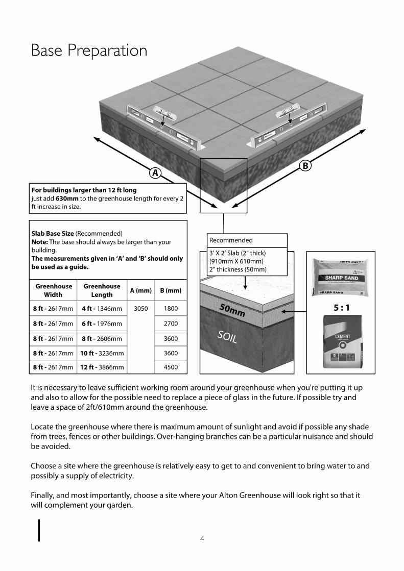
It is necessary to leave sufficient working room around your greenhouse when you're putting it up and also to allow for the possible need to replace a piece of glass in the future. If possible try and leave a space of 2ft/610mm around the greenhouse. Locate the greenhouse where there is maximum amount of sunlight and avoid if possible any shade from trees, fences or other buildings. Over-hanging branches can be a particular nuisance and should be avoided. Choose a site where the greenhouse is relatively easy to get to and convenient to bring water to and possibly a supply of electricity. Finally, and most importantly, choose a site where your Alton Greenhouse will look right so that it will complement your garden.
Base Preparation
1
Greenhouse Width A (mm) B (mm)
8 ft - 2617mm 3050 1800
8 ft - 2617mm 2700
8 ft - 2617mm 3600
8 ft - 2617mm 3600
Slab Base Size (Recommended) Note: The base should always be larger than your building. The measurements given in ‘A’ and ‘B’ should only be used as a guide.
8 ft - 2617mm 4500
Greenhouse Length
4 ft - 1346mm
6 ft - 1976mm
8 ft - 2606mm
10 ft - 3236mm
12 ft - 3866mm
5 : 1
SOIL
50mm
3’ X 2’ Slab (2” thick) (910mm X 610mm) 2” thickness (50mm)
Recommended
For buildings larger than 12 ft long just add 630mm to the greenhouse length for every 2 ft increase in size.

5
Overview
2
25m
m P
an H
ead
(S
tain
less
Ste
el)
40m
m P
an H
ead
(S
tain
less
Ste
el)
50m
m C
ount
ersu
nk (S
tain
less
Ste
el)
80m
m C
ount
ersu
nk (S
tain
less
Ste
el)
Fixes all capping and metalwork
Secures Timber
Cladding
Fixes glazing bars to ridge
and cills
Secures the roof and side
glazing bars to the eaves in
one go!
19m
m P
an H
ead
(S
tain
less
Ste
el)
Fixes the ridge hinge (aluminium
option)
25m
m C
ount
ersu
nk
(Sta
inle
ss S
teel
)
13m
m S
elf T
appi
ng
Used on door metalwork and roof vents
This manual uses a 8 ft x 8 ft greenhouse with 8ft Extension as an example throughout the manual. Look out for tables and extra diagrams showing the varying sizes. You can use the image on the front cover as a reference as to what the greenhouse should look like as you go along. If you are going to treat the greenhouse yourself then it would be best to do it before you begin building the frame. Set out your metal base on your prepared site, but don’t fix this down until the greenhouse is complete. Follow the manual and build the sections as recommended. When screwing through one piece of timber into another it is always recommended to predrill the first piece. This will prevent the timber from splitting which could weaken the structure. You can build the sides of the main building and the extension flat on the ground and then with help or using a prop position the first standard side ready for installation. You then work your way around the greenhouse connecting each section. The front gable is the next section to install, followed by the other standard side and then the extension sides. You then attach the rear gable. Once you have completed the gables and sides you can install the ridge and the roof. If for some reason you want the extension section at the front (maybe the location of a partition would cause this) simply turn the extension 180 degrees and fit the right side on the left and vice versa.
To build you new greenhouse you will need the following tools: Spirit Level Pencil PZ2 Screwdriver Bit Cordless Screwdriver (2 would be ideal, 1 to drill and 1 to screw) 4mm Drill Bit 7mm Masonry Bit Hammer Drill Hammer Step ladders There are 7 different types of screws used in the construction of the greenhouse. These are as follows, with examples of where to look out for them:

6
Overview
2
Glazing the structure is very simple but be very careful of the edges of the glass as the pane will break into tiny peaces if you catch an edge on a hard surface such as concrete. You should also wear suitable gloves when handling the glass (this also helps to keep it clean). It is good practice to pre-load the bar capping with screws and position this around the greenhouse ready for you when you arrive with the glass.
During glazing you will also need to fit the louvre vents so make sure you have these built and ready to slot in. These fit between 2 pieces of glass and are held in place by the capping system. Then fit the roof vent. This is done from the inside, gain access through the opening on a set of steps. All you have left to do now is fit the gutter and downpipes, think about where you might site a waterbutt when doing this. You can always add a Partition or another Extension at a later date so consider this when you are siting your greenhouse. Option of gluing joints. This is not required for strength but you may do it if you wish. However bare in mind if you ever intend to move or adapt the greenhouse in the future this would make it very difficult. The best glue for this would be Poly Urethane Wood Adhesive. Take care when applying this, you only need a very small amount as the glue expands to fill the joint. If you use too much it may seep out of the joint and could be unsightly! Try a test piece before you start. Read through the rest of this manual before starting, you are less likely to miss something doing this and you will have a better understanding of how it all works.

7
Base Assembly
3
Standard Side
EV0294
Lay out your aluminium base sections as the diagram shows. Insert bolts in the bolt channels for attaching the base brackets (D174M), diagram 1. The base brackets should always be positioned either side of the door, in the corners, in the middle of the rear and equally spaced down the sides. Use the joining bracket in each corner to join the sections (diagram 1). The top holes will take a 25mm screw when the side cills are fixed to it. Also fit the front door cill with 2 plates (HE512), diagram 2. Use the larger plates at an extension point (EV0312), diagram 3. Don’t fix any of the base brackets to the ground until the building is complete.
Extension Base Part Name Part
Number Size
(mm) Qty
Extension Side EV0307 2519 2
Joining Bracket EV0312 - 2
Base Bracket D174M - 4
EV0294
EV0288
Dia. 2
Dia. 1
EV0311
D174M
Extension base
EV0299
Internal
Diagram 1
EV0288 HE512
EV0294
Internal
Diagram 2
EV0299 Dia. 3
Standard Side
D174M EV0307
Diagram 3
EV0307M
EV0312M
Standard Side
Internal
8
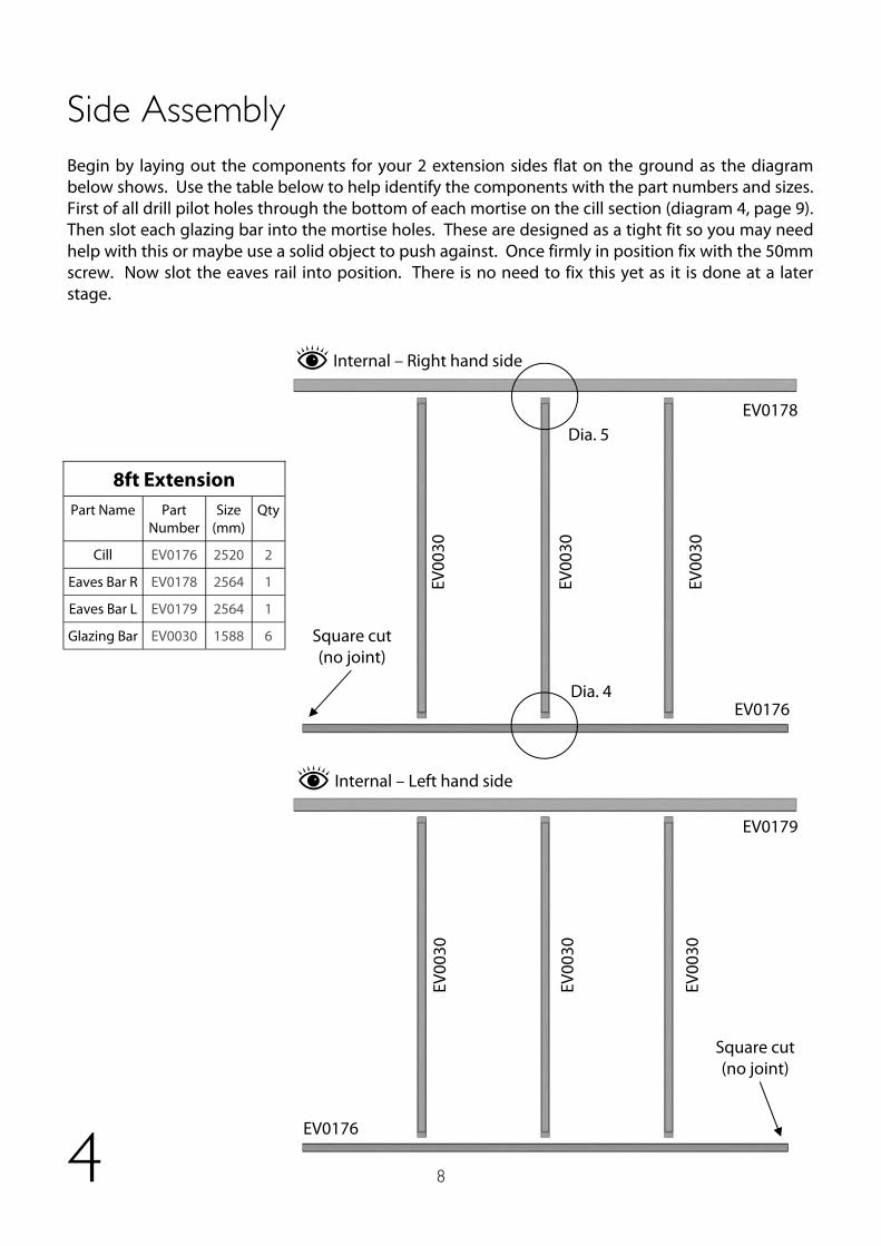
Begin by laying out the components for your 2 extension sides flat on the ground as the diagram below shows. Use the table below to help identify the components with the part numbers and sizes. First of all drill pilot holes through the bottom of each mortise on the cill section (diagram 4, page 9). Then slot each glazing bar into the mortise holes. These are designed as a tight fit so you may need help with this or maybe use a solid object to push against. Once firmly in position fix with the 50mm screw. Now slot the eaves rail into position. There is no need to fix this yet as it is done at a later stage.
Side Assembly
4
EV0176
EV0178
EV00
30
Dia. 4
Dia. 5
EV00
30
Internal – Right hand side
EV0179
EV0176
EV00
30
EV00
30
EV00
30
EV00
30
Internal – Left hand side
Square cut (no joint)
Square cut (no joint)
Part Number
Size (mm)
Qty
EV0176 2520 2
EV0179 2564 1
EV0030 1588 6
8ft Extension Part Name
Cill
Eaves Bar L
Glazing Bar
Eaves Bar R EV0178 2564 1

9
Side Assembly
4
Diagram 4
EV0176
EV00
30
EV0176
EV00
30
EV00
30
EV0021
Diagram 5
Make sure the side bars are pushed all the way in, you may find they need a light tap with a wooden mallet or something similar. (If you are going to glue your joints this is the first point you would do this. ) 50
mm
Scr
ew
Pilot hole, it is easiest to drill
down through the middle of the
mortise to make sure you get the
hole in the correct position
Internal
Internal

10
Front Assembly
Diagram 8
25mm Screw Side Cill
Side Base
EV00
30
Internal
Diagram 6
EV0056
Eaves Bar
External
(Outside Edge)
To install this section you will need a helper to hold the side in position or strap it to a set of steps. Drill two pilot holes in the bottom of the side corner bar as in diagram 6. The height of these holes should be about 15mm on the side face and 25mm on the rear face measured from the end of the bar, try to keep these at different heights to each other so the screws don’t intersect each other. Now offer the side corner to the eaves bar slotting the tennon into the mortise shown in diagram 5, do not fix this joint as it will be done at a later stage. Screw the bottom of the corner glazing bar to the end of the cill (80mm screw) making sure the rebate for the glass lines up with the front face of the side cill (diagram 6).
Once the side corner bar is in place this will give you the correct position on the aluminium base and you can fix the base to the side cill with 25mm screws (diagram 7). 5
Diagram 7
80mm Screw
EV00
56
16mm 16mm
Side
Face Front Face
15m
m
25m
m
Side Cill
External
Keep faces in line
Dia. 7 Dia. 8
Dia. 6
11
Front Assembly
5
Diagram 9
50m
m S
crew
EV
0069
EV0006
External
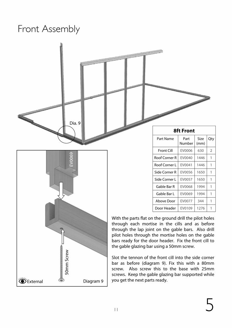
With the parts flat on the ground drill the pilot holes through each mortise in the cills and as before through the lap joint on the gable bars. Also drill pilot holes through the mortise holes on the gable bars ready for the door header. Fix the front cill to the gable glazing bar using a 50mm screw. Slot the tennon of the front cill into the side corner bar as before (diagram 9). Fix this with a 80mm screw. Also screw this to the base with 25mm screws. Keep the gable glazing bar supported while you get the next parts ready.
Part Number
Size (mm)
Qty
EV0006 630 2
EV0040 1446 1
EV0041 1446 1
8ft Front Part Name
Front Cill
Roof Corner R
Roof Corner L
Side Corner R EV0056 1650 1
Side Corner L EV0057 1650 1
Gable Bar R EV0068 1994 1
Gable Bar L EV0069 1994 1
Door Header EV0109 1276 1
Above Door EV0077 344 1
Dia. 9

12
Front Assembly
5
Fix the opposite gable bar and cill in the same way. Before you install the roof corner bars you need to fix the
door header in place.
Slot the door header into the mortise holes and fix with a 50mm screw
through each end (diagram 10).
Make sure the gable bars are well supported while doing this.
Diagram 11 External
Drill through the bottom of the tennon in the door header (EV0109) then fix the glazing bar above the door with a 50mm screw.
50m
m S
crew
EV0109
EV00
77
Diagram 10
EV00
68
EV0109 50mm Screw
External
Dia. 10 Dia. 11

13
Front Assembly
5
40mm Screw
EV00
68
EV0041
Now fit the roof corner bars to the front end. As before, fix the lap joint at the top of the gable bar first with 40mm screws (diagram 17) then secure the bottom end to the eaves bar with a 80mm screws (diagram 18).
Diagram 12
Internal
EV0041
EV00
56
80m
m S
crew
Diagram 13
42mm
External
Dia. 12
Dia. 13

14
Extension Installation
6
Take the first side extension section and slot the small flat piece of timber in the mortise joint. Drill 2 pilot holes and fix this in place with two 40mm screws. Now take this to the aluminium base and slide it up to the other side section. With help or the aid of a prop screw the cill to the base using 25mm screws.
Fix with 25mm screws
Diagram 14
Diagram 15
Dia. 14
Dia. 15
25mm Screw
EV0183 EV0179
Standard Eaves Bar
EV0176
Standard Cill

15
Extension Installation
6
Next fit the side extension bar, first slot the tennon on the end of the bar into the mortise in the cill. Slot the top into position, lining the edge of the bar up with the joint of the two eaves bars. Secure this with a 50mm screw and the secure the bottom with a 40mm screw., remember to drill a pilot hole first.
Diagram 16
Diagram 17
Dia. 16
Dia. 17
40mm Screw
25mm Screw
EV0179
Standard Eaves Bar EV
0184
EV01
84
EV0176
Standard Cill

16
7
Rear Assembly
Take the second side extension section and place it on the base. Fix this as before .
Part Number
Size (mm)
Qty
EV0011 2536 1
EV0040 1446 1
EV0041 1446 1
8ft Rear Part Name
Cill
Roof Corner R
Roof Corner L
Side Corner R EV0056 1650 1
Side Corner L EV0057 1650 1
Gable Bar R EV0060 1994 1
Gable Bar L EV0061 1994 1
Mid Gable Bar EV0074 2214 1
Now fit the final 2 side corner bars as before. See diagram 7 for the position of the holes. Don’t fix the top of the bar until the roof corner bars have been fitted.

17
7
Rear Assembly
EV00
60
EV00
61
EV0011
Dia. 18
Pilot hole here
Locate the rear cill and rear gable glazing bars (these are different to the front gable glazing bars as they do not have the mortise for the door header). Start by drilling pilot holes in the cill section through the mortise holes as before (diagram 8). Also drill 2 holes in the top of the gable glazing bars through the lap joint location. These should be 25-30mm apart and the first hole should be a similar distance from the very top edge (see right) Assemble the gable glazing bars with the rear cill flat on the ground as you did with the side sections. Again with the aid of a helper or using a prop position the rear end onto the aluminium base. Locate the end of the cill into the mortise on the side corner bars.
30m
m
30m
m
EV00
61
EV0011
EV0060
Pilot hole
50m
m
Diagram 18 Internal
Internal
NB there are no mortise holes on these gable bars.
EV00
74

18
Rear Assembly
7
Now fit the roof corner bars to the rear end. Secure these to the gable glazing bars, diagram 19. Now fix the roof corner bar and side corner bar through the eaves bar with an 80mm screw. You can then screw the base to this section with a 25mm screw.
EV00
61
EV0041
40mm Screw
EV0041
EV00
57
80m
m S
crew
Diagram 19
Diagram 20
42mm EV0178
Internal External
Dia. 20
Dia. 19

19
A-frame Assembly
8
Diagram 21
You can start building the A-frame next. Take the eaves extension braces and locate them in the mortise slots in the extension side bars. Pilot hole and fix these with 40mm screws. Make sure the flat face that meets the side bar is seated correctly before fixing.
Dia. 21
40mm Screw
EV01
81
EV01
84
20
A-frame Assembly
8
Diagram 22
Diagram 23
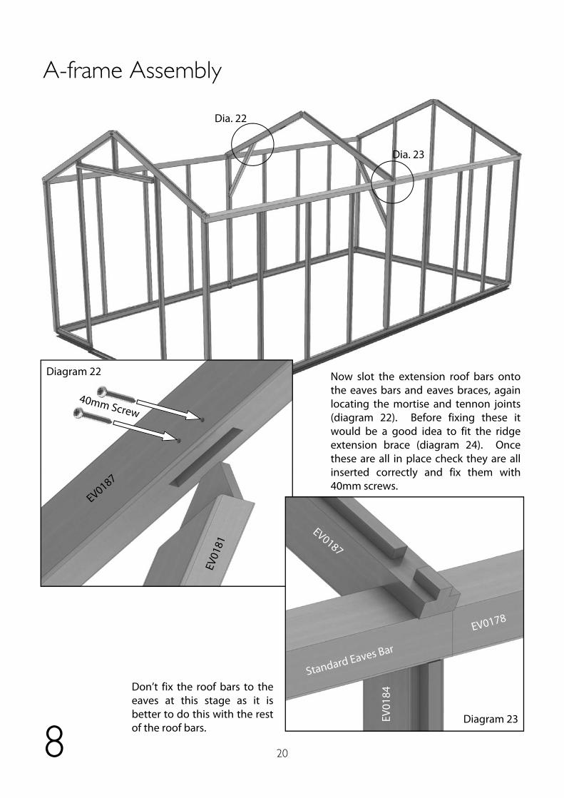
Now slot the extension roof bars onto the eaves bars and eaves braces, again locating the mortise and tennon joints (diagram 22). Before fixing these it would be a good idea to fit the ridge extension brace (diagram 24). Once these are all in place check they are all inserted correctly and fix them with 40mm screws.
Dia. 22
Dia. 23
Don’t fix the roof bars to the eaves at this stage as it is better to do this with the rest of the roof bars.
40mm Screw
EV0187
EV01
81
Standard Eaves Bar
EV0178
EV0187
EV01
84

21
A-frame Assembly
8
Diagram 24
Dia. 24
40mm Screw
EV0187
EV0187

22
Roof Assembly
9
Now install the ridge sections. Firstly fit the ridge extension plate (this is the same part as the eaves braces). Drill 4 pilot holes as in diagram 25. Space these about 50-60mm apart with an 80-90mm gap in the middle so that the fixing screws don’t interfere with the ridge joint. Fix this the extension ridge while on the ground. Lift it into position and slot one end into the rear of the greenhouse and rest the other end on top of the A-frame (diagram 26).
Diagram 25
80m
m S
crew
50mm
50mm 80mm
Dia. 27
Dia. 25+26
EV0180
EV0090

23
Roof Assembly
9
Diagram 26
Now its in position drill 2 pilot holes into the end as in diagram 27. Try to keep the angle something close to diagram 28, through the top face of the roof corner bars. This is to prevent the end or the screw coming through the bottom of the roof glazing bar. This angle will also give a much better and stronger fixing.
Diagram 28
Dia. 28
80mm Screw
50mm
Screw
Optimum screw angle
EV0040 EV0041
Ridge
External
Diagram 27
X-ray
EV0180
EV0090
EV0187
EV0187
EV0041 EV0040

24
Roof Assembly
9
Diagram 29
Next install the main ridge section, locate this with the roof corner bars on the front of the building. Fix this as before and then fix the ridge plate to the main ridge as shown in diagram 25 with 80mm screws. Now the ridge bars are installed you can return to section 7 on page 19 of your main book to complete the assembly of the building.
Dia. 29
EV0180
Standard Ridge Bar
EV0090
EV0187

25
Parts List Part Code Description EVEIGEXT8
EV0024 Eaves Spacer 8
EV0030 Glazing Bar Side 6
EV0033 Glazing Bar Roof 8ft wide 6
EV0090 Eaves Brace 5
EV0091 Ridge Brace 2
EV0176 Cill Side Extension 2
EV0178 Eaves Bar Extension R 1
EV0179 Eaves Bar Extension L 1
EV0180 Ridge Extension 1
EV0181 Eaves Extension Brace 2
EV0183 Eaves Extension Plate 2
EV0184 Glazing Bar Side Extension 2
EV0187 Glazing Bar Roof Extension 8ft wide 2
EV0192 A‐Frame Brace 8ft Wide 1
EV0239M ALU Gutter 8ft Extension 2
EV0299M ALU Rear Base 8ft wide 2
EV0325 Evolution complete louvre kit 2
EVPACVENT Vent pack bundle 2
EVSMA03X Evolutions smalls bag for extension No 3 1
THAUTO CLASSIC AUTO‐VENT 2

Alton Greenhouses, TGP Ltd, Blythe Park, Cresswell, Stoke-on-Trent, ST11 9RD
Telephone: 01782 385 409 www.Altongreenhouses.co.uk [email protected]