evo4 user manual - precisionautoresearch.com product... · powering wiring to the vehicle chassis...
TRANSCRIPT

EVO4
User manual

EVO4User manualRelease 1.01
www.aim-sportline.com 1
Dear customer EVO4 belongs to the last generation of AIM data acquisition systems for car/bike installation: a powerful, compact, reliable and expandable logger with integrated GPS. Thanks to ECT1 it is possible to instantaneously connect it to the vehicle ECU. Supported ECU database is constantly updated. Refer to download area/ documentation section of www.aim-sportline.com for further information. EVO4 allows to monitor RPM, speed, engaged gear, lap (split) times standard and custom sensors. The kit includes, beside EVO4, beacon equipment, GPS antenna and CAN/RS232 cable. EVO4 is a modular datalogger and communicates via CAN bus with:
• Channel expansion: AIM channels expansion; • TC Hub: AIM thermocouples multiplier; • LCU-ONE Lambda controller – the best way to keep under control the engine
Stoichiometric ratio; • MemoryKey – the simple and quick way to save data and transfer to your Pc
Sampled data can also be shown connecting to EVO4 a high tech AIM display like MyChron3 Dash, keeping everything under control in a glance. Thanks to Race Studio 2 it is possible to configure the logger, download and analyze data. Thanks for choosing EVO4!
1 AIM Easy Connection Technology.
EVO4User manualRelease 1.01
www.aim-sportline.com 2
Index Chapter 1 – EVO4 technical features and kit...................................................................3
1.1 – EVO4 kits and spare parts part numbers............................................................................................. 4 1.2 – Optional part numbers.......................................................................................................................... 4
Chapter 2 – EVO4 front view.............................................................................................5 Chapter 3 – Installation and powering .............................................................................6
3.1 – How to power EVO4............................................................................................................................. 6 3.1.1 – GND .............................................................................................................................................. 7
3.2 – The tri-axial accelerometer................................................................................................................... 8 3.3 – How to install the GPS antenna ......................................................................................................... 10 3.4 – How to connect EVO4 to the ECU ..................................................................................................... 11 3.5 – How to sample RPM........................................................................................................................... 12
3.5.1 – Sampling the RPM via CAN bus/RS232..................................................................................... 12 3.5.2 – Sampling RPM from the ECU through a square wave signal..................................................... 12 3.5.3 – Sampling the RPM from the coil: RPM low voltage input ........................................................... 13
3.6 – Installing and powering the IR transmitter and receiver..................................................................... 16 3.6.1 – The infrared (IR) transmitters...................................................................................................... 16 3.6.2 – The infrared (IR) receiver............................................................................................................ 17
3.7 – How to install EVO4 display ............................................................................................................... 18 3.8 – GPS lap timer through the displays.................................................................................................... 18
3.8.1 – GPS lap timer configuration........................................................................................................ 18 3.8.2 – How to configure GPS lap timer on MyChron3 Dash. ................................................................ 18 3.8.3 – Il software GPS Manager............................................................................................................ 20
Chapter 4 – EVO4: software, driver, configuration, transmission, data download, online function .................................................................................................................21 Chapter 5 – EVO4 memory..............................................................................................22 Chapter 6 – EVO4 maintenance......................................................................................23 Appendix – Technical drawings .....................................................................................24

EVO4User manualRelease 1.01
www.aim-sportline.com 3
0Chapter 1 – EVO4 technical features and kit Here below are explained EVO4 technical features, standard kit and optional. Technical features:
• integrated GPS Module; • 5 configurable analog channels; • 2 speed inputs; • 1 RPM channels; • 1 internal tri-axial accelerometer; • Lap time (magnetic/optic/GPS); • ECU Interface; • CAN protocol for external expansion modules; • 8 Mb Memory; • USB port for data download;
• 5 KHz sampling frequency; • 8/18 V external power.
The kit includes: • EVO4; • GPS antenna; • Infrared transmitter with power cable; • Infrared receiver; • RPM cable; • ECU interface cable; • USB data download cable; • CD Race Studio 2.
Optional: • Display Mycron3 Dash; • Expansions; • RPM adapter (only to sample an inductive RPM signal from the spark plug); • External MemoryKey for data backup; • Infrared split transmitter.
EVO4User manualRelease 1.01
www.aim-sportline.com 4
71.1 – EVO4 kits and spare parts part numbers
EVO4 kits are distinguished by the length of the GPS antenna cable and of the receiver power cable.
• Kit EVO4 with 4 m antenna and 90 cm receiver cable X60E44090 • Kit EVO4 with 4 m antenna and and 140 cm receiver cable X60E44140 • Kit EVO4 with 4 m antenna and and 300 cm receiver cable X60E44300 • Kit EVO4 with 1,3 m antenna and 90 cm receiver cable X60E41309 • Kit EVO4 with 1,3 m antenna and 140 cm receiver cable X60E41314 • Kit EVO4 with 1,3 m antenna and 300 cm receiver cable X60E41330
Spare parts part number:
• RPM cable V0256302 • Serial/CAN cable V0256303 • USB cable V0256301
81.2 – Optional part numbers
MyChron3 Dash: X30VDAM01 MemoryKey for data back up: X50MEPC00 Data hub (with 150 cm cable): X08HUB150 Channel expansion: X08CHEXUC TC Hub: X08UTCCTC LCU-ONE CAN Lambda Controller: X08LCU03K0 Infrared split transmitter: X02TXSPLIT0

EVO4User manualRelease 1.01
www.aim-sportline.com
1Chapter 2 – EVO4 front view
EVO4 front view shows 11 connectors and a led placed bottom on the right. Connectors are for:
• Speed: two speed inputs;
• Beacon: optical/magnetic beacon input;
• ECU: ECU CAN/RS232;
• Exp.: AIM expansions connection (Channel Expansion, TC Hub, LCU-ONE, MemoryKey);
• RPM: RPM input and K line connection;
• CH1, CH2, CH3, CH4, CH5: analog channels inputs The led placed bottom on the right has a double function. It switches on when EVO4 is powered and shows logger status according to this scheme.
• Led blinking 1Hz: EVO4 in stand by • Led steady: EVO4 is recording • Led blinking 3 Hz: configuration not OK • Led blinking with alternate colors: logger is updating firmware.
The top lateral cable is GPS antenna cable. The bottom lateral cable is power cable.
5

EVO4User manualRelease 1.01
www.aim-sportline.com 6
2Chapter 3 – Installation and powering Install EVO4, its expansions and display in a place where the devices are not in contact with heat sources or electromagnetic interference sources like spark plugs and coil.
93.1 – How to power EVO4
EVO4 needs a 8-18 VDC non stabilized power source. It is suggested to power EVO4 through the vehicle master switch to save vehicle battery charge.

EVO4User manualRelease 1.01
www.aim-sportline.com
2 53.1.1 – GND For a correct powering and sensors signal stability it is suggested to connect cable labelled GND of EVO4 powering wiring to the vehicle chassis earth as highlighted in the figure below.
7

EVO4User manualRelease 1.01
www.aim-sportline.com
1 13.2 – The tri-axial accelerometer.
EVO4 is equipped with an internal tri-axial accelerometer that is automatically configured by the software according to the way the logger is installed on the vehicle. To set the accelerometer follow this procedure:
• activate channels layer (shown here below);
• click twice on the accelerometer to set; the panel here below appears;
• select the position corresponding to EVO4 installation; the system highlights the selection red circling the selected button;
8

EVO4User manualRelease 1.01
www.aim-sportline.com
• the system automatically sets the three accelerometer axles as shown here below.
Once the channel is set it is possible to verify if it corresponds to the logger position double clicking on the channel. The panel before appears showing the position corresponding to that setting. Refer to Race Studio Configuration user manual, freely downloadable from the website www.aim-sportline.com for further information concerning channels setting.
9

EVO4User manualRelease 1.01
www.aim-sportline.com
1 23.3 – How to install the GPS antenna
In order to get the GPS work properly pay attention when installing the antenna on the vehicle. Install it far from heat sources and let the antenna cable pass as far as possible from electromagnetic sources (i.e. coil or alternator). In case of car installation place the antenna on the vehicle roof so that the antenna can fix steady on the metallic surface. In case the surface where the antenna is to be installed is not ferrous it is suggested to use a piece of 3M Velcro® to correctly fix it to the vehicle chassis.
In case of bike installation place the antenna on the bike tail, where the surface is flat and looking upwards.
10

EVO4User manualRelease 1.01
www.aim-sportline.com
1 33.4 – How to connect EVO4 to the ECU
EVO4 can sample data coming from the vehicle ECU using the proper CAN/RS232 interface cable. To be sure that the vehicle ECU is supported by EVO4 and for further updated information concerning ECU – AIM loggers connection refer to the related documentation freely downloadable from AIM corporate website at the following link: http://www.aim-sportline.com/pages/download/section_documentation_ecu.htm In case non-standard CAN or RS232 lines need to be converted, it is suggested to contact our technical support. Always refer to the ECU user manual for any further information concerning pins and cables connection. To connect EVO4 to the vehicle ECU use the connector labelled ECU placed on the back of the logger. Refer to the appendix technical drawings for further information. Using the CAN line the connection is:
• CAN +: pin 3 white cable labelled CAN + • CAN –: pin 5 blue cable labelled CAN -
Using the RS232 line the connection is: • RS232RX pin 4 white cable labelled RS232RX • RS232TX pin 1 blue cable labelled RS232TX
Using K line the connection is: • K line pin 4 yellow cable labelled K line.
4
5
2
1
3
5 pins Binder 712 male connector pinout – solder termination view.
11
EVO4User manualRelease 1.01
www.aim-sportline.com
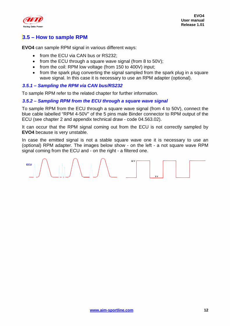
1 43.5 – How to sample RPM
EVO4 can sample RPM signal in various different ways:
• from the ECU via CAN bus or RS232; • from the ECU through a square wave signal (from 8 to 50V); • from the coil: RPM low voltage (from 150 to 400V) input; • from the spark plug converting the signal sampled from the spark plug in a square
wave signal. In this case it is necessary to use an RPM adapter (optional). 1 73.5.1 – Sampling the RPM via CAN bus/RS232 To sample RPM refer to the related chapter for further information. 1 83.5.2 – Sampling RPM from the ECU through a square wave signal To sample RPM from the ECU through a square wave signal (from 4 to 50V), connect the blue cable labelled “RPM 4-50V” of the 5 pins male Binder connector to RPM output of the ECU (see chapter 2 and appendix technical draw - code 04.563.02). It can occur that the RPM signal coming out from the ECU is not correctly sampled by EVO4 because is very unstable. In case the emitted signal is not a stable square wave one it is necessary to use an (optional) RPM adapter. The images below show - on the left - a not square wave RPM signal coming from the ECU and - on the right - a filtered one.
ECU
0 V
12 V
12

EVO4User manualRelease 1.01
www.aim-sportline.com
To connect the RPM adapter follow this procedure.
• Connect cable labelled RPM-ECU 4-50 V to ECU RPM output; • Connect the blue cable of the adapter, “labelled RPM form” to “RPM form 8-50
Volt square wave” input of EVO4. • Connect the red cable of the interface labelled “V battery” to the battery positive
pole. It is suggested to connect the red cable downstream the vehicle master switch.
• Connect the interface black cable, labelled GND to the logger GND pin (refer to the appendix technical draw code 04.563.02 for further information).
1 93.5.3 – Sampling the RPM from the coil: RPM low voltage input To sample RPM signal from the coil on a low voltage RPM input (from 150 to 400V), connect 5 pins Binder 712 male connector pin to ECU RPM output using the white cable labelled RPM 150-450V (see appendix technical draw code 04.563.02).
4
5
2
1
3
It can occur that RPM signal produced by the coil is not correctly sampled by EVO4 because the signal is very unstable.
13
EVO4User manualRelease 1.01
www.aim-sportline.com
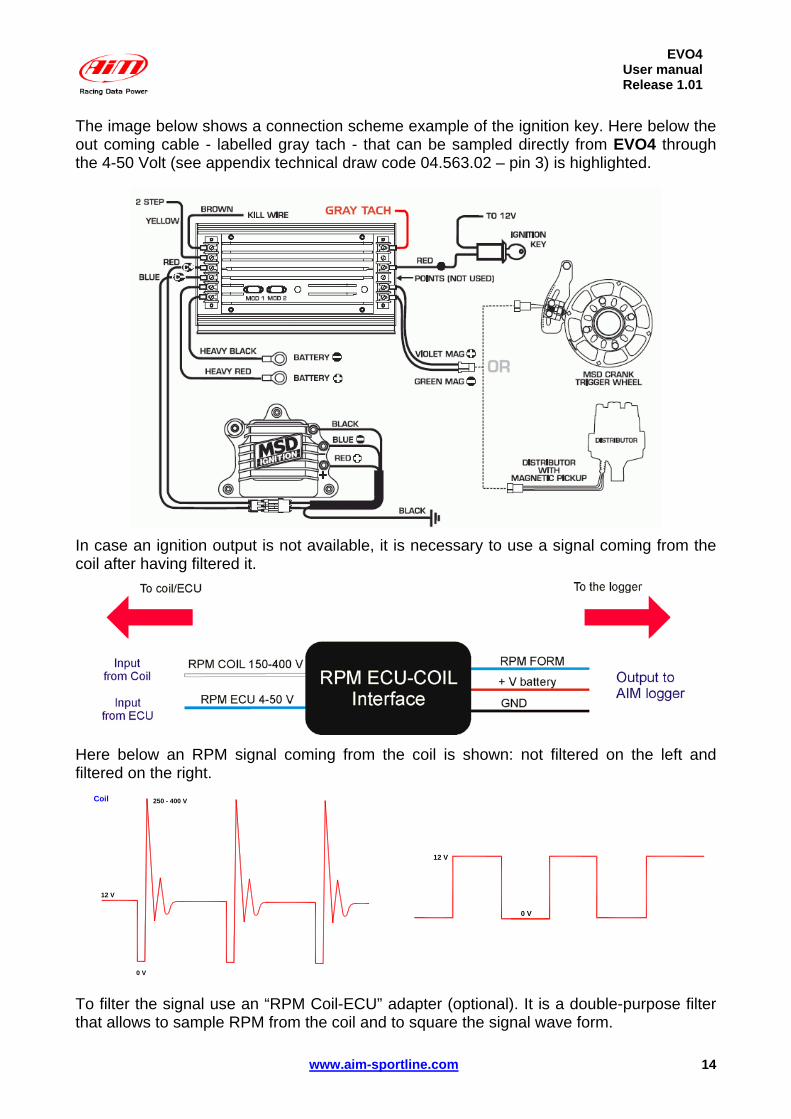
The image below shows a connection scheme example of the ignition key. Here below the out coming cable - labelled gray tach - that can be sampled directly from EVO4 through the 4-50 Volt (see appendix technical draw code 04.563.02 – pin 3) is highlighted.
In case an ignition output is not available, it is necessary to use a signal coming from the coil after having filtered it.
Here below an RPM signal coming from the coil is shown: not filtered on the left and filtered on the right.
Coil
12 V
250 - 400 V
0 V
0 V
12 V
To filter the signal use an “RPM Coil-ECU” adapter (optional). It is a double-purpose filter that allows to sample RPM from the coil and to square the signal wave form.
14

EVO4User manualRelease 1.01
www.aim-sportline.com
The coil to sample the signal from, shown here below, is a black cylinder with three cables (1,2 and 3 labelled). Cable labelled 1 is the coil low tension input. Cable labelled 2 is connected to the coil. Cable labelled 3 is connected to the battery positive pole (+12V). Moreover the coil is generally grounded with the chassis as shown by the scheme below on the right.
+ 12 Volt
TO Sparks
RPM signal "Trigger"
GNDTO Chassis
3
2
1
The scheme below shows the voltage in the points labelled 1,2 and 3 in the images here above.
It is reminded that the adapter white cable, labelled “RPM-Coil 150-400 V” is to be connected to the RPM trigger wiring indicated by digit 1 in the above schemes.
15

EVO4User manualRelease 1.01
www.aim-sportline.com
1 53.6 – Installing and powering the IR transmitter and receiver
AIM provides a range of beacon equipments: 2 03.6.1 – The infrared (IR) transmitters AIM provides two kinds of transmitter:
• the lap transmitter; • the split transmitter; this last one emits a different signal and EVO4 can
distinguish the two signals. The transmitter can be internally or externally powered:
• internally: with 8 AA batteries (placed in the transmitter case); when battery charge status is low power led starts blinking each second (1Hz);
• externally: with an external 12 V power cable; when battery charge status is low the led starts blinking each second.
The transmitter has 2 working modes:
• Low power mode: for tracks whose width is less than 10 m (30 ft); • High power mode: for tracks whose width is more than 10 m (30 ft); in this second
case external 12V power is necessary and both led switch on when the transmitter is switched on.
16
EVO4User manualRelease 1.01
www.aim-sportline.com
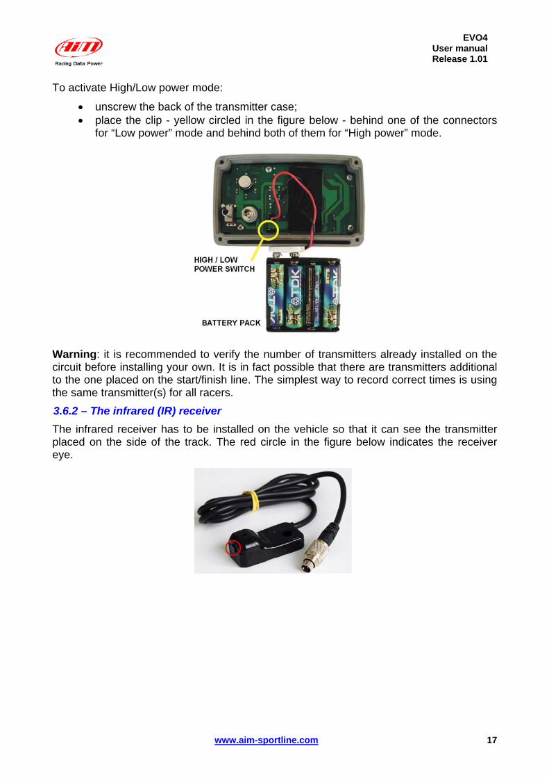
To activate High/Low power mode:
• unscrew the back of the transmitter case; • place the clip - yellow circled in the figure below - behind one of the connectors
for “Low power” mode and behind both of them for “High power” mode.
Warning: it is recommended to verify the number of transmitters already installed on the circuit before installing your own. It is in fact possible that there are transmitters additional to the one placed on the start/finish line. The simplest way to record correct times is using the same transmitter(s) for all racers. 2 13.6.2 – The infrared (IR) receiver The infrared receiver has to be installed on the vehicle so that it can see the transmitter placed on the side of the track. The red circle in the figure below indicates the receiver eye.
17
EVO4User manualRelease 1.01
www.aim-sportline.com
1 63.7 – How to install EVO4 display
EVO4 can be connected to an AIM display to see channels and alarms during the race. At present, available display is MyChron3 Dash. Information shown in the different display pages can be configured by the user through Race Studio 2 software. For further information concerning the display configuration refer to Race Studio Configuration user manual downloadable from www.aim-sportline.com and to the display user manual.
1 03.8 – GPS lap timer through the displays
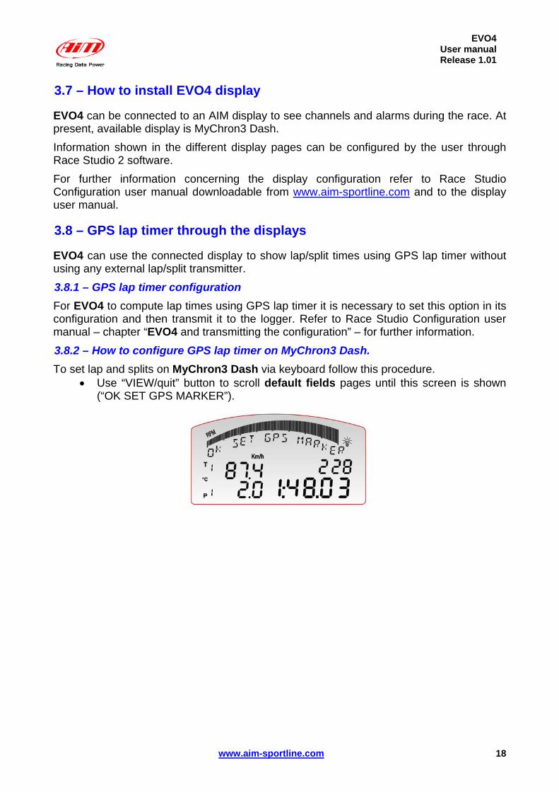
EVO4 can use the connected display to show lap/split times using GPS lap timer without using any external lap/split transmitter. 2 23.8.1 – GPS lap timer configuration For EVO4 to compute lap times using GPS lap timer it is necessary to set this option in its configuration and then transmit it to the logger. Refer to Race Studio Configuration user manual – chapter “EVO4 and transmitting the configuration” – for further information. 2 33.8.2 – How to configure GPS lap timer on MyChron3 Dash. To set lap and splits on MyChron3 Dash via keyboard follow this procedure.
• Use “VIEW/quit” button to scroll default fields pages until this screen is shown (“OK SET GPS MARKER”).
18

EVO4User manualRelease 1.01
www.aim-sportline.com
• Press “MEM/OK” button to start lap/split setting procedure. In case EVO4 configuration has a split setting the screen here below appears (“OK TO SET SPLIT 1”). Split number is set via software.
• Run a track lap to select the physical points where to set lap and split markers. • Press “MEM/OK” button on MyChron3 Dash keyboard in the point where to set
the split. • Repeat this operation as many times as all splits are set. • Once set the splits, the screen asking for lap marker setting - shown here below -
appears (“OK TO SET LAP”). In case no split is set in the logger configuration this screen appears immediately after “lap timer starting setup” one (“OK SET GPS MARKER). Press “MEM/OK” button in the point where lap marker is to be set.
• Once lap marker is set, GPS lap timer setting procedure is over and the display
shows a confirmation screen (“GPS MARKER END”). This screen appears only if the procedure has been successfully completed.
Starting from this moment MyChron3 Dash automatically samples lap/split times using the GPS signal only.
19

EVO4User manualRelease 1.01
www.aim-sportline.com
In case the procedure has not been correctly completed the screen here below appears.
In case GPS memory is full, the screen here below appears.
To empty GPS memory (that stores tracks memorization) it is necessary to use GPS Manager software, freely downloadable form download/software section of AIM website www.aim-sportline.com. Refer to GPS Module user manual for further information concerning the use of GPS Manager and the management of GPS through this software. To disable this function it is necessary to re-configure EVO4 disabling use GPS lap timer option. 2 43.8.3 – Il software GPS Manager. EVO4 integrated GPS can store tracks and the related settings; these information are managed through GPS Manager, the software properly developed by AIM. For further information on the subject refer to GPS Module user manual.
20

EVO4User manualRelease 1.01
www.aim-sportline.com 21
3Chapter 4 – EVO4: software, driver, configuration, transmission, data download, online function
EVO4 connects easily to a PC through the USB cable and can be configured only through Race Studio 2, the powerful software properly developed by AIM to configure its loggers and analyze data. EVO4 standard kit includes the USB cable and Race Studio 2 and USB driver installation CD.
Warning: the logger can be configured only after software and driver installation. Periodically check on www.aim-sportline.com new releases of Race Studio 2
software and/or EVO4 firmware.
Race Studio Configuration user manual, downloadable from download area of AIM corporate website www.aim-sportline.com, includes all information concerning:
• how to install Race Studio 2 under Microsoft Windows XP®, Microsoft Windows Vista® (32 bit only);
• how to configure EVO4 and set its channels; • how to configure EVO4 CAN expansions and set their channels; • how to configure EVO4 display and set its channels; • setting and managing standard and custom sensors; • calibrating and auto-calibrating sensors; • transmitting the configuration to EVO4 once set; • gear calculation; • data download; • online function.

EVO4User manualRelease 1.01
www.aim-sportline.com
4Chapter 5 – EVO4 memory EVO4 is equipped with an internal flash memory whose characteristics are:
• 8 Mb; • non volatile (data are stored also when the logger is off); • round (when it is full, new data automatically overwrite the old ones).
Memory roundness implies an automatic over-writing of old data. To avoid loosing data it is suggested to set each channel sampling frequency on a value that guarantees a sufficient amount of time. Channels sampling frequency is set using Race Studio 2 software. In the image here below - showing channel layer - the case ‘Available time’ is highlighted. It shows the time available with the sampling frequency currently set on each channel.
Modifying each channel sampling frequency available time can increase or decrease. Refer to Race Studio Configuration user manual for further information concerning channels setting and their sampling frequency.
22

EVO4User manualRelease 1.01
www.aim-sportline.com 23
5Chapter 6 – EVO4 maintenance EVO4 needs no special maintenance. Just take care of the logger and its components; the only suggested maintenance is a periodic software/firmware updating: Updates are constantly released by AIM and issued on www.aim-sportline.com download firmware / software area. To update firmware/software it is necessary to:
• Connect to www.aim-sportline.com. • Click on “Download area”. • Click on the corresponding section depending on what is to be updated: software
or firmware. • Select the software/firmware to be updated. • Check if any update has been released. • Download and run them double clicking on them. • Follow the instructions that appear on the PC monitor.
EVO4User manualRelease 1.01
www.aim-sportline.com
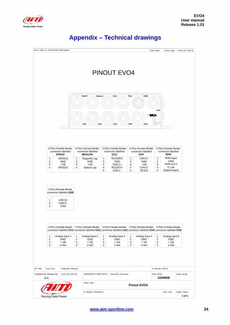
6Appendix – Technical drawings
Speed Beacon ECU Exp. RPM
CH1 CH2 CH3 CH4 CH5
Usb
Materiale / MaterialQ.tà / Q.tyRif. / Ref.
Progettato da / Designed by Contr. da / Ckd. by Approvato da / Approved by Nome file / File name Data / Date
N. articolo / Item N.
Scala / Scale
Foglio / SheetRev. / Rev.
Titolo / Title
N. disegno / Drawing N.
N.rev. / Rev. N. Descrizione / Description Data / date Firma / Sign Contr. da / Ckd. by
Racing Data Power
Pinout EVO4
10/09/08
1 of 1
L.I.
PINOUT EVO4
4 Pins Female Binderconnector labelled
SPEEDSPEED1
GND+VB
SPEED2
4 Pins Female Binderconnector labelled
BEACONMagnetic Lap
GND+VB
Optical Lap
5 Pins Female Binderconnector labelled
ECU12345
1234
1234
5 Pins Female Binderconnector labelled
EXP12345
CAN 0+GND+VB
CAN 0-VB Ext.
5 Pins Female Binderconnector labelled
RPMRS232RX
GNDCAN 1+
RS232TXCAN 1-
12345
RPM InputGND
RPM 4-8 VK Line
Digital Output
3 Pins Female Binderconnector labelled USB
4 Pins Female Binderconnector labelled CH1
4 Pins Female Binderconnector labelled CH2
4 Pins Female Binderconnector labelled CH3
4 Pins Female Binderconnector labelled CH4
4 Pins Female Binderconnector labelled CH5
123
USB D+USB D-
GND
1234
Analog Input 1GND+ VBV Ref
1234
Analog Input 2GND+ VBV Ref
1234
Analog Input 3GND+ VBV Ref
1234
Analog Input 4GND+ VBV Ref
1234
Analog Input 5GND+ VBV Ref
24

EVO4User manualRelease 1.01
www.aim-sportline.com
2
1
4
3GND
14 3 2
213
2
1
3
D+
D-
D+
GND
08-07-08
D-
N.rev. / Rev. N. Descrizione / Description Data / date Firma / Sign
Materiale / MaterialQ.tà / Q.tyRif. / Ref.
Progettato da / Designed by Contr. da / Ckd. by Approvato da / Approved by Nome file / File name Data / Date
N. articolo / Item N.
Scala / Scale
Foglio / SheetRev. / Rev.
Titolo / Title
N. disegno / Drawing N.
Contr. da / Ckd. by
Racing Data Power
USB cable for EVO4
Male USB A typestandard connectorTop view
USB male connector pinoutFrontal view
3 pins Binder 712male connector
3 pins Binder 712male connector pinoutSolder termination view
D.B.
USB cable for EVO4
04.563.03 1 of 1
Male USB A typestandard connectorTop view
25

EVO4User manualRelease 1.01
www.aim-sportline.com
D.B.
04.563.02 1 of 1
1 2 3 4
45
21
3
5
Hea
t Shr
ink
1
Materiale / MaterialQ.tà / Q.tyRif. / Ref.
Progettato da / Designed by Contr. da / Ckd. by Approvato da / Approved by Nome file / File name Data / Date
N. articolo / Item N.
Scala / Scale
Foglio / SheetRev. / Rev.
Titolo / Title
N. disegno / Drawing N.
N.rev. / Rev. N. Descrizione / Description Data / date Firma / Sign Contr. da / Ckd. by
Racing Data Power
RP
M, g
ear f
lash
and
K li
ne c
able
for E
VO
4
5 pi
nsB
inde
r 712
mal
e co
nnec
tor
5 pi
ns -
Bind
er 7
12m
ale
conn
ecto
r pin
out
Sol
der t
erm
inat
ion
view
5x0.
25 m
m² c
able
5x0.
25 m
m² c
able
WH
ITE
BLA
CK
RE
D
BLU
E
OR
AN
GE
WH
ITE
BLA
CK
BLE
U
YE
LLO
W
GR
EY
Cav
o 1x
05 m
m²
Cav
o 1x
05 m
m²
Cav
o 1x
05 m
m²
Cav
o 1x
05 m
m²
Cav
o 1x
05 m
m²
RP
M 1
50-4
50 V
GN
D
RP
M 4
-50
V
LIN
EA K
OU
T D
IGIT
ALC
-01
Boa
rdsi
de 1
ALC
-01
Boa
rdsi
de 2
Cavo RPM, gear flash e linea K per EVO4
26

EVO4User manualRelease 1.01
www.aim-sportline.com
1x0.
5mm
² cab
le
D.B.
1 of 1
CA
N +
1
GN
D2 3 4
CA
N -
RS
232
TX
45
21
3
5
RS
232
RX
1x0.
5mm
² cab
le
1x0.
5mm
² cab
le
1x0.
5mm
² cab
le
1x0.
5mm
² cab
le
1
Term
oret
raib
ile
Materiale / MaterialQ.tà / Q.tyRif. / Ref.
Progettato da / Designed by Contr. da / Ckd. by Approvato da / Approved by Nome file / File name Data / Date
N. articolo / Item N.
Scala / Scale
Foglio / SheetRev. / Rev.
Titolo / Title
N. disegno / Drawing N.
N.rev. / Rev. N. Descrizione / Description Data / date Firma / Sign Contr. da / Ckd. by
Racing Data Power
EV
O4
EC
U C
AN
and
ser
ial c
able
5x0.
25 m
m² c
able
Bin
der 7
125
pins
mal
eco
nnec
tor
Bin
der 7
125
pins
mal
e co
nnec
tor p
inou
tSo
lder
term
inat
ion
view
5x0.
25 m
m² c
able
120
Ohm
SM
Dre
sist
or
ALC
-01
boar
dsi
de 1
ALC
-01
boar
dsi
de 1
Cavo ECU seriale e CAN per EVO4
04.563.01
BLAC
K
WH
ITE
WH
ITE
BLE
U
BLE
UW
HIT
E
BLAC
K
RE
D
BLE
U
OR
AN
GE
27