evolution and trends of vlsi design methodologies and...
TRANSCRIPT
Evolution and Trends of VLSI Design
Methodologies and CAD Tools
Presenter : Raj Singh
IC Design GroupCEERIPilani – 333 031
Tel : 01596-242359
Fax : 01596-242294
Email : [email protected]

Design Methodologies
A View of IC Design
Algorithm
Architecture
Technology
CAD
c©CEERI, Pilani IC Design Group 1
Design Methodologies
Complexity of VLSI Design Task
• Problem Domain Complexity:
– Competing or contradictory requirements (speed, power, area).
– “Impedance mismatch” between users and designers.
– Application area specialization and knowledge.
– Changing/evolving specifications.
– Specification capture issues.
– Cost of design/development.
c©CEERI, Pilani IC Design Group 2
Design Methodologies
�
�
Complexity of VLSI Design Task
• Design/Development Process Complexity:
– Rapidly changing technology.
– Large task requiring multi-disciplinary team.
– Geographically separate design teams.
– Large design space.
– Short design cycle.
c©CEERI, Pilani IC Design Group 3
Design Methodologies
�
�
Complexity of VLSI Design Task
• Design/Development Process Complexity:
– First-time success requirement.
– Assuring unity and integrity of design.
– Multiple views/representations each with different characterization.
– Inadequate documentation.
c©CEERI, Pilani IC Design Group 4
Design Methodologies
�
�
Complexity of VLSI Design Task
• Complexity Because of Choices:
– Many technologies/implementation choices (NMOS, CMOS, . . . )
– Many methodologies (FPGA, Semi-custom, Full custom, ASIC, . . . )
– Many logic forms (Dynamic, 2-phase, 4-phase, Static, . . . )
– Combinatorial explosion as one goes down in abstraction level.
– Many possible partitions at each level.
c©CEERI, Pilani IC Design Group 5
Design Methodologies
�
�
Complexity of VLSI Design Task
• Other Complexities:
– Clocking and Timing issues.
– Testing-related issues.
– Packaging-related issues.
– Concurrency of hardware operations.
c©CEERI, Pilani IC Design Group 6
Design Methodologies
Synthesis and Analysis
VLSI/ASIC/FPGA design activity is
Synthesis and then Analysis
at several successive levels of design abstraction.
Synthesis Phase : Proposing a solution of the design problem at a certainlevel of abstraction.
Analysis Phase : Checking that solution for its validity as well as its con-sistency with some other design representation (usually at a different level ofabstraction) and the characterization/evaluation of the design solution.c©CEERI, Pilani IC Design Group 7
Design Methodologies�
�
Synthesis and Analysis
At each level of design abstraction, synthesis and analysis may be used in aloop (iterative procedure) to arrive at an optimal solution.
Synthesis involves creativity and new concepts.
Analysis (except when developing new methods of analysis) involves applyingknown methods for checking the design and processing of large data usingknown/standard methods.
Thus, synthesis has traditionally been the prerogative of humans, while anal-ysis has traditionally been the first task to have been handed over to the com-puters via creation of CAD tools.
When synthesis can be expressed as a method, it can also be carried out bycomputers via CAD tools created for that purpose.c©CEERI, Pilani IC Design Group 8
Design Methodologies
�
�
Synthesis and Analysis
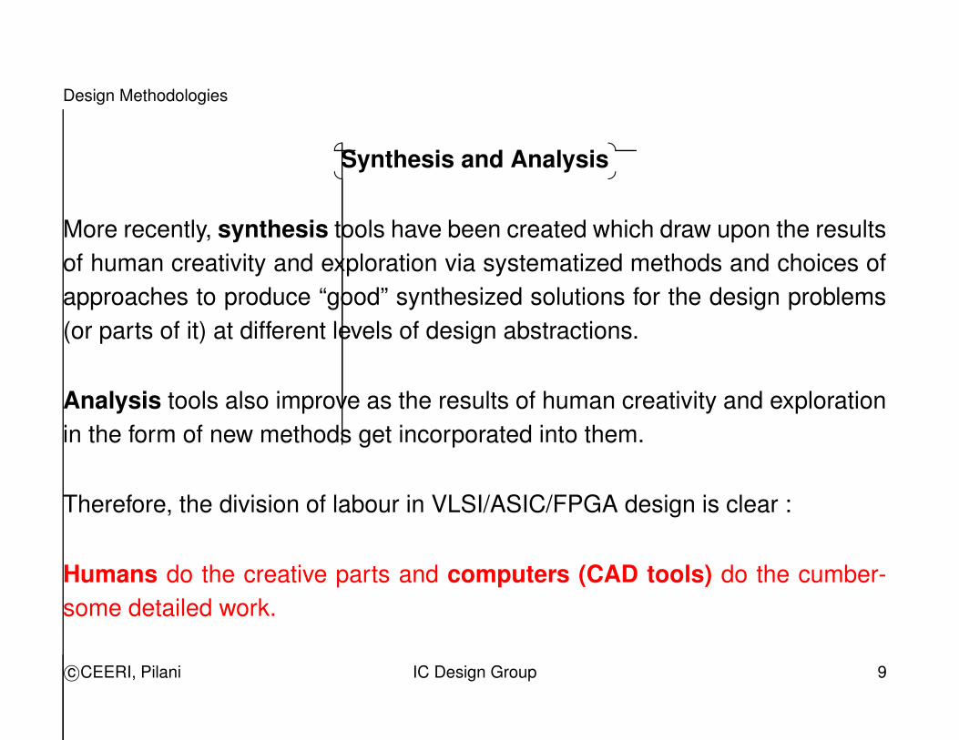
More recently, synthesis tools have been created which draw upon the resultsof human creativity and exploration via systematized methods and choices ofapproaches to produce “good” synthesized solutions for the design problems(or parts of it) at different levels of design abstractions.
Analysis tools also improve as the results of human creativity and explorationin the form of new methods get incorporated into them.
Therefore, the division of labour in VLSI/ASIC/FPGA design is clear :
Humans do the creative parts and computers (CAD tools) do the cumber-some detailed work.
c©CEERI, Pilani IC Design Group 9
Design Methodologies
..
.
. . .
. . .
. . .
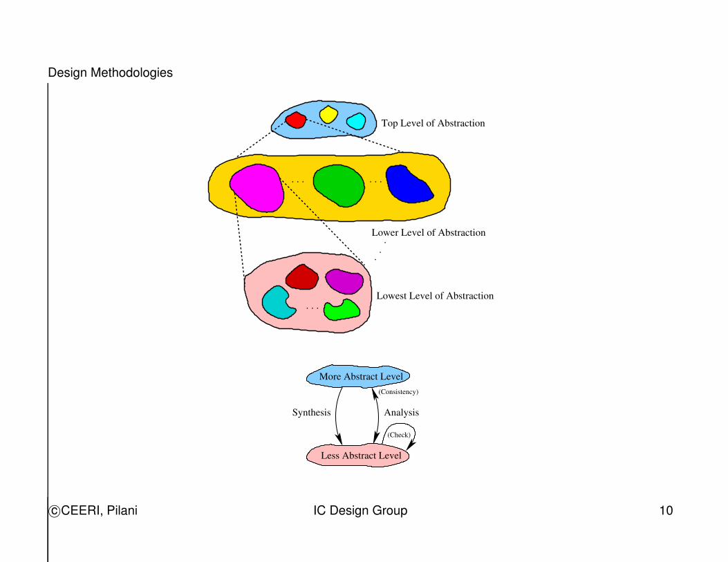
Top Level of Abstraction
Lower Level of Abstraction
Lowest Level of Abstraction
More Abstract Level
Synthesis
(Check)
Analysis
(Consistency)
Less Abstract Level
c©CEERI, Pilani IC Design Group 10
Design Methodologies
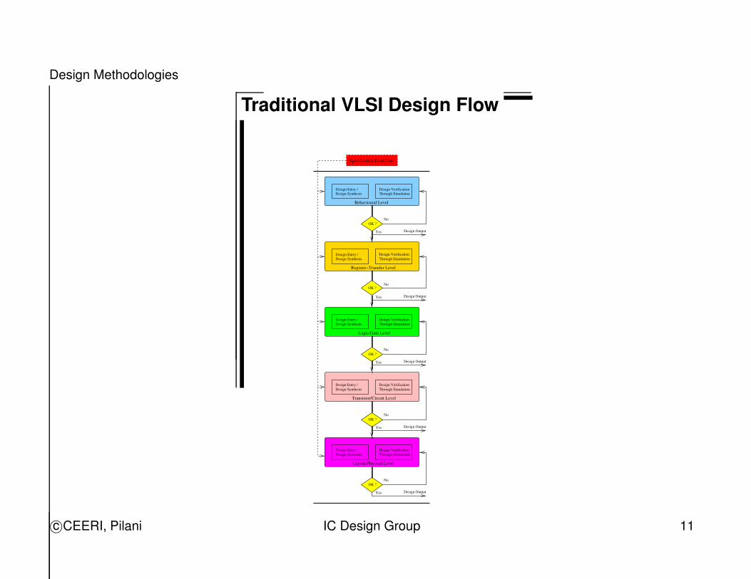
Traditional VLSI Design Flow
Design VerificationDesign Entry /
OK ?
Design Output
Design Entry /
Design Output
Yes
No
No
Yes
OK ?No
Yes Design Output
OK ?No
Yes Design Output
OK ?No
Yes Design Output
Specification From User
OK ?
Design VerificationThrough Simulation
Design Synthesis
Design Synthesis
Design SynthesisDesign Entry /
Transistor/Circuit Level
Layout/Physical Level
Design Entry /Design Synthesis
Design VerificationThrough Simulation
Logic/Gate Level
Design VerificationThrough Simulation
Design VerificationThrough Simulation
Design Entry /Design Synthesis
Register−Transfer Level
Through Simulation
Behavioural Level
c©CEERI, Pilani IC Design Group 11
Design Methodologies
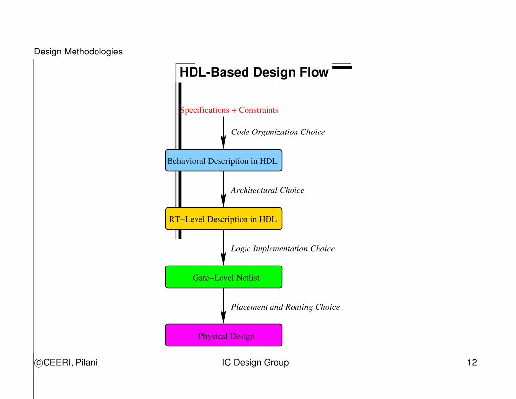
HDL-Based Design Flow
Code Organization Choice
Architectural Choice
Logic Implementation Choice
Placement and Routing Choice
Behavioral Description in HDL
RT−Level Description in HDL
Physical Design
Specifications + Constraints
Gate−Level Netlist
c©CEERI, Pilani IC Design Group 12
Design Methodologies
VLSI Design Methodologies
Systematic design methods (called design methodologies) are necessary forsuccessfully designing complex digital hardware.
Different design methodologies differ in their choice of number and levels ofdesign abstractions used during the design process and the manner of con-straints on the translations between the abstraction levels.
These constraints are usually in the form of use of a particular structure typeat the lower level of design abstraction while translating the design descriptionthat exists at a higher level of abstraction.
c©CEERI, Pilani IC Design Group 13
Design Methodologies
�
�
VLSI Design Methodologies
For example, while translating from the logic level abstraction to physical level,popular design methodologies are :
1. FPGA/CPLD.
2. Gate-Array.
3. Standard-Cell.
4. Full-Custom.
c©CEERI, Pilani IC Design Group 14
Design Methodologies
�
�
VLSI Design Methodologies
The popular methodologies for implementing the control part are :
1. Hardwired Control.
2. Microcoded ROM-based Control.
3. PLA-based Control.
c©CEERI, Pilani IC Design Group 15
Design Methodologies
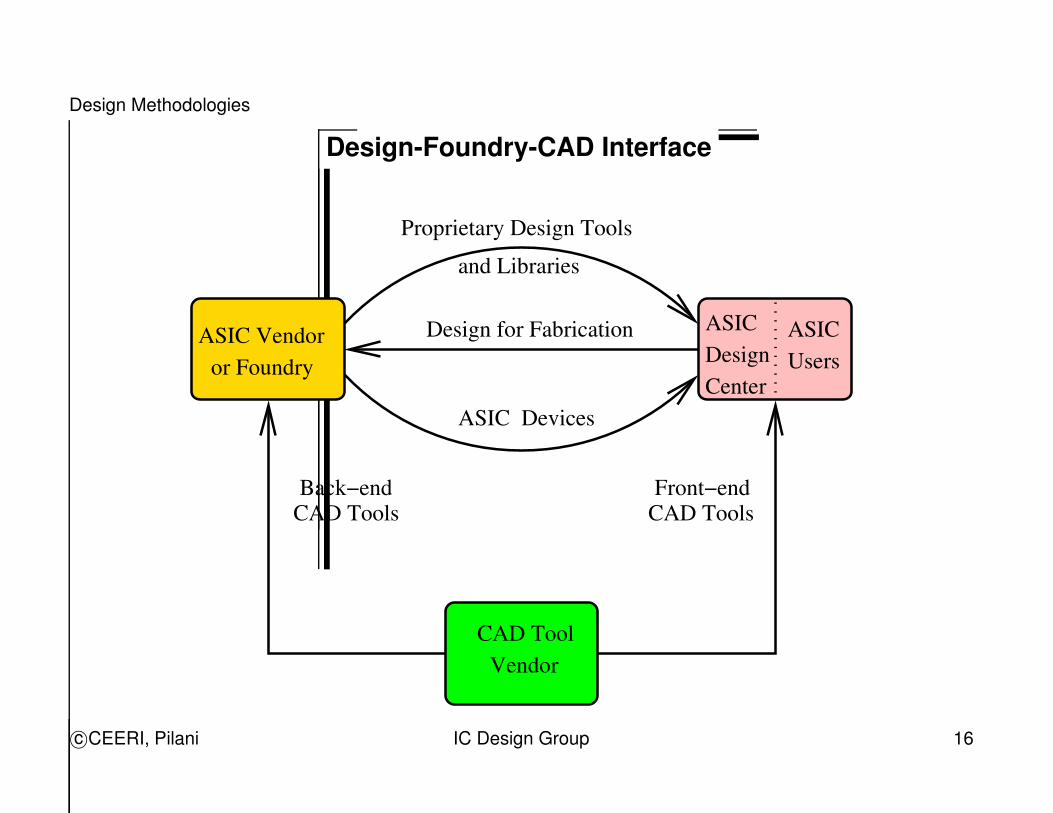
Design-Foundry-CAD Interface
Back−endCAD Tools
Proprietary Design Toolsand Libraries
DesignCenter
ASICUsers
Front−endCAD Tools
ASIC Vendoror Foundry
Design for Fabrication
ASIC Devices
Vendor
ASIC
CAD Tool
c©CEERI, Pilani IC Design Group 16
CAD : An Introduction
Typical Phases of a Product
• Awareness of need and its Identification.
• Design and Development.
• Implementation/Manufacture.
• Testing/Verification/Validation.
• Feed-back and Correction.
• Release/Maintenance.
c©CEERI, Pilani IC Design Group 17
CAD : An Introduction
CAD : Computer Aided Design
What is CAD ?
Any kind of activity which uses a computer to assist in the creation, modifica-tion and analysis of a design.
ECAD : Electronic CAD.
EDA : Electronic Design Automation.
c©CEERI, Pilani IC Design Group 18
CAD : An Introduction
Major Benefits of CAD
• Improved performance and quality of product.
(better engineered products).
• Higher productivity of designers.
• More flexibility to react to market changes and product modifications.
• Provide time to experiment and explore alternatives.
(design space exploration).
c©CEERI, Pilani IC Design Group 19
CAD : An Introduction
CAD Environment : Factors Affecting Design
• Market requirements.
• Manufacturing technology status.
• CAD tool(s) status.
• Human talent available.
c©CEERI, Pilani IC Design Group 20
CAD : An Introduction
CAD Environment : Reducing Risk of Failure
• Simulate performance before fabrication. (simulation)
• Explore various alternatives and characterize them in terms of cost, per-formance, ... (design space exploration)
• Check against all possible known fabrication process violations beforedata is given to manufacturing. (design sign-off)
CAD tools help discover problems so that they can be corrected at minimalcost, both in terms time and resources (catch errors as early as possible).
c©CEERI, Pilani IC Design Group 21
CAD : An Introduction
CAD Tool Components
• Input Handler (input from keyboard/mouse).
• Data Structure + Algorithm (in-memory).
• Output Handler (output to display).
• File Input/Output Handler (to/from disk).
c©CEERI, Pilani IC Design Group 22
Design Methodologies and CAD Tools
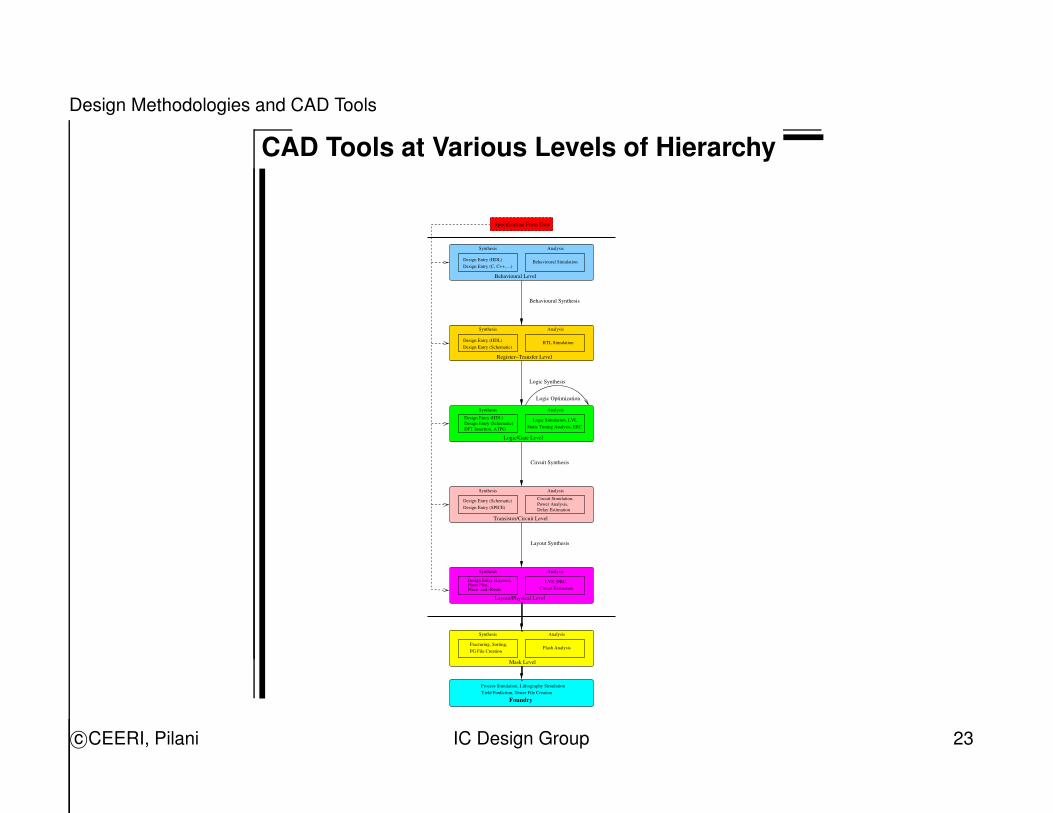
CAD Tools at Various Levels of Hierarchy
Design Entry (HDL)Design Entry (C, C++, ...)
Design Entry (HDL)Design Entry (Schematic)
Specification From User
Behavioural Simulation
Behavioural Level
Behavioural Synthesis
RTL Simulation
Analysis
Synthesis
Synthesis
Logic Simulation, LVL,Static Timing Analysis, ERC
AnalysisSynthesisDesign Entry (HDL)Design Entry (Schematic)DFT Insertion, ATPG
Logic Synthesis
Register−Transfer Level
Logic/Gate Level
Circuit Synthesis
Design Entry (Schematic)Design Entry (SPICE)
Circuit Simulation,Power Analysis,Delay Estimation
Transistor/Circuit Level
AnalysisSynthesis
Layout/Physical Level
LVS, DRC,Circuit Extraction
AnalysisSynthesis
Design Entry (Layout),Floor Plan,Place−and−Route
Flash Analysis
AnalysisSynthesis
PG File CreationFracturing, Sorting,
Process Simulation, Lithography Simulation
Analysis
Logic Optimization
Layout Synthesis
Mask Level
FoundryYield Prediction, Tester File Creation
c©CEERI, Pilani IC Design Group 23
Design Methodologies and CAD Tools
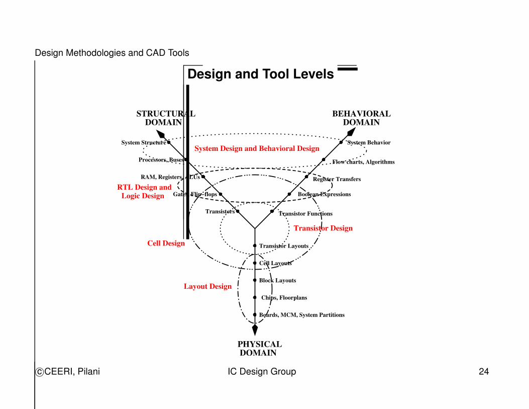
Design and Tool Levels
System Design and Behavioral Design
Layout Design
STRUCTURALDOMAIN
BEHAVIORALDOMAIN
DOMAINPHYSICAL
System Structure
Processors, Buses
RAM, Registers, ALUs
Gates, Flip−flops
Transistors
Transistor Layouts
Cell Layouts
Block Layouts
Chips, Floorplans
Boards, MCM, System Partitions
Transistor Functions
Boolean Expressions
Register Transfers
Flow charts, Algorithms
System Behavior
RTL Design andLogic Design
Transistor Design
Cell Design
c©CEERI, Pilani IC Design Group 24
Design Methodologies and CAD Tools
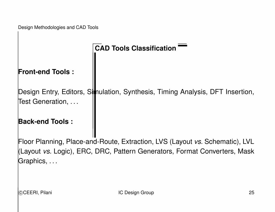
CAD Tools Classification
Front-end Tools :
Design Entry, Editors, Simulation, Synthesis, Timing Analysis, DFT Insertion,Test Generation, . . .
Back-end Tools :
Floor Planning, Place-and-Route, Extraction, LVS (Layout vs. Schematic), LVL(Layout vs. Logic), ERC, DRC, Pattern Generators, Format Converters, MaskGraphics, . . .
c©CEERI, Pilani IC Design Group 25
Design Methodologies and CAD Tools
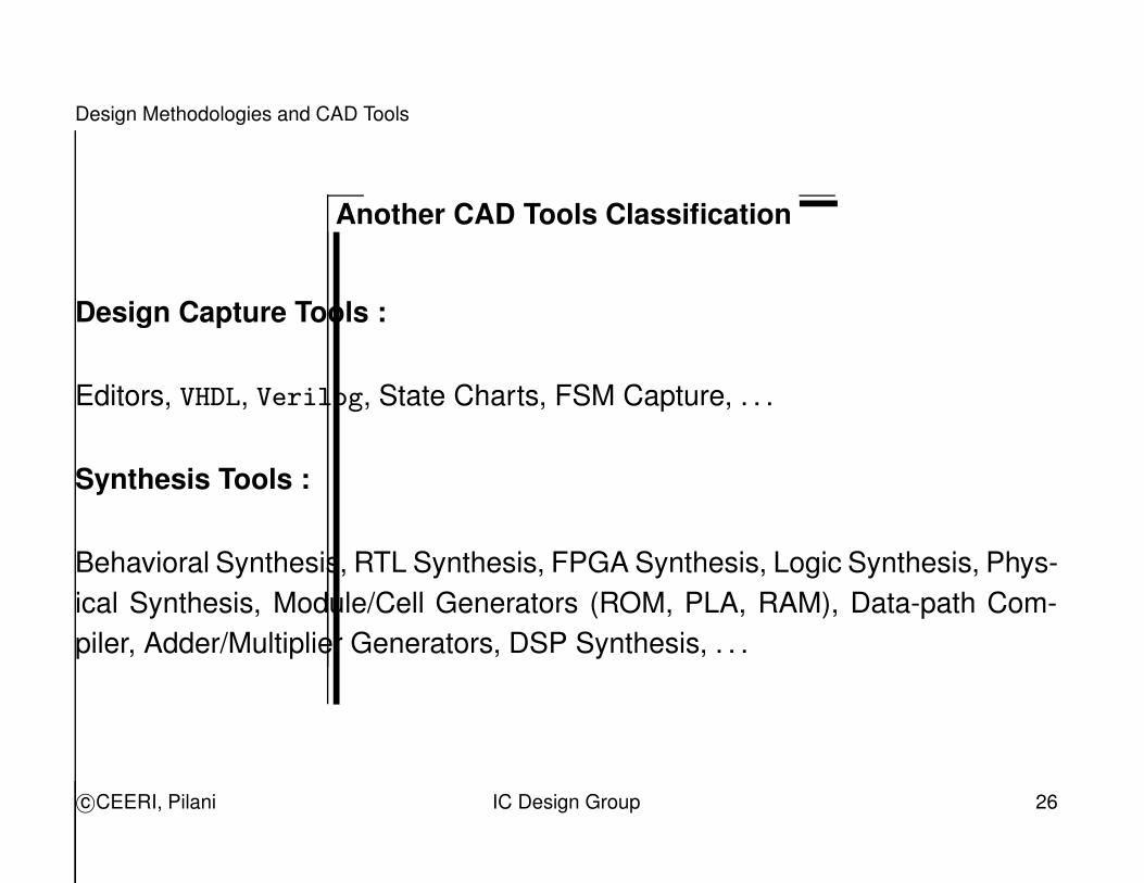
Another CAD Tools Classification
Design Capture Tools :
Editors, VHDL, Verilog, State Charts, FSM Capture, . . .
Synthesis Tools :
Behavioral Synthesis, RTL Synthesis, FPGA Synthesis, Logic Synthesis, Phys-ical Synthesis, Module/Cell Generators (ROM, PLA, RAM), Data-path Com-piler, Adder/Multiplier Generators, DSP Synthesis, . . .
c©CEERI, Pilani IC Design Group 26
Design Methodologies and CAD Tools
�
�
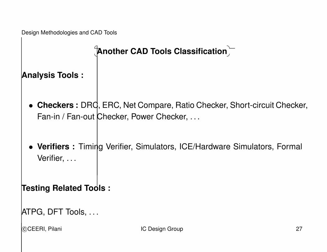
Another CAD Tools Classification
Analysis Tools :
• Checkers : DRC, ERC, Net Compare, Ratio Checker, Short-circuit Checker,Fan-in / Fan-out Checker, Power Checker, . . .
• Verifiers : Timing Verifier, Simulators, ICE/Hardware Simulators, FormalVerifier, . . .
Testing Related Tools :
ATPG, DFT Tools, . . .
c©CEERI, Pilani IC Design Group 27
Design Methodologies and CAD Tools
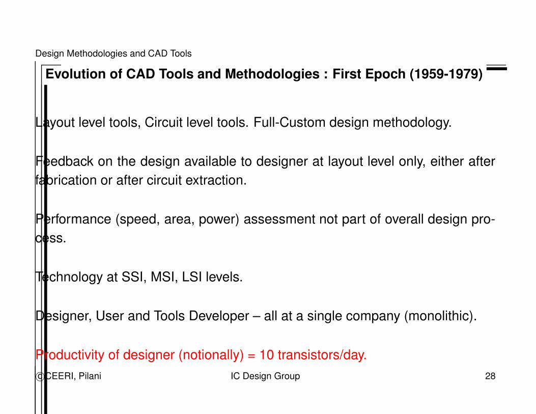
Evolution of CAD Tools and Methodologies : First Epoch (1959-1979)
Layout level tools, Circuit level tools. Full-Custom design methodology.
Feedback on the design available to designer at layout level only, either afterfabrication or after circuit extraction.
Performance (speed, area, power) assessment not part of overall design pro-cess.
Technology at SSI, MSI, LSI levels.
Designer, User and Tools Developer – all at a single company (monolithic).
Productivity of designer (notionally) = 10 transistors/day.c©CEERI, Pilani IC Design Group 28
Design Methodologies and CAD Tools
Evolution of CAD Tools and Methodologies : Second Epoch (1980-1989)
Logic level tools, Macro generators, Module compilers, ASICs, FPGAs.
Shorter synthesis/analysis loop. Standard-Cell / Gate-Array / ASIC designmethodology.
Basic capability of performance feedback and design exploration becomesavailable. However, it is not fully incorporated in the design flow.
Technology at LSI, VLSI levels.
User/Designer separated from Tools Developer i.e. separate companies sellingtools come into being.
Productivity of designer (notionally) = 10 gates/day.c©CEERI, Pilani IC Design Group 29
Design Methodologies and CAD Tools
Evolution of CAD Tools and Methodologies : Third Epoch (1990-1999)
RT-level synthesis, Preliminary Behavioural synthesis tools. HDL-based de-sign entry, HDL Code analyzers/advisers.
Design exploration easier, Estimators for performance become available. HDL-based design methodology.
Technology at VLSI levels. Deep-submicron (DSM) issues.
User, Designer and Tools Developer become separate groups/companies. Fa-bless companies.
CAD tools move towards PC platforms.
Productivity of designer (notionally) = 10 lines of VHDL code/day.c©CEERI, Pilani IC Design Group 30
Design Methodologies and CAD Tools
�
�
Evolution of CAD Tools and Methodologies : Third Epoch (1990-1999)
Low-power gains importance. Mixed-signal design issues.
Tools for designing MEMS and Embedded systems appear.
Intellectual Property, Design Re-use, Reconfigurable Computing, Cores, ASIP,ASSP, DSP, . . .
c©CEERI, Pilani IC Design Group 31
Design Methodologies and CAD Tools
Evolution of CAD Tools and Methodologies : Fourth Epoch (2000 . . . )
System-level synthesis tools, Systems-on-a-Chip (SoC), MEMS/MEOS.
Block-level chip design (using cores, IP blocks). SoC design methodology.
Consolidation among EDA companies.
Technology at VLSI, ULSI levels. Deep-submicron (DSM) issues.
Productivity of designer (notionally) = 10 lines of specification code/day.
RF IC Design, Hardware-Software Codesign, Web-based CAD tools and de-sign environment.
Methodology and Tools for Non-Silicon based Designs ? Nano-technology ?c©CEERI, Pilani IC Design Group 32
Trends : Codesign and Embedded Systems
What is Hardware-Software Codesign ?
Integrated design of electronic systems implemented using hardware and soft-ware components developed concurrently and cooperatively.
It is a part of the system-level design which may consist of mechanical, elec-trical or chemical parts in addition to electronics.
c©CEERI, Pilani IC Design Group 33
Trends : Codesign and Embedded Systems
Advantages of Hardware-Software Systems
• Family of products on a common hardware platform.
• Upgradation and efficient evolution path of product through updating soft-ware.
• Chip/circuit’s high cost reduced by providing functionality in software.
• Range of system costs and performances – from (high cost + high perfor-mance) to (low cost + low performance).
Embedded core, ASIC/FPGA, Microprocessor + Software, . . .
c©CEERI, Pilani IC Design Group 34
Trends : Codesign and Embedded Systems
Application Areas
• Large systems e.g. Aircraft, Telecommunication.
• Computing systems e.g. Supercomputer, Workstation, PC.
• Strategic/Defence systems e.g. Radar, Missile.
• Embedded systems.
– Control e.g. automobile, medical, industrial.
– Hand-held e.g. cellular phone, PDA.
c©CEERI, Pilani IC Design Group 35
Trends : Codesign and Embedded Systems
�
�
Application Areas
– Consumer e.g. microwave oven, washing machine.
– Music systems e.g. MP3 players, Ogg players.
– Sound recording e.g. phone-answering machine.
– Speech processing e.g. voice synthesis.
– Graphics processing e.g. laser printer, X-terminal.
– Video processing e.g. VCR, VCD, DVD, Digital TV, HDTV.
– Robotics and Mechatronics.
c©CEERI, Pilani IC Design Group 36
Trends : Codesign and Embedded Systems
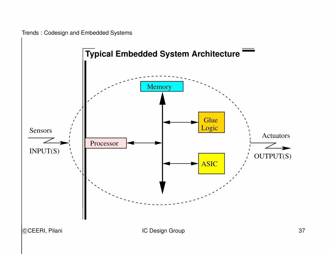
Typical Embedded System Architecture
INPUT(S)OUTPUT(S)
SensorsActuators
Processor
Memory
ASIC
GlueLogic
c©CEERI, Pilani IC Design Group 37
Trends : Codesign and Embedded Systems
�
�
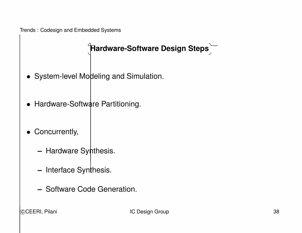
Hardware-Software Design Steps
• System-level Modeling and Simulation.
• Hardware-Software Partitioning.
• Concurrently,
– Hardware Synthesis.
– Interface Synthesis.
– Software Code Generation.
c©CEERI, Pilani IC Design Group 38
Trends : Codesign and Embedded Systems
�
�
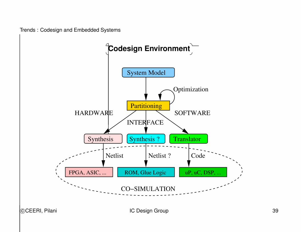
Codesign Environment
System Model
Partitioning
INTERFACE
Netlist Netlist ? Code
CO−SIMULATION
Optimization
TranslatorSynthesis ?Synthesis
SOFTWAREHARDWARE
uP, uC, DSP, ...ROM, Glue LogicFPGA, ASIC, ...
c©CEERI, Pilani IC Design Group 39
Trends : Reconfigurable Computing
What is Reconfigurable Computing ?
Reconfigurable Computing is an approach that allows reconfigurable aspectsof hardware (e.g. FPGAs) to be as flexible as software.
It can be implemented either statically (configure and then repeatedly execute)or dynamically (repeatedly configure-and-execute).
It requires extensive kowledge base and quantitative approach for evaluat-ing different system architectural options vis-a-vis the system requirements(in terms of speed, power, cost, user-interface, configurability, . . . ).
c©CEERI, Pilani IC Design Group 40
Trends : Reconfigurable Computing
Why Reconfigurable Computing ?
• “Virtual” hardware.
• Reduced time-to-market.
• Cheaper than ASICs or processors.
• Better re-use of Silicon than ASICs.
• More application specific adaptation than processors.
• Lower system life-time cost. Also, upgradeable in the field.
c©CEERI, Pilani IC Design Group 41
Trends : Reconfigurable Computing
Types of Reconfigurable Computing
• Rapid Prototyping.
• Hardware Accelerator; Hardware Emulator.
• Processor + FPGA (Embedded Systems).
• Reconfigurable Compiler.
c©CEERI, Pilani IC Design Group 42
Trends : Reconfigurable Computing
�
�
Types of Reconfigurable Computing
• Part-reconfiguration and on-the-fly Reconfiguration.
• Multi-context Architectures.
• Structured ASIC.
c©CEERI, Pilani IC Design Group 43
Conclusion
Conclusion
VLSI Design is a complex task.
CAD tools and design methodologies are important partners of the designer inovercoming this complexity.
CAD tools free the designer from easy-to-do tasks and allow the designer toconcentrate on creative tasks.
Design methodologies and CAD tools evolve based on designer’s needs.
c©CEERI, Pilani IC Design Group 44