evolution e5 dual efi pilot guide · horizontal situation indicator and option to display wind...
TRANSCRIPT

Evolution E5 Dual EFIPilot Guide

Evolution E5 Dual EFI Pilot Guide Page iii091-00086-001 REV A
Evolution E5 Dual EFIPilot Guide
Evolution E5 Dual EFI Pilot GuidePage iv 091-00086-001 REV A
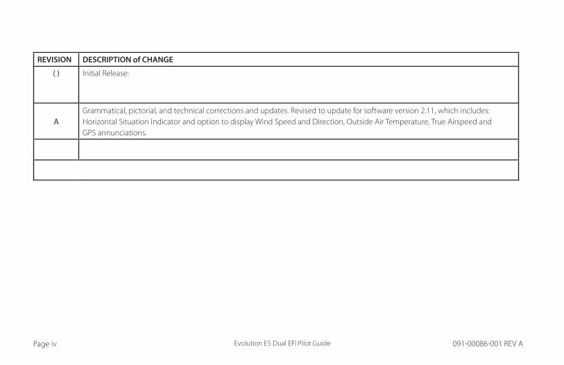
REVISION DESCRIPTION of CHANGE
( ) Initial Release:
AGrammatical, pictorial, and technical corrections and updates. Revised to update for software version 2.11, which includes: Horizontal Situation Indicator and option to display Wind Speed and Direction, Outside Air Temperature, True Airspeed and GPS annunciations.
Evolution E5 Dual EFI Pilot Guide Page v091-00086-001 REV A Page v
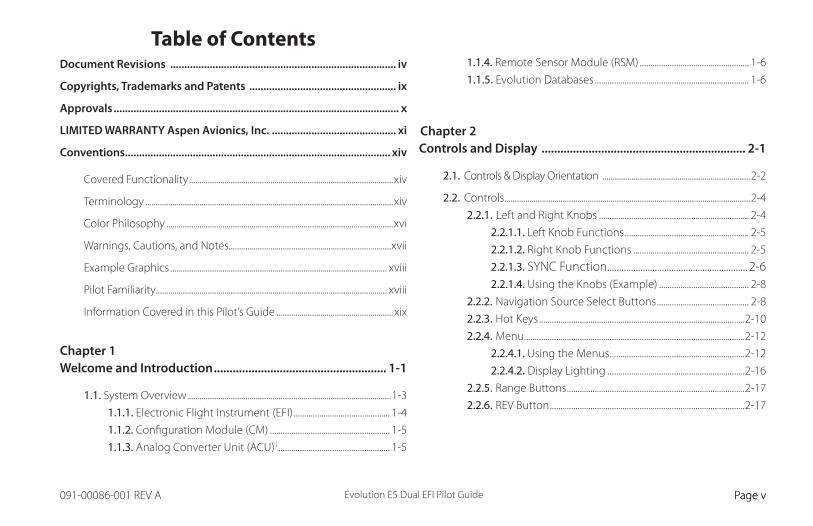
Table of ContentsDocument Revisions ................................................................................ iv
Copyrights, Trademarks and Patents .................................................... ix
Approvals ..................................................................................................... x
LIMITED WARRANTY Aspen Avionics, Inc. ............................................ xi
Conventions.............................................................................................. xiv
Covered Functionality ..................................................................................................xiv
Terminology .......................................................................................................................xiv
Color Philosophy .............................................................................................................xvi
Warnings, Cautions, and Notes..............................................................................xvii
Example Graphics ........................................................................................................ xviii
Pilot Familiarity ............................................................................................................... xviii
Information Covered in this Pilot’s Guide ........................................................ xix
Chapter 1Welcome and Introduction ....................................................... 1-1
1.1. System Overview ..................................................................................................1-3
1.1.1. Electronic Flight Instrument (EFI) ............................................. 1-4
1.1.2. Configuration Module (CM) ........................................................ 1-5
1.1.3. Analog Converter Unit (ACU)1 .................................................... 1-5
1.1.4. Remote Sensor Module (RSM) ................................................... 1-6
1.1.5. Evolution Databases ........................................................................ 1-6
Chapter 2Controls and Display ................................................................. 2-1
2.1. Controls & Display Orientation .......................................................................2-2
2.2. Controls ......................................................................................................................2-4
2.2.1. Left and Right Knobs ...................................................................... 2-4
2.2.1.1. Left Knob Functions .......................................................... 2-5
2.2.1.2. Right Knob Functions ...................................................... 2-5
2.2.1.3. SYNC Function........................................................... 2-62.2.1.4. Using the Knobs (Example) .......................................... 2-8
2.2.2. Navigation Source Select Buttons ........................................... 2-8
2.2.3. Hot Keys ................................................................................................2-10
2.2.4. Menu .......................................................................................................2-12
2.2.4.1. Using the Menus ...............................................................2-12
2.2.4.2. Display Lighting ................................................................2-16
2.2.5. Range Buttons ...................................................................................2-17
2.2.6. REV Button ...........................................................................................2-17
Evolution E5 Dual EFI Pilot GuidePage vi 091-00086-001 REV A
2.3. Display .....................................................................................................................2-18
2.3.1. Cleaning the Display Screen .....................................................2-19
2.3.2. Attitude Display ................................................................................2-20
2.3.2.1. Attitude Indicator (AI) ....................................................2-22
2.3.2.2. Airspeed Tape and Bug .................................................2-23
2.3.2.3. Altitude Tape .......................................................................2-24
2.3.3. Data Bar ......................................................................................2-25
2.3.4. Navigation Display ..........................................................................2-26
2.3.4.1. Numerical Direction Indicator
(Magnetic Compass) .......................................................2-28
2.3.4.2. Horizontal Situation Indicator (HSI) ......................2-30
2.3.4.3. Deviation Off-Scale Indication ............................................2-30
2.3.4.4. Auto Course Select ..........................................................2-30
2.3.4.5. Rate of Turn Indicator ....................................................2-31
2.3.4.6. Vertical Speed Indicator (VSI) ...................................2-32
Chapter 3Flying the Evolution E5 Dual EFI ............................................. 3-1
3.1. Quick Controls Overview .................................................................................3-3
3.2. Example Flight Scenario ...................................................................................3-5
3.2.1. Pre-Departure (Startup) ................................................................. 3-6
3.2.2. Departure .............................................................................................3-13
3.2.3. Enroute ..................................................................................................3-15
3.3. Conclusion ...............................................................................................3-17
Chapter 4Reference Guide ......................................................................... 4-1
4.1. Air Data, Attitude and Heading Reference System (ADAHRS) ..4-2
4.1.1. Attitude.................................................................................................... 4-3
4.1.2. Pitot Obstruction Monitor ............................................................ 4-4
4.1.3. Heading ................................................................................................... 4-5
4.1.4. Free Gyro Mode .................................................................................. 4-6
4.1.5. Degraded Mode ................................................................................. 4-7
4.2. Attitude Display .....................................................................................................4-8
4.2.1. Attitude Indicator .............................................................................. 4-8
4.2.1.1. Roll Scale .................................................................................. 4-9
4.2.1.2. Pitch Scale ............................................................................... 4-9
4.2.1.3. Slip/Skid Indicator .............................................................. 4-9
4.2.2. Lateral and Vertical Deviation Indicator .............................4-10
4.2.2.1. Lateral Deviation Indicator ........................................4-10
4.2.2.2. Vertical Deviation Indicator .......................................4-11
4.2.3. Airspeed Indicator ...........................................................................4-12
4.2.3.1. Selected Airspeed ............................................................4-14
4.2.3.2. Airspeed Display ...............................................................4-15
4.2.4. Altimeter ...............................................................................................4-16
4.2.4.1. Barometric Units of Measure .....................................4-17
4.2.4.2. Selected Altitude Field ..................................................4-19
4.2.4.3. Altitude Display .................................................................4-20

Evolution E5 Dual EFI Pilot Guide Page vii091-00086-001 REV A
4.3. Data Bar ...................................................................................................................4-21
4.3.1. True Airspeed .....................................................................................4-21
4.3.2. Ground Speed ...................................................................................4-22
4.3.3. Outside Air Temperature .............................................................4-22
4.3.4. Wind Speed, Direction, and Arrow ........................................4-23
4.3.5. Barometric Pressure Setting Display .....................................4-23
4.4. Navigation Display ............................................................................................4-24
4.4.1. Compass ..............................................................................................4-25
4.4.1.1. 360° Compass Mode .......................................................4-25
4.4.1.2. ARC Compass Mode .......................................................4-25
4.4.2. Course Pointer ..................................................................................4-27
4.4.3. TO/FROM Indicator .........................................................................4-28
4.4.4. Course Deviation Indicator and Scale .................................4-29
4.4.5. CDI Navigation Source ..................................................................4-30
4.4.6. Auto Course ........................................................................................4-32
4.4.7. CDI Selected Course ......................................................................4-33
4.4.8. Heading Bug .......................................................................................4-34
4.4.9. Aircraft Heading Display ..............................................................4-35
4.4.10. Rate of Turn Indicator .................................................................4-35
4.4.11. Ground Track Marker ...................................................................4-36
4.4.12. GPS OBS Operation with a EFI and a Mechanical
Standby Nav Indicator ...................................................................4-36
4.4.13. Course Pointer Operation with Integrated VOR/GPS
Navigation Systems .........................................................................4-36
4.5. Vertical Speed Indicator ................................................................................4-37
4.6. Autopilot Integration1 .....................................................................................4-38
4.6.1. GPS Steering (GPSS)1 ......................................................................4-39
4.6.2. Typical Autopilot Operations1 ..................................................4-43
Chapter 5Customizing the Evolution E5 Dual EFI .................................. 5-1
5.1. Menu Overview .....................................................................................................5-1
5.2. Configuring Vspeeds ..........................................................................................5-5
5.3. LCD Brightness Control ..................................................................................5-10
Chapter 6Expanded Emergency and Abnormal Procedures ............... 6-1
6.1. Pitot/Static System Blockage ........................................................................6-2
6.1.1. Identifying and Handling Suspected Pitot
and/or Static System Failures ...................................................... 6-3
6.2. Frequent or Persistent CROSS CHECK ATTITUDE
Annunciation .......................................................................................................6-6
6.3. Difference Detected Between the Evolution E5 Dual EFI
and Mechanical Attitude Indicators ..........................................................6-6
6.4. Abnormal Shutdown Procedure .................................................................6-7

Evolution E5 Dual EFI Pilot GuidePage viii 091-00086-001 REV A
6.5. Loss of Aircraft Electrical Power ..................................................................6-8
6.5.1. Overvoltage Protection .......................................................................6-9
6.6. Power Override ...................................................................................................6-11
6.7. In-Flight AHRS Reset ........................................................................................6-12
6.8. GPSS Operation, Annunciations, and Autopilot Modes ............6-14
6.9. Warning, Caution, and Advisory Summary .......................................6-16
Chapter 7Appendices .................................................................................. 7-1
7.1. Operating Limitations ........................................................................................7-1
7.2. Software Versions and Serial Number .....................................................7-1
7.3. Specifications ..........................................................................................................7-3
7.3.1. Electronic Flight Instrument (EFI) ............................................. 7-3
7.3.2. Remote Sensor Module (RSM) .................................................. 7-5
7.3.3. Analog Converter Unit (ACU) ..................................................... 7-5
7.3.4. Operational Specifications ........................................................... 7-6
7.4. Glossary ......................................................................................................................7-7
7.5. Index ..........................................................................................................................7-10

Evolution E5 Dual EFI Pilot GuidePage PB 091-00086-001 REV A Evolution E5 Dual EFI Pilot Guide Page ix091-00086-001 REV A
Copyrights, Trademarks and Patents Copyright 2007-2019.
Aspen Avionics® is a registered trademark of Aspen Avionics, Inc. Evolution™, EFD1000 Pro MAX PFD™, EFD1000 MAX MFD™, EFD500 MAX MFD™, EFD1000™, EFD500™, EFD1000 VFR, Evolution E5 Dual EFI and the Aspen Avionics logo are trademarks of Aspen Avionics, Inc. These trademarks may not be used without the express permission of Aspen Avionics, Inc. All rights reserved.
All other trademarks are the property of their respective companies. No part of the Pilot’s Guide may be reproduced, copied, stored, transmitted, or disseminated, for any reason, without the express written permission of Aspen Avionics, Inc. Aspen Avionics hereby grants permission to download a single copy, and any revision, of the Pilot’s Guide onto a hard drive or other electronic storage medium for personal use, provided that such electronic or printed copy of the Pilot’s Guide or revision must contain the complete text of this copyright notice and provided further that any unauthorized commercial distribution of the Pilot’s Guide or revision hereto is strictly prohibited.
Avidyne® is a registered trademark of Avidyne Corporation; Bendix/King® is a registered trademark of Honeywell; Garmin GTX™is a trademark of Garmin International, Inc.; NavData® is a registered trademark of Jeppesen, Inc.; SkyWatch® is a registered trademark of L-3 Communications; Stormscope® WX-500 is a registered trademark of BFGoodrich Avionics Systems, Inc.; and XM is a registered trademark of XM Satellite Radio, Inc.

Evolution E5 Dual EFI Pilot GuidePage x 091-00086-001 REV A Evolution E5 Dual EFI Pilot Guide Page xi091-00086-001 REV A
ApprovalsThe FAA has approved the Aspen E5 under STC SA10822SC. Installation of the Evolution E5 Dual EFI in a type-certificated airplane must be accomplished by a qualified person in accordance with this STC.
Aspen Avionics, Inc. 5001 Indian School Road NE Suite 100 Albuquerque, NM 87110
Phone: (505) 856-5034 Fax: (505) 314-5440
www.aspenavionics.com

Evolution E5 Dual EFI Pilot GuidePage x 091-00086-001 REV A Evolution E5 Dual EFI Pilot Guide Page xi091-00086-001 REV A
LIMITED WARRANTY Aspen Avionics, Inc.
1. YOUR WARRANTY. Aspen Avionics, Inc. (“Aspen”) warrants to you, the original purchaser, that its Products (if purchased from an authorized dealer) will comply with applicable specifications (as set forth in the owner’s manual) in all material respects and will be free from material defects in workmanship or materials for a period of twenty-four (24) months beginning with the date that the aircraft in which the Product has been installed has been returned to service following installation by an Aspen authorized dealer (“Return to Service Date”). “Product” means new end equipment or hardware items, replaceable units and components of those units.
2. YOUR REMEDY. During the term of this warranty, Aspen will repair or replace, at its discretion, without charge (see Section 13 below for information on covered transportation costs), any Product that does not comply with the warranty of Section 1 above (a “Nonconforming Product”), so long as the warranty claim is timely submitted and the procedures in Section 14 (below) are followed. Aspen warrants repaired and/or replacement items only for the unexpired portion of the original warranty period, or, if the warranty has expired, for six months from Aspen’s shipment of the repaired or replacement Product.
3. CONDITIONS TO COVERAGE. Aspen’s obligation under this warranty is conditioned on your fulfillment of the obligation to:
A. Maintain records accurately reflecting operating time of and maintenance performed on the Product,
B. Furnish proof sufficient to establish that the item is a Nonconforming Product, and
C. Allow Aspen access to all relevant records in order to substantiate your warranty claim.
4. EXCLUSIONS. The following are not covered by (and are expressly excluded from) this warranty:
A. Normal wear and tear and the need for regular overhaul and maintenance,
B. Exposure of the Product to temperature, environmental, operating, or other conditions other than those prescribed in the owner’s manual,
C. Failure to install or operate the Product as prescribed in the owner’s manual or as Aspen otherwise directs,
D. Alterations or repairs made by anyone other than Aspen or its authorized service center,
E. Maintenance, repair, installation, handling, transportation, storage, operation (including, without limitation, operation of the product’s software or host medium), or use which is improper or otherwise does not comply with Aspen’s instructions as set forth in the owner’s manual,

Evolution E5 Dual EFI Pilot GuidePage xii 091-00086-001 REV A Evolution E5 Dual EFI Pilot Guide Page xiii091-00086-001 REV A
F. Accident, contamination, damage from a foreign object or weather conditions, abuse, misuse, neglect, or negligence,
G. Exposure of the product or the product’s host medium to any computer virus or other intentionally disruptive, destructive, or disabling computer code, and
H. Any damage precipitated by failure of a product Aspen has supplied that is not under warranty or by any product supplied by someone else.
5. INVALIDATION OF WARRANTY. This warranty is void if the product is altered or repair is attempted or made by anyone other than Aspen or its authorized service center.
6. WARRANTY CARD. The Return to Service Date must be included in an accurately completed Aspen warranty application form submitted by the installing authorized dealer within 30 days of the Return to Service Date. The warranty application must be signed by the authorized repairman who certifies that the equipment has been safely and properly installed in accordance with all Aspen supplied technical information and in accordance with all applicable FAA procedures and requirements. The warranty application form must note the repairman’s FAA certificate number to be valid. FAILURE TO COMPLETE AND RETURN THE WARRANTY CARD MAY RESULT IN DENIAL OF WARRANTY CLAIMS. MAKING CERTAIN THAT THE WARRANTY CARD IS COMPLETED, SIGNED, AND RETURNED IS YOUR RESPONSIBILITY.
7. SOLE REMEDY. Aspen’s sole obligation, and your exclusive remedy under this warranty, is limited to either the repair or replacement, at Aspen’s option, of any Nonconforming Product as provided herein.
8. EXCLUSIVE WARRANTY. THIS WARRANTY IS EXCLUSIVE AND IN LIEU OF ALL OTHER WARRANTIES. THE IMPLIED WARRANTY OF MERCHANTABILITY AND IMPLIED WARRANTY OF FITNESS FOR A PARTICULAR PURPOSE, AS WELL AS ALL OTHER IMPLIED WARRANTIES (STATUTORY OR OTHERWISE) EXPIRE AT THE END OF THE WARRANTY PERIOD PRESCRIBED IN SECTION 1.
Some States do not allow limitations on how long an implied warranty lasts, so the above limitation may not apply to you.
9. INCIDENTAL DAMAGES. ASPEN SHALL NOT UNDER ANY CIRCUMSTANCES BE LIABLE FOR ANY SPECIAL, DIRECT, INDIRECT, INCIDENTAL OR CONSEQUENTIAL LOSS OR DAMAGES OF ANY KIND (INCLUDING WITHOUT LIMITATION: DAMAGES FOR LOSS OF PROFITS, LOSS OF REVENUES, OR LOSS OF USE OR BUSINESS INTERRUPTION), EVEN IF ASPEN HAS BEEN ADVISED OF THE POSSIBILITY OR CERTAINTY OF THOSE DAMAGES OR IF ASPEN COULD HAVE REASONABLY FORESEEN THOSE DAMAGES.
Some states do not allow the exclusion of incidental or consequential damages, so the preceding limitations may not apply to you.
10. LIMITATION OF LIABILITY. ASPEN’S AGGREGATE LIABILITY HEREUNDER, WHETHER BASED UPON CONTRACT, TORT (INCLUDING NEGLIGENCE AND STRICT LIABILITY), INDEMNITY, OR OTHERWISE, WILL NOT EXCEED THE PRICE PAID BY YOU FOR THE WARRANTED PRODUCT. THE EXCLUSIONS OF TYPES OF DAMAGES CONTAINED HEREIN WILL BE DEEMED INDEPENDENT OF, AND WILL SURVIVE, ANY FAILURE OF THE ESSENTIAL PURPOSE OF ANY LIMITED REMEDY UNDER THE TERMS OF ANY AGREEMENT.

Evolution E5 Dual EFI Pilot GuidePage xii 091-00086-001 REV A Evolution E5 Dual EFI Pilot Guide Page xiii091-00086-001 REV A
11. EXTENSION OF WARRANTY. No extension of this warranty will be binding upon Aspen unless set forth in writing and signed by Aspen’s authorized representative.
12. DEALER WARRANTIES. Any express or implied warranty or remedy in addition to or different from those stated herein that is offered by a dealer (“Dealer Warranty”) will be the sole responsibility of the dealer, who will be solely responsible for all liability, loss, cost, damage, or expense arising out of or in connection with any such Dealer Warranty. Although Aspen provides training and assistance to dealers, it cannot control the installation of its Products by its dealers, which are independent businesses not owned or controlled by Aspen.
13. TRANSPORTATION COSTS. Aspen will assume round trip transportation costs for a Product determined by Aspen to be a Nonconforming Product in an amount not to exceed normal (non express) shipping charges within the continental United States. You are responsible for all import/export fees, taxes, duties, customs, documentation fees, clearance fees, and similar fees and charges. You may contact Aspen to obtain a freight courier account number for prepaid shipping of the return. If Aspen subsequently determines that the Product is not a Nonconforming Product, that this warranty is inapplicable, that the Product is out of warranty, that the defect or malfunction is excluded from coverage, or that the warranty is invalid, Aspen will invoice you for repair or replacement costs and the shipping costs. Risk of loss or damage for any Product in transit will be borne by the party initiating the transportation.
14. WARRANTY PROCEDURE. If you require warranty service, you may contact your local Aspen Authorized Dealer or you may contact Aspen directly as described below. An original or copy of the sales receipt from the original Aspen Authorized dealer will be required to obtain any warranty service. You may contact Aspen for warranty service directly by calling Aspen Customer Service at (505) 856-5034; by writing to Aspen Customer Service Department, Aspen Avionics, Inc., 5001 Indian School Road NE, Albuquerque, New Mexico, 87110; or by visiting the Aspen Website at http://www.aspenavionics.com.
This warranty gives you specific legal rights, and you may also have other rights, which vary from State to State.

Evolution E5 Dual EFI Pilot GuidePage xiv 091-00086-001 REV A Evolution E5 Dual EFI Pilot Guide Page xv091-00086-001 REV A
ConventionsThe following conventions, functionality, terminology, color philosophy, and definitions are used in this manual and on the Evolution E5 Dual EFI.
Covered FunctionalityThis guide covers all the functions available in the Evolution E5 Dual EFI.
TerminologyThe term “Evolution E5 Dual EFI”, is used throughout this Pilot’s Guide and refers to the Evolution E5 Dual Electronic Flight Instrument (EFI).
Figure 1 shows a typical Evolution E5 Dual EFI. This guide uses the terminology list in Table 1 when referring to specific parts of the Evolution E5 Dual EFI and Chapter 4 provides an in-depth discussion and step-by-step instructions for all the available functionality.

Evolution E5 Dual EFI Pilot GuidePage xiv 091-00086-001 REV A Evolution E5 Dual EFI Pilot Guide Page xv091-00086-001 REV A
Term Example
Buttons REV Button, Range Buttons, MENU Button
Hot Keys / Menu Keys Five keys on the lower right of the display
Buttons CDI Navigation Source Select Button (Center Button)
Knobs Left (CRS) Knob, Right (HDG) Knob
Navigation Display
Data Bar
Airspeed, attitude, altitude display
Table 1 Evolution E5 Dual EFI, Knobs, Buttons, and Keys
Figure 1 Evolution E5 Dual EFI, Knobs, Buttons, and Keys

Evolution E5 Dual EFI Pilot GuidePage xvi 091-00086-001 REV A Evolution E5 Dual EFI Pilot Guide Page xvii091-00086-001 REV A
Color PhilosophyTable 2 provides the general operational philosophy of color usage on the Evolution E5 Dual EFI display.
COLOR PURPOSE COLOR PURPOSE
RED
Used to indicate flight envelope and system limits, and for warning annunciations that require immediate pilot recognition and which may require immediate pilot correction or compensatory action. Red is used to indicate Data Link Weather precipitation areas.
GREEN
Used for navigation information or mode data related to or provided by the navigation source currently selected for display on the Course Deviation Indicator (CDI) (i.e., navigation deviations, equipment operating state, waypoint information). Green is also used to indicate Data Link Weather precipitation areas and the status of user controls (i.e., ON, enabled, or active).
AMBER
Used to indicate abnormal information sources, and for caution information that requires immediate pilot awareness and for which subsequent pilot action may be required. Amber is used to indicate Data Link Weather precipitation areas.
WHITE Used to show primary flight data (e.g., IAS, ALT, HDG), scales, and Menu items that are selectable for editing.
MAGENTAUsed for pilot-selectable references (bugs) enabled for editing, for depicting the active GPS navigation leg on a moving map display, and for depicting the flight director bar.
GRAY Used to show supplemental flight data, and for Hot Key and Menu legends that are OFF, disabled, or inactive.
CYANUsed to indicate editable values that are not currently selected for editing. CYAN is also used to display bearing pointers, proximity and other traffic icons, and GPS track marker.
BLUE Used to indicate the sky and Data Link Weather precipitation areas.
BROWN Used to indicate the ground.
Table 2
Evolution E5 Dual EFI Pilot GuidePage xvi 091-00086-001 REV A Evolution E5 Dual EFI Pilot Guide Page xvii091-00086-001 REV A
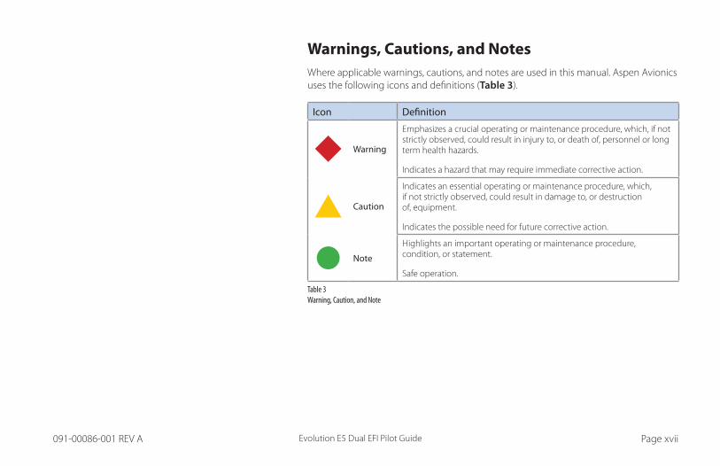
Warnings, Cautions, and NotesWhere applicable warnings, cautions, and notes are used in this manual. Aspen Avionics uses the following icons and definitions (Table 3).
Icon Definition
Warning
Emphasizes a crucial operating or maintenance procedure, which, if not strictly observed, could result in injury to, or death of, personnel or long term health hazards.
Indicates a hazard that may require immediate corrective action.
Caution
Indicates an essential operating or maintenance procedure, which, if not strictly observed, could result in damage to, or destruction of, equipment.
Indicates the possible need for future corrective action.
Note
Highlights an important operating or maintenance procedure, condition, or statement.
Safe operation.
Table 3 Warning, Caution, and Note
Evolution E5 Dual EFI Pilot GuidePage xviii 091-00086-001 REV A Evolution E5 Dual EFI Pilot Guide Page xix091-00086-001 REV A
Example GraphicsThe example graphics and screen shots used throughout this Pilot’s Guide are provided for reference only and are taken from a simulated flight. They should not be used for actual flights.
Pilot FamiliarityWhile the Evolution E5 Dual EFI is reasonably intuitive and easy to use, some familiarity with Evolution E5 Dual EFI required. Aspen Avionics strongly recommends that new users get some dual instruction from an experienced instrument CFI, and spend some time becoming familiar with the Evolution E5 Dual EFI.
E5 OverviewThe Evolution E5 Dual EFI system is built around the Evolution E5 Dual EFI which replaces the Attitude Indicator and Directional Gyro of your six primary flight instruments. The Evolution E5 Dual EFI is IFR capable with limitations.
E5 / MFD CompatibilityAspen offers an MFD 500 MAX and MFD 1000 MAX. The Evolution E5 Dual EFI is not compatible with our MFDs. In order to integrate with either MFD you must first upgrade the Evolution E5 Dual EFI to a Pro MAX PFD.
Evolution E5 Dual EFI Pilot GuidePage xviii 091-00086-001 REV A Evolution E5 Dual EFI Pilot Guide Page xix091-00086-001 REV A
Information Covered in this Pilot’s GuideThis Pilot’s Guide covers all the features and options available in the Evolution E5 Dual EFI. Evolution E5 Dual EFI Options:
- ACU (Analog converter unit) used to connect auto pilots, analog nav sources, legacy GPS.
If there is a chance you may wish to upgrade to a PRO in the future, including the optional ACU with the original Evolution E5 Dual EFI installation is highly recommended. Including the ACU in the initial insulation eliminate the need to access the remote equipment and wiring during an E5 to PRO upgrade.
If an ACU was part of the initial Evolution E5 Dual EFI installation, the upgrade to a PRO is a simple software upgrade..
The Evolution E5 Dual EFI to PRO software upgrade adds dual bearing pointers in 360 compass mode, minimums, altitude alerter, altitude intercept Arc, dual GPS input, flight director and Radio Altimeter data, Radar Altimeter Decision Height (DH) annunciation and availability of unlocks such as Synthetic Vision, ADS-B (traffic and weather) and Angle of Attack.

CH
AP
TER 1 W
ELCO
ME
Evolution E5 Dual EFI Pilot Guide Page 1-1091-00086-001 REV A
Chapter 1Welcome and Introduction
Thank you for your purchase of the Aspen Avionics EFD1000 Evolution E5 Dual EFI System (E5), the most flexible, expandable, and upgradeable Electronic Flight Instrument available for General Aviation aircraft. The Evolution E5 Dual EFI replaces the vacuum-driven attitude and heading indicators with a reliable, upgradeable electronic display that can grow with you and your airplane over time (Figure 1-1).
Figure 1-1 Evolution E5 Dual EFI

CH
AP
TER
1
WEL
CO
ME
Evolution E5 Dual EFI Pilot GuidePage 1-2 091-00086-001 REV A
Figure 1-2 Single Display Evolution E5 Dual EFI
The center of the EFD System is the Evolution E5 Dual EFI, which replaces the traditional mechanical Attitude Indicator (AI) and Heading Indicator. (Figure 1-2).
NOTE Please spend some time with your aircraft flight manual supplement and avionics installer to understand exactly how your Evolution E5 Dual EFI is installed and configured in your particular aircraft, to understand the features and capabilities available to you, and to understand how various aircraft system failures and abnormalities may affect your Evolution E5 Dual EFI display.
CH
AP
TER 1 W
ELCO
ME
Evolution E5 Dual EFI Pilot Guide Page 1-3091-00086-001 REV A
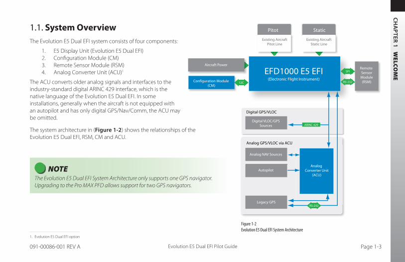
1.1. System OverviewThe Evolution E5 Dual EFI system consists of four components:
1. E5 Display Unit (Evolution E5 Dual EFI)2. Configuration Module (CM)3. Remote Sensor Module (RSM)4. Analog Converter Unit (ACU)1
The ACU converts older analog signals and interfaces to the industry-standard digital ARINC 429 interface, which is the native language of the Evolution E5 Dual EFI. In some installations, generally when the aircraft is not equipped with an autopilot and has only digital GPS/Nav/Comm, the ACU may be omitted.
The system architecture in (Figure 1-2) shows the relationships of the Evolution E5 Dual EFI, RSM, CM and ACU.
NOTE The Evolution E5 Dual EFI System Architecture only supports one GPS navigator. Upgrading to the Pro MAX PFD allows support for two GPS navigators.
Digital GPS/VLOC
Analog GPS/VLOC via ACU
EFD1000 E5 EFI(Electronic Flight Instrument)
Analog Converter Unit
(ACU)
Aircraft Power
Configuration Module (CM)
12C
SPI
RS-232
Digital VLOC/GPSSources
Analog NAV Sources
Autopilot
Legacy GPSRS-232
Pitot Static
Existing AircraftStatic Line
Existing AircraftPitot Line
Remote SensorModule(RSM)
ARINC 429
Figure 1-2 Evolution E5 Dual EFI System Architecture
1. Evolution E5 Dual EFI option
CH
AP
TER
1
WEL
CO
ME
Evolution E5 Dual EFI Pilot GuidePage 1-4 091-00086-001 REV A
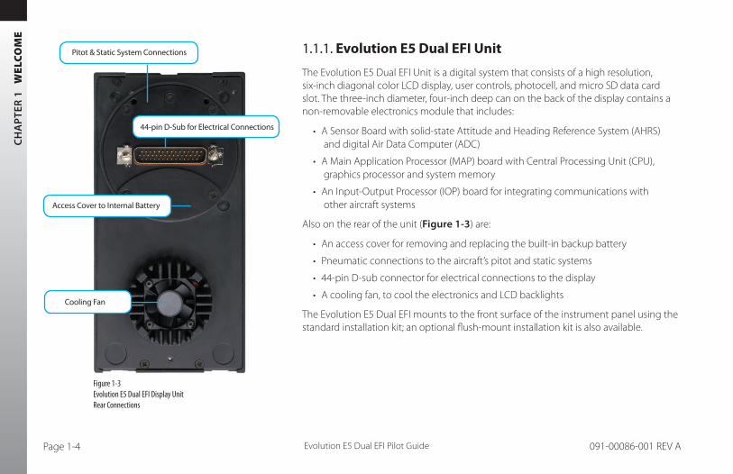
1.1.1. Evolution E5 Dual EFI Unit
The Evolution E5 Dual EFI Unit is a digital system that consists of a high resolution, six-inch diagonal color LCD display, user controls, photocell, and micro SD data card slot. The three-inch diameter, four-inch deep can on the back of the display contains a non-removable electronics module that includes:
• A Sensor Board with solid-state Attitude and Heading Reference System (AHRS) and digital Air Data Computer (ADC)
• A Main Application Processor (MAP) board with Central Processing Unit (CPU), graphics processor and system memory
• An Input-Output Processor (IOP) board for integrating communications with other aircraft systems
Also on the rear of the unit (Figure 1-3) are:
• An access cover for removing and replacing the built-in backup battery
• Pneumatic connections to the aircraft’s pitot and static systems
• 44-pin D-sub connector for electrical connections to the display
• A cooling fan, to cool the electronics and LCD backlights
The Evolution E5 Dual EFI mounts to the front surface of the instrument panel using the standard installation kit; an optional flush-mount installation kit is also available.
Figure 1-3 Evolution E5 Dual EFI Display Unit Rear Connections
44-pin D-Sub for Electrical Connections
Access Cover to Internal Battery
Pitot & Static System Connections
Cooling Fan

CH
AP
TER 1 W
ELCO
ME
Evolution E5 Dual EFI Pilot Guide Page 1-5091-00086-001 REV A
1.1.2. Configuration Module (CM)
The Configuration Module (Figure 1-4), contains an EEPROM device that retains system configuration and calibration data and provides two primary functions:
• Retains aircraft-specific configuration information, calibration data, and user settings, allowing the Evolution E5 Dual EFI to be swapped for service purposes without re-entering or re-calibrating the installation
• Contains a license key that configures the Evolution E5 Dual EFI software features
The CM is typically attached to the wire bundle coming out of the D-sub connector on the display unit.
1.1.3. Analog Converter Unit (ACU)1
The Analog Converter Unit (ACU) (Figure 1-5), is highly recommended if you are considering upgrading your E5 to a Pro MAX PFD. It enables the all-digital, EFD1000 System to interface with analog avionics when required. The ACU converts multiple analog interfaces to the digital ARINC 429 buses supported by the Evolution E5 Dual EFI. Control parameters, such as desired heading, are also sent from the Evolution E5 Dual EFI to the ACU for conversion to analog format for autopilot support. The ACU is required when any of the following capabilities are required in a EFI installation:
• Interface to supported autopilots• Interface to conventional VHF navigation radios• Interface to legacy (non-ARINC 429) GPS navigators
If ARINC 429-based digital radios, such as the Garmin 400/500-series GPS/nav/comm radios are installed in the aircraft and no other aircraft interfaces are desired, the ACU is not required.
Figure 1-4 Configuration Module (CM)
Figure 1-5Analog Converter Unit (ACU)
1. Evolution E5 Dual EFI Unit option
CH
AP
TER
1
WEL
CO
ME
Evolution E5 Dual EFI Pilot GuidePage 1-6 091-00086-001 REV A
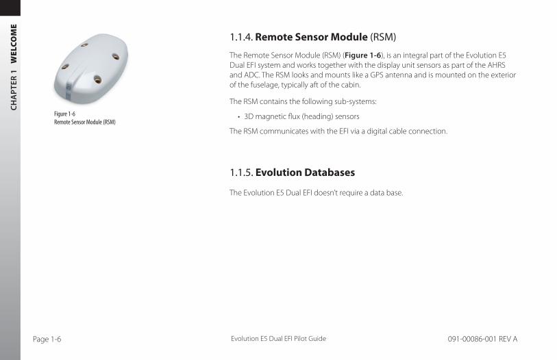
1.1.4. Remote Sensor Module (RSM)
The Remote Sensor Module (RSM) (Figure 1-6), is an integral part of the Evolution E5 Dual EFI system and works together with the display unit sensors as part of the AHRS and ADC. The RSM looks and mounts like a GPS antenna and is mounted on the exterior of the fuselage, typically aft of the cabin.
The RSM contains the following sub-systems:
• 3D magnetic flux (heading) sensors
The RSM communicates with the EFI via a digital cable connection.
1.1.5. Evolution Databases
The Evolution E5 Dual EFI doesn’t require a data base.
Figure 1-6Remote Sensor Module (RSM)

CH
AP
TER 2 C
ON
TR
OLS
AN
D D
ISP
LAY
Evolution E5 Dual EFI Pilot Guide Page 2-1091-00086-001 REV A
Chapter 2Controls and Display
The Evolution E5 Dual EFI is a flat-panel LCD elctronic flight instrument that presents the pilot with all of the information from the traditional six-pack of mechanical instruments: Airspeed, Attitude, Altitude, Turn Coordinator, Heading Indicator and Vertical Speed Indicator (VSI).
The Evolution E5 Dual EFI is a single vertical instrument that replaces the existing Attitude Indicator and Heading Indicator. The display is divided into three parts: an upper Attitude Display, a lower Navigation Display, and a Data Bar between the upper and lower halves.
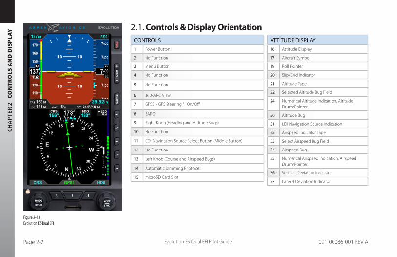
This chapter gives an overview of all the instruments, information, and controls of the Evolution E5 Dual EFI. Table 2-1 and (Figure 2-2) identify the controls and display orientation (see Chapter 4, Reference Guide for more details).
Figure 2-1Evolution E5 Dual EFI
CH
AP
TER
2
CO
NT
RO
LS A
ND
DIS
PLA
Y
Evolution E5 Dual EFI Pilot GuidePage 2-2 091-00086-001 REV A
2.1. Controls & Display Orientation ATTITUDE DISPLAY
16 Attitude Display
17 Aircraft Symbol
19 Roll Pointer
20 Slip/Skid Indicator
21 Altitude Tape
22 Selected Altitude Bug Field
24 Numerical Altitude Indication, Altitude Drum/Pointer
26 Altitude Bug
31 LDI Navigation Source Indication
32 Airspeed Indicator Tape
33 Select Airspeed Bug Field
34 Airspeed Bug
35 Numerical Airspeed Indication, Airspeed Drum/Pointer
36 Vertical Deviation Indicator
37 Lateral Deviation Indicator
CONTROLS
1 Power Button
2 No Function
3 Menu Button
4 No Function
5 No Function
6 360/ARC View
7 GPSS - GPS Steering 1 On/Off
8 BARO
9 Right Knob (Heading and Altitude Bugs)
10 No Function
11 CDI Navigation Source Select Button (Middle Button)
12 No Function
13 Left Knob (Course and Airspeed Bugs)
14 Automatic Dimming Photocell
15 microSD Card Slot
Figure 2-1aEvolution E5 Dual EFI

CH
AP
TER 2 C
ON
TR
OLS
AN
D D
ISP
LAY
Evolution E5 Dual EFI Pilot Guide Page 2-3091-00086-001 REV A
DATA BAR
38 Ture Airspeed (TAS)
39 Barometric Pressure Setting Field
40 Wind Direction and Speed
41 Wind Direction Arrow
42 Outside Air Temperature (OAT)
43 Ground Speed (GS)
NAVIGATION DISPLAY
44 Navigation Display
45 Ownship Symbol
46 Course Pointer
47 TO/FROM Indicator
48 Rate of Turn Indicator
49 Track Marker
50 Magnetic Heading
51 Selection Course (CRS) Field
52 Selected Heading (HDG) Field
53 Heading Bug
54 Course Deviation Scale
55 Course Deviation Indicator
56 Vertical Speed Digital Value
57 Vertical Speed Tape
64 CDI Navigation Source
66 Left Knob State
67 Right Knob State
68 Hot Key Legend
Figure 2-2 Evolution E5 Dual EFI Display Elements
Table 2-1 Evolution E5 Dual EFI Display Elements
1. With compatible autopilots
15
12 13
5143
34
38
53
46 4948
47
54
45
55
44
33 22
3742 41 40
32
35 24
16
2019
26
21
39
36
31
57
29
17
52 56
9
8
7
6
5
4
3
2
1
14
66 64 67
11 10
50
68
NOTE Data Bar features of TAS, Winds, and OAT are only presented when enabled.

CH
AP
TER
2
CO
NT
RO
LS A
ND
DIS
PLA
Y
Evolution E5 Dual EFI Pilot GuidePage 2-4 091-00086-001 REV A
2.2. ControlsThe primary means for the pilot to control the Evolution E5 Dual EFI are the two knobs and center button at the bottom of the display. The knobs control setting CRS and HDG, and additional bugs and altitude settings. The lower center button control selection of navigation sources for the CDI. There are center button controls above the Hot Keys to control entering and exiting the Menu and Reversion or Manual Power Control.
Five Hot Keys to the right of the Navigation Display toggle various features on and off. The function of each is indicated by the label on the display to the left of each key.
2.2.1. Left and Right Knobs
The Left and Right Knobs are designed to provide immediate operation yet minimize the possibility of an inadvertent operation. This is accomplished by requiring that the first action of the knob “wakes up” the knob and changes the label from cyan to magenta. The first click when the knob is turned or the first press on the knob, “wakes up” the knob function.
Press the knob more than once to cycle through its Menu options in a round-robin sequence or press and hold the knob to synchronize (SYNC) the function’s value (see Section 2.2.1.3. SYNC Function). After 10 seconds of inactivity, the knob returns to its default setting.
CH
AP
TER 2 C
ON
TR
OLS
AN
D D
ISP
LAY
Evolution E5 Dual EFI Pilot Guide Page 2-5091-00086-001 REV A
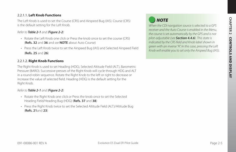
2.2.1.1. Left Knob Functions
The Left Knob is used to set the Course (CRS) and Airspeed Bug (IAS). Course (CRS) is the default setting for the Left Knob.
Refer to Table 2-1 and (Figure 2-2)
• Rotate the Left Knob one click or Press the knob once to set the course (CRS) (Refs. 32 and 36 and see NOTE about Auto Course)
• Press the Left Knob twice to set the Airspeed Bug (IAS) and Selected Airspeed Field
(Refs. 25 and 26)
2.2.1.2. Right Knob Functions
The Right Knob is used to set Heading (HDG), Selected Altitude Field (ALT), Barometric Pressure (BARO). Successive presses of the Right Knob will cycle through HDG and ALT in a round-robin sequence. Rotate the Right Knob to the left or right to decrease or increase the value of selected field. Heading (HDG) is the default setting for the Right Knob.
Refer to Table 2-1 and (Figure 2-2)
• Rotate the Right Knob one click or Press the knob once to set the Selected Heading Field/Heading Bug (HDG) (Refs. 37 and 38)
• Press the Right Knob twice to set the Selected Altitude Field (ALT)/Altitude Bug (Refs. 21and 23)
NOTE When the CDI navigation source is selected to a GPS receiver and the Auto Course is enabled in the Menu, the course is set automatically by the GPS and is not pilot-adjustable (see Section 4.4.6). This state is indicated by the CRS field and Knob label shown in green with an inverse “A”. In this case, pressing the Left Knob will enable you to set only the Airspeed Bug (IAS).
CH
AP
TER
2
CO
NT
RO
LS A
ND
DIS
PLA
Y
Evolution E5 Dual EFI Pilot GuidePage 2-6 091-00086-001 REV A
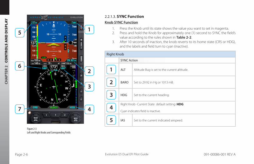
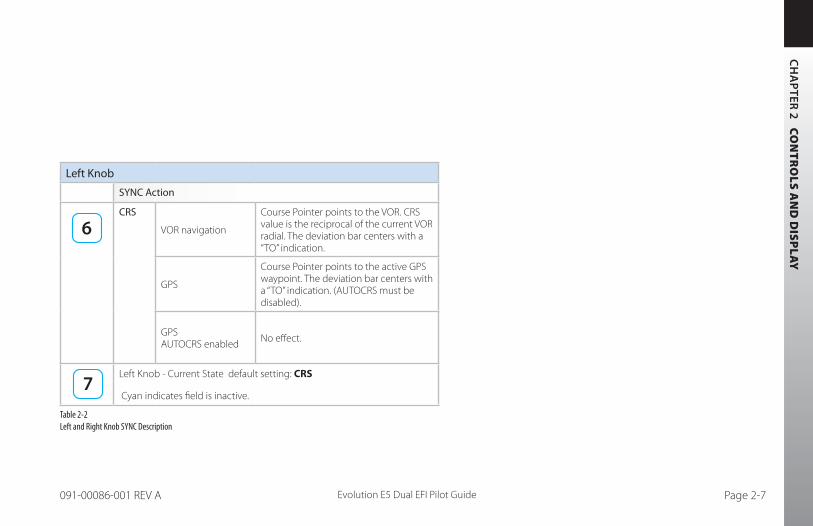
2.2.1.3. SYNC FunctionKnob SYNC Function
1. Press the Knob until its state shows the value you want to set in magenta.2. Press and hold the Knob for approximately one (1) second to SYNC the field’s
value according to the rules shown in Table 2-2.3. After 10 seconds of inaction, the knob reverts to its home state (CRS or HDG),
and the labels and field turn to cyan (inactive).
Right Knob
SYNC Action
ALT Altitude Bug is set to the current altitude.
BARO Set to 29.92 in Hg or 1013 mB.
HDG Set to the current heading.
Right Knob -Current State default setting: HDG
Cyan indicates field is inactive.
IAS Set to the current indicated airspeed.
Figure 2-3 Left and Right Knobs and Corresponding Fields
CH
AP
TER 2 C
ON
TR
OLS
AN
D D
ISP
LAY
Evolution E5 Dual EFI Pilot Guide Page 2-7091-00086-001 REV A
Left Knob
SYNC Action
CRS
VOR navigation
Course Pointer points to the VOR. CRS value is the reciprocal of the current VOR radial. The deviation bar centers with a “TO” indication.
GPS
Course Pointer points to the active GPS waypoint. The deviation bar centers with a “TO” indication. (AUTOCRS must be disabled).
GPS AUTOCRS enabled No effect.
Left Knob - Current State default setting: CRS
Cyan indicates field is inactive.
Table 2-2 Left and Right Knob SYNC Description

CH
AP
TER
2
CO
NT
RO
LS A
ND
DIS
PLA
Y
Evolution E5 Dual EFI Pilot GuidePage 2-8 091-00086-001 REV A
Figure 2-4 Editing the HDG field
Figure 2-5 HDG field updated and inactive
2.2.1.4. Using the Knobs (Example)
How to Set the Heading Bug (HDG)
1. Rotate the Right Knob to the desired heading value, shown both by the position of the Heading Bug and the numeric value in the Selected Heading Field (Figure 2-4). The HDG label, Heading Bug and the Selected Heading Field appears in magenta
2. After 10 seconds of inactivity, the knob defaults to HDG. The HDG label, Heading Bug and Selected Heading Field value will appear in cyan (Figure 2-5).
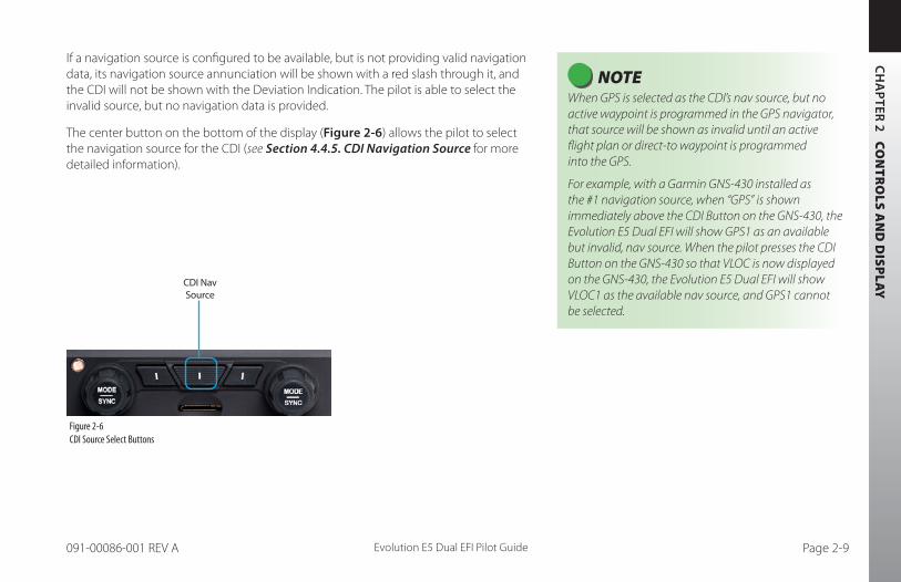
2.2.2. Navigation Source Select Buttons
The center button on the bottom of the display (Figure 2-6) allow the pilot to select the navigation source for the CDI (see Section 4.4.5. CDI Navigation Source for more detailed information).
The CDI Nav Source Select Button is the center button (Figure 2-6). It selects which of the available navigation sources will couple to the CDI, which in turn couples to the autopilot (if available). Each press of the CDI Nav Source Button selects the next available nav source, cycling through all available sources in a round-robin sequence. The currently coupled CDI nav source is displayed directly above the CDI Nav Source Select Button.
The available navigation sources are configured when the Evolution E5 Dual EFI was installed (depending on what is installed in the aircraft and connected to the Evolution E5 Dual EFI). The available navigation source choices are: GPS1and VLOC1.
CH
AP
TER 2 C
ON
TR
OLS
AN
D D
ISP
LAY
Evolution E5 Dual EFI Pilot Guide Page 2-9091-00086-001 REV A
If a navigation source is configured to be available, but is not providing valid navigation data, its navigation source annunciation will be shown with a red slash through it, and the CDI will not be shown with the Deviation Indication. The pilot is able to select the invalid source, but no navigation data is provided.
The center button on the bottom of the display (Figure 2-6) allows the pilot to select the navigation source for the CDI (see Section 4.4.5. CDI Navigation Source for more detailed information).
NOTE When GPS is selected as the CDI’s nav source, but no active waypoint is programmed in the GPS navigator, that source will be shown as invalid until an active flight plan or direct-to waypoint is programmed into the GPS.
For example, with a Garmin GNS-430 installed as the #1 navigation source, when “GPS” is shown immediately above the CDI Button on the GNS-430, the Evolution E5 Dual EFI will show GPS1 as an available but invalid, nav source. When the pilot presses the CDI Button on the GNS-430 so that VLOC is now displayed on the GNS-430, the Evolution E5 Dual EFI will show VLOC1 as the available nav source, and GPS1 cannot be selected.
Figure 2-6 CDI Source Select Buttons
CDI Nav Source

CH
AP
TER
2
CO
NT
RO
LS A
ND
DIS
PLA
Y
Evolution E5 Dual EFI Pilot GuidePage 2-10 091-00086-001 REV A
2.2.3. Hot Keys
The five keys along the lower right side of the Evolution E5 Dual EFI function as either single-action Hot Keys for frequently used commands or as Menu Keys when the Menu has been activated. The Hot Key functions are accessible at any time, except when the Menu is active.
Each Hot Key provides instant access to the assigned command. Each press of a Hot Key toggles between the settings that each key controls (see Table 2-3).
The Hot Key labels use the following color philosophy (see Figure 2-7).
• A green label and dark blue letters (also known as inverse green) indicates that the Hot Key function is enabled
• A dark blue label and green letters indicates that the Hot Key function is disabled
• A dark blue label and gray letters indicates that the Hot Key function is not available
• A dark blue label without letters indicates that the Hot Key has no function
The 360/ARC Hot Key labels indicate which mode is currently active on the Navigation Display.

CH
AP
TER 2 C
ON
TR
OLS
AN
D D
ISP
LAY
Evolution E5 Dual EFI Pilot Guide Page 2-11091-00086-001 REV A
Figure 2-7 Hot Key Menu
HOT KEY DESCRIPTION OPTIONS
No Function
No Function
360°/ ARCToggles between 360° and ARC modes of Navigation Display (see Section 4.4.1.)
360 360° Compass Mode
ARC ARC Compass Mode
GPSSToggles between GPS Steering (GPSS) Mode and HDG mode for Autopilot
GPSS GPSS on
GPSS GPSS Off, HDG mode active
BAROToggles between BARO adjustment on or off for Barometric Pressure setting
BARO BARO adjustment on
BARO BARO adjustment off
Table 2-3 Hot Key Descriptions

CH
AP
TER
2
CO
NT
RO
LS A
ND
DIS
PLA
Y
Evolution E5 Dual EFI Pilot GuidePage 2-12 091-00086-001 REV A
2.2.4. Menu
The MENU button is used to access the Evolution E5 Dual EFI’s Menu to change options, and also to change the display brightness.
2.2.4.1. Using the Menus
Press the MENU button to activate the Menu (Ref. 3). The current menu page name is shown on the bottom center of the Navigation Display. Directly below the menu page name is a segmented menu page bar, giving a graphical representation of the current page relative to the total number of menu pages. The current menu page number is shown in the lower right corner of the Navigation Display.
Menu Page 1, General Settings is the one most commonly used in flight. It allows the pilot to enable or disable airspeed and altitude tapes, BARO, GPS Autocourse and conduct AHRS resets. The other menu pages are used for Vspeeds and map customization, Evolution E5 Dual EFI power management, product version information, and information and option settings, relative to your specific equipment and installed options.
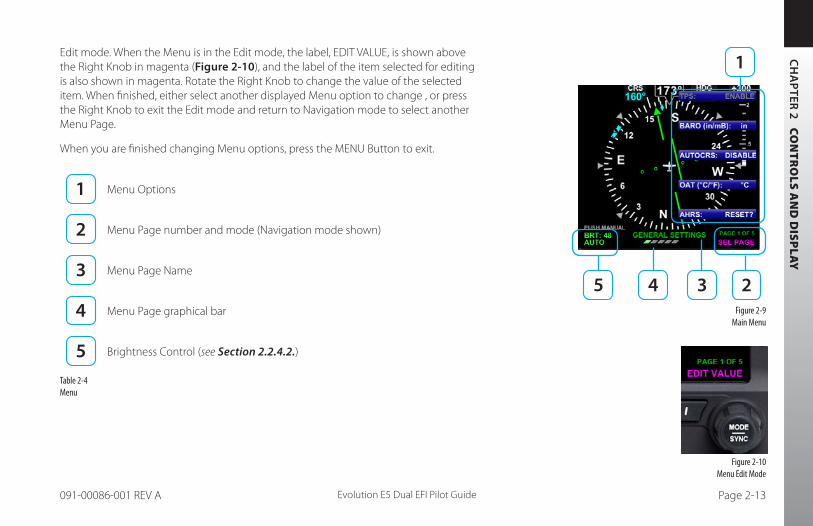
The Menu operates either in the Navigation or Edit mode, as indicated by the label directly above the Right Knob. When the MENU button is first pressed, the Main Menu is in the Navigation mode, indicated by the magenta label SEL PAGE directly above the Right Knob (Figure 2-8). When in the Navigation mode, rotating the Right Knob navigates through the menu pages. Rotate the Right Knob clockwise to advance to the next menu page, counterclockwise to return to the previous page.
Each Menu Page has up to five selectable options, each adjacent to one of the five Hot Keys which double as Menu Keys when the Menu is active (Item 1 of Figure 2-9 and Table 2-4). After navigating to the Menu Page containing the option you want to change, press the Menu Key adjacent to that option label, which initiates the Menu’s
Figure 2-8 Menu Navigation Mode
CH
AP
TER 2 C
ON
TR
OLS
AN
D D
ISP
LAY
Evolution E5 Dual EFI Pilot Guide Page 2-13091-00086-001 REV A
Figure 2-10 Menu Edit Mode
Figure 2-9 Main Menu
Edit mode. When the Menu is in the Edit mode, the label, EDIT VALUE, is shown above the Right Knob in magenta (Figure 2-10), and the label of the item selected for editing is also shown in magenta. Rotate the Right Knob to change the value of the selected item. When finished, either select another displayed Menu option to change , or press the Right Knob to exit the Edit mode and return to Navigation mode to select another Menu Page.
When you are finished changing Menu options, press the MENU Button to exit.
Menu Options
Menu Page number and mode (Navigation mode shown)
Menu Page Name
Menu Page graphical bar
Brightness Control (see Section 2.2.4.2.)
Table 2-4 Menu

CH
AP
TER
2
CO
NT
RO
LS A
ND
DIS
PLA
Y
Evolution E5 Dual EFI Pilot GuidePage 2-14 091-00086-001 REV A
The MENU text will display in one of the four colors listed and described in Table 2-5.
DISPLAY TEXT
DESCRIPTION DISPLAY
WHITE Editable option Figure 2-11
MAGENTA Editable option enabled Figure 2-12
GREEN Status Only Figure 2-13
GRAY Disabled (Not available for selection or editing) Figure 2-14
Table 2-5Menu Text
NOTE These steps are provided as a basic overview. Each menu command is covered in detail in Chapter 5.
Access To and Navigation Within the Menu
1. Press the MENU button. The Menu displays on the Navigation Display adjacent to the Hot Keys (Figure 2-15).
2. Rotate the Right Knob to navigate through the different pages of the Menu. Rotating the Right Knob clockwise advances the Menu Pages, counterclockwise returns to previous pages.
3. Press the MENU Button to exit.Figure 2-15 Menu Display
Figure 2-11 Menu Text - Editable
Figure 2-12 Menu Text - Enabled for Editing
Figure 2-13 Menu Text - Status Only
Figure 2-14 Menu Text - Disabled
CH
AP
TER 2 C
ON
TR
OLS
AN
D D
ISP
LAY
Evolution E5 Dual EFI Pilot Guide Page 2-15091-00086-001 REV A
Figure 2-16 EDIT VALUE Displays Above Right Knob
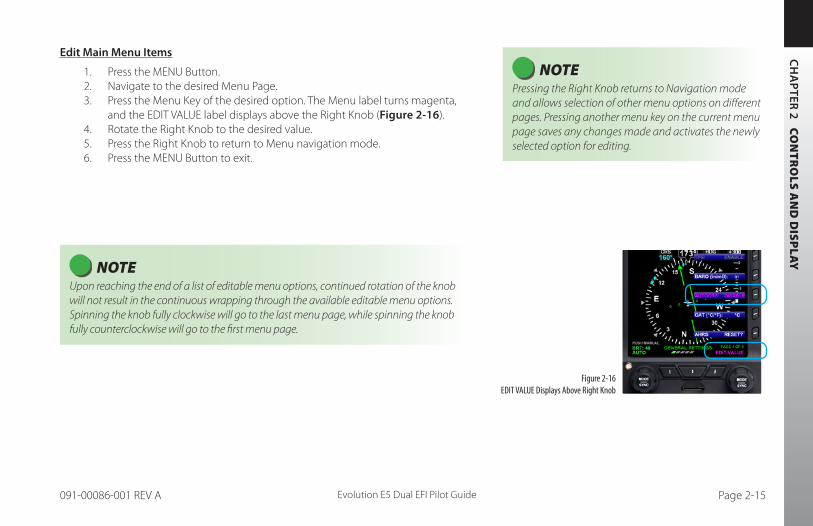
NOTE Pressing the Right Knob returns to Navigation mode and allows selection of other menu options on different pages. Pressing another menu key on the current menu page saves any changes made and activates the newly selected option for editing.
Edit Main Menu Items
1. Press the MENU Button.2. Navigate to the desired Menu Page.3. Press the Menu Key of the desired option. The Menu label turns magenta,
and the EDIT VALUE label displays above the Right Knob (Figure 2-16).4. Rotate the Right Knob to the desired value.5. Press the Right Knob to return to Menu navigation mode.6. Press the MENU Button to exit.
NOTE Upon reaching the end of a list of editable menu options, continued rotation of the knob will not result in the continuous wrapping through the available editable menu options. Spinning the knob fully clockwise will go to the last menu page, while spinning the knob fully counterclockwise will go to the first menu page.
CH
AP
TER
2
CO
NT
RO
LS A
ND
DIS
PLA
Y
Evolution E5 Dual EFI Pilot GuidePage 2-16 091-00086-001 REV A
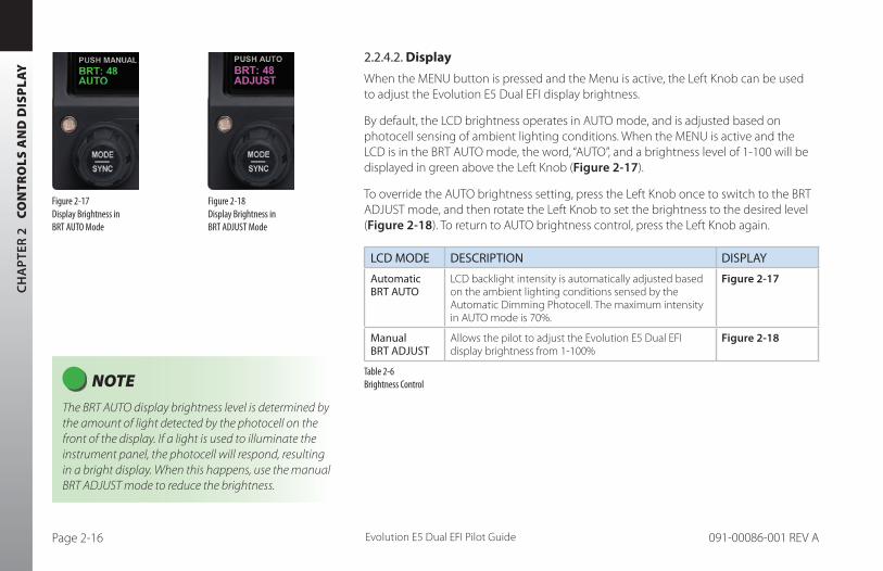
2.2.4.2. Display
When the MENU button is pressed and the Menu is active, the Left Knob can be used to adjust the Evolution E5 Dual EFI display brightness.
By default, the LCD brightness operates in AUTO mode, and is adjusted based on photocell sensing of ambient lighting conditions. When the MENU is active and the LCD is in the BRT AUTO mode, the word, “AUTO”, and a brightness level of 1-100 will be displayed in green above the Left Knob (Figure 2-17).
To override the AUTO brightness setting, press the Left Knob once to switch to the BRT ADJUST mode, and then rotate the Left Knob to set the brightness to the desired level (Figure 2-18). To return to AUTO brightness control, press the Left Knob again.
LCD MODE DESCRIPTION DISPLAY
Automatic BRT AUTO
LCD backlight intensity is automatically adjusted based on the ambient lighting conditions sensed by the Automatic Dimming Photocell. The maximum intensity in AUTO mode is 70%.
Figure 2-17
Manual BRT ADJUST
Allows the pilot to adjust the Evolution E5 Dual EFI display brightness from 1-100%
Figure 2-18
Table 2-6 Brightness Control
Figure 2-17 Display Brightness in BRT AUTO Mode
Figure 2-18 Display Brightness in BRT ADJUST Mode
NOTE The BRT AUTO display brightness level is determined by the amount of light detected by the photocell on the front of the display. If a light is used to illuminate the instrument panel, the photocell will respond, resulting in a bright display. When this happens, use the manual BRT ADJUST mode to reduce the brightness.

CH
AP
TER 2 C
ON
TR
OLS
AN
D D
ISP
LAY
Evolution E5 Dual EFI Pilot Guide Page 2-17091-00086-001 REV A
2.2.5. Range Buttons
Range Buttons have no function on the Evolution E5 Dual EFI.
2.2.6. REV Button
The red REV Button on the Evolution E5 Dual EFI can be used to override automatic power control in abnormal or emergency situations (see Chapter 6, Section 6.4. and Figure 6-29 for more details).
CH
AP
TER
2
CO
NT
RO
LS A
ND
DIS
PLA
Y
Evolution E5 Dual EFI Pilot GuidePage 2-18 091-00086-001 REV A
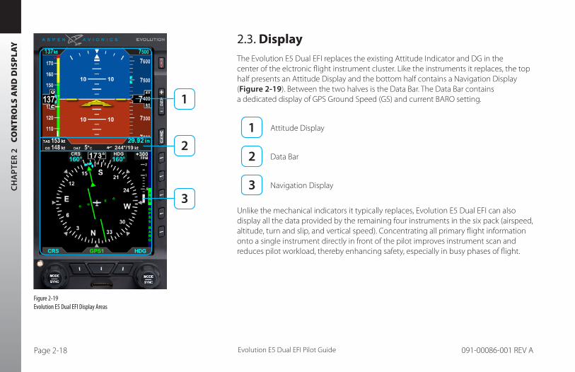
2.3. DisplayThe Evolution E5 Dual EFI replaces the existing Attitude Indicator and DG in the center of the elctronic flight instrument cluster. Like the instruments it replaces, the top half presents an Attitude Display and the bottom half contains a Navigation Display (Figure 2-19). Between the two halves is the Data Bar. The Data Bar contains a dedicated display of GPS Ground Speed (GS) and current BARO setting.
Attitude Display
Data Bar
Navigation Display
Unlike the mechanical indicators it typically replaces, Evolution E5 Dual EFI can also display all the data provided by the remaining four instruments in the six pack (airspeed, altitude, turn and slip, and vertical speed). Concentrating all primary flight information onto a single instrument directly in front of the pilot improves instrument scan and reduces pilot workload, thereby enhancing safety, especially in busy phases of flight.
Figure 2-19 Evolution E5 Dual EFI Display Areas

CH
AP
TER 2 C
ON
TR
OLS
AN
D D
ISP
LAY
Evolution E5 Dual EFI Pilot Guide Page 2-19091-00086-001 REV A
CAUTION Use caution when using isopropyl alcohol as it is flammable. Using any other chemicals or materials voids the warranty.
The Evolution E5 Dual EFI generally follows standard display conventions for Electronic Flight Instrument Systems (EFIS), so a pilot with some experience and familiarity with other EFIS displays will usually transition quickly to using the Evolution E5 Dual EFI. Pilots for whom the Evolution E5 Dual EFI is their first real exposure to EFIS and glass cockpit flying, however, should get some transition training from a certified flight instructor (CFI) with EFIS experience. Pilots are also encouraged to study some of the excellent publications and training videos now available to help with the transition.
This section gives an overview of the main display elements and features. (see Chapter 4, Reference Guide for more details).
2.3.1. Cleaning the Display Screen
The Display Unit has an LCD screen that is prone to damage from scratches, smudging, and clouding caused by the use of improper cleaning agents and abrasive cloths. Exercise care when cleaning, using the following tips:
• Only clean the display when the it is off.
• Use a clean, soft, lint-free cloth dampened with a 50/50 solution of isopropyl alcohol and water, a pre-moistened lens cleaning tissue, such as Bausch & Lomb Sight Savers®, or a cleaning solution made especially for LCD displays.
• Never spray any cleaning solutions directly onto the screen; spray it into the cleaning cloth.
• Gently wipe the screen in a circular motion. Do not press hard on the screen.
• Remove all excess moisture to prevent damage to the display.
• The display should be dry before turning on the Evolution E5 Dual EFI.
CH
AP
TER
2
CO
NT
RO
LS A
ND
DIS
PLA
Y
Evolution E5 Dual EFI Pilot GuidePage 2-20 091-00086-001 REV A
2.3.2. Attitude Display
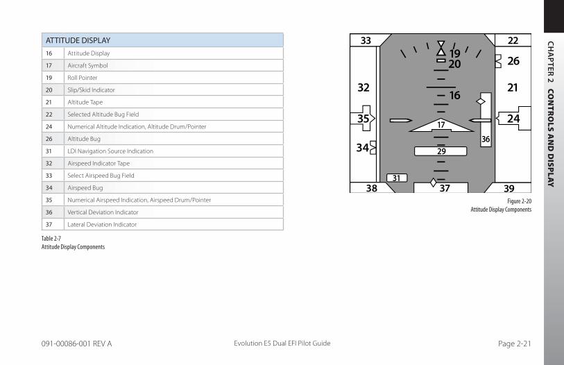
The Attitude Display includes an Attitude Indicator, an Airspeed tape, an Altimeter tape, and course and glide slope indicators (Table 2-7 and Figure 2-20), (see Chapter 4, Reference Guide for more details).
The Airspeed and Altitude tapes are common on most EFIS displays and will be immediately familiar to pilots with EFIS experience.
Transitioning pilots can use either their familiar mechanical instruments. Should the tapes prove distracting, the pilot can remove them from the display by disabling them in the Menu. (Page 1, GENERAL SETTINGS.
CH
AP
TER 2 C
ON
TR
OLS
AN
D D
ISP
LAY
Evolution E5 Dual EFI Pilot Guide Page 2-21091-00086-001 REV A
Figure 2-20 Attitude Display Components
ATTITUDE DISPLAY
16 Attitude Display
17 Aircraft Symbol
19 Roll Pointer
20 Slip/Skid Indicator
21 Altitude Tape
22 Selected Altitude Bug Field
24 Numerical Altitude Indication, Altitude Drum/Pointer
26 Altitude Bug
31 LDI Navigation Source Indication
32 Airspeed Indicator Tape
33 Select Airspeed Bug Field
34 Airspeed Bug
35 Numerical Airspeed Indication, Airspeed Drum/Pointer
36 Vertical Deviation Indicator
37 Lateral Deviation Indicator
Table 2-7 Attitude Display Components
15
12 13
5143
34
38
53
46 4948
47
54
45
55
44
33 22
3742 41 40
32
35 24
16
2019
26
21
39
36
31
57
29
17
52 56
9
8
7
6
5
4
3
2
1
14
66 64 67
11 10
50
68
CH
AP
TER
2
CO
NT
RO
LS A
ND
DIS
PLA
Y
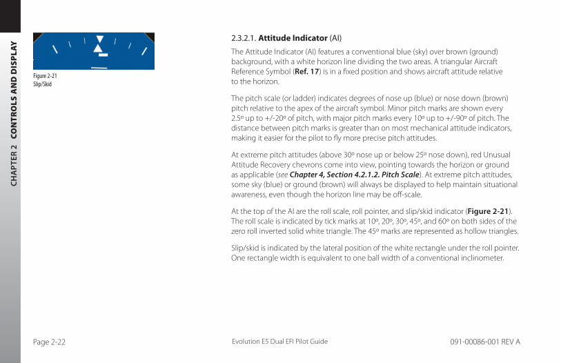
Evolution E5 Dual EFI Pilot GuidePage 2-22 091-00086-001 REV A
2.3.2.1. Attitude Indicator (AI)
The Attitude Indicator (AI) features a conventional blue (sky) over brown (ground) background, with a white horizon line dividing the two areas. A triangular Aircraft Reference Symbol (Ref. 17) is in a fixed position and shows aircraft attitude relative to the horizon.
The pitch scale (or ladder) indicates degrees of nose up (blue) or nose down (brown) pitch relative to the apex of the aircraft symbol. Minor pitch marks are shown every 2.5º up to +/-20º of pitch, with major pitch marks every 10º up to +/-90º of pitch. The distance between pitch marks is greater than on most mechanical attitude indicators, making it easier for the pilot to fly more precise pitch attitudes.
At extreme pitch attitudes (above 30º nose up or below 25º nose down), red Unusual Attitude Recovery chevrons come into view, pointing towards the horizon or ground as applicable (see Chapter 4, Section 4.2.1.2. Pitch Scale). At extreme pitch attitudes, some sky (blue) or ground (brown) will always be displayed to help maintain situational awareness, even though the horizon line may be off-scale.
At the top of the AI are the roll scale, roll pointer, and slip/skid indicator (Figure 2-21). The roll scale is indicated by tick marks at 10º, 20º, 30º, 45º, and 60º on both sides of the zero roll inverted solid white triangle. The 45º marks are represented as hollow triangles.
Slip/skid is indicated by the lateral position of the white rectangle under the roll pointer. One rectangle width is equivalent to one ball width of a conventional inclinometer.
Figure 2-21 Slip/Skid

CH
AP
TER 2 C
ON
TR
OLS
AN
D D
ISP
LAY
Evolution E5 Dual EFI Pilot Guide Page 2-23091-00086-001 REV A
Figure 2-22 Airspeed Tape
2.3.2.2. Airspeed Tape and Bug
Airspeed is indicated by a moving airspeed tape against a fixed position airspeed pointer, shown on the left-hand side of the Attitude Display (Figure 2-22). A numerical, rolling drum readout indicating airspeed values to the closest one knot or mile per hour is provided adjacent to the fixed pointer. Tick marks are provided on the airspeed tape every 10 knots (or mph, if so configured). Airspeeds between 20 kts (23 mph) to 450 kts (518 mph) are displayed. Outside of this range, the airspeed value is dashed.
Color speed bands are displayed on the indicated airspeed tape, corresponding to the color arcs found on a mechanical airspeed indicator.
Color speed markers are also displayed on the indicated airspeed tape, corresponding to the markers found on traditional airspeed indicators. All aircraft have a red line for aircraft never-exceed speed (Vne). If the aircraft manufacturer has published an initial flap extension speed, a white triangle will be presented on the airspeed tape at this speed.
Textual Vspeed markers can also be shown on the airspeed tape (e.g., Vx, Vy, Va, etc.). These are typically programmed at installation, and (if left unlocked during installation) may also be adjusted by the pilot. Vspeed display can be enabled or disabled by the pilot from Page 1 of the Menu (see Chapter 5).

CH
AP
TER
2
CO
NT
RO
LS A
ND
DIS
PLA
Y
Evolution E5 Dual EFI Pilot GuidePage 2-24 091-00086-001 REV A
The pilot can set a target airspeed using the Left Knob (see Section 4.2.2.1.). The target airspeed is shown on the Airspeed Tape as an Airspeed Bug with its setting displayed numerically above the Airspeed Tape. The Airspeed Bug and numerical value are for visual reference only, to help the pilot maintain a target airspeed; there is no alerting for deviations from the target.
2.3.2.3. Altitude Tape
Altitude is indicated by a moving altitude tape against a fixed position altitude pointer (Figure 2-2, No. 20, 22), shown on the right-hand side of the Attitude Display (Figure 2-23). A numerical rolling drum readout indicating altitude values to the closest 20 feet is provided adjacent to the fixed pointer.
Minor tick marks are provided on the tape at 20-foot intervals, and major tick marks are provided at 100-foot intervals. The thousand and ten-thousand digits are larger than other digits on the tape. Negative altitudes are indicated by a “-“ sign preceding the numerical altitude value in the drum.
The current altimeter barometric pressure setting is shown just below the Altitude tape in the Data Bar (Figure 2-2, No. 28), and can be adjusted by pressing the BARO Hot Key and rotating the Right Knob.
Figure 2-23 Altitude Tape

CH
AP
TER 2 C
ON
TR
OLS
AN
D D
ISP
LAY
Evolution E5 Dual EFI Pilot Guide Page 2-25091-00086-001 REV A
2.3.3. Data Bar
The Data Bar visually separates the upper and lower halves of the display. GPS Ground Speed (GS) and Barometric Pressure Setting are presented in the Data Bar (Table 2-8 and Figure 2-24).
When any of these values are not available or invalid, the corresponding data field is dashed. When ground speed is not displayed, the “Degraded Mode” function is not available. A GPS navigator must be connected and providing valid ground speed and ground track to display GS.
The Data Bar is discussed in detail in Section 4.3.
DATA BAR
38 True Airspeed (TAS)
39 Barometric Pressure Setting Field
40 Wind Direction and Speed
41 Wind Direction Arrow
42 Outside Air Temperature (OAT)
43 Ground Speed (GS)
Table 2-8Data Bar Components
Figure 2-24 Data Bar Components
15
12 13
5143
34
38
53
46 4948
47
54
45
55
44
33 22
3742 41 40
32
35 24
16
2019
26
21
39
36
31
57
29
17
52 56
9
8
7
6
5
4
3
2
1
14
66 64 67
11 10
50
68
NOTE Data Bar features of TAS, Winds, and OAT are only presented when enabled.

CH
AP
TER
2
CO
NT
RO
LS A
ND
DIS
PLA
Y
Evolution E5 Dual EFI Pilot GuidePage 2-26 091-00086-001 REV A
2.3.4. Navigation Display
The lower half of the Evolution E5 Dual EFI is the Navigation Display (Table 2-9 and Figure 2-35), which shows a wide range of navigation information and flight data, including:
• Course Pointer and Heading Bug.
• 360° and ARC Compass rose display modes.
• Numeric displays of current magnetic heading, selected heading (HDG), and selected course (CRS).
• Ground Track Marker.
• Vertical Speed Indicator (VSI) tape and numerical rate value.
• Rate of Turn Indicator.
• Course Deviation Indicator (CDI).
• Navigation Source information.
• Caution annunciations for abnormal GPS status.

CH
AP
TER 2 C
ON
TR
OLS
AN
D D
ISP
LAY
Evolution E5 Dual EFI Pilot Guide Page 2-27091-00086-001 REV A
NAVIGATION DISPLAY
44 Navigation Display 53 Heading Bug
45 Ownship Symbol 54 Course Deviation Scale
46 Course Pointer 55 Course Deviation Indicator
47 TO/FROM Indicator 56 Vertical Speed Numerical Tape
48 Rate of Turn Indicator 57 Vertical Speed Indicator Tape
49 Ground Track Marker 64 Select CDI Navigation Source
50 Numerical Direction Indicator 66 Left Knob State
51 Selected Course (CRS) Field 67 Right Knob State
52 Selected Heading (HDG) Field 68 Hot Key Legend
Table 2-9 Navigation Display Components
Figure 2-25 Navigation Display Components
15
12 13
5143
34
38
53
46 4948
47
54
45
55
44
33 22
3742 41 40
32
35 24
16
2019
26
21
39
36
31
57
29
17
52 56
9
8
7
6
5
4
3
2
1
14
66 64 67
11 10
50
68
CH
AP
TER
2
CO
NT
RO
LS A
ND
DIS
PLA
Y
Evolution E5 Dual EFI Pilot GuidePage 2-28 091-00086-001 REV A
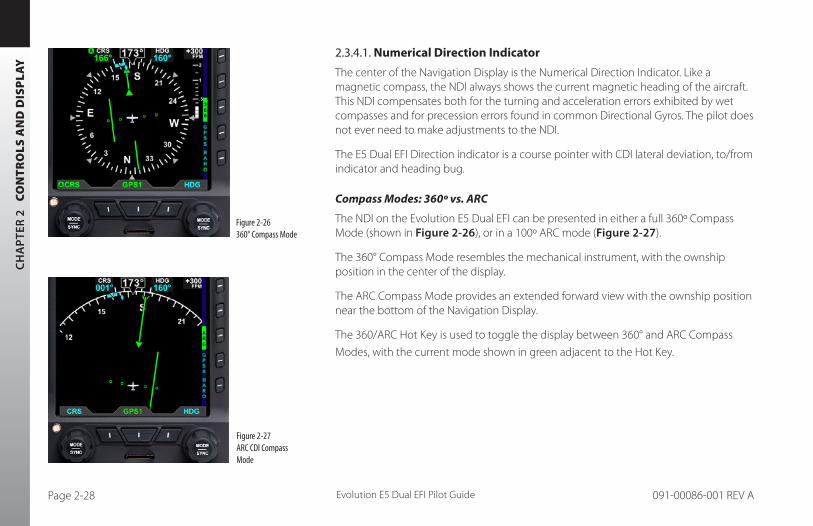
2.3.4.1. Numerical Direction Indicator
The center of the Navigation Display is the Numerical Direction Indicator. Like a magnetic compass, the NDI always shows the current magnetic heading of the aircraft. This NDI compensates both for the turning and acceleration errors exhibited by wet compasses and for precession errors found in common Directional Gyros. The pilot does not ever need to make adjustments to the NDI.
The E5 Dual EFI Direction indicator is a course pointer with CDI lateral deviation, to/from indicator and heading bug.
Compass Modes: 360º vs. ARC
The NDI on the Evolution E5 Dual EFI can be presented in either a full 360º Compass Mode (shown in Figure 2-26), or in a 100º ARC mode (Figure 2-27).
The 360° Compass Mode resembles the mechanical instrument, with the ownship position in the center of the display.
The ARC Compass Mode provides an extended forward view with the ownship position near the bottom of the Navigation Display.
The 360/ARC Hot Key is used to toggle the display between 360° and ARC Compass
Modes, with the current mode shown in green adjacent to the Hot Key.
Figure 2-26 360° Compass Mode
Figure 2-27 ARC CDI Compass Mode

CH
AP
TER 2 C
ON
TR
OLS
AN
D D
ISP
LAY
Evolution E5 Dual EFI Pilot Guide Page 2-29091-00086-001 REV A
Navigation Information
Regardless of Compass Mode setting, the current magnetic heading is always shown at the top center of the Navigation Display (Figure 2-2, Ref. 35 and Figure 2-28). The HDG Bug setting is shown in the Selected Heading Field (Figure 2-2, Ref. 37). This field is always visible even if the HDG Bug itself is only partially visible in ARC Compass Mode. The current Course setting (CRS) (Figure 2-2, Ref. 36) is always shown, whether or not the Course Pointer itself is visible in ARC Compass Mode.
Ground Track Marker
When the Evolution E5 Dual EFI is connected to a compatible GPS, a blue Ground Track Marker is displayed on the compass rose at the value that corresponds to the aircraft’s ground track (Figure 2-2, Ref. 34 and Figure 2-29).
When the Ground Track Marker is aligned with the Course Pointer, the aircraft is tracking on, or parallel to its desired track.
To align the Ground Track Marker with the Course Pointer, turn away from the direction in which the marker is offset from the Course Pointer (think of it as a turn to pull the Ground Track Marker toward the Course Pointer).
Figure 2-28 Magnetic Heading
Figure 2-29 Ground Track Marker

CH
AP
TER
2
CO
NT
RO
LS A
ND
DIS
PLA
Y
Evolution E5 Dual EFI Pilot GuidePage 2-30 091-00086-001 REV A
2.3.4.2. Horizontal Situation Indicator (HSI)
The 360º and ARC Compass Modes provides a Horizontal Situation Indicator (HSI) that combines a direction indicator with a course Deviation Indicator (CDI). (Figure 2-30 and Figure 2-31).
2.3.4.3. Deviation Off-Scale Indication
Whenever the course deviation exceeds the maximum displayable range of 2.5 dots, the CDI or deviation bar is shown as a hollow, ghosted image pegged to the corresponding side (Figure 2-32). As soon as the CDI or deviation diamond comes into range, it turns solid green, making it easy to identify when the indicator is “alive”.
2.3.4.4. Auto Course Select
When Auto Course Select is enabled, the GPS will automatically set the Course Pointer to the current GPS course (CRS) value whenever the GPS sequences between waypoints. This capability relieves the pilot from having to manually set the course at each waypoint along a GPS route. When Auto Course Select is enabled, the pilot cannot adjust the CRS value.
Figure 2-32 Off Scale Deviation Bar
Figure 2-31 ARC compass mode
Figure 2-30360 compass mode

CH
AP
TER 2 C
ON
TR
OLS
AN
D D
ISP
LAY
Evolution E5 Dual EFI Pilot Guide Page 2-31091-00086-001 REV A
Auto Course Select is indicated by an inverse A on a green background, adjacent to both the numerical CRS value and the CRS Left Knob State. (Figure 2-33 and Figure 2-34).
If the GPS navigator enters the OBS or HOLD mode, Auto Course Select is automatically disabled until the GPS navigator resumes waypoint sequencing. The pilot can disable
Auto Course Select from Page 1 of the Menu.
2.3.4.5. Rate of Turn Indicator
A Rate of Turn Indicator (Figure 2-2, No. 33) with a range of 0 to 6 degrees per second is provided for both the 360 and ARC Compass Modes. The indicator consists of a curved white tape that extends from the Numerical Heading Indicator’s lubber line and in the direction of the turn, along the outer curve of the compass card.
The Rate of Turn Indicator features an outer thick white tick mark for a Standard Rate turn, and an inner thin white tick mark for Half-Standard Rate turns. A Standard Rate, two-minute turn equals 3 degrees per second. When the rate of turn exceeds 6 degrees per second, an arrowhead is added to the end of the tape to show that the rate of turn has exceeded the limits of the indicator (Figure 2-35).
NOTE The Rate of Turn Indicator is removed while in Degraded Mode.
Figure 2-33 Auto Course Indication on CRS Field
Figure 2-34Auto Course Indication over Left Knob
Figure 2-35 Rate of Turn Indicator, Rate Shown >6º/second
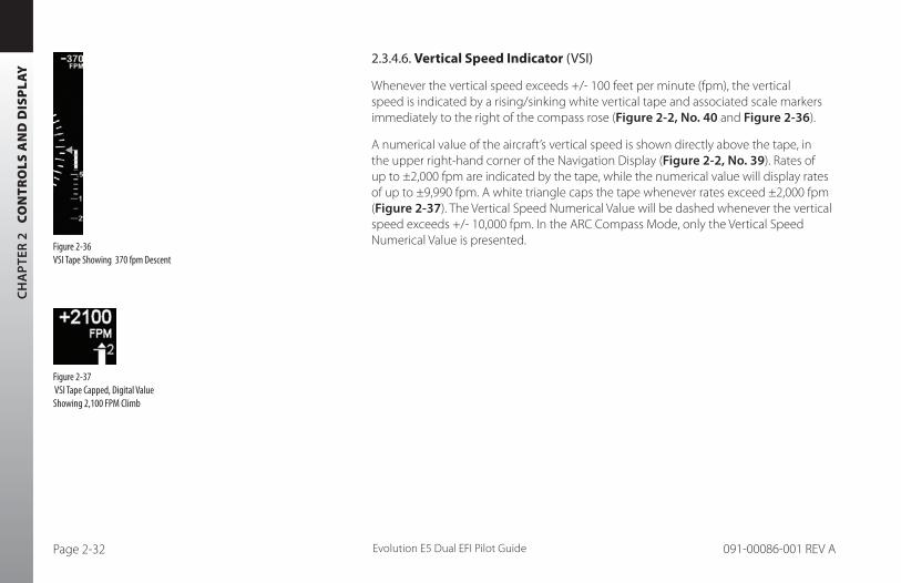
CH
AP
TER
2
CO
NT
RO
LS A
ND
DIS
PLA
Y
Evolution E5 Dual EFI Pilot GuidePage 2-32 091-00086-001 REV A
2.3.4.6. Vertical Speed Indicator (VSI)
Whenever the vertical speed exceeds +/- 100 feet per minute (fpm), the vertical speed is indicated by a rising/sinking white vertical tape and associated scale markers immediately to the right of the compass rose (Figure 2-2, No. 40 and Figure 2-36).
A numerical value of the aircraft’s vertical speed is shown directly above the tape, in the upper right-hand corner of the Navigation Display (Figure 2-2, No. 39). Rates of up to ±2,000 fpm are indicated by the tape, while the numerical value will display rates of up to ±9,990 fpm. A white triangle caps the tape whenever rates exceed ±2,000 fpm (Figure 2-37). The Vertical Speed Numerical Value will be dashed whenever the vertical speed exceeds +/- 10,000 fpm. In the ARC Compass Mode, only the Vertical Speed Numerical Value is presented.
Figure 2-37 VSI Tape Capped, Digital Value Showing 2,100 FPM Climb
Figure 2-36 VSI Tape Showing 370 fpm Descent

CH
AP
TER 3 FLY
ING
TH
E EV
OLU
TIO
N E5
DU
AL EFI
Evolution E5 Dual EFI Pilot Guide Page 3-1091-00086-001 REV A
Chapter 3Flying the Evolution E5 Dual EFI
This chapter provides an overview of flying the Evolution E5 Dual EFI on a cross-country flight, explaining how to access and change the necessary settings of the Evolution E5 Dual EFI.
While you can jump right in to using the Evolution E5 Dual EFI with this chapter, it may be helpful to first read Chapter 2 to become more familiar with the controls, operating logic, and display elements.
The Evolution E5 Dual EFI is a powerful Electronic Flight Instrument System (EFIS), offering the same capabilities and features found in larger glass cockpit systems in airliners, business jets, and newer general aviation aircraft. It is capable of far more than the analog instruments it typically replaces. It will take some time and experience to master all of its advanced capabilities, especially if this is your first exposure to flying an EFIS and a glass cockpit. Nonetheless, in its most basic configuration, the Evolution E5 Dual EFI will look immediately familiar to anyone accustomed to flying mechanical instruments, and its basic operation is very similar and intuitive.
Before flying your new display on an actual flight, first be sure to spend some time with your installer to understand exactly how your aircraft is configured. It’s also recommended to get some dual instruction and practice until you are comfortable with how the display performs and integrates with the other avionics in your airplane.
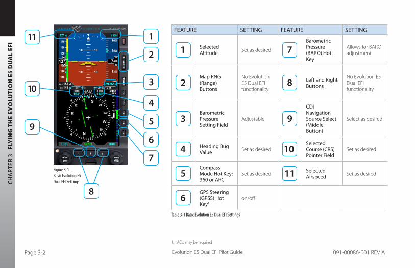
CH
AP
TER
3
FLY
ING
TH
E E
VO
LUT
ION
E5
DU
AL
EFI
Evolution E5 Dual EFI Pilot GuidePage 3-2 091-00086-001 REV A
FEATURE SETTING FEATURE SETTING
Selected Altitude Set as desired
Barometric Pressure (BARO) Hot Key
Allows for BARO adjustment
Map RNG (Range) Buttons
No Evolution E5 Dual EFI functionality
Left and Right Buttons
No Evolution E5 Dual EFI functionality
Barometric Pressure Setting Field
Adjustable
CDI Navigation Source Select (Middle Button)
Select as desired
Heading Bug Value Set as desired
Selected Course (CRS)Pointer Field
Set as desired
Compass Mode Hot Key: 360 or ARC
Set as desired Selected Airspeed Set as desired
GPS Steering (GPSS) Hot Key1
on/off
Table 3-1 Basic Evolution E5 Dual EFI Settings
Figure 3-1 Basic Evolution E5 Dual EFI Settings
1. ACU may be required

CH
AP
TER 3 FLY
ING
TH
E EV
OLU
TIO
N E5
DU
AL EFI
Evolution E5 Dual EFI Pilot Guide Page 3-3091-00086-001 REV A
3.1. Quick Controls OverviewChapter 2 explains the Evolution E5 Dual EFI controls in detail. The following is a quick summary:
Knobs
(See Chapter 2, Section 2.2.1. for details)
The Left or Right Knob each has a Home State, to which it returns after 10 seconds of inactivity. The Left Knob is the CRS Knob, and the Right Knob is the HDG Knob.
• The current function of each knob is shown by its State, displayed immediately above the knob. If the knob state is shown in magenta, turning the knob will change the value of the function shown. If the legend is shown in cyan or green, turning the knob will have no effect.
• From the Home State, pressing the knob once will enable the current function to be set (Knob State color changes from cyan to magenta). Successive presses of the knob will cycle through the functions that knob can control. When the function you want to change is shown in magenta, turning the knob will change its value.
• The Left Knob sets the Course Pointer (CRS, except when Auto Course Select is enabled) and Indicated Airspeed Bug (IAS).
• The Right Knob sets Heading (HDG), Selected Altitude (ALT), and Barometric Pressure Setting (BARO).
• Pressing and holding a knob syncs the selected function.

CH
AP
TER
3
FLY
ING
TH
E E
VO
LUT
ION
E5
DU
AL
EFI
Evolution E5 Dual EFI Pilot GuidePage 3-4 091-00086-001 REV A
Navigation Source Buttons
• Buttons at the bottom of the display couple the available navigation sources to the CDI.
• The Center Button - CDI Navigation Source Select Button (Figure 3-1, Ref. 9) selects the nav source to couple to the CDI and to drive the autopilot (if installed).
Hot Keys
• The three lower keys on the lower right-hand side of the display are Hot Keys, (Figure 3-1, Ref. 5, 6 & 7) the function of which is shown by the legend on the screen immediately adjacent to each key.
• The current status of each Hot Key is shown by the legend in a green label and dark blue letters if active or, in a blue label and green letters if inactive or, in an amber label and dark blue letters if in a coast state.
• Each press of a Hot Key will either toggle its function on or off, or will cycle among available settings (see Chapter 2, Section 2.2.3 for details).

CH
AP
TER 3 FLY
ING
TH
E EV
OLU
TIO
N E5
DU
AL EFI
Evolution E5 Dual EFI Pilot Guide Page 3-5091-00086-001 REV A
3.2. Example Flight ScenarioThis section will walk you through using the Evolution E5 Dual EFI on a flight from Albuquerque International Sunport (KABQ) to Reno/Tahoe International Airport (KRNO), flying Victor airways. This scenario uses one pilot’s technique for setting up the navigation instruments, but there are many other valid possibilities. Use whatever techniques work best for you.
Our aircraft for this example flight scenario is a typical single engine aircraft equipped with a single Garmin GNS-430W WAAS GPS/Nav/Comm and the Bendix/King KFC-150 Autopilot. The Evolution E5 Dual EFI is configured with Auto Course Select enabled (in the main menu), BARO setting in inches Hg, Vspeed text markers displayed, and ARC compass mode.
NOTE The tasks and procedures you will use in your airplane will vary depending on your aircraft and equipment, and on how they are configured and integrated with the display in your specific installation
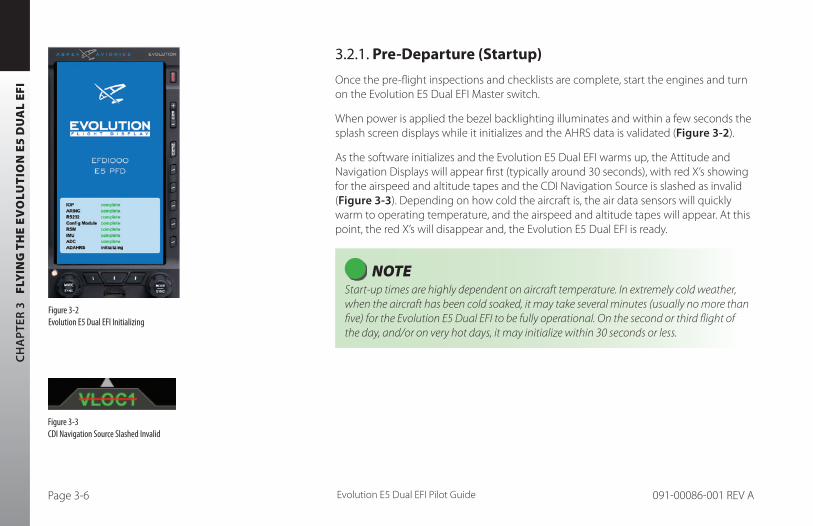
CH
AP
TER
3
FLY
ING
TH
E E
VO
LUT
ION
E5
DU
AL
EFI
Evolution E5 Dual EFI Pilot GuidePage 3-6 091-00086-001 REV A
3.2.1. Pre-Departure (Startup)
Once the pre-flight inspections and checklists are complete, start the engines and turn on the Evolution E5 Dual EFI Master switch.
When power is applied the bezel backlighting illuminates and within a few seconds the splash screen displays while it initializes and the AHRS data is validated (Figure 3-2).
As the software initializes and the Evolution E5 Dual EFI warms up, the Attitude and Navigation Displays will appear first (typically around 30 seconds), with red X’s showing for the airspeed and altitude tapes and the CDI Navigation Source is slashed as invalid (Figure 3-3). Depending on how cold the aircraft is, the air data sensors will quickly warm to operating temperature, and the airspeed and altitude tapes will appear. At this point, the red X’s will disappear and, the Evolution E5 Dual EFI is ready.
NOTE Start-up times are highly dependent on aircraft temperature. In extremely cold weather, when the aircraft has been cold soaked, it may take several minutes (usually no more than five) for the Evolution E5 Dual EFI to be fully operational. On the second or third flight of the day, and/or on very hot days, it may initialize within 30 seconds or less.
Figure 3-2 Evolution E5 Dual EFI Initializing
Figure 3-3 CDI Navigation Source Slashed Invalid

CH
AP
TER 3 FLY
ING
TH
E EV
OLU
TIO
N E5
DU
AL EFI
Evolution E5 Dual EFI Pilot Guide Page 3-7091-00086-001 REV A
Turn the Avionics Master ON. Until the navigation radios are operational, the CDI Navigation Source annunciations on the Evolution E5 Dual EFI is slashed as invalid (Figure 3-4), and the GPS1 caution annunciation on the left (Figure 3-5), display. The CDI Navigation Source Select will default to VLOC1 the first time the Evolution E5 Dual EFI is turned on. Once the nav radio has warmed up, the red line will be removed from the CDI Navigation Source annunciation.
NOTE GPS navigators will not output valid navigation information until programmed with an active flight plan or direct-to waypoint, and thus will be treated as invalid by the Evolution E5 Dual EFI and cannot be selected as a CDI navigation source until they are programmed with an active waypoint.
When the Evolution E5 Dual EFI is interfaced to a compatible GPS navigator, and the navigator’s Instrument Panel Self-Test page is displayed, the indicated lateral deviation can be verified on the display. This confirms that a valid digital signal has been received from the Garmin system.
The interface between the GPS NavCom and the Evolution E5 Dual EFI system should be considered fully operational once the presence of the digital signal is confirmed. If there is no GPS failure annunciation on the Evolution E5 Dual EFI the lateral deviation indication correlates to the indication on the compatible GPS Navigator’s and Self-Test Page, and then the digital signal is confirmed, and the interface is operational.
Figure 3-4 CDI Source Slashed Invalid
Figure 3-5 GPS Caution Annunciations
NOTE The graphics used in this chapter illustrate the descriptions of the features and tasks, but do not necessarily correspond to the values associated with this example flight scenario.

CH
AP
TER
3
FLY
ING
TH
E E
VO
LUT
ION
E5
DU
AL
EFI
Evolution E5 Dual EFI Pilot GuidePage 3-8 091-00086-001 REV A
Once the radios are available, we listen to the ATIS and learn that the local altimeter setting is 30.15 and that Runway 8 is in use for departures.
First set the standby altimeter to 30.15, and then set the Evolution E5 Dual EFI barometric pressure setting.
Set the Barometric Pressure
1. Press the BARO Hot Key. The BARO label above the Right Knob and Barometric Pressure Setting Field appear in magenta - enabled for editing (Figure 3-6).
2. Rotate the Right Knob clockwise to increase or counterclockwise to decrease the value of the Barometric Pressure Setting Field.
3. Once the correct value is selected, press the BARO Hot Key or any knob, button/key to exit the BARO function. After 10 seconds of inaction or if any other button/key is pressed, the BARO function is disabled and the Right Knob returns to normal operation (Figure 3-7).
Figure 3-6 BARO Setting Field Enabled
Figure 3-7 BARO Setting Field Disabled
WARNING Whenever there is a new altimeter setting, set both the Evolution E5 Dual EFI and the standby altimeter.

CH
AP
TER 3 FLY
ING
TH
E EV
OLU
TIO
N E5
DU
AL EFI
Evolution E5 Dual EFI Pilot Guide Page 3-9091-00086-001 REV A
Next, since we’ll be departing from Runway 8, we set our Heading Bug to runway heading, 080°.
Set the Heading Bug
1. Press the Right Knob until HDG displays above the knob and the HDG field is enabled for editing, both rendered in magenta (Figure 3-8). The Heading Bug will also be rendered in magenta, and a dashed magenta line will extend from the ownship symbol to the Heading Bug to make it easier to see the bug position.
2. Rotate the Right Knob to change the value of the Selected Heading field. Rotate clockwise to increase, or counterclockwise to decrease, the value. Once the correct heading is selected and after 10 seconds of inaction, the field is disabled, and the label and field are rendered in cyan (Figure 3-9).
We call Clearance Delivery to pick up our clearance. It is:
Cessna N1234 is cleared to the Reno/Tahoe Airport as filed; Maintain 7,000; Expect 10,000 in five minutes; Departure frequency is 127.4; Squawk 0123.
We copy and read back our clearance, and then set up our avionics for departure. We set our transponder code and comm radio frequencies. Then we enter our flight plan into GPS1, and activate the flight plan. We make sure the CDI button on the GPS Nav/Com is set to GPS.
From past experience, we expect to be vectored past ABQ VOR, and then given a vector to join the departure on the ABQ-to-ZUN leg (a 255º course). While we navigate with GPS, we tune the ABQ VOR into our nav radio.
Figure 3-8 Selected Heading Field Enabled
Figure 3-9 Selected Heading Field Disabled
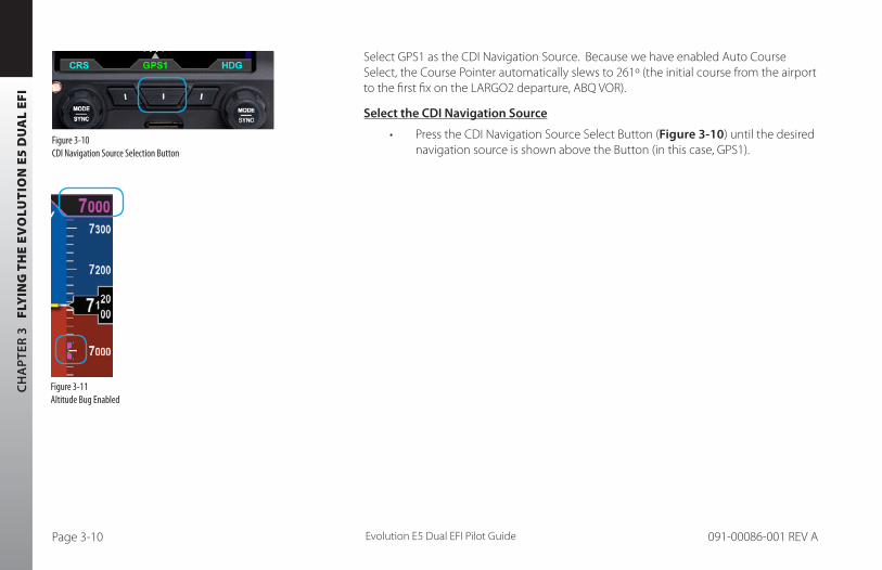
CH
AP
TER
3
FLY
ING
TH
E E
VO
LUT
ION
E5
DU
AL
EFI
Evolution E5 Dual EFI Pilot GuidePage 3-10 091-00086-001 REV A
Select GPS1 as the CDI Navigation Source. Because we have enabled Auto Course Select, the Course Pointer automatically slews to 261º (the initial course from the airport to the first fix on the LARGO2 departure, ABQ VOR).
Select the CDI Navigation Source
• Press the CDI Navigation Source Select Button (Figure 3-10) until the desired navigation source is shown above the Button (in this case, GPS1).
Figure 3-10 CDI Navigation Source Selection Button
Figure 3-11 Altitude Bug Enabled

CH
AP
TER 3 FLY
ING
TH
E EV
OLU
TIO
N E5
DU
AL EFI
Evolution E5 Dual EFI Pilot Guide Page 3-11091-00086-001 REV A
Altitude
Next, we set our assigned initial altitude of 7,000 feet in the Selected Altitude Field. We press the Right Knob twice, changing the legend above the knob to ALT in magenta. Then we turn the Right Knob to set 7,000. This will help us capture and maintain our assigned altitude.
Set the Altitude
1. Press the Right Knob until ALT displays above the Right Knob and the Selected Altitude numerical field and Bug are enabled for editing, all three rendered in magenta (Figures 3-11 and 3-12).
2. Rotate the Right Knob to change the value of the Selected Altitude field. Rotate clockwise to increase, or counterclockwise to decrease, the value.
3. Once the correct value is selected, and after 10 seconds of inaction, the field is disabled and the label, Selected Altitude field, and Bug are rendered in cyan (Figure 3-13).
Figure 3-13 Altitude Disabled
Figure 3-12 Altitude Field Enabled
NOTE Synchronizing the altitude sets the selected altitude to the current altitude (see Chapter 2, Section 2.2.1.3.)

CH
AP
TER
3
FLY
ING
TH
E E
VO
LUT
ION
E5
DU
AL
EFI
Evolution E5 Dual EFI Pilot GuidePage 3-12 091-00086-001 REV A
Our normal climb speed is 120 KIAS, so we set the Airspeed Bug as a reminder. To do so, we press the Left Knob twice, until it shows IAS in magenta above the knob. Then turn the knob until 120 shows in the Selected Airspeed Field.
Set the Airspeed Bug
1. Press the Left Knob until IAS displays above the Left Knob and the Selected Airspeed field and bug are enabled for editing, all three rendered in magenta (Figures 3-14 and 3-15).
2. Rotate the Left Knob to change the value of the Selected Airspeed field. Rotate clockwise to increase, or counterclockwise to decrease, the value.
3. Once the correct value is selected, and after 10 seconds of inaction, the field is disabled, and the label and field are rendered in cyan (Figure 3-16).
Now our avionics are all set, so we taxi out to the runway, do our run-up, and call tower, ready for departure. As we taxi into position and hold on Runway 8, we verify that our Evolution E5 Dual EFI compass shows 080º, lined-up with our pre-set Heading Bug. As tower clears us for takeoff, it tells us to wait until reaching the end of the runway, and then to turn left to heading 250º. Rotate the Right Knob to set the Heading Bug to 250°.
Figure 3-14 Selected Airspeed Field Enabled
Figure 3-16 Selected Airspeed Field Disabled
Figure 3-15 Selected Airspeed Field Enabled
NOTE Synchronizing the airspeed sets the selected airspeed to the current airspeed (see Chapter 2, Section 2.2.1.3.)

CH
AP
TER 3 FLY
ING
TH
E EV
OLU
TIO
N E5
DU
AL EFI
Evolution E5 Dual EFI Pilot Guide Page 3-13091-00086-001 REV A
3.2.2. Departure
As we start the takeoff roll, we note the airspeed on the airspeed comes “alive” at 20 KIAS. All indications are normal, so we continue the takeoff, rotate at 80 KIAS. As we run out of usable runway to land, we bring the gear up, and soon we’re over the end of the 13,800 ft. runway.
We engage HDG mode on the autopilot mode selector, and turn to our assigned 250º heading, which we have already set with the Heading Bug. Through 1,000 feet AGL, we power back and adjust the pitch attitude to maintain our target 120 KIAS climb speed, as shown by the Airspeed Bug on the airspeed tape.
We begin to shallow our climb, and level off at 7,000 feet, engaging ALT hold on the AP mode selector (Figure 3-17).
While on the 250º vector, we pass abeam the ABQ VOR. We also notice that the GPS then sequences to the next flight plan waypoint, the ZUN VOR. The Course Pointer automatically swings left to the new course, 255º.
Albuquerque Departure now tells us to fly heading 220º, and climb and maintain 10,000. Departure also calls out slower traffic at our 10 o’clock, seven miles, west-bound at 8,000, and asks us to expedite our climb through 8,000.
1. Rotate the Right Knob and turn it left to set the Heading Bug to 220º.2. Press the Right Knob twice to activate ALT, and turn it right to set 10,000 in
the Selected Altitude field at the top of the Altitude Tape.
Figure 3-17 Selected Altitude Field

CH
AP
TER
3
FLY
ING
TH
E E
VO
LUT
ION
E5
DU
AL
EFI
Evolution E5 Dual EFI Pilot GuidePage 3-14 091-00086-001 REV A
Auto Course Select has already set our Course Pointer to the 255º course from ABQ to ZUN and a 220º heading sets us up for a nice intercept. We pitch a little higher to climb at 115 KIAS through 8,000 for traffic, then lower the nose to maintain our target airspeed of 120 KIAS by reference to the Airspeed Bug.
At about 9,700 feet, we begin our level-off, and upon reaching 10,000 feet, engage ALT hold on the autopilot’s mode selector.
Departure calls again to hand us off to Albuquerque Center on 133.0. As we’re tuning the radio, we glance at the selected altitude field, our altitude indicates 10,200 and climbing. We quickly stop the climb, correct back down to our assigned altitude of 10,000, and engage the autopilot before calling to check in with Center.
Figure 3-19 CDI “Alive” and Shown Solid
Figure 3-18 CDI Shown Hollow at Full-Scale Deflection
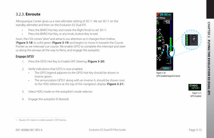
CH
AP
TER 3 FLY
ING
TH
E EV
OLU
TIO
N E5
DU
AL EFI
Evolution E5 Dual EFI Pilot Guide Page 3-15091-00086-001 REV A
3.2.3. Enroute
Albuquerque Center gives us a new altimeter setting of 30.11. We set 30.11 on the standby altimeter and then on the Evolution E5 Dual EFI.
• Press the BARO Hot Key and rotate the Right Knob to set 30.11.• Press the BARO Hot Key, or any knob, button/key to exit.
Soon, the CDI comes “alive” and attracts our attention as it changes from hollow (Figure 3-18) to solid green (Figure 3-19) and begins to move in towards the Course Pointer as we intercept our course. We enable GPSS to complete the intercept and steer us along the airways all the way to Reno, and engage the autopilot.
Engage GPSS1
1. Press the GPSS Hot Key to Enable GPS Steering (Figure 3-20).
2. Verify indications that GPSS is now enabled.• The GPSS legend adjacent to the GPSS Hot Key should be shown in
inverse green.• The annunciation GPSS1 along with an inverse A, should be shown next
to the HDG reference at the top of the navigation display (Figure 3-21).
3. Select HDG mode on the autopilot’s mode selector.
4. Engage the autopilot (if desired).
Figure 3-20 GPSS Enabled legend in Green
Figure 3-21 GPSS Enabled
1. Requires ACU option to enable autopilot / GPS Steering
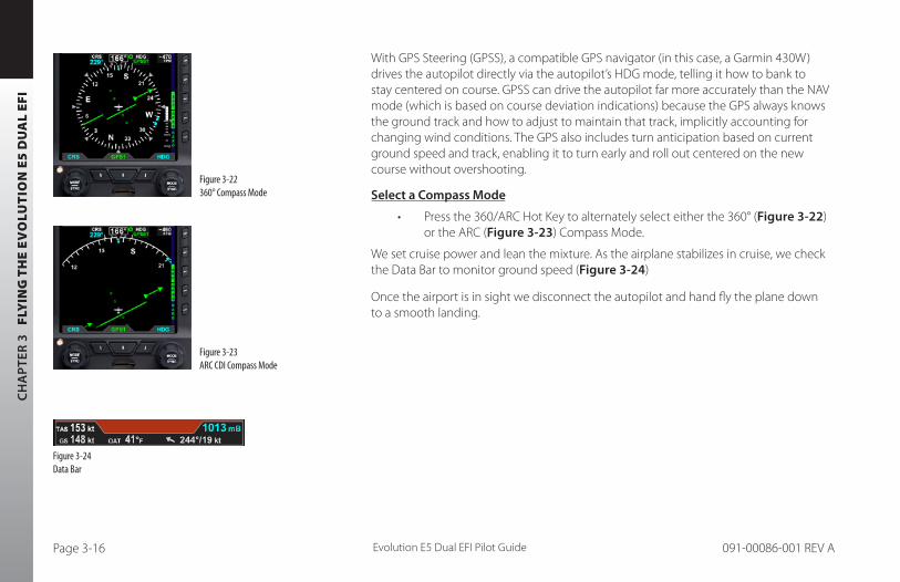
CH
AP
TER
3
FLY
ING
TH
E E
VO
LUT
ION
E5
DU
AL
EFI
Evolution E5 Dual EFI Pilot GuidePage 3-16 091-00086-001 REV A
With GPS Steering (GPSS), a compatible GPS navigator (in this case, a Garmin 430W) drives the autopilot directly via the autopilot’s HDG mode, telling it how to bank to stay centered on course. GPSS can drive the autopilot far more accurately than the NAV mode (which is based on course deviation indications) because the GPS always knows the ground track and how to adjust to maintain that track, implicitly accounting for changing wind conditions. The GPS also includes turn anticipation based on current ground speed and track, enabling it to turn early and roll out centered on the new course without overshooting.
Select a Compass Mode
• Press the 360/ARC Hot Key to alternately select either the 360° (Figure 3-22) or the ARC (Figure 3-23) Compass Mode.
We set cruise power and lean the mixture. As the airplane stabilizes in cruise, we check the Data Bar to monitor ground speed (Figure 3-24)
Once the airport is in sight we disconnect the autopilot and hand fly the plane down to a smooth landing.
Figure 3-22 360° Compass Mode
Figure 3-23 ARC CDI Compass Mode
Figure 3-24 Data Bar

CH
AP
TER 3 FLY
ING
TH
E EV
OLU
TIO
N E5
DU
AL EFI
Evolution E5 Dual EFI Pilot Guide Page 3-17091-00086-001 REV A
3.3 ConclusionThe Evolution E5 Dual EFI is a powerful addition to any cockpit, providing far more capability, information and automation than the mechanical instruments it typically replaces. While it is simple and intuitive enough to start using with only a short orientation, fully understanding and exploiting all of its features require some study and experience.
CAUTION The Garmin 400/500 series navigators continue to output GPS Steering commands to follow the GPS flight plan even when the CDI source is set to VLOC.
The Evolution E5 Dual EFI permits GPSS to be enabled even when VLOC is selected as the CDI navigation source.
Whenever the GPSS is on and the autopilot is in the HDG mode, the autopilot will fly the GPS flight plan.
CH
AP
TER
4
REF
EREN
CE
GU
IDE
Evolution E5 Dual EFI Pilot GuidePage 4-1 091-00086-001 REV A
Chapter 4Reference Guide
The Evolution E5 Dual EFI is a panel-mounted Electronic Flight Instrument System (EFIS) that presents the pilot with displays of attitude, altitude, indicated airspeed, heading, rate of turn, slip/skid, and navigation course deviation information. The system also displays supplemental flight data, such as groundspeed and pilot-selectable indices (bugs), to increase situational awareness and enhance flight safety.
The system components include the Evolution E5 Dual EFI display head, a Remote Sensor Module (RSM), a Configuration Module (CM), and the optional Analog Converter Unit (ACU). Chapter 1, Welcome and Introduction, provides a detailed discussion on the system components.
When interfaced with a compatible autopilot, the Evolution E5 Dual EFI system provides heading and course information to the autopilot, which enables the autopilot to follow the Course and Heading values set by the pilot on the display. When interfaced with a compatible GPS, the Evolution E5 Dual EFI can provide GPS Steering (GPSS) to an autopilot.
NOTE The optional ACU enables the interface of the Evolution E5 Dual EFI system with legacy panel-mounted GPS navigators, VOR radios, and autopilots.

CH
AP
TER 4 R
EFEREN
CE G
UID
E
Evolution E5 Dual EFI Pilot Guide Page 4-2091-00086-001 REV A
4.1. Air Data, Attitude and Heading Reference System (ADAHRS)One of the many benefits of glass cockpit systems like the Aspen Evolution system is that they replace old, less-reliable mechanical instruments and sensors with electronic equivalents. For aircraft elctronic flight instruments, spinning metal gyros are replaced with electronic gyros and accelerometers, and mechanical air data instruments (airspeed indicator, altimeter, and VSI) are replaced by electronic sensors to measure static and ram air pressures. As we’ve all seen with computers and consumer goods, these modern electronic systems tend to be smaller, faster, cheaper, and more reliable than the older technologies they replace, while also enabling many new, advanced features and capabilities.
An electronic system that replaces the functions of the six elctronic flight instruments is often called an ADAHRS (Air Data, Attitude, and Heading Reference System). Sometimes, two separate systems work together to deliver those functions: an AHRS for attitude and heading, and an ADC (Air Data Computer) for airspeed, altitude, and vertical speed. Aspen uses an integrated ADAHRS mounted to the back of the display. While such systems deliver the same basic information to the pilot as the old mechanical instruments, they work in very different ways. It is important that the pilot have at least a basic understanding of how an ADAHRS works to better understand the sorts of failure modes or degraded performance than can occur, how to recognize the symptoms, and what corrective actions the pilot can take.
The Evolution E5 Dual EFI uses Micro Electro-Mechanical Systems (MEMS) technology and solid-state accelerometers and magnetometers on all three axes to provide the attitude reference. Generally, MEMS attitude solutions use multiple sensors and inputs, processed through Kalman filter software, to derive and validate the attitude solution.
The Aspen system uses many different inputs to determine and monitor the aircraft attitude. In this way, the system can validate the derived attitude indication by cross-checking the various inputs to the solution for consistency.

CH
AP
TER
4
REF
EREN
CE
GU
IDE
Evolution E5 Dual EFI Pilot GuidePage 4-3 091-00086-001 REV A
4.1.1. Attitude
The Aspen ADAHRS attitude solution uses inputs from its internal three-axis accelerometers, rate gyros, and magnetometers, supplemented by ram and static air pressure inputs from the aircraft pitot-static system. Failures or incorrect input from any of these sensors (such as might occur if the pitot tube or static system become blocked) will affect the attitude solution. The Evolution E5 Dual EFI is designed to be robust to such failures, either by being tolerant to incorrect inputs, or by detecting and annunciating a degraded attitude solution.
The Aspen ADAHRS includes a Cross-Check Monitor, which predicts the quality of the attitude solution by performing a continuous, real-time statistical analysis of the various parameters computed within the AHRS Kalman filter. When the predicted quality of the attitude calculation drops below a certain threshold, CROSS CHECK ATTITUDE is annunciated on the attitude indicator (Figure 4-1). The annunciation thresholds for the CROSS CHECK ATTITUDE message were determined during company flight tests, and strike a balance between minimizing nuisance annunciations (when the attitude solution is fine) and failing to annunciate (when the attitude solution is significantly reduced). This balance can occasionally result in momentary CROSS CHECK ATTITUDE annunciations, especially during aggressive maneuvering, steep or high-G turns, abrupt pitch changes, etc.
In such situations, these annunciations indicate that the statistical quality of the attitude solution is less than nominal, and that the pilot should cross-check the AHRS against alternate attitude indications. Should the annunciation persist, then degraded AHRS performance is statistically more likely to be experienced. In other words, momentary CROSS CHECK ATTITUDE annunciations indicate that the AHRS solution is working hard enough that the AHRS quality measure has been reduced to something less than that associated with normal, unaccelerated flight. This situation demands increased pilot vigilance and cross-monitoring of other cockpit instrumentation.
Figure 4-1 Cross Check Attitude Annunciation

CH
AP
TER 4 R
EFEREN
CE G
UID
E
Evolution E5 Dual EFI Pilot Guide Page 4-4091-00086-001 REV A
4.1.2. Pitot Obstruction Monitor
Most light aircraft have only a single pitot and static system available for flight instrument use. As such, a common pitot and static input is shared between the Evolution E5 Dual EFI and analog standby instruments. Should one or both of these pitot and static lines become blocked, both the Evolution E5 Dual EFI and any standby airspeed and altitude indicators could display erroneous airspeed and altitude information. Furthermore, because the Evolution E5 Dual EFI uses pitot and static pressures as part of the AHRS attitude calculations, loss or corruption of the pitot or static pressures can also influence the accuracy of the displayed attitude information.
The Evolution E5 Dual EFI has been tested to be robust to these failures, either by being tolerant to incorrect pitot or static inputs, or by detecting and annunciating a degraded attitude solution. When connected to an IFR-certified GPS, the system is further able to detect and annunciate blockages in the pitot system and will use GPS ground speed instead of IAS as part of the AHRS solution. In that case, the system will continue to provide attitude and heading information, and display a ATTITUDE DEGRADED message as a reminder to the pilot to check for ice accumulating on the pitot probe (Figure 4-2).
Once the system detects that the pitot obstruction has been cleared, the ATTITUDE DEGRADED annunciation is removed and the system automatically performs an AHRS in-flight reset.
Should a GPS failure be experienced in flight, the Pitot Obstruction Monitor continues to operate in a fail-safe mode and will continue to detect obstructions in the pitot system that may occur while airborne. However, after landing, the monitor remains active, and, as the airplane slows to taxi speeds, the system will indicate a failure of the AHRS and annunciate CHECK PITOT HEAT. In this circumstance, restoring the GPS will restore normal monitor operation.
Figure 4-2 Attitude Degraded
NOTE Should a loss of GPS occur at the same time the Evolution E5 Dual EFI is in Attitude Degraded mode, the system will red X the attitude and heading information and display a CHECK PITOT HEAT message as a reminder to the pilot to check for ice accumulating on the pitot tube.

CH
AP
TER
4
REF
EREN
CE
GU
IDE
Evolution E5 Dual EFI Pilot GuidePage 4-5 091-00086-001 REV A
In summary, loss or degradation of the Evolution E5 Dual EFI attitude solution is unlikely if the pilot assures the proper operation of the pitot-static system. If the pitot or static system becomes blocked, an ADAHRS internal sensor fails, or a CROSS CHECK ATTITUDE followed by an ATTITUDE DEGRADED indication is frequent or persists, the attitude indication on the Evolution E5 Dual EFI should be considered to be compromised. In this case, the pilot must crosscheck other instruments for attitude reference until the cause of the problem has been identified and resolved and normal system operation has been restored.
4.1.3. Heading
The ADAHRS also includes a slaved compass system that provides accurate magnetic heading indications throughout most operating conditions and phases of flight. Its electronic gyros compensate for turning and acceleration errors, and its remote fluxgate compensates for gyroscopic precession errors, so there is no need for the pilot to adjust heading throughout the flight. Nonetheless, all compass systems are subject to some error, and the pilot should be aware of when and how the heading indication can be affected.
The earth’s magnetic field is measured directly by a 3-axis fluxgate magnetometer built into the Remote Sensor Module (RSM), and magnetic heading is derived from the flux on a plane perpendicular to gravity, providing immunity from pitching and rolling effects. Electronic gyros and accelerometers in the system are then used to stabilize that raw heading data to eliminate the short-term turning and acceleration errors seen in traditional magnetic compasses.
Together, these systems provide accurate heading indications even during aggressive maneuvering. The gyros stabilize magnetic errors while maneuvering and are slaved to the fluxgate, which continuously updates heading to compensate for gyroscopic

CH
AP
TER 4 R
EFEREN
CE G
UID
E
Evolution E5 Dual EFI Pilot Guide Page 4-6091-00086-001 REV A
precession. The end result is a compass system that requires no pilot action to show accurate magnetic heading throughout the flight.
Just like other compass systems, the accuracy of the flux gate is affected by its location on the airframe. Ferrous metal structures, electrical fields produced by motors, pumps, wiring, magnets in cabin speakers and other airframe-related sources of interference either constant or momentary (i.e. operating an electric trim motor, windshield heat, pumps, etc) can all affect the accuracy of the compass. The installer can compensate for much of this interference when calibrating the RSM, but some effects cannot be eliminated. Proper location of the RSM during installation is critical to the AHRS performance and accuracy.
Furthermore, all magnetic compass systems are susceptible to local disturbances in the earth’s magnetic field (some of which are shown on aviation charts or by NOTAM) and will exhibit degraded performance when operating in extreme northern and southern latitudes close to the earth’s magnetic poles.
4.1.4. Free Gyro Mode
When the Evolution E5 Dual EFI system detects that the horizontal component of the earth’s magnetic field is no longer strong enough to provide reliable heading data, it will detect the condition and annunciate that the heading system is no longer slaved to magnetic north. If the condition persists, attitude and heading indications are removed.
While the condition can occur at greater distances, it is most likely to be observed within 750 nautical miles from the magnetic poles. In the Northern Hemisphere, this equates to operations in the Arctic Islands found north of continental North America.

CH
AP
TER
4
REF
EREN
CE
GU
IDE
Evolution E5 Dual EFI Pilot GuidePage 4-7 091-00086-001 REV A
Two minutes after detection, a FREE GYRO MODE annunciation will be presented across the Navigation display, indicating the heading system no longer can be aligned with magnetic north. Some precession of the heading is possible, especially during abrupt maneuvers. If the condition persists for four more minutes (six minutes total) the attitude and heading indicators will be removed and replaced with red X indications. When the conditions causing Free Gyro Mode are no longer present, attitude and heading indications will be restored after an automatic AHRS reset.
4.1.5. Degraded Mode
For Degraded ADAHRS Performance, reference the following:
• Sections 6.1. Pitot/Static System Blockage • Sections 6.8. In-Flight AHRS Reset • Geographic Limitations in the Aircraft Flight Manual Supplement
that was installed in the aircraft with your Evolution E5 Dual EFI.

CH
AP
TER 4 R
EFEREN
CE G
UID
E
Evolution E5 Dual EFI Pilot Guide Page 4-8091-00086-001 REV A
4.2. Attitude Display
4.2.1. Attitude Indicator
The Attitude Indicator consists of an aircraft reference symbol on a blue (sky) and brown (ground) background. The white horizon line separates the sky from the ground and extends to the edge of the display. The Roll Scale curves over the top of the Attitude Indicator while the Pitch Scale extends vertically in the middle. The slip/skid rectangle is directly underneath the roll pointer (Figure 4-3).
Sky Pitch Scale
Aircraft Reference Symbol Roll Scale
Horizon Line Roll Pointer
Ground Slip/Skid Indicator
The Attitude Indicator cannot be disabled by the pilot. The Aircraft Reference Symbol is fixed relative to the Attitude Indicator and overlays all other Attitude Indicator symbols. Pitch and roll panel tilt adjustments are is provided to installers to compensate for variations in installations and tilted panels. NOTE
A red X and the annunciation ATTITUDE FAIL displays on the Attitude Indicator as long as pitch or roll attitude data is invalid (Figure 4-4).
Figure 4-4 Pitch and/or Roll Data Invalid
Figure 4-3 Attitude Indicator

CH
AP
TER
4
REF
EREN
CE
GU
IDE
Evolution E5 Dual EFI Pilot GuidePage 4-9 091-00086-001 REV A
4.2.1.1. Roll Scale
The Roll Scale is displayed at the top of the Attitude Indicator and comprises a moving scale set against a fixed, white, triangle roll pointer (Figure 4-3, Ref 6 & 7). Tick marks are displayed at 0º, 10º, 20º, 30º, 45º, and 60º of roll. The 45º marks are triangles.
4.2.1.2. Pitch Scale
The pitch scale consists of minor pitch marks in 2.5º increments up to ±20º and major pitch marks in 10º increments up to ±90º (Figure 4-3, Ref 5). Red chevrons come into view for nose-up pitch angles of 15º or more (Figure 4-5), and nose-down pitch angles of 10º or less (Figure 4-6). The pitch chevrons aid the pilot in unusual attitude recovery.
The range of movement of the background sky and ground boundaries are limited so that some sky or ground is always visible.
4.2.1.3. Slip/Skid Indicator
The Slip/Skid Indicator is the small white rectangle under the roll pointer (Figure 4-3, Ref 8). The Slip/Skid Indicator moves left and right relative to the roll pointer in proportion to lateral acceleration. The width of the rectangle is equivalent to the width of the ball in a mechanical inclinometer.
Figure 4-5 Pitch Markings Large Pitch Down
Figure 4-6 Pitch MarkingsLarge Pitch Up
NOTE While operating in Degraded Mode both the Slip/Skid indicator and Turn Rate indicator on the Evolution E5 Dual EFI will be removed. Refer to your legacy instruments for these indications.
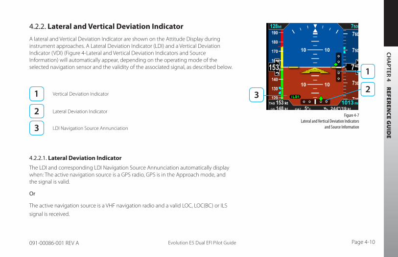
CH
AP
TER 4 R
EFEREN
CE G
UID
E
Evolution E5 Dual EFI Pilot Guide Page 4-10091-00086-001 REV A
4.2.2. Lateral and Vertical Deviation Indicator
A lateral and Vertical Deviation Indicator are shown on the Attitude Display during instrument approaches. A Lateral Deviation Indicator (LDI) and a Vertical Deviation Indicator (VDI) (Figure 4-Lateral and Vertical Deviation Indicators and Source Information) will automatically appear, depending on the operating mode of the selected navigation sensor and the validity of the associated signal, as described below.
Vertical Deviation Indicator
Lateral Deviation Indicator
LDI Navigation Source Annunciation
4.2.2.1. Lateral Deviation Indicator
The LDI and corresponding LDI Navigation Source Annunciation automatically display when: The active navigation source is a GPS radio, GPS is in the Approach mode, and the signal is valid.
Or
The active navigation source is a VHF navigation radio and a valid LOC, LOC(BC) or ILS
signal is received.
Figure 4-7 Lateral and Vertical Deviation Indicators
and Source Information
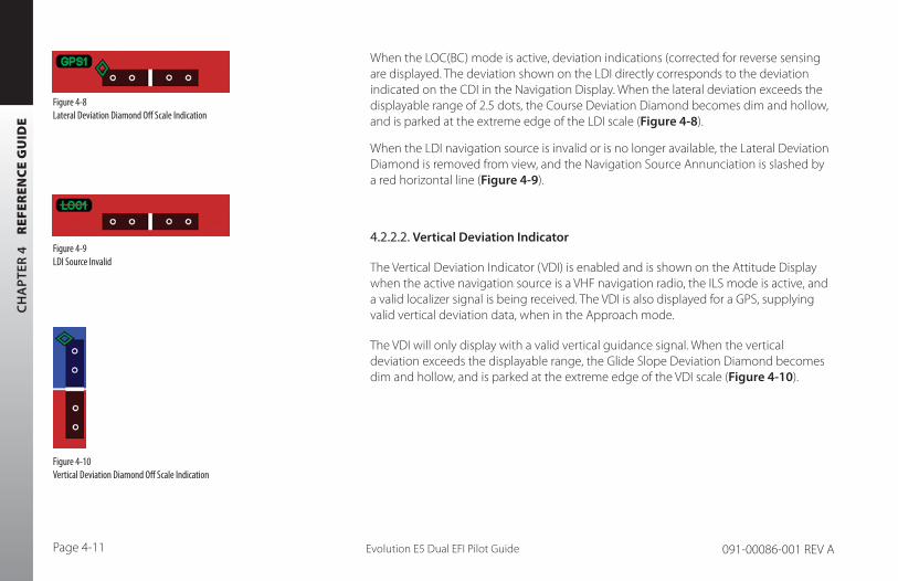
CH
AP
TER
4
REF
EREN
CE
GU
IDE
Evolution E5 Dual EFI Pilot GuidePage 4-11 091-00086-001 REV A
When the LOC(BC) mode is active, deviation indications (corrected for reverse sensing are displayed. The deviation shown on the LDI directly corresponds to the deviation indicated on the CDI in the Navigation Display. When the lateral deviation exceeds the displayable range of 2.5 dots, the Course Deviation Diamond becomes dim and hollow, and is parked at the extreme edge of the LDI scale (Figure 4-8).
When the LDI navigation source is invalid or is no longer available, the Lateral Deviation Diamond is removed from view, and the Navigation Source Annunciation is slashed by a red horizontal line (Figure 4-9).
4.2.2.2. Vertical Deviation Indicator
The Vertical Deviation Indicator (VDI) is enabled and is shown on the Attitude Display when the active navigation source is a VHF navigation radio, the ILS mode is active, and a valid localizer signal is being received. The VDI is also displayed for a GPS, supplying valid vertical deviation data, when in the Approach mode.
The VDI will only display with a valid vertical guidance signal. When the vertical deviation exceeds the displayable range, the Glide Slope Deviation Diamond becomes dim and hollow, and is parked at the extreme edge of the VDI scale (Figure 4-10).
Figure 4-10 Vertical Deviation Diamond Off Scale Indication
Figure 4-9 LDI Source Invalid
Figure 4-8Lateral Deviation Diamond Off Scale Indication
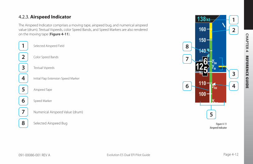
CH
AP
TER 4 R
EFEREN
CE G
UID
E
Evolution E5 Dual EFI Pilot Guide Page 4-12091-00086-001 REV A
Figure 4-11 Airspeed Indicator
4.2.3. Airspeed Indicator
The Airspeed Indicator comprises a moving tape, airspeed bug, and numerical airspeed value (drum). Textual Vspeeds, color Speed Bands, and Speed Markers are also rendered on the moving tape (Figure 4-11).
Selected Airspeed Field
Color Speed Bands
Textual Vspeeds
Initial Flap Extension Speed Marker
Airspeed Tape
Speed Marker
Numerical Airspeed Value (drum)
Selected Airspeed Bug
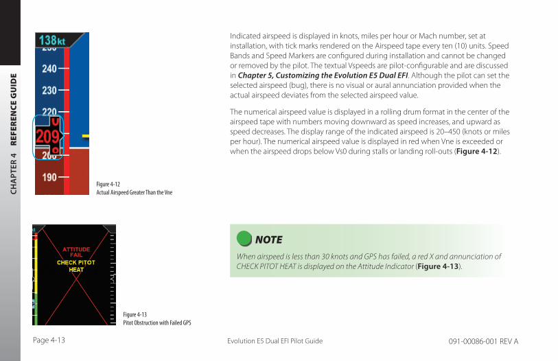
CH
AP
TER
4
REF
EREN
CE
GU
IDE
Evolution E5 Dual EFI Pilot GuidePage 4-13 091-00086-001 REV A
Indicated airspeed is displayed in knots, miles per hour or Mach number, set at installation, with tick marks rendered on the Airspeed tape every ten (10) units. Speed Bands and Speed Markers are configured during installation and cannot be changed or removed by the pilot. The textual Vspeeds are pilot-configurable and are discussed in Chapter 5, Customizing the Evolution E5 Dual EFI. Although the pilot can set the selected airspeed (bug), there is no visual or aural annunciation provided when the actual airspeed deviates from the selected airspeed value.
The numerical airspeed value is displayed in a rolling drum format in the center of the airspeed tape with numbers moving downward as speed increases, and upward as speed decreases. The display range of the indicated airspeed is 20–450 (knots or miles per hour). The numerical airspeed value is displayed in red when Vne is exceeded or when the airspeed drops below Vs0 during stalls or landing roll-outs (Figure 4-12).
NOTE When airspeed is less than 30 knots and GPS has failed, a red X and annunciation of CHECK PITOT HEAT is displayed on the Attitude Indicator (Figure 4-13).
Figure 4-12 Actual Airspeed Greater Than the Vne
Figure 4-13 Pitot Obstruction with Failed GPS

CH
AP
TER 4 R
EFEREN
CE G
UID
E
Evolution E5 Dual EFI Pilot Guide Page 4-14091-00086-001 REV A
4.2.3.1. Selected Airspeed
The Selected Airspeed Field value and associated Airspeed Bug are shown on the Airspeed Tape. The Selected Airspeed Field value is shown at the top of the Airspeed Tape. The Airspeed Bug is displayed next to the Airspeed Tape when the Selected Airspeed value is within the visible range of the tape. The Selected Airspeed Field’s default value is 20 knots Indicated Airspeed (IAS), or the value previously set. SYNCing the IAS field sets the Selected Airspeed Field value to the current indicated airspeed (Section 2.2.1.3). Setting the Selected Airspeed Field to a value less than 20 disables the Airspeed Bug and dashes the Selected Airspeed Field value.
Set Airspeed Bug
1. Press the Left Knob until IAS is shown above the Left Knob.
The Airspeed Field and Airspeed Bug appear in magenta - enabled for editing (Figure 4-14).
2. Rotate the Left Knob clockwise to increase, or counterclockwise to decrease the airspeed value in the Selected Airspeed Field.
After 10 seconds of inactivity, label, field and bug appear in cyan (Figure 4-15).
Figure 4-14 Airspeed Bug Selected to Edit
Figure 4-15 New Airspeed Selected
NOTE A typical installation sets the Tapes (TPS) display to UNLOCKED, allowing the pilot to display or hide the Airspeed and Altitude Tapes as desired.

CH
AP
TER
4
REF
EREN
CE
GU
IDE
Evolution E5 Dual EFI Pilot GuidePage 4-15 091-00086-001 REV A
4.2.3.2. Airspeed Display
The airspeed tape can be turned off at the pilot’s discretion to facilitate screen declutter. This setting will be retained when the system is turned off then powered on again.
Hide/Display Airspeed Tape
1. Press MENU Button.2. Rotate Right Knob until first Menu Key displays TPS (Figure 4-16).3. Press TPS Menu Key.
TPS label and EDIT VALUE label (above Right Knob) appear in magenta.
4. Rotate Right Knob to the desired value: ENABLE or DISABLE (Figure 4-17).5. Press MENU Button to exit.
Figure 4-16 Editing Airspeed Tape Display
Figure 4-17 Tapes (TPS) Disabled
NOTE The tapes can also be turned off for screen declutter. Setting will be retained when Evolution E5 Dual EFI is turned off.
NOTE When the Airspeed Tape is disabled, the numerical display of the selected airspeed remains. An installer can disable and remove the Selected Airspeed Field from the display.

CH
AP
TER 4 R
EFEREN
CE G
UID
E
Evolution E5 Dual EFI Pilot Guide Page 4-16091-00086-001 REV A
Figure 4-18 Altimeter
4.2.4. Altimeter
The altimeter comprises an Altitude Bug, Numerical Altitude Value (drum), Altitude Tape, and Selected Altitude Field value. (Figure 4-18).
Selected Altitude Field
Numerical Altitude Value
Altitude Tape
The Altitude Tape range is from -1,600 to 51,000 feet. Major tick marks are provided every 100 feet and minor tick marks every 20 feet. A barometric pressure adjustment (BARO) is provided to the pilot to accurately display the aircraft’s altitude above mean sea level.
The Numerical Altitude Value is shown in a rolling drum format in the center of the Altimeter Tape, with numbers moving downward as the altitude increases and upward as altitude decreases. The Numerical Altitude Value shows the altitude to the nearest 20 feet.
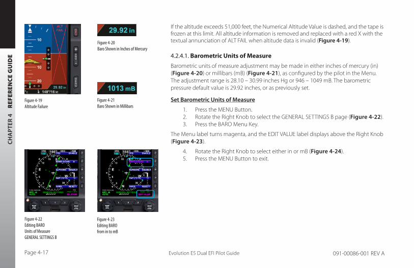
CH
AP
TER
4
REF
EREN
CE
GU
IDE
Evolution E5 Dual EFI Pilot GuidePage 4-17 091-00086-001 REV A
If the altitude exceeds 51,000 feet, the Numerical Altitude Value is dashed, and the tape is frozen at this limit. All altitude information is removed and replaced with a red X with the textual annunciation of ALT FAIL when altitude data is invalid (Figure 4-19).
4.2.4.1. Barometric Units of Measure
Barometric units of measure adjustment may be made in either inches of mercury (in) (Figure 4-20) or millibars (mB) (Figure 4-21), as configured by the pilot in the Menu. The adjustment range is 28.10 – 30.99 inches Hg or 946 – 1049 mB. The barometric pressure default value is 29.92 inches, or as previously set.
Set Barometric Units of Measure
1. Press the MENU Button.2. Rotate the Right Knob to select the GENERAL SETTINGS B page (Figure 4-22).3. Press the BARO Menu Key.
The Menu label turns magenta, and the EDIT VALUE label displays above the Right Knob (Figure 4-23).
4. Rotate the Right Knob to select either in or mB (Figure 4-24).5. Press the MENU Button to exit.
Figure 4-20 Baro Shown in Inches of Mercury
Figure 4-21 Baro Shown in Millibars
Figure 4-19 Altitude Failure
Figure 4-22 Editing BARO Units of Measure GENERAL SETTINGS B
Figure 4-23 Editing BARO from in to mB
CH
AP
TER 4 R
EFEREN
CE G
UID
E
Evolution E5 Dual EFI Pilot Guide Page 4-18091-00086-001 REV A
Set the Barometric Pressure
1. Press the BARO Hot Key.
The BARO label above the Right Knob and Barometric Pressure Setting Field appear in magenta (Figure 4-25).
2. Rotate the Right Knob to change the value of the Barometric Pressure Setting Field.
3. Press the BARO Hot Key or any knob, button/key to exit.
If no action is taken, after 10 seconds of inactivity, the label, and field are rendered in cyan.
WARNING Always check and set the Evolution E5 Dual EFI BARO whenever the mechanical altimeter is adjusted
Figure 4-25 BARO Field Enabled
Figure 4-24 BARO Set to mB (millibars)

CH
AP
TER
4
REF
EREN
CE
GU
IDE
Evolution E5 Dual EFI Pilot GuidePage 4-19 091-00086-001 REV A
NOTE Rotating the knob quickly will change the altitude value in larger increments.
NOTE Since the altitude tape display is limited to approximately 400 feet, the altitude bug symbol is shown on the altitude tape when the Selected Altitude Field value is within the visible range of the current altitude.
Figure 4-26 Altitude Bug
4.2.4.2. Selected Altitude Field
The Selected Altitude Field value is displayed at the top of the Altitude Tape. The Selected Altitude Field range is 100 to 51,000 feet, in 100 foot increments. The default value for the Selected Altitude value is 100 feet, or the previously set value. Additionally, the Altitude Bug is displayed adjacent to the Altitude Tape and at the Selected Altitude Field value when within the visible range of the current altitude.
Set Altitude Bug
1. Press the Right Knob until ALT displays above the Right Knob.
The Selected Altitude Field and bug are enabled for editing, all rendered in magenta (Figure 4-26).
2. Rotate the Right Knob (clockwise to increase, or counterclockwise to decrease) to change the value of the Selected Altitude Field.
Once the correct value is selected, and after 10 seconds of inaction, the field is disabled, and the label, field, and bug are rendered in cyan.

CH
AP
TER 4 R
EFEREN
CE G
UID
E
Evolution E5 Dual EFI Pilot Guide Page 4-20091-00086-001 REV A
NOTE When the Altitude tape is disabled, the numerical display of the selected altitude remain on. However, an installer can disable and remove the Selected Altitude Fields, and Markers from the display.
NOTE A Evolution E5 Dual EFI installation sets the tapes display to UNLOCKED, allowing the pilot to display or hide the Airspeed and Altitude tapes as desired.
Figure 4-27 Editing Airspeed and Altitude Tape Display
Figure 4-28 Airspeed and Altitude Tape Disabled
4.2.4.3. Altitude Display
The altitude tape can be turned off, at the pilot’s discretion, to facilitate screen declutter. Both Airspeed and Altitude tapes are affected by this action.
Hide/Display Airspeed and Altitude Tape
1. Press the MENU Button.2. Rotate the Right Knob counterclockwise until GENERAL SETTINGS page
displays (Figure 4-27).3. Press the TPS Menu Key.
The Menu label turns magenta, and the EDIT VALUE label displays above the Right Knob.
4. Rotate the Right Knob to the desired value, ENABLE (On) or DISABLE (Off ) (Figure 4-28).
5. Press the MENU Button to exit.

CH
AP
TER
4
REF
EREN
CE
GU
IDE
Evolution E5 Dual EFI Pilot GuidePage 4-21 091-00086-001 REV A
4.3. Data BarThe Data Bar presents True Airspeed (TAS), GPS, Ground Speed (GS), Outside Air Temperature (OAT) , Wind Direction, Wind Speed and Barometric Pressure Settings, as shown in (Figure 4-29) when enabled. The Data Bar is always present on the display. Invalid or out-of-range Data Bar values are dashed.
True Airspeed (TAS) Wind Direction Arrow
Barometric Pressure Setting Field
Outside Air Temperature (OAT)
Wind Speed Ground Speed (GS)
Wind Direction
4.3.1. True Airspeed (when enabled)
The True Airspeed (TAS) is displayed in the upper left of the Data Bar. The TAS has a range of 20–999 knots or mph, using the same unit of measurement as the aircraft’s Airspeed Indicator. The TAS is a correction of the IAS for nonstandard pressure and temperature.
Figure 4-29 Data Bar

CH
AP
TER 4 R
EFEREN
CE G
UID
E
Evolution E5 Dual EFI Pilot Guide Page 4-22091-00086-001 REV A
4.3.2. Ground Speed
The Ground Speed (GS) comes from a configured GPS navigator and is digitally displayed in the lower left corner of the Data Bar with a value range of 5–999 knots or mph, using the same unit of measurement as the Airspeed Indicator.
4.3.3. Outside Air Temperature (when enabled)
The Outside Air Temperature (OAT) is displayed in the center of the Data Bar (Figure 4-29). The temperature is obtained from the temperature sensor located in the RSM. Temperature sensor ranges from -55°C to +80°C (-67°F to +176°F).
Set OAT Units of Measure
1. Press the MENU Button.2. Rotate the Right Knob counterclockwise until GENERAL SETTINGS
page displays.3. Press the OAT Menu Key.
The Menu label turns magenta and the EDIT VALUE label displays above the Right Knob (Figure 4-30a).
4. Rotate the Right Knob to select °C or °F (Figure 4-30b).5. Press the MENU Button to exit.
Figure 4-30a Editing OAT Units of Measure from ºC to ºF
Figure 4-30b OAT Set to ºC

CH
AP
TER
4
REF
EREN
CE
GU
IDE
Evolution E5 Dual EFI Pilot GuidePage 4-23 091-00086-001 REV A
4.3.4. Wind Speed, Direction, and Arrow (when enabled)
The Wind Speed, Direction, and Direction Arrow are displayed in the lower right portion of the Data Bar. The Wind Speed has a range of 10-999 knots or mph, using the same units of measure as the Airspeed Indicator.
The Wind Direction and Arrow have a range of 001°-360°, using the same direction reference used by the Direction Indicator. The arrow points in the direction of the wind and is displayed relative to the current direction of flight. For example, if the current direction of flight is 360°, the arrow will point straight down on the display (a headwind blowing toward your aircraft).
When the computed wind speed is below 10 knots or mph (depending on aircraft configuration) the wind speed and direction values are blank, and the wind arrow is removed. If the wind data is out of range or invalid, the values are dashed, and the wind arrow is removed.
4.3.5. Barometric Pressure Setting Display
The Barometric Pressure Setting Field is displayed on the upper right corner of the Data Bar and is pilot-adjustable, as discussed in Section 4.2.3.1. When the Altitude Tape is disabled, the Barometric Pressure Setting field remains visible. However, an installer can disable the field and remove it from the display. Section 4.2.3.1 provides complete information and step-by-step instructions for setting the barometric pressure.
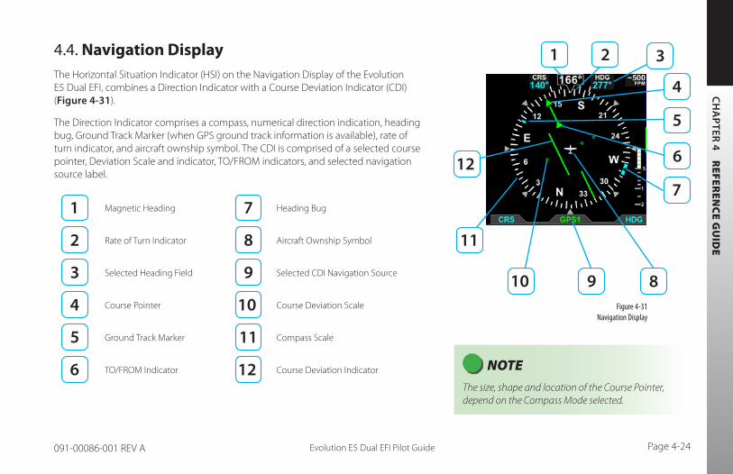
CH
AP
TER 4 R
EFEREN
CE G
UID
E
Evolution E5 Dual EFI Pilot Guide Page 4-24091-00086-001 REV A
4.4. Navigation DisplayThe Horizontal Situation Indicator (HSI) on the Navigation Display of the Evolution E5 Dual EFI, combines a Direction Indicator with a Course Deviation Indicator (CDI) (Figure 4-31).
The Direction Indicator comprises a compass, numerical direction indication, heading bug, Ground Track Marker (when GPS ground track information is available), rate of turn indicator, and aircraft ownship symbol. The CDI is comprised of a selected course pointer, Deviation Scale and indicator, TO/FROM indicators, and selected navigation source label.
Magnetic Heading Heading Bug
Rate of Turn Indicator Aircraft Ownship Symbol
Selected Heading Field Selected CDI Navigation Source
Course Pointer Course Deviation Scale
Ground Track Marker Compass Scale
TO/FROM Indicator Course Deviation Indicator
Figure 4-31 Navigation Display
NOTE The size, shape and location of the Course Pointer, depend on the Compass Mode selected.
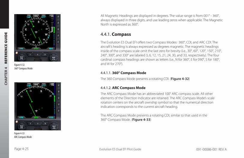
CH
AP
TER
4
REF
EREN
CE
GU
IDE
Evolution E5 Dual EFI Pilot GuidePage 4-25 091-00086-001 REV A
All Magnetic Headings are displayed in degrees. The value range is from 001° - 360°, always displayed in three digits, and use leading zeros when applicable. The Magnetic North is expressed as 360°.
4.4.1. Compass
The Evolution E5 Dual EFI offers two Compass Modes: 360°, CDI, and ARC CDI. The aircraft’s heading is always expressed as degrees magnetic. The magnetic headings inside of the compass scale omit the last zero for brevity (i.e., 30°, 60°, 120°, 150°, 210°, 240°, 300°, and 330° are labeled 3, 6, 12, 15, 21, 24, 30, and 33, respectively). The four cardinal compass headings are shown as letters (i.e., N for 360°, E for 090°, S for 180°, and W for 270°).
4.4.1.1. 360° Compass Mode
The 360 Compass Mode presents a rotating CDI. (Figure 4-32)
4.4.1.2. ARC Compass Mode
The ARC Compass Mode has an abbreviated 100° ARC compass scale. All other elements of the Direction Indicator are retained. The ARC Compass Mode’s scale rotation centers on the aircraft ownship symbol so that the numerical direction indication corresponds to the current aircraft heading. The ARC Compass Mode presents a rotating CDI, similar to that used in the 360° Compass Mode. (Figure 4-33)
Figure 4-32 360° Compass Mode
Figure 4-33 ARC Compass Mode

CH
AP
TER 4 R
EFEREN
CE G
UID
E
Evolution E5 Dual EFI Pilot Guide Page 4-26091-00086-001 REV A
Select Compass Type
1. Press the 360/ARC Hot Key (Figure 4-34) to alternately select either the 360° or ARC Compass Mode.
The Navigation Display changes and the Hot Key label reflects the currently selected Compass Mode (Figures 4-35 and 4-36).
Figure 4-35 ARC Compass Mode
Figure 4-36 360˚ Compass Mode
Figure 4-34 360/ARC Hot Key
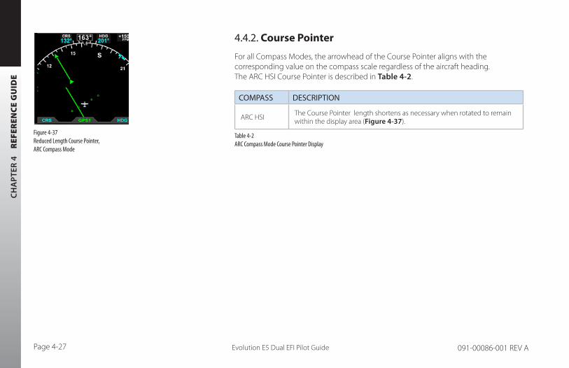
CH
AP
TER
4
REF
EREN
CE
GU
IDE
Evolution E5 Dual EFI Pilot GuidePage 4-27 091-00086-001 REV A
4.4.2. Course Pointer
For all Compass Modes, the arrowhead of the Course Pointer aligns with the corresponding value on the compass scale regardless of the aircraft heading. The ARC HSI Course Pointer is described in Table 4-2.
COMPASS DESCRIPTION
ARC HSI The Course Pointer length shortens as necessary when rotated to remain within the display area (Figure 4-37).
Table 4-2 ARC Compass Mode Course Pointer Display
Figure 4-37 Reduced Length Course Pointer, ARC Compass Mode

CH
AP
TER 4 R
EFEREN
CE G
UID
E
Evolution E5 Dual EFI Pilot Guide Page 4-28091-00086-001 REV A
4.4.3. TO/FROM Indicator
Each of the Compass Modes has a TO/FROM indicator. The TO/FROM indicator shows whether the aircraft is heading toward a waypoint or radio navaid, or from a waypoint or radio navaid. For each Compass Mode, the TO/FROM indication is slightly different, as described in Table 4-3.
COMPASS DESCRIPTION
360º and ARC
(Reduced Without
Length Course
Pointer)
The TO indicator is an arrowhead on the top of the Course Pointer, oriented in the same direction as the course arrowhead (Figure 4-38a). The FROM indicator is an arrowhead on the bottom half of the Course Pointer, oriented in the direction opposite to the course arrowhead (Figure 4-38b).
ARC
(With Reduced
Length Course
Pointer)
The TO indicator is shown as two arrowheads, one on each half of the Course Pointer, oriented in the same direction as the course arrowhead (Figure 4-39a). The FROM indicator is shown as two arrowheads, one on each half of the Course Pointer, oriented opposite to the direction of the course arrowhead (Figure 4-39b).
Table 4-3 TO/FROM Indicator Description
Figure 4-38a 360° and ARC TO Indication
(without Reduced Length Course Pointer)
Figure 4-38b 360° and ARC FROM Indication
(without Reduced Length Course Pointer)Figure 4-39a ARC TO Indication(with Reduced Length Course Pointer)
Figure 4-39b ARC FROM Indication(with Reduced Length Course Pointer)

CH
AP
TER
4
REF
EREN
CE
GU
IDE
Evolution E5 Dual EFI Pilot GuidePage 4-29 091-00086-001 REV A
4.4.4. Course Deviation Indicator and Scale
Selected course deviation is depicted by a Course Deviation Indicator and Scale. Deviation is indicated by positioning the Course Deviation Indicator on the Scale corresponding to the lateral deviation value.
The 360 and ARC Compass Modes show the CDI as a green line centered on the display and parallel with the Course Pointer. The scale is a set of four hollow, green dots that are perpendicular to the Course Pointer (Figure 4-40).
Course Deviation Indicator Course Deviation Scale
The ARC CDI Compass Mode’s CDI and Scale are located at the bottom of the lower display. The indicator is a green diamond, and the Scale is a set of four hollow, white dots with a white index mark at the center (Figure 4-41).
When the lateral deviation exceeds the maximum displayable range of 2.5 dots, the Deviation Indicator bar as applicable, becomes hollow and darker (Figure 4-41).
Localizer Back Course (BC) Operation
When flying a Back Course final approach (the aircraft heading is opposite to the localizer front course), set the CRS value to the front course localizer or ILS approach value. The tail of the CDI will match the back-course runway’s magnetic orientation.
When the LOC(BC) mode is active, a “BC” annunciation is shown on the Attitude Display left of the Lateral Deviation Indicator (LDI) (Figure 4-41). The left/right deviation indications are corrected for reverse sensing and will behave intuitively, the same as with a front course localizer.
Figure 4-40 Deviation Indicator, 360° and ARC Compass Modes
Figure 4-41 Deviation Exceeded, 360° and ARC Compass Modes

CH
AP
TER 4 R
EFEREN
CE G
UID
E
Evolution E5 Dual EFI Pilot Guide Page 4-30091-00086-001 REV A
4.4.5. CDI Navigation Source
When the Evolution E5 Dual EFI powers up, the default Selected CDI Navigation Source is the last source selected. The pilot can select from any of the installed navigation sources using the Middle Button. The Evolution E5 Dual EFI supports navigation information display from VHF Omni-directional Radio Range (VOR) navaids, and Global Positioning Systems (GPS). There can only be one GPS Nav/Com and one VHF Nav/Com systems integrated with the Evolution E5 Dual EFI.
When integrated GPS/VLOC equipment are installed, the GPSS signal source is provided by the associated GPS whenever the CDI navigation source is selected to either the GPS side or the VLOC side of the integrated GPS/VLOC receiver.
Figure 4-42 Back Course (BC) Annunciation

CH
AP
TER
4
REF
EREN
CE
GU
IDE
Evolution E5 Dual EFI Pilot GuidePage 4-31 091-00086-001 REV A
Select the CDI Navigation Source
• Press the CDI Navigation Source Select button until the desired navigation source is displayed above the button (e.g., GPS1, VLOC1) (Figure 4-43).
CDI Navigation Source Select Button
Selected CDI Source Label
Figure 4-43 CDI Source selection and Information
NOTE For integrated systems, the CDI navigation source label indicates the current operating mode (GPS or VLOC) of the GPS/VHF NAV system.
When an integrated system is selected but not reporting its operating mode, VLOC1 is shown as the Selected CDI Navigation Source.
Refer to the GPS or VHF NAV AFMS for information on the operation of the connected navigation equipment.
NOTE There are many radio configurations available. Your authorized Aspen Avionics Dealer can explain the configuration used on your aircraft.

CH
AP
TER 4 R
EFEREN
CE G
UID
E
Evolution E5 Dual EFI Pilot Guide Page 4-32091-00086-001 REV A
4.4.6. Auto Course
The pilot can either use the Auto Course (AUTOCRS) or manually set a CRS value. When the selected CDI Navigation Source is a connected GPS receiver and AUTOCRS is enabled, CRS is not adjustable (current course value is automatically slewed and controlled by the desired track from the GPS). When AUTOCRS is enabled, the CDI navigation source is a GPS, and that system is configured for automatic waypoint sequencing (i.e., not OBS or HOLD modes) then Auto Course Select is active.
Enable Auto Course
1. Press the MENU Button.2. Rotate the Right Knob to the GENERAL SETTINGS A page.3. Press the AUTOCRS Menu Key.
The Menu label turns magenta, and the EDIT VALUE label displays above the Right Knob (Figure 4-44).
4. Rotate the Right Knob to select ENABLE (Figure 4-45).5. Press the MENU Button to exit.
When AUTOCRS is enabled, the CRS value is set to the desired track output from the CDI Navigation Source. The CRS value is shown in the upper left of the lower display area in green under the CRS label. Additionally, an inverse green A is shown beside the CRS label in the upper left of the lower display area and in the legend above the Left Knob. This indicates that the course is being automatically adjusted (Figure 4-46).
Figure 4-44 AUTOCRS
Figure 4-45 AUTOCRS Enabled
Figure 4-46 AUTOCRS Enabled
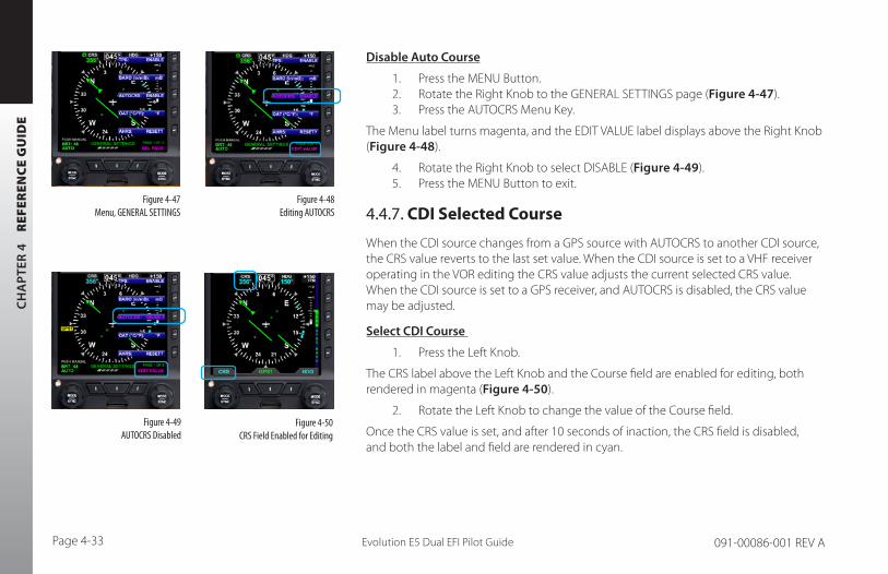
CH
AP
TER
4
REF
EREN
CE
GU
IDE
Evolution E5 Dual EFI Pilot GuidePage 4-33 091-00086-001 REV A
Disable Auto Course
1. Press the MENU Button.2. Rotate the Right Knob to the GENERAL SETTINGS page (Figure 4-47).3. Press the AUTOCRS Menu Key.
The Menu label turns magenta, and the EDIT VALUE label displays above the Right Knob (Figure 4-48).
4. Rotate the Right Knob to select DISABLE (Figure 4-49).5. Press the MENU Button to exit.
4.4.7. CDI Selected Course
When the CDI source changes from a GPS source with AUTOCRS to another CDI source, the CRS value reverts to the last set value. When the CDI source is set to a VHF receiver operating in the VOR editing the CRS value adjusts the current selected CRS value. When the CDI source is set to a GPS receiver, and AUTOCRS is disabled, the CRS value may be adjusted.
Select CDI Course
1. Press the Left Knob.
The CRS label above the Left Knob and the Course field are enabled for editing, both rendered in magenta (Figure 4-50).
2. Rotate the Left Knob to change the value of the Course field.
Once the CRS value is set, and after 10 seconds of inaction, the CRS field is disabled, and both the label and field are rendered in cyan.
Figure 4-47 Menu, GENERAL SETTINGS
Figure 4-49 AUTOCRS Disabled
Figure 4-50 CRS Field Enabled for Editing
Figure 4-48 Editing AUTOCRS
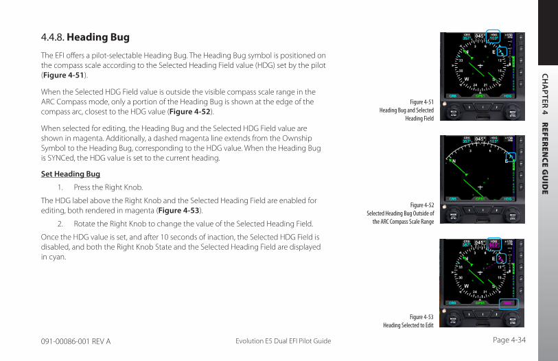
CH
AP
TER 4 R
EFEREN
CE G
UID
E
Evolution E5 Dual EFI Pilot Guide Page 4-34091-00086-001 REV A
4.4.8. Heading Bug
The EFI offers a pilot-selectable Heading Bug. The Heading Bug symbol is positioned on the compass scale according to the Selected Heading Field value (HDG) set by the pilot (Figure 4-51).
When the Selected HDG Field value is outside the visible compass scale range in the ARC Compass mode, only a portion of the Heading Bug is shown at the edge of the compass arc, closest to the HDG value (Figure 4-52).
When selected for editing, the Heading Bug and the Selected HDG Field value are shown in magenta. Additionally, a dashed magenta line extends from the Ownship Symbol to the Heading Bug, corresponding to the HDG value. When the Heading Bug is SYNCed, the HDG value is set to the current heading.
Set Heading Bug
1. Press the Right Knob.
The HDG label above the Right Knob and the Selected Heading Field are enabled for editing, both rendered in magenta (Figure 4-53).
2. Rotate the Right Knob to change the value of the Selected Heading Field.
Once the HDG value is set, and after 10 seconds of inaction, the Selected HDG Field is disabled, and both the Right Knob State and the Selected Heading Field are displayed in cyan.
Figure 4-51 Heading Bug and Selected
Heading Field
Figure 4-52 Selected Heading Bug Outside of
the ARC Compass Scale Range
Figure 4-53 Heading Selected to Edit

CH
AP
TER
4
REF
EREN
CE
GU
IDE
Evolution E5 Dual EFI Pilot GuidePage 4-35 091-00086-001 REV A
4.4.9. Aircraft Heading Display
The aircraft heading is displayed in degrees magnetic (Figure 4-54).
If the aircraft’s heading is unavailable or invalid, all heading and navigation information, including the CDI is removed and replaced with a single red X covering the entire lower display area, along with the annunciation DIRECTION INDICATOR FAIL (Figure 4-55).
4.4.10. Rate of Turn Indicator
The Rate of Turn Indicator consists of a curved white line originating from the corresponding side of the aircraft heading (i.e., a left turn indication starts on the left side of the index mark) and extends in the direction of the turn along the outer radius of the compass scale. The turn rate indication is provided for both compass modes, 360° (Figure 4-56) and ARC (Figure 4-57).
The Rate of Turn Indicator features tick marks for full and half-standard rate turns (a standard rate turn = 3° per second).
The Rate of Turn Indicator has a range of 0° – 6° per second. When the turn rate exceeds 6° per second, an arrowhead is added to the end of the tape to show that the rate of turn has exceeded the limits of the instrument.
Figure 4-54 Direction of Flight Numerical Display
Figure 4-55 Direction Indicator Fail
Figure 4-57 Rate of Turn Indicator (ARC Compass Mode)
Figure 4-56 Rate of Turn Indicator (360° Compass Mode)
NOTE The Evolution E5 Dual EFI’s Rate of Turn Indicator will be removed when operating in DEGRADED MODE.
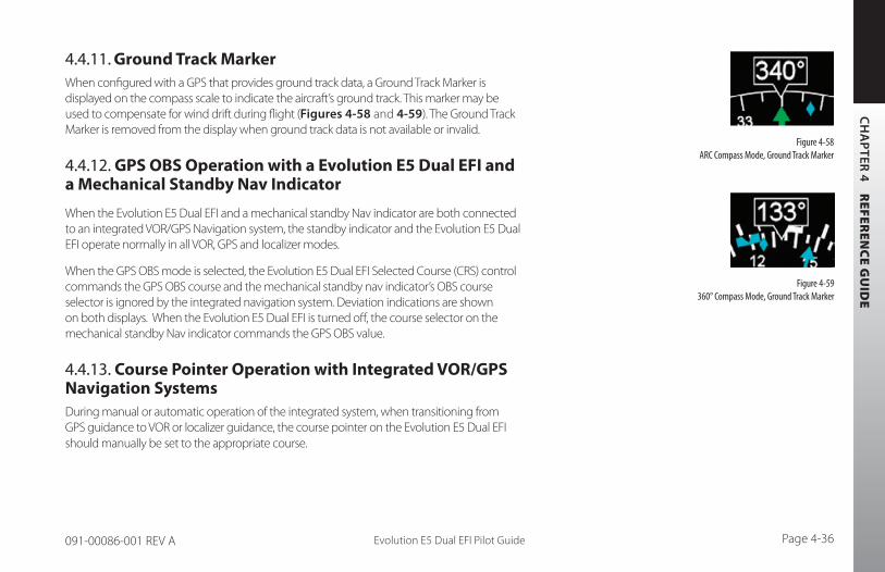
CH
AP
TER 4 R
EFEREN
CE G
UID
E
Evolution E5 Dual EFI Pilot Guide Page 4-36091-00086-001 REV A
4.4.11. Ground Track MarkerWhen configured with a GPS that provides ground track data, a Ground Track Marker is displayed on the compass scale to indicate the aircraft’s ground track. This marker may be used to compensate for wind drift during flight (Figures 4-58 and 4-59). The Ground Track Marker is removed from the display when ground track data is not available or invalid.
4.4.12. GPS OBS Operation with a Evolution E5 Dual EFI and a Mechanical Standby Nav Indicator
When the Evolution E5 Dual EFI and a mechanical standby Nav indicator are both connected to an integrated VOR/GPS Navigation system, the standby indicator and the Evolution E5 Dual EFI operate normally in all VOR, GPS and localizer modes.
When the GPS OBS mode is selected, the Evolution E5 Dual EFI Selected Course (CRS) control commands the GPS OBS course and the mechanical standby nav indicator’s OBS course selector is ignored by the integrated navigation system. Deviation indications are shown on both displays. When the Evolution E5 Dual EFI is turned off, the course selector on the mechanical standby Nav indicator commands the GPS OBS value.
4.4.13. Course Pointer Operation with Integrated VOR/GPS Navigation SystemsDuring manual or automatic operation of the integrated system, when transitioning from GPS guidance to VOR or localizer guidance, the course pointer on the Evolution E5 Dual EFI should manually be set to the appropriate course.
Figure 4-58 ARC Compass Mode, Ground Track Marker
Figure 4-59 360° Compass Mode, Ground Track Marker

CH
AP
TER
4
REF
EREN
CE
GU
IDE
Evolution E5 Dual EFI Pilot GuidePage 4-37 091-00086-001 REV A
4.5. Vertical Speed Indicator (VSI)When the 360° Compass Mode is selected, the Vertical Speed Indicator (VSI) is rendered on the right side of the Navigation Display, showing a numerical and graphical representations of vertical speed. The VSI shows the change in pressure altitude over time. The graphical display is a white VSI Tape, with the numerical value at the top (Figure 4-60). In either ARC Compass mode, only the numerical value is shown.
The VSI Tape displays rates of ±2,000 FPM while the numerical value displays rates up to ±9,990 FPM. When the vertical speed exceeds ±2,000 FPM, a triangle caps the VSI Tape (Figure 4-61).
The VSI Tape is nonlinear, giving more display area to the 0 to ±1,000 FPM range than to the ±1,000 to ±2,000 FPM range. Tick marks are presented only in the direction of the climb or descent to provide visual cues for trends. The VSI’s numerical value, tape, and scale are only shown if the aircraft is climbing or descending more than ±100 FPM. During level flight in calm air conditions, the tape, scale, and zero reference line are removed from the display. The numerical value is always enabled and shows dashes when vertical rates are out of range. If vertical speed is invalid, the Tape and numerical display are replaced with a red X and the annunciation, VSI FAIL (Figure 4-62).
1. May require optional ACU
Figure 4-60 VSI
Figure 4-61 VSI Tape Off-Scale
Figure 4-62 VSI Fail – 360° Compass Mode

CH
AP
TER 4 R
EFEREN
CE G
UID
E
Evolution E5 Dual EFI Pilot Guide Page 4-38091-00086-001 REV A
4.6. Autopilot Integration1
The Evolution E5 Dual EFI can connect with many different legacy autopilot systems that are typically found in general aviation aircraft. Autopilot integration is limited to heading and navigation modes.
When connected to an autopilot system that includes Nav couplers, the Evolution E5 Dual EFI also acts as the navigation source selector switch to the autopilot. This assures that the navigation information selected for the Evolution E5 Dual EFI is the same as that being provided to the autopilot. This arrangement also eliminates the need for external autopilot navigation source selector switches and relays that were previously used to select which navigation radio would be connected to the autopilot. Selection of autopilot modes and mode control is unaffected by the installation of the Evolution E5 Dual EFI.
The Evolution E5 Dual EFI does not currently provide vertical coupling to barometric references, such as altitude hold, vertical speed, or altitude capture.
See Section 4.6.2. Typical Autopilot Operation for more details on Evolution E5 Dual EFI operation with the autopilot systems during typical aircraft operations.
NOTE Refer to the autopilot AFMS for information on the operation of the autopilot.
1. May require optional ACU
CH
AP
TER
4
REF
EREN
CE
GU
IDE
Evolution E5 Dual EFI Pilot GuidePage 4-39 091-00086-001 REV A
4.6.1. GPS Steering (GPSS)1
GPS Steering represents a modern approach to flying between flight plan waypoints, and offers many advantages of over traditional methods of flying direct course lines between waypoints.
With traditional point-to-point navigation, the autopilot is provided with desired course and cross-track deviation information associated with the current flight leg. From there, it will maneuver the aircraft to center the needle and track the desired course. The autopilot does not anticipate upcoming course changes, nor can it fly curved flight paths without pilot assistance, and it has to recompute wind corrections following each course change. Upon reaching a waypoint, the pilot must set the course for the next leg (unless AUTOCRS is enabled, see Section 4.4.6. Auto Course), and the autopilot will then intercept and track that leg. In this type of operation, the CDI must always be set to the desired course.
With GPSS, the Evolution E5 Dual EFI can unlock the GPS Steering capability already available in many models of general aviation GPS navigators. With GPSS, the navigator continuously computes the desired bank angle to track the GPS flight plan, and outputs that information over a digital data bus. The GPS Steering command anticipates upcoming turns; this includes the turn rate and turn initiation point required to roll out centered on the next leg.
Some GPS navigators, such as the Garmin 4xx/5xxW, GTN 650/750 and Avidyne IFD440/550 series of WAAS navigators, even provide GPS Steering commands for complex procedures, such as DME arcs, holding patterns, and procedure turns allowing the autopilot to fly these maneuvers without pilot intervention. Check with your GPS manufacturer to see if your GPS supports these capabilities.
WARNING GPS Steering is a powerful automation tool that can substantially reduce pilot workload. However, using GPSS safely and effectively requires a thorough understanding of your specific aircraft installation and the interaction between the Evolution E5 Dual EFI, your GPS navigator, and your autopilot. Pilot actions required to use GPSS safely can vary significantly depending on the autopilot and GPS navigator installed, especially when used on instrument approaches, especially those with vertical guidance.
It is imperative that pilots new to GPSS gain experience with it in VFR conditions and, ideally, get dual instruction from a CFII who thoroughly understands GPSS and the autopilot and GPS navigator in your airplane before using GPSS on instrument procedures in IMC.
1. May require ACU option

CH
AP
TER 4 R
EFEREN
CE G
UID
E
Evolution E5 Dual EFI Pilot Guide Page 4-40091-00086-001 REV A
The Evolution E5 Dual EFI translates GPS Steering commands received over a digital data bus into a signal that is compatible with the autopilot Heading channel. Thus, by selecting GPSS Hot Key on the Evolution E5 Dual EFI and the Heading mode of the autopilot, the autopilot is able to fly GPSS commands.
If the connected GPS does not provide the required steering commands, the GPSS legend adjacent to the GPSS Hot Key will be rendered in gray, and it will not be possible to enable GPSS with the Hot Key.
Enable/Disable GPSS
1. Press the GPSS Hot Key to alternately enable or disable GPS Steering (Figure 4-63).
NOTE Refer to the Aircraft Flight Manual Supplement for your GPS for information about GPSS commands that may be output by that system.
NOTE When GPSS is selected on the Evolution E5 Dual EFI, the autopilot must be in Heading mode to follow the GPSS commands.
NOTE When GPSS is disabled, the autopilot will follow the Heading Bug.
Figure 4-63 GPSS Hot Key

CH
AP
TER
4
REF
EREN
CE
GU
IDE
Evolution E5 Dual EFI Pilot GuidePage 4-41 091-00086-001 REV A
When GPSS is enabled, and the autopilot is in HDG mode, the autopilot will follow the steering commands from the GPS. A GPSS enabled state will be indicated on the EFI in two locations: 1) the GPSS legend adjacent to the GPSS Hot Key will be shown in inverse green; and 2) the annunciation GPSS1 along with an inverse A, will be shown next to the HDG reference at the top of the Navigation Display, to the right of the Magnetic heading indication (Figure 4-64).
When GPSS is disabled, and the autopilot is in HDG mode, the autopilot will follow the Evolution E5 Dual EFI Heading Bug. A GPSS disabled state will be indicated on the display in two locations: 1) the GPSS legend adjacent to the GPSS Hot Key will be shown in gray; and 2) the Selected Heading Field will return. (Figure 4-65).
When the Evolution E5 Dual EFI Basemap navigation source is GPS1, enabling GPSS with the autopilot in HDG mode will cause the autopilot to track the flight plan in GPS1, and GPSS1 will be annunciated by the HDG reference at the top of the Navigation Display. See Section 4.4.5 for additional information on the relationship among the CDI navigation source and GPSS navigation source.
When using GPSS with a stand-alone VLOC receiver, or with a combined GPS/VLOC navigator (e.g., the GNS-430/530), GPSS will continue to follow the GPS output of that combined navigator, even when VLOC is selected as the Evolution E5 Dual EFI Selected CDI Navigation Source. With combined GPS/VLOC receivers, the transition from GPS to VLOC may occur automatically, depending on how that system has been configured by the pilot.
Figure 4-64 GPSS Enabled with Autopilot in HDG Mode
Figure 4-65 GPSS Disabled and Autopilot in HDG Mode

CH
AP
TER 4 R
EFEREN
CE G
UID
E
Evolution E5 Dual EFI Pilot Guide Page 4-42091-00086-001 REV A
With GPSS enabled on the Evolution E5 Dual EFI and the autopilot in HDG mode, the GPSS will steer the autopilot laterally through the flight plan using GPS, even after the GNS-430 CDI automatically switches to VLOC, and the Evolution E5 Dual EFI navigation source similarly switches to VLOC.
Several conditions can cause GPSS to be disabled automatically, losing the GPS navigator source, canceling the flight plan, etc.). If this happens, the Evolution E5 Dual EFI will send a Wings Level command to the autopilot when in HDG mode, the GPSS Hot Key will annunciate the condition by showing GPSS in inverse amber, and the GPSS# and inverse A annunciation at the top of the Navigation Display will be shown with a red slash. (See Figure 4-66). To re-engage GPSS, select a valid GPS navigation source (with valid flight plan or direct-to selection on the GPS navigator), and then press the GPSS Hot Key. If a valid GPSS signal cannot be restored, pressing the GPSS Hot Key will cancel GPSS mode and restore the Heading Bug’s output to the autopilot. More detail on these abnormal conditions, and corrective pilot actions, can be found in Chapter 6, Expanded Emergency and Abnormal Procedures. See also Chapter 4, Section 4.7.3. Typical Autopilot Operations.
WARNING It is your responsibility as Pilot in Command to ensure that you are familiar with the operation of all installed equipment. Operation of the Evolution E5 Dual EFI in IMC conditions should not be attempted unless you are proficient in its use and operation, as described herein.
Figure 4-66GPSS Automatically
Disabled — Wings Level Mode
1. May require ACU option

CH
AP
TER
4
REF
EREN
CE
GU
IDE
Evolution E5 Dual EFI Pilot GuidePage 4-43 091-00086-001 REV A
4.6.2. Typical Autopilot Operations1
Whenever the Evolution E5 Dual EFI’s installed configuration includes connections to GPS, VLOC, and autopilot systems, it acts as a data conduit between the navigators and the autopilot. This enables any compatible navigator to be coupled to the autopilot.
HDG Mode Operation – Heading Bug Steering
1. Set the Heading Bug to the desired heading (Section 4.4.8).2. Verify that GPSS is not selected. 3. Select the autopilot’s Heading (HDG) mode. 4. Engage the autopilot and verify that the autopilot turns the aircraft to the
selected heading.
HDG Mode Operation – GPS Steering (GPSS)
1. Couple the Evolution E5 Dual EFI CDI to a GPS navigation source with an active flight plan.
2. Enable GPSS by pressing the GPSS Hot Key.3. Select the autopilot’s Heading (HDG) mode.4. Engage the autopilot and verify that the autopilot turns the aircraft to follow
the GPS flight plan.
NAV Mode Operation – VLOC Navigation
1. Using the CDI Source Select button, couple a tuned/valid VLOC radio to the Evolution E5 Dual EFI CDI and adjust the Course Pointer (CRS) to a value that will intercept the course.
2. Set the Heading Bug 3. Engage the autopilot in Heading (HDG) mode and verify that the aircraft turns
to the desired heading.
NOTE When GPSS is enabled, the Heading Bug is not coupled to the autopilot. To connect the Heading Bug to the autopilot, disable GPSS with the GPSS Hot Key.
NOTE Refer to the autopilot systems Aircraft Flight Manual Supplement and/or POH for details regarding use and operation of the autopilot system.
Examples here are provided for reference only, actual operation may vary depending on the autopilot system installed in your aircraft.
NOTE With the autopilot in HDG mode, if GPSS is automatically disabled, the autopilot will roll wings level; it will not follow the Heading Bug.
CH
AP
TER 4 R
EFEREN
CE G
UID
E
Evolution E5 Dual EFI Pilot Guide Page 4-44091-00086-001 REV A
4. If your autopilot supports automatic Heading to Navigation mode transitions, arm Navigation capture on the autopilot by selecting its Navigation (NAV) mode. Otherwise, select the autopilot’s Navigation (NAV) mode when the autopilot’s navigation signal capture criteria are satisfied (see your autopilot AFMS for more information).
5. Monitor the CDI deflection and verify that, upon intercepting the desired course, the autopilot modes transition appropriately and the autopilot tracks the desired course.
NAV Mode Operation – GPS Navigation1. With a valid flight plan programmed and active in the GPS, use the CDI
Source Select button to couple the GPS to the Evolution E5 Dual EFI (see Section 4.4.5.).
2. If AUTOCRS is disabled, set the Course Pointer to the desired course (CRS) (see Section 4.4.7.), or enable AUTOCRS (see Section 4.4.6.).
3. With GPSS disabled, set the Heading Bug (see Section 4.4.8.) to a value that will intercept the active leg of the flight plan, or enable GPSS via the GPSS Hot Key.
4. Engage the autopilot in Heading (HDG) mode and verify that the aircraft turns to a heading to intercept the active leg of the flight plan.
5. If your autopilot supports automatic heading to nav mode transitions, arm the navigation capture on the autopilot by selecting its Navigation (NAV) mode. Otherwise, select the autopilot Navigation (NAV) mode when the autopilot navigation signal capture criteria are satisfied (see your autopilot AFMS for more information).
6. Monitor the CDI deflection and verify that, upon intercepting the flight plan leg, the autopilot modes transition appropriately and the autopilot tracks the desired course
NOTE The autopilot must be in Heading (HDG) Mode to receive GPSS signals from the Evolution E5 Dual EFI.
NOTE When using an integrated GPS/VLOC navigator, select VLOC or GPS with the CDI source button on the GPS select until the desired CDI Navigation Source is shown on the Evolution E5 Dual EFI (See Section 4.4.5.)
NOTE Not all autopilots operate in the manner described here for intercepting courses. See the AFMS for your autopilot installation to understand how to adapt these example procedures to your particular autopilot.

CH
AP
TER
5
CU
STO
MIZ
ING
TH
E E
VO
LUT
ION
E5
DU
AL
EFI
Evolution E5 Dual EFI Pilot GuidePage 5-1 091-00086-001 REV A Evolution E5 Dual EFI Pilot Guide Page 5-2091-00086-001 REV A
Chapter 5Customizing the Evolution E5 Dual EFI
5.1. Menu OverviewThe following tables and figures provide a brief overview of each menu page and its menu options.
KEY DESCRIPTION OPTIONS
Displays Airspeed and Altitude Tapes 1 DISABLE or ENABLE
Barometer Pressure Setting Units of Measure in or mB
Auto Course Select DISABLE or ENABLE
Outside Air Temperature Units of Measure °C or °F
AHRS Reset to re-initialize the current sensor data
Action
Table 5-1 Menu – GENERAL SETTINGS
Figure 5-1 GENERAL SETTINGS A

CH
AP
TER 5 C
US
TOM
IZIN
G T
HE E
VO
LUT
ION
E5 D
UA
L EFI
Evolution E5 Dual EFI Pilot GuidePage 5-1 091-00086-001 REV A Evolution E5 Dual EFI Pilot Guide Page 5-2091-00086-001 REV A
Figure 5-2 VSPEEDS A
Figure 5-3 VSPEEDS B
KEY DESCRIPTION OPTIONS
VSPEEDS DISABLE or ENABLE
Va 0 to 450 or LOCKED
Vbg 0 to 450 or LOCKED
Vref 0 to 450 or LOCKED
Vr 0 to 450 or LOCKED
Table 5-2Menu –VSPEEDS A
KEY DESCRIPTION OPTIONS
Vx 0 to 450 or LOCKED
Vy 0 to 450 or LOCKED
Vlo 0 to 450 or LOCKED
Vle 0 to 450 or LOCKED
Table 5-3
Menu – VSPEEDS B

CH
AP
TER
5
CU
STO
MIZ
ING
TH
E E
VO
LUT
ION
E5
DU
AL
EFI
Evolution E5 Dual EFI Pilot GuidePage 5-3 091-00086-001 REV A Evolution E5 Dual EFI Pilot Guide Page 5-4091-00086-001 REV A
Figure 5-4 POWER SETTINGS
NOTE For external/battery power control, the legend of the current power source is shown in green; pressing the associated menu key will perform no action. The legend of an available power source is shown in white, and pressing the associated menu key changes input power to that power source.
KEY DESCRIPTION OPTIONS
Operating from or Switch to Battery Power. Green when current state (Pressing key performs no action). White if selection is possible.
Status or Action
Operating from or Switch to External Power. Green when current state (Pressing key performs no action). White if selection is possible.
Status or Action
Restart or shutdown. Action
External Power Source Voltage. Displays voltage level of input power. Status Only
Battery Status Description
Status Only
##% Displays battery % charge.
CHARGING
The battery has sufficient voltage and can accept charging, aircraft power is available, and the temperature sensor is within limits (0°C to +55°C).
FAILED The battery voltage is less than 6 volts; i.e. insufficient for charging.
READY
The connected battery and battery voltage are satisfactory, but the temperature limits (0°C to +55°C) that will permit charging have been exceeded.
Table 5-4 Menu – POWER SETTINGS
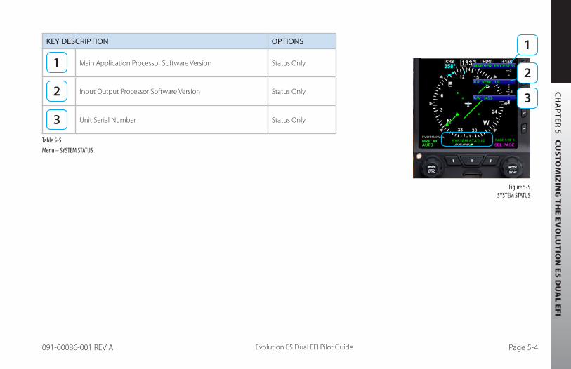
CH
AP
TER 5 C
US
TOM
IZIN
G T
HE E
VO
LUT
ION
E5 D
UA
L EFI
Evolution E5 Dual EFI Pilot GuidePage 5-3 091-00086-001 REV A Evolution E5 Dual EFI Pilot Guide Page 5-4091-00086-001 REV A
Figure 5-5 SYSTEM STATUS
KEY DESCRIPTION OPTIONS
Main Application Processor Software Version Status Only
Input Output Processor Software Version Status Only
Unit Serial Number Status Only
Table 5-5
Menu – SYSTEM STATUS
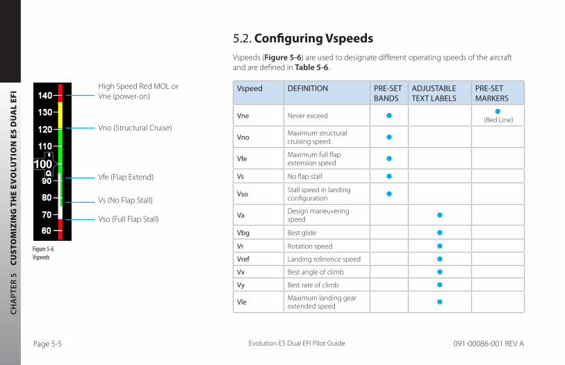
CH
AP
TER
5
CU
STO
MIZ
ING
TH
E E
VO
LUT
ION
E5
DU
AL
EFI
Evolution E5 Dual EFI Pilot GuidePage 5-5 091-00086-001 REV A Evolution E5 Dual EFI Pilot Guide Page 5-6091-00086-001 REV A
5.2. Configuring VspeedsVspeeds (Figure 5-6) are used to designate different operating speeds of the aircraft and are defined in Table 5-6.
Vspeed DEFINITION PRE-SET BANDS
ADJUSTABLE TEXT LABELS
PRE-SET MARKERS
Vne Never exceed (Red Line)
Vno Maximum structural cruising speed
Vfe Maximum full flap extension speed
Vs No flap stall
Vso Stall speed in landing configuration
Va Design maneuvering speed
Vbg Best glide
Vr Rotation speed
Vref Landing reference speed
Vx Best angle of climb
Vy Best rate of climb
Vle Maximum landing gear extended speed
Figure 5-6Vspeeds
High Speed Red MOL or Vne (power-on)
Vno (Structural Cruise)
Vfe (Flap Extend)
Vs (No Flap Stall)
Vso (Full Flap Stall)

CH
AP
TER 5 C
US
TOM
IZIN
G T
HE E
VO
LUT
ION
E5 D
UA
L EFI
Evolution E5 Dual EFI Pilot GuidePage 5-5 091-00086-001 REV A Evolution E5 Dual EFI Pilot Guide Page 5-6091-00086-001 REV A
Vspeed DEFINITION PRE-SET BANDS
ADJUSTABLE TEXT LABELS
PRE-SET MARKERS
Vlo Maximum landing gear operating speed
Vmc (Multi-engine) Single-engine minimum control airspeed
(Red Line)
Vyse (Multi-engine) Best single-engine rate of climb
(Blue Line)
Maximum initial flap extension speed
Table 5-6 Vspeed Definitions
The Evolution E5 Dual EFI uses color speed bands, color speed markers, and textual labels to help the pilot recall Vspeed settings and limits. The speed band markings are determined by the Federal Regulations and correspond to the aircraft operating speeds that are identified in the Aircraft Flight Manual. They have a range between two speeds that are pre-set at installation as outlined in Table 5-7 and shown in (Figure 5-7).
Speed markers are also pre-set during installation, indicating important aircraft-specific speeds, where applicable. The textual Vspeed labels are made pilot adjustable or locked during the installation.
NOTE Setting the value of the white triangle, Vyse, and Vmc markers to zero (0) during installation disables the markers. Setting any of the adjustable Vspeed values to zero (0) disables the associated label.
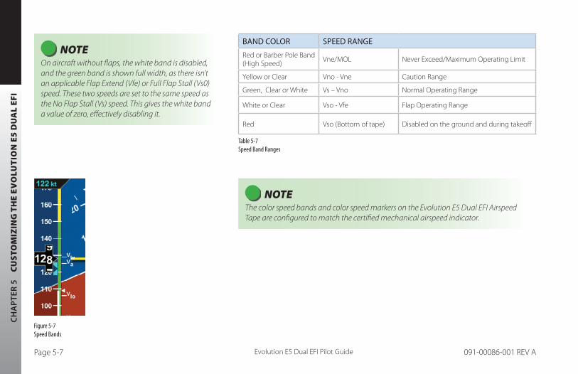
CH
AP
TER
5
CU
STO
MIZ
ING
TH
E E
VO
LUT
ION
E5
DU
AL
EFI
Evolution E5 Dual EFI Pilot GuidePage 5-7 091-00086-001 REV A Evolution E5 Dual EFI Pilot Guide Page 5-8091-00086-001 REV A
BAND COLOR SPEED RANGE
Red or Barber Pole Band (High Speed) Vne/MOL Never Exceed/Maximum Operating Limit
Yellow or Clear Vno - Vne Caution Range
Green, Clear or White Vs – Vno Normal Operating Range
White or Clear Vso - Vfe Flap Operating Range
Red Vso (Bottom of tape) Disabled on the ground and during takeoff
Table 5-7 Speed Band Ranges
Figure 5-7 Speed Bands
NOTE On aircraft without flaps, the white band is disabled, and the green band is shown full width, as there isn’t an applicable Flap Extend (Vfe) or Full Flap Stall (Vs0) speed. These two speeds are set to the same speed as the No Flap Stall (Vs) speed. This gives the white band a value of zero, effectively disabling it.
NOTE The color speed bands and color speed markers on the Evolution E5 Dual EFI Airspeed Tape are configured to match the certified mechanical airspeed indicator.

CH
AP
TER 5 C
US
TOM
IZIN
G T
HE E
VO
LUT
ION
E5 D
UA
L EFI
Evolution E5 Dual EFI Pilot GuidePage 5-7 091-00086-001 REV A Evolution E5 Dual EFI Pilot Guide Page 5-8091-00086-001 REV A
On aircraft with flaps, setting the upper and lower thresholds of the white and/or yellow bands to the same value disables the applicable band. When disabled, the band does not display.
When using the Vspeed textual markers, the pilot must first ENABLE the display of the markers and then set values for each Vspeed. The value range for Vspeed textual markers is 0 – 450 or LOCKED. The default setting is 0 unless previously set to another value. When the value is 0, the Vspeed is individually disabled, and the marker is not shown on the Airspeed Tape. Once the values are set, the pilot can choose to disable all the Vspeed textual markers to declutter the Airspeed Tape.
Display or Hide the Vspeed Textual Markers on the Airspeed Tape
1. Press the MENU Button. 2. Rotate the Right Knob to the VSPEEDS A Menu page (Figure 5-8).3. Press the VSPEEDS Menu Key. The Menu label turns magenta, and the EDIT VALUE label displays above
the Right Knob (Figure 5-9).4. Rotate the Right Knob to select ENABLE or DISABLE (Figure 5-10). ENABLE will display the Vspeeds on the Airspeed Tape and DISABLE will
hide the Vspeeds to declutter the Airspeed Tape5. Press the MENU Button to exit.
Figure 5-10 VSPEEDS Disabled
Figure 5-9 Editing VSPEEDS
Figure 5-8 VSPEEDS A

CH
AP
TER
5
CU
STO
MIZ
ING
TH
E E
VO
LUT
ION
E5
DU
AL
EFI
Evolution E5 Dual EFI Pilot GuidePage 5-9 091-00086-001 REV A Evolution E5 Dual EFI Pilot Guide Page 5-10091-00086-001 REV A
Set Textual Vspeed Labels
1. Press the MENU Button. 2. Rotate the Right Knob to the appropriate Vspeed Menu page (Figure 5-11).3. Press the appropriate Vspeed Menu Key. The Menu label turns magenta, and the EDIT VALUE label displays above the
Right Knob (Figure 5-12).4. Rotate the Right Knob to the desired value (Figure 5-13).5. Select another Menu Key to edit another Vspeed or press the MENU Button
to exit.Figure 5-11 VSPEEDS A
Figure 5-12 Editing Va Vspeed
Figure 5-13 Va Vspeed Set With New Value
NOTE A typical installation sets the Airspeed Textual Markers to UNLOCKED, allowing the pilot to edit the indicated Vspeed labels. If the Vspeed setting was LOCKED during installation, no pilot adjustment is allowed.
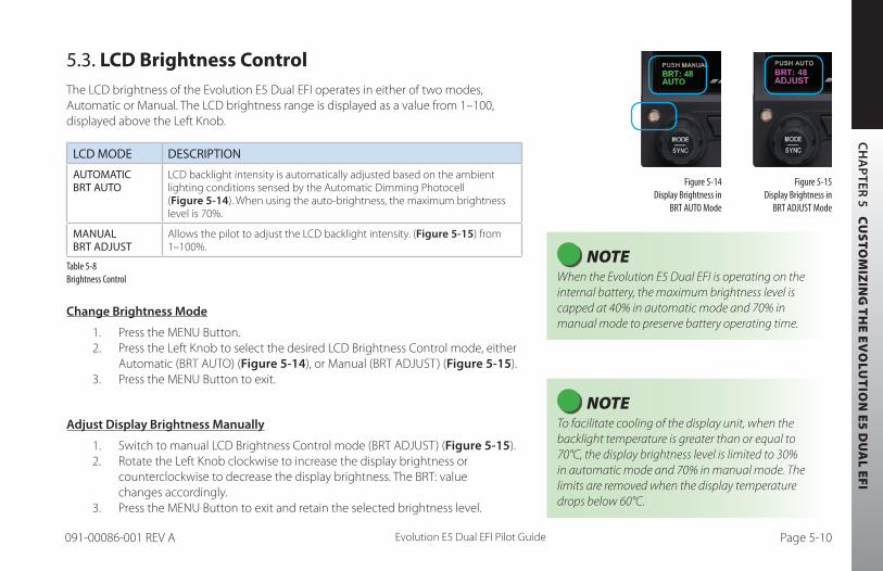
CH
AP
TER 5 C
US
TOM
IZIN
G T
HE E
VO
LUT
ION
E5 D
UA
L EFI
Evolution E5 Dual EFI Pilot GuidePage 5-9 091-00086-001 REV A Evolution E5 Dual EFI Pilot Guide Page 5-10091-00086-001 REV A
5.3. LCD Brightness ControlThe LCD brightness of the Evolution E5 Dual EFI operates in either of two modes, Automatic or Manual. The LCD brightness range is displayed as a value from 1–100, displayed above the Left Knob.
LCD MODE DESCRIPTION
AUTOMATIC BRT AUTO
LCD backlight intensity is automatically adjusted based on the ambient lighting conditions sensed by the Automatic Dimming Photocell (Figure 5-14). When using the auto-brightness, the maximum brightness level is 70%.
MANUAL BRT ADJUST
Allows the pilot to adjust the LCD backlight intensity. (Figure 5-15) from 1–100%.
Table 5-8 Brightness Control
Change Brightness Mode
1. Press the MENU Button.2. Press the Left Knob to select the desired LCD Brightness Control mode, either
Automatic (BRT AUTO) (Figure 5-14), or Manual (BRT ADJUST) (Figure 5-15). 3. Press the MENU Button to exit.
Adjust Display Brightness Manually
1. Switch to manual LCD Brightness Control mode (BRT ADJUST) (Figure 5-15).2. Rotate the Left Knob clockwise to increase the display brightness or
counterclockwise to decrease the display brightness. The BRT: value changes accordingly.
3. Press the MENU Button to exit and retain the selected brightness level.
Figure 5-15 Display Brightness in
BRT ADJUST Mode
Figure 5-14 Display Brightness in
BRT AUTO Mode
NOTE When the Evolution E5 Dual EFI is operating on the internal battery, the maximum brightness level is capped at 40% in automatic mode and 70% in manual mode to preserve battery operating time.
NOTE To facilitate cooling of the display unit, when the backlight temperature is greater than or equal to 70°C, the display brightness level is limited to 30% in automatic mode and 70% in manual mode. The limits are removed when the display temperature drops below 60°C.

Evolution E5 Dual EFI Pilot GuidePage 6-1 091-00086-001 REV A Evolution E5 Dual EFI Pilot Guide Page 6-2091-00086-001 REV A
CH
APT
ER 6
EX
PAND
ED E
MER
GENC
Y AN
D AB
NORM
AL P
ROCE
DURE
S
Chapter 6
Expanded Emergency and Abnormal Procedures
This section supplements and provides an expanded description of the emergency and abnormal procedures included in the FAA-approved Aircraft Flight Manual Supplement. The information provided here is intended to provide additional background information to enhance the pilot’s understanding of the emergency and abnormal conditions and the associated procedures provided in the AFMS. This pilot guide is provided for supplementary purposes only. The approved cockpit reference for in-flight use is the AFMS. Both the Pilot Guide and the AFMS must be immediately available to the pilot at all times in flight. In the event of any conflict between this document and the FAA-approved AFMS, the AFMS instructions must be followed.

Evolution E5 Dual EFI Pilot GuidePage 6-1 091-00086-001 REV A Evolution E5 Dual EFI Pilot Guide Page 6-2091-00086-001 REV A
CH
APTER 6 EXPANDED EM
ERGENCY AND ABNORMAL PROCEDURES
6.1. Pitot/Static System BlockageA pitot line blockage will result in the airspeed indicator behaving like an altimeter when the aircraft’s altitude changes, and it will not respond to airspeed changes. A pitot line blockage can also affect the Evolution E5 Dual EFI’s attitude indication.
A static line blockage will result in altitude remaining fixed and a zero vertical speed despite aircraft pitch and/or power setting changes. In addition, IAS indications will be incorrect if the static line is blocked. Errors will typically be noticed during climbs or descents. When descending, ambient pressure increases which will result in the indicated airspeed reading more than the actual airspeed. The opposite effect will be observed in a climb. A static line blockage can also affect the Evolution E5 Dual EFI’s attitude indication.
Indication of an obstructed pitot system is provided when the Evolution E5 Dual EFI’s indicated airspeed is less than 30 KIAS (35 mph) and GPS ground speed is greater than 50 kts (58 mph). Initially a “CROSS CHECK ATTITUDE” annunciation will appear as IAS bleeds off. Then an “ATTITUDE DEGRADED” annunciation appears above the aircraft reference symbol (Figure 6-1). At this point the IAS part of the AHRS solution is replaced by GPS ground speed. Both the attitude and directional gyro functions of the Evolution E5 Dual EFI will continue to function during normal IFR type maneuvering. However, both the Rate of Turn and Slip indicators will be removed. If there is a subsequent failure of the GPS system, then attitude and heading instruments are replaced with red Xs and textual annunciations to indicate their failure. In this case, an amber CHECK PITOT HEAT annunciation accompanies the ATTITUDE FAIL annunciation. When the pitot obstruction is subsequently removed and indicated airspeed ≥ 30 KIAS (35 mph), the CHECK PITOT HEAT annunciation will be removed in 15 seconds. This indicates that the Evolution E5 Dual EFI is performing an automatic AHRS reset in the background. No pilot action is required to reset the system.
Figure 6-1 Degraded Mode

Evolution E5 Dual EFI Pilot GuidePage 6-3 091-00086-001 REV A Evolution E5 Dual EFI Pilot Guide Page 6-4091-00086-001 REV A
CH
APT
ER 6
EX
PAND
ED E
MER
GENC
Y AN
D AB
NORM
AL P
ROCE
DURE
S
Blocked Pitot or Static Line Suspected
1. Turn Pitot heat ON 2. Open the Alternate Static Source3. Refer to alternate, airspeed, altitude, and heading sources for primary
flight information4. Consider exiting IMC5. Land as soon as practicable
6.1.1. Identifying and Handling Suspected Pitot and/or Static System Failures
Blocked pitot and/or static system ports will degrade the Evolution E5 Dual EFI’s attitude solution. Therefore, the pilot must be especially vigilant about verifying proper operation of the pitot and static systems both before and during flight.
It is important to check the pitot tube and static system ports, and to verify pitot heater performance, as part of a thorough pre-flight inspection, especially when anticipating flight in low IMC.
On takeoff roll, it is good practice to note and call out “airspeeds alive” when the airspeed indicators (both primary and backup) begin moving and to compare and call out readings at a pre-determined airspeed close to, but before rotation speed (e.g. “60 knots cross check”), consciously noting the performance on each takeoff. If the airspeed indicators do not come “alive” when they usually do or whenever there is a significant difference between the primary and backup indicators and sufficient runway is remaining, aborting the takeoff may be a prudent decision. Follow the Flight Manual procedures for your aircraft.

Evolution E5 Dual EFI Pilot GuidePage 6-3 091-00086-001 REV A Evolution E5 Dual EFI Pilot Guide Page 6-4091-00086-001 REV A
CH
APTER 6 EXPANDED EM
ERGENCY AND ABNORMAL PROCEDURES
On the initial climb-out after takeoff, it is also good practice to note and call out passing through a pre-determined altitude above ground level (AGL) a couple of minutes after takeoff and ideally before entering the clouds (e.g., “2,000 feet”). If your primary and backup instruments are not showing the altitude and airspeed you normally expect to see at that point, you might have partially blocked static system ports. This AGL check and call-out is also a good time to verify that no fuel is siphoning out from the fuel caps, etc. If indications suggest a static system blockage, try switching to an alternate static air source and consider landing to correct the problem.
In flight, if airspeed or altitude anomalies consistent with an obstructed pitot or static line are observed, the pilot should recognize that the Evolution E5 Dual EFI’s attitude indication will soon be degraded. If in IMC, immediately turn pitot heat ON if icing is suspected.
If the pitot tube becomes blocked in flight, the most common cause is icing. In-flight indications of a blocked pitot tube are typically:
1. All airspeed indicators incorrectly show zero (or close to zero);
Or
2. Airspeed in level flight does not change in response to changes in power or drag and airspeed indications act like an altimeter (decreasing in a descent and increasing in a climb, exactly the opposite of normal behavior).

Evolution E5 Dual EFI Pilot GuidePage 6-5 091-00086-001 REV A Evolution E5 Dual EFI Pilot Guide Page 6-6091-00086-001 REV A
CH
APT
ER 6
EX
PAND
ED E
MER
GENC
Y AN
D AB
NORM
AL P
ROCE
DURE
S
Airspeed going to zero is by far the most common symptom of a blocked pitot tube.
If you see either of these indications of a blocked pitot tube, the first thing to do is turn on the pitot heat to remove any ice blockage. This will quickly restore the normal attitude and airspeed indications on the Evolution E5 Dual EFI systems (it takes about 40 seconds to recover after the pitot pressure is restored).
If in flight you suspect blocked static ports (probably due to icing), try switching to the alternate static air source. If the static air sources are blocked, recognize that the readout from the transponder and reports from ATC will be in error because of the blocked static system.
In the event of a pitot/static system failure, the Evolution E5 Dual EFI will continue to provide accurate attitude and heading solutions during typical IFR type maneuvering to include holds and both precision and non-precision type approaches.
If GPS altitude is available on your GPS navigator, become familiar with how the GPS altitude is displayed. Although it can be in error, it might be your only source of altitude information (WAAS GPS altitude is reasonably accurate).
Evolution E5 Dual EFI Pilot GuidePage 6-5 091-00086-001 REV A Evolution E5 Dual EFI Pilot Guide Page 6-6091-00086-001 REV A
CH
APTER 6 EXPANDED EM
ERGENCY AND ABNORMAL PROCEDURES
6.2. Frequent or Persistent CROSS CHECK ATTITUDE Annunciation Refer to alternate airspeed, altitude, and heading sources for primary flight information. Consider the following:
CROSS CHECK ATTITUDE
1. Turn Pitot heat ON. 2. Consider exiting IMC.3. Land as soon as practicable
For a detailed explanation of when and why the Evolution E5 Dual EFI may display a CROSS CHECK ATTITUDE annunciation, either momentarily or persistently, see Chapter 4, Section 4.1. Air Data, Attitude and Heading Reference System (ADAHRS).
6.3. Difference Detected Between the Evolution E5 Dual EFI and Mechanical IndicatorsOnce diagnosed, ensure the correct source is the only one referenced during the remainder of the flight.
Compare Alternate Sources of Available Airspeed and Attitude
1. Compare all available sources of airspeed, and attitude information to diagnose a faulty indicator.
2. Consider exiting IMC.3. Land as soon as practicable .
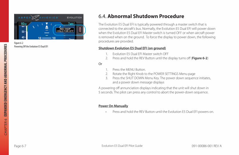
Evolution E5 Dual EFI Pilot GuidePage 6-7 091-00086-001 REV A Evolution E5 Dual EFI Pilot Guide Page 6-8091-00086-001 REV A
CH
APT
ER 6
EX
PAND
ED E
MER
GENC
Y AN
D AB
NORM
AL P
ROCE
DURE
S
6.4. Abnormal Shutdown ProcedureThe Evolution E5 Dual EFI is typically powered through a master switch that is connected to the aircraft’s bus. Normally, the Evolution E5 Dual EFI will power down when the Evolution E5 Dual EFI Master switch is turned OFF or when aircraft power is removed when on the ground. To force the display to power down, the following procedures are provided.
Shutdown Evolution E5 Dual EFI (on ground)
1. Evolution E5 Dual EFI Master switch OFF2. Press and hold the REV Button until the display turns off (Figure 6-2)
Or
1. Press the MENU Button.2. Rotate the Right Knob to the POWER SETTINGS Menu page3. Press the SHUT DOWN Menu Key. The power down sequence initiates,
and a power down message displays
A powering off annunciation displays indicating that the unit will shut down in 5 seconds. The pilot can press any control to abort the power-down sequence.
Power On Manually
• Press and hold the REV Button until the Evolution E5 Dual EFI powers on.
Figure 6-2 Powering Off the Evolution E5 Dual EFI
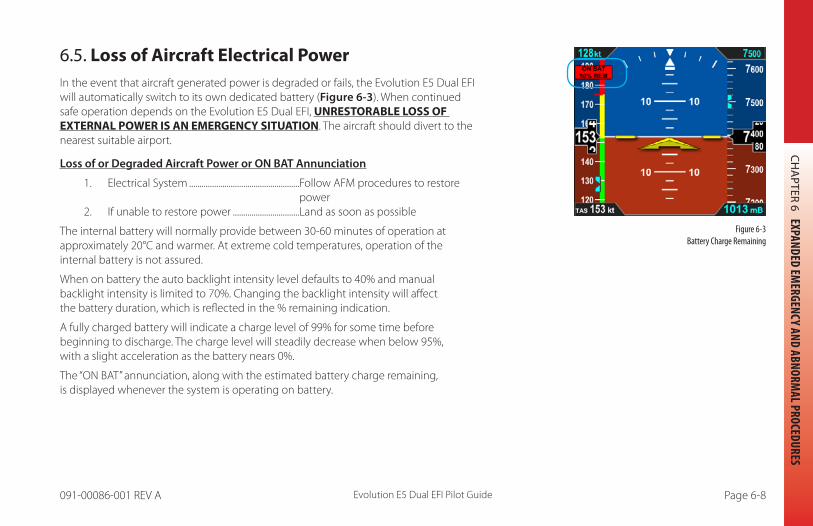
Evolution E5 Dual EFI Pilot GuidePage 6-7 091-00086-001 REV A Evolution E5 Dual EFI Pilot Guide Page 6-8091-00086-001 REV A
CH
APTER 6 EXPANDED EM
ERGENCY AND ABNORMAL PROCEDURES
6.5. Loss of Aircraft Electrical Power In the event that aircraft generated power is degraded or fails, the Evolution E5 Dual EFI will automatically switch to its own dedicated battery (Figure 6-3). When continued safe operation depends on the Evolution E5 Dual EFI, UNRESTORABLE LOSS OF EXTERNAL POWER IS AN EMERGENCY SITUATION. The aircraft should divert to the nearest suitable airport.
Loss of or Degraded Aircraft Power or ON BAT Annunciation
1. Electrical System .....................................................Follow AFM procedures to restorepower
2. If unable to restore power ................................Land as soon as possible
The internal battery will normally provide between 30-60 minutes of operation at approximately 20°C and warmer. At extreme cold temperatures, operation of the internal battery is not assured.
When on battery the auto backlight intensity level defaults to 40% and manual backlight intensity is limited to 70%. Changing the backlight intensity will affect the battery duration, which is reflected in the % remaining indication.
A fully charged battery will indicate a charge level of 99% for some time before beginning to discharge. The charge level will steadily decrease when below 95%, with a slight acceleration as the battery nears 0%.
The “ON BAT” annunciation, along with the estimated battery charge remaining, is displayed whenever the system is operating on battery.
Figure 6-3 Battery Charge Remaining

Evolution E5 Dual EFI Pilot GuidePage 6-9 091-00086-001 REV A Evolution E5 Dual EFI Pilot Guide Page 6-10091-00086-001 REV A
CH
APT
ER 6
EX
PAND
ED E
MER
GENC
Y AN
D AB
NORM
AL P
ROCE
DURE
S
6.5.1. Overvoltage Protection
In the event of an overvoltage condition in the aircraft’s electrical system, (greater than 33 volts) the Evolution E5 Dual EFI will automatically switch to its battery power and continue to operate without any pilot action. Operation from the aircraft electrical system will not be possible while the overvoltage condition is present. When aircraft power decreases below 33 volts, pilot action is required to manually switch from the Evolution E5 Dual EFI battery power.
Restore Aircraft Power to the Evolution E5 Dual EFI
1. Press the MENU Button and rotate the Right Knob to the POWER Settings page
2. Press the EXT PWR Menu Key3. Press the MENU Button to exit

Evolution E5 Dual EFI Pilot GuidePage 6-9 091-00086-001 REV A Evolution E5 Dual EFI Pilot Guide Page 6-10091-00086-001 REV A
CH
APTER 6 EXPANDED EM
ERGENCY AND ABNORMAL PROCEDURES
NOTE When operating on the internal battery, the display backlight intensity is limited to a value of 70.
NOTE Setting the brightness to a value of greater than 40% will reduce the battery operation time to less than 30 minutes.
CAUTION During situations where a high electrical demand is placed on the aircraft electrical system, electrical transients that cause aircraft voltage to drop below 9.0V momentarily or 12.3V for 2 minutes (14V electrical system) or 18.0V momentarily or 24.6V for 2 minutes (28V electrical system) will cause the Evolution E5 Dual EFI display to automatically switch to its internal battery. This will be accompanied by an ON BAT annunciation. The ON BAT annunciation should extinguish shortly after the electric transient demand goes away. If the ON BAT annunciation does not extinguish, then an aircraft power source failure has most likely occurred.
WARNING When fully charged, the internal battery will power the Evolution E5 Dual EFI to provide ADAHRS for a minimum of 30 minutes in temperature extremes and much longer in normal operating temperatures (Refer to the AFMS). When continued safe operation depends on the Evolution E5 Dual EFI’s primary flight data, UNRESTORABLE LOSS OF EXTERNAL POWER IS AN EMERGENCY SITUATION. The pilot should follow the electrical failure checklist in the Aircraft Flight Manual land as soon as possible.

Evolution E5 Dual EFI Pilot GuidePage 6-11 091-00086-001 REV A Evolution E5 Dual EFI Pilot Guide Page 6-12091-00086-001 REV A
CH
APT
ER 6
EX
PAND
ED E
MER
GENC
Y AN
D AB
NORM
AL P
ROCE
DURE
S
6.6. Power OverrideIn the event that the pilot wishes to override the Evolution E5 Dual EFI’s automatic power configuration, proceed as follows:
Power Override
1. MENU .............................................................................“POWER SETTINGS” Page
To switch FROM aircraft power to Internal Battery:
2. “BATTERY” LINE SELECT KEY ..............................PRESS
To switch FROM internal Battery TO aircraft power:
3. “EXT PWR” LINE SELECT KEY .............................PRESS
View External Voltage Status
1. Press the MENU Button.2. Rotate the Right Knob to the POWER SETTINGS Menu displays.3. The EXT PWR Menu Key (Figure 6-4) displays the external power voltage.4. Press the MENU Button to exit.
View Internal Battery Status
1. Press the MENU Button.2. Rotate the Right Knob to the POWER SETTINGS Menu displays.3. The BAT Menu Key (Figure 6-5) displays the current Battery Status as either
Charging or a Percentage of Charge.4. Press the MENU Button to exit.
NOTE When airborne, if the Evolution E5 Dual EFI’s input voltage is below the 12.8V (14V Electrical System) or 25.6V (28V Electrical System) automatic battery transition threshold, and EXT PWR is selected through the POWER SETTINGS Menu, the Evolution E5 Dual EFI will automatically remain connected to its internal battery.
Figure 6-4 External Power Voltage Status
Figure 6-5 Battery Status
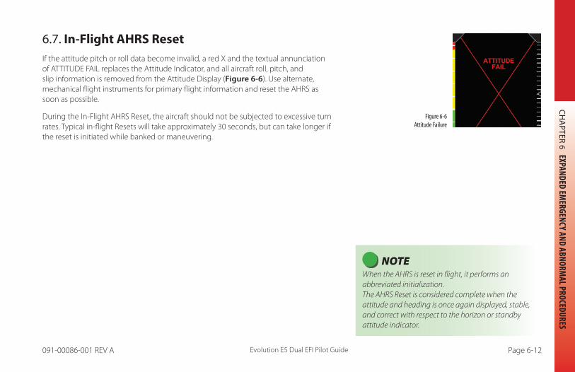
Evolution E5 Dual EFI Pilot GuidePage 6-11 091-00086-001 REV A Evolution E5 Dual EFI Pilot Guide Page 6-12091-00086-001 REV A
CH
APTER 6 EXPANDED EM
ERGENCY AND ABNORMAL PROCEDURES
6.7. In-Flight AHRS ResetIf the attitude pitch or roll data become invalid, a red X and the textual annunciation of ATTITUDE FAIL replaces the Attitude Indicator, and all aircraft roll, pitch, and slip information is removed from the Attitude Display (Figure 6-6). Use alternate, mechanical flight instruments for primary flight information and reset the AHRS as soon as possible.
During the In-Flight AHRS Reset, the aircraft should not be subjected to excessive turn rates. Typical in-flight Resets will take approximately 30 seconds, but can take longer if the reset is initiated while banked or maneuvering.
Figure 6-6 Attitude Failure
NOTE When the AHRS is reset in flight, it performs an abbreviated initialization.The AHRS Reset is considered complete when the attitude and heading is once again displayed, stable, and correct with respect to the horizon or standby attitude indicator.

Evolution E5 Dual EFI Pilot GuidePage 6-13 091-00086-001 REV A Evolution E5 Dual EFI Pilot Guide Page 6-14091-00086-001 REV A
CH
APT
ER 6
EX
PAND
ED E
MER
GENC
Y AN
D AB
NORM
AL P
ROCE
DURE
S
Perform an In-Flight AHRS Reset
1. Maintain straight and level flight.2. Consider exiting IMC.3. Fly by visual reference or by other instruments.4. Disconnect the autopilot.5. Press the MENU Button. 6 Rotate the Right Knob to display the GENERAL SETTINGS A Menu page. 7. Press the AHRS RESET? Menu Key (Figure 6-7). A confirmation message displays, prompting the user to confirm the reset
request (Figure 6-8).8. Press the AHRS Menu Key again to confirm the AHRS reset. The AHRS reset is
performed, and the confirmation messages clears.9. Press the MENU Button to exit. Figure 6-7
AHRS Reset Menu Key
Figure 6-8 AHRS Reset Confirmation Message
NOTE Pressing any other key, button, or knob cancels the AHRS reset and clears the confirmation message.

Evolution E5 Dual EFI Pilot GuidePage 6-13 091-00086-001 REV A Evolution E5 Dual EFI Pilot Guide Page 6-14091-00086-001 REV A
CH
APTER 6 EXPANDED EM
ERGENCY AND ABNORMAL PROCEDURES
6.8. GPSS Operation, Annunciations, and Autopilot Modes1
The Evolution E5 Dual EFI offers GPSS. Four modes, Enable, Disable, Unavailable and Coast (Wings Level), are possible and annunciated in the Navigation Display. When enabled, the configured GPS source passes GPSS as the heading input to a configured autopilot. When engaged, a configured autopilot will interpret GPSS commands as heading inputs and follow the active GPS flight plan, including anticipated turns, if provided. The GPSS Enabled mode is indicated by a green GPSS Hot Key label and a GPSS1 with an inverse A placed next to the Selected Heading Field to describe the source (Figure 6-9).
If GPSS is enabled and the GPS source is lost or changed, the GPSS mode automatically changes to the Wings Level mode and annunciates as shown in (Figure 6-10).
NOTE When using GPSS with combined GPS / VLOC navigators (e.g. GNS 430/530), VLOC may be selected as the navigation source while GPSS is engaged. To avoid confusion, note the Evolution E5 Dual EFI Selected CDI Navigation Source controls the CDI and the autopilot’s navigation and approach modes when engaged. GPSS reflects the heading commands required to navigate the active flight plan leg and controls the autopilot’s heading mode when engaged. Complete understanding of autopilot mode functions and their proper selection is recommended.
1. May require ACU option
Figure 6-9 Operating in GPSS Mode
Figure 6-10 GPSS in Wings Level Mode

Evolution E5 Dual EFI Pilot GuidePage 6-15 091-00086-001 REV A Evolution E5 Dual EFI Pilot Guide Page 6-16091-00086-001 REV A
CH
APT
ER 6
EX
PAND
ED E
MER
GENC
Y AN
D AB
NORM
AL P
ROCE
DURE
S
The Wings Level mode removes roll steering inputs to the autopilot, causing the aircraft to roll wings level, and displays a red slash through the annunciated A HDG and GPSS# source. The amber GPSS Hot Key label requires pilot action. If this occurs, do the following:
When GPSS Automatically Changes to Wings Level Mode
1. Check the configured GPS source.2. Check the Selected CDI Navigation Source.3. If the selected GPSS source is restored or changed and GPSS is still desired,
press the GPSS Hot Key to activate GPSS (The GPSS Hot Key label turns inverse green).
Disable GPSS
1. Adjust the Evolution E5 Dual EFI HDG bug as desired.2. Check or set the Autopilot Control Panel modes as desired.3. Press the GPSS Hot Key until the Hot Key label turns gray (Figure 6-11).
NOTE The configured GPS source must provide an active flight plan (or Direct-To waypoint) for GPSS to remain engaged or to be restored.
Figure 6-11 GPSS Disabled
NOTE When the GPSS is enabled and the autopilot is engaged in the Heading (HDG) mode, disabling the GPSS will cause the autopilot to follow the HDG Bug.

Evolution E5 Dual EFI Pilot GuidePage 6-15 091-00086-001 REV A Evolution E5 Dual EFI Pilot Guide Page 6-16091-00086-001 REV A
CH
APTER 6 EXPANDED EM
ERGENCY AND ABNORMAL PROCEDURES
6.9. Warning, Caution, and Advisory Summary
WARNINGS
Presented when the Evolution E5 Dual EFI is operating on the internal battery. The countdown timer begins at 15 seconds and is then replaced by the ON BAT annunciation with the battery’s % charge remaining.
NOTE If the battery temperature is less than 0° C, the countdown timer will begin at 10 minutes.
Figure 6-14 Attitude Fail
Figure 6-15 Direction Indicator Fail
Presented when the Evolution E5 Dual EFI has determined that the associated function is invalid or failed and should not be used. The data is removed from the display and replaced by a red X over the affected display feature.
Figure 6-12 Battery Countdown
Figure 6-13 Battery Charge Remaining

Evolution E5 Dual EFI Pilot GuidePage 6-17 091-00086-001 REV A Evolution E5 Dual EFI Pilot Guide Page 6-18091-00086-001 REV A
CH
APT
ER 6
EX
PAND
ED E
MER
GENC
Y AN
D AB
NORM
AL P
ROCE
DURE
S
WARNINGS
Figure 6-16 Chevrons indicate Pitch Down
Figure 6-17 Chevrons indicate Pitch Up
When the Attitude Indicator display extreme pitch up or extreme pitch down attitudes, the red chevrons indicate the direction to restore level flight.
Table 6-1 Warning Annunciations

Evolution E5 Dual EFI Pilot GuidePage 6-17 091-00086-001 REV A Evolution E5 Dual EFI Pilot Guide Page 6-18091-00086-001 REV A
CH
APTER 6 EXPANDED EM
ERGENCY AND ABNORMAL PROCEDURES
CAUTION
Figure 6-18 Cross Check Attitude
Presented when the Evolution E5 Dual EFI AHRS internal integrity monitor determines that attitude is potentially degraded. When a CROSS CHECK ATTITUDE annunciation is presented, the pilot should cross check attitude, airspeed, and altitude indications with other sources of primary flight information.
Figure 6-19 Check Pitot Heat
The CHECK PITOT HEAT annunciation accompanies the ATTITUDE FAIL annunciation and is presented when the software detects an obstruction in the pitot system that could potentially degrade the attitude solution. This annunciation is removed when the detected condition is resolved, which would be followed by an automatic AHRS reset. A GPS is required for this monitor to be enabled.

Evolution E5 Dual EFI Pilot GuidePage 6-19 091-00086-001 REV A Evolution E5 Dual EFI Pilot Guide Page 6-20091-00086-001 REV A
CH
APT
ER 6
EX
PAND
ED E
MER
GENC
Y AN
D AB
NORM
AL P
ROCE
DURE
S
CAUTION
Figure 6-20 GPS Invalid
Presented when a configured GPS source’s data is invalid or unavailable.
Figure 6-21Attitude Degraded
Presented to indicate that the Evolution E5 Dual EFI is using GPS Ground Speed vice IAS as part of the AHRS solution. Recommended action is to check for PITOT/STATIC blockage.
Figure 6-22GPSS Source Lost/Changed
Presented when the previously enabled and valid GPSS source is lost or has changed. Indicates the GPSS Wings Level mode1.
Table 6-2
Caution
1. May require ACU option

Evolution E5 Dual EFI Pilot GuidePage 6-19 091-00086-001 REV A Evolution E5 Dual EFI Pilot Guide Page 6-20091-00086-001 REV A
CH
APTER 6 EXPANDED EM
ERGENCY AND ABNORMAL PROCEDURES
ADVISORY
Figure 6-23 REV Button Off
Presented when the REV Button is pressed.
Figure 6-24GPSS On
Presented when GPSS is enabled and the GPS source is valid. This also indicates the autopilot heading source1.
1. May require ACU option

Evolution E5 Dual EFI Pilot GuidePage 6-21 091-00086-001 REV A Evolution E5 Dual EFI Pilot Guide Page PB091-00086-001 REV A
CH
APT
ER 6
EX
PAND
ED E
MER
GENC
Y AN
D AB
NORM
AL P
ROCE
DURE
S
ADVISORY
Figure 6-25 Navigation Source Invalid or Unavailable
A horizontal red line through the Selected CDI Navigation Source indicates that the data from the source is invalid or unavailable.
Figure 6-26 GPSS Unavailable
GPSS Hot Key label with a blue background and gray letters indicate that the GPSS is unavailable.
Figure 6-27 GPS Annunciations
GPS annunciations that are provide by the GPS source. TERM can also be displayed in the same location as APPR.
Table 6-3 Advisory Annunciations

CH
AP
TER 7 A
PP
END
ICES
Evolution E5 Dual EFI Pilot Guide Page 7-1091-00086-001 REV A
Chapter 7Appendices
7.1. Operating LimitationsRefer to the latest version of the Airplane Flight Manual Supplement (AFMS), Aspen Avionics document 900-00008-001 for the limitations that apply to your specific aircraft installation.
The AFMS and this Pilot’s Guide must be carried in the aircraft and be immediately available to the pilot while in flight.
7.2. Software Versions and Serial NumberThe system software versions for the Main Application Processor (MAP), the Input-Output Processor (IOP), and the unit Serial Number (S/N) are recorded in the SYSTEM STATUS page of the Menu.
The ACU software version and serial number are recorded on a label affixed to the ACU unit.
NOTE To view the software version, press the MENU Button and rotate the Right Knob to the Systems Status page. The “MAP VER:” (Main Application Processor Version) displays the software version your unit is operating (see Figure 7-1).

CH
AP
TER
7
AP
PEN
DIC
ES
Evolution E5 Dual EFI Pilot GuidePage 7-2 091-00086-001 REV A
View the Input/Output Processor Software Version
1. Press the MENU Button.2. Rotate the Right Knob to the SYSTEM STATUS Menu page.3. The IOP VER Menu Key displays the current Input/Output Processor Software
Version (Figure 7-2).4. Press the MENU Button to exit.
View the Main Application Processor Software Version
1. Press the MENU Button.2. Rotate the Right Knob to the SYSTEM STATUS Menu page.3. The MAP VER Menu Key displays the current Main Application Processor
Software Version (Figure 7-1).4. Press the MENU Button to exit.
Figure 7-3 View Unit Serial Number
Figure 7-2 View Input/Output Processor Software Version
Figure 7-1 View Main Application Processor Software Version
View the Display Unit Serial Number
1. Press the MENU Button.2. Rotate the Right Knob to the SYSTEM STATUS Menu page.3. The S/N Menu Key displays the unit’s serial number (Figure 7-3).4. Press the MENU Button to exit.

CH
AP
TER 7 A
PP
END
ICES
Evolution E5 Dual EFI Pilot Guide Page 7-3091-00086-001 REV A
7.3. Specifications
7.3.1. Evolution E5 Dual Electronic Flight Instrument GENERAL SPECIFICATIONS
Width 3.50 in. (Measured at Bezel)
Height 7.00 in. (Measured at Bezel)
Can Depth 4.15 in. (Rear of Bezel to Rear of Can)
Overall Depth 6.35 in. (Knob to Rear Pressure Fitting)
Weight 2.9 lbs. (with Mounting Bracket)
Display Type 6.0 in. Diagonal TFT Active Matrix LCD (400x760)
Display Colors 16M
Face Anti-Reflective Coated Glass
Backlight High Intensity White LED
Rotary Knobs Optical Encoder with Momentary Press
Dimming Manual & Automatic (Front Bezel Mounted Sensor)
OPERATIONAL SPECIFICATIONS
Operating Temp -20°C to +70°C
Storage Temp -55°C to +85°C
Max Un-Pressurized Operating Altitude 35,000 ft.
Max Pressurized Operating Altitude 55,000 ft.
Cooling Integral Fan
Max Humidity 95% at 50°C

CH
AP
TER
7
AP
PEN
DIC
ES
Evolution E5 Dual EFI Pilot GuidePage 7-4 091-00086-001 REV A
Input Voltage +8 to +32 Volts DC
Max Current 2.4 Amps @ 28 VDC
4.8 Amps @ 14 VDC
I/O SPECIFICATIONS
ARINC 429 Inputs 5
ARINC 429 Outputs 1
RS-232 Inputs 5
RS-232 Outputs 3
Pitot / Static Quick Connect
CERTIFICATION SPECIFICATIONS
Software ASTM F3153-15
Environmental RTCA DO-160E
Categories See Environmental Qualification Sheet found in the Installation Manual.
Table 7-1 Evolution E5 Dual Electronic Flight Instrument Specifications

CH
AP
TER 7 A
PP
END
ICES
Evolution E5 Dual EFI Pilot Guide Page 7-5091-00086-001 REV A
7.3.2. Remote Sensor Module (RSM)
Width 2.65 in.
Length 4.40 in.
Height 1.00 in.
Weight 0.2 lbs.
Input Voltage Provided by Evolution E5 Dual EFI
Max Current Included in Evolution E5 Dual EFI Current
Table 7-2 Remote Sensor Module (RSM) Specifications
7.3.3. Analog Converter Unit (ACU)
Width 5.75 in. (including mounting flange)
Length 4.30 in. (including connector)
Height 1.60 in. (including mounting flange)
Weight 0.8 lbs.
Input Voltage +10 to +32 VDC
Max Current 0.5 Amps @ 28 VDC
1.0 Amps @ 14 VDC
Interfaces ARINC-429 and RS-232
Table 7-3Analog Converter Unit (ACU) Specifications

CH
AP
TER
7
AP
PEN
DIC
ES
Evolution E5 Dual EFI Pilot GuidePage 7-6 091-00086-001 REV A
7.3.4. Operational Specifications
Airspeed Range Minimum displayed airspeed 20 KIAS
Maximum displayed airspeed 500 KIAS
Altitude Range Minimum displayed altitude -1,600 ft. MSL
Maximum displayed altitude 51,000 ft. MSL
Vertical Speed Range
Maximum displayed vertical speed rates (tape) +/-2,000 fpm
Maximum displayed vertical speed rates (numerical value)
+/- 9,990 fpm
Turn Rate Maximum displayed turn rate 6.0 °/second
Barometric Pressure Correction Range
28.10 to 30.99 In Hg (946 to 1049 mB)
Internal Battery Minimum operating time while on internal battery 30 minutes 1
Table 7-4 Operational Specifications

CH
AP
TER 7 A
PP
END
ICES
Evolution E5 Dual EFI Pilot Guide Page 7-7091-00086-001 REV A
7.4. GlossaryºC Degrees Celsius
ºF Degrees Fahrenheit
Accuracy Estimated position accuracy in feet or meters
A/D Analog to Digital
AC Alternating Current
ACU Analog Converter Unit
ADC Air Data Computer
ADI Attitude Director Indicator
AFMS Airplane Flight Manual Supplement
AGL Above Ground Level
AHRS Attitude Heading Reference System
AI Attitude Indicator
AIM Aeronautical Information Manual
AIRMET Airman’s Meteorological Information
Altitude Elevation above mean sea level
APPR Approach
APT Airport
ARC Partial Compass Rose, arc format (100°)
ARINC Aeronautical Radio, Inc.
ATC Air Traffic Control
ATIS Automatic Terminal Information Service
AWOS Automated Weather Observation System
Back Course Localizer back course approach where the signal on the back side of the localizer is used for alignment to the runway opposite of normal localizer alignment.
Battery Time The time remaining on the battery before it is fully discharged.
BC Back Course
Bearing The compass direction from the current position to the destination.
BP Bearing Pointer
Calibrated Airspeed Indicated airspeed corrected for installation and instrument errors.
CDI Course Deviation Indicator
CFR Code of Federal Regulations
CM Configuration Module
Comm Communication radio
Course The route taken from the starting position to destination.
Course to Steer The recommended direction to steer in order to reduce cross-track error and return to the course line.
Cross Track The perpendicular distance, left or right, away from the selected course.

CH
AP
TER
7
AP
PEN
DIC
ES
Evolution E5 Dual EFI Pilot GuidePage 7-8 091-00086-001 REV A
Crosstrack Error The distance the aircraft is off the desired course.
CRS Course
CTS Course to Steer
DC Direct Current
Decision Height A specified height or altitude in the precision approach at which a missed approach must be initiated if the required visual reference to continue the approach has not been acquired. This allows the pilot sufficient time to safely reconfigure the aircraft to climb and execute the missed approach procedures while avoiding terrain and obstacles.
Deg Degree
Desired Track The desired course between the active “FROM” and “TO” waypoints.
DH Decision Height
Distance (Next) The great circle distance from current location to a Go To destination or the final waypoint in a route.
DME Distance Measuring Equipment
DTK Desired Track
EASA European Aviation Safety Agency
EFD Evolution Flight Display
EFI Electronic Flight Instrument
EFIS Electronic Flight Instrument System
Elevation The height above mean sea level.
ETSO European Technical Standard Order
FAA Federal Aviation Administration
FAF Final Approach Fix
fpm Feet Per Minute
ft Feet
GPS Global Positioning System
GPSS GPS Steering
Ground Track see Track
Ground Speed The velocity that the aircraft is travelling relative to a ground position.
GS Glide Slope or Ground Speed
Heading The direction an aircraft is pointed, based upon indications from a magnetic compass or a properly set directional gyro.
Hg Mercury
HSI Horizontal Situation Indicator
Hz Hertz (frequency)
IAF Initial Approach Fix
IAS Indicated Air Speed
IFR Instrument Fight Rules
ILS Instrument Landing System

CH
AP
TER 7 A
PP
END
ICES
Evolution E5 Dual EFI Pilot Guide Page 7-9091-00086-001 REV A
IMC Instrument Meteorological Conditions
in Hg Inches of Mercury
Indicated Information provided by properly calibrated and set instruments on the aircraft panel.
IOP Input/Output Processor
kHz Kilohertz
KIAS Knots Indicated Air Speed
km Kilometer
kt Knots
LAT Latitude
LCD Liquid Crystal Display
LDI Lateral Deviation Indicator
LOC Localizer
MAP Main Application Processor
mB Millibars
MFD Multi-Function Display
MHz Megahertz
MSG Message
MSL Mean Sea Level
NAVAID Navigation Aid
nm Nautical Miles
NRST Nearest
OAT Outside Air Temperature
OBS Omni-Bearing Selector
PFD Primary Flight Display
RMI Radio Magnetic Indicator
RSM Remote Sensor Module
SDHC Secure Digital High Capacity (microSDHC card)
TACAN Tactical Air Navigation System
TAS True Air Speed
TERM Terminal Mode
Track Direction of aircraft movement relative to a ground position; also Ground Track’
TSO Technical Standard Order
VAC Volts, Alternating Current
VDC Volts, Direct Current
VDI Vertical Deviation Indicator
VFR Visual Flight Rules
VHF Very High Frequency
VLOC VOR/Localizer
VOR VHF Omni-Directional Radio Range
VORTAC VHF Omni-Directional Radio Range and Tactical Air Navigation
VSI Vertical Speed Indicator
WAAS Wide Area Augmentation System
WPT Waypoint

CH
AP
TER
7
AP
PEN
DIC
ES
Evolution E5 Dual EFI Pilot GuidePage 7-10 091-00086-001 REV A
Tape ...........................................................................................................................4-10 – 4-15Hide/Display ...................................................................................................................4-15
Tape and Bug .....................................................................................................................2-23Speed Markers ............................................................................2-23, 4-12, 4-13, 5-6
Altimeter .....................................................................................................................4-16 – 4-20Altitude ...........................................................................................................................4-19, 4-20
Bug ..........................................................................................................................................4-19 Bug, Set ..................................................................................................................................4-19Caution ...................................................................................................................................6-19Display ....................................................................................................................................4-20Tape ..........................................................................................................................................4-20
Hide/Display ...................................................................................................................4-20Tape and Alerter ...............................................................................................................2-24
Altitude Display ........................................................................................................................4-8Attitude Indicator .................................................................................................... 4-8, 4-9
Analog Converter Unit .........................................................................................................1-5Approvals ..........................................................................................................................................xARC/360, Hot Key .................................................................................................................2-11Attitude Display ...............................................................................2-20 – 2-22, 4-8, 4-13
Airspeed Indicator ............................................................................................4-12 – 4-14Airspeed Tape and Bug .....................................................................................2-23, 2-24Altimeter ................................................................................................................4-16 – 4-20Attitude Indicator ...................................................................................................2-22, 4-8Components ......................................................................................................................2-21Lateral and Vertical Deviation Indicator ............................................................4-10
Attitude Fail ..................................................................................................................6-16, 6-19Attitude Indicators, Difference ........................................................................................6-6Auto Course .............................................................................................................................4-32
Disable ....................................................................................................................................4-33Enable .....................................................................................................................................4-32Select .......................................................................................................................................4-33
Autopilot Integration .........................................................................................................4-38
7.5. Index
Symbols1/2, Hot Key .............................................................................................................................2-102/2, Hot Key .............................................................................................................................2-10360/ARC, Hot Key .....................................................................................................2-10, 2-11
AADAHRS ........................................................................................................................... 4-2 – 4-7
Attitude .....................................................................................................................................4-3Free Gyro Mode ......................................................................................................... 4-6, 4-7Heading .......................................................................................................................... 4-5, 4-6Degraded Mode ..................................................................................................................4-7Pitot Obstruction Monitor .............................................................................................4-4
Advisory .........................................................................................................................6-20, 6-21GPS Annunciations .........................................................................................................6-21GPSS Unavailable .............................................................................................................6-21GPSS On .................................................................................................................................6-20Navigation Source Invalid or Unavailable ........................................................6-21REV Button Off ...................................................................................................................6-20
AHRS Reset, In-Flight ..........................................................................................................6-12Perform Reset .....................................................................................................................6-13
Air Data, Attitude and Heading Reference System ............................... 4-2 – 4-7 See also ADAHRS
Airspeed Indicator (Airspeed) ........................................................................4-12 – 4-15Airspeed ................................................................................................................................4-12
Bug .......................................................................................................................................4-14Bug, Set ..................................................................................................................3-12, 4-14Range ..................................................................................................................................4-12
Airspeed Display ..............................................................................................................4-12
CH
AP
TER 7 A
PP
END
ICES
Evolution E5 Dual EFI Pilot Guide Page 7-11091-00086-001 REV A
Autopilot Operations, Typical .......................................................................................4-38HDG Mode Operation - GPS Steering (GPSS) .................................................4-39HDG Mode Operation - Heading Bug Steering ................................4-41, 4-43NAV Mode Operation - GPS Navigation ............................................................4-44NAV Mode Operation - VLOC Navigation .........................................................4-43
BBarometer ..............................................................................................................2-3, 4-23, 5-1
Barometric Pressure Adjustment ................................................................ 2-3, 4-14Barometric Pressure, Set ............................................................2-11, 3-8, 4-17, 4-18Barometric Pressure Setting Display .............................................. 3-8, 4-21, 4-23Barometric Units of Measure, Set ............................................................... 3-8, 4-16
BatteryCountdown .........................................................................................................................6-16Operational ..........................................................................................................................6-16Status, View ..........................................................................................................................6-11Nav Sources, Select ...........................................................................................................2-8Source Select Buttons ......................................................................................................2-8
Brightness Control ...............................................................................................................5-10 See also Lighting
BRT ADJUST .............................................................................................................................2-16BRT AUTO ..................................................................................................................................2-16Buttons ............................................................................................................................................ xv
CCautions ......................................................................................................................6-18 – 6-19
Attitude Degraded ..........................................................................................................6-19Check Pitot Heat ...............................................................................................................6-18Cross Check Attitude .....................................................................................................6-18GPS Integrity Flag ............................................................................................................6-19GPS Invalid ...........................................................................................................................6-19GPSS Source Lost/Changed ......................................................................................6-19
CDICourse, Select .........................................................................................................4-27, 4-29Navigation Source ...........................................................................................................4-30
Radio Mode, GPS .........................................................................................................4-31Radio Source, VHF .......................................................................................................4-31Select .........................................................................................................................3-2, 4-31
Nav Source Select Button .................................................................................... 2-8, 2-9Selected Course ................................................................................................................4-27Source Information Block ...........................................................................................4-31Source Label .......................................................................................................................4-30Source Select Button .....................................................................................................4-31
Check Pitot Heat ...................................................................................................................6-18CHECK PITOT HEAT ...........................................................................................4-4, 4-11, 6-2Cleaning the Display Screen .........................................................................................2-19Color Philosophy ......................................................................................................................xviCompass ....................................................................................................................................4-25
360° Compass Mode .....................................................................................................4-25ARC CDI Compass Mode, Select ............................................................................4-25ARC Compass Mode ......................................................................................................4-25Compass Scale ..................................................................................................................4-26Compass Type, Select ...................................................................................................4-26Modes: 360º vs. ARC .......................................................................................................2-26Select .......................................................................................................................................3-16
CH
AP
TER
7
AP
PEN
DIC
ES
Evolution E5 Dual EFI Pilot GuidePage 7-12 091-00086-001 REV A
Configuration Module .........................................................................................................1-5Configuring V-speeds .............................................................................................. 5-5 – 5-9Controls
Knobs ............................................................................................................................ 2-4 – 2-8Left Knob Functions ........................................................................................... 2-4, 2-5Right Knob Functions ........................................................................................ 2-4, 2-5SYNC Function ....................................................................................................... 2-6, 2-7
Controls and Display ............................................................................................. 2-1 – 2-32Controls .................................................................................................................... 2-4 – 2-17Elements ........................................................................................................................ 2-2, 2-3
Conventions ................................................................................................................................xivColor Philosophy ..................................................................................................................xviCovered Functionality ......................................................................................................xivExample Graphics ............................................................................................................. xviiiInformation Covered in this Pilot’s Guide ............................................................. xixPilot Familiarity ................................................................................................................... xviiiTerminology ............................................................................................................................xivWarnings, Cautions, Notes ............................................................................................xvii
Copyrights, Trademarks and Patents ...............................................................................ixCourse Deviation Indicator and Scale .....................................................................4-29Course Pointer ........................................................................................................................4-27Course Pointer and Deviation Indicator ................................................................4-29Covered Functionality ..........................................................................................................xviiCROSS CHECK ATTITUDE ...........................................................4-3, 4-5, 6-2, 6-6, 6-18CRS ................................................................................................................................ 2-5 – 2-8Customizing the Evolution E5 Dual EFI ..................................................... 5-1 – 5-20
DData Bar .......................................................................................................... 2-25, 4-21 – 4-23Databases ...................................................................................................................................1-6Deviation
Indicator ................................................................................................................................4-29Off Scale Indication ............................................................................................2-30, 4-11Scale .........................................................................................................................................4-24
Direction Indicator Fail ..........................................................................................4-35, 6-16Display ............................................................................................................... 2-1, 2-18 – 2-32
Attitude Display ....................................................................................................2-20, 2-21Attitude Indicator .............................................................................................................2-22Cleaning the Display Screen .....................................................................................2-19Lighting .................................................................................................................................2-16
Document Revisions ................................................................................................................ iv
EElectrical Power, Loss of Aircraft ........................................................................... 6-8, 6-9Emergency and Abnormal Procedures ..................................................... 6-1 – 6-21
Abnormal Shutdown Procedure ...............................................................................6-7Frequent or Persistent Cross Check Attitude Annunciation ....................6-6Loss of Aircraft Electrical Power .................................................................................6-8Pitot/Static System Blockage ......................................................................... 6-2 – 6-6
Evolution Flight Display (EFD) system ........................................................................1-1Single Display ........................................................................................................................1-2System Overview ................................................................................................................1-3
Example Flight Scenario ........................................................................................ 3-5 – 3-16Example Graphics ................................................................................................................. xviiiExternal Voltage Status, View ........................................................................................6-11Extreme Pitch ..............................................................................................................2-22, 6-17

Evolution E5 Dual EFI Pilot Guide Page 7-13091-00086-001 REV A
CH
AP
TER 7 A
PP
END
ICES
FFree Gyro Mode .............................................................................................................. 4-6, 4-7
GGENERAL SETTINGS A ...........................................................................................................5-1GENERAL SETTINGS B ...........................................................................................................5-2Glossary .............................................................................................................................. 7-7 – 7-9GPS
Annunciations ...................................................................................................................6-21Failures .......................................................................................................................................4-4Invalid ......................................................................................................................................6-19
GPSS Disable ........................................................................................................... 4-41, 4-44, 6-15Enable/Disable ............................................................................3-15, 4-41, 4-42, 6-14Engage ...................................................................................................................................3-20Hot Key ..........................................................................................................................2-11, 3-2Operation, Annunciations, and Autopilot Modes ...........................6-14, 6-15Source Lost/Changed ...................................................................................................6-19Steering .................................................................................................................................4-39Unavailable ..........................................................................................................................6-21Wings Level .........................................................................................................................6-19
Ground Speed ......................................................................................2-3, 2-18, 4-21, 4-22Ground Track Marker .....................................................................2-27, 2-29, 4-24, 4-36
HHeading .....................................................................................................................................4-24
Display ....................................................................................................................................4-35Heading Bug, Set .......................................................................................................2-8, 3-9
Horizontal Situation Indicator (HSI) ..............................................................2-30, 4-24Hot Keys ..................................................................................................................xv, 2-10, 2-11
IIAS .......................................................................................................................2-5 – 2-8, 3-3Information Covered in this Pilot’s Guide ................................................................. xixInitial Flap Extension Speed Marker .........................................................................4-12Internal Battery Status, View ..........................................................................................6-11Introduction .................................................................................................................. 1-1 – 1-3
KKnobs
Left Knob Functions ..........................................................................................................2-7Right Knob Functions ......................................................................................................2-6SYNC Function ......................................................................................................... 2-6 – 2-7SYNC Function, Perform .................................................................................................2-6Using the Knobs (Example) ..........................................................................................2-8
LLateral and Vertical Deviation Indicator ......................................................4-10, 4-11LCD Brightness Control ....................................................................................................5-10Localizer Back Course (BC) Operationr ...................................................................4-29
MMENU ...........................................................................................................................2-12 – 2-16
Brightness Control ..........................................................................................................2-14Menu Text .............................................................................................................................2-14Overview .................................................................................................................. 5-1 – 5-10
GENERAL SETTINGS A ..................................................................................................5-1GENERAL SETTINGS B ..................................................................................................5-2POWER SETTINGS ...........................................................................................................5-3SYSTEM STATUS ...............................................................................................................5-4VSPEEDS A ................................................................................................................ 5-2, 5-6VSPEEDS B ................................................................................................................. 5-2, 5-6

CH
AP
TER
7
AP
PEN
DIC
ES
Evolution E5 Dual EFI Pilot GuidePage 7-14 091-00086-001 REV A
Page graphical bar ..........................................................................................................2-13Page Name ..........................................................................................................................2-13Page number and mode .............................................................................................2-13Using the Menus ...............................................................................................2-13 – 2-16
Access and Navigate .................................................................................................2-14Edit Menu Items ...........................................................................................................2-15
MEMS .............................................................................................................................................4-2Menu Keys ..................................................................................................................................... xvMicro Electro-Mechanical Systems ..............................................................................4-2MicroSD Card ...............................................................................................................................2-2
NNavigation
Information ..........................................................................................................................2-26Source .....................................................................................................................................4-24Source Invalid or Unavailable ...................................................................................6-21Source Select Buttons ......................................................................................... 2-8 – 2-9
Navigation Display ......................................................................................2-26, 2-27, 4-24Aircraft Heading Display ..............................................................................................4-35Auto Course ............................................................................................................4-32, 4-33Auto Course Select .........................................................................................................4-33CDI Navigation Source .....................................................................................4-30, 4-31CDI Selected Course ......................................................................................................4-31Compass ....................................................................................................................4-25, 4-26Components ......................................................................................................................2-27Course Deviation Indicator and Scale ................................................................4-29Course Pointer .......................................................................................................4-27, 4-36Deviation Off Scale Indication .................................................................................2-30Direction Indicator (Magnetic Compass) ..........................................................2-28Ground Track Marker .........................................................................................2-29, 4-36Heading and Heading Bug ........................................................................................4-34Numerical Direction Indicator ..................................................................................2-28
Rate of Turn Indicator ........................................................................................2-31, 4-35TO/FROM Indicator .........................................................................................................4-28Vertical Speed Indicator ..............................................................................................2-32
Navigation SourceSelect Buttons
CDI Nav Source Select Button ................................................................................2-8NRM, Hot Key ..........................................................................................................................2-10Numerical Airspeed Value ..................................................................................4-12, 4-13Numerical Altitude Value ....................................................................................4-16, 4-17
OOperating Limitations ..........................................................................................................7-1Outside Air Temperature .................................................................................................4-22
PPilot Familiarity ........................................................................................................................ xviiiPitch Scale ....................................................................................................................................4-9Pitot and/or Static System Failures, Identifying .......................................... 6-3, 6-4Pitot Obstruction Monitor .................................................................................................4-4Pitot/Static System Blockage ...........................................................................................6-2
Suspected ...............................................................................................................................6-3Power On Manually ...............................................................................................................6-7Power Override ......................................................................................................................6-11
Q
Quick Controls Overview ......................................................................................... 3-3, 3-4

Evolution E5 Dual EFI Pilot Guide Page 7-15091-00086-001 REV A
CH
AP
TER 7 A
PP
END
ICES
RRange Button ..........................................................................................................................2-17Rate of Turn Indicator ..........................................................2-3, 2-27, 2-31, 4-24, 4-35Rear Connections ....................................................................................................................1-4Remote Sensor Module ......................................................................................................1-6REV Button .......................................................................................................................2-17, 6-7
Off ..........................................................................................................................................6-20Right Knob Functions ................................................................................................. 2-5, 2-6Roll Scale ......................................................................................................................................4-9
SShutdown Procedure ...........................................................................................................6-7Single Display ............................................................................................................................1-2Slip/Skip Indicator ...................................................................................................................4-9Software Versions .......................................................................................................... 7-1, 7-2
Input/Output Processor Software Version, View .............................................7-2Main Application Processor Software Version, View .....................................7-1
Specifications .................................................................................................................. 7-3, 7-4Analog Converter Unit ....................................................................................................7-5Operational Specifications ............................................................................................7-6Remote Sensor Module ..................................................................................................7-5
Speed Bands ..................................................................................................... 4-12, 4-13, 5-7Ranges .......................................................................................................................................5-7
Speed Markers ................................................................................................. 2-23, 4-12, 5-7Startup Splash Screen ................................................................................................ 3-6, 3-7SYNC Function ................................................................................................................ 2-6, 2-7System Architecture ..............................................................................................................1-3System Overview ....................................................................................................... 1-3 – 1-6
TTerminology ................................................................................................................................xiv
Buttons ........................................................................................................................................ xvHot Keys ..................................................................................................................................... xvKnobs ........................................................................................................................................... xvMenu Keys ................................................................................................................................ xv
TO/FROM Indicators ...........................................................................................................4-28Track Marker ................................................................................................................4-24, 4-36True Airspeed ............................................................................................................................4-21
UUnit Serial Number, View .................................................................................5-4, 7-1, 7-2Using the Menus ......................................................................................................2-12, 2-13
VVertical Deviation Indicator .............................................................................................4-11 Vertical Speed Indicator .......................................................................................2-26, 4-37Voltage Status, View ...........................................................................................................6-11Vspeeds ......................................................................................................................................4-12
Configuring ............................................................................................................... 5-5 – 5-9Definitions ..................................................................................................................... 5-5, 5-6Initial Flap Extension .........................................................................................................5-6Textual Labels, Enable ......................................................................................................5-8Textual Vspeed Labels, Set ............................................................................................5-9
CH
AP
TER
7
AP
PEN
DIC
ES
Evolution E5 Dual EFI Pilot GuidePage 7-16 091-00086-001 REV A
WWarning, Caution, and Advisory Summary ...........................................6-16 – 6-21Warnings ........................................................................................................................6-16, 6-17
Attitude Fail .........................................................................................................................6-16Battery Countdown ........................................................................................................6-16Battery Operational ........................................................................................................6-16Direction Indicator Fail .................................................................................................6-16Explained .................................................................................................................................xviiExtreme Pitch .....................................................................................................................6-17
Warranty ...........................................................................................................................................xiCard ............................................................................................................................................. xiiConditions ...................................................................................................................................xiDealer .......................................................................................................................................... xiiiExclusions ....................................................................................................................................xiExclusive ..................................................................................................................................... xiiExtension of ............................................................................................................................ xiiiIncidental Damages ............................................................................................................ xiiInvalidation ............................................................................................................................... xiiLimitation of Liability .......................................................................................................... xiiProcedure ................................................................................................................................. xiiiRemedy .........................................................................................................................................xiTransportation Costs ......................................................................................................... xiii
Wind Speed, Direction, and Arrow .............................................................................4-23

Aspen Avionics, Inc.
5001 Indian School Road NE
Suite 100
Albuquerque, NM 87110
Phone: 888-99ASPEN (888-992-7736)
Phone, International: (505) 856-5034
Fax: (505) 314-5440
091-00086-001 REV A Printed in USA