evolution of close-range photogrammetry - jade-hs.deiapg.jade-hs.de/iapg20/iapg20-fraser-evolution...
TRANSCRIPT

Prof. Clive Fraser
CRC for Spatial Information
Dept. of Infrastructure Engineering
University of Melbourne, Australia
20th Anniversary of Inst. of Applied Photogrammetry & Geoinformatics (iapg),
Jade University of Applied Sciences, Oldenburg, 23 Sept. 2016
Evolution of Close-Range
Photogrammetry

Major Challenges Faced by the ISPRS CommunityA
pplic
ations
Challe
nges
Support
ing
Dis
cip
lines

Evolution of CRP 1: film to digital
Video essentially bypassed within photogrammetry **
Metric film
camerasCustom-made metric digital cameras **
Off-the-shelf & ‘modified’ digital Cameras **
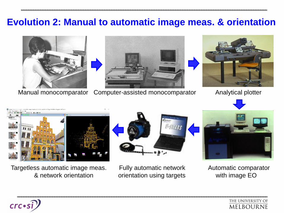
Evolution 2: Manual to automatic image meas. & orientation
Manual monocomparator Computer-assisted monocomparator Analytical plotter
Targetless automatic image meas. Fully automatic network Automatic comparator
& network orientation orientation using targets with image EO

Evolution 2: Manual to automatic image meas. & orientation
Manual monocomparator Computer-assisted monocomparator Analytical plotter
Targetless automatic image meas. Fully automatic network
& network orientation orientation using targets** Rollei Reseau-Scanning
automatic monocomparatror

Evolution 3: Manual Feature Extraction & Graphical Output to
Automatic 3D Point Cloud Generation
Further feature
extraction &
modelling, eg
within CAD
Textured dense point cloud or mesh 3D Point cloud, sparse or dense **
2D plan or map 3D feature points Targetted feature points

Operational Modes of CRP: On-Line & Off-Line
• On-line single or multi-camera, generally
for tracking or real-time measurement• Off-line, generally single camera
measurement of shape-invariant objects
**

Major CRP Developments in the Digital Era
• Coded targets/markers – facilitated auto-
orientation & 3D point determination, in both
off-line & on-line/real-time CRP systems
• FBM/SfM auto-orientation – facilitated auto-
orientation & sparse 3D point cloud generation
• Dense image matching – facilitated dense 3D
point cloud generation to pixel-level resolution
• Automatic camera calibration – facilitated by
coded targets or FBM orientation; has
enhanced accessibility to CRP **

Options for Orientation & 3D Object Reconstruction
Bundle Adjustment
(A)
Manual to Semi-Automated
Image Measurement
(B)
Automatic, using
coded targets
(C)
Automatic with no
targets (SfM approach)
Initial Network Relative Orientation
Bundle adjustment (+self-calibration) for Refined Network Relative/Exterior Orientation
(B)
Automatic 3D
coordinates for
targetted points
(C)
Automatic generation of
dense point cloud – no
targets
Subsequent Determination of 3D Points (generally with final Bundle Adjustment)
(A)
Manual or semi-
automated referencing or
measurement of targetted
or untargetted points

Direct versus Indirect
Feature Point Extraction
Direct
Direct
Indirect

Options for Orientation & 3D Object reconstruction
Bundle Adjustment
(A)
Manual to Semi-Automated
Image Measurement
(B)
Automatic, using
coded targets
(C)
Automatic with no
targets (SfM approach)
Initial Network Relative Orientation
Bundle adjustment (+self-calibration) for Refined Network Relative/Exterior Orientation
(B)
Automatic 3D
coordinates for
targetted points
(C)
Automatic generation of
dense point cloud – no
targets
Subsequent Determination of 3D Points (generally with final Bundle Adjustment)
(A)
Manual or semi-
automated referencing or
measurement of targetted
or untargetted pointsScenario: Auto-orientation followed
by manual feature point extraction

Manual Image Measurement
Note: Sfm is no panacea
• Applicable when there’s no targets, no texture and/or network
geometry not conducive to auto-orientation
• >2000 users of CRP in accident reconstruction in the US alone
(CRP has many attributes)
• On-line image measurement yields robust error detection &
blunder free solutions
• Conditions might be considered extreme, but they are the norm

Attributes of photogrammetry for accident reconstruction &
forensic measurement
• Fast scene recording minimal road closures & less traffic disruption
• Photography offers a permanent record; feature measurement at any time
• Technology is very low-cost; can use any camera
• Systems such as iWitness are very easy to use & provide fast & accurate
3D measurements
• Operational scenarios: manual through semi- to fully automatic
• Data redundancy affords robust and reliable quality measures

Photogrammetric measurement for accident reconstruction & forensics

Near-planar geometry not conducive to targetless orientation

Accident Reconstruction Undertaken by the Florida Highway Patrol

Project Example: Crash scene mapping of a tanker
explosion, Indianapolis at I-465 and I-69
Multi-level site was recorded in 3 networks
spanning 300m, in 70 minutes

Example Project: Scene mapping of tanker explosion

I-69 below I-465
Photogrammetric
Markers
Example Project: Scene mapping of tanker explosion

iWitness
Feature mapping for provision of evidence
Example Project: Scene mapping of tanker explosion

Automated CRP Using Targetting
Example: Door Frame & Door Hinges at AIRBUS Hamburg

Example: Dynamic control of a large milling
machine (trim & drill)
Real-time positioning control of a cutting tool: 1000s of holes (>20
different sizes), cut-outs (eg windows & doors ) and trimming
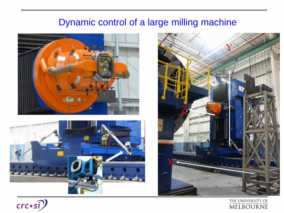
Dynamic control of a large milling machine
X
Y
Z

Measurement Example: Entire surface of Boeing 737

Measurement Example: Entire surface of Boeing 737

A 15 minute task for a 3D meas.
accuracy of 0.015mm; no
operator intervention beyond
loading the images **
Automatic measurement of wind turbine tower flanges

Automated stairway measurement for stairlift design & manufacture

Accuracy/performance evaluation for robot tracking **

Targetless, Automated Image Orientation
Holstentor, Luebeck: 43 image-network yielding 250,000 3D surface pts

Automated Object Reconstruction via Dense Matching
>10 million (visible) 3D points from dense image matching **
from SURE
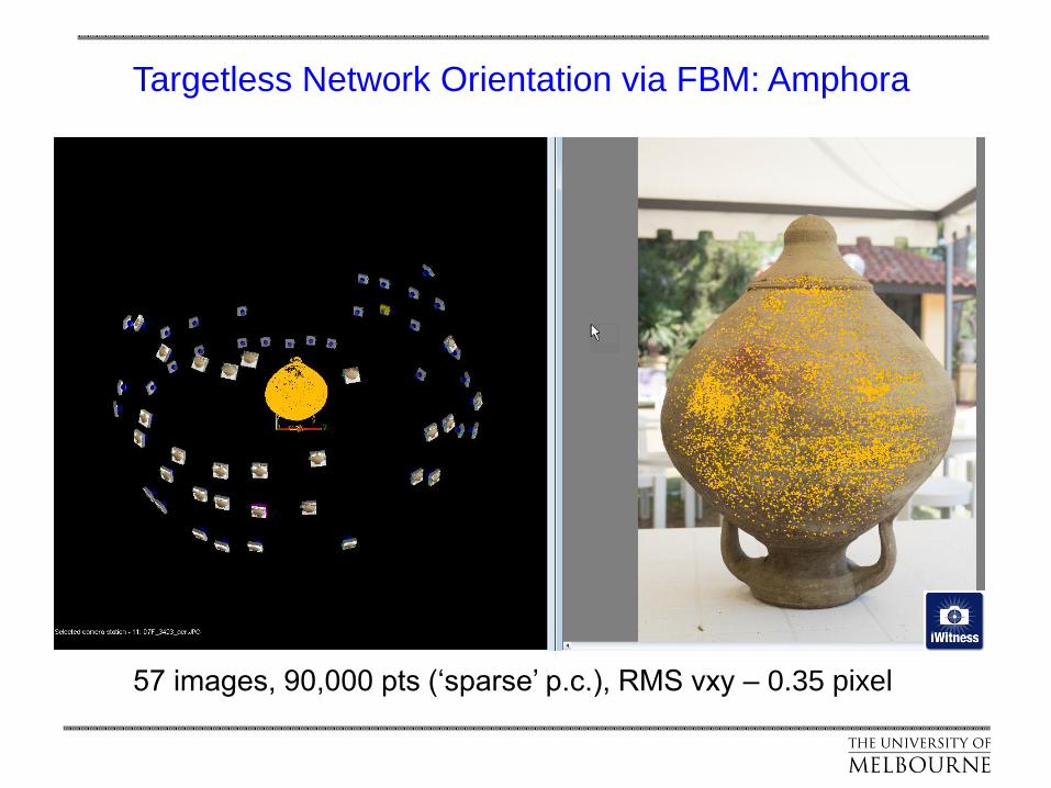
Targetless Network Orientation via FBM: Amphora
57 images, 90,000 pts (‘sparse’ p.c.), RMS vxy – 0.35 pixel

Targetless object reconstruction via dense matching: Amphora
Dense point cloud from SGM (via
SURE) comprising >20 million points
Triangulated mesh
from SURE

Examples taken from Photoscan Showcase (http://www.agisoft.com/community/showcase)
Targtless object reconstruction via SfM & dense matching

Important Practical Impact of Positional Information within SfM
Network Orientation
From Australis
• Without GPS camera
station positions, 297-
image network
orientation involves
43,956 pairwise image
matchings
• At 1 sec per pair,
requires 12 hours
• Knowledge of camera
station positions allows
pair selection to reduce
matches by 80-95%; ie
matching reduces to
<1.5 hours (2970 pairs
matched)
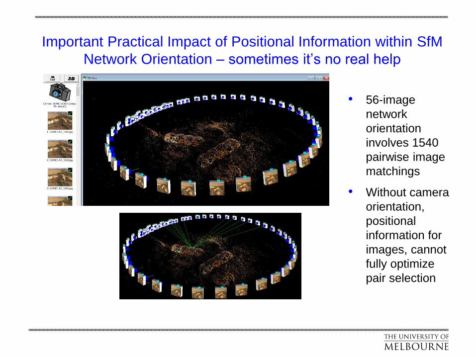
Important Practical Impact of Positional Information within SfM
Network Orientation – sometimes it’s no real help
• 56-image
network
orientation
involves 1540
pairwise image
matchings
• Without camera
orientation,
positional
information for
images, cannot
fully optimize
pair selection

What did photogrammetrists get out SfM developments?
• A powerful new approach to solving the image-point correspondence
problem, albeit to a precision that could be 10 times poorer than when
using targets (eg 0.3 pl versus 0.03 pl)
• Some new approaches to determination of initial values for non-linear
photogrammetric orientation models (eg bundle adjustment), but these
are not universally applicable
• Adoption of RANSAC-type approaches, eg for filtering of matches and
initial value determination; ie the notion of using solution plausibility
involving many point combinations rather than relying on high-quality
control/constraints comprising a few points.
• And … the headaches of processing & interacting with dense point
clouds (though not really a CV inspired issue!)

Block of 176 images, recorded from a DJI Inspire UAV. FBM auto-
orientation with subsequent dense matching to yield >1 million points
plus mesh
Traffic Accident Documentation & Reconstruction: Hybrid
auto & manual approach

Resulting dense point cloud
Traffic Accident Documentation & Reconstruction: Hybrid
auto & manual approach

Annotated point cloud, with features manually extracted from the
stereo imagery
Traffic Accident Documentation & Reconstruction: Hybrid
auto & manual approach

Traffic Accident Documentation & Reconstruction: Hybrid
auto & manual approach
Specific feature points added both photogrammetrically
(monoplotted or in stereo) & in CAD
Fix this image
UAV image inserted
to illustrate the option
of post-processed
3D points added to the
cloud from
iWitnessPRO-Agilis
Traffic Accident Reconstruction: Hybrid auto & manual approach

On-site image recording time of only 30 minutes
Traffic Accident Reconstruction: Hybrid auto & manual approach

Mapping by RCMP of fatal motorcycle accident from UAV
Sample image from UAV 3D point cloud from iWitnessPRO-Agilis
Ready for DXF export (CAD)Diagramming within point
cloud in CZPC software

FBM-based auto orientation can work OK … but beware!
Case 1: Bridge Deformation Survey
Summary of results suggests reasonable network orientation
8 images, >400 pts, RMS vxy=0.31pl, Accuracy 1:1,600

Target-based auto orientation:
Bridge Deformation Survey
Solution via targets with >5-ray intersections suggests something is wrong!
8 images, 52 pts, RMS vxy=3.2pl, Accuracy 1:800, all pts >5 rays

FBM-based auto orientation: Network orientation problem
One image has excessive outliers & another has a limited number of points

Target-based auto orientation: Problem diagnosis
Two images had the zoom setting changed from 18mm to 24mm
6 images, 52 pts, RMS vxy=0.18pl, Accuracy 1:7000, all pts >5 rays
Caution: Network diagnosis can be compromised via
black-box FBM auto-orientation
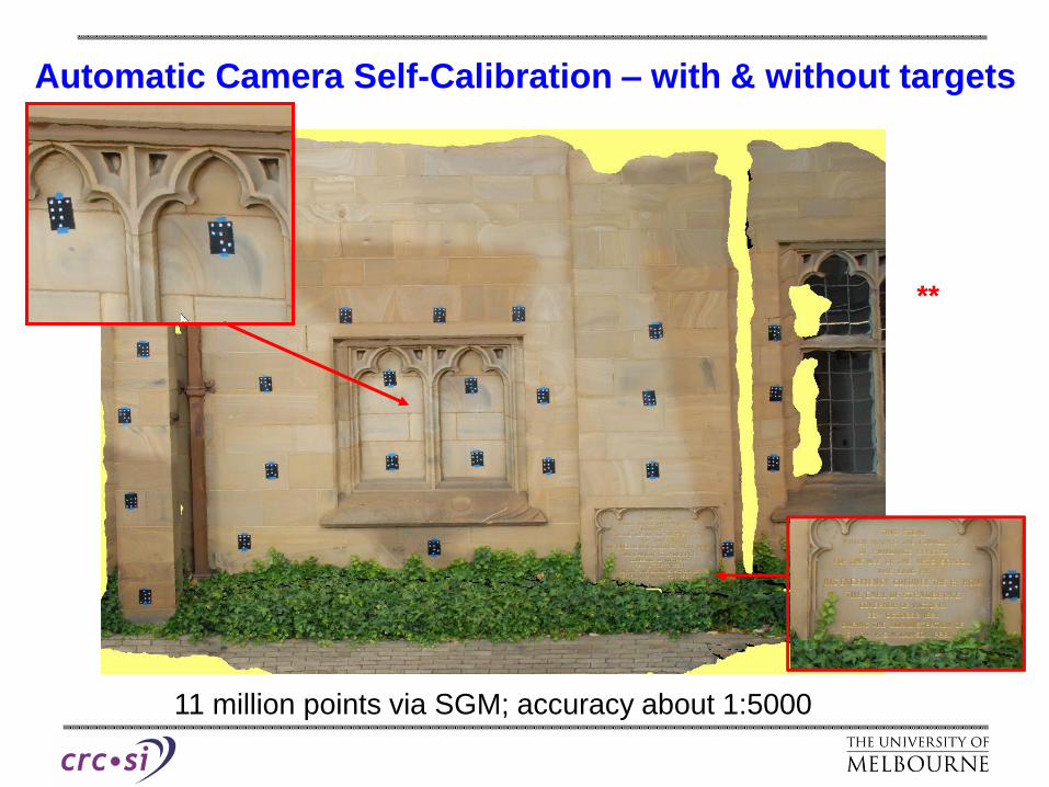
11 million points via SGM; accuracy about 1:5000
Automatic Camera Self-Calibration – with & without targets
**

Focal
length, c
(sc)
mm
xp
(sxp)
mm
yp
(sxp)
mm
Dr @
r=8mm
mm
Dr @
r=10mm
mm
Dr @
r=12.0mm
mm
P(r) @
r=10mm
mm
P(r) @
r=12mm
mm
RMS vxy
No of points
Coded
targets
17.632 (0.0010)
-0.038(0.0007)
-0.193 (0.0007) 121.8 217.2 332.2 5.7 8.1
0.09 pl
200
Untargeted17.627 (0.0008)
-0.036 (0.0005)
-0.193(0.0005) 120.9 216.2 333.1 5.3 7.6
0.25pl
55,500
Automatic Camera Calibration – with & without targets
27 images, 25,000 feature points, 200 target points (25 codes)
Results of self-calibrations of the Nikon D200 camera for targeted and untargeted cases.

FBM-based Auto Camera Calibration – a useful toolResults of self-calibrations of the Nikon D200 camera for untargeted case.
Feature-based matching
was successful at both
low incidence angle &
up to 900 convergence
angle
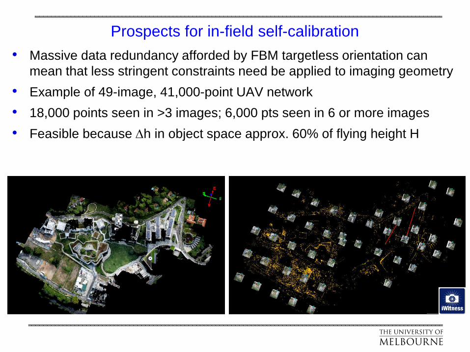
Prospects for in-field self-calibration
• Massive data redundancy afforded by FBM targetless orientation can
mean that less stringent constraints need be applied to imaging geometry
• Example of 49-image, 41,000-point UAV network
• 18,000 points seen in >3 images; 6,000 pts seen in 6 or more images
• Feasible because Dh in object space approx. 60% of flying height H

Prospects for ‘natural’ object point fields for self-calibration
• PhaseOne camera with 50mm lens
• 40-images, 3300 points (all with 6 or more rays), RMS vxy = 0.20 pixel
• Convergence could be relaxed because Dh in object space >50% of H
• Standard errors of 2 mm for c & <1 mm for xp,yp

Future Prospects: Challenging Areas of Research for ISPRS
Very relevant to CRP
From Australis

Future Prospects: Active Research Areas for Information from Imagery
Very relevant to CRP **
From Australis

Future Prospects: Example ‘Hot Topics’ in CRP R&D **
Sensing: PMD/ToF 3D cameras,
structured light, PTZ, MEMS for
image orientation, R-T object
recognition & ID, FMV, non-central
projection cameras (line, fisheye,
plenoptic/light field, mirror)
Modelling: hybrid orientation,
temporal modelling, R-T processing
of image sequences, 3D data fusion,
multi-modal integration, CAD driven
orientation/modelling
Miscellaneous: Human machine interfaces, scripting, metric use of
thematic inform., data quality & standards, point cloud processing

Options for Orientation & 3D Object reconstruction
Bundle Adjustment
(A)
Manual to Semi-Automated
Image Measurement
(B)
Automatic, using
coded targets
(C)
Automatic with no
targets (SfM approach)
Initial Network Relative Orientation
Bundle adjustment (+self-calibration) for Refined Network Relative/Exterior Orientation
(B)
Automatic 3D
coordinates for
targetted points
(C)
Automatic generation of
dense point cloud – no
targets
(SfM or FBM approach)
Subsequent Determination of 3D Points (generally with final Bundle Adjustment)
(A)
Manual or semi-
automated referencing or
measurement of targetted
or untargetted points
Real Question: What is actually
needed from the
photogrammetric survey?

There’s an old saying in English that:
“xxx wrote the book on yyyy”
Implying that xxx is the font of all knowledge on the subject
(well … almost!)
Final Remark

THANK YOU & HAPPY BIRTHDAY iapg
Within the context of Close-Range Photogrammetry, this
saying could well be presented as:
“Thomas Luhmann, with his some 30 years professional
experience and 20 years of successful leadership at iapg,
with the backing from his work colleagues, has literally written
the book on close-range photogrammetry … through multiple
editions in fact.”
Final Remark