evolution series 8' poke-thru devices installation
TRANSCRIPT
1
Wiremold electrical systems conform to and should be properlygrounded in compliance with requirements of the current NationalElectrical Code or codes administered by local authorities.
All electrical products may present a possible shock or fire hazard if improperly installed or used. Wiremold electrical products may bear the mark as UL Listed and/or Classified and should be installed in conformance with current local and/or the NationalElectrical Code.
Products Covered: 8ATCP, 8ATP, 8ATC, 8AT, 8STC, 8CTC, 8CT, 68REC, 68MAAP, 682A, 68B, 8DP, 8DEC, 8S1, 8S2,8MAAP, 8AAP, 8B, 8TS, 8STCP, 575CHA, 575PTHA, 575BLH, 175CHA, 1125CHA, 1PTHA, 1BLH, 22CHA, CE8STCP
CAUTION:DO NOT operate tile stripper, cleaning, or resurfacing equipment over top of covers. This may result in damage to the surface finish of the product.
Suitable for use in air handling spaces in accordance with Sec. 300-22 (C) of the National Electrical Code.
Evolution™ Series8" Poke-Thru DevicesI N S T A L L A T I O N I N S T R U C T I O N SInstallation Instruction No.: 1 007 156 R2 – Updated May 2010
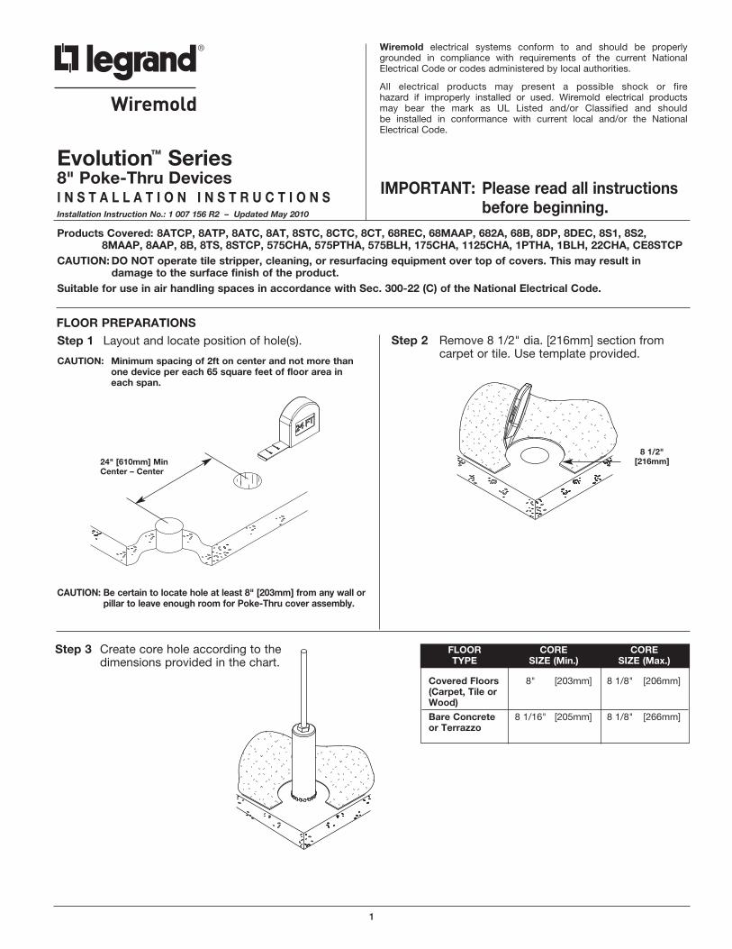
CAUTION: Be certain to locate hole at least 8" [203mm] from any wall orpillar to leave enough room for Poke-Thru cover assembly.
IMPORTANT: Please read all instructionsbefore beginning.
CAUTION: Minimum spacing of 2ft on center and not more thanone device per each 65 square feet of floor area in each span.
Step 2 Remove 8 1/2" dia. [216mm] section fromcarpet or tile. Use template provided.
Step 1 Layout and locate position of hole(s).
FLOOR PREPARATIONS
24" [610mm] MinCenter – Center
8 1/2" [216mm]
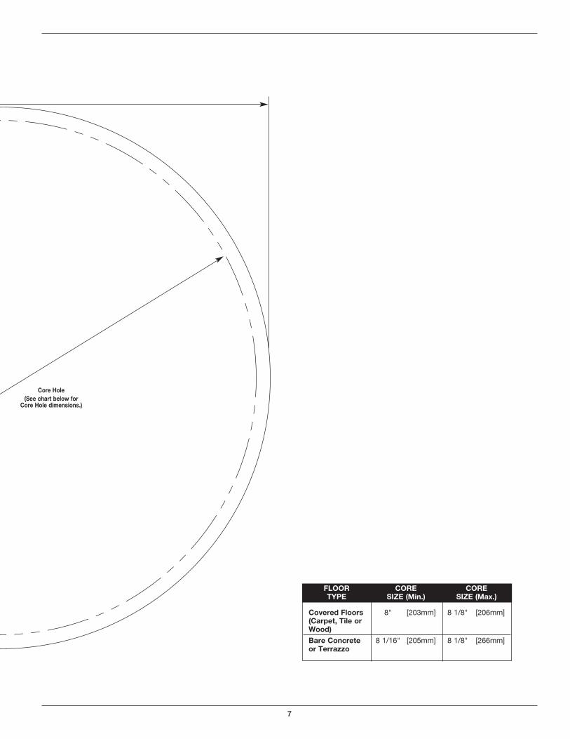
Covered Floors 8" [203mm] 8 1/8" [206mm](Carpet, Tile orWood)
Bare Concrete 8 1/16" [205mm] 8 1/8" [266mm]or Terrazzo
FLOOR CORE CORETYPE SIZE (Min.) SIZE (Max.)
Step 3 Create core hole according to thedimensions provided in the chart.
2
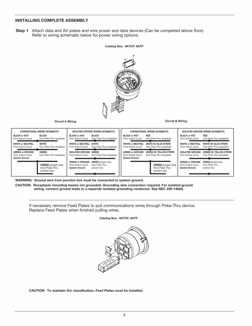
CONVENTIONAL WIRING SCHEMATIC ISOLATED GROUND WIRING SCHEMATIC
BLACK or HOT BLACK BLACK or HOT BLACKFrom branch circuit from Poke-Thru receptacle From branch circuit from Poke-Thru receptacle
WHITE or NEUTRAL WHITE WHITE or NEUTRAL WHITEFrom branch circuit from Poke-Thru receptacle From branch circuit from Poke-Thru receptacle
GREEN or GROUND GREEN ISOLATED GROUND GREENFrom branch circuit from Poke-Thru receptacle From branch circuit from Poke-Thru receptacleSystem Ground
GREEN or GROUND GREEN (jumper wire)From branch circuit from Poke-ThruSystem Ground junction box
Step 1 Attach data and AV plates and wire power and data devices (Can be completed above floor). Refer to wiring schematic below for power wiring options.
INSTALLING COMPLETE ASSEMBLY
Catalog Nos. 8ATCP, 8ATP
WARNING: Ground wire from junction box must be connected to system ground.
CAUTION: Receptacle mounting means not grounded. Grounding wire connection required. For isolated groundwiring, connect ground leads to a separate isolated grounding conductor. See NEC 250-146(d).
If necessary remove Feed Plates to pull communications wires through Poke-Thru device. Replace Feed Plates when finished pulling wires.
Catalog Nos. 8ATCP, 8ATP
CAUTION: To maintain fire classification, Feed Plates must be installed.
GREEN (jumper wire) from Poke-Thru junction box
Circuit A Wiring Circuit B Wiring
CONVENTIONAL WIRING SCHEMATIC ISOLATED GROUND WIRING SCHEMATIC
BLACK or HOT RED BLACK or HOT REDFrom branch circuit from Poke-Thru receptacle From branch circuit from Poke-Thru receptacle
WHITE or NEUTRAL WHITE W/ BLUE STRIPE WHITE or NEUTRAL WHITE W/ BLUE STRIPEFrom branch circuit from Poke-Thru receptacle From branch circuit from Poke-Thru receptacle
GREEN or GROUND GREEN W/ YELLOW STRIPE ISOLATED GROUND GREEN W/ YELLOW STRIPEFrom branch circuit from Poke-Thru receptacle From branch circuit from Poke-Thru receptacleSystem Ground
GREEN or GROUND GREEN (jumper wire)From branch circuit from Poke-ThruSystem Ground junction box
GREEN (jumper wire) from Poke-Thru junction box
3
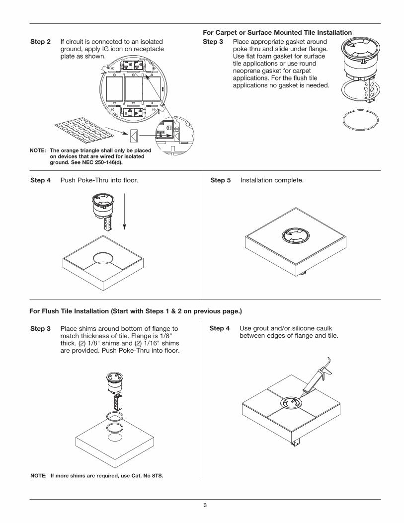
Step 4 Push Poke-Thru into floor.
Step 3 Place appropriate gasket aroundpoke thru and slide under flange.Use flat foam gasket for surfacetile applications or use roundneoprene gasket for carpetapplications. For the flush tileapplications no gasket is needed.
Step 2 If circuit is connected to an isolatedground, apply IG icon on receptacleplate as shown.
Step 5 Installation complete.
For Carpet or Surface Mounted Tile Installation
For Flush Tile Installation (Start with Steps 1 & 2 on previous page.)
Step 3 Place shims around bottom of flange tomatch thickness of tile. Flange is 1/8"thick. (2) 1/8" shims and (2) 1/16" shimsare provided. Push Poke-Thru into floor.
Step 4 Use grout and/or silicone caulkbetween edges of flange and tile.
NOTE: If more shims are required, use Cat. No 8TS.
NOTE: The orange triangle shall only be placedon devices that are wired for isolatedground. See NEC 250-146(d).
4
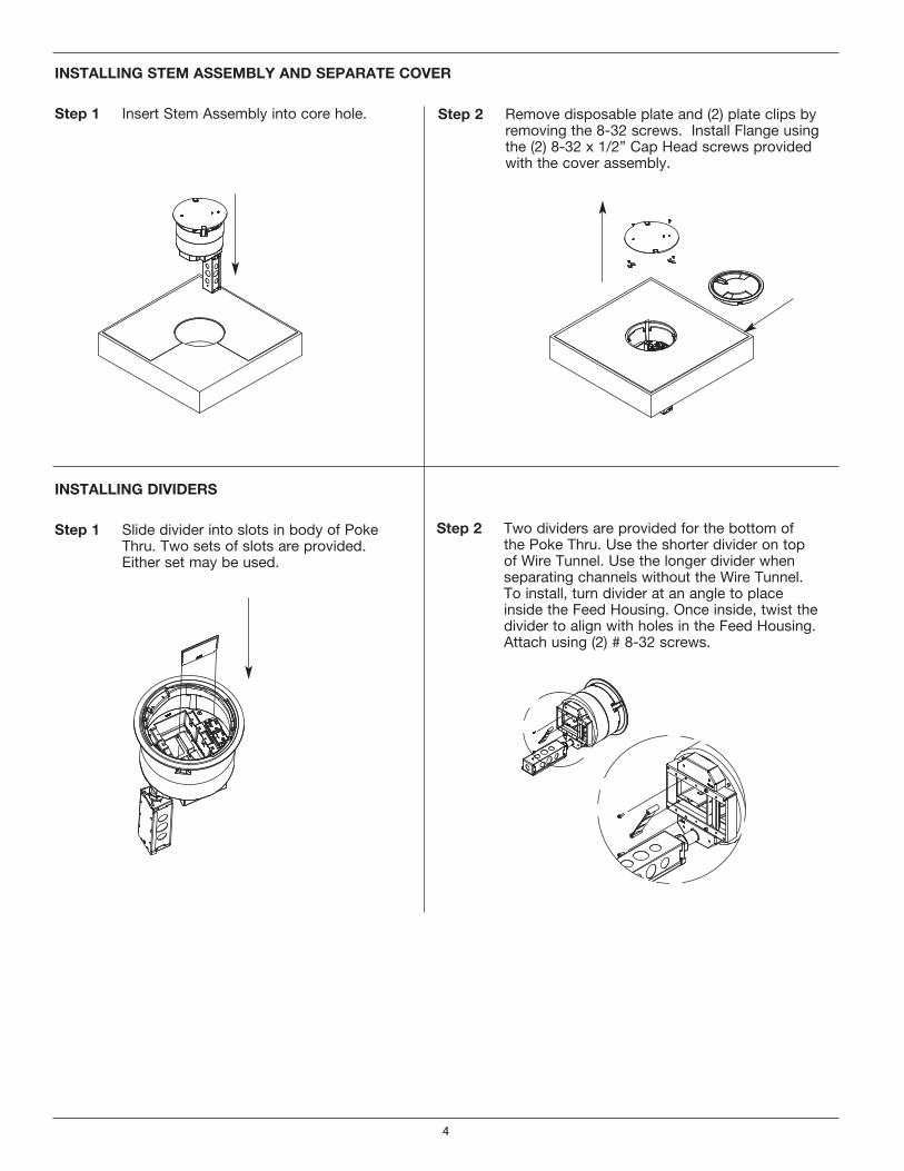
Step 1 Insert Stem Assembly into core hole.
INSTALLING STEM ASSEMBLY AND SEPARATE COVER
Step 2 Remove disposable plate and (2) plate clips byremoving the 8-32 screws. Install Flange usingthe (2) 8-32 x 1/2” Cap Head screws provided with the cover assembly.
Step 1 Slide divider into slots in body of Poke Thru. Two sets of slots are provided. Either set may be used.
INSTALLING DIVIDERS
Step 2 Two dividers are provided for the bottom ofthe Poke Thru. Use the shorter divider on topof Wire Tunnel. Use the longer divider whenseparating channels without the Wire Tunnel.To install, turn divider at an angle to placeinside the Feed Housing. Once inside, twist thedivider to align with holes in the Feed Housing.Attach using (2) # 8-32 screws.
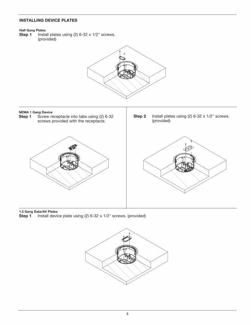
5
Half Gang PlatesStep 1 Install plates using (2) 6-32 x 1/2" screws.
(provided)
INSTALLING DEVICE PLATES
NEMA 1 Gang DeviceStep 1 Screw receptacle into tabs using (2) 6-32
screws provided with the receptacle.Step 2 Install plates using (2) 6-32 x 1/2" screws.
(provided)
1.5 Gang Data/AV PlatesStep 1 Install device plate using (2) 6-32 x 1/2" screws. (provided)

6
Carpet Cutout8 1/2" [216mm]
Carpet Cutout Template
CAUTION: When printing copies of thistemplate please be sure templateis scaled correctly and is the correct size once it is printed.
7
Covered Floors 8" [203mm] 8 1/8" [206mm](Carpet, Tile orWood)
Bare Concrete 8 1/16" [205mm] 8 1/8" [266mm]or Terrazzo
FLOOR CORE CORETYPE SIZE (Min.) SIZE (Max.)
Core Hole (See chart below for
Core Hole dimensions.)
8
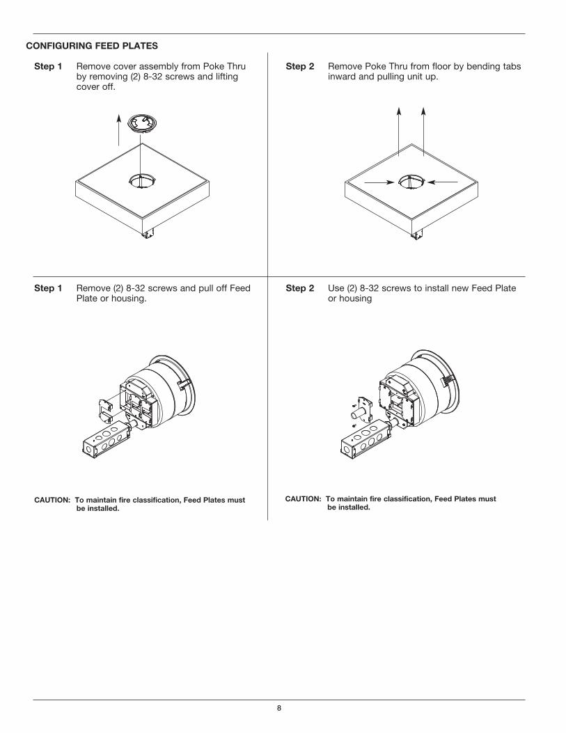
Step 1 Remove (2) 8-32 screws and pull off Feed Plate or housing.
Step 2 Use (2) 8-32 screws to install new Feed Plate or housing
CAUTION: To maintain fire classification, Feed Plates mustbe installed.
CAUTION: To maintain fire classification, Feed Plates mustbe installed.
Step 1 Remove cover assembly from Poke Thru by removing (2) 8-32 screws and lifting cover off.
CONFIGURING FEED PLATES
Step 2 Remove Poke Thru from floor by bending tabs inward and pulling unit up.
9
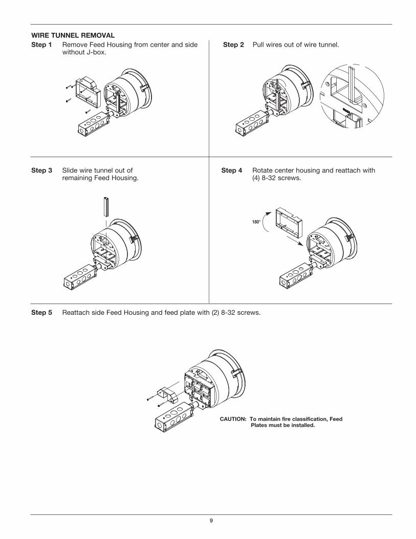
Step 5 Reattach side Feed Housing and feed plate with (2) 8-32 screws.
CAUTION: To maintain fire classification, FeedPlates must be installed.
Step 3 Slide wire tunnel out ofremaining Feed Housing.
Step 4 Rotate center housing and reattach with (4) 8-32 screws.
WIRE TUNNEL REMOVALStep 1 Remove Feed Housing from center and side
without J-box.Step 2 Pull wires out of wire tunnel.
180°
10
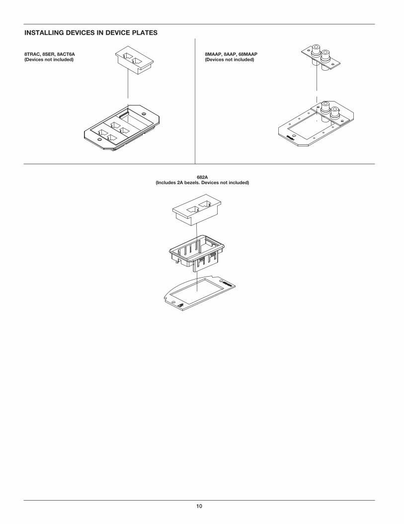
INSTALLING DEVICES IN DEVICE PLATES
8TRAC, 8SER, 8ACT6A (Devices not included)
8MAAP, 8AAP, 68MAAP(Devices not included)
682A (Includes 2A bezels. Devices not included)
11
Evolution Series Poke-Thru Devices are UL Listed and Classified to U.S. and Canadian safety standards to the following conditions:
The 8STC Poke-Thru Stem with the 8CTC or 8CT Service Head Fitting, and the 8ATCP, 8ATP, 8ATC or 8AT factory assembledPoke-Thru devices are for use with 1-, 1 1/2-, or 2- hour rated unprotected reinforced concrete floors and 1-, 1 1/2-, or 2- hour rated floors employing unprotected steel floor units and concrete topping (D900 Series Designs), or concrete floors with suspendedceilings. (Fire resistive designs with suspended ceilings should have provisions for accessibility in the ceiling area below the Poke-Thru fittings).
The assembled Poke-Thru stem and service fitting will not reduce the ratings of the floor assembly when the thickness and type of concrete (required for the specific rating) are within the specified limits and the fittings are installed as specified:
1. Spacing – Minimum of 2' [610mm] OC and not more than one unit per 65 sq. ft. [6 m2] of floor area in each span.
2. Concrete – Minimum thickness of structural concrete topping of 2 1/4" [57mm] over metal deck or a minimum 3" [76mm] thick reinforced concrete slab. Unit weight of concrete to be 110 to 155 pcf.
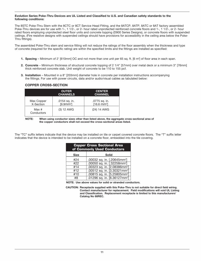
3. Installation – Mounted in a 8" [203mm] diameter hole in concrete per installation instructions accompanying the fittings. For use with power circuits, data and/or audio/visual cables as tabulated below:
The “TC” suffix letters indicate that the device may be installed on tile or carpet covered concrete floors. The “T” suffix letterindicates that the device is intended to be installed on a concrete floor, embedded into the tile covering.
Size Solid
#24 .00032 sq. in. [.20645mm2] #22 .00050 sq. in. [.32258mm2] #14 .00323 sq. in. [2.08386mm2] #12 .00512 sq. in. [3.30321mm2] #10 .00815 sq. in. [5.25805mm2] #8 .01296 sq. in. [8.36127mm2]
Copper Cross Sectional Area of Commonly Used Conductors
NOTE: Use above values for solid or stranded conductors.
Max Copper .0154 sq. in. .0775 sq. in.X-Section [9.9mm2] [16.6 mm2]
Max # (3) 12 AWG (24) 14 AWGConductors
OUTER CENTERCHANNELS CHANNEL
COPPER CROSS-SECTION
NOTE: When using conductor sizes other than listed above, the aggregate cross-sectional area ofthe copper conductors shall not exceed the cross-sectional areas listed.
CAUTION: Receptacle supplied with this Poke-Thru is not suitable for direct field wiring.Contact manufacturer for replacement. Field modifications will void UL Listingand Classification. Replacement receptacle is limited to this manufacturers'Catalog No 68REC.

WiremoldU.S. and International: 60 Woodlawn Street • West Hartford, CT 061101-800-621-0049 • FAX 860-232-2062 • Outside U.S.: 860-233-6251 Canada:570 Applewood Crescent • Vaughan, Ontario L4K 4B41-800-723-5175 • FAX 905-738-9721
1 007 156 R2 0510© Copyright 2010 Legrand/Wiremold All Rights Reserved