evo.sys manual rs - jbl · pdf fileevo wireless receiver system controller 24. for
TRANSCRIPT

A Loudspeaker System With Intelligence
EVOi.sys
User’s Guide
Introducing The Next Generation of Installed Sound

C O N T E N T SEVOi.sysSafety Information . . . . . . . . . . . . . . . . . . . . . . . . . . 2
Introduction . . . . . . . . . . . . . . . . . . . . . . . . . . . . . . . 3
Design Overview . . . . . . . . . . . . . . . . . . . . . . . . . . . . 4
Hook-Up/Setup. . . . . . . . . . . . . . . . . . . . . . . . . . . . . . 5
Mixer Operation . . . . . . . . . . . . . . . . . . . . . . . . . . . 10
Input Channel . . . . . . . . . . . . . . . . . . . . . . . . . . . . . 10Master Section . . . . . . . . . . . . . . . . . . . . . . . . . . . . 14
Microphone Operation . . . . . . . . . . . . . . . . . . . . . . 18
EVO Handheld Dynamic Microphone . . . . . . . . . . . 18EVO Wireless Handheld Dynamic Microphone . . . . 21EVO Lavaliere Microphone/Bodypack Transmitter . 22EVO Wireless Receiver System Controller. . . . . . . . 24
Applications . . . . . . . . . . . . . . . . . . . . . . . . . . . . . . 26
Troubleshooting . . . . . . . . . . . . . . . . . . . . . . . . . . . 28
Technical Data . . . . . . . . . . . . . . . . . . . . . . . . . . . . . 29
Warranty . . . . . . . . . . . . . . . . . . . . . . . . . . . . . . . . . 32©2001 JBL Professional Products

2
S A F E T Y
IMPORTANT SAFETY INFORMATION
This equipment has been tested and found to comply with the following European and international standards forElectromagnetic Compatibility and Electrical Safety:
Radiated Emmissions (EU): EN55022B (1992)RF Immunity (EU): IEC801-3 (1994)Electrostatic Discharge(EU): IEC801-2 (1984)Fast Transients(EU): IEC801-4 (1988)Electrical Safety (EU): EN60065 (1994)Electrical Safety(USA): UL6500/ETL (1996)Electrical Safety(CAN): CAN/CSA-E65/ETLc (1996)
Before using the apparatus read these instructions, follow all instructions, heed them and keep in a safe place.
Clean only with a damp cloth. Do not block any of the ventilation openings. Install in accordance with the manufacturer’s instructions.
Do not defeat the safety purpose of the grounding type plug. A grounding plug has two blades and a third grounding prong. Thethird prong is provided for your safety. When the provided plug does not fit into your outlet, consult an electrician for replacementof the obsolete outlet.
Protect the power cord from being walked on or pinched particularly at plugs, convenience recepticals and the point where theyexit from the apparatus.
Only use attachments/accessories specified by the manufacturer.
Unplug this apparatus during lightning storms or when not in use for a long time.
WARNING - TO REDUCE THE RISK OF FIRE OR SHOCK, DO NOT EXPOSE THIS APPARATUS TO RAIN OR MOISTURE.
DO NOT REMOVE COVERS, NO USER SERVICABLE PARTS INSIDE, REFER SERVICING TO QUALIFIED SERVICE PERSONNEL.
THIS EQUIPMENT MUST BE GROUNDED.
IT SHOULD NOT BE NECESSARY TO REMOVE ANY PROTECTIVE GROUND OR SIGNAL CABLE SHIELD CONNECTIONS TO PREVENT GROUND LOOPS. ANY SUCH DISCONNECTIONS ARE OUTSIDE THE RECOMMENDED PRACTICE OF JBL PROFESSIONAL AND WILL RENDER ANY EMC OR SAFETYCERTIFICATION VOID.
For continued compliance with international EMC legislation ensure that all input and output cables are wired with the cablescreen connected to Pin 1 of the XLR connectors. The input XLR Pin 1 is connected to the chassis via a low value capacitor, providing high immunity from ground loops while ensuring good EMC performance.
3
I N T R O D U C T I O N
WELCOMEWelcome to EVO Intelligent Sound Reinforcement Systems.
Thank you for trusting JBL with your sound. It’s an honor wedon’t regard lightly. As a world leader in sound reinforcement,JBL sound systems are permanently installed in many famousarenas, concert halls, theaters, theme parks and clubs. In fact,JBL speakers provide the body, substance and clarity fortoday’s hottest music acts, showcase stores and premiererestaurants you just can’t make a more professional choice.
JBL Professional products are the result of over 50 years ofdesign and manufacture of sound reinforcement solutions.From cathedrals to discos, to arenas and small boutiques, JBLhas successfully provided the tools and system resources tomeet and exceed every need. It’s with this experience and suc-cess that JBL offers EVO, the first fully designed sound rein-forcement system with built-in intelligence. Congratulationson your purchase.
USING THIS GUIDEThe majority of content in this Guide is instruction on theday to day operation of EVOi.sys. EVOi.324 and EVOi.netare both components of EVOi.sys. It is necessary to retain the
Guides found in the EVOi.324 packaging. Operation of theEVOi.net is contained in the EVOi.net Users Guide. A thorough understanding of these Guides is necessary for correct installation and set-up of EVOi.sys.
As you follow the EVOi.sys Users Guide each reference toeither EVOi.324 or EVOi.net Guide is identified with thecolor associated with the product:EVOi.sys - BlueEVOi.324 - YellowEVOi.net - Green
PACKAGING CONTENTS2 x EVOi.324 Contents:
EVOi.324 Speaker SystemAccessory bag which includes:
1 AC Power Cord, 1 Eyebolt Kit, Two Small Rubber Feet, 1 Large Rubber Foot, 1 Large Washer
EVOi.324 Users GuideTech Note #14 Vol.1
EVOi.sys Mixer Station Contents:EVO Mixer StationAC Power CordUHF Handheld Transmitter with Dynamic Microphone Head with ClipUHF Body Pack Transmitter with Condenser Lavalier Microphone with Tie ClipSix Handheld Dynamic Microphones with Clips
EVOi.sys Accessories Contents:JBL Measurement Microphone with ClipFour Boom Microphone StandsSix 50 ft XLR CablesFour 2 ft XLR CablesThree 100 ft XLR CablesMixer Station Dust CoverEVOi.sys, EVOi.net Users Guides

4
E V O I . S Y S
THANK YOUThank you for purchasing an EVOi.sys the first FullyDesigned Sound Reinforcement System. You have just takendelivery of the World’s most comprehensive designed soundreinforcement system. Everything is supplied to get a profes-sional sound reinforcement system up and running in theshortest possible time with the minimum of stress and themost reliability. For maximum satisfaction and optimumresults please read this guide thoroughly. You will be requiredto understand the placement of EVOi.324 loudspeakers and the operation of EVOi.net and will be directed to the relevantsections in this guide. However, through the intricate digitaldesign and integration of sound system technology a largeportion of tedious system installation and configuration hasbeen eliminated.
DESIGN OVERVIEWEVOi.sys has been specifically designed to provide all the elements of a sound reinforcement system in one simple toorder, quick to install, easy to set-up and straight forward tooperate package. The professional nature, performance andquantity of equipment supplied has been finely tailored to suit sound reinforcement applications in performing arts, worship space, educational and civic venues of up to five hundred seat capacity. For larger venues, provision has beenmade such that additional EVO loudspeakers can be added tothe system. For complex productions additional wired andwireless microphone can be easily added.
FCC STATEMENTThis equipment has been tested and found to comply with the limits for a Class B digital device, pursuant to Parts 74, 15, and90 of the FCC Rules. These limits are designated to provide reasonable protection against harmful interference in a residentialinstallation. This equipment generates, uses and can radiate radio frequency energy and, if not installed and used in accordancewith the instructions, may cause harmful interference to radio communications. However, there is no guarantee that interferencewill not occur in a particular installation. If this equipment does cause harmful interference to radio or television reception,which can be determined by turning the equipment off and on, the user is encouraged to try to correct the interference by one or more of the following measures:
• Reorient or relocate the receiving antenna.• Increase the separation between the equipment and the receiver.• Connect the equipment to an outlet on a circuit different from that to which the receiver is connected.• Consult the dealer or an experienced radio/TV technician for help.
Shielded cables and I/O cards must be used for this equipment to comply with the relevant FCC regulations. Changes or modifications not expressly approved in writing by AKG may void the user's authority to operate this equipment.
This device complies with Part 15 of the FCC Rules. Operation is subject to the following two conditions: (1) this device maynot cause harmful interference and (2) this device must accept any interference received, including interference that may causeundesired operation.

CONNECTING THE POWER
5
H O O K - U P / S E T U P
BALANCED UNBALANCED
BALANCEDLINE MIC
POWERAC/DC 12-16 V
20 mASet: XXXX
SNR: XXXXX
For IM-free frequenciesrefer to manual
BALANCED UNBALANCED
BALANCEDLINE MIC
POWERAC/DC 12-16 V
20 mASet: XXXX
SNR: XXXXX
For IM-free frequenciesrefer to manual
EVOi.sys Rear(NOTE: For clarity, the Power Supply is shown outside the frame.)
Power Supply(shown outside of frame)
NOTE: Power Cables AreAttached Behind ThePower Supply.
IMPORTANT: Make sure POWER is offbefore making connections.
To AC OutletPower Cord (supplied)

CONNECTING THE NETWORK
6
H O O K - U P / S E T U P
BALANCED UNBALANCED
BALANCEDLINE MIC
POWERAC/DC 12-16 V
20 mASet: XXXX
SNR: XXXXX
For IM-free frequenciesrefer to manual
BALANCED UNBALANCED
BALANCEDLINE MIC
POWERAC/DC 12-16 V
20 mASet: XXXX
SNR: XXXXX
For IM-free frequenciesrefer to manual
EVOi.sys Rear(NOTE: For clarity, power connections are not shown – see previous page.)
EVOi.324Input
EVO Measurement Microphone Output
EVOi.324Input
EVOi.324R Rear
EVOi.324L Rear
R L
R L
2' XLR Signal Cables(supplied)
100' XLR Signal Cables (supplied)
100' XLR Signal Cable(supplied)
R L
IMPORTANT: Make sure POWER is offbefore making connections.

CONNECTING THE MICROPHONES
7
H O O K - U P / S E T U P
BALANCED UNBALANCED
BALANCEDLINE MIC
POWERAC/DC 12-16 V
20 mASet: XXXX
SNR: XXXXX
For IM-free frequenciesrefer to manual
BALANCED UNBALANCED
BALANCEDLINE MIC
POWERAC/DC 12-16 V
20 mASet: XXXX
SNR: XXXXX
For IM-free frequenciesrefer to manual
EVOi.sys Rear(NOTE: For clarity, power and network connections are not shown – see previous pages.)
1 Mic
2' XLR Signal Cables (supplied)
50' XLR Signal Cables(supplied)
Mic2
IMPORTANT: Make sure POWER is offbefore making connections.
EVO Dynamic Microphones (supplied)

SETTING UP THE WIRELESS MICROPHONES
8
H O O K - U P / S E T U P
GAIN CHANNEL
RF OFF
1.5
V
IEC
LR
6
CHANNEL
GAIN
PWR
1
0
MIC
1
0
01
23456
7
89
A
B C D E
F
EVOi.sys Partial Front
EVO Lavaliere Microphone(supplied)
EVO BodypackTransmitter
(supplied)
EVO HandheldMicrophone
(supplied)
Set ToCH 3
IMPORTANT: Make sure POWER (on the Power Supply rear) is offbefore setting up microphones.
Set ToCH 1
AA
AA
AA AA
SETTING UP THE SYSTEM
Initial SettingsBefore powering on the system, set the following controls totheir initial settings:
• On the EVOi.sys Power Supply: POWER = OFF
• On the EVOi.sys Mixer:All Faders = ∞ “all the way down”All Pan, Send, and Return controls = 0All MUTE buttons = On
All microphone SENS controls = – 30
MIC 48V (POWER) = OFF
• On the EVOi.sys Receivers, One and Two:POWER = Off
Power On1. Verify that the voltage setting and fuse value on the
EVOi.sys (rear) is set for your ac power service (e.g., 115 V).
2. Connect AC MAINS on all EVOi.324s (see page 6EVOi.sys Users Guide) to active ac outlets. Each powerindicator will turn on.
3. On the EVOi.sys (rear), press POWER to the ON position.The POWER indicator (on the EVOi.net) will turn on.
Testing The SystemPerform the instructions listed in the EVOi.net section,Installation/Setup – Starting Up starting on page 7 EVOi.netUsers Guide.
Setting Up The Initial Mixl. Connect other sources (e.g, phantom-powered micro-
phone, keyboard, etc.) to available inputs and release theMUTE switches on all channels being used. If required,press MIC 48V to On to supply phantom power. ThePOWER LED will turn on.
2. Set the L MIX R and L SUB R faders to 0. On all inputchannels with signal, press MIX to route the signal to themix buss.
3. On the Master section, select MIX as the monitor sourceand select PFL as the listening mode.
4. Press SOLO on Channel 1 while a performer provides atypical performance-level signal. Observe the level on thebargraph meters and adjust SENS until the meter displayis in the amber section, with occasional peaks to the firstred LED for a typical maximum source level. This settingwill allow sufficient headroom to accommodate peaks andestablishes the maximum level for normal operation.
NOTE: The SENS setting is only the starting point for your mix.
Remember that many factors affect the sound during a live perfor-
mance, including EQ settings or even audience size.
5. Release SOLO on Channel 1. Repeat steps 4 and 5 for allother channels as required.
You are now ready to start building the mix and this shouldbe done progressively, listening carefully for each componentin the mix and watching the meters for any hint of overload.If this occurs, back off the appropriate Channel fader slightlyuntil the level being monitored is out of the red segments, oradjust the faders. This procedure will ensure that the mixer isset up correctly, with adequate headroom.
Operating The EquipmentTo learn more about EVOi.sys, we encourage you to study theremaining pages in this section to learn how to operate thecontrols on the mixer and microphone equipment. If youencounter any problems, please refer to Troubleshooting at theend of this manual.
Power OffImportant
Before turning off, make sure L Mix R faders are set to ∞ “allthe way down”.
9
H O O K - U P / S E T U P

INPUT CHANNEL
MIC InputThe MIC input accepts a male XLR connector and is designedto suit a wide range of balanced or unbalanced signals. Use pro-fessional dynamic, condenser, or ribbon microphones, becausetheir low impedance helps to reduce background noise com-pared to low-cost high-impedance microphones. If you pressdown the MIC 48 V switch (see master section detail) the XLRreceptacle provides a suitable power voltage for professionalcondenser microphones (a.k.a., Phantom Power). When using aMIC input, unplug any signal from the LINE input and adjustthe input level using the SENS control.
IMPORTANT: To prevent damage to the mixer or external
devices, only connect condenser microphones when MIC
48 V is off (i.e., switch up), and only turn it off or on with
all output faders down. When using unbalanced micro-
phones, make sure MIC 48 V is off, since phantom power
supplied on pins 2 and 3 of the XLR connector may damage
the equipment.
LINE InputEach LINE input accepts a 3-pole A-gauge (TRS) plug. Use thishigh impedance input for sources other than microphones,such as keyboards, drum machines, synthesizers, tapemachines, or guitars. The LINE input is balanced for low noiseand top-quality signal transfer from professional equipment.To use unbalanced sources, wire the plugs as shown and keepcable lengths as short as possible. When using a LINE input,unplug any microphone from the MIC input and adjust theinput level using the SENS control.
SENS (Sensitivity)This control sets how much of the source signal is sent to therest of the mixer. Too high, and the signal will distort as itoverloads the channel. Too low, and the level of any back-ground hiss will be more noticeable, and you may not be ableto get enough signal level to the output of the mixer.
3
2
1
10
M I X E R O P E R A T I O N
Phantom Power(Master Section)
Wiring XLRs
Unbalanced Input
Balanced Input
Wiring Plugs
Unbalanced Input
Balanced Input
Insert
3
15
14
2
1
7
8
10
11
12
13
5
6
4
9
INPUTCHANNEL
INPUTS(Rear Panel)
Setting the SENS control to 10 gives approximate unity gainfor the LINE input. Some sound equipment, including homeconsumer products, may operate at a lower level (i.e., -10 dBv)than professional equipment and, therefore, will require settingSENS to a higher gain to reach the same output level.
See Setting Up the System on page 9 to learn how to set SENS
correctly.
100 Hz Hi-Pass FilterPressing this switch activates a steep 18 dB per octave filterwhich reduces the level of bass frequencies only. Use this filterin live PA (public address) situations to clean up the mix,reducing stage rumble or “popping” from microphones.
Equalizer (EQ)The 3-band swept equalizer (EQ) allows fine manipulation ofthe frequency bands, and is particularly useful for improvingthe sound in live PA applications where the original signal isoften far from ideal and where slight boosting or cutting ofparticular voice frequencies can dramatically improve clarity.
HF EQTurn HF to the right to boost high (treble) frequencies (at12 kHz and above) up to 15 dB, adding crispness to cymbals,vocals, and electronic instruments. Turn HF to the left to cutthe same frequencies up to 15 dB, reducing hiss or excessivesibilance which can occur with certain types of microphone.When HF is not being used, set it to the center-detent position.
MID EQThis pair of controls work together to form a mid-frequency EQsection. The (lower) MID gain control provides 15 dB of boostor cut, just like the HF control, but the frequency at which thisoccurs can be set by the (upper) MID frequency control over arange of 240 Hz to 6 kHz. This allows some truly creativeimprovement of the signal in live situations, because the midband covers the range of most vocals. Listen carefully as you usethese controls together to find how particular characteristics of asignal (i.e., vocal) can be enhanced or reduced. When MID EQ isnot being used, set the (lower) MID gain control to its center-detent position.
NOTE: The Q is fixed at 1.5.
LF EQTurn LF clockwise to boost low (bass) frequencies (at 60 Hzand below) by up to 15 dB, adding warmth to vocals or extrapunch to synthesizers, guitars, and drums. Turn LF anticlock-wise to cut low frequencies by up to 15 dB to reduce hum,stage rumble, or to improve a mushy sound. When LF is notbeing used, set it to the center-detent position.
AUX SendsUse these controls to set up separate mixes for foldback,effects, or recording. The combination of each AUX Send ismixed to the respective AUX Output at the rear of the mixer.
For effects work, the signal should be post-fade, so it will fadeup and down with the fader. However, for foldback or monitorfeeds, the signal should be pre-fade, so it is independent of thefader. AUX 1 is always pre-fade, post-EQ, and would typically beused as a foldback or monitor feed. AUX 2 and AUX 3 arenormally post-fade, post-EQ for use as effects sends or additionalsubmixes, but for flexibility AUX 2 may be switched to pre-fade,post-EQ by pressing the associated PRE switch.
All AUX Sends are muted, along with the other channel outputs,when the MUTE switch is pressed.
LEX FXThe LEX FX control is identical to the post-fade AUX 3, but thesignal is sent to the internal bus which feeds the input of thebuilt-in Lexicon Digital Effects Processor. The output of theLexicon processor may be added to the mix or AUX 1 orAUX 2. The more you increase LEX FX, the more channel sig-nal you send to the Lexicon effects unit.
continued on next page...
7
6
5
4
11
M I X E R O P E R A T I O N

INPUT CHANNEL(continued)
PANThe PAN control sets the amount of the channel signal feed-ing the Mix L and R or Sub L and R busses (see SUB andMIX on the next page), allowing you to move the sourcesmoothly across the stereo image. When the control is turnedfully right or left you are able to route the signal at unity gainto either left or right outputs individually. A mono sum of thepost-fader channel signal is also fed to the Mono output,unaffected by the position of the PAN control.
MUTEAll outputs from the channel except inserts and pre-fadedirect outputs are active when the MUTE switch is releasedand muted when the switch is down, allowing levels to be pre-set before the signal is required.
SUBPressing SUB routes the channel signal to Sub L and R busses.The channel signal will be fed proportionately to left or rightdepending on the position of the PAN control.
MIXPressing MIX routes the channel signal to Mix L and R busses.The channel signal will be fed proportionately to left or rightdepending on the position of the PAN control.
11
10
9
8
12
M I X E R O P E R A T I O N
Phantom Power(Master Section)
Wiring XLRs
Unbalanced Input
Balanced Input
Wiring Plugs
Unbalanced Input
Balanced Input
Insert
3
15
14
2
1
7
8
10
11
12
13
5
6
4
9
INPUTCHANNEL
INPUTS(Rear Panel)

SOLO/PKPressing SOLO routes the pre-fade, post-EQ signal to theheadphones, control room output, and meters, where itreplaces the selected monitor source. The adjacent PK LEDilluminates to identify the selected channel is in solo mode.This Pre Fader Listen (PFL) feature is a useful way of listeningto any required input signal, without interrupting the mainmix, for making adjustments or tracing problems.
When SOLO is released, the PK LED serves as a peak indicatorof the pre-fade, post-EQ signal and illuminates approximately4 dB before clipping to give warning of a possible overload.The signal is sampled both pre-insert and after the HF EQ.
NOTE: It is normal for the PK LED to turn off slowly when SOLO
is released.
FaderThe 100 mm fader allows precise balancing of the varioussource signals being mixed to the selected outputs. You get themost control when the input sensitivity is set up correctly, giv-ing full travel on the fader. See Setting Up the System on page 9for help in setting a suitable signal level.
DIR (Direct Output)Each channel has a dedicated direct output, labeled as DIR,which allows direct connection to external devices; for example,to feed a tape machine or effects unit.
The pre-fade direct output level may be monitored by pressing
SOLO on the appropriate channel to feed the pre-fade signal tothe monitors and the bargraph meters.
INS (Insert Point)The unbalanced, pre-EQ insert point is a break in the channelsignal path, allowing a limiter, compressor, special EQ, orother signal processing unit to be added in the signal path.The insert point is a 3-pole ‘A’ gauge jack which is normallybypassed. When a plug is inserted, the signal path is broken,just before the EQ section. The send may be tapped off as analternative pre-fade, pre-EQ direct output if required, using aplug with tip and ring shorted together so that the signal pathis not interrupted.
Inserts can also be used to send and return from a multitracktape machine.
15
14
13
12
13
M I X E R O P E R A T I O N

MASTER SECTION
AUX OUTPUT MASTERSEach of the three auxiliary outputs (AUX1 ~ AUX3) has a mas-ter level control which sets the output level of the combinedauxiliary signals from the channels, and an associated AFL
(After Fader Listen) switch. Just as a channel’s SOLO switchallows pre-fade listening, you can monitor each auxiliary outputafter the level control by pressing the AFL switch to determinewhat level is leaving the output connector. This routes the aux-iliary output signal to the MONITOR or PHONES circuits,replacing any existing signal which is selected. The console
METERS will also switch from the selected source to display thePFL/AFL signal and the PFL/AFL LED lights to warn that aPFL or AFL switch is pressed. When you release the switch theMONITOR returns back to the previous source.
LEX FX MASTERThe LEX FX master control sets the overall level of the effectssends from the channels before the input of the LexiconDigital Effects Processor. An associated AFL switch allows thesignal to be monitored in the same way as the auxiliary masters(see above callout).
NOTE: When the LEX FX AFL switch is pressed, the meters become the
Lexicon Input level indicators.
SUB TO MIXThe submaster mix may be used to provide alternative outputsfrom the mixer or, by pressing SUB TO MIX, the SUB L and Rmaster faders may be used as audio subgroups.When SUB TO
MIX is selected, the combined level of input channels areadded to the main mix under the control of a pair of faders.
L SUB R (Master) FadersThe L SUB R (master) faders set the final level of the submasterL and R outputs. Assuming input SENS settings have beencorrectly set, the L SUB R (master) faders should be set close tothe ‘0’ mark to provide maximum travel on the faders forsmoothest control.
4
3
2
1
14
M I X E R O P E R A T I O N
L SUB R L MIX R
1
7
6
2
4
3
5
19
13
12
21
20
8
9
10
15
16
17
18
14

L MIX R (Master) FadersThe L MIX R (master) faders set the final level of the mix Land R outputs. Assuming input SENS settings have been cor-rectly set, the L MIX R (master) faders should be set close tothe ‘0’ mark to provide maximum travel on the faders forsmoothest control.
RET1~RET4 (Stereo Returns)Four balanced stereo returns, RET1 through RET4, are avail-able for use as outputs of effects units or other stereo sourcesand are mixed directly to the AUX or MIX/SUB busses at alevel set by the respective controls. The left-hand control setsthe return level to a choice of AUX1 or AUX2 (AUX3 orLexicon FX in the case of RET4), depending on the position ofthe adjacent switch. The right-hand control sends the returnlevel to MIX or SUB, depending on the position of the adja-cent switch (i.e., it is effectively a rotary fader).
If a mono source is used, plugging it into the left jack onlywill automatically feed the signal to both left and right busses.
DIGITAL EFFECTS PROCESSORThe built-in Lexicon Digital Effects Processor provides a widerange of echo, reverb, and acoustic treatments to add fullnessto sound, complement room acoustics, or for specific effects.
LEXICON RET (Return)LEXICON RET is similar in operation to the stereo returns,RET1 through RET4, but instead of taking an externalsource, this section is fed from the output of the internalLexicon Digital Effects Processor. The left-hand controlsets the return level to a choice of AUX1 or AUX2, depend-ing on the position of the adjacent switch. The right-handcontrol sends the return level to MIX or SUB, dependingon the position of the adjacent switch (i.e., it is effectively arotary fader).
PROGRAM SELECTPROGRAM SELECT is a rotary switch that provides selectionof any one of 16 factory-programmed effect combinations,as listed on the panel legend below the controls. These fac-tory presets have been carefully implemented for this mixerand should be suitable for most applications.
PARAMETER ADJUST
PARAM1/PARAM2Two pre-programmed effects may be adjusted and saved inon-board RAM (random access memory) using the PRO-
GRAM ADJUST encoder knob and PARAM1/PARAM2 stor-age switches. The best settings for a particular applicationare found by experimentation and through careful listen-ing to the final sound.
Adjustments are made by turning PROGRAM ADJUST,while pressing down on PARAM1 or PARAM2, and listen-ing to the result. As soon as you release PARAM1 orPARAM2, the setting will be held in internal RAM. Anyalterations to the pre-programmed settings are retained,even if the mixer is turned off, and will be recalled the nexttime the particular program is selected. If a setting differsfrom the original default values, the USER LED will illumi-nate.
NOTE: To restore a parameter to its factory setting, press down on
both PARAM1 and PARAM2 until the USER LED goes out.
LEXICON MUTE FOOTSWITCHLexicon effects may be remotely turned ON or OFFthrough the LEXICON MUTE FOOTSWITCH jack (on therear panel). Use a standard latching (or non-latching) gui-tar footswitch, or similar unit that provides an isolatedswitch closure, and connect it as shown below. The effectwill be muted when the switch is closed.
continued on next page...
11
10
9
8
7
6
5
15
M I X E R O P E R A T I O N
NOTE: Do not apply any externalvoltage to the plug’s terminals.
Wiring TheMono
Phone Plug
11
open = effect ONclosed = effect OFF
LEXICON MUTE FOOTSWITCH(Rear Panel)

MASTER SECTION (continued)
POWER IndicatorThe POWER LED illuminates to show that power is beingsupplied to the console.
MIC 48V (Phantom Power)Many professional condenser microphones need an externalpowering voltage, normally 48 volts dc, also known asPhantom Power. This method sends a powering voltage downthe same wires as the microphone signal. When needed, pressthe MIC 48V switch to supply the 48-volt dc power to all ofthe microphone inputs. The adjacent LED illuminates whenpower is active.
IMPORTANT: Do not use unbalanced microphones with
MIC 48V switched on as they may be damaged by the
phantom power voltage. Balanced dynamic microphones
and cables can normally be used with MIC 48V switched
on. Contact your microphone manufacturer for guidance.
To avoid damaging external equipment, always set all
output faders set to minimum and then plug in all the
balanced microphones before pressing MIC 48V.
2TK TO MIXPress 2TK TO MIX to route the stereo signal connected to 2T
RETURN directly into MIX outputs. This is an ideal way offeeding pre-show music to the main outputs in live applicationswithout using up valuable input channels.
14
13
12
16
M I X E R O P E R A T I O N
L SUB R L MIX R
1
7
6
2
4
3
5
19
13
12
21
20
8
9
10
15
16
17
18
14
2TK LEVELThe 2TK LEVEL control sets the level of the 2-Track Tapeinput, which is routed to the headphones, monitor outputs,meters, or mix when 2TK TO MIX is active (see next callout).Connect the unbalanced RCA L/R inputs, 2T RETURN, to thetape machine’s unbalanced RCA outputs.
MONITOR Source SelectThese switches allow a choice source for the phones, monitoroutputs, and meters. Normally the monitor source is eitherMIX or SUB (or both, depending on which of the two right-hand switches is selected), but pressing the 2TK switch swapsthe monitoring to the 2-track output. When the switch isreleased, the normal MIX or SUB selection is restored.
PFL/AFL LEDThe PFL/AFL LED illuminates to show that a PFL or AFL isactive and is the source for the monitors and meters. TheLED will normally be off.
Bargraph MetersThree-color peak-reading bargraph meters are provided tomonitor 2TK, MIX, or SUB signals, giving you a constantwarning of excessive peaks in the signal which might causeoverloading. Aim to keep the signal within the amber seg-ments at peak levels for best performance.
Similarly, if the output level is too low and hardly registering onmeters, the level of background noise may become significant.Take care to set up the input levels for best performance.
When any SOLO or AFL switch is pressed, the L and R metersautomatically switch to show the selected PFL or AFL signal onboth meters, in mono.
PHONESThis control sets the level of the monitor signal being sent tothe MONITOR PHONES output.
MONITORThis control sets the output level being sent to the MONITOR
OUTPUTS L and R (on the rear panel) without affecting thelevel to the meters.
MONITOR PHONESThe MONITOR PHONES output appears on a 3-pole 1/4"phone jack for use with stereo headphones having an impedance of 200 ohms or higher.
21
20
19
18
17
16
15
17
M I X E R O P E R A T I O N

18
M I C R O P H O N E O P E R A T I O N
EVO HANDHELD DYNAMIC MICROPHONE
Features• Frequency response tailored to vocalist use.
• Built-in windscreen/pop filter for effective suppression ofpop and breath noise.
• High feedback resistance due to frequency-independentsupercardioid polar response.
Description The EVO Handheld Dynamic Microphone has a supercar-dioid polar response and is designed primarily as a vocalistmicrophone for rough stage use. Due to its wide frequencyresponse, which slightly favors the midfrequency and trebleregions, this microphone ensures good intelligibility of speech.The term supercardioid polar response means that the EVOHandheld Dynamic Microphone is most sensitive to soundarriving in the front, less sensitive to sound arriving in thesides, and even less sensitive to sound arriving in the rear. Thisdirectional characteristic is virtually the same for all frequen-cies and is, therefore, frequency independent.
Figure 1. The EVO Handheld Dynamic Microphone.
Shock-Absorbing Inner GrilleThe EVO Handheld Dynamic Microphone is fitted with ashock-absorbing inner grille for transducer protection againstdamage. The strong die cast housing and the wire-mesh outergrille provide additional protection for the transducer system.
Effective WindscreenA very effective windscreen against pop and breath noise andsibilance is formed by the outer steel wire mesh grille and alayer of a special textile material.
Gold-plated XLR ConnectorThe EVO Handheld Dynamic Microphone also has a stan-dard 3-pin male, gold-plated, XLR-type connector for wireduse. This connector type is internationally standardized sothat you can connect the microphone to the rest of yourequipment by using any commercially-available microphonecable fitted with a female 3-pin XLR-type connector.
WiringThe EVO Handheld Dynamic Microphone is a low-imped-ance microphone with an electrical impedance rated at200 ohms and has a balanced output (see Figure 2).
Figure 2. Balanced wiring diagram for EVO Handheld Microphone.
In order to prevent interference from stray magnetic fields,use the supplied two-conductor shielded cable to connect themicrophone to a MIC input on EVOi.sys.
NOTE: Do not use an unbalanced cable, since it may act as an antenna
and pick up stray magnetic fields.
3
2
1
1
3
2

19
M I C R O P H O N E O P E R A T I O N
Using The Microphone On VocalsThe human voice is the most expressive musical instrumentthat exists. The EVO Handheld Dynamic Microphone helpsbring out all the nuances of the human voice, even whenacoustic conditions are less than ideal. Singing with a micro-phone, however, requires a certain discipline and practice.Study the following hints so you can make full use of yourmicrophone’s sound potential.
Proximity Effect This phenomenon is common to all dynamic unidirectionalmicrophones and occurs when the microphone is used close tothe sound source. It boosts the low frequencies and may, ifuncontrolled and at great loudness, render the words of a songunintelligible. Yet, you may also want to utilize the proximityeffect to give more body and an intimate sound to your voice.Basically, the closer your lips are to the microphone, the biggerand mellower your voice will sound, while a longer workingdistance will produce a colder, harder, more distant sound. Usethis effect to make your voice sound aggressive, neutral, insinu-ating, etc., just as the music requires, simply by changing theworking distance.
Proper PlacementDon’t sing directly into any microphone! If you do, it will notonly pick up excessive breath noise but also cause sibilance.Try singing to one side of the microphone or over the micro-phone head. The result will be a well-balanced, natural sound.
Figure 3. Singing over the top of the microphone.
Controlling FeedbackA sound reinforcement system that spontaneously starts tohowl and scream is dreaded by musicians and audiences alike.This phenomenon, known as feedback, occurs when part ofthe sound radiated by a loudspeaker is picked up by a micro-phone, amplified, and fed back into the loudspeaker. Above acertain volume setting (i.e., feedback threshold), it seems thesignal runs in circles as the system starts to howl and can onlybe brought under control again by turning down the volume.
Even though EVOi.sys has its own suppression capabilities tocounteract the onset of feedback, the EVO HandheldDynamic Microphone has a super cardioid polar response tohelp suppress feedback as well. This means that it is most sensi-tive to sound (e. g., the voice) arriving from the front and is lesssensitive to sound coming from the sides and the rear (e. g.,monitor speakers), as shown in Figure 4.
Figure 4. The EVO Handheld Dynamic Microphone helps to suppress
sound arriving from the rear and sides.
The greatest feedback suppression is achieved by placing themain speakers in front of the microphones (i.e., at the frontedge and to the sides of the stage). When singing behind thesespeakers, you will inevitably hear your voice softer than it isactually being reproduced. This is why many singers end up“devouring” their microphones. Using monitor speakers solvesthis problem, but at the expense of an increased risk of feed-back. Therefore, you should never point your microphonesdirectly toward the monitor speakers.
continued on next page...

20
M I C R O P H O N E O P E R A T I O N
EVO HANDHELD DYNAMIC MICROPHONE
Using The Microphone On VocalsControlling Feedback (continued)Feedback may also be triggered by room resonances (deter-mined by the acoustics of the room you’re in), particularly inthe low-frequency region (i.e., indirectly by the proximityeffect). In this case, you can easily stop the howling just bymoving a bit away from the microphone.
Background VocalsNever let more than two people sing into one microphone.With more singers, sound arrives at an angle greater than 35°off-axis and is picked up in the region where the microphonestarts to becomes less sensitive. To attain the same loudness as asolo voice, mixer gain would have to be boosted and feedbackrisk would therefore increase.
Microphone CareThe EVO Handheld Dynamic Microphone has a mattenickel-plated housing that is easily cleaned with a soft cloth,slightly dampened in water. After extended use, a windscreenwill become soiled by dust and saliva and start to alter thesound and feedback performance of any microphone. Wetherefore recommend washing the foam windscreen with wateror a very mild detergent solution and letting it dry overnight.

21
M I C R O P H O N E O P E R A T I O N
EVO WIRELESS HANDHELDDYNAMIC MICROPHONEThe EVO Wireless Handheld Dynamic Microphoneprovides the same acoustic performance as the equivalenthardwire microphone versions. The transmitter uses a dipoleantenna integrated in the body and operates in a subband upto 4 MHz wide within the 710 to 861 MHz UHF range.The EVO Wireless Handheld Dynamic Microphone can beswitched to a maximum of 15 different carrier frequencies,depending on local frequency allocations.
POWERSlide the switch to turn transmitter power on (I) or off (0).
CHANNELUse the rotary CHANNEL switch to select a desired carrier fre-quency for transmission.
IMPORTANT: Be sure to switch POWER to off before
selecting a CHANNEL.
Status LEDIndicates battery status and audio input overload. If the LEDglows, the batteries are OK. If the LED is constantly lit, thebatteries will be dead in about 90 minutes. If the LED flashes,the audio input is being overloaded.
GAINUse the rotary GAIN control to match the microphone’s level tothe transmitter’s audio section.
MICSlide the switch to 0 to mute the audio signal while powerand carrier frequency remain on. Thus, no noise will becomeaudible if you mute the microphone, even if the SQUELCH
control on the EVO wireless receiver is set to minimum.
Battery CompartmentThe battery compartment is inside the lower portion of themicrophone body. See Setting Up on page 8
Carrier Frequency TableA label of available Carrier Frequencies is affixed inside the
battery compartment.
Frequency Set DesignationThe same label (in the battery compartment) also lists theFrequency Set designated for this microphone.
8
7
6
5
4
3
2
1
3
2
4
51
22
M I C R O P H O N E O P E R A T I O N
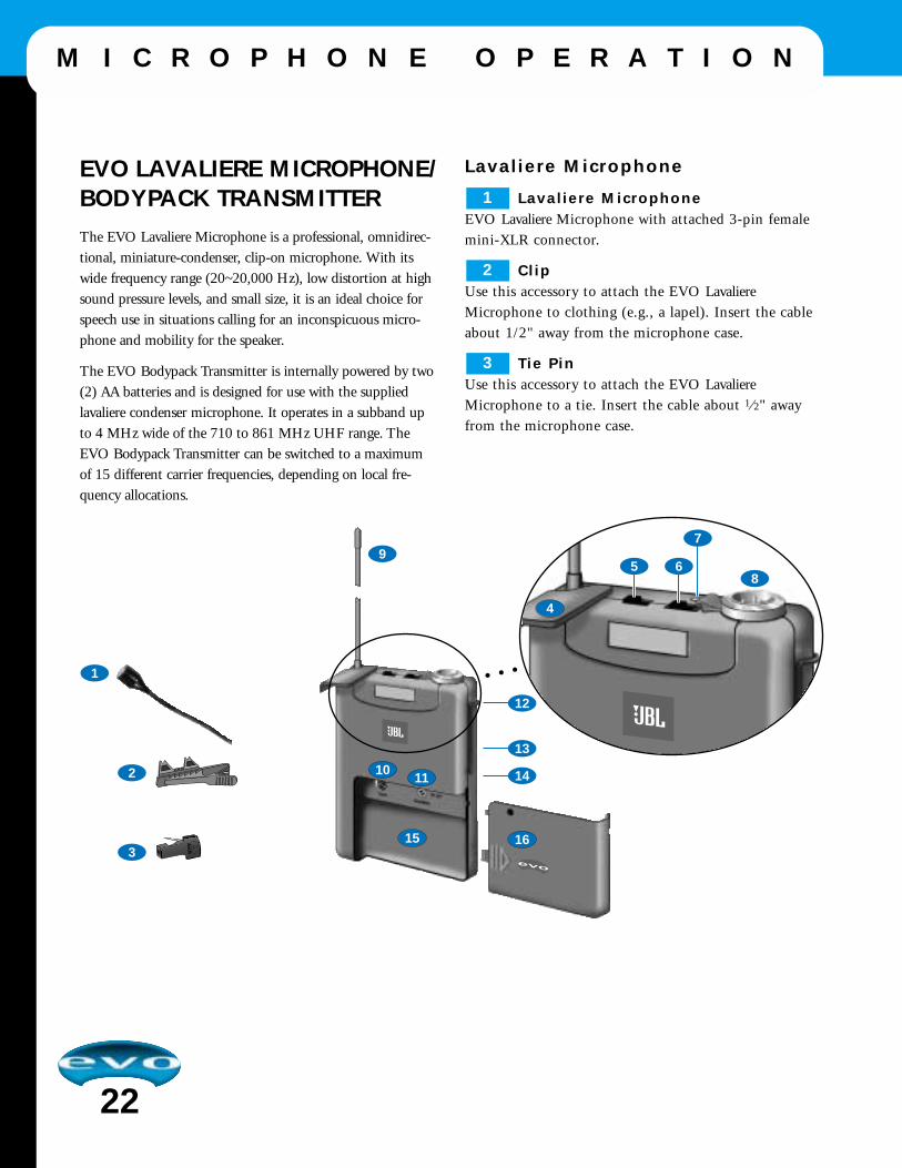
EVO LAVALIERE MICROPHONE/BODYPACK TRANSMITTERThe EVO Lavaliere Microphone is a professional, omnidirec-tional, miniature-condenser, clip-on microphone. With itswide frequency range (20~20,000 Hz), low distortion at highsound pressure levels, and small size, it is an ideal choice forspeech use in situations calling for an inconspicuous micro-phone and mobility for the speaker.
The EVO Bodypack Transmitter is internally powered by two(2) AA batteries and is designed for use with the suppliedlavaliere condenser microphone. It operates in a subband upto 4 MHz wide of the 710 to 861 MHz UHF range. TheEVO Bodypack Transmitter can be switched to a maximumof 15 different carrier frequencies, depending on local fre-quency allocations.
Lavaliere Microphone
Lavaliere MicrophoneEVO Lavaliere Microphone with attached 3-pin femalemini-XLR connector.
ClipUse this accessory to attach the EVO LavaliereMicrophone to clothing (e.g., a lapel). Insert the cableabout 1/2" away from the microphone case.
Tie PinUse this accessory to attach the EVO LavaliereMicrophone to a tie. Insert the cable about 1 ⁄2" awayfrom the microphone case.
3
2
1
1011
15
4
9
1
3
2
12
13
14
16
58
6
7

Bodypack Transmitter
Security CoverProtects the POWER and MIC switches from beingactuated unintentionally.
MICSlide the switch to 0 to mute the audio signal while powerand carrier frequency remain on. Thus, no noise will becomeaudible if you mute the microphone, even if the SQUELCH
control on the EVO wireless receiver is set to minimum.
POWERSlide the switch to turn the transmitter power on (I) or off (0).
Status LEDIndicates battery status and audio input overload. If the LEDis constantly lit, the batteries will be dead in about 90 min-utes. If the LED flashes, the audio input is being overloaded.
Audio Input3-pin male mini-XLR connector for connection to the EVOLavaliere Microphone.
AntennaPermanently connected, flexible antenna.
GAINUse the rotary GAIN control to match the microphone’s level tothe transmitter’s audio section. It is also accessible when thebattery door is on.
CHANNELUse the rotary CHANNEL switch to select a desired carrier frequency for transmission.
IMPORTANT: Be sure to switch POWER to off before
selecting a CHANNEL.
Belt ClipUse the Belt Clip to attach the transmitter to your belt in oneof four ways, as shown in Figure 5 (on the right).
Carrier Frequency TableA label lists available frequencies and is affixed to the rearpanel of the bodypack transmitter.
Figure 5 The Belt Clip can be positioned on the EVO Bodypack
Transmitter in four ways.
Frequency Set DesignationThe same label (on the rear panel) also indicates thedesignation of the Frequency Set.
Battery CompartmentSee Setting Up on page 8
Battery DoorSee Setting Up on page 8
16
15
14
13
12
11
10
9
8
7
6
5
4
23
M I C R O P H O N E O P E R A T I O N
12
12

EVO WIRELESS RECEIVERSYSTEM CONTROLLERThe EVO Wireless Receiver System Controller consists of apair of stationary true-microcontrolled diversity receivers for
use with EVO microphone transmitters. Each EVO WirelessReceiver operates in a subband of up to 4 MHz wide acrossthe 710 MHz to 861 MHz UHF range. Each unit can beswitched to a maximum of 15 different carrier frequencies,depending on local frequency allocations.
24
M I C R O P H O N E O P E R A T I O N
BALANCED UNBALANCED
BALANCEDLINE MIC
POWERAC/DC 12-16 V
20 mASet: XXXX
SNR: XXXXX
For IM-free frequenciesrefer to manual
1
2 3 68
9
4 5 7
13 15
16
1412
1
Front Panel
Rear Panel
Securing thePower Cord
10 11

Front Panel
AntennasEach EVO Wireless Receiver uses two antennas for diversityin order to receive the transmitter signal at two differentspots. The diversity electronics will automatically activate theantenna that delivers the better signal.
POWERPress this switch to turn the controller’s power on or off.
SQUELCH The squelch circuit switches the receiver off if the received sig-nal is too weak, in order to suppress related or residual noisewhile the transmitter is off. Set the SQUELCH control to min-imum before first switching the receiver on.
MUTE LEDThe MUTE LED turns on red if the squelch is active. In thiscase, the audio output will be muted.
NOTE: The MUTE LED does not indicate the position of the MUTE
switch on a microphone transmitter.
RF LOW/OK LEDsIndicate the received field strength of the transmitter signal.
DIVERSITY A/B LEDsIndicate which of the two receiving antennas is active.
AF/PEAK LEDsIndicate the received audio level. Optimum modulationoccurs when the green LED is on and the red LED flashesoccasionally. If the LEDs do not light, the sensitivity settingon the transmitter is too low. If the red LED is constantly on,overmodulation is occurring.
CHANNELUse the CHANNEL rotary switch to select the desired carrierfrequency or alternative frequencies.
VOLUMEUse the VOLUME control to match an EVO WirelessReceiver’s output level to an input channel’s sensitivity on theEVO mixer.
Rear Panel
Carrier Frequency TableA label (on the bottom) lists available Carrier Frequencies.
Frequency Set DesignationThe label (on the rear panel) lists the Frequency Set for this receiver.
AUDIO OUT (Balanced)Balanced 3-pin male XLR audio output for connection to abalanced audio input (e.g., a MIC input on the EVO mixer).
AUDIO OUT (Unbalanced)Unbalanced audio output on a 1 ⁄4" mono jack for connectionto an unbalanced audio input (e.g., a guitar amplifier).
BALANCED LINE/MICUse the BALANCED LINE/MIC switch to set AUDIO OUT
(Balanced) to line or microphone level.
POWERInput connector for the supplied ac adapter.
ScrewdriverIf desired, use the Screwdriver to adjust CHANNEL and GAIN
controls on microphone transmitters.
16
15
14
13
12
11
10
9
8
7
6
5
4
3
2
1
25
M I C R O P H O N E O P E R A T I O N

26
A P P L I C A T I O N S
BA
LAN
CE
DU
NB
ALA
NC
ED
BA
LAN
CE
DLI
NE
MIC
PO
WE
RA
C/D
C 1
2-16
V20
mA
Set
: X
XX
X
SN
R:
XX
XX
X
For
IM
-fre
e fr
eque
ncie
sre
fer
to m
anua
l
BA
LAN
CE
DU
NB
ALA
NC
ED
BA
LAN
CE
DLI
NE
MIC
PO
WE
RA
C/D
C 1
2-16
V20
mA
Set
: X
XX
X
SN
R:
XX
XX
X
For
IM
-fre
e fr
eque
ncie
sre
fer
to m
anua
l
H O U S E O F W O R S H I P

27
A P P L I C A T I O N S
BA
LAN
CE
DU
NB
ALA
NC
ED
BA
LAN
CE
DLI
NE
MIC
PO
WE
RA
C/D
C 1
2-16
V20
mA
Set
: X
XX
X
SN
R:
XX
XX
X
For
IM
-fre
e fr
eque
ncie
sre
fer
to m
anua
l
BA
LAN
CE
DU
NB
ALA
NC
ED
BA
LAN
CE
DLI
NE
MIC
PO
WE
RA
C/D
C 1
2-16
V20
mA
Set
: X
XX
X
SN
R:
XX
XX
X
For
IM
-fre
e fr
eque
ncie
sre
fer
to m
anua
l
L I V E P E R F O R M A N C E

This Troubleshooting section specifically concerns the operationof the EVO Mixer and EVO Microphones.
For problems associated specifically with EVOi.324Loudspeakers and the integrated EVOi.net please refer to theTroubleshoot Sections in each User's Guide respectively.
The EVO Mixer Station Doesn't Power Up:
Check that the AC mains supply is present. Check that themains voltage selection is correct for your country.
Check that the AC mains power cord is firmly connected.
Check the AC mains fuse.
If none of the above provide a solution then contact yourDealer.
My condenser microphone is not working:
Check that the 48V phantom power is on.
Make sure the mic is plugged into the Mic input.
Make sure that the mic cable is a balanced 3-wire type.
The Meters don't show any signal:
Check that the input gain has been set correctly.
Make sure that the source is connected to the appropriate inputsocket for the level of signal.
Do you have something connected on the Inserts, and is thatexternal device switched on?
Are the Master faders set at max., are input faders set highenough and is the channel routed to the output being moni-tored?
Check that the Mute switch is not engaged on the relevantchannel.
Is the appropriate monitor select switch pressed?
Is there a SOLO or AFL pressed on another channel?
There is no Mix output:
Check that the Mix Master fader is up.
Do you have something connected on the Mix Inserts, and isthat external device switched on?
There is no Monitor output:
Is the monitor control set high enough?
Is the appropriate monitor select switch pressed?
My headphones are distorting:
Check that the Phones level is not set too high.
Are the headphones less than 200 ohm impedance?
How do I prevent my wireless microphonesfrom cutting out, clicking, and generally beingnoisy:
Try to keep a minimum transmitter to receiver distance of 16ft(5m).
Make sure the transmitter is never more than 164ft (50m) fromthe receiver.
Keep the two transmitters at least 40” (1m) apart, and checkbefore the performance what frequency to set each to for bestoperation.
Make sure that the Bodypack transmitter antenna hangs freely,and doesn't make contact with the user’s skin. The human bodyattenuates RF signals.
Always use fresh batteries before a performance!
The Reception on the selected carrier frequencyis disrupted:
Change the carrier frequencies. Make sure these are at least onestep up or down from each other. This is necessary to providethe minimum frequency spacing required for intermodulation-free operation.
IMPORTANT: Make sure the Transmitter and the Receiver areboth switched OFF when changing the carrier frequency. Thenew, selected carrier frequency is activated when the Transmitteris switched back ON.
28
T R O U B L E S H O O T I N G

29
T E C H N I C A L D ATA
E V O i . s y s S p e c i f i c a t i o n s
NoiseMeasured RMS 20 Hz to 20 kHz Bandwidth
Mic. E.I.N. @ max gain 150W source impedance -129 dBuAux, Mix & Masters @ max.,
16 inputs routed with faders, pots down < -80 dBu
Crosstalk (@l kHz, typical) Channel Mute < 96 dBFader cut-off (rel. 0 mark) < 90 dB
Routing Isolation < 90 dBAux Send pots offness < 84 dB
Frequency ResponseMic/Line Input to any output 20 Hz - 30 kHz < .05 dB
THD + NMic sens. -30 dBu, + 14 dBu at all outputs @ l kHz < 0.009%
Input & Output ImpedanceMic Input 1.8 kWLine Input 10 kW
Stereo Return Input (Balanced jack) 10 kW2TK Return (Unbalanced RCA Phono) 12 kW
Mix, Aux, Direct Outputs, and Insert Sends 75 W
Input and Output LevelsMic Input max. level +22 dBuLine Input max. level < +30 dBu
Stereo Return Input max. level < +30 dBuHeadphones (@ 200 Ohms) 150 mW

30
T E C H N I C A L D A T A
710 to 860 MHz
FM
50-20.000 Hz
+/- 10 ppm
30kHz
< 0.5%
Yes
typ 50 dB(A)
10mW
typ 130 mA
2 x AA
>10h
350mV/ 1 kHz
220v.Ohm
240 x 36 mm (9.45 x 14.17 in.)
245 g (9.8 oz.)
710 to 860 MHz
FM
50-20.000 Hz
+/- 10 ppm
30kHz
< 0.5%
Yes
typ 50 dB(A)
Yes
10mW
typ 130 mA
2 x AA
>8h
350mV/ 1 kHz
220v.OhmPin 3-6V/6k8
92 x 65 x 20 mm (3.62 x 2.56 x 0.79 in.)
76 g (3.04 oz.)
710 to 860 MHz
FM
50-20.000 Hz
< 0.4%
Yes
>100 dB(A)
Yes
typ 145 mA
typ. -95 dBm
-95 to -80 dBm
Balanced XLR: MIC/Line level switchable; typ.30 dB Unbalanced 1/4” Jack: 0 dBm XLR; 6 dBm
210 x 170 x 42 mm (8.27 x 6.70 x 1.65 in.)
470 g (18.8 oz.)
Carrier Frequency
Modulation FM
Audio Bandwidth
Frequency Stability(-10 degrees C to +45 C degrees ETS +30degrees C to +60 degrees C FCC)
Rated devation
T.H.D. at 1 kHz
Compander Characteristics
S/N Ratio
Limiter
RF-Output
Current Consumption
Power Requirement
Battery Life
Input Sensitivity
Audio Input-related Deviation
Input Impendance
Phantom Power
Squelch Threshold
Audio Output
Size (W x D x H)
Net Weight g (oz)
HANDHELD BODYPACK RECEIVER
UHF Transmitters
E V O M i c r o p h o n e s - W i r e l e s s

31
T E C H N I C A L D A T A
D y n a m i c P r e s s u r e G r a d i e n t M i c r o p h o n e
Polar pattern: SupercardioidFrequency range: 60 to 20,000 Hz; at 1 cm: 20 to 20,000 Hz
Sensitivity at 1000 Hz: 2.5 mV/Pa (-52 dBV) re 1 V/PaImpedance at 1000 Hz: <600 ohms
Recommended load impedance: >2000 ohmsMax. SPL for 1 % (3 %) THD: 147 dB SPL (156 dB SPL)
Equivalent noise level: 22 dB(A) (DIN 45412)Environment: Temperature: -10º C to +60º C
Rel. humidity at +20º C: 95 %Connector: 3-pin XLR
Connector pinout: Pin 1 groundPin 2 hotPin 3 return
Case material: Die-cast zinc alloy

32
W A R R A N T Y
JBL Limited WarrantyThe JBL Limited Warranty on professional loudspeaker prod-ucts (except for enclosures) remains in effect for five years fromthe date of the first consumer purchase. JBL amplifiers are war-ranted for three years from the date of original purchase.Enclosures and all other JBL products are warranted for twoyears from the date of original purchase.
Who Is Protected by This Warranty?Your JBL Warranty protects the original owner and all subse-quent owners so long as: A.) Your JBL product has been pur-chased in the Continental United States, Hawaii or Alaska.(This Warranty does not apply to JBL products purchased else-where except for purchases by military outlets. Other pur-chasers should contact the local JBL distributor for warrantyinformation.); and B.) The original dated bill of sale is present-ed whenever warranty service is required.
What is Covered by the JBL Warranty?Except as specified below, your JBL Warranty covers all defectsin material and workmanship. The following are not covered:Damage caused by accident, misuse, abuse, product modifica-tion or neglect; damage occurring during shipment; damageresulting from failure to follow instructions contained in yourInstruction Manual; damage resulting from the performance ofrepairs by someone not authorized by JBL; claims based uponany misrepresentations by the seller; any JBL product on whichthe serial number has been defaced, modified or removed.
Who Pays for What?JBL will pay all labor and material expenses for all repairs cov-ered by this warranty. Please be sure to save the original ship-ping cartons because a charge will be made if replacement car-tons are requested. Payment of shipping charges is discussed inthe next section of this warranty.
How to Obtain Warranty PerformanceIf your JBL product ever needs service, write or telephone us atJBL Incorporated (Attn: Customer Service Department), 8500Balboa Boulevard, PO. Box 2200, Northridge, California91329 (818/893-8411). We may direct you to an authorizedJBL Service Agency or ask you to send your unit to the factory
for repair Either way, you'll need to present the original bill ofsale to establish the date of purchase. Please do not ship yourJBL product to the factory without prior authorization. If transportation of your JBL product presents any unusual difficulties, please advise us and we may make special arrange-ments with you. Otherwise, you are responsible for transport-ing your product for repair or arranging for its transportationand for payment of any initial shipping charges. However, wewill pay the return shipping charges if repairs are covered bythe warranty.
Limitation of Implied WarrantiesALL IMPLIED WARRANTIES, INCLUDING WAR-RANTIES OF MERCHANTABILITY AND FITNESS FORPARTICULAR PURPOSE, ARE LIMITED IN DURATIONTO THE LENGTH OF THIS WARRANTY.EXCLUSION OF CERTAIN DAMAGESJBL'S LIABILITY IS LIMITED TO THE REPAIR ORREPLACEMENT, AT OUR OPTION, OF ANY DEFEC-TIVE PRODUCT AND SHALL NOT INCLUDE INCI-DENTAL OR CONSEQUENTIAL DAMAGES OF ANYKIND. SOME STATES DO NOT ALLOW LIMITATIONSON HOW LONG AN IMPLIED WARRANTY LASTSAND/OR DO NOT ALLOW THE EXCLUSION OF INCIDENTAL OR CONSEQUENTIAL DAMAGES, SOTHE ABOVE LIMITATIONS AND EXCLUSIONS MAYNOT APPLY TO YOU. THIS WARRANTY GIVES YOUSPECIFIC LEGAL RIGHTS, AND YOU MAY ALSO HAVE OTHER RIGHTS WHICH VARY FROM STATE TO STATE.
JBL Professional Contact InformationMailing AddressJBL Professional8500 Balboa Blvd.Northridge California 91329
Customer Service Monday through Friday 8:00am - 5:00pm Pacific Coast Time
In the U.S.A. (800) 8JBLPRO (800.852.5776)On the World Wide Web: http://www.jblpro.com

Applications ...26AUX sends ...11Bargraph meters ...17Connections
Microphones ...7, 8Power ...5Network ...6Speakers ...6
Design Overview ...4DIR (Direct output) ...13Equalizer ...11FCC Statement ...4Headphones ...17Hooking up the system ...9, 26House of Worship Applications ...26INS (Insert point) ...13Initial Settings ...9Lexicon Effects ...11, 14, 15Lexicon Mute ...15Line inputs ...10Live Performance Applications ... 27Master section ...14Microphones
Connections ...7, 8Features ...18Input settings ...10Operation ...19Phantom power ...10, 16Wireless ...4, 8, 21Wireless lavaliere ...22Wireless Receiver ...24
Mixer featuresAUX sends ...11Bargraph meters ...17100 Hz Hi pass filter ...11DIR (Direct output) ...13Equalizer ...11Headphones ...17Input channels ...10INS (Insert point) ...13Lexicon Effects ...11, 14, 15Master section ...14Monitors ...17Mute control ...12Pan Control ...12RET (returns) ...15Setting the initial mix ...9SOLO button ...13Specifications ...29SUB busses ...2Mute control ...12
Packaging contents ...3Pan Control ...12Phantom power ...10, 16Phones ...17Power connections ...5, 9RET (returns) ...15Set-up ...26SOLO button ...13Speakers (Also see EVOi.324 manual)
Connecting ...6, 26Specifications ...29
SUB busses ...12System Set-up ...9, 26Testing the system ...9Trouble shooting ...28Using the manual ...3Warranty (US) ...32Wireless microphones ...4, 8, 22, 30Wireless Receiver ...24
33
I N D E X

A Harman International Company
JBL Professional • 8500 Balboa Boulevard • Northridge, CA 91329www.jblpro.com
Part # 337539-001© Copyright 2001 JBL Professional • Printed in the USA