evs27 the value of a clutch mechanism in evsepg.eng.ox.ac.uk/sites/default/files/robert/evs27_the...
TRANSCRIPT
EVS27 International Battery, Hybrid and Fuel Cell Electric Vehicle Symposium 1
EVS27 Barcelona, Spain, November 17-20, 2013
The Value of a Clutch Mechanism in Electric Vehicles
R. Camilleri 1, P. Armstrong, N. Ewin, R. Richardson, D.A. Howey, M.D. McCulloch
Energy and Power Group, Dept. of Engineering Science, University of Oxford, [email protected]
Abstract This paper examines the benefits of a drivetrain that is able to disengage its propulsion motor from the
driveline in an electric vehicle. The drivetrain was developed for an ultra-efficient eco vehicle competing in
the Shell 2013 Eco Marathon. Various clutch mechanisms were examined. In spite of the complexity and
losses associated with additional bearings and release surfaces, an actuated dog clutch was chosen as it
offers superior performance due to the dual capability of freewheeling and regenerative braking that results.
Track data from the event is presented along with experimental work that indicates that the clutch
mechanism reduces power consumption by more than 35% for a ferrous permanent magnet propulsion
motor. Savings were reduced to 5% for a coreless permanent magnet motor coupled to the driveline via an
11:1 straight cut spur gear arrangement. This reduced saving was due to the removal of hysteresis and eddy
current losses from the stator. The paper also demonstrates during a competition in which the driver was
aware of the energy consumption, the driving style changed when the technological option to free wheel
was available. Finally the study was inferred onto a real world application with further experimental and
simulation work on the Delta E4 Coupe, a high performance electric sports car. The vehicle uses a ferrous
permanent magnet direct drive arrangement, indicated a reduction in power consumption of 10 to 14%. It is
hoped that these insights are relevant when considering the development of electric vehicle drivetrains
where machine topology and drive cycle will determine the value of a clutch mechanism.
Keywords: Free wheeling, clutch mechanism, ultra-low energy electric vehicle
Nomenclature Roman Symbols a, ! acceleration [m/s2] A frontal area [m2] C1, C2, C3, constants Cd drag coefficient Ek kinetic energy [J] F force [N] g acceleration due to gravity [m/s2] I moment of inertia [ ]
m mass [kg] P power [W] r radius [m] RR rolling resistance coefficient t time [s] v, ! velocity [m/s] x distance [m] Greek Symbols θ angle of incline [o] ρ density [kg/m3]
EVS27 International Battery, Hybrid and Fuel Cell Electric Vehicle Symposium 2
ω, Ω angular velocity [rad/s] Roman Subscripts L losses v vehicle
1 Introduction As Electric Vehicles (EVs) become smaller and more efficient, idling losses such as those associated with bearings, gear meshes, permanent magnet motor iron losses and windage, become increasingly dominant [1]. As a result, the motivation to disengage the propulsion system from the wheels during a coasting event increases. The benefits of so called “pulse and glide” driving strategies, whereby a vehicle accelerates prior to freewheeling, with respects to conventional IC engines and hybrid electric drivetrains has been demonstrated in [2]. However, there seems to be little literature regarding the freewheeling performance of electric vehicles and implication on driveline component selection. This paper examines a drivetrain developed for a single seat, battery electric, carbon fibre vehicle weighing 30kg called Peggie. Peggie competed in the 2013 Shell Eco Marathon. The drivetrain is able to disengage the propulsion motor allowing the vehicle to freewheel during coasting events. The performance of the clutch mechanism within Peggie is compared with the predicted performance on a larger vehicle, the 1000kg Delta E4 coupe based on coast down measurements taken from its drivetrain.
2 An Ultra Low Energy Electric Vehicle
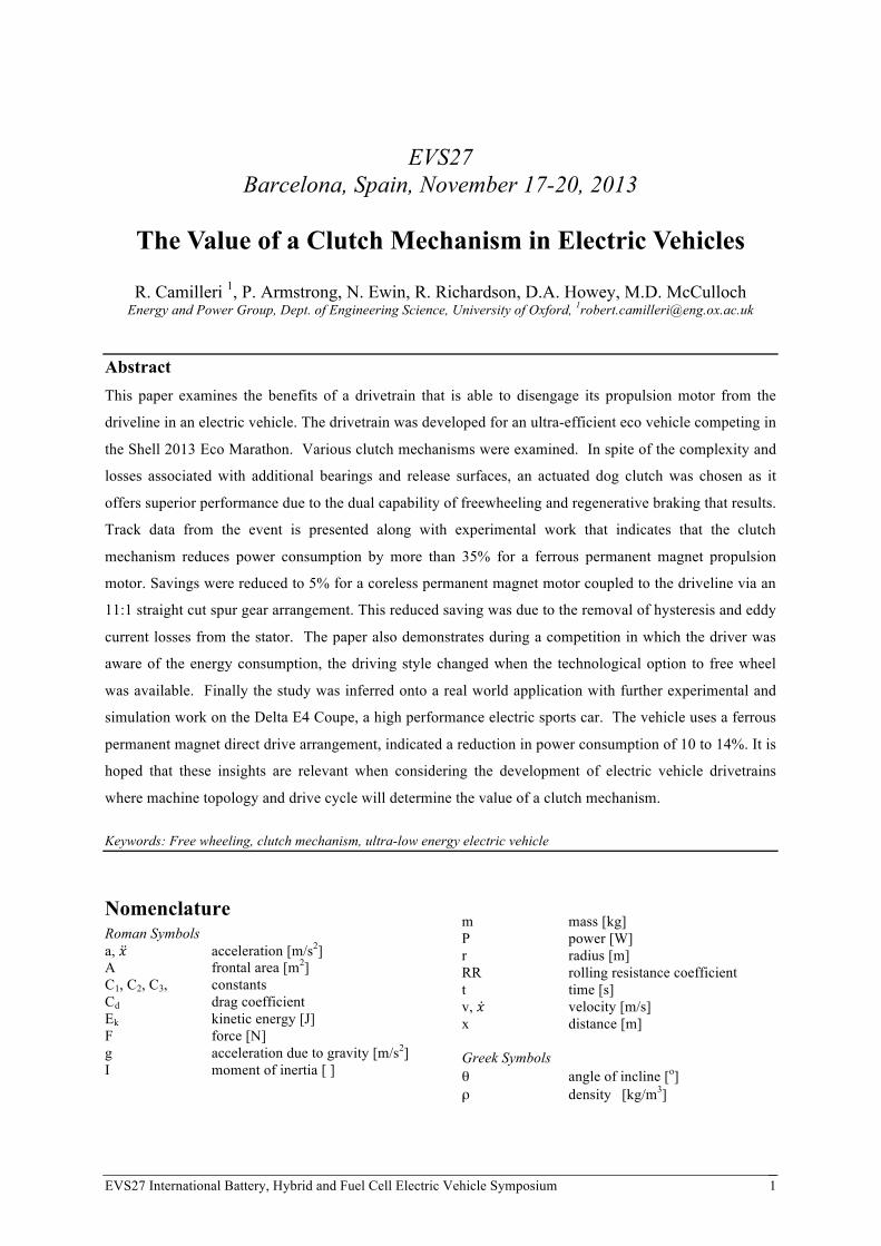
2.1 Description of the Vehicle This section describes the ultra low energy electric vehicle, affectionately called Peggie and shown in Figure 1. The vehicle is a single seat, battery electric vehicle developed in order to participate in the Shell Eco Marathon [3]. The aim of the competition is to have the vehicle finish 10 laps of 1.6 km track in less than 39mins, with the least amount of energy consumption. PEGGIE debuted in 2012 and participated again in 2013. The vehicle comprises of a monocoque carbon fibre body, weighing approx. 30kg. The vehicle is designed with an aerodynamic profile based on the Morelli profile [4] that aims at minimising aerodynamic
drag by balancing form and skin drag components. It has 2 wheels at the front and a single steerable wheel at the back. In addition to steering, the rear wheel also delivers propulsion to the vehicle.
Figure 1: Photograph of PEGGIE, an ultra-low energy EV
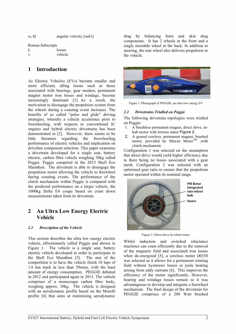
2.2 Drivetrains Trialled on Peggie The following drivetrain topologies were trialled on Peggie: 1. A brushless permanent magnet, direct drive, in-
hub motor with ferrous stator Figure 2. 2. A geared coreless, permanent magnet, brushed
motor, provided by Maxon MotorTM ,with clutch mechanism
Configuration 1 was selected on the assumption that direct drive would yield higher efficiency due to there being no losses associated with a gear mesh. Configuration 2 was selected with an optimised gear ratio to ensure that the propulsion motor operated within its nominal range.
Figure 2: Direct drive In-wheel motor
Whilst induction and switched reluctance machines can coast efficiently due to the removal of the magnetic field and associated iron losses when de-energized [5], a coreless motor (RE50 was selected as it allows for a permanent rotating field without hysteresis losses or joule heating arising from eddy currents [6]. This improves the efficiency of the motor significantly. However, bearing and windage losses remain so it was advantageous to develop and integrate a freewheel mechanism. The final design of the drivetrain for PEGGIE comprises of a 200 Watt brushed
!
Stator
PM(Rotor(integrated(into(wheel(hub
EVS27 International Battery, Hybrid and Fuel Cell Electric Vehicle Symposium 3
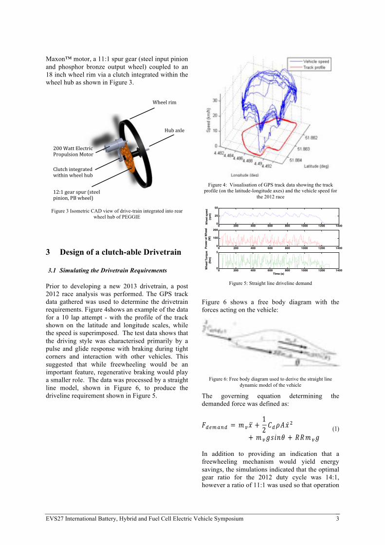
Maxon™ motor, a 11:1 spur gear (steel input pinion and phosphor bronze output wheel) coupled to an 18 inch wheel rim via a clutch integrated within the wheel hub as shown in Figure 3.
Figure 3 Isometric CAD view of drive-train integrated into rear
wheel hub of PEGGIE
3 Design of a clutch-able Drivetrain 3.1 Simulating the Drivetrain Requirements
Prior to developing a new 2013 drivetrain, a post 2012 race analysis was performed. The GPS track data gathered was used to determine the drivetrain requirements. Figure 4shows an example of the data for a 10 lap attempt - with the profile of the track shown on the latitude and longitude scales, while the speed is superimposed. The test data shows that the driving style was characterised primarily by a pulse and glide response with braking during tight corners and interaction with other vehicles. This suggested that while freewheeling would be an important feature, regenerative braking would play a smaller role. The data was processed by a straight line model, shown in Figure 6, to produce the driveline requirement shown in Figure 5.
Figure 4: Visualisation of GPS track data showing the track
profile (on the latitude-longitude axes) and the vehicle speed for the 2012 race
Figure 5: Straight line driveline demand
Figure 6 shows a free body diagram with the forces acting on the vehicle:
Figure 6: Free body diagram used to derive the straight line
dynamic model of the vehicle
The governing equation determining the demanded force was defined as:
!!"#$%! = ! !! +12 !!!"!
!
+ ! !!"#$% + !!! !! (1)
In addition to providing an indication that a freewheeling mechanism would yield energy savings, the simulations indicated that the optimal gear ratio for the 2012 duty cycle was 14:1, however a ratio of 11:1 was used so that operation
12:1$gear$spur$(steel$pinion,$PB$wheel)
200$Watt$Electric$Propulsion$Motor
Wheel$rim
Hub$axle
Clutch$integrated$within$wheel$hub
EVS27 Design, Development and Testing of a Powertrain for an Ultra Efficient Battery Electric Vehicle. - Abstract 2
in section 2, was undertaken to determine whether there was a net benefit against the mass penalty associated with an actuated sprung dog hub clutching mechanism.
Figure 1 (Left) Photograph of PEGGIE Ultra low energy electric vehicle, (right) illustration of drive-train associated with rear wheel
2 Vehicle Simulation to Determine Value of Freewheel Capability
2.1 Driveline Requirements The driveline requirements were derived from GPS track data gathered whilst the vehicle competed during the 2012 competition in Rotterdam:
Figure 2 Driveline demand at the wheel
The driving style was characterised primarily by a pulse and glide response with occasional braking during tight corners and interaction with other vehicles. This suggested that regenerative braking would play a marginal role whilst freewheeling would be an important feature.
2.2 Driveline Simulation and Results The track data from Figure 2 was processed by a dynamic straight line model of the vehicle. Figure 3 shows the aerodynamic drag, rolling, inertial, spinning and gravitational loading which the vehicle was subjected to:
Figure 3 Free body diagram used to derive straight line dynamic model of vehicle
From Figure 3, the following differential equation was derived and simulated:
0 200 400 600 800 1000 1200 14000
25
50W
heel
spe
ed(rp
m)
0 200 400 600 800 1000 1200 14000
100
200
Powe
r at W
heel
(W)
0 200 400 600 800 1000 1200 14000
5
Time (s)
Whe
el T
orqu
e(N
m)
EVS27 International Battery, Hybrid and Fuel Cell Electric Vehicle Symposium 4
of the vehicle was within the speed constraint posed by the MaxonTM RE50 coreless propulsion motor. 3.2 Specifying a clutch mechanism
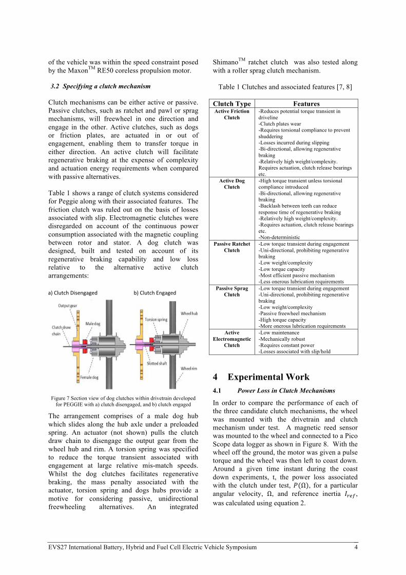
Clutch mechanisms can be either active or passive. Passive clutches, such as ratchet and pawl or sprag mechanisms, will freewheel in one direction and engage in the other. Active clutches, such as dogs or friction plates, are actuated in or out of engagement, enabling them to transfer torque in either direction. An active clutch will facilitate regenerative braking at the expense of complexity and actuation energy requirements when compared with passive alternatives. Table 1 shows a range of clutch systems considered for Peggie along with their associated features. The friction clutch was ruled out on the basis of losses associated with slip. Electromagnetic clutches were disregarded on account of the continuous power consumption associated with the magnetic coupling between rotor and stator. A dog clutch was designed, built and tested on account of its regenerative braking capability and low loss relative to the alternative active clutch arrangements:
Figure 7 Section view of dog clutches within drivetrain developed
for PEGGIE with a) clutch disengaged, and b) clutch engaged
The arrangement comprises of a male dog hub which slides along the hub axle under a preloaded spring. An actuator (not shown) pulls the clutch draw chain to disengage the output gear from the wheel hub and rim. A torsion spring was specified to reduce the torque transient associated with engagement at large relative mis-match speeds. Whilst the dog clutches facilitates regenerative braking, the mass penalty associated with the actuator, torsion spring and dogs hubs provide a motive for considering passive, unidirectional freewheeling alternatives. An integrated
ShimanoTM ratchet clutch was also tested along with a roller sprag clutch mechanism.
Table 1 Clutches and associated features [7, 8]
Clutch Type Features Active Friction
Clutch -Reduces potential torque transient in driveline -Clutch plates wear -Requires torsional compliance to prevent shuddering -Losses incurred during slipping -Bi-directional, allowing regenerative braking -Relatively high weight/complexity. Requires actuation, clutch release bearings etc.
Active Dog Clutch
-High torque transient unless torsional compliance introduced -Bi-directional, allowing regenerative braking -Backlash between teeth can reduce response time of regenerative braking -Relatively high weight/complexity. -Requires actuation, clutch release bearings etc. -Non-deterministic
Passive Ratchet Clutch
-Low torque transient during engagement -Uni-directional, prohibiting regenerative braking -Low weight/complexity -Low torque capacity -Most efficient passive mechanism -Less onerous lubrication requirements
Passive Sprag Clutch
-Low torque transient during engagement -Uni-directional, prohibiting regenerative braking -Low weight/complexity -Passive freewheel mechanism -High torque capacity -More onerous lubrication requirements
Active Electromagnetic
Clutch
-Low maintenance -Mechanically robust -Requires constant power -Losses associated with slip/hold
4 Experimental Work 4.1 Power Loss in Clutch Mechanisms
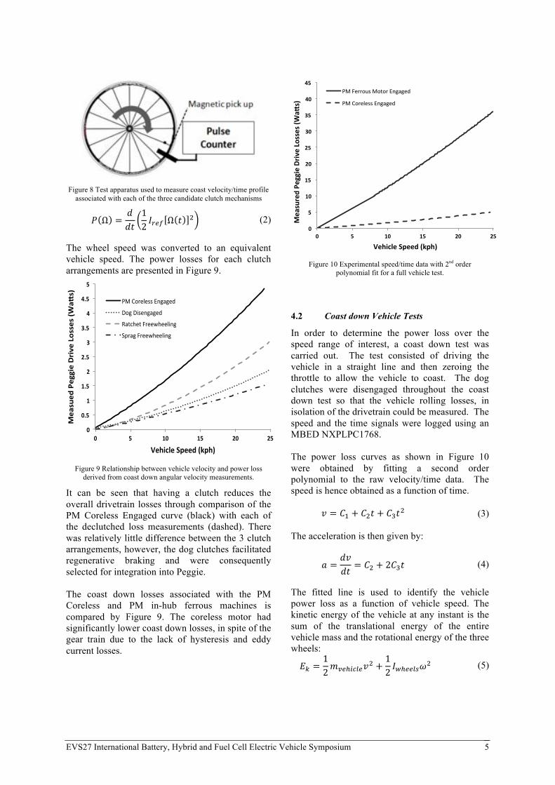
In order to compare the performance of each of the three candidate clutch mechanisms, the wheel was mounted with the drivetrain and clutch mechanism under test. A magnetic reed sensor was mounted to the wheel and connected to a Pico Scope data logger as shown in Figure 8. With the wheel off the ground, the motor was given a pulse torque and the wheel was then left to coast down. Around a given time instant during the coast down experiments, t, the power loss associated with the clutch under test, !(Ω), for a particular angular velocity, Ω, and reference inertia !!"#, was calculated using equation 2.
a)#Clutch#Disengaged# b)#Clutch#Engaged#
EVS27 International Battery, Hybrid and Fuel Cell Electric Vehicle Symposium 5
Figure 8 Test apparatus used to measure coast velocity/time profile associated with each of the three candidate clutch mechanisms
! Ω = !!"
12 !!"# Ω ! ! (2)
The wheel speed was converted to an equivalent vehicle speed. The power losses for each clutch arrangements are presented in Figure 9.
Figure 9 Relationship between vehicle velocity and power loss
derived from coast down angular velocity measurements.
It can be seen that having a clutch reduces the overall drivetrain losses through comparison of the PM Coreless Engaged curve (black) with each of the declutched loss measurements (dashed). There was relatively little difference between the 3 clutch arrangements, however, the dog clutches facilitated regenerative braking and were consequently selected for integration into Peggie. The coast down losses associated with the PM Coreless and PM in-hub ferrous machines is compared by Figure 9. The coreless motor had significantly lower coast down losses, in spite of the gear train due to the lack of hysteresis and eddy current losses.
Figure 10 Experimental speed/time data with 2nd order
polynomial fit for a full vehicle test.
4.2 Coast down Vehicle Tests
In order to determine the power loss over the speed range of interest, a coast down test was carried out. The test consisted of driving the vehicle in a straight line and then zeroing the throttle to allow the vehicle to coast. The dog clutches were disengaged throughout the coast down test so that the vehicle rolling losses, in isolation of the drivetrain could be measured. The speed and the time signals were logged using an MBED NXPLPC1768. The power loss curves as shown in Figure 10 were obtained by fitting a second order polynomial to the raw velocity/time data. The speed is hence obtained as a function of time.
! = !! + !!! + !!!! (3) The acceleration is then given by:
! = !"!" = !! + 2!!! (4)
The fitted line is used to identify the vehicle power loss as a function of vehicle speed. The kinetic energy of the vehicle at any instant is the sum of the translational energy of the entire vehicle mass and the rotational energy of the three wheels:
!! =12!!"!!"#$!! +
12 !!!!!"#!
! (5)
0"
0.5"
1"
1.5"
2"
2.5"
3"
3.5"
4"
4.5"
5"
0" 5" 10" 15" 20" 25"
Measued
"Peggie"Drive"Losses"(W
a9s)"
Vehicle"Speed"(kph)"
PM#Coreless#Engaged#
Dog#Disengaged#
Ratchet#Freewheeling#
Sprag#Freewheeling#
0"
5"
10"
15"
20"
25"
30"
35"
40"
45"
0" 5" 10" 15" 20" 25"
Measured"Pe
ggie"Driv
e"Losses"(W
a8s)"
Vehicle"Speed"(kph)"
PM#Ferrous#Motor#Engaged#
PM#Coreless#Engaged#
EVS27 International Battery, Hybrid and Fuel Cell Electric Vehicle Symposium 6
where !!"!!"#$ is the total vehicle mass, including driver, shell and wheels, ! is the vehicle speed, ω is the angular velocity of the wheels and !!!!!"# were derived from measurement. The power loss during coast could then be computed by equation 6:
! = !!!!"
(6)
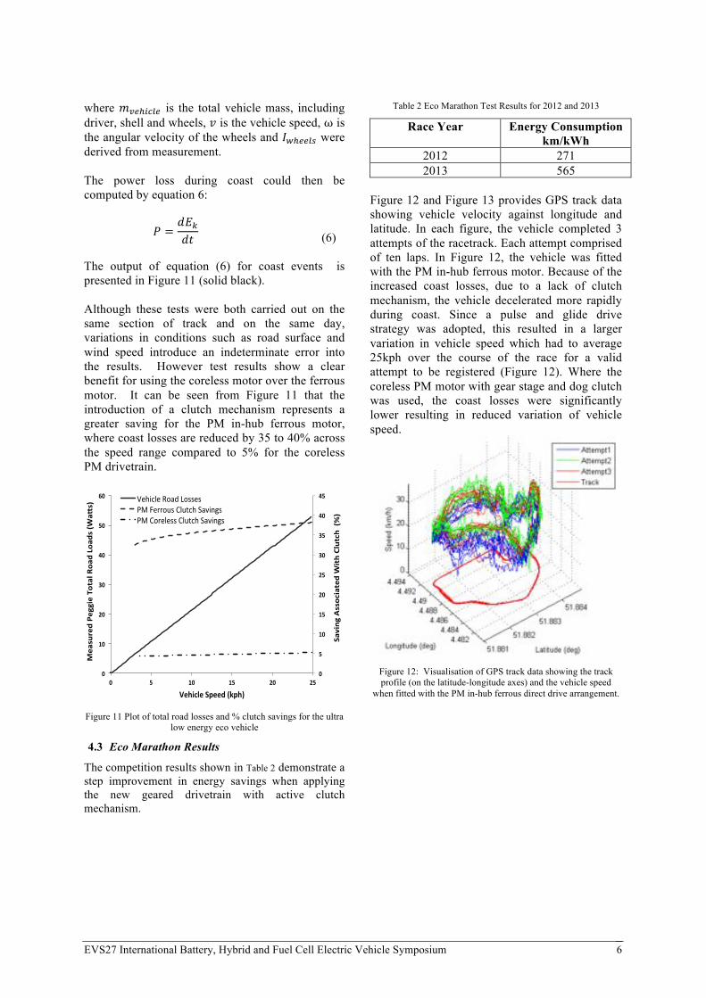
The output of equation (6) for coast events is presented in Figure 11 (solid black). Although these tests were both carried out on the same section of track and on the same day, variations in conditions such as road surface and wind speed introduce an indeterminate error into the results. However test results show a clear benefit for using the coreless motor over the ferrous motor. It can be seen from Figure 11 that the introduction of a clutch mechanism represents a greater saving for the PM in-hub ferrous motor, where coast losses are reduced by 35 to 40% across the speed range compared to 5% for the coreless PM drivetrain.
Figure 11 Plot of total road losses and % clutch savings for the ultra
low energy eco vehicle
4.3 Eco Marathon Results
The competition results shown in Table 2 demonstrate a step improvement in energy savings when applying the new geared drivetrain with active clutch mechanism.
Table 2 Eco Marathon Test Results for 2012 and 2013
Race Year Energy Consumption km/kWh
2012 271 2013 565
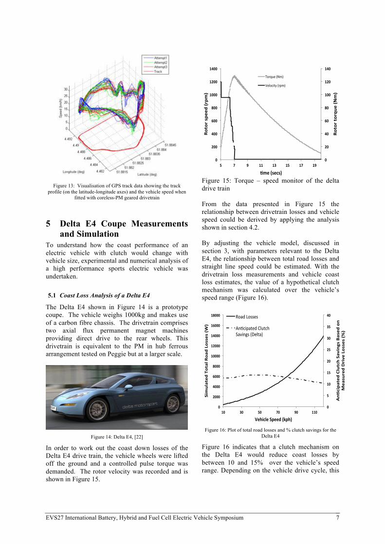
Figure 12 and Figure 13 provides GPS track data showing vehicle velocity against longitude and latitude. In each figure, the vehicle completed 3 attempts of the racetrack. Each attempt comprised of ten laps. In Figure 12, the vehicle was fitted with the PM in-hub ferrous motor. Because of the increased coast losses, due to a lack of clutch mechanism, the vehicle decelerated more rapidly during coast. Since a pulse and glide drive strategy was adopted, this resulted in a larger variation in vehicle speed which had to average 25kph over the course of the race for a valid attempt to be registered (Figure 12). Where the coreless PM motor with gear stage and dog clutch was used, the coast losses were significantly lower resulting in reduced variation of vehicle speed.
Figure 12: Visualisation of GPS track data showing the track profile (on the latitude-longitude axes) and the vehicle speed
when fitted with the PM in-hub ferrous direct drive arrangement.
0"
5"
10"
15"
20"
25"
30"
35"
40"
45"
0"
10"
20"
30"
40"
50"
60"
0" 5" 10" 15" 20" 25"
"Saving"Associated"With"Clutch""(%)"
Measured"Pe
ggie"Total"Roa
d"Load
s"(W
aDs)"
Vehicle"Speed"(kph)"
Vehicle'Road'Losses'PM'Ferrous'Clutch'Savings'PM'Coreless'Clutch'Savings'
EVS27 International Battery, Hybrid and Fuel Cell Electric Vehicle Symposium 7
Figure 13: Visualisation of GPS track data showing the track
profile (on the latitude-longitude axes) and the vehicle speed when fitted with coreless-PM geared drivetrain
5 Delta E4 Coupe Measurements and Simulation
To understand how the coast performance of an electric vehicle with clutch would change with vehicle size, experimental and numerical analysis of a high performance sports electric vehicle was undertaken.
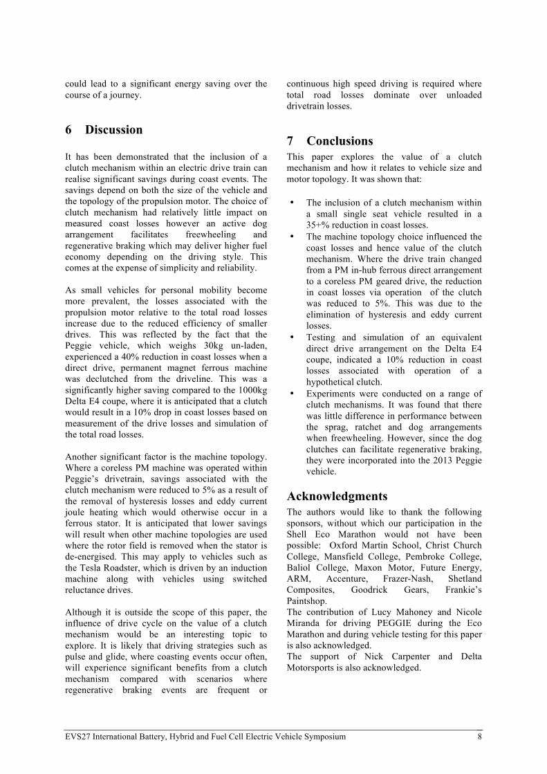
5.1 Coast Loss Analysis of a Delta E4
The Delta E4 shown in Figure 14 is a prototype coupe. The vehicle weighs 1000kg and makes use of a carbon fibre chassis. The drivetrain comprises two axial flux permanent magnet machines providing direct drive to the rear wheels. This drivetrain is equivalent to the PM in hub ferrous arrangement tested on Peggie but at a larger scale.
Figure 14: Delta E4, [22]
In order to work out the coast down losses of the Delta E4 drive train, the vehicle wheels were lifted off the ground and a controlled pulse torque was demanded. The rotor velocity was recorded and is shown in Figure 15.
Figure 15: Torque – speed monitor of the delta drive train From the data presented in Figure 15 the relationship between drivetrain losses and vehicle speed could be derived by applying the analysis shown in section 4.2. By adjusting the vehicle model, discussed in section 3, with parameters relevant to the Delta E4, the relationship between total road losses and straight line speed could be estimated. With the drivetrain loss measurements and vehicle coast loss estimates, the value of a hypothetical clutch mechanism was calculated over the vehicle’s speed range (Figure 16).
Figure 16: Plot of total road losses and % clutch savings for the
Delta E4
Figure 16 indicates that a clutch mechanism on the Delta E4 would reduce coast losses by between 10 and 15% over the vehicle’s speed range. Depending on the vehicle drive cycle, this
0"
20"
40"
60"
80"
100"
120"
140"
0"
200"
400"
600"
800"
1000"
1200"
1400"
5" 7" 9" 11" 13" 15" 17" 19"
Rotor"torqu
e"(Nm)"
Rotor"spe
ed"(rpm
)"
:me"(secs)"
Torque'(Nm)'
Velocity'(rpm)'
0"
5"
10"
15"
20"
25"
30"
35"
40"
0"
2000"
4000"
6000"
8000"
10000"
12000"
14000"
16000"
18000"
10" 30" 50" 70" 90" 110"
An.cipated
"Clutch"Savings"Based
"on"
Measured"Drive"Losses"(%)"
Simulated"Total"R
oad
"Losses"(W)"
Vehicle"Speed"(kph)"
Road%Losses%
An+cipated%Clutch%Savings%(Delta)%
EVS27 International Battery, Hybrid and Fuel Cell Electric Vehicle Symposium 8
could lead to a significant energy saving over the course of a journey.
6 Discussion It has been demonstrated that the inclusion of a clutch mechanism within an electric drive train can realise significant savings during coast events. The savings depend on both the size of the vehicle and the topology of the propulsion motor. The choice of clutch mechanism had relatively little impact on measured coast losses however an active dog arrangement facilitates freewheeling and regenerative braking which may deliver higher fuel economy depending on the driving style. This comes at the expense of simplicity and reliability. As small vehicles for personal mobility become more prevalent, the losses associated with the propulsion motor relative to the total road losses increase due to the reduced efficiency of smaller drives. This was reflected by the fact that the Peggie vehicle, which weighs 30kg un-laden, experienced a 40% reduction in coast losses when a direct drive, permanent magnet ferrous machine was declutched from the driveline. This was a significantly higher saving compared to the 1000kg Delta E4 coupe, where it is anticipated that a clutch would result in a 10% drop in coast losses based on measurement of the drive losses and simulation of the total road losses. Another significant factor is the machine topology. Where a coreless PM machine was operated within Peggie’s drivetrain, savings associated with the clutch mechanism were reduced to 5% as a result of the removal of hysteresis losses and eddy current joule heating which would otherwise occur in a ferrous stator. It is anticipated that lower savings will result when other machine topologies are used where the rotor field is removed when the stator is de-energised. This may apply to vehicles such as the Tesla Roadster, which is driven by an induction machine along with vehicles using switched reluctance drives. Although it is outside the scope of this paper, the influence of drive cycle on the value of a clutch mechanism would be an interesting topic to explore. It is likely that driving strategies such as pulse and glide, where coasting events occur often, will experience significant benefits from a clutch mechanism compared with scenarios where regenerative braking events are frequent or
continuous high speed driving is required where total road losses dominate over unloaded drivetrain losses.
7 Conclusions This paper explores the value of a clutch mechanism and how it relates to vehicle size and motor topology. It was shown that:
• The inclusion of a clutch mechanism within a small single seat vehicle resulted in a 35+% reduction in coast losses.
• The machine topology choice influenced the coast losses and hence value of the clutch mechanism. Where the drive train changed from a PM in-hub ferrous direct arrangement to a coreless PM geared drive, the reduction in coast losses via operation of the clutch was reduced to 5%. This was due to the elimination of hysteresis and eddy current losses.
• Testing and simulation of an equivalent direct drive arrangement on the Delta E4 coupe, indicated a 10% reduction in coast losses associated with operation of a hypothetical clutch.
• Experiments were conducted on a range of clutch mechanisms. It was found that there was little difference in performance between the sprag, ratchet and dog arrangements when freewheeling. However, since the dog clutches can facilitate regenerative braking, they were incorporated into the 2013 Peggie vehicle.
Acknowledgments The authors would like to thank the following sponsors, without which our participation in the Shell Eco Marathon would not have been possible: Oxford Martin School, Christ Church College, Mansfield College, Pembroke College, Baliol College, Maxon Motor, Future Energy, ARM, Accenture, Frazer-Nash, Shetland Composites, Goodrick Gears, Frankie’s Paintshop. The contribution of Lucy Mahoney and Nicole Miranda for driving PEGGIE during the Eco Marathon and during vehicle testing for this paper is also acknowledged. The support of Nick Carpenter and Delta Motorsports is also acknowledged.
EVS27 International Battery, Hybrid and Fuel Cell Electric Vehicle Symposium 9
References
[1] M. S. Carmeli, F. Castelli Dezza, G. Galmarini, M. Mauri and L. Piehari, A vehicle with very low fuel consumption; realization, analysis and optimization, in XIX International Conference on Electrical Machines, Rome, Italy, 2010, .
[2] J. Lee. , Vehicle Inertia Impact on Fuel Consumption of Conventional and Hybrid Electric Vehicles Ysing Acceleration and Coast Driving Strategy, Virginia Polytech, 2009.
[3] Shell. Shell Eco Marathon, http://www.shell.com/global/environment-society/ecomarathon.html, accessed on: 03/20, 2013.
[4] A. Morelli, A new aerodynamic approach to advanced automoile basic shapes, in SAE Technical Paper Series, Detroit, Michigan, March 6-9, 2000, pp. 2000-01-0491.
[5] M. Felden, P. Butterling, P. Jeck, L. Eckstein and K. Hameyer. Electric vehicle drive trains: From the specification sheet to the drive-train concept. Presented at Power Electronics and Motion Control Conference (EPE/PEMC), 2010 14th International. 2010, .
[6] Maxon Motors. Presentation on Maxon Coreless DC Permanent Magnet Motors, http://www.electromate.com/ftp/public/Maxon DC Motor Sizing Made Easy Presentation English Version March 2010/2_DcBldcMotor.pdf., accessed on: 3/21, 2013.
[7] G. Boka, J. Marialigeti, L. Lovas and B. Trencseni, Face dog clutch engagement at low mismatch speed,Periodica Polytechnica Transportation Engineering, Vol. 38, pp. 29, 2010.
[8] M. J. Neale, The Tribology Handbook, 2, Vol. 37, No. 159 ed.Anonymous Oxford: Betterworth Heinemann, 1996, pp. B6-B7.
[9] J. F. Gieras, R. J. Wang and M. J. Kamper, Axial Flux Permanent Magnet Brushless Machines. Springer Science, 2008.
EVS27 International Battery, Hybrid and Fuel Cell Electric Vehicle Symposium 10
Authors
Robert Camilleri graduated with a BEng (Hons) in Mechanical Engineering from the University of Malta in 2005, and from Cranfield University with an MSc in Gas Turbine Technology in 2007. He is now reading for a D.Phil. in Engineering Science at the University of Oxford. His thesis title is Conjugate heat transfer in high current density Electric Machines, with the research focusing on liquid cooled high current density axial flux electrical machines.
Pete Armstrong is a design engineer who graduated from Edinburgh with a MEng in Electrical and Mechanical Engineering prior to working as a technical lead on a hybrid transmission prototype for QinetiQ. Currently undertaking a PhD at Oxford in the application of energy storage technologies to power systems, Pete developed a phase-lock control strategy for clutch mechanisms that earned the technical innovation award in the 2013 Shell Eco-Marathon.
Nathan Ewin was an undergraduate at Balliol College, Oxford, where he received an MEng in Engineering Science. Upon graduating Nathan went on to work for Oxford YASA Motors Ltd (OYM). Nathan joined EPG in April 2010 as a D. Phil. Student. Nathan's current research is looking at how to exploit the information that can be extracted from the measurements of the current and the position signals from a electric motor. The primary focus of this is to develop traction control for electric vehicles with independently driven wheels.
Robert Richardson graduated with a BEng (Hons) in Mechanical Engineering from the National University of Ireland, Galway in 2012. His final year thesis was focused on developing Computational Fluid Dynamics (CFD) models to optimise the design of a Rapid Compression Machine (RCM), a machine used to conduct combustion experiments at conditions relevant to internal combustion engines and gas turbines. In October 2012, he joined the Energy and Power Group as a DPhil student, where his research is focused on thermal management of lithium-ion batteries for electric vehicles.
Dr David Howey is a University Lecturer in Engineering Science and also holds a Tutorial Fellowship at St Hilda’s College. Within EPG, his research team's interest is in the management of energy conversion and energy storage components, primarily for automotive applications such as electric and hybrid vehicles. He studied engineering and specialised in electrical and information sciences at Queens’ College, Cambridge University. He undertook a PhD at Imperial College London on the subject of thermal design of electrical machines. He subsequently worked as a post-doctoral researcher there on automotive projects investigating electrically assisted turbocharging and advanced battery condition monitoring. He remains an Honorary Research Fellow at the Energy Futures Lab at Imperial College.
Dr Malcolm McCulloch heads the Energy and Power Group. Malcolm has active research programmes in the three sectors of domestic, transport and renewable generation. The domestic sector is one of the largest energy sectors in the UK. A key research area is the development of smart feedback metering that provides useful information to enable behaviour
EVS27 International Battery, Hybrid and Fuel Cell Electric Vehicle Symposium 11
change. This work lead the spin-out Intelligent Sustainable Energy, of which Malcolm is both a founder and non-executive director. This has merged to form Navetas Energy Management. In the transport sector, research is ongoing in developing power trains for electric and hydrogen vehicles. A successful project was that of the Morgan LifeCar – the first ever Hydrogen sports car. This project lead to the development of high-efficiency low-weight motors using new materials- The yokeless and segmented armature motor. This has resulted in the Oxford spin-out company Oxford Yasa Motors, of which Malcolm is also a founder and non-executive director. He is also the director of the Institute for Carbon and Energy Reduction in Transport, based at the Oxford Martin School. In renewable generation, novel lightweight low speed direct coupled generators are being developed along with a transverse axis tidal turbine. Malcolm has over 60 publications and 15 patent and patent applications.