ew8051_userguide
TRANSCRIPT
UIDEEW-1:1
IAR Embedded Workbench®
IDE Project Management and Building Guide
UIDEEW-1

UIDEEW-1:1
COPYRIGHT NOTICECopyright © 1996–2010 IAR Systems AB.
No part of this document may be reproduced without the prior written consent of IAR Systems AB. The software described in this document is furnished under a license and may only be used or copied in accordance with the terms of such a license.
DISCLAIMERThe information in this document is subject to change without notice and does not represent a commitment on any part of IAR Systems. While the information contained herein is assumed to be accurate, IAR Systems assumes no responsibility for any errors or omissions.
In no event shall IAR Systems, its employees, its contractors, or the authors of this document be liable for special, direct, indirect, or consequential damage, losses, costs, charges, claims, demands, claim for lost profits, fees, or expenses of any nature or kind.
TRADEMARKSIAR Systems, IAR Embedded Workbench, C-SPY, visualSTATE, From Idea To Target, IAR KickStart Kit, IAR PowerPac, IAR YellowSuite, IAR Advanced Development Kit, IAR, and the IAR Systems logotype are trademarks or registered trademarks owned by IAR Systems AB. J-Link is a trademark licensed to IAR Systems AB.
Microsoft and Windows are registered trademarks of Microsoft Corporation.
Adobe and Acrobat Reader are registered trademarks of Adobe Systems Incorporated.
All other product names are trademarks or registered trademarks of their respective owners.
EDITION NOTICE
First edition: October 2010
Part number: UIDEEW-1
Together with the C-SPY® Debugging Guide, the IDE Project Management and Building Guide replaces the IAR Embedded Workbench IDE User Guide.
Internal reference: M1, Too6.0, ISUD.

UIDEEW-1:1
3
Brief contentsTables ...................................................................................................................... 11
Figures .................................................................................................................... 13
Preface .................................................................................................................... 17
Part 1. Project management and building ............ 23
The development environment ................................................................. 25
Managing projects ............................................................................................. 31
Building ................................................................................................................... 41
Editing ..................................................................................................................... 49
Part 2. Reference information ............................................. 61
Installed files ........................................................................................................ 63
IAR Embedded Workbench IDE reference ......................................... 69
Glossary .............................................................................................................. 153
Index ..................................................................................................................... 169

UIDEEW-1:1
4 IDE Project Management and Building Guide

UIDEEW-1:1
5
ContentsTables ...................................................................................................................... 11
Figures .................................................................................................................... 13
Preface .................................................................................................................... 17
Who should read this guide ............................................................... 17
How to use this guide ........................................................................... 17
Some descriptions do not apply to your product ................................ 18
What this guide contains ..................................................................... 19
Other documentation ........................................................................... 19
User and reference guides .................................................................. 20
The online help system ...................................................................... 20
Web sites ............................................................................................ 21
Document conventions ........................................................................ 21
Typographic conventions ................................................................... 21
Naming conventions .......................................................................... 22
Part 1. Project management and building ............ 23
The development environment ................................................................. 25
The IAR Embedded Workbench IDE—an overview ............... 25
The toolchain ...................................................................................... 25
Continuous workflow ......................................................................... 25
An extensible and modular environment ........................................... 25
Window management ........................................................................ 25
Running the IDE ............................................................................... 26
Exiting ................................................................................................ 27
Customizing the environment .......................................................... 27
Organizing the windows on the screen .............................................. 27
Customizing the IDE .......................................................................... 28
Invoking external tools ....................................................................... 29
UIDEEW-1:1
6 IDE Project Management and Building Guide
Managing projects ............................................................................................. 31
The project model .................................................................................. 31
Managing projects—an overview ...................................................... 31
How projects are organized ................................................................ 32
Creating and managing workspaces ................................................... 34
Navigating project files ........................................................................ 36
Viewing the workspace ...................................................................... 37
Displaying browse information .......................................................... 38
Source code control .............................................................................. 39
Interacting with source code control systems .................................... 39
Building ................................................................................................................... 41
Building your application ..................................................................... 41
Setting options .................................................................................... 41
Building a project ............................................................................... 43
Building multiple configurations in a batch ....................................... 43
Using pre- and post-build actions ...................................................... 43
Correcting errors found during build ................................................. 44
Building from the command line ....................................................... 45
Extending the toolchain ....................................................................... 45
Tools that can be added to the toolchain ............................................ 46
Adding an external tool ...................................................................... 46
Editing ..................................................................................................................... 49
Using the IAR Embedded Workbench editor ............................ 49
Editing a file ....................................................................................... 49
Using and adding code templates ....................................................... 53
Navigating in and between files ......................................................... 56
Searching ............................................................................................ 56
Customizing the editor environment ............................................ 57
Using an external editor ..................................................................... 57

UIDEEW-1:1
Contents
7
Part 2. Reference information ............................................. 61
Installed files ........................................................................................................ 63
Directory structure ................................................................................ 63
Root directory .................................................................................... 63
The cpuname directory ....................................................................... 63
The common directory ....................................................................... 64
The install-info directory ................................................................... 65
File types ..................................................................................................... 65
Files with non-default filename extensions ....................................... 67
IAR Embedded Workbench IDE reference ......................................... 69
Windows ..................................................................................................... 69
IAR Embedded Workbench IDE window ......................................... 70
Workspace window ............................................................................ 72
Select Source Code Control Provider dialog box .............................. 78
Check In Files dialog box .................................................................. 79
Check Out Files dialog box ................................................................ 80
Editor window .................................................................................... 81
Source Browser window .................................................................... 87
Build window ..................................................................................... 90
Find in Files window .......................................................................... 91
Tool Output window .......................................................................... 92
Debug Log window ............................................................................ 93
Menus ........................................................................................................... 94
File menu ............................................................................................ 94
Edit menu ........................................................................................... 97
Find dialog box ................................................................................ 101
Replace dialog box ........................................................................... 102
Find in Files dialog box ................................................................... 103
Incremental Search dialog box ......................................................... 105
Template dialog box ......................................................................... 106
View menu ....................................................................................... 106
Project menu .................................................................................... 109

UIDEEW-1:1
8 IDE Project Management and Building Guide
Erase Memory dialog box ................................................................ 112
Configurations for project dialog box .............................................. 113
New Configuration dialog box ......................................................... 114
Create New Project dialog box ........................................................ 115
Options dialog box ........................................................................... 116
Argument variables ......................................................................... 117
Batch Build dialog box .................................................................... 119
Edit Batch Build dialog box ............................................................. 120
Tools menu ....................................................................................... 121
Common Fonts options .................................................................... 122
Key Bindings options ....................................................................... 123
Language options ............................................................................. 124
Editor options ................................................................................... 125
Configure Auto Indent dialog box ................................................... 127
External Editor options .................................................................... 128
Editor Setup Files options ................................................................ 130
Editor Colors and Fonts options ....................................................... 131
Messages options ............................................................................. 132
Project options .................................................................................. 134
Source Code Control options ........................................................... 136
Debugger options ............................................................................. 137
Stack options .................................................................................... 138
Register Filter options ...................................................................... 140
Terminal I/O options ........................................................................ 142
Configure Tools dialog box ............................................................. 143
Filename Extensions dialog box ...................................................... 146
Filename Extension Overrides dialog box ....................................... 146
Edit Filename Extensions dialog box ............................................... 147
Configure Viewers dialog box ........................................................ 148
Edit Viewer Extensions dialog box ................................................. 149
Window menu .................................................................................. 150
Help menu ........................................................................................ 151

UIDEEW-1:1
Contents
9
Glossary .............................................................................................................. 153
Index ..................................................................................................................... 169

UIDEEW-1:1
10 IDE Project Management and Building Guide

UIDEEW-1:1
11
Tables1: Filename extensions in XLINK versus ILINK ..................................................... 18
2: Typographic conventions used in this guide ......................................................... 21
3: Naming conventions used in this guide ................................................................ 22
4: iarbuild.exe command line options ....................................................................... 45
5: The CPUNAME directory ..................................................................................... 63
6: The common directory .......................................................................................... 64
7: File types ............................................................................................................... 65
8: Editor keyboard commands for insertion point navigation ................................... 86
9: Editor keyboard commands for scrolling .............................................................. 86
10: Editor keyboard commands for selecting text .................................................... 86
11: Argument variables ........................................................................................... 117

UIDEEW-1:1
12 IDE Project Management and Building Guide

UIDEEW-1:1
13
Figures1: IAR Embedded Workbench IDE window ............................................................. 26
2: Configure Tools dialog box .................................................................................. 29
3: Customized Tools menu ........................................................................................ 30
4: Examples of workspaces and projects ................................................................... 33
5: Displaying a project in the Workspace window ................................................... 37
6: Workspace window—an overview ....................................................................... 38
7: General options ..................................................................................................... 42
8: Editor window ....................................................................................................... 50
9: Parenthesis matching in editor window ................................................................ 53
10: Editor window status bar ..................................................................................... 53
11: Inserting a code template .................................................................................... 54
12: Specifying an external command line editor ....................................................... 58
13: External editor DDE settings .............................................................................. 59
14: IAR Embedded Workbench IDE window ........................................................... 70
15: IDE toolbar .......................................................................................................... 71
16: IAR Embedded Workbench IDE window status bar .......................................... 72
17: Workspace window ............................................................................................. 72
18: Workspace window context menu ...................................................................... 74
19: Source Code Control menu ................................................................................. 76
20: Select Source Code Control Provider dialog box ............................................... 78
21: Check In Files dialog box ................................................................................... 79
22: Check Out Files dialog box ................................................................................. 80
23: Editor window ..................................................................................................... 81
24: Editor window tab context menu ........................................................................ 82
25: Go to Function window ....................................................................................... 83
26: Editor window context menu .............................................................................. 83
27: Source Browser window ..................................................................................... 87
28: Source Browser window context menu ............................................................... 89
29: Build window (message window) ....................................................................... 90
30: Build window context menu ............................................................................... 91
31: Find in Files window (message window) ............................................................ 91

UIDEEW-1:1
14 IDE Project Management and Building Guide
32: Find in Files window context menu .................................................................... 92
33: Tool Output window (message window) ............................................................ 92
34: Tool Output window context menu ..................................................................... 93
35: Debug Log window (message window) .............................................................. 93
36: Debug Log window context menu ...................................................................... 94
37: File menu ............................................................................................................. 95
38: Edit menu ............................................................................................................ 97
39: Find dialog box ................................................................................................. 101
40: Replace dialog box ............................................................................................ 102
41: Find in Files dialog box ..................................................................................... 103
42: Incremental Search dialog box .......................................................................... 105
43: Template dialog box .......................................................................................... 106
44: View menu ........................................................................................................ 107
45: Project menu ..................................................................................................... 109
46: Erase Memory dialog box ................................................................................. 112
47: Configurations for project dialog box ............................................................... 113
48: New Configuration dialog box .......................................................................... 114
49: Create New Project dialog box ......................................................................... 115
50: Options dialog box ............................................................................................ 116
51: Batch Build dialog box ...................................................................................... 119
52: Edit Batch Build dialog box .............................................................................. 120
53: Tools menu ........................................................................................................ 121
54: Common Fonts options ..................................................................................... 122
55: Key Bindings options ........................................................................................ 123
56: Language options .............................................................................................. 124
57: Editor options .................................................................................................... 125
58: Configure Auto Indent dialog box .................................................................... 127
59: External Editor options ..................................................................................... 128
60: Editor Setup Files options ................................................................................. 130
61: Editor Colors and Fonts options ........................................................................ 131
62: Messages options .............................................................................................. 132
63: Message dialog box containing a Don’t show again option ............................. 133
64: Project options ................................................................................................... 134
65: Source Code Control options ............................................................................ 136

UIDEEW-1:1
Figures
15
66: Debugger options .............................................................................................. 137
67: Stack options ..................................................................................................... 138
68: Register Filter options ....................................................................................... 140
69: Terminal I/O options ......................................................................................... 142
70: Configure Tools dialog box .............................................................................. 143
71: Customized Tools menu .................................................................................... 144
72: Filename Extensions dialog box ....................................................................... 146
73: Edit Filename Extensions dialog box ................................................................ 147
74: Configure Viewers dialog box .......................................................................... 148
75: Edit Viewer Extensions dialog box ................................................................... 149
76: Window menu ................................................................................................... 150

UIDEEW-1:1
16 IDE Project Management and Building Guide

UIDEEW-1:1
17
PrefaceWelcome to the IDE Project Management and Building Guide. The purpose of this guide is to help you fully use the features in IAR Embedded Workbench with its integrated Windows development tools. The IAR Embedded Workbench IDE is a very powerful Integrated Development Environment that allows you to develop and manage a complete embedded application project.
This guide describes the processes of editing, project managing, and building, and provides related reference information.
Who should read this guideRead this guide if you want to get the most out of the features and tools available in the IDE. In addition, you should have working knowledge of:
● The C or C++ programming language
● Application development for embedded systems
● The architecture and instruction set of the processor (refer to the chip manufacturer's documentation)
● The operating system of your host computer.
For more information about the other development tools incorporated in the IDE, refer to their respective documentation, see Other documentation, page 19.
How to use this guideIf you are new to using this product, we suggest that you first read the guide Getting Started with IAR Embedded Workbench® for an overview of the tools and the features that the IDE offers. The tutorials which you can find in IAR Information Center is also a good place to begin. They will help you get started using IAR Embedded Workbench.
The process of managing projects and building, as well as editing, is described in this guide, whereas information about how to use C-SPY for debugging is described in the C-SPY® Debugging Guide.
If you are an experienced user and need this guide only for reference information, see the reference chapters in Part 2. Reference information and the online help system available from the IAR Embedded Workbench IDE Help menu.

UIDEEW-1:1
18
How to use this guide
IDE Project Management and Building Guide
Finally, we recommend the Glossary if you should encounter any unfamiliar terms in the IAR Systems user documentation.
SOME DESCRIPTIONS DO NOT APPLY TO YOUR PRODUCT
This guide describes the IDE, which is a generic component in IAR Embedded Workbench.
However, some functionality and some tools described do not apply to all IAR Embedded Workbench product packages, for example:
● Not all product packages support C++
● Not all product packages are available in a Japanese version
● IAR Embedded Workbench includes either the IAR ILINK Linker or the IAR XLINK Linker, but not both
● IAR Embedded Workbench includes either the IAR DLIB Library, the IAR CLIB Library, or both
● Not all product packages support invoking flash loaders based on the IAR flash loader mechanism.
Descriptions that do not apply to all product packages have a brief disclaimer.
For a list of components used in your product package, see the Information Center.
Filename extensions
Depending on whether your IAR Embedded Workbench comes with the IAR XLINK Linker or the IAR ILINK Linker, different sets of filename extensions will be used. In this guide, all filename extensions in examples and in screenshots reflect the XLINK linker. This table maps the different sets of filename extensions:
* xx is a numeric part that represents your product package.
For a complete list of filename extensions, see File types, page 65.
Type of fileFilename extension for
products with XLINK*
Filename extension for
products with ILINK
Target application axx out
Target application with debug information
dxx out
Object module rxx o
Library module rxx a
Assembler source code sxx or s s
Table 1: Filename extensions in XLINK versus ILINK

UIDEEW-1:1
Preface
19
The terms segment versus section
In the UBROF object format—used by the XLINK linker—an object such as a variable or a function is represented by a segment. In the ELF object format—used by the ILINK linker—such an object is represented by a section. Whenever these two terms are used in this guide, they relate to XLINK and ILINK, respectively.
What this guide containsThis is a brief outline and summary of the chapters in this guide.
Part 1. Project management and building
This section describes the process of editing and building your application:
● The development environment introduces you to the IAR Embedded Workbench development environment. The chapter also demonstrates the facilities available for customizing the environment to meet your requirements.
● Managing projects describes how you can create workspaces with multiple projects, build configurations, groups, source files, and options that help you handle different versions of your applications.
● Building discusses the process of building your application.
● Editing contains detailed descriptions of the IAR Embedded Workbench editor, how to use it, and the facilities related to its usage. The final section also contains information about how to integrate an external editor of your choice.
Part 2. Reference information
● Installed files describes the directory structure and the types of files it contains.
● IAR Embedded Workbench IDE reference contains detailed reference information about the development environment, such as details about the graphical user interface.
Other documentationUser documentation is available as hypertext PDFs and as a context-sensitive online help system in HTML format. You can access the documentation from the Information Center or from the Help menu in the IAR Embedded Workbench IDE. The online help system is also available via the F1 key.

UIDEEW-1:1
20
Other documentation
IDE Project Management and Building Guide
USER AND REFERENCE GUIDES
The complete set of IAR Systems development tools is described in a series of guides. For information about:
● System requirements and information about how to install and register the IAR Systems products, refer to the booklet Quick Reference (available in the product box) and the Installation and Licensing Guide.
● Getting started using IAR Embedded Workbench and the tools it provides, refer to the guide Getting Started with IAR Embedded Workbench® .
● Using the IAR C-SPY® Debugger, refer to the C-SPY® Debugging Guide● Programming for the IAR C/C++ Compiler, refer to the IAR C/C++ Compiler
Reference Guide if your product package includes the IAR XLINK Linker, and the IAR C/C++ Development Guide, Compiling and Linking if your product package includes the IAR ILINK Linker.
● Using the IAR XLINK Linker, the IAR XAR Library Builder, and the IAR XLIB Librarian, refer to the IAR Linker and Library Tools Reference Guide. This documentation is only available if your product package includes the IAR XLINK Linker.
● Programming for the IAR Assembler for CPUNAME, refer to the IAR Assembler Reference Guide.
● Using the IAR DLIB Library, refer to the DLIB Library Reference information, available in the online help system.
● Using the IAR CLIB Library, refer to the IAR C Library Functions Reference Guide, available in the online help system. This guide is only available if your product package includes the CLIB library.
● Developing safety-critical applications using the MISRA C guidelines, refer to the IAR Embedded Workbench® MISRA C:2004 Reference Guide or the IAR Embedded Workbench® MISRA C:1998 Reference Guide.
Note: Additional documentation might be available depending on your product installation.
THE ONLINE HELP SYSTEM
The context-sensitive online help contains:
● Comprehensive information about debugging using the IAR C-SPY® Debugger
● Reference information about the menus, windows, and dialog boxes in the IDE
● Compiler reference information
● Keyword reference information for the DLIB library functions. To obtain reference information for a function, select the function name in the editor window and press

UIDEEW-1:1
Preface
21
F1. Note that if you select a function name in the editor window and press F1 while using the CLIB library, you will get reference information for the DLIB library.
WEB SITES
Recommended web sites:
● The Chip manufacturer’s web site, contains information and news about the microcontroller.
● The IAR Systems web site, www.iar.com, holds application notes and other product information.
● Finally, the Embedded C++ Technical Committee web site, www.caravan.net/ec2plus, contains information about the Embedded C++ standard.
Document conventions When, in this text, we refer to the programming language C, the text also applies to C++, unless otherwise stated.
When referring to a directory in your product installation, for example cpuname\doc, the full path to the location is assumed, for example c:\Program Files\IAR Systems\Embedded Workbench 6.n\cpuname\doc.
TYPOGRAPHIC CONVENTIONS
This guide uses the following typographic conventions:
Style Used for
computer • Source code examples and file paths.• Text on the command line.• Binary, hexadecimal, and octal numbers.
parameter A placeholder for an actual value used as a parameter, for example filename.h where filename represents the name of the file. Note that this style is also used for cpuname, configfile, libraryfile, and other labels representing your product, as well as for the numeric part of filename extensions—xx.
[option] An optional part of a command.
[a|b|c] An optional part of a command with alternatives.
{a|b|c} A mandatory part of a command with alternatives.
Table 2: Typographic conventions used in this guide

UIDEEW-1:1
22
Document conventions
IDE Project Management and Building Guide
NAMING CONVENTIONS
The following naming conventions are used for the products and tools from IAR Systems® referred to in this guide:
Note that some of these products and tools might not be available in the product package you are using.
bold Names of menus, menu commands, buttons, and dialog boxes that appear on the screen.
italic • A cross-reference within this guide or to another guide.• Emphasis.
… An ellipsis indicates that the previous item can be repeated an arbitrary number of times.
Identifies instructions specific to the IAR Embedded Workbench® IDE interface.
Identifies instructions specific to the command line interface.
Identifies helpful tips and programming hints.
Identifies warnings.
Brand name Generic term
IAR Embedded Workbench® for CPUNAME IAR Embedded Workbench®
IAR Embedded Workbench® IDE for CPUNAME the IDE
IAR C-SPY® Debugger for CPUNAME C-SPY, the debugger
IAR C-SPY® Simulator the simulator
IAR C/C++ Compiler™ for CPUNAME the compiler
IAR Assembler™ for CPUNAME the assembler
IAR XLINK Linker™ XLINK, the linker
IAR ILINK Linker™ ILINK, the linker
IAR XAR Library Builder™ the library builder
IAR XLIB Librarian™ the librarian
IAR DLIB Library™ the DLIB library
IAR CLIB Library™ the CLIB library
Table 3: Naming conventions used in this guide
Style Used for
Table 2: Typographic conventions used in this guide (Continued)

UIDEEW-1:1
23
Part 1. Project management and buildingThis part of the IDE Project Management and Building Guide contains these chapters:
● The development environment
● Managing projects
● Building
● Editing.

UIDEEW-1:1
24

UIDEEW-1:1
Part 1. Project management and building 25
The development environmentThis chapter introduces you to the IAR Embedded Workbench® integrated development environment (IDE). The chapter also demonstrates how you can customize the environment to suit your requirements.
The IAR Embedded Workbench IDE—an overviewTHE TOOLCHAIN
The IDE is the environment where all necessary tools—the toolchain—are integrated: a C/C++ compiler, an assembler, a linker, an editor, a project manager with Make utility, and the IAR C-SPY® Debugger. The tools used specifically for building your source code are referred to as the build tools.
The compiler, assembler, and linker can also be run from a command line environment, if you want to use them as external tools in an already established project environment.
CONTINUOUS WORKFLOW
You have the same user interface regardless of which microcontroller you have chosen to work with—coupled with general and target-specific support for each device.
AN EXTENSIBLE AND MODULAR ENVIRONMENT
Although the IDE provides all the features required for your project, you can also integrate with other tools. For example, you can add IAR visualSTATE to the toolchain, which means that you can add state machine diagrams directly to your project in the IDE. Source code control (SCC)—or revision control—is useful for keeping track of different versions of your source code. IAR Embedded Workbench can identify and access any third-party source code control system that conforms to the SCC interface published by Microsoft. You can use the Custom Build mechanism to incorporate also other tools to the toolchain, see Extending the toolchain, page 45.
WINDOW MANAGEMENT
To give you full and convenient control of the placement of the windows, each window is dockable and you can optionally organize the windows in tab groups.

UIDEEW-1:1
26
The IAR Embedded Workbench IDE—an overview
IDE Project Management and Building Guide
This illustration shows the IAR Embedded Workbench IDE window with various components.
Figure 1: IAR Embedded Workbench IDE window
The window might look different depending on what additional tools you are using.
RUNNING THE IDE
Click the Start button on the Windows taskbar and choose All Programs>IAR Systems>IAR Embedded Workbench for Chip manufacturer CPUNAME>IAR Embedded Workbench.
The file IarIdePm.exe is located in the common\bin directory under your IAR Systems installation, in case you want to start the program from the command line or from within Windows Explorer.
ToolbarMenu bar
Workspace window
Messages windows
Editorwindow
Status bar

UIDEEW-1:1
Part 1. Project management and building
The development environment
27
Double-clicking the workspace filename
The workspace file has the filename extension eww. If you double-click a workspace filename, the IDE starts. If you have several versions of IAR Embedded Workbench installed, the workspace file is opened by the most recently used version of your IAR Embedded Workbench that uses that file type.
EXITING
To exit the IDE, choose File>Exit. You will be asked whether you want to save any changes to editor windows, the projects, and the workspace before closing them.
Customizing the environmentThe IDE is a highly customizable environment. This section demonstrates how you can work with and organize the windows on the screen, the possibilities for customizing the IDE, and how you can set up the environment to communicate with external tools.
ORGANIZING THE WINDOWS ON THE SCREEN
In the IDE, you can position the windows and arrange a layout according to your preferences. You can dock windows at specific places, and organize them in tab groups. You can also make a window floating, which means it is always on top of other windows. If you change the size or position of a floating window, other currently open windows are not affected.
Each time you open a previously saved workspace, the same windows are open, and they have the same sizes and positions.
For every project that is executed in the C-SPY environment, a separate layout is saved. In addition to the information saved for the workspace, information about all open debugger-specific windows is also saved.
Using docked versus floating windows
Each window that you open has a default location, which depends on other currently open windows. To give you full and convenient control of window placement, each window can either be docked or floating.
A docked window is locked to a specific area in the Embedded Workbench main window, which you can decide. To keep many windows open at the same time, you can organize the windows in tab groups. This means one area of the screen is used for several concurrently open windows. The system also makes it easy to rearrange the size of the windows. If you rearrange the size of one docked window, the sizes of any other docked windows are adjusted accordingly.

UIDEEW-1:1
28
Customizing the environment
IDE Project Management and Building Guide
A floating window is always on top of other windows. Its location and size does not affect other currently open windows. You can move a floating window to any place on your screen, also outside of the IAR Embedded Workbench IDE main window.
Note: The editor window is always docked. When you open the editor window, its placement is decided automatically depending on other currently open windows. For more information about how to work with the editor window, see Using the IAR Embedded Workbench editor, page 49.
Organizing windows
To place a window as a separate window, drag it next to another open window.
To place a window in the same tab group as another open window, drag the window you want to locate and drop it in the middle of the other window.
To make a window floating, double-click on the window’s title bar.
The status bar, located at the bottom of the IAR Embedded Workbench IDE main window, contains useful help about how to arrange windows.
CUSTOMIZING THE IDE
To customize the IDE, choose Tools>Options to get access to a wide variety of commands for:
● Configuring the editor
● Configuring the editor colors and fonts
● Configuring the project build command
● Organizing the windows in C-SPY
● Using an external editor
● Changing common fonts
● Changing key bindings
● Configuring the amount of output to the Messages window.
In addition, you can increase the number of recognized filename extensions. By default, each tool in the build toolchain accepts a set of standard filename extensions. If you have source files with a different filename extension, you can modify the set of accepted filename extensions. Choose Tools>Filename Extensions to get access to the necessary commands.
For reference information about the commands for customizing the IDE, see Tools menu, page 121. You can also find further information related to customizing the editor in the section Customizing the editor environment, page 57. For further information about customizations related to C-SPY, see the C-SPY® Debugging Guide.

UIDEEW-1:1
Part 1. Project management and building
The development environment
29
INVOKING EXTERNAL TOOLS
The Tools menu is a configurable menu to which you can add external tools for convenient access to these tools from within the IDE. For this reason, the menu might look different depending on which tools you have preconfigured to appear as menu commands.
To add an external tool to the menu, choose Tools>Configure Tools to open the Configure Tools dialog box.
Figure 2: Configure Tools dialog box
For reference information about this dialog box, see Configure Tools dialog box, page 143.
Note: You cannot use the Configure Tools dialog box to extend the toolchain in the IDE, see The toolchain, page 25.

UIDEEW-1:1
30
Customizing the environment
IDE Project Management and Building Guide
After you have entered the appropriate information and clicked OK, the menu command you have specified is displayed on the Tools menu.
Figure 3: Customized Tools menu
Note: If you intend to add an external tool to the standard build toolchain, see Extending the toolchain, page 45.
Adding command line commands
Command line commands and calls to batch files must be run from a command shell. You can add command line commands to the Tools menu and execute them from there.
1 To add commands to the Tools menu, you must specify an appropriate command shell. Type a command shell in the Command text box, for example cmd.exe.
2 Specify the command line command or batch file name in the Argument text box.
The Argument text should be specified as:
/C name
where name is the name of the command or batch file you want to run.
The /C option terminates the shell after execution, to allow the IDE to detect when the tool has finished.
Example
To add the command Backup to the Tools menu to make a copy of the entire project directory to a network drive, you would specify Command as cmd.exe (or command.cmd depending on your host environment), and Argument as:
/C copy c:\project\*.* F:
Alternatively, to use a variable for the argument to allow relocatable paths:
/C copy $PROJ_DIR$\*.* F:

UIDEEW-1:1
Part 1. Project management and building 31
Managing projectsThis chapter discusses the project model used by the IAR Embedded Workbench IDE. It covers how projects are organized and how you can specify workspaces with multiple projects, build configurations, groups, source files, and options that help you handle different versions of your applications. The chapter also describes the steps involved in interacting with an external third-party source code control system.
The project modelIn a large-scale development project, with hundreds of files, you must be able to organize the files in a structure that is easily navigated and maintained by perhaps several engineers involved.
MANAGING PROJECTS—AN OVERVIEW
The IDE comes with functions that will help you to stay in control of all project modules, for example, C or C++ source code files, assembler files, include files, and other related modules. You create workspaces and let them contain one or several projects. Files can be grouped, and options can be set on all levels—project, group, or file. Changes are tracked so that a request for rebuild will retranslate all required modules, making sure that no executable files contain out-of-date modules. This list shows some additional features:
● Project templates to create a project that can be built and executed for a smooth development startup
● Hierarchical project representation
● Source browser with an hierarchical symbol presentation
● Options can be set globally, on groups of source files, or on individual source files
● The Make command automatically detects changes and performs only the required operations
● Text-based project files
● Custom Build utility to expand the standard toolchain in an easy way
● Command line build with the project file as input.

UIDEEW-1:1
32
The project model
IDE Project Management and Building Guide
HOW PROJECTS ARE ORGANIZED
The IDE has been designed to suit the way that software development projects are typically organized. For example, perhaps you need to develop related versions of an application for different versions of the target hardware, and you might also want to include debugging routines into the early versions, but not in the final application.
Versions of your applications for different target hardware will often have source files in common, and you might want to be able to maintain only one unique copy of these files, so that improvements are automatically carried through to each version of the application. Perhaps you also have source files that differ between different versions of the application, such as those dealing with hardware-dependent aspects of the application.
The IDE allows you to organize projects in an hierarchical tree structure showing the logical structure at a glance. In the following sections the various levels of the hierarchy are described.
Projects and workspaces
Typically you create a project which contains the source files needed for your embedded systems application. If you have several related projects, you can access and work with them simultaneously. To achieve this, you can organize related projects in workspaces.
Each workspace you define can contain one or more projects, and each project must be part of at least one workspace.
Consider this example: two related applications—for instance A and B—are developed, requiring one development team each (team A and B). Because the two applications are related, they can share parts of the source code between them. The following project model can be applied:
● Three projects—one for each application, and one for the common source code
● Two workspaces—one for team A and one for team B.

UIDEEW-1:1
Part 1. Project management and building
Managing projects
33
Collecting the common sources in a library project (compiled but not linked object code) is both convenient and efficient, to avoid having to compile it unnecessarily.
Figure 4: Examples of workspaces and projects
For an example where a library project has been combined with an application project, see Creating and using libraries in the tutorials.
Projects and build configurations
Often, you need to build several versions of your project. The Embedded Workbench lets you define multiple build configurations for each project. In a simple case, you might need just two, called Debug and Release, where the only differences are the options used for optimization, debug information, and output format. In the Release configuration, the preprocessor symbol NDEBUG is defined, which means the application will not contain any asserts.
Additional build configurations might be useful, for instance, if you intend to use the application on different target devices. The application is the same, but hardware-related parts of the code differ. Thus, depending on which target device you intend to build for, you can exclude some source files from the build configuration. These build configurations might fulfil these requirements for Project A:
● Project A - Device 1:Release
● Project A - Device 1:Debug

UIDEEW-1:1
34
The project model
IDE Project Management and Building Guide
● Project A - Device 2:Release
● Project A - Device 2:Debug
Groups
Normally, projects contain hundreds of files that are logically related. You can define each project to contain one or more groups, in which you can collect related source files. You can also define multiple levels of subgroups to achieve a logical hierarchy. By default, each group is present in all build configurations of the project, but you can also specify a group to be excluded from a particular build configuration.
Source files
Source files can be located directly under the project node or in a hierarchy of groups. The latter is convenient if the amount of files makes the project difficult to survey. By default, each file is present in all build configurations of the project, but you can also specify a file to be excluded from a particular build configuration.
Only the files that are part of a build configuration will actually be built and linked into the output code.
Once a project has been successfully built, all include files and output files are displayed in the structure below the source file that included or generated them.
Note: The settings for a build configuration can affect which include files that are used during the compilation of a source file. This means that the set of include files associated with the source file after compilation can differ between the build configurations.
CREATING AND MANAGING WORKSPACES
This section describes the overall procedure for creating the workspace, projects, groups, files, and build configurations. The File menu provides the commands for creating workspaces. The Project menu provides commands for creating projects, adding files to a project, creating groups, specifying project options, and running the IAR Systems development tools on the current projects.
For reference information about these menus, menu commands, and dialog boxes, see IAR Embedded Workbench IDE reference, page 69.
The steps involved for creating and managing a workspace and its contents are:
● Creating a workspace.
An empty Workspace window appears, which is the place where you can view your projects, groups, and files.

UIDEEW-1:1
Part 1. Project management and building
Managing projects
35
● Adding new or existing projects to the workspace.
When creating a new project, you can base it on a template project with preconfigured project settings. Template projects are available for C applications, C++ applications, assembler applications, and library projects.
● Creating groups.
A group can be added either to the project’s top node or to another group within the project.
● Adding files to the project.
A file can be added either to the project’s top node or to a group within the project.
● Creating new build configurations.
By default, each project you add to a workspace will have two build configurations called Debug and Release.
You can base a new configuration on an already existing configuration. Alternatively, you can choose to create a default build configuration.
Note that you do not have to use the same toolchain for the new build configuration as for other build configurations in the same project.
● Excluding groups and files from a build configuration.
Note that the icon indicating the excluded group or file will change to white in the Workspace window.
● Removing items from a project.
For a detailed example, see Creating an application project in the tutorials.
Note: It might not be necessary for you to perform all of these steps.
Drag and drop
You can easily drag individual source files and project files from the Windows file explorer to the Workspace window. Source files dropped on a group are added to that group. Source files dropped outside the project tree—on the Workspace window background—are added to the active project.
Source file paths
The IDE supports relative source file paths to a certain degree, for:
● Project file
Paths to files part of the project file is relative if they are located on the same drive. The path is relative either to $PROJ_DIR$ or $EW_DIR$. The argument variable $EW_DIR$ is only used if the path refers to a file located in subdirectory to $EW_DIR$ and the distance from $EW_DIR$ is shorter than the distance from $PROJ_DIR$.

UIDEEW-1:1
36
Navigating project files
IDE Project Management and Building Guide
Paths to files that are part of the project file are absolute if the files are located on different drives.
● Workspace file
For files located on the same drive as the workspace file, the path is relative to $PROJ_DIR$.
For files located on another drive as the workspace file, the path is absolute.
● Debug files
The path is absolute if the file is built with IAR Systems compilation tools.
Navigating project filesThere are two main different ways to navigate your project files: using the Workspace window or the Source Browser window. The Workspace window displays an hierarchical view of the source files, dependency files, and output files and how they are logically grouped. The Source Browser window, on the other hand, displays information about the build configuration that is currently active in the Workspace window. For that configuration, the Source Browser window displays a hierarchical view of all globally defined symbols, such as variables, functions, and type definitions. For classes, information about any base classes is also displayed.

UIDEEW-1:1
Part 1. Project management and building
Managing projects
37
VIEWING THE WORKSPACE
The Workspace window is where you access your projects and files during the application development.
1 To choose which project you want to view, click its tab at the bottom of the Workspace window.
Figure 5: Displaying a project in the Workspace window
For each file that has been built, an Output folder icon appears, containing generated files, such as object files and list files. The latter is generated only if the list file option is enabled. There is also an Output folder related to the project node that contains generated files related to the whole project, such as the executable file and the linker map file (if the list file option is enabled).
Also, any included header files will appear, showing dependencies at a glance.
2 To display the project with a different build configuration, choose that build configuration from the drop-down list at the top of the Workspace window.
The project and build configuration you have selected are displayed highlighted in the Workspace window. It is the project and build configuration that you select from the drop-down list that is built when you build your application.
3 To display an overview of all projects in the workspace, click the Overview tab at the bottom of the Workspace window.
Configurationdrop-down menu
Indicator foroption overrides
on file node
Tabs for choosing workspace display
Indicates that the filewill be rebuilt next
time the project is built

UIDEEW-1:1
38
Navigating project files
IDE Project Management and Building Guide
An overview of all project members is displayed.
Figure 6: Workspace window—an overview
The current selection in the Build Configuration drop-down list is also highlighted when an overview of the workspace is displayed.
DISPLAYING BROWSE INFORMATION
To display browse information in the Source Browser window, choose Tools>Options>Project and select the option Generate browse information.
To open the Source Browser window, choose View>Source Browser. The Source Browser window is, by default, docked with the Workspace window. Source browse information is displayed for the active build configuration. For reference information, see Source Browser window, page 87.
Note that you can choose a file filter and a type filter from the context menu that appears when you right-click in the top pane of the window.
To see the definition of a global symbol or a function, you can use three alternative methods:
● In the Source Browser window, right-click on a symbol, or function, and choose the Go to definition command from the context menu that appears
● In the Source Browser window, double-click on a row
● In the editor window, right-click on a symbol, or function, and choose the Go to definition command from the context menu that appears.
The definition of the symbol or function is displayed in the editor window.
Indicates current selectionin the configuration
drop-down list

UIDEEW-1:1
Part 1. Project management and building
Managing projects
39
The source browse information is continuously updated in the background. While you are editing source files, or when you open a new project, there will be a short delay before the information is up-to-date.
Source code controlIAR Embedded Workbench can identify and access any installed third-party source code control (SCC) system that conforms to the SCC interface published by Microsoft corporation. From within the IDE you can connect an IAR Embedded Workbench project to an external SCC project, and perform some of the most commonly used operations.
To connect your IAR Embedded Workbench project to a source code control system you should be familiar with the source code control client application you are using. Note that some of the windows and dialog boxes that appear when you work with source code control in the IAR Embedded Workbench IDE originate from the SCC system and are not described in the documentation from IAR Systems. For information about details in the client application, refer to the documentation supplied with that application.
Note: Different SCC systems use very different terminology even for some of the most basic concepts involved. You must keep this in mind when you read the following description.
INTERACTING WITH SOURCE CODE CONTROL SYSTEMS
In any SCC system, you use a client application to maintain a central archive. In this archive you keep the working copies of the files of your project. The SCC integration in IAR Embedded Workbench allows you to conveniently perform a few of the most common SCC operations directly from within the IDE. However, several tasks must still be performed in the client application.
To connect an IAR Embedded Workbench project to a source code control system, you should:
● In the SCC client application, set up an SCC project
● In IAR Embedded Workbench, connect your project to the SCC project.
Setting up an SCC project in the SCC client application
Use your SCC client tools to set up a working directory for the files in your IAR Embedded Workbench project that you want to control using your SCC system. The files can be placed in one or more nested subdirectories, all located under a common root. Specifically, all the source files must reside in the same directory as the ewp project file, or nested in subdirectories of this directory.

UIDEEW-1:1
40
Source code control
IDE Project Management and Building Guide
For information about the steps involved, refer to the documentation supplied with the SCC client application.
Connecting projects in IAR Embedded Workbench
In IAR Embedded Workbench, connect your application project to the SCC project.
1 In the Workspace window, select the project for which you have created an SCC project. From the Project menu, choose Source Code Control>Add Project To Source Control. This command is also available from the context menu that appears when you right-click in the Workspace window.
Note: The commands on the Source Code Control submenu are available when at least one SCC client application is available.
2 If you have source code control systems from different vendors installed, a dialog box will appear to let you choose which system you want to connect to.
3 An SCC-specific dialog box will appear where you can navigate to the proper SCC project that you have set up.
Viewing the SCC states
When your IAR Embedded Workbench project has been connected to the SCC project, a column that contains status information for source code control will appear in the Workspace window. Different icons are displayed depending on whether:
● a file is checked out to you
● a file is checked out to someone else
● a file is checked in
● a file has been modified
● a new version of a file is in the archive.
There are also icons for some combinations of these states. Note that the interpretation of these states depends on the SCC client application you are using. For reference information about the icons and the different states they represent, see Source code control states, page 77.
For reference information about the commands available for accessing the SCC system, see Source Code Control menu, page 76.
Configuring the source code control system
To customize the source code control system, choose Tools>Options and click the Source Code Control tab. For reference information about the available commands, see Source Code Control options, page 136.

UIDEEW-1:1
Part 1. Project management and building 41
BuildingThis chapter briefly discusses the process of building your application, and describes how you can extend the chain of build tools with tools from third-party suppliers.
Building your applicationThe build process consists of these steps:
● Setting project options
● Building the project
● Correcting any errors detected during the build procedure.
To make the build process more efficient, you can use the Batch Build command. This gives you the possibility to perform several builds in one operation. If necessary, you can also specify pre-build and post-build actions.
In addition to using the IAR Embedded Workbench IDE to build projects, you can also use the command line utility iarbuild.exe.
For examples of building application and library projects, see the tutorials in the Information Center. For further information about building library projects, see the IAR C/C++ Compiler Reference Guide.
SETTING OPTIONS
To specify how your application should be built, you must define one or several build configurations. Every build configuration has its own settings, which are independent of the other configurations. All settings are indicated in a separate column in the Workspace window.
For example, a configuration that is used for debugging would not be highly optimized, and would produce output that suits the debugging. Conversely, a configuration for building the final application would be highly optimized, and produce output that suits a flash or PROM programmer.
For each build configuration, you can set options on the project level, group level, and file level. Many options can only be set on the project level because they affect the entire build configuration. Examples of such options are General Options, linker settings, and debug settings. Other options, such as compiler and assembler options, that you set on project level are default for the entire build configuration.

UIDEEW-1:1
42
Building your application
IDE Project Management and Building Guide
To override project level settings, select the required item—for instance a specific group of files—and then select the option Override inherited settings. The new settings will affect all members of that group, that is, files and any groups of files. To restore all settings to the default factory settings, click the Factory Settings button.
Note: There is one important restriction on setting options. If you set an option on group or file level (group or file level override), no options on higher levels that operate on files will affect that group or file.
Using the Options dialog box
The Options dialog box—available by choosing Project>Options—provides options for the build tools. You set these options for the selected item in the Workspace window. Options in the General Options, Linker, and Debugger categories can only be set for the entire build configuration, and not for individual groups and files. However, the options in the other categories can be set for the entire build configuration, a group of files, or an individual file.
Figure 7: General options
The Category list allows you to select which building tool to set options for. Which tools that are available in the Category list depends on which tools are included in your

UIDEEW-1:1
Part 1. Project management and building
Building
43
product. If you select Library as output file on the Output page, Linker is replaced by Library Builder in the category list. When you select a category, one or more pages containing options for that component are displayed.
Click the tab corresponding to the type of options you want to view or change. To restore all settings to the default factory settings, click the Factory Settings button, which is available for all categories except General Options and Custom Build. Note that two sets of factory settings are available: Debug and Release. Which one that is used depends on your build configuration; see New Configuration dialog box, page 114.
For information about each option and how to set options, see the online help system. For the debugger options you can also see the C-SPY® Debugging Guide.
Note: If you add to your project a source file with a non-recognized filename extension, you cannot set options on that source file. However, you can add support for additional filename extensions. For reference information, see Filename Extensions dialog box, page 146.
BUILDING A PROJECT
You have access to the build commands both from the Project menu and from the context menu that appears if you right-click an item in the Workspace window.
The three build commands Make, Compile, and Rebuild All run in the background, so you can continue editing or working with the IDE while your project is being built.
For further reference information, see Project menu, page 109.
BUILDING MULTIPLE CONFIGURATIONS IN A BATCH
Use the batch build feature when you want to build more than one configuration at once. A batch is an ordered list of build configurations. The Batch Build dialog box—available from the Project menu—lets you create, modify, and build batches of configurations.
For workspaces that contain several configurations, it is convenient to define one or more different batches. Instead of building the entire workspace, you can build only the appropriate build configurations, for instance Release or Debug configurations.
For detailed information about the Batch Build dialog box, see Batch Build dialog box, page 119.
USING PRE- AND POST-BUILD ACTIONS
If necessary, you can specify pre-build and post-build actions that you want to occur before or after the build. The Build Actions dialog box—available from the Project menu—lets you specify the actions required.

UIDEEW-1:1
44
Building your application
IDE Project Management and Building Guide
For detailed information about the Build Actions dialog box, see the online help system.
Using pre-build actions for time stamping
You can use pre-build actions to embed a time stamp for the build in the resulting binary file. Follow these steps:
1 Create a dedicated time stamp file, for example, timestamp.c and add it to your project.
2 In this source file, use the preprocessor macros __TIME__ and __DATE__ to initialize a string variable.
3 Choose Project>Options>Build Actions to open the Build Actions dialog box.
4 In the Pre-build command line text field, specify for example this pre-build action:
"touch $PROJ_DIR$\timestamp.c"
You can use the open source command line utility touch for this purpose or any other suitable utility which updates the modification time of the source file.
5 If the project is not entirely up-to-date, the next time you use the Make command, the pre-build action will be invoked before the regular build process. Then the regular build process must always recompile timestamp.c and the correct timestamp will end up in the binary file.
If the project already is up-to-date, the pre-build action will not be invoked. This means that nothing is built, and the binary file still contains the timestamp for when it was last built.
CORRECTING ERRORS FOUND DURING BUILD
The compiler, assembler, and debugger are fully integrated with the development environment. If your source code contains errors, you can jump directly to the correct position in the appropriate source file by double-clicking the error message in the error listing in the Build message window, or selecting the error and pressing Enter.
After you have resolved any problems reported during the build process and rebuilt the project, you can directly start debugging the resulting code at the source level.
To specify the level of output to the Build message window, choose Tools>Options to open the IDE Options dialog box. Click the Messages tab and select the level of output in the Show build messages drop-down list. Alternatively, you can right-click in the Build Messages window and select Options from the context menu.
For reference information about the Build messages window, see Build window, page 90.

UIDEEW-1:1
Part 1. Project management and building
Building
45
BUILDING FROM THE COMMAND LINE
To build the project from the command line, use the IAR Command Line Build Utility (iarbuild.exe) located in the common\bin directory. As input you use the project file, and the invocation syntax is:
iarbuild project.ewp [-clean|-build|-make] <configuration> [-log errors|warnings|info|all]
If you run the application from a command shell without specifying a project file, you will get a sign-on message describing available parameters and their syntax.
Extending the toolchainIAR Embedded Workbench provides a feature—Custom Build—which lets you extend the standard toolchain. This feature is used for executing external tools (not provided by IAR Systems). You can make these tools execute each time specific files in your project have changed.
If you specify custom build options on the Custom tool configuration page, the build commands treat the external tool and its associated files in the same way as the standard tools within the IAR Embedded Workbench IDE and their associated files. The relation between the external tool and its input files and generated output files is similar to the
Parameter Description
project.ewp Your IAR Embedded Workbench project file.
-clean Removes any intermediate and output files.
-build Rebuilds and relinks all files in the current build configuration.
-make Brings the current build configuration up to date by compiling, assembling, and linking only the files that have changed since the last build.
configuration The name of the configuration you want to build, which can either be one of the predefined configurations Debug or Release, or a name that you define yourself. For more information about build configurations, see Projects and build configurations, page 33.
-log errors Displays build error messages.
-log warnings Displays build warning and error messages.
-log info Displays build warning and error messages, and messages issued by the #pragma message preprocessor directive.
-log all Displays all messages generated from the build, for example compiler sign-on information and the full command line.
Table 4: iarbuild.exe command line options

UIDEEW-1:1
46
Extending the toolchain
IDE Project Management and Building Guide
relation between the C/C++ Compiler, c files, h files, and rxx files. See the online help system, for details about available custom build options.
You specify filename extensions of the files used as input to the external tool. If the input file has changed since you last built your project, the external tool is executed; just as the compiler executes if a c file has changed. In the same way, any changes in additional input files (for instance include files) are detected.
You must specify the name of the external tool. You can also specify any necessary command line options needed by the external tool, and the name of the output files generated by the external tool. Note that you can use argument variables for substituting file paths.
For some of the file information, you can use argument variables.
You can specify custom build options to any level in the project tree. The options you specify are inherited by any sublevel in the project tree.
TOOLS THAT CAN BE ADDED TO THE TOOLCHAIN
Some examples of external tools, or types of tools, that you can add to the IAR Embedded Workbench toolchain are:
● Tools that generate files from a specification, such as Lex and YACC
● Tools that convert binary files—for example files that contain bitmap images or audio data—to a table of data in an assembler or C source file. This data can then be compiled and linked together with the rest of your application.
ADDING AN EXTERNAL TOOL
The following example demonstrates how to add the tool Flex to the toolchain. The same procedure can be used also for other tools.
In the example, Flex takes the file myFile.lex as input. The two files myFile.c and myFile.h are generated as output.
1 Add the file you want to work with to your project, for example myFile.lex.
2 Select this file in the workspace window and choose Project>Options. Select Custom Build from the list of categories.
3 In the Filename extensions field, type the filename extension .lex. Remember to specify the leading period (.).
4 In the Command line field, type the command line for executing the external tool, for example
flex $FILE_PATH$ -o$FILE_BNAME$.c

UIDEEW-1:1
Part 1. Project management and building
Building
47
During the build process, this command line is expanded to:
flex myFile.lex -omyFile.c
Note the usage of argument variables. Note specifically the use of $FILE_BNAME$ which gives the base name of the input file, in this example appended with the c extension to provide a C source file in the same directory as the input file foo.lex. For further details of these variables, see Argument variables, page 117.
5 In the Output files field, describe the output files that are relevant for the build. In this example, the tool Flex would generate two files—one source file and one header file. The text in the Output files text box for these two files would look like this:
$FILE_BPATH$.c$FILE_BPATH$.h
6 If the external tool uses any additional files during the build, these should be added in the Additional input files field, for instance:
$TOOLKIT_DIR$\inc\stdio.h
This is important, because if the dependency files change, the conditions will no longer be the same and the need for a rebuild is detected.
7 Click OK.
8 To build your application, choose Project>Make.

UIDEEW-1:1
48
Extending the toolchain
IDE Project Management and Building Guide

UIDEEW-1:1
Part 1. Project management and building 49
EditingThis chapter describes in detail how to use the IAR Embedded Workbench editor. The final section describes how to customize the editor and how to use an external editor of your choice.
Using the IAR Embedded Workbench editorThe integrated text editor allows editing of multiple files in parallel, and provides all basic editing features expected from a modern editor. In addition, it provides functions specific to software development, like coloring of keywords (C/C++, assembler, and user-defined), block indent, and function navigation within source files. It also recognizes C language elements like matching brackets. This list shows some additional features:
● Context-sensitive help system that can display reference information for DLIB library functions
● Syntax of C or C++ programs and assembler directives shown using text styles and colors
● Powerful search and replace commands, including multi-file search
● Direct jump to context from error listing
● Multibyte character support
● Parenthesis matching
● Automatic completion and indentation
● Bookmarks
● Unlimited undo and redo for each window.
EDITING A FILE
The editor window is where you write, view, and modify your source code. You can open one or several text files, either from the File menu, or by double-clicking a file in the Workspace window. If you open several files, they are organized in a tab group. Several editor windows can be open at the same time.
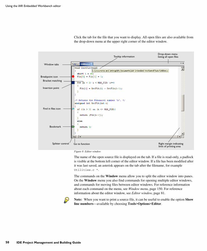
UIDEEW-1:1
50
Using the IAR Embedded Workbench editor
IDE Project Management and Building Guide
Click the tab for the file that you want to display. All open files are also available from the drop-down menu at the upper right corner of the editor window.
Figure 8: Editor window
The name of the open source file is displayed on the tab. If a file is read-only, a padlock is visible at the bottom left corner of the editor window. If a file has been modified after it was last saved, an asterisk appears on the tab after the filename, for example Utilities.c *.
The commands on the Window menu allow you to split the editor window into panes. On the Window menu you also find commands for opening multiple editor windows, and commands for moving files between editor windows. For reference information about each command on the menu, see Window menu, page 150. For reference information about the editor window, see Editor window, page 81.
Note: When you want to print a source file, it can be useful to enable the option Show line numbers—available by choosing Tools>Options>Editor.
Window tabs
Breakpoint icon
Bracket matching
Bookmark
Drop-down menulisting all open files
Splitter control Go to function
Tooltip information
Right margin indicating limit of printing area
Find in files icon
Insertion point

UIDEEW-1:1
Part 1. Project management and building
Editing
51
Accessing reference information for DLIB library functions
When you need to know the syntax for any library function, select the function name in the editor window and press F1. The library documentation for the selected function appears in a help window.
Using and customizing editor commands and shortcut keys
The Edit menu provides commands for editing and searching in editor windows, for instance, unlimited undo/redo (the Edit>Undo and Edit>Redo commands, respectively). You can also find some of these commands on the context menu that appears when you right-click in the editor window. For reference information about each command, see Edit menu, page 97.
There are also editor shortcut keys for:
● moving the insertion point
● scrolling text
● selecting text.
For detailed information about these shortcut keys, see Editor shortcut key summary, page 86.
To change the default shortcut key bindings, choose Tools>Options, and click the Key Bindings tab. For further details, see Key Bindings options, page 123.
Splitting the editor window into panes
You can split the editor window horizontally or vertically into multiple panes, to look at different parts of the same source file at once, or to move text between two different panes.
To split the window, double-click the appropriate splitter bar, or drag it to the middle of the window. Alternatively, you can split a window into panes using the Window>Split command.
To revert to a single pane, double-click the splitter control or drag it back to the end of the scroll bar.
Dragging and dropping of text
You can easily move text within an editor window or between editor windows. Select the text and drag it to the new location.

UIDEEW-1:1
52
Using the IAR Embedded Workbench editor
IDE Project Management and Building Guide
Syntax coloring
If the Tools>Options>Editor>Syntax highlighting option is enabled, the IAR Embedded Workbench editor automatically recognizes the syntax of:
● C and C++ keywords
● C and C++ comments
● Assembler directives and comments
● Preprocessor directives
● Strings.
The different parts of source code are displayed in different text styles.
To change these styles, choose Tools>Options, and use the Editor>Colors and Fonts options. For additional information, see Editor Colors and Fonts options, page 131.
In addition, you can define your own set of keywords that should be syntax-colored automatically:
1 In a text file, list all the keywords that you want to be automatically syntax-colored. Separate each keyword with either a space or a new line.
2 Choose Tools>Options and select Editor>Setup Files.
3 Select the Use Custom Keyword File option and specify your newly created text file. A browse button is available for your convenience.
4 Select Editor>Colors and Fonts and choose User Keyword from the Syntax Coloring list. Specify the font, color, and type style of your choice. For additional information, see Editor Colors and Fonts options, page 131.
5 In the editor window, type any of the keywords you listed in your keyword file; see how the keyword is syntax-colored according to your specification.
Automatic text indentation
The text editor can perform various kinds of indentation. For assembler source files and normal text files, the editor automatically indents a line to match the previous line. If you want to indent several lines, select the lines and press the Tab key. Press Shift+Tab to move a whole block of lines to the left.
For C/C++ source files, the editor indents lines according to the syntax of the C/C++ source code. This is performed whenever you:
● Press the Return key
● Type any of the special characters {, }, :, and #
● Have selected one or several lines, and choose the Edit>Auto Indent command.

UIDEEW-1:1
Part 1. Project management and building
Editing
53
To enable or disable the indentation:
1 Choose Tools>Options and select Editor.
2 Select or deselect the Auto indent option.
To customize the C/C++ automatic indentation, click the Configure button.
For additional information, see Configure Auto Indent dialog box, page 127.
Matching brackets and parentheses
When the insertion point is located next to a parenthesis, the matching parenthesis is highlighted with a light gray color:
Figure 9: Parenthesis matching in editor window
The highlight remains in place as long as the insertion point is located next to the parenthesis.
To select all text between the brackets surrounding the insertion point, choose Edit>Match Brackets. Every time you choose Match Brackets after that, the selection will increase to the next hierarchic pair of brackets.
Note: Both of these functions—automatic matching of corresponding parentheses and selection of text between brackets—apply to (), [], and {}.
Displaying status information
As you are editing, the status bar—available by choosing View>Status Bar— shows the current line and column number containing the insertion point, and the Caps Lock, Num Lock, and Overwrite status:
Figure 10: Editor window status bar
USING AND ADDING CODE TEMPLATES
Code templates is a method for conveniently inserting frequently used source code sequences, for example for loops and if statements. The code templates are defined in

UIDEEW-1:1
54
Using the IAR Embedded Workbench editor
IDE Project Management and Building Guide
a normal text file. By default, a few example templates are provided. In addition, you can easily add your own code templates.
Enabling code templates
By default, code templates are enabled. To enable and disable the use of code templates:
1 Choose Tools>Options.
2 Go to the Editor Setup Files page.
3 Select or deselect the Use Code Templates option.
4 In the text field, specify which template file you want to use; either the default file or one of your own template files. A browse button is available for your convenience.
Inserting a code template into your source code
To insert a code template into your source code, place the insertion point at the location where you want the template to be inserted, right-click, and choose Insert Template and the appropriate code template from the menu that appears.
Figure 11: Inserting a code template
If the code template you choose requires any type of field input, as in the for loop example which needs an end value and a count variable, an input dialog box appears.

UIDEEW-1:1
Part 1. Project management and building
Editing
55
Adding your own code templates
The source code templates are defined in a normal text file. The original template file CodeTemplates.txt is located in the common\config installation directory. The first time you use IAR Embedded Workbench, the original template file is copied to a directory for local settings, and this is the file that is used by default if code templates are enabled. To use your own template file, follow the procedure described in Enabling code templates, page 54.
To open the template file and define your own code templates, choose Edit>Code Templates>Edit Templates.
The syntax for defining templates is described in the default template file.
Selecting the correct language version of the code template file
When you start the IAR Embedded Workbench IDE for the very first time, you are asked to select a language version. This only applies if you are using an IDE that is available in other languages than English.
Selecting a language creates a corresponding language version of the default code template file in the Application Data\IAR Embedded Workbench subdirectory of the current Windows user (for example CodeTemplates.ENU.txt for English and CodeTemplates.JPN.txt for Japanese). The default code template file does not change automatically if you change the language version of the IDE afterwards.
To change the code template:
1 Choose Tools>Options>IDE Options>Editor>Setup Files.
2 Click the browse button of the Use Code Templates option and select a different template file.
If the code template file you want to select is not in the browsed directory, you must:
3 Delete the file name in the Use Code Templates text box.
4 Deselect the Use Code Templates option and click OK.
5 Restart the IAR Embedded Workbench IDE.
6 Then choose Tools>Options>IDE Options>Editor>Setup Files again.
The default code template file for the selected language version of the IDE should now be displayed in the Use Code Templates text box. Select the check box to enable the template.

UIDEEW-1:1
56
Using the IAR Embedded Workbench editor
IDE Project Management and Building Guide
NAVIGATING IN AND BETWEEN FILES
The editor provides several functions for easy navigation within the files and between files:
● Switching between source and header files
If the insertion point is located on an #include line, you can choose the Open "header.h" command from the context menu, which opens the header file in an editor window. You can also choose the command Open Header/Source File, which opens the header or source file that corresponds to the current file, or activates it if it is already open. This command is available if the insertion point is located on any line except an #include line.
● Function navigation
Click the Go to function button in the bottom left corner in an editor window to list all functions defined in the source file displayed in the window. You can then choose to go directly to one of the functions by double-clicking it in the list.
● Adding bookmarks
Use the Edit>Navigate>Toggle Bookmark command to add and remove bookmarks. To switch between the marked locations, choose Edit>Navigate>Go to Bookmark.
SEARCHING
There are several standard search functions available in the editor:
● Quick search text box
● Find dialog box
● Replace dialog box
● Find in files dialog box
● Incremental Search dialog box.
To use the Quick search text box on the toolbar:1 Type the text you want to search for and press Enter.
2 Press Esc to stop the search. This is a quick method for searching for text in the active editor window.
To use the Find, Replace, Find in Files, and Incremental Search functions:1 Before you use the search commands, choose Tools>Options>Editor and make sure
the Show bookmarks option is selected.
2 Choose the appropriate search command from the Edit menu. For reference information about each search function, see Edit menu, page 97.

UIDEEW-1:1
Part 1. Project management and building
Editing
57
3 To remove the blue flag icons that have appeared in the left-hand margin, right-click in the Find in Files window and choose Clear All from the context menu.
Customizing the editor environmentThe IDE editor can be configured on the IDE Options pages Editor and Editor Colors and Fonts. Choose Tools>Options to access the pages.
For details about these pages, see Tools menu, page 121.
USING AN EXTERNAL EDITOR
The External Editor options—available by choosing Tools>Options>Editor—let you specify an external editor of your choice.
Note: While debugging using C-SPY, C-SPY will not use the external editor for displaying the current debug state. Instead, the built-in editor will be used.
To specify an external editor of your choice, follow this procedure:
1 Select the option Use External Editor.
2 An external editor can be called in one of two ways, using the Type drop-down menu.
Command Line calls the external editor by passing command line parameters.
DDE calls the external editor by using DDE (Windows Dynamic Data Exchange).
3 If you use the command line, specify the command line to pass to the editor, that is, the name of the editor and its path, for instance:
C:\Windows\NOTEPAD.EXE.

UIDEEW-1:1
58
Customizing the editor environment
IDE Project Management and Building Guide
To send an argument to the external editor, type the argument in the Arguments field. For example, type $FILE_PATH$ to start the editor with the active file (in editor, project, or Messages window).
Figure 12: Specifying an external command line editor
Note: Options for Register Filter and Terminal I/O are only available when the C-SPY debugger is running.
4 If you use DDE, specify the editor’s DDE service name in the Service field. In the Command field, specify a sequence of command strings to send to the editor.
The service name and command strings depend on the external editor that you are using. Refer to the user documentation of your external editor to find the appropriate settings.
The command strings should be entered as:
DDE-Topic CommandString1DDE-Topic CommandString2

UIDEEW-1:1
Part 1. Project management and building
Editing
59
as in this example, which applies to Codewright®:
Figure 13: External editor DDE settings
The command strings used in this example will open the external editor with a dedicated file activated. The cursor will be located on the current line as defined in the context from where the file is open, for instance when searching for a string in a file, or when double-clicking an error message in the Message window.
5 Click OK.
When you double-click a file in the Workspace window, the file is opened by the external editor.
Variables can be used in the arguments. For more information about the argument variables that are available, see Argument variables, page 117.

UIDEEW-1:1
60
Customizing the editor environment
IDE Project Management and Building Guide

UIDEEW-1:1
61
Part 2. Reference informationThis part of the IDE Project Management and Building Guide contains these chapters:
● Installed files
● IAR Embedded Workbench IDE reference.

UIDEEW-1:1
62

UIDEEW-1:1
Part 1. Project management and building 63
Installed filesThis chapter describes which directories that are created during installation and which file types that are used.
Directory structure The installation procedure creates several directories to contain the various types of files used with the IAR Systems development tools. The following sections give a description of the files contained by default in each directory.
ROOT DIRECTORY
The root directory created by the default installation procedure is the x:\Program Files\IAR Systems\Embedded Workbench 6.n\ directory where x is the drive where Microsoft Windows is installed and 6.n is the version number of the IDE.
In the root directory, there are two subdirectories—common and one named after the processor you are using. The latter directory will hereafter be referred to as cpuname.
THE CPUNAME DIRECTORY
The cpuname directory contains all product-specific subdirectories.
Directory Description
cpuname\bin The cpuname\bin subdirectory contains executable files for target-specific components, such as the compiler, the assembler, the linker and the library tools, and the C-SPY® drivers.
cpuname\config The cpuname\config subdirectory contains files used for configuring the development environment and projects, for example: • Linker configuration files (*.xcl for XLINK)(*.icf for ILINK)• Special function register description files (*.sfr)• C-SPY device description files (*.ddf)• Device selection files (*.ixx, *.menu)• Flash loader applications for various devices (*.dxx), depends on your product package• Syntax coloring configuration files (*.cfg)• Project templates for both application and library projects (*.ewp), and for the library projects, the corresponding library configuration files.
Table 5: The CPUNAME directory

UIDEEW-1:1
64
Directory structure
IDE Project Management and Building Guide
THE COMMON DIRECTORY
The common directory contains subdirectories for components shared by all IAR Embedded Workbench products.
cpuname\doc The cpuname\doc subdirectory contains release notes with recent additional information about the CPUNAME tools. We recommend that you read all of these files. The directory also contains online versions in hypertext PDF format of this user guide, and of the CPUNAME reference guides, as well as online help files (*.chm).
cpuname\drivers The cpuname\drivers subdirectory contains low-level device drivers, typically USB drivers required by the C-SPY drivers.
cpuname\examplesThe cpuname\examples subdirectory contains files related to example projects, which can be opened from the Information Center.
cpuname\inc The cpuname\inc subdirectory holds include files, such as the header files for the standard C or C++ library. There are also specific header files that define special function registers (SFRs); these files are used by both the compiler and the assembler.
cpuname\lib The cpuname\lib subdirectory holds prebuilt libraries and the corresponding library configuration files, used by the compiler.
cpuname\plugins The cpuname\plugins subdirectory contains executable files and description files for components that can be loaded as plugin modules.
cpuname\src The cpuname\src subdirectory holds source files for some configurable library functions. This directory also holds the library source code and the source code for ELF utilities (the latter only for the ILINK linker).If your product package includes the XLINK linker, the directory also contains source files for components common to all IAR Embedded Workbench products, such as a sample reader of the IAR XLINK Linker output format SIMPLE.
cpuname\tutor The cpuname\tutor subdirectory contains the files used for the tutorials in this guide.
Directory Description
common\bin The common\bin subdirectory contains executable files for components common to all IAR Embedded Workbench products, such as the editor and the graphical user interface components. The executable file for the IDE is also located here.
Table 6: The common directory
Directory Description
Table 5: The CPUNAME directory (Continued)

UIDEEW-1:1
Part 1. Project management and building
Installed files
65
THE INSTALL-INFO DIRECTORY
The install-info directory contains metadata (version number, name, etc.) about the installed product components. Do not modify these files.
File typesThe versions of the IAR Systems development tools use the following default filename extensions to identify the produced files and other recognized file types:
common\config The common\config subdirectory contains files used by the IDE for settings in the development environment.
common\doc The common\doc subdirectory contains release notes with recent additional information about the components common to all IAR Embedded Workbench products. We recommend that you read these files. The directory also contains documentation related to installation and licensing, and getting started using IAR Embedded Workbench.
common\plugins The common\plugins subdirectory contains executable files and description files for components that can be loaded as plugin modules, for example modules for Code coverage and Profiling.
Directory Description
Table 6: The common directory (Continued)
Ext. Type of file Output from Input to
axx / out Target application XLINK/ILINK EPROM, C-SPY, etc.
asm Assembler source code Text editor Assembler
bat Windows command batch file C-SPY Windows
c C source code Text editor Compiler
cfg Syntax coloring configuration Text editor IDE
chm Online help system file -- IDE
cpp C++ source code Text editor Compiler
dxx / out Target application with debug information XLINK/ILINK C-SPY and other symbolic debuggers
dat Macros for formatting of STL containers IDE IDE
dbg Target application with debug information XLINK C-SPY and other symbolic debuggers
dbgt Debugger desktop settings C-SPY C-SPY
ddf Device description file Text editor C-SPY
Table 7: File types

UIDEEW-1:1
66
File types
IDE Project Management and Building Guide
dep Dependency information IDE IDE
dni Debugger initialization file C-SPY C-SPY
ewd Project settings for C-SPY IDE IDE
ewp IAR Embedded Workbench project (current version)
IDE IDE
ewplugin IDE description file for plugin modules -- IDE
eww Workspace file IDE IDE
fmt Formatting information for the Locals and Watch windows
IDE IDE
h C/C++ or assembler header source Text editor Compiler or assembler #include
helpfiles Help menu configuration file Text editor IDE
html, htm HTML document Text editor IDE
i Preprocessed source Compiler Compiler
ixx Device selection file Text editor IDE
icf Linker configuration file Text editor ILINK linker
inc Assembler header source Text editor Assembler #include
ini Project configuration IDE –
log Log information IDE –
lst List output Compiler and assembler
–
mac C-SPY macro definition Text editor C-SPY
map List output XLINK –
menu Device selection file Text editor IDE
pbd Source browse information IDE IDE
pbi Source browse information IDE IDE
pew IAR Embedded Workbench project (old project format)
IDE IDE
prj IAR Embedded Workbench project (old project format)
IDE IDE
rxx / o Object module Compiler and assembler
XLINK, XAR, XLIB, or ILINK
Ext. Type of file Output from Input to
Table 7: File types (Continued)

UIDEEW-1:1
Part 1. Project management and building
Installed files
67
Note: The notation xx denotes two digits, which form an identifier for the processor you are using (for XLINK products).
When you run the IDE, some files are created and located in dedicated directories under your project directory, by default $PROJ_DIR$\Debug, $PROJ_DIR$\Release, $PROJ_DIR$\settings, and the file *.dep under the installation directory. None of these directories or files affect the execution of the IDE, which means you can safely remove them if required.
FILES WITH NON-DEFAULT FILENAME EXTENSIONS
In the IDE you can increase the number of recognized filename extensions using the Filename Extensions dialog box, available from the Tools menu. You can also connect your filename extension to a specific tool in the toolchain. See Filename Extensions dialog box, page 146.
To override the default filename extension from the command line, include an explicit extension when you specify a filename.
Note: If you run the tools from the command line, the XLINK listings (map files) will, by default, have the extension lst, which might overwrite the list file generated by the compiler. Therefore, we recommend that you name XLINK map files explicitly, for example project1.map.
rxx / a Library XAR, XLIBiarchive
XLINK, XLIBILINK, iarchive
sxx / s Assembler source code Text editor Assembler
sfr Special function register definitions Text editor C-SPY
vsp visualSTATE project files IAR visualSTATE Designer
IAR visualSTATE Designer and IAR Embedded Workbench IDE
wsdt Workspace desktop settings IDE IDE
xcl Extended command line Text editor Assembler, compiler, linker
xlb Extended librarian batch command Text editor XLIB
Ext. Type of file Output from Input to
Table 7: File types (Continued)

UIDEEW-1:1
68
File types
IDE Project Management and Building Guide

UIDEEW-1:1
Part 2. Reference information 69
IAR Embedded Workbench IDE referenceThis chapter contains reference information about the windows, menus, menu commands, and the corresponding components that are found in the IDE. This chapter contains the following sections:
● Windows, page 69
● Menus, page 94.
The IDE is a modular application. Which menus are available depends on which components are installed.
WindowsThe available windows are:
● IAR Embedded Workbench IDE window
● Workspace window
● Editor window
● Source Browser window
● Message windows.
In addition, a set of C-SPY®-specific windows becomes available when you start the debugger. For reference information about these windows, see the C-SPY® Debugging Guide.

UIDEEW-1:1
70
Windows
IDE Project Management and Building Guide
IAR Embedded Workbench IDE windowThe main window of the IDE is displayed when you launch the IDE.
Figure 14: IAR Embedded Workbench IDE window
The figure shows the window and its various components. The window might look different depending on which plugin modules you are using.
Menu bar
The menu bar contains:
ToolbarMenu bar
Workspace window
Message windows
Editorwindow
Status bar
File Commands for opening source and project files, saving and printing, and exiting from the IDE.
Edit Commands for editing and searching in editor windows and for enabling and disabling breakpoints in C-SPY.

UIDEEW-1:1
Part 2. Reference information
IAR Embedded Workbench IDE reference
71
For reference information about each menu, see Menus, page 94.
Toolbar
The IDE toolbar—available from the View menu—provides buttons for the most useful commands on the IDE menus, and a text box for typing a string to do a quick search.
For a description of any button, point to it with the mouse button. When a command is not available, the corresponding toolbar button is dimmed, and you will not be able to click it.
This figure shows the menu commands corresponding to each of the toolbar buttons:
Figure 15: IDE toolbar
Note: When you start C-SPY, the Download and Debug button will change to a Make and Debug button and the Debug without Downloading will change to a Restart Debugger button.
Status bar
The status bar at the bottom of the window displays the number of errors and warnings generated during a build, the position of the insertion point in the editor window, and the state of the modifier keys. The status bar can be enabled from the View menu.
View Commands for opening windows and controlling which toolbars to display.
Project Commands for adding files to a project, creating groups, and running the IAR Systems tools on the current project.
Tools User-configurable menu to which you can add tools for use with the IDE.
Window Commands for manipulating the IDE windows and changing their arrangement on the screen.
Help Commands that provide help about the IDE.
New Document
Save
Cut
Paste
Quick Search text box
Find Next
Replace
Open
Copy
Redo
Undo
FindStop Build
Make
Download and DebugFind Previous
Save All
Toggle Bookmark
Go to Bookmark
Navigate Backward
Navigate Forward ToggleBreakpoint
Compile
Go To
Debug without Downloading

UIDEEW-1:1
72
Windows
IDE Project Management and Building Guide
As you are editing, the status bar shows the current line and column number containing the insertion point, and the Caps Lock, Num Lock, and Overwrite status. If your product package is available in more languages than English, a flag in the corner shows the language version you are using. Click the flag to change the language the next time you launch the IDE.
Figure 16: IAR Embedded Workbench IDE window status bar
Workspace windowThe Workspace window is available from the View menu.
Figure 17: Workspace window
Use the Workspace window to access your projects and files during the application development.
Drop-down list
At the top of the window there is a drop-down list where you can choose a build configuration to display in the window for a specific project.
Configurationdrop-down menu
Tabs for choosing workspace display
Indicates that the file willbe rebuilt the next time
the project is built
Column containingsource code control
status information
Column containingstatus information
about option overrides
Project icon (currently indicates multi-file compilation
Column containing build status information

UIDEEW-1:1
Part 2. Reference information
IAR Embedded Workbench IDE reference
73
The display area
This area contains four columns.
The Files column displays the name of the current workspace and a tree representation of the projects, groups and files included in the workspace. One or more of these icons are displayed:
The column that contains status information about option overrides can have one of three icons for each level in the project:
Workspace
Project
Project with multi-file compilation
Group of files
Group excluded from the build
Group of files, part of multi-file compilation
Group of files, part of multi-file compilation, but excluded from the build
Object file or library
Assembler source file
C source file
C++ source file
Source file excluded from the build
Header file
Text file
HTML text file
Control file, for example the linker configuration file
IDE internal file
Other file
Blank There are no settings/overrides for this file/group.
Black check mark There are local settings/overrides for this file/group.

UIDEEW-1:1
74
Windows
IDE Project Management and Building Guide
The column that contains build status information can have one of three icons for each file in the project:
For details about the various source code control icons, see Source code control states, page 77.
Use the tabs at the bottom of the window to choose which project to display. Alternatively, you can choose to display an overview of the entire workspace.
For more information about project management and using the Workspace window, see the chapter Managing projects.
Context menu
This context menu is available:
Figure 18: Workspace window context menu
Red check mark There are local settings/overrides for this file/group, but they are either identical to the inherited settings or they are ignored because you use multi-file compilation, which means that the overrides are not needed.
Blank The file will not be rebuilt next time the project is built.
Red star The file will be rebuilt next time the project is built.
Gearwheel The file is being rebuilt.

UIDEEW-1:1
Part 2. Reference information
IAR Embedded Workbench IDE reference
75
These commands are available:
Options Displays a dialog box where you can set options for each build tool, for the selected item in the Workspace window. You can set options for the entire project, for a group of files, for on an individual file. See Setting options, page 41.
Make Brings the current target up to date by compiling, assembling, and linking only the files that have changed since the last build.
Compile Compiles or assembles the currently active file as appropriate. You can choose the file either by selecting it in the Workspace window, or by selecting the editor window containing the file you want to compile.
Rebuild All Recompiles and relinks all files in the selected build configuration.
Clean Deletes intermediate files.
Stop Build Stops the current build operation.
Add>Add Files Displays a dialog box where you can add files to the project.
Add>Add filename Adds the indicated file to the project. This command is only available if there is an open file in the editor.
Add>Add Group Displays the Add Group dialog box where you can add new groups to the project. For more information about groups, see Groups, page 34.
Remove Removes selected items from the Workspace window.
Rename Displays the Rename Group dialog box where you can rename a group. For more information about groups, see Groups, page 34.
Source Code Control Opens a submenu with commands for source code control, see Source Code Control menu, page 76.
File Properties Displays a standard File Properties dialog box for the selected file.
Set as Active Sets the selected project in the overview display to be the active project. It is the active project that will be built when the Make command is executed.

UIDEEW-1:1
76
Windows
IDE Project Management and Building Guide
Source Code Control menu
The Source Code Control menu is available from the Project menu and from the context menu in the Workspace window.
Figure 19: Source Code Control menu
These commands are available:
Check In Displays the Check In Files dialog box where you can check in the selected files; see Check In Files dialog box, page 79. Any changes you have made in the files will be stored in the archive. This command is enabled when currently checked-out files are selected in the Workspace window.
Check Out Checks out the selected file or files. Depending on the SCC (Source Code Control) system you are using, a dialog box might appear; see Check Out Files dialog box, page 80. This means you get a local copy of the file(s), which you can edit. This command is enabled when currently checked-in files are selected in the Workspace window.
Undo Checkout Reverts the selected files to the latest archived version; the files are no longer checked out. Any changes you have made to the files will be lost. This command is enabled when currently checked-out files are selected in the Workspace window.
Get Latest Version Replaces the selected files with the latest archived version.
Compare Displays—in an SCC-specific window—the differences between the local version and the most recent archived version.
History Displays SCC-specific information about the revision history of the selected file.

UIDEEW-1:1
Part 2. Reference information
IAR Embedded Workbench IDE reference
77
For more information about interacting with an external source code control system, see Source code control, page 39.
Source code control states
Each source code-controlled file can be in one of several states.
Note: The source code control in IAR Embedded Workbench depends on the information provided by the SCC system. If the SCC system provides incorrect or
Properties Displays information available in the SCC system for the selected file.
Refresh Updates the SCC display status for all the files that are part of the project. This command is always enabled for all projects under SCC.
Connect Project to SCC Project
Displays a dialog box, which originates from the SCC client application, to let you create a connection between the selected IAR Embedded Workbench project and an SCC project; the IAR Embedded Workbench project will then be an SCC-controlled project. After creating this connection, a special column that contains status information will appear in the Workspace window.
Disconnect Project from SCC Project
Removes the connection between the selected IAR Embedded Workbench project and an SCC project; your project will no longer be a SCC-controlled project. The column in the Workspace window that contains SCC status information will no longer be visible for that project.
(blank) Checked out to you. The file is editable.
(checkmark) Checked out to you. The file is editable and you have modified the file.
(gray padlock) Checked in. In many SCC systems this means that the file is write-protected.
(gray padlock) Checked in. A new version is available in the archive.
(red padlock) Checked out exclusively to another user. In many SCC systems this means that you cannot check out the file.
(red padlock) Checked out exclusively to another user. A new version is available in the archive. In many SCC systems this means that you cannot check out the file.

UIDEEW-1:1
78
Windows
IDE Project Management and Building Guide
incomplete information about the states, IAR Embedded Workbench might display incorrect symbols.
Select Source Code Control Provider dialog boxThe Select Source Code Control Provider dialog box is displayed if several SCC systems from different vendors are available.
Figure 20: Select Source Code Control Provider dialog box
Use this dialog box to choose the SCC system you want to use.

UIDEEW-1:1
Part 2. Reference information
IAR Embedded Workbench IDE reference
79
Check In Files dialog boxThe Check In Files dialog box is available by choosing the Project>Source Code Control>Check In command, alternatively available from the Workspace window context menu.
Figure 21: Check In Files dialog box
Comment
Specify a comment—typically a description of your changes—that will be stored in the archive together with the file revision. This text box is only enabled if the SCC system supports adding comments at check in.
Keep checked out
Specifies that the files will continue to be checked out after they have been checked in. Typically, this is useful if you want to make your modifications available to other members in your project team, without stopping your own work with the file.
Advanced
Displays a dialog box, originating from the SCC client application, that contains advanced options. This button is only available if the SCC system supports setting advanced options at check in.
Files
Lists the files that will be checked in. The list will contain all files that were selected in the Workspace window when the Check In Files dialog box was opened.

UIDEEW-1:1
80
Windows
IDE Project Management and Building Guide
Check Out Files dialog boxThe Check Out Files dialog box is available by choosing the Project>Source Code Control>Check Out command, alternatively available from the Workspace window context menu. However, this dialog box is only available if the SCC system supports adding comments at check out or advanced options.
Figure 22: Check Out Files dialog box
Comment
Specify a comment—typically the reason why the file is checked out—that will be placed in the archive together with the file revision. This text box is only enabled if the SCC system supports the adding of comments at check out.
Advanced
Displays a dialog box, originating from the SCC client application, that contains advanced options. This button is only available if the SCC system supports setting advanced options at check out.
Files
Lists files that will be checked out. The list will contain all files that were selected in the Workspace window when the Check Out Files dialog box was opened.

UIDEEW-1:1
Part 2. Reference information
IAR Embedded Workbench IDE reference
81
Editor windowThe editor window is opened when you open or create a text file in the IDE.
Figure 23: Editor window
Source code files and HTML files are displayed in editor windows. From an open HTML document, hyperlinks to HTML files work like in normal web browsing. A link to an eww workspace file opens the workspace in the IDE, and closes any currently open workspace and the open HTML document.
You can have one or several editor windows open at the same time. On the Window menu you find commands for opening multiple editor windows, and commands for moving files between the editor windows.
The editor window is always docked, and its size and position depend on other currently open windows. If a file is read-only, a padlock icon is visible at the bottom left corner of the editor window.
For more information about using the editor, see Edit menu, page 97 and the chapter Editing.
Window tabs
Breakpoint icon
Bracket matching
Bookmark
Drop-down menulisting all open files
Splitter control Go to function
Tooltip information
Right margin indicating limit of printing area
Find in files icon
Insertion point

UIDEEW-1:1
82
Windows
IDE Project Management and Building Guide
Source file paths
The IDE supports relative source file paths to a certain degree.
If a source file is located in the project file directory or in any subdirectory of the project file directory, the IDE will use a path relative to the project file when accessing the source file.
Window tabs
The name of the open file is displayed on the tab. If a file has been modified after it was last saved, an asterisk appears after the filename on the tab, for example Utilities.c *.
A context menu appears if you right-click on a tab in the editor window.
Figure 24: Editor window tab context menu
These commands are available:
All open files are available from the drop-down menu in the upper right corner of the editor window.
Splitter controls
Use the Window>Split command—or the Splitter controls—to split the editor window horizontally or vertically into multiple panes.
Save file Saves the file.
Close Closes the file.
File Properties Displays a standard file properties dialog box.

UIDEEW-1:1
Part 2. Reference information
IAR Embedded Workbench IDE reference
83
Go to function
Click the Go to function button in the bottom left-hand corner of the editor window to list all functions of the C or C++ editor window.
Figure 25: Go to Function window
Double-click the function that you want to show in the editor window.
Context menu
This context menu is available:
Figure 26: Editor window context menu
The contents of this menu depends on whether the debugger is started or not, and on the C-SPY driver you are using. Typically, additional breakpoint types might be available on this menu. For information about available breakpoints, see the C-SPY® Debugging Guide.

UIDEEW-1:1
84
Windows
IDE Project Management and Building Guide
These commands are available:
Cut, Copy, Paste Standard window commands.
Complete Attempts to complete the word you have begun to type, basing the guess on the contents of the rest of the editor document.
Match Brackets Selects all text between the brackets immediately surrounding the insertion point, increases the selection to the next hierarchic pair of brackets, or beeps if there is no higher bracket hierarchy.
Insert Template Displays a list in the editor window from which you can choose a code template to be inserted at the location of the insertion point. If the code template you choose requires any field input, the Template dialog box appears; for information about this dialog box, see Template dialog box, page 106. For information about using code templates, see Using and adding code templates, page 53.
Open "header.h" Opens the header file header.h in an editor window. This menu command is only available if the insertion point is located on an #include line when you open the context menu.
Open Header/Source File
Jumps from the current file to the corresponding header or source file. If the destination file is not open when performing the command, the file will first be opened. This menu command is only available if the insertion point is located on any line except an #include line when you open the context menu. This command is also available from the File>Open menu.
Go to definition of symbol
Shows the declaration of the symbol where the insertion point is placed.
Check In
Check Out
Undo Checkout
Commands for source code control; for more details, see Source Code Control menu, page 76. These menu commands are only available if the current source file in the editor window is SCC-controlled. The file must also be a member of the current project.
Toggle Breakpoint (Code)
Toggles a code breakpoint at the statement or instruction containing or close to the cursor in the source window. For information about code breakpoints, see the C-SPY® Debugging Guide.

UIDEEW-1:1
Part 2. Reference information
IAR Embedded Workbench IDE reference
85
Toggle Breakpoint(Log)
Toggles a log breakpoint at the statement or instruction containing or close to the cursor in the source window. For information about log breakpoints, see the C-SPY® Debugging Guide.
Toggle Breakpoint (Trace Start)
Toggles a Trace Start breakpoint. When the breakpoint is triggered, trace data collection starts. For information about Trace Start breakpoints, see the C-SPY® Debugging Guide. Note that this menu command is only available if the C-SPY driver you are using supports trace.
Toggle Breakpoint (Trace Stop)
Toggles a Trace Stop breakpoint. When the breakpoint is triggered, trace data collection stops. For information about Trace Stop breakpoints, see the C-SPY® Debugging Guide. Note that this menu command is only available if the C-SPY driver you are using supports trace.
Enable/disableBreakpoint
Toggles a breakpoint between being disabled, but not actually removed—making it available for future use—and being enabled again.
Set Data Breakpointfor 'variable'
Toggles a data breakpoint on variables with static storage duration. Requires support in the C-SPY driver you are using.
Edit Breakpoint Displays the Edit Breakpoint dialog box to let you edit the breakpoint available on the source code line where the insertion point is located. If there is more than one breakpoint on the line, a submenu is displayed that lists all available breakpoints on that line.
Set Next Statement Sets the PC directly to the selected statement or instruction without executing any code. Use this menu command with care. This menu command is only available when you are using the debugger.
Quick Watch Opens the Quick Watch window, see the C-SPY® Debugging Guide. This menu command is only available when you are using the debugger.
Add to Watch Adds the selected symbol to the Watch window. This menu command is only available when you are using the debugger.
Move to PC Moves the insertion point to the current PC position in the editor window. This menu command is only available when you are using the debugger.

UIDEEW-1:1
86
Windows
IDE Project Management and Building Guide
Editor shortcut key summary
The following tables summarize the editor’s shortcut keys.
Moving the insertion point:
Scrolling text:
Selecting text:
Run to Cursor Executes from the current statement or instruction up to a selected statement or instruction. This menu command is only available when you are using the debugger.
Options Displays the IDE Options dialog box, see Tools menu, page 121.
To move the insertion point Press
One character left Arrow left
One character right Arrow right
One word left Ctrl+Arrow left
One word right Ctrl+Arrow right
One line up Arrow up
One line down Arrow down
To the start of the line Home
To the end of the line End
To the first line in the file Ctrl+Home
To the last line in the file Ctrl+End
Table 8: Editor keyboard commands for insertion point navigation
To scroll Press
Up one line Ctrl+Arrow up
Down one line Ctrl+Arrow down
Up one page Page Up
Down one page Page Down
Table 9: Editor keyboard commands for scrolling
To select Press
The character to the left Shift+Arrow left
The character to the right Shift+Arrow right
Table 10: Editor keyboard commands for selecting text

UIDEEW-1:1
Part 2. Reference information
IAR Embedded Workbench IDE reference
87
Source Browser windowThe Source Browser window is available from the View menu.
Figure 27: Source Browser window
The Source Browser window displays an hierarchical view in alphabetical order of all symbols defined in the active build configuration. This means that source browse information is available for symbols in source files and include files part of that configuration. Source browse information is not available for symbols in linked libraries. The window consists of two separate display areas.
One word to the left Shift+Ctrl+Arrow left
One word to the right Shift+Ctrl+Arrow right
To the same position on the previous line Shift+Arrow up
To the same position on the next line Shift+Arrow down
To the start of the line Shift+Home
To the end of the line Shift+End
One screen up Shift+Page Up
One screen down Shift+Page Down
To the beginning of the file Shift+Ctrl+Home
To the end of the file Shift+Ctrl+End
To select Press
Table 10: Editor keyboard commands for selecting text (Continued)

UIDEEW-1:1
88
Windows
IDE Project Management and Building Guide
For information about how to use the Source Browser window, see Displaying browse information, page 38.
The upper display area
The upper display area contains two columns:
If you click in the window header, you can sort the symbols either by name or by symbol type.
In the upper display area you can also access a context menu; see Context menu, page 89.
The lower display area
For a symbol selected in the upper display area, the lower area displays its properties:
Icons used for the symbol types
These are the icons used:
An icon that corresponds to the Symbol type classification, see Icons used for the symbol types, page 88.
Name The names of global symbols and functions defined in the project.
Full name Displays the unique name of each element, for instance classname::membername.
Symbol type Displays the symbol type for each element, see Icons used for the symbol types, page 88.
Filename Specifies the path to the file in which the element is defined.
Base class
Class
Configuration
Enumeration
Enumeration constant
(Yellow rhomb) Field of a struct
(Purple rhomb) Function

UIDEEW-1:1
Part 2. Reference information
IAR Embedded Workbench IDE reference
89
Context menu
This context menu is available in the upper display area:
Figure 28: Source Browser window context menu
These commands are available on the context menu:
Macro
Namespace
Template class
Template function
Type definition
Union
(Yellow rhomb) Variable
Go to Definition The editor window will display the definition of the selected item.
Move to Parent If the selected element is a member of a class, struct, union, enumeration, or namespace, this menu command can be used for moving to its enclosing element.
All Symbols Type filter; displays all global symbols and functions defined in the project.
All Functions & Variables
Type filter; displays all functions and variables defined in the project.
Non-Member Functions & Variables
Type filter; displays all functions and variables that are not members of a class.
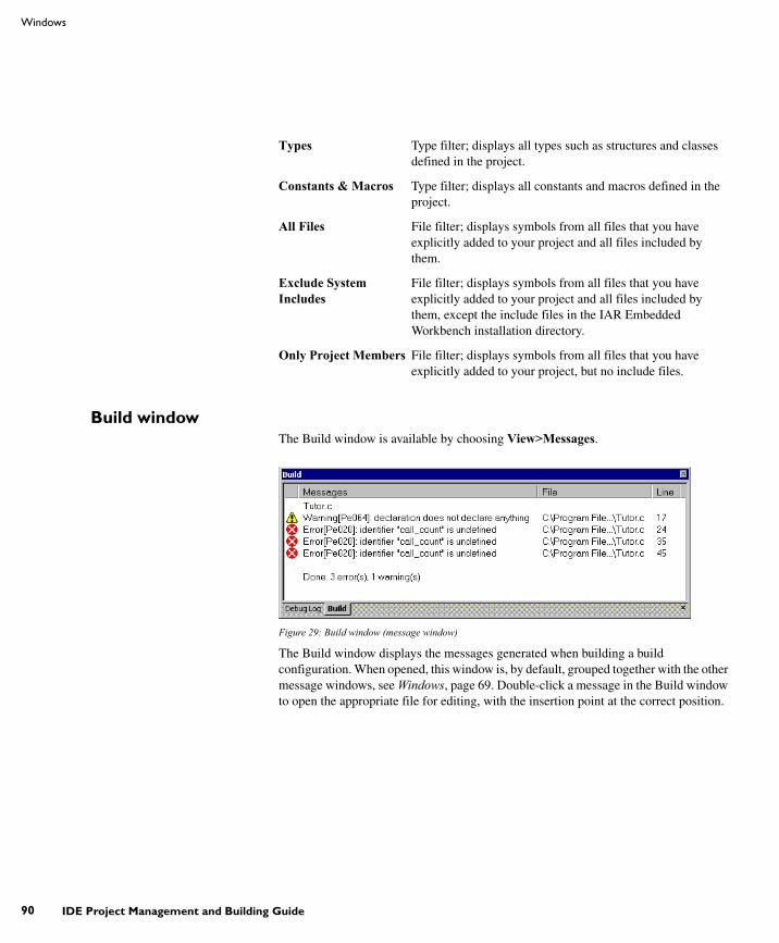
UIDEEW-1:1
90
Windows
IDE Project Management and Building Guide
Build windowThe Build window is available by choosing View>Messages.
Figure 29: Build window (message window)
The Build window displays the messages generated when building a build configuration. When opened, this window is, by default, grouped together with the other message windows, see Windows, page 69. Double-click a message in the Build window to open the appropriate file for editing, with the insertion point at the correct position.
Types Type filter; displays all types such as structures and classes defined in the project.
Constants & Macros Type filter; displays all constants and macros defined in the project.
All Files File filter; displays symbols from all files that you have explicitly added to your project and all files included by them.
Exclude System Includes
File filter; displays symbols from all files that you have explicitly added to your project and all files included by them, except the include files in the IAR Embedded Workbench installation directory.
Only Project Members File filter; displays symbols from all files that you have explicitly added to your project, but no include files.

UIDEEW-1:1
Part 2. Reference information
IAR Embedded Workbench IDE reference
91
Context menu
This context menu is available:
Figure 30: Build window context menu
These commands are available:
Find in Files windowThe Find in Files window is available by choosing View>Messages.
Figure 31: Find in Files window (message window)
The Find in Files window displays the output from the Edit>Find and Replace>Find in Files command. When opened, this window is, by default, grouped together with the other message windows, see Windows, page 69.
Double-click an entry in the window to open the appropriate file with the insertion point positioned at the correct location. That source location is highlighted with a blue flag icon.
Copy Copies the contents of the window.
Select All Selects the contents of the window.
Clear All Deletes the contents of the window.
Options Opens the Messages page of the IDE options dialog box. On this page you can set options related to messages; see Messages options, page 132.

UIDEEW-1:1
92
Windows
IDE Project Management and Building Guide
Context menu
This context menu is available:
Figure 32: Find in Files window context menu
These commands are available:
Tool Output windowThe Tool Output window is available by choosing View>Messages>Tool Output.
Figure 33: Tool Output window (message window)
The Tool Output window displays any messages output by user-defined tools in the Tools menu, provided that you have selected the option Redirect to Output Window in the Configure Tools dialog box; see Configure Tools dialog box, page 143. When opened, this window is, by default, grouped together with the other message windows, see Windows, page 69.
Copy Copies the contents of the window.
Select All Selects the contents of the window.
Clear All Deletes the contents of the window and any blue flag icons in the left-side margin of the editor window.

UIDEEW-1:1
Part 2. Reference information
IAR Embedded Workbench IDE reference
93
Context menu
This context menu is available:
Figure 34: Tool Output window context menu
These commands are available:
Debug Log windowThe Debug Log window is available by choosing View>Messages>Debug Log.
Figure 35: Debug Log window (message window)
The Debug Log window displays debugger output, such as diagnostic messages and trace information. When opened, this window is, by default, grouped together with the other message windows, see Windows, page 69.
Double-click any rows in one of the following formats to display the corresponding source code in the editor window:
<path> (<row>):<message><path> (<row>,<column>):<message>
Copy Copies the contents of the window.
Select All Selects the contents of the window.
Clear All Deletes the contents of the window.

UIDEEW-1:1
94
Menus
IDE Project Management and Building Guide
Context menu
This context menu is available:
Figure 36: Debug Log window context menu
These commands are available:
MenusThe available menus are:
● File menu
● Edit menu
● View menu
● Project menu
● Tools menu
● Window menu
● Help menu.
In addition, a set of C-SPY-specific menus become available when you start the debugger. For reference information about these menus, see the C-SPY® Debugging Guide.
File menuThe File menu provides commands for opening workspaces and source files, saving and printing, and exiting from the IDE.
Copy Copies the contents of the window.
Select All Selects the contents of the window.
Clear All Deletes the contents of the window.

UIDEEW-1:1
Part 2. Reference information
IAR Embedded Workbench IDE reference
95
The menu also includes a numbered list of the most recently opened files and workspaces. To open one of them, choose it from the menu.
Figure 37: File menu
These commands are available:
NewCtrl+N
Displays a submenu with commands for creating a new workspace, or a new text file.
Open>FileCtrl+O
Displays a submenu from which you can select a text file or an HTML document to open. See Editor window, page 81.
Open>Workspace Displays a submenu from which you can select a workspace file to open. Before a new workspace is opened you will be prompted to save and close any currently open workspaces.
Open>Header/Source FileCtrl+Shift+H
Opens the header file or source file that corresponds to the current file, and jumps from the current file to the newly opened file. This command is also available from the context menu available from the editor window.
Close Closes the active window. You will be given the opportunity to save any files that have been modified before closing.

UIDEEW-1:1
96
Menus
IDE Project Management and Building Guide
Open Workspace Displays a dialog box where you can open a workspace file.
You will be given the opportunity to save and close any currently open workspace file that has been modified before opening a new workspace.
Save Workspace Saves the current workspace file.
Close Workspace Closes the current workspace file.
SaveCtrl+S
Saves the current text file or workspace file.
Save As Displays a dialog box where you can save the current file with a new name.
Save All Saves all open text documents and workspace files.
Page Setup Displays a dialog box where you can set printer options.
PrintCtrl+P
Displays a dialog box where you can print a text document.
Recent Files Displays a submenu where you can quickly open the most recently opened text documents.
Recent Workspaces Displays a submenu where you can quickly open the most recently opened workspace files.
Exit Exits from the IDE. You will be asked whether to save any changes to text files before closing them. Changes to the project are saved automatically.

UIDEEW-1:1
Part 2. Reference information
IAR Embedded Workbench IDE reference
97
Edit menuThe Edit menu provides commands for editing and searching.
Figure 38: Edit menu
These commands are available:
UndoCtrl+Z
Undoes the last edit made to the current editor window.
RedoCtrl+Y
Redoes the last Undo in the current editor window.
You can undo and redo an unlimited number of edits independently in each editor window.
CutCtrl+X
The standard Windows command for cutting text in editor windows and text boxes.
CopyCtrl+C
The standard Windows command for copying text in editor windows and text boxes.
PasteCtrl+V
The standard Windows command for pasting text in editor windows and text boxes.
Paste Special Provides you with a choice of the most recent contents of the clipboard to choose from when pasting in editor documents.
UIDEEW-1:1
98
Menus
IDE Project Management and Building Guide
Select AllCtrl+A
Selects all text in the active editor window.
Find and Replace>FindCtrl+F
Displays the Find dialog box where you can search for text within the current editor window; see Find dialog box, page 101. Note that if the insertion point is located in the Memory window when you choose the Find command, the dialog box will contain a different set of options than otherwise. If the insertion point is located in the Trace window when you choose the Find command, the Find in Trace dialog box is opened; the contents of this dialog box depend on the C-SPY driver you are using, see the C-SPY® Debugging Guide for more information.
Find and Replace>Find NextF3
Finds the next occurrence of the specified string.
Find and Replace>Find PreviousShift+F3
Finds the previous occurrence of the specified string.
Find and Replace>Find Next (Selected)Ctrl+F3
Searches for the next occurrence of the currently selected text or the word currently surrounding the insertion point.
Find and Replace>Find Previous (Selected)Ctrl+Shift+F3
Searches for the previous occurrence of the currently selected text or the word currently surrounding the insertion point.
Find and Replace>ReplaceCtrl+H
Displays a dialog box where you can search for a specified string and replace each occurrence with another string; see Replace dialog box, page 102. Note that if the insertion point is located in the Memory window when you choose the Replace command, the dialog box will contain a different set of options than otherwise.
Find and Replace>Find in Files
Displays a dialog box where you can search for a specified string in multiple text files; see Find in Files dialog box, page 103.
Find and Replace>Incremental SearchCtrl+I
Displays a dialog box where you can gradually fine-tune or expand the search by continuously changing the search string; see Incremental Search dialog box, page 105.

UIDEEW-1:1
Part 2. Reference information
IAR Embedded Workbench IDE reference
99
Navigate>Go ToCtrl+G
Displays the Go to Line dialog box where you can move the insertion point to a specified line and column in the current editor window.
Navigate>Toggle BookmarkCtrl+F2
Toggles a bookmark at the line where the insertion point is located in the active editor window.
Navigate>Go to BookmarkF2
Moves the insertion point to the next bookmark that has been defined with the Toggle Bookmark command.
Navigate>Navigate BackwardAlt+Left Arrow
Navigates backward in the insertion point history. The current position of the insertion point is added to the history by actions like Go to definition and clicking on a result from the Find in Files command.
Navigate>Navigate ForwardAlt+Right Arrow
Navigates forward in the insertion point history. The current position of the insertion point is added to the history by actions like Go to definition and clicking on a result from the Find in Files command.
Navigate>Go to DefinitionF12
Shows the declaration of the selected symbol or the symbol where the insertion point is placed. This menu command is available when browse information has been enabled, see Project options, page 134.
Code Templates>Insert TemplateCtrl+Shift+Space
Displays a list in the editor window from which you can choose a code template to be inserted at the location of the insertion point. If the code template you choose requires any field input, the Template dialog box appears; see Template dialog box, page 106. For information about using code templates, see Using and adding code templates, page 53.
Code Templates>Edit Templates
Opens the current code template file, where you can modify existing code templates and add your own code templates. For information about using code templates, see Using and adding code templates, page 53.
Next Error/TagF4
If the message window contains a list of error messages or the results from a Find in Files search, this command displays the next item from that list in the editor window.

UIDEEW-1:1
100
Menus
IDE Project Management and Building Guide
Previous Error/TagShift+F4
If the message window contains a list of error messages or the results from a Find in Files search, this command displays the previous item from that list in the editor window.
CompleteCtrl+Space
Attempts to complete the word you have begun to type, basing the guess on the contents of the rest of the editor document.
Match Brackets Selects all text between the brackets immediately surrounding the insertion point, increases the selection to the next hierarchic pair of brackets, or beeps if there is no higher bracket hierarchy.
Auto IndentCtrl+T
Indents one or several lines you have selected in a C/C++ source file. To configure the indentation, see Configure Auto Indent dialog box, page 127.
Block CommentCtrl+K
Places the C++ comment character sequence // at the beginning of the selected lines.
Block UncommentCtrl+K
Removes the C++ comment character sequence // from the beginning of the selected lines.
Toggle BreakpointF9
Toggles a breakpoint at the statement or instruction that contains or is located near the cursor in the source window.
This command is also available as an icon button in the debug bar.
Enable/Disable BreakpointCtrl+F9
Toggles a breakpoint between being disabled, but not actually removed—making it available for future use—and being enabled again.

UIDEEW-1:1
Part 2. Reference information
IAR Embedded Workbench IDE reference
101
Find dialog boxThe Find dialog box is available from the Edit menu.
Figure 39: Find dialog box
Note that the contents look different if you search in an editor window compared to if you search in the Memory window.
Find what Specify the text to search for.
Match case Searches only for occurrences that exactly match the case of the specified text. Otherwise, specifying int will also find INT and Int. This option is only available when you search in an editor window.
Match whole word Searches for the specified text only if it occurs as a separate word. Otherwise, specifying int will also find print, sprintf etc. This option is only available when you search in an editor window.
Search as hex Searches for the specified hexadecimal value. This option is only available when you search in the Memory window.
Find next Searches for the next occurrence of the selected text.
Find previous Searches for the previous occurrence of the selected text.
Stop Stops an ongoing search. This button is only available during a search in the Memory window.

UIDEEW-1:1
102
Menus
IDE Project Management and Building Guide
Replace dialog boxThe Replace dialog box is available from the Edit menu.
Figure 40: Replace dialog box
Note that the contents look different if you search in an editor window compared to if you search in the Memory window.
Find what Specify the text to search for.
Replace with Specify the text to replace each found occurrence with.
Match case Searches only for occurrences that exactly match the case of the specified text. Otherwise, specifying int will also find INT and Int. This option is only available when you search in an editor window.
Match whole word Searches for the specified text only if it occurs as a separate word. Otherwise, int will also find print, sprintf etc. This option is only available when you search in an editor window.
Search as hex Searches for the specified hexadecimal value. This option is only available when you perform the search in the Memory window.
Find next Searches for the next occurrence of the text you have specified.
Replace Replaces the searched text with the specified text.
Replace all Replaces all occurrences of the searched text in the current editor window.

UIDEEW-1:1
Part 2. Reference information
IAR Embedded Workbench IDE reference
103
Find in Files dialog boxThe Find in Files dialog box is available from the Edit menu.
Figure 41: Find in Files dialog box
Use this dialog box to search for a string in files.
The result of the search appears in the Find in Files message window—available from the View menu. You can then go to each occurrence by choosing the Edit>Next Error/Tag command, alternatively by double-clicking the messages in the Find in Files message window. This opens the corresponding file in an editor window with the insertion point positioned at the start of the specified text. A blue flag in the left-hand margin indicates the line.
Find what
Specify the string you want to search for or a regular expression. You can narrow the search down with one or more of these conditions:
Match case Searches only for occurrences that exactly match the case of the specified text. Otherwise, specifying int will also find INT and Int.
Match whole word Searches only for the string when it occurs as a separate word (short cut &w). Otherwise, int will also find print, sprintf and so on.

UIDEEW-1:1
104
Menus
IDE Project Management and Building Guide
Look in
Specify which files you want to search in. Choose between:
File types
A filter for choosing which type of files to search; the filter applies to all Look in settings. Choose the appropriate filter from the drop-down list. The text field is editable, to let you add your own filters. Use the * character to indicate zero or more unknown characters of the filters, and the ? character to indicate one unknown character.
Stop
Stops an ongoing search. This button is only available during an ongoing search.
Match regular expression
Searches only for the regular expression, which must follow the standard for the Perl programming language.
For all projects in workspace
Searches all projects in the workspace, not just the active project.
Project files Searches all files that you have explicitly added to your project.
Project files and user include files
Searches all files that you have explicitly added to your project and all files that they include, except the include files in the IAR Embedded Workbench installation directory.
Project files and all include files
Searches all project files that you have explicitly added to your project and all files that they include.
Directory Searches the directory that you specify. Recent search locations are saved in the drop-down list. Locate the directory using the browse button.
Look in subdirectories
Searches the directory that you have specified and all its subdirectories.

UIDEEW-1:1
Part 2. Reference information
IAR Embedded Workbench IDE reference
105
Incremental Search dialog boxThe Incremental Search dialog box is available from the Edit menu.
Figure 42: Incremental Search dialog box
Use this dialog box to gradually fine-tune or expand the search string.
Find What
Type the string to search for. The search is performed from the location of the insertion point—the start point. Every character you add to or remove from the search string instantly changes the search accordingly. If you remove a character, the search starts over again from the start point.
If a word in the editor window is selected when you open the Incremental Search dialog box, this word will be displayed in the Find What text box.
Match Case
Searches for occurrences that exactly match the case of the specified text. Otherwise, searching for int will also find INT and Int.
Find Next
Searches for the next occurrence of the current search string. If the Find What text box is empty when you click the Find Next button, a string to search for will automatically be selected from the drop-down list. To search for this string, click Find Next.
Close
Closes the dialog box.

UIDEEW-1:1
106
Menus
IDE Project Management and Building Guide
Template dialog boxThe Template dialog box appears when you insert a code template that requires any field input.
Figure 43: Template dialog box
Use this dialog box to specify any field input that is required by the source code template you insert.
Note: The figure reflects the default code template that can be used for automatically inserting code for a for loop.
Text fields
Specify the required input in the text fields. Which fields that appear depends on how the code template is defined.
Display area
The display area shows the code that would result from the code template, using the values you submit.
For more information about using code templates, see Using and adding code templates, page 53.
View menuThe View menu provides several commands for opening windows and displaying toolbars in the IDE. When the debugger is running you can also open debugger-specific

UIDEEW-1:1
Part 2. Reference information
IAR Embedded Workbench IDE reference
107
windows from this menu. See the C-SPY® Debugging Guide for information about these.
Figure 44: View menu
These commands are available:
Messages Displays a submenu which gives access to the message windows—Build, Find in Files, Tool Output, Debug Log—that display messages and text output from the IAR Embedded Workbench commands. If the window you choose from the menu is already open, it becomes the active window.
Workspace Opens the current Workspace window, see Workspace window, page 72.
Source Browser Opens the Source Browser window, see Source Browser window, page 87.
Breakpoints Opens the Breakpoints window, see the C-SPY® Debugging Guide.
Disassembly window
Opens the Disassembly window. Only available when the debugger is running.
Memory window Opens the Memory window. Only available when the debugger is running.
Symbolic Memory window
Opens the Symbolic Memory window. Only available when the debugger is running.
Register window Opens the Register window. Only available when the debugger is running.
Watch window Opens the Watch window. Only available when the debugger is running.
Locals window Opens the Locals window. Only available when the debugger is running.

UIDEEW-1:1
108
Menus
IDE Project Management and Building Guide
Statics window Opens the Statics window. Only available when the debugger is running.
Auto window Opens the Auto window. Only available when the debugger is running.
Live Watch window
Opens the Live Watch window. Only available when the debugger is running.
Quick Watch window
Opens the Quick Watch window. Only available when the debugger is running.
Call Stack window Opens the Call Stack window. Only available when the debugger is running.
Terminal I/O window
Opens the Terminal I/O window. Only available when the debugger is running.
Code Coverage window
Opens the Code Coverage window. Only available when the debugger is running.
Profiling window Opens the Profiling window. Only available when the debugger is running.
Stack window Opens the Stack window. Only available when the debugger is running.
Toolbars The options Main and Debug toggle the two toolbars on or off.
Status bar Toggles the status bar on or off.

UIDEEW-1:1
Part 2. Reference information
IAR Embedded Workbench IDE reference
109
Project menuThe Project menu provides commands for working with workspaces, projects, groups, and files, and for specifying options for the build tools, and running the tools on the current project.
Figure 45: Project menu
These commands are available:
Add Files Displays a dialog box where you can select which files to include in the current project.
Add Group Displays a dialog box where you can create a new group. In the Group Name text box, specify the name of the new group. For more information about groups, see Groups, page 34.
Import File List Displays a standard Open dialog box where you can import information about files and groups from projects created using another IAR Systems toolchain.
To import information from project files which have one of the older filename extensions pew or prj you must first have exported the information using the context menu command Export File List available in your current IAR Embedded Workbench.

UIDEEW-1:1
110
Menus
IDE Project Management and Building Guide
Edit Configurations Displays the Configurations for project dialog box, where you can define new or remove existing build configurations. See Configurations for project dialog box, page 113.
Remove In the Workspace window, removes the selected item from the workspace.
Create New Project Displays the Create New Project dialog box where you can create a new project and add it to the workspace; see Create New Project dialog box, page 115.
Add Existing Project Displays a standard Open dialog box where you can add an existing project to the workspace.
OptionsAlt+F7
Displays the Options dialog box, where you can set options for the build tools, for the selected item in the Workspace window; see Options dialog box, page 116. You can set options for the entire project, for a group of files, or for an individual file.
Source Code Control Displays a submenu with commands for source code control, see Source Code Control menu, page 76.
MakeF7
Brings the current build configuration up to date by compiling, assembling, and linking only the files that have changed since the last build.
CompileCtrl+F7
Compiles or assembles the currently selected file, files, or group.
One or more files can be selected in the Workspace window—all files in the same project, but not necessarily in the same group. You can also select the editor window containing the file you want to compile. The Compile command is only enabled if all files in the selection can be compiled or assembled.
You can also select a group, in which case the command is applied to each file in the group (including inside nested groups) that can be compiled, even if the group contains files that cannot be compiled, such as header files.
If the selected file is part of a multi-file compilation group, the command will still only affect the selected file.
Rebuild All Rebuilds and relinks all files in the current target.
Clean Removes any intermediate files.

UIDEEW-1:1
Part 2. Reference information
IAR Embedded Workbench IDE reference
111
Batch BuildF8
Displays the Batch Build dialog box where you can configure named batch build configurations, and build a named batch. See Batch Build dialog box, page 119.
Stop BuildCtrl+Break
Stops the current build operation.
Download and DebugCtrl+D
Downloads the application and starts C-SPY so that you can debug the project object file. If necessary, a make will be performed before running C-SPY to ensure the project is up to date. This command is not available during debugging.
Debug without Downloading
Starts C-SPY so that you can debug the project object file. This menu command is a shortcut for the Suppress Download option available on the Download page. The Debug without Downloading command is not available during debugging.
Make & Restart Debugger
Stops C-SPY, makes the active build configuration, and starts the debugger again; all in a single command. This command is only available during debugging.
Restart Debugger Stops C-SPY and starts the debugger again; all in a single command. This command is only available during debugging.
Download Commands for flash download and erase. Note that these menu commands might not be applicable to the product package you are using. Choose between these commands:
Download active application downloads the active application to the target without launching a full debug session. The result is roughly equivalent to launching a debug session but exiting it again before the execution starts.
Download file opens a standard Open dialog box where you can specify a file to be downloaded to the target system without launching a full debug session.
Erase memory erases all parts of the flash memory.
If your product package supports erasing multiple flash loaders, and in that case, if your .board file specifies only one flash memory, a simple confirmation dialog box is displayed where you confirm the erasure. However, if your .board file specifies two or more flash memories, the Erase Memory dialog box is displayed. See Erase Memory dialog box, page 112.

UIDEEW-1:1
112
Menus
IDE Project Management and Building Guide
Erase Memory dialog boxThe Erase Memory dialog box is displayed when you have chosen Project>Download>Erase Memory and your flash memory system configuration file (filename extension .board) specifies two or more flash memories.
Figure 46: Erase Memory dialog box
Use this dialog box to erase one or more of the flash memories.
Note: The Erase Memory dialog box is only available if your product package supports the IAR Embedded Workbench flash loader mechanism.
Display area
Each line lists the path to the flash memory device configuration file (filename extension .flash) and the associated memory range. Select the memory you want to erase.
Buttons
These buttons are available:
Erase all All memories listed in the dialog box are erased, regardless of individually selected lines.
Erase Erases the selected memories.
Cancel Closes the dialog box.

UIDEEW-1:1
Part 2. Reference information
IAR Embedded Workbench IDE reference
113
Configurations for project dialog boxThe Configurations for project dialog box is available by choosing Project>Edit Configurations.
Figure 47: Configurations for project dialog box
Use this dialog box to define new build configurations for the selected project; either entirely new, or based on a previous project.
Configurations
Lists existing configurations, which can be used as templates for new configurations.
New
Displays a dialog box where you can define new build configurations, see New Configuration dialog box, page 114.
Remove
Removes the configuration that is selected in the Configurations list.

UIDEEW-1:1
114
Menus
IDE Project Management and Building Guide
New Configuration dialog boxThe New Configuration dialog box is available by clicking New in the Configurations for project dialog box.
Figure 48: New Configuration dialog box
Use this dialog box to define new build configurations; either entirely new, or based on any currently defined configuration.
Name
Type the name of the build configuration.
Tool chain
Specify the target to build for. If you have several versions of IAR Embedded Workbench for different targets installed on your host computer, the drop-down list might contain some or all of these targets.
Based on configuration
Selects a currently defined build configuration to base the new configuration on. The new configuration will inherit the project settings and information about the factory settings from the old configuration. If you select None, the new configuration will be based strictly on the factory settings.
Factory settings
Select the default factory settings that you want to apply to your new build configuration. These factory settings will be used by your project if you click the Factory Settings button in the Options dialog box.

UIDEEW-1:1
Part 2. Reference information
IAR Embedded Workbench IDE reference
115
Choose between:
Create New Project dialog boxThe Create New Project dialog box is available from the Project menu.
Figure 49: Create New Project dialog box
Use this dialog box to create a new project based on a template project. Template projects are available for C/C++ applications, assembler applications, and library projects. You can also create your own template projects.
Tool chain
Selects the target to build for. If you have several versions of IAR Embedded Workbench for different targets installed on your host computer, the drop-down list might contain some or all of these targets.
Project templates
Select a template to base the new project on, from this list of available template projects.
Description
A description of the currently selected template.
Debug Factory settings suitable for a debug build configuration.
Release Factory settings suitable for a release build configuration.

UIDEEW-1:1
116
Menus
IDE Project Management and Building Guide
Options dialog boxThe Options dialog box is available from the Project menu.
Figure 50: Options dialog box
Use this dialog box to specify your project settings.
For information about the options in each category, see the online help system. For the debugger options, you can also find them in the C-SPY® Debugging Guide.
Category
Selects the build tool you want to set options for. The available categories will depend on the tools installed in your IAR Embedded Workbench IDE, and will typically include:
General Options General options
C/C++ Compiler IAR C/C++ Compiler options
Assembler IAR Assembler options

UIDEEW-1:1
Part 2. Reference information
IAR Embedded Workbench IDE reference
117
Selecting a category displays one or more pages of options for that component of the IDE.
Factory Settings
Restores all settings to the default factory settings.
Argument variables On many of the pages in the Options dialog box, you can use argument variables for paths and arguments:
Output Converter Options for converting ELF output to Motorola, Intel-standard, or other simple formats. These options are only available if your product package includes the ILINK linker.
Custom Build Options for extending the toolchain
Build Actions Options for pre-build and post-build actions
Linker Linker options. This category is available for application projects.
Library Builder Library builder options. This category is available for library projects.
Debugger IAR C-SPY Debugger options
Simulator Simulator-specific options
C-SPY hardware drivers Options specific to additional hardware debuggers might be available depending on the installed drivers.
Variable Description
$CONFIG_NAME$ The name of the current build configuration, for example Debug or Release.
$CUR_DIR$ Current directory
$CUR_LINE$ Current line
$DATE$ Today’s date
$EW_DIR$ Top directory of IAR Embedded Workbench, for example c:\program files\iar systems\embedded workbench 6.n
$EXE_DIR$ Directory for executable output
Table 11: Argument variables

UIDEEW-1:1
118
Menus
IDE Project Management and Building Guide
Argument variables can also be used on some pages in the IDE Options dialog box, see Tools menu, page 121.
$FILE_BNAME$ Filename without extension
$FILE_BPATH$ Full path without extension
$FILE_DIR$ Directory of active file, no filename
$FILE_FNAME$ Filename of active file without path
$FILE_PATH$ Full path of active file (in Editor, Project, or Message window)
$LIST_DIR$ Directory for list output
$OBJ_DIR$ Directory for object output
$PROJ_DIR$ Project directory
$PROJ_FNAME$ Project filename without path
$PROJ_PATH$ Full path of project file
$TARGET_DIR$ Directory of primary output file
$TARGET_BNAME$ Filename without path of primary output file and without extension
$TARGET_BPATH$ Full path of primary output file without extension
$TARGET_FNAME$ Filename without path of primary output file
$TARGET_PATH$ Full path of primary output file
$TOOLKIT_DIR$ Directory of the active product, for example c:\program files\iar systems\embedded workbench 6.n\cpuname
$USER_NAME$ Your host login name
$_ENVVAR_$ The environment variable ENVVAR. Any name within $_ and _$ will be expanded to that system environment variable.
Variable Description
Table 11: Argument variables (Continued)

UIDEEW-1:1
Part 2. Reference information
IAR Embedded Workbench IDE reference
119
Batch Build dialog boxThe Batch Build dialog box is available by choosing Project>Batch build.
Figure 51: Batch Build dialog box
This dialog box lists all defined batches of build configurations. For more information, see Building multiple configurations in a batch, page 43.
Batches
Select the batch you want to build from this list of currently defined batches of build configurations.
Build
Give the build command you want to execute:
● Make● Clean● Rebuild All.
New
Displays the Edit Batch Build dialog box, where you can define new batches of build configurations.
Remove
Removes the selected batch.

UIDEEW-1:1
120
Menus
IDE Project Management and Building Guide
Edit
Displays the Edit Batch Build dialog box, where you can edit existing batches of build configurations.
Edit Batch Build dialog boxThe Edit Batch Build dialog box is available from the Batch Build dialog box.
Figure 52: Edit Batch Build dialog box
Use this dialog box to create new batches of build configurations, and edit already existing batches.
Name
Type a name for a batch that you are creating, or change the existing name (if you wish) for a batch that you are editing.
Available configurations
Select the configurations you want to move to be included in the batch you are creating or editing, from this list of all build configurations that belong to the workspace.
To move a build configuration from the Available configurations list to the Configurations to build list, use the arrow buttons.

UIDEEW-1:1
Part 2. Reference information
IAR Embedded Workbench IDE reference
121
Configurations to build
Lists the build configurations that will be included in the batch you are creating or editing. Drag the build configurations up and down to set the order between the configurations.
Tools menuThe Tools menu provides commands for customizing the environment, such as changing common fonts and shortcut keys.
It is a user-configurable menu to which you can add tools for use with IAR Embedded Workbench. Thus, it might look different depending on which tools you have preconfigured to appear as menu items.
Figure 53: Tools menu
These commands are available:
Options Displays the IDE Options dialog box where you can customize the IDE.
Configure Tools Displays the Configure Tools dialog box where you can set up the interface to use external tools; see Configure Tools dialog box, page 143.
Filename Extensions Displays the Filename Extensions dialog box where you can define the filename extensions to be accepted by the build tools; see Filename Extensions dialog box, page 146.
Configure Viewers Displays the Configure Viewers dialog box where you can configure viewer applications to open documents with; see Configure Viewers dialog box, page 148.
Notepad User-configured. This is an example of a user-configured addition to the Tools menu.

UIDEEW-1:1
122
Menus
IDE Project Management and Building Guide
Common Fonts optionsThe Common Fonts options are available by choosing Tools>Options.
Figure 54: Common Fonts options
Use this page to configure the fonts used for all project windows except the editor windows.
For information about how to change the font in the editor windows, see Editor Colors and Fonts options, page 131.
Fixed Width Font
Selects which font to use in the Disassembly, Register, and Memory windows.
Proportional Width Font
Selects which font to use in all windows except the Disassembly, Register, Memory, and editor windows.

UIDEEW-1:1
Part 2. Reference information
IAR Embedded Workbench IDE reference
123
Key Bindings optionsThe Key Bindings options are available by choosing Tools>Options.
Figure 55: Key Bindings options
Use this page to customize the shortcut keys used for the IDE menu commands.
Menu
Selects the menu to be edited. Any currently defined shortcut keys for the selected menu are listed below the Menu drop-down list.
List of commands
Selects the menu command you want to configure your own shortcut keys for, from this list of all commands available on the selected menu.
Press shortcut key
Type the key combination you want to use as shortcut key for the selected command. You cannot set or add a shortcut if it is already used by another command.
Primary
Choose to:
Set Saves the key combination in the Press shortcut key field as a shortcut for the selected command in the list.
Clear Removes the listed primary key combination as a shortcut for the selected command in the list.

UIDEEW-1:1
124
Menus
IDE Project Management and Building Guide
The new shortcut will be displayed next to the command on the menu.
Alias
Choose to:
The new shortcut will be not displayed next to the command on the menu.
Reset All
Reverts the shortcuts for all commands to the factory settings.
Language optionsThe Language options are available by choosing Tools>Options.
Figure 56: Language options
Use this page to specify the language to be used in windows, menus, dialog boxes, etc.
Add Saves the key combination in the Press shortcut key field as an alias—a hidden shortcut—for the selected command in the list.
Clear Removes the listed alias key combination as a shortcut for the selected command in the list.

UIDEEW-1:1
Part 2. Reference information
IAR Embedded Workbench IDE reference
125
Language
Selects the language to be used. The available languages depend on your product package.
Note: If you have installed IAR Embedded Workbench for several different toolchains in the same directory, the IDE might be in mixed languages if the toolchains are available in different languages.
Editor optionsThe Editor options are available by choosing Tools>Options.
Figure 57: Editor options
Use this page to configure the editor.
For more information about the editor, see Editing, page 49.
Tab size
Specify how wide a tab character is, in terms of character spaces.
Indent size
Specify the number of spaces to be used when tabulating with an indentation.

UIDEEW-1:1
126
Menus
IDE Project Management and Building Guide
Tab Key Function
Controls what happens when you press the Tab key. Choose between:
EOL character
Selects which line break character to be used when editor documents are saved. Choose between:
Show right margin
Displays the area of the editor window outside the right margin as a light gray field. If this option is selected, you can set the width of the text area between the left margin and the right margin. Choose to set the width based on:
Syntax highlighting
Makes the editor display the syntax of C or C++ applications in different text styles.
To read more about syntax highlighting, see Editor Colors and Fonts options, page 131, and Syntax coloring, page 52.
Auto indent
Makes the editor indent the new line automatically when you press Return. For C/C++ source files, click the Configure button to configure the automatic indentation; see Configure Auto Indent dialog box, page 127. For all other text files, the new line will have the same indentation as the previous line.
Insert tab Inserts a tab character when the Tab key is pressed.
Indent with spaces Inserts an indentation (space characters) when the Tab key is pressed.
PC (default) Windows and DOS end of line characters.
Unix UNIX end of line characters.
Preserve The same end of line character as the file had when it was opened, either PC or UNIX. If both types or neither type are present in the opened file, PC end of line characters are used.
Printing edge Bases the width on the printable area, which is taken from the general printer settings.
Columns Bases the width based on the number of columns.

UIDEEW-1:1
Part 2. Reference information
IAR Embedded Workbench IDE reference
127
Show line numbers
Makes the editor display line numbers in the editor window.
Scan for changed files
Makes the editor reload files that have been modified by another tool.
If a file is open in the IDE, and the same file has concurrently been modified by another tool, the file will be automatically reloaded in the IDE. However, if you already started to edit the file, you will be prompted before the file is reloaded.
Show bookmarks
Makes the editor display a column on the left side in the editor window, with icons for compiler errors and warnings, Find in Files results, user bookmarks, and breakpoints.
Enable virtual space
Allows the insertion point to move outside the text area.
Remove trailing blanks
Removes trailing blanks from files when they are saved to disk. Trailing blanks are blank spaces between the last non-blank character and the end of line character.
Configure Auto Indent dialog boxThe Configure Auto Indent dialog box is available from the IDE Options dialog box.
Figure 58: Configure Auto Indent dialog box
Use this dialog box to configure the editor’s automatic indentation of C/C++ source code.

UIDEEW-1:1
128
Menus
IDE Project Management and Building Guide
To read more about indentation, see Automatic text indentation, page 52.
To open the Configure Auto Indent dialog box:1 Choose Tools>Options.
2 Open the Editor page.
3 Select the Auto indent option and click the Configure button.
Opening Brace (a)
Specify the number of spaces used for indenting an opening brace.
Body (b)
Specify the number of additional spaces used for indenting code after an opening brace, or a statement that continues onto a second line.
Label (c)
Specify the number of additional spaces used for indenting a label, including case labels.
Sample code
This area reflects the settings made in the text boxes for indentation. All indentations are relative to the preceding line, statement, or other syntactic structures.
External Editor optionsThe External Editor options are available by choosing Tools>Options.
Figure 59: External Editor options

UIDEEW-1:1
Part 2. Reference information
IAR Embedded Workbench IDE reference
129
Use this page to specify an external editor of your choice.
Note: The contents of this dialog box depends on the setting of the Type option.
See also Using an external editor, page 57.
Use External Editor
Enables the use of an external editor.
Type
Selects the type of interface. Choose between:
● Command Line● DDE (Windows Dynamic Data Exchange).
Editor
Specify the filename and path of your external editor. A browse button is available for your convenience.
Arguments
Specify any arguments to be passed to the editor. This is only applicable if you have selected Command Line as the interface type, see Type, page 129.
Service
Specify the DDE service name used by the editor. This is only applicable if you have selected DDE as the interface type, see Type, page 129.
The service name depends on the external editor that you are using. Refer to the user documentation of your external editor to find the appropriate settings.
Command
Specify a sequence of command strings to be passed to the editor. The command strings should be typed as:
DDE-Topic CommandString1DDE-Topic CommandString2
This is only applicable if you have selected DDE as the interface type, see Type, page 129.
The command strings depend on the external editor that you are using. Refer to the user documentation of your external editor to find the appropriate settings.
Note: You can use variables in arguments. See Argument variables, page 117, for information about available argument variables.

UIDEEW-1:1
130
Menus
IDE Project Management and Building Guide
Editor Setup Files optionsThe Editor Setup Files options are available by choosing Tools>Options.
Figure 60: Editor Setup Files options
Use this page to specify setup files for the editor.
Use Custom Keyword File
Specify a text file containing keywords that you want the editor to highlight. For information about syntax coloring, see Syntax coloring, page 52.
Use Code Templates
Specify a text file with code templates that you can use for inserting frequently used code in your source file. For information about using code templates, see Using and adding code templates, page 53.

UIDEEW-1:1
Part 2. Reference information
IAR Embedded Workbench IDE reference
131
Editor Colors and Fonts optionsThe Editor Colors and Fonts options are available by choosing Tools>Options.
Figure 61: Editor Colors and Fonts options
Use this page to specify the colors and fonts used for text in the editor windows. The keywords controlling syntax highlighting for assembler and C or C++ source code are specified in the files syntax_icc.cfg and syntax_asm.cfg, respectively. These files are located in the cpuname\config directory.
Editor Font
Click the Font button to open the standard Font dialog box where you can choose the font and its size to be used in editor windows.
Syntax Coloring
Selects a syntax element in the list and sets the color and style for it:
Color Lists colors to choose from. Choose Custom from the list to define your own color.
Type Style Select Normal, Bold, or Italic style for the selected element.
Sample Displays the current appearance of the selected element.

UIDEEW-1:1
132
Menus
IDE Project Management and Building Guide
Note: The User keyword syntax element refers to the keywords that you have listed in the custom keyword file; see Use Custom Keyword File, page 130.
Messages optionsThe Messages options are available by choosing Tools>Options.
Figure 62: Messages options
Use this page to choose the amount of output in the Build messages window.
Show build messages
Selects the amount of output to display in the Build messages window. Choose between:
Background Color Click to set the background color of the editor window.
All Shows all messages, including compiler and linker information.
Messages Shows messages, warnings, and errors.
Warnings Shows warnings and errors.
Errors Shows errors only.

UIDEEW-1:1
Part 2. Reference information
IAR Embedded Workbench IDE reference
133
Log in file
Select the Log build messages in file option to write build messages to a log file. Choose between:
Type the filename you want to use in the text box. A browse button is available for your convenience.
Enable All Dialogs
Enables all dialog boxes you have suppressed by selecting a Don’t show again check box, for example:
Figure 63: Message dialog box containing a Don’t show again option
Append to end of file Appends the messages at the end of the specified file.
Overwrite old file Replaces the contents in the file you specify.

UIDEEW-1:1
134
Menus
IDE Project Management and Building Guide
Project optionsThe Project options are available by choosing Tools>Options.
Figure 64: Project options
Use this page to set options for the Make and Build commands.
Stop build operation on
Selects when the build operation should stop. Choose between:
Save editor windows before building
Selects when the editor windows should be saved before a build operation. Choose between:
Never Never stops.
Warnings Stops on warnings and errors.
Errors Stops on errors.
Never Never saves.
Ask Prompts before saving.
Always Always saves before Make or Build.

UIDEEW-1:1
Part 2. Reference information
IAR Embedded Workbench IDE reference
135
Save workspace and projects before building
Selects when a workspace and included projects should be saved before a build operation. Choose between:
Make before debugging
Selects when a Make operation should be performed as you start a debug session. Choose between:
Reload last workspace at startup
Loads the last active workspace automatically the next time you start the IAR Embedded Workbench IDE.
Play a sound after build operations
Plays a sound when the build operations are finished.
Generate browse information
Enables the use of the Source Browser window, see Source Browser window, page 87.
Never Never saves.
Ask Prompts before saving.
Always Always saves before Make or Build.
Never Never performs a Make operation before debugging.
Ask Prompts before performing a Make operation.
Always Always performs a Make operation before debugging.

UIDEEW-1:1
136
Menus
IDE Project Management and Building Guide
Source Code Control optionsThe Source Code Control options are available by choosing Tools>Options.
Figure 65: Source Code Control options
Use this page to configure the interaction between an IAR Embedded Workbench project and an SCC project.
Keep items checked out when checking in
Determines the default setting for the option Keep Checked Out in the Check In Files dialog box; see Check In Files dialog box, page 79.
Save editor windows before performing source code control commands
Determines whether editor windows should be saved before you perform any source code control commands. Choose between:
Never Never saves editor windows before performing any source code control commands.
Ask Prompts before performing any source code control commands.
Always Always saves editor windows before performing any source code control commands.

UIDEEW-1:1
Part 2. Reference information
IAR Embedded Workbench IDE reference
137
Debugger optionsThe Debugger options are available by choosing Tools>Options.
Figure 66: Debugger options
Use this page to configure the debugger environment.
When source resolves to multiple function instances
Some source code corresponds to multiple code instances, for example template code. When specifying a source location in such code, for example when setting a source breakpoint, you can make C-SPY act on all instances or a subset of instances. Use the Automatically choose all instances option to let C-SPY act on all instances without asking first.
Source code color in disassembly window
Click the Color button to select the color of for source code in the Disassembly window. To define your own color, choose Custom from the list.
Step into functions
Controls the behavior of the Step Into command. Choose between:
All functions Makes the debugger step into all functions.

UIDEEW-1:1
138
Menus
IDE Project Management and Building Guide
STL container expansion
Specify how many elements that are shown initially when a container value is expanded in, for example, the Watch window.
Update intervals
Specify how often the contents of the Live Watch window and the Memory window are updated.
These text boxes are only available if the C-SPY driver you are using has access to the target system memory while executing your application.
Default integer format
Selects the default integer format in the Watch, Locals, and related windows.
Stack optionsThe Stack options are available by choosing Tools>Options or from the context menu in the Memory window.
Figure 67: Stack options
Use this page to set options specific to the Stack window.
Functions with source only Makes the debugger step only into functions for which the source code is known. This helps you avoid stepping into library functions or entering disassembly mode debugging.

UIDEEW-1:1
Part 2. Reference information
IAR Embedded Workbench IDE reference
139
Enable graphical stack display and stack usage tracking
Enables the graphical stack bar available at the top of the Stack window. It also enables detection of stack overflows. To read more about the stack bar and the information it provides, see the C-SPY® Debugging Guide.
% stack usage threshold
Specify the percentage of stack usage above which C-SPY should issue a warning for stack overflow.
Warn when exceeding stack threshold
Makes C-SPY issue a warning when the stack usage exceeds the threshold specified in the % stack usage threshold option.
Warn when stack pointer is out of bounds
Makes C-SPY issue a warning when the stack pointer is outside the stack memory range.
Stack pointer(s) not valid until program reaches
Specify a location in your application code from where you want the stack display and verification to occur. The Stack window will not display any information about stack usage until execution has reached this location.
By default, C-SPY will not track the stack usage before the main function. If your application does not have a main function, for example, if it is an assembler-only project, you should specify your own start label. If this option is selected, after each reset C-SPY keeps a breakpoint on the given location until it is reached.
Typically, the stack pointer is set up in the system initialization code cstartup, but not necessarily from the very first instruction. Select this option to avoid incorrect warnings or misleading stack display for this part of the application.
Warnings
Selects where warnings should be issued. Choose between:
Limit stack display to
Limits the amount of memory displayed in the Stack window by specifying a number of bytes, counting from the stack pointer. This can be useful if you have a big stack or if
Log Warnings are issued in the Debug Log window.
Log and alert Warnings are issued in the Debug Log window and as alert dialog boxes.

UIDEEW-1:1
140
Menus
IDE Project Management and Building Guide
you are only interested in the topmost part of the stack. Using this option can improve the Stack window performance, especially if reading memory from the target system is slow. By default, the Stack window shows the whole stack, or in other words, from the stack pointer to the bottom of the stack. If the debugger cannot determine the memory range for the stack, the byte limit is used even if the option is not selected.
Note: The Stack window does not affect the execution performance of your application, but it might read a large amount of data to update the displayed information when the execution stops.
Register Filter optionsThe Register Filter options are available by choosing Tools>Options when the debugger is running.
Figure 68: Register Filter options
Use this page to display registers in the Register window in groups you have created yourself.
For more information about register groups, see the C-SPY® Debugging Guide.
To define application-specific register groups:1 Choose Tools>Options>Register Filter.
2 Specify the filename for your new group.
3 Click New Group and specify the name of the group.
4 Select the registers to be included using the arrow buttons.

UIDEEW-1:1
Part 2. Reference information
IAR Embedded Workbench IDE reference
141
5 Optionally, you can override the default integer base.
6 Your new group is now available in the Register window.
Use register filter
Enables the use of register filters.
Filter Files
Displays a dialog box where you can select or create a new filter file.
Groups
Lists all available register groups in the filter file, alternatively displays the new register group.
New Group
Click to create a new register group.
Group members
Shows the registers in the group currently selected in the Groups drop-down list.
To add registers to the group, select the registers you want to add in the list of all available registers to the left and move them using the arrow button.
To remove registers from the group, select the registers you want to remove and move them using the arrow button.
Base
Overrides the default integer base.

UIDEEW-1:1
142
Menus
IDE Project Management and Building Guide
Terminal I/O optionsThe Terminal I/O options are available by choosing Tools>Options when the debugger is running.
Figure 69: Terminal I/O options
Use this page to configure the C-SPY terminal I/O functionality.
Input mode
Controls how the terminal I/O input is read.
Keyboard Makes the input characters be read from the keyboard. Choose between:
Buffered: Buffers input characters.Direct: Does not buffer input characters.
File Makes the input characters be read from a file. Choose between:
Text: Reads input characters from a text file.Binary: Reads input characters from a binary file.
A browse button is available for locating the input file.

UIDEEW-1:1
Part 2. Reference information
IAR Embedded Workbench IDE reference
143
Input echoing
Determines whether to echo the input characters and where to echo them. The choices are:
● Log file. Requires that you have enabled the option Debug>Logging>Enable log file.
● Terminal I/O window.
Show target reset in Terminal I/O window
Displays a message in the C-SPY Terminal I/O window when the target resets.
Configure Tools dialog boxThe Configure Tools dialog box is available from the Tools menu.
Figure 70: Configure Tools dialog box

UIDEEW-1:1
144
Menus
IDE Project Management and Building Guide
Use this dialog box to specify a tool of your choice to add to the Tools menu, like this:
Figure 71: Customized Tools menu
Note: If you intend to add an external tool to the standard build toolchain, see Extending the toolchain, page 45.
You can use variables in the arguments, which allows you to set up useful tools such as interfacing to a command line revision control system, or running an external tool on the selected file.
Adding a command line command or batch file to the Tools menu:1 Specify or browse to the cmd.exe command shell in the Command text box.
2 Specify the command line command or batch file name in the Argument text box.
The Argument text should be specified as:
/C name
where name is the name of the command or batch file you want to run.
The /C option terminates the shell after execution, to allow the IDE to detect when the tool has finished.
For an example, see Adding command line commands, page 30.
New
Creates a stub for a new menu command for you to configure using this dialog box.
Delete
Removes the command selected in the Menu Content list.
Menu Content
Lists all menu commands that you have defined.
Menu Text
Specify the name of the menu command. If you add the & sign anywhere in the name, the following letter, N in this example, will appear as the mnemonic key for this command. The text you specify will be reflected in the Menu Content list.

UIDEEW-1:1
Part 2. Reference information
IAR Embedded Workbench IDE reference
145
Command
Specify the tool and its path, to be run when you choose the command from the menu. A browse button is available for your convenience.
Argument
Optional: Specify an argument for the command.
Initial Directory
Specify an initial working directory for the tool.
Redirect to Output window
Makes the IDE send any console output from the tool to the Tool Output page in the message window. Tools that are launched with this option cannot receive any user input, for instance input from the keyboard.
Tools that require user input or make special assumptions regarding the console that they execute in, will not work at all if launched with this option.
Prompt for Command Line
Makes the IDE prompt for the command line argument when the command is chosen from the Tools menu.
Tool Available
Specifies in which context the tool should be available. Choose between:
● Always● When debugging● When not debugging.

UIDEEW-1:1
146
Menus
IDE Project Management and Building Guide
Filename Extensions dialog boxThe Filename Extensions dialog box is available from the Tools menu.
Figure 72: Filename Extensions dialog box
Use this dialog box to customize the filename extensions recognized by the build tools. This is useful if you have many source files with different filename extensions.
Toolchain
Lists the toolchains for which you have an IAR Embedded Workbench installed on your host computer. Select the toolchain you want to customize filename extensions for.
Note the * character which indicates user-defined overrides. If there is no * character, factory settings are used.
Edit
Displays the Filename Extension Overrides dialog box; see Filename Extension Overrides dialog box, page 146.
Filename Extension Overrides dialog boxThe Filename Extension Overrides dialog box is available from the Filename Extensions dialog box.
This dialog box lists filename extensions recognized by the build tools.
Display area
This area contains these columns:
Tool The available tools in the build chain.
Factory Setting The filename extensions recognized by default by the build tool.

UIDEEW-1:1
Part 2. Reference information
IAR Embedded Workbench IDE reference
147
Edit
Displays the Edit Filename Extensions dialog box for the selected tool.
Edit Filename Extensions dialog boxThe Edit File Extensions dialog box is available from the Filename Extension Overrides dialog box.
Figure 73: Edit Filename Extensions dialog box
This dialog box lists the filename extensions recognized by the IDE and lets you add new filename extensions.
Factory setting
Lists the filename extensions recognized by default.
Override
Specify the filename extensions you want to be recognized. Extensions can be separated by commas or semicolons, and should include the leading period.
Override The filename extensions recognized by the build tool if there are overrides to the default setting.
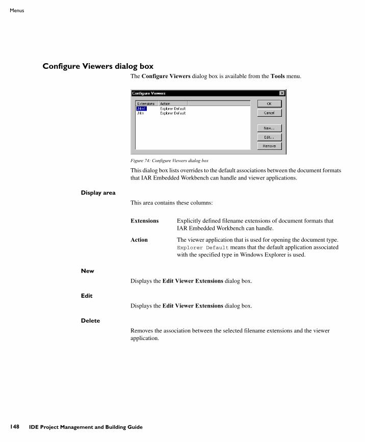
UIDEEW-1:1
148
Menus
IDE Project Management and Building Guide
Configure Viewers dialog box The Configure Viewers dialog box is available from the Tools menu.
Figure 74: Configure Viewers dialog box
This dialog box lists overrides to the default associations between the document formats that IAR Embedded Workbench can handle and viewer applications.
Display area
This area contains these columns:
New
Displays the Edit Viewer Extensions dialog box.
Edit
Displays the Edit Viewer Extensions dialog box.
Delete
Removes the association between the selected filename extensions and the viewer application.
Extensions Explicitly defined filename extensions of document formats that IAR Embedded Workbench can handle.
Action The viewer application that is used for opening the document type. Explorer Default means that the default application associated with the specified type in Windows Explorer is used.
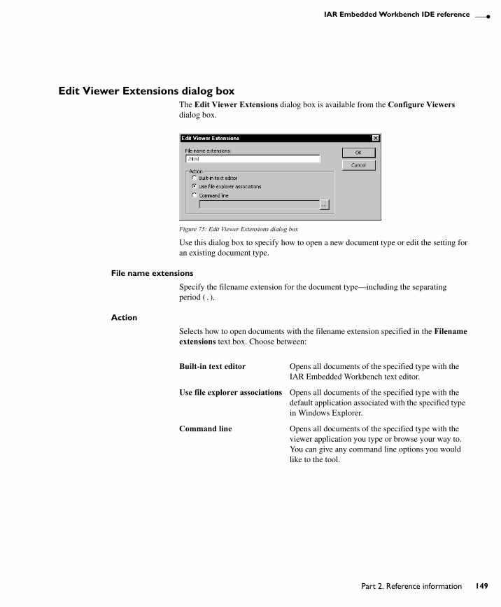
UIDEEW-1:1
Part 2. Reference information
IAR Embedded Workbench IDE reference
149
Edit Viewer Extensions dialog box The Edit Viewer Extensions dialog box is available from the Configure Viewers dialog box.
Figure 75: Edit Viewer Extensions dialog box
Use this dialog box to specify how to open a new document type or edit the setting for an existing document type.
File name extensions
Specify the filename extension for the document type—including the separating period (.).
Action
Selects how to open documents with the filename extension specified in the Filename extensions text box. Choose between:
Built-in text editor Opens all documents of the specified type with the IAR Embedded Workbench text editor.
Use file explorer associations Opens all documents of the specified type with the default application associated with the specified type in Windows Explorer.
Command line Opens all documents of the specified type with the viewer application you type or browse your way to. You can give any command line options you would like to the tool.

UIDEEW-1:1
150
Menus
IDE Project Management and Building Guide
Window menuThe Window menu provides commands for manipulating the IDE windows and changing their arrangement on the screen.
Figure 76: Window menu
The last section of the Window menu lists the currently open windows. Choose the window you want to switch to.
These commands are available:
Close Tab Closes the active tab.
Close WindowCtrl+F4
Closes the active editor window.
Split Splits an editor window horizontally or vertically into two or four panes, which means that you can see more parts of a file simultaneously.
New Vertical Editor Window Opens a new empty window next to the current editor window.
New Horizontal Editor Window
Opens a new empty window under the current editor window.
Move Tabs To Next Window Moves all tabs in the current window to the next window.
Move Tabs To Previous Window
Moves all tabs in the current window to the previous window.
Close All Tabs Except Active Closes all the tabs except the active tab.
Close All Editor Tabs Closes all tabs currently available in editor windows.

UIDEEW-1:1
Part 2. Reference information
IAR Embedded Workbench IDE reference
151
Help menuThe Help menu provides help about IAR Embedded Workbench and displays the version numbers of the user interface and of the IDE.
You can also access the Information Center from the Help menu. The Information Center is an integrated navigation system that gives easy access to the information resources you need to get started and during your project development: tutorials, example projects, user guides, support information, and release notes. It also provides shortcuts to useful sections on the IAR Systems web site.

UIDEEW-1:1
152
Menus
IDE Project Management and Building Guide

UIDEEW-1:1
Glossary
153
GlossaryThis is a general glossary for terms relevant to embedded systems programming. Some of the terms do not apply to the IAR Embedded Workbench® version that you are using.
A Absolute locationA specific memory address for an object specified in the source code, as opposed to the object being assigned a location by the linker.
Absolute segmentsSegments that have fixed locations in memory before linking.
Address expressionAn expression which has an address as its value.
ApplicationThe program developed by the user of the IAR Systems toolkit and which will be run as an embedded application on a target processor.
ArThe GNU binary utility for creating, modifying, and extracting from archives, that is, libraries. See also Iarchive.
ArchitectureA term used by computer designers to designate the structure of complex information-processing systems. It includes the kinds of instructions and data used, the memory organization and addressing, and the methods by which the system is implemented. The two main architecture types used in processor design are Harvard architecture and von Neumann architecture.
ArchiveSee Library.
Assembler directivesThe set of commands that control how the assembler operates.
Assembler languageA machine-specific set of mnemonics used to specify operations to the target processor and input or output registers or data areas. Assembler language might sometimes be preferred over C/C++ to save memory or to enhance the execution speed of the application.
Assembler optionsParameters you can specify to change the default behavior of the assembler.
AttributesSee Section attributes (ILINK).
Auto variablesThe term refers to the fact that each time the function in which the variable is declared is called, a new instance of the variable is created automatically. This can be compared with the behavior of local variables in systems using static overlay, where a local variable only exists in one instance, even if the function is called recursively. Also called local variables. Compare Register variables.
BBacktraceInformation for keeping call frame information up to date so that the IAR C-SPY® Debugger can return from a function correctly. See also Call frame information.
BankSee Memory bank.
Bank switchingSwitching between different sets of memory banks. This software technique increases a computer's usable memory by allowing different pieces of memory to occupy the same address space.
Banked codeCode that is distributed over several banks of memory. Each function must reside in only one bank.

UIDEEW-1:1
154 IDE Project Management and Building Guide
Banked dataData that is distributed over several banks of memory. Each data object must fit inside one memory bank.
Banked memoryHas multiple storage locations for the same address. See also Memory bank.
Bank-switching routinesCode that selects a memory bank.
Batch filesA text file containing operating system commands which are executed by the command line interpreter. In Unix, this is called a “shell script” because it is the Unix shell which includes the command line interpreter. Batch files can be used as a simple way to combine existing commands into new commands.
BitfieldA group of bits considered as a unit.
Block, in linker configuration file (ILINK)A continuous piece of code or data. It is either built up of blocks, overlays, and sections or it is empty. A block has a name, and the start and end address of the block can be referred to from the application. It can have attributes such as a maximum size, a specific size, or a minimum alignment. The contents can have a specific order or not.
Breakpoint1. Code breakpoint. A point in a program that, when reached, triggers some special behavior useful to the process of debugging. Generally, breakpoints are used for stopping program execution or dumping the values of some or all of the program variables. Breakpoints can be part of the program itself, or they can be set by the programmer as part of an interactive session with a debugging tool for scrutinizing the program's execution.
2. Data breakpoint. A point in memory that, when accessed, triggers some special behavior useful to the process of debugging. Generally, data breakpoints are used to stop program execution when an address location is accessed either by a read operation or a write operation.
3. Immediate breakpoint. A point in memory that, when accessed, trigger some special behavior useful in the process of debugging. Immediate breakpoints are generally used for halting the program execution in the middle of a memory access instruction (before or after the actual memory access depending on the access type) while performing some user-specified action. The execution is then resumed. This feature is only available in the simulator version of C-SPY.
CCall frame informationInformation that allows the IAR C-SPY® Debugger to show, without any runtime penalty, the complete stack of function calls—call stack—wherever the program counter is, provided that the code comes from compiled C functions. See also Backtrace.
Calling conventionA calling convention describes the way one function in a program calls another function. This includes how register parameters are handled, how the return value is returned, and which registers that will be preserved by the called function. The compiler handles this automatically for all C and C++ functions. All code written in assembler language must conform to the rules in the calling convention to be callable from C or C++, or to be able to call C and C++ functions. The C calling convention and the C++ calling conventions are not necessarily the same.
CheapAs in cheap memory access. A cheap memory access either requires few cycles to perform, or few bytes of code to implement. A cheap memory access is said to have a low cost. See Memory access cost.
ChecksumA computed value which depends on the ROM content of the whole or parts of the application, and which is stored along with the application to detect corruption of the data. The checksum is produced by the linker to be verified with the application. Several algorithms are supported. Compare CRC (cyclic redundancy checking).

UIDEEW-1:1
Glossary
155
Code bankingSee Banked code.
Code modelThe code model controls how code is generated for an application. Typically, the code model controls behavior such as how functions are called and in which code segment/section functions will be located. All object files of an application must be compiled using the same code model.
Code pointersA code pointer is a function pointer. As many microcontrollers allow several different methods of calling a function, compilers for embedded systems usually provide the users with the ability to use all these methods.
Do not confuse code pointers with data pointers.
Code segments/sectionsRead-only segments/sections that contain code. See also Segment (XLINK) and Section (ILINK).
Compilation unitSee Translation unit.
Compiler function directives (XLINK)The compiler function directives are generated by the compiler to pass information about functions and function calls to the IAR XLINK Linker. To view these directives, you must create an assembler list file. These directives are primarily intended for compilers that support static overlay, a feature which is useful in smaller microcontrollers.
Compiler optionsParameters you can specify to change the default behavior of the compiler.
CostSee Memory access cost.
CRC (cyclic redundancy checking)A number derived from, and stored with, a block of data to detect corruption. A CRC is based on polynomials and is a more advanced way of detecting errors than a simple arithmetic checksum. Compare Checksum.
C-SPY optionsParameters you can specify to change the default behavior of the IAR C-SPY Debugger.
CstartupCode that sets up the system before the application starts executing.
C-style preprocessorA preprocessor is either a stand-alone application or an integrated part of a compiler, that performs preprocessing of the input stream before the actual compilation occurs. A C-style preprocessor follows the rules set up in Standard C and implements commands like #define, #if, and #include, which are used to handle textual macro substitution, conditional compilation, and inclusion of other files.
DData bankingSee Banked data.
Data modelThe data model specifies the default memory type. This means that the data model typically controls one or more of the following: The method used and the code generated to access static and global variables, dynamically allocated data, and the runtime stack. It also controls the default pointer type and in which data segments/sections static and global variables will be located. A project can only use one data model at a time, and the same model must be used by all user modules and all library modules in the project.
Data pointersMany microcontrollers have different addressing modes to access different memory types or address spaces. Compilers for embedded systems usually have a set of different data pointer types so they can access the available memory efficiently.
Data representationHow different data types are laid out in memory and what value ranges they represent.

UIDEEW-1:1
156 IDE Project Management and Building Guide
DeclarationA specification to the compiler that an object, a variable or function, exists. The object itself must be defined in exactly one translation unit (source file). An object must either be declared or defined before it is used. Normally an object that is used in many files is defined in one source file. A declaration is normally placed in a header file that is included by the files that use the object.
For example:
/* Variable "a" exists somewhere. Function "b" takes two int parameters and returns an int. */
extern int a; int b(int, int);
DefinitionThe variable or function itself. Only one definition can exist for each variable or function in an application. See also Tentative definition.
For example:
int a;int b(int x, int y){ return x + y;}
Demangling (ILINK)To restore a mangled name to the more common C/C++ name. See also Mangling (ILINK).
Device description fileA file used by C-SPY that contains various device-specific information such as I/O registers (SFR) definitions, interrupt vectors, and control register definitions.
Device driverSoftware that provides a high-level programming interface to a particular peripheral device.
Digital signal processor (DSP)A device that is similar to a microprocessor, except that the internal CPU is optimized for use in applications involving discrete-time signal processing. In addition to standard microprocessor instructions, digital signal processors usually support a set of complex instructions to perform common signal-processing computations quickly.
Disassembly windowA C-SPY window that shows the memory contents disassembled as machine instructions, interspersed with the corresponding C source code (if available).
DWARFAn industry-standard debugging format which supports source level debugging. This is the format used by the IAR ILINK Linker for representing debug information in an object.
Dynamic initializationVariables in a program written in C are initialized during the initial phase of execution, before the main function is called. These variables are always initialized with a static value, which is determined either at compile time or at link time. This is called static initialization. In C++, variables might require initialization to be performed by executing code, for example, running the constructor of global objects, or performing dynamic memory allocation.
Dynamic memory allocationThere are two main strategies for storing variables: statically at link time, or dynamically at runtime. Dynamic memory allocation is often performed from the heap and it is the size of the heap that determines how much memory that can be used for dynamic objects and variables. The advantage of dynamic memory allocation is that several variables or objects that are not active at the same time can be stored in the same memory, thus reducing the memory requirements of an application. See also Heap memory.
Dynamic objectAn object that is allocated, created, destroyed, and released at runtime. Dynamic objects are almost always stored in memory that is dynamically allocated. Compare Static object.

UIDEEW-1:1
Glossary
157
EEEPROMElectrically Erasable, Programmable Read-Only Memory. A type of ROM that can be erased electronically, and then be re-programmed.
ELFExecutable and Linking Format, an industry-standard object file format. This is the format used by the IAR ILINK Linker. The debug information is formatted using DWARF.
Embedded C++A subset of the C++ programming language, which is intended for embedded systems programming. The fact that performance and portability are particularly important in embedded systems development was considered when defining the language.
Embedded systemA combination of hardware and software, designed for a specific purpose. Embedded systems are often part of a larger system or product.
EmulatorAn emulator is a hardware device that performs emulation of one or more derivatives of a processor family. An emulator can often be used instead of the actual microcontroller and connects directly to the printed circuit board—where the microcontroller would have been connected—via a connecting device. An emulator always behaves exactly as the processor it emulates, and is used when debugging requires all systems actuators, or when debugging device drivers.
Enea OSE Load module formatA specific ELF format that is loadable by the OSE operating system. See also ELF.
EnumerationA type which includes in its definition an exhaustive list of possible values for variables of that type. Common examples include Boolean, which takes values from the list [true, false], and day-of-week which takes values [Sunday, Monday, Tuesday, Wednesday, Thursday, Friday, Saturday]. Enumerated types are a feature of typed languages, including C and Ada.
Characters, (fixed-size) integers, and even floating-point types might be (but are not usually) considered to be (large) enumerated types.
EPROMErasable, Programmable Read-Only Memory. A type of ROM that can be erased by exposing it to ultraviolet light, and then be re-programmed.
Executable imageContains the executable image; the result of linking several relocatable object files and libraries. The file format used for an object file is UBROF for XLINK and for ILINK, ELF with embedded DWARF for debug information.
ExceptionsAn exception is an interrupt initiated by the processor hardware, or hardware that is tightly coupled with the processor, for instance, a memory management unit (MMU). The exception signals a violation of the rules of the architecture (access to protected memory), or an extreme error condition (division by zero).
Do not confuse this use of the word exception with the term exception used in the C++ language (but not in Embedded C++).
ExpensiveAs in expensive memory access. An expensive memory access either requires many cycles to perform, or many bytes of code to implement. An expensive memory access is said to have a high cost. See Memory access cost.

UIDEEW-1:1
158 IDE Project Management and Building Guide
Extended keywordsNon-standard keywords in C and C++. These usually control the definition and declaration of objects (that is, data and functions). See also Keywords.
FFillingHow to fill up bytes—with a specific fill pattern—that exists between the segments/sections in an executable image. These bytes exist because of the alignment demands on the segments/sections.
Format specifiersUsed to specify the format of strings sent by library functions such as printf. In the following example, the function call contains one format string with one format specifier, %c, that prints the value of a as a single ASCII character:
printf("a = %c", a);
GGeneral optionsParameters you can specify to change the default behavior of all tools that are included in the IDE.
Generic pointersPointers that have the ability to point to all different memory types in, for example, a microcontroller based on the Harvard architecture.
HHarvard architectureA microcontroller based on the Harvard architecture has separate data and instruction buses. This allows execution to occur in parallel. As an instruction is being fetched, the current instruction is executing on the data bus. Once the current
instruction is complete, the next instruction is ready to go. This theoretically allows for much faster execution than a von Neumann architecture, but adds some silicon complexity. Compare von Neumann architecture.
Heap memoryThe heap is a pool of memory in a system that is reserved for dynamic memory allocation. An application can request parts of the heap for its own use; once memory is allocated from the heap it remains valid until it is explicitly released back to the heap by the application. This type of memory is useful when the number of objects is not known until the application executes. Note that this type of memory is risky to use in systems with a limited amount of memory or systems that are expected to run for a very long time.
Heap sizeTotal size of memory that can be dynamically allocated.
HostThe computer that communicates with the target processor. The term is used to distinguish the computer on which the debugger is running from the microcontroller the embedded application you develop runs on.
IIarchiveThe IAR Systems utility for creating archives, that is, libraries. Iarchive is delivered with IAR Embedded Workbench.
IDE (integrated development environment)A programming environment with all necessary tools integrated into one single application.
IelfdumpcpunameThe IAR Systems utility for creating a text representation of the contents of ELF relocatable or executable image.
IelftoolThe IAR Systems utility for performing various transformations on an ELF executable image, such as fill, checksum, and format conversion.

UIDEEW-1:1
Glossary
159
ILINKThe IAR ILINK Linker which produces absolute output in the ELF/DWARF format.
ILINK configurationThe definition of available physical memories and the placement of sections—pieces of code and data—into those memories. ILINK requires a configuration to build an executable image.
ImageSee Executable image.
Include fileA text file which is included into a source file. This is often done by the preprocessor.
Initialization setup in linker configuration file (ILINK)Defines how to initialize RAM sections with their initializers. Normally, only non-constant non-noinit variables are initialized but, for example, pieces of code can be initialized as well.
Initialized segments/sectionsRead-write segments/sections that should be initialized with specific values at startup. See also Segment (XLINK) and Section (ILINK).
Inline assemblerAssembler language code that is inserted directly between C statements.
InliningAn optimization that replaces function calls with the body of the called function. This optimization increases the execution speed and can even reduce the size of the generated code.
Instruction mnemonicsA word or acronym used in assembler language to represent a machine instruction. Different processors have different instruction sets and therefore use a different set of mnemonics to represent them, such as, ADD, BR (branch), BLT (branch if less than), MOVE, LDR (load register).
Interrupt vectorA small piece of code that will be executed, or a pointer that points to code that will be executed when an interrupt occurs.
Interrupt vector tableA table containing interrupt vectors, indexed by interrupt type. This table contains the processor's mapping between interrupts and interrupt service routines and must be initialized by the programmer.
InterruptsIn embedded systems, the use of interrupts is a method of detecting external events immediately, for example a timer overflow or the pressing of a button.
Interrupts are asynchronous events that suspend normal processing and temporarily divert the flow of control through an “interrupt handler” routine. Interrupts can be caused by both hardware (I/O, timer, machine check) and software (supervisor, system call or trap instruction). Compare Trap.
IntrinsicAn adjective describing native compiler objects, properties, events, and methods.
Intrinsic functions1. Function calls that are directly expanded into specific sequences of machine code. 2. Functions called by the compiler for internal purposes (that is, floating-point arithmetic etc.).
IobjmanipThe IAR Systems utility for performing low-level manipulation of ELF object files.
KKey bindingsKey shortcuts for menu commands used in the IDE.

UIDEEW-1:1
160 IDE Project Management and Building Guide
KeywordsA fixed set of symbols built into the syntax of a programming language. All keywords used in a language are reserved—they cannot be used as identifiers (in other words, user-defined objects such as variables or procedures). See also Extended keywords.
LL-valueA value that can be found on the left side of an assignment and thus be changed. This includes plain variables and de-referenced pointers. Expressions like (x + 10) cannot be assigned a new value and are therefore not L-values.
Language extensionsTarget-specific extensions to the C language.
LibrarySee Runtime library.
Library configuration fileA file that contains a configuration of the runtime library. The file contains information about what functionality is part of the runtime environment. The file is used for tailoring a build of a runtime library. See also Runtime library.
Linker configuration file (XLINK)A file used by the IAR XLINK Linker. It contains command line options which specify the locations where the memory segments can be placed, thereby assuring that your application fits on the target chip.
Because many of the chip-specific details are specified in the linker configuration file and not in the source code, the linker configuration file also helps to make the code portable.
In particular, the linker specifies the placement of segments, the stack size, and the heap size.
Linker configuration file (ILINK)A file that contains a configuration used by the IAR ILINK Linker when building an executable image. See also ILINK configuration.
Local variableSee Auto variables.
Location counterSee Program location counter (PLC).
Logical addressSee Virtual address (logical address).
MMAC (Multiply and accumulate)A special instruction, or on-chip device, that performs a multiplication together with an addition. This is very useful when performing signal processing where many filters and transforms have the form:
The accumulator of the MAC usually has a higher precision (more bits) than normal registers. See also Digital signal processor (DSP).
Macro1. Assembler macros are user-defined sets of assembler lines that can be expanded later in the source file by referring to the given macro name. Parameters will be substituted if referred to.
2. C macro. A text substitution mechanism used during preprocessing of source files. Macros are defined using the #define preprocessing directive. The replacement text of each macro is then substituted for any occurrences of the macro name in the rest of the translation unit.
3. C-SPY macros are programs that you can write to enhance the functionality of C-SPY. A typical application of C-SPY macros is to associate them with breakpoints; when such a breakpoint is hit, the macro is run and can for example be used to simulate peripheral devices, to evaluate complex conditions, or to output a trace.
yj ci xi j+⋅i 0=
N
∑=

UIDEEW-1:1
Glossary
161
The C-SPY macro language is like a simple dialect of C, but is less strict with types.
MailboxA mailbox in an RTOS is a point of communication between two or more tasks. One task can send messages to another task by placing the message in the mailbox of the other task. Mailboxes are also known as message queues or message ports.
Mangling (ILINK)Mangling is a technique used for mapping a complex C/C++ name into a simple name. Both mangled and unmangled names can be produced for C/C++ symbols in ILINK messages.
Memory, in linker configuration file (ILINK)A physical memory. The number of units it contains and how many bits a unit consists of, are defined in the linker configuration file. The memory is always addressable from 0x0 to size -1.
Memory access costThe cost of a memory access can be in clock cycles, or in the number of bytes of code needed to perform the access. A memory which requires large instructions or many instructions is said to have a higher access cost than a memory which can be accessed with few, or small instructions.
Memory areaA region of the memory.
Memory bankThe smallest unit of continuous memory in banked memory. One memory bank at a time is visible in a microcontroller’s physical address space.
Memory mapA map of the different memory areas available to the microcontroller.
Memory modelSpecifies the memory hierarchy and how much memory the system can handle. Your application must use only one memory model at a time, and the same model must be used by all user modules and all library modules.
MicrocontrollerA microprocessor on a single integrated circuit intended to operate as an embedded system. In addition to a CPU, a microcontroller typically includes small amounts of RAM, PROM, timers, and I/O ports.
MicroprocessorA CPU contained on one (or a few) integrated circuits. A single-chip microprocessor can include other components such as memory, memory management, caches, floating-point unit, I/O ports and timers. Such devices are also known as microcontrollers.
ModuleAn object. An object file contains a module and library contains one or more objects. The basic unit of linking. A module contains definitions for symbols (exports) and references to external symbols (imports). When you compile C/C++, each translation unit produces one module.
Multi-file compilationA technique which means that the compiler compiles several source files as one compilation unit, which enables for interprocedural optimizations such as inlining, cross call, and cross jump on multiple source files in a compilation unit.
NNested interruptsA system where an interrupt can be interrupted by another interrupt is said to have nested interrupts.
Non-banked memoryHas a single storage location for each memory address in a microcontroller’s physical address space.

UIDEEW-1:1
162 IDE Project Management and Building Guide
Non-initialized memoryMemory that can contain any value at reset, or in the case of a soft reset, can remember the value it had before the reset.
No-init segments/sectionsRead-write segments/sections that should not be initialized at startup. See also Segment (XLINK) and Section (ILINK).
Non-volatile storageMemory devices such as battery-backed RAM, ROM, magnetic tape and magnetic disks that can retain data when electric power is shut off. Compare Volatile storage.
NOPNo operation. This is an instruction that does not do anything, but is used to create a delay. In pipelined architectures, the NOP instruction can be used for synchronizing the pipeline. See also Pipeline.
OObjcopyA GNU binary utility for converting an absolute object file in ELF format into an absolute object file, for example the format Motorola-std or Intel-std. See also Ielftool.
ObjectAn object file or a library member.
Object file, absoluteSee Executable image.
Object file, relocatableThe result of compiling or assembling a source file. The file format used for an object file is UBROF for XLINK and for ILINK, ELF with embedded DWARF for debug information.
OperatorA symbol used as a function, with infix syntax if it has two arguments (+, for example) or prefix syntax if it has only one (for instance, bitwise negation, ~). Many languages use operators for built-in functions such as arithmetic and logic.
Operator precedenceEach operator has a precedence number assigned to it that determines the order in which the operator and its operands are evaluated. The highest precedence operators are evaluated first. Use parentheses to group operators and operands to control the order in which the expressions are evaluated.
OptionsA set of commands that control the behavior of a tool, for example the compiler or linker. The options can be specified on the command line or via the IDE.
Output imageThe resulting application after linking. This term is equivalent to executable image, which is the term used in the IAR Systems user documentation.
Overlay, in linker configuration file (ILINK)Like a block, but it contains several overlaid entities, each built up of blocks, overlays, and sections. The size of an overlay is determined by its largest constituent.
PParameter passingSee Calling convention.
Peripheral unitA hardware component other than the processor, for example memory or an I/O device.
PipelineA structure that consists of a sequence of stages through which a computation flows. New operations can be initiated at the start of the pipeline even though other operations are already in progress through the pipeline.
Placement, in linker configuration file (ILINK)How to place blocks, overlays, and sections into a region. It determines how pieces of code and data are actually placed in the available physical memory.

UIDEEW-1:1
Glossary
163
PointerAn object that contains an address to another object of a specified type.
#pragmaDuring compilation of a C/C++ program, the #pragma preprocessing directive causes the compiler to behave in an implementation-defined manner. This can include, for example, producing output on the console, changing the declaration of a subsequent object, changing the optimization level, or enabling/disabling language extensions.
Pre-emptive multitaskingAn RTOS task is allowed to run until a higher priority process is activated. The higher priority task might become active as the result of an interrupt. The term preemptive indicates that although a task is allotted to run a given length of time (a timeslice), it might lose the processor at any time. Each time an interrupt occurs, the task scheduler looks for the highest priority task that is active and switches to that task. If the located task is different from the task that was executing before the interrupt, the previous task is suspended at the point of interruption.
Compare Round Robin.
Preprocessing directivesA set of directives that are executed before the parsing of the actual code is started.
PreprocessorSee C-style preprocessor.
Processor variantThe different chip setups that the compiler supports.
Program counter (PC)A special processor register that is used to address instructions. Compare Program location counter (PLC).
Program location counter (PLC)Used in the IAR Assembler to denote the code address of the current instruction. The PLC is represented by a special symbol (typically $) that can be used in arithmetic expressions. Also called simply location counter (LC).
ProjectThe user application development project.
Project optionsGeneral options that apply to an entire project, for example the target processor that the application will run on.
PROMProgrammable Read-Only Memory. A type of ROM that can be programmed only once.
QQualifiersSee Type qualifiers.
RRange, in linker configuration fileA range of consecutive addresses in a memory. A region is built up of ranges.
Read-only segments/sectionsSegments/sections that contain code or constants. See also Segment (XLINK) and Section (ILINK).
Real-time operating system (RTOS)An operating system which guarantees the latency between an interrupt being triggered and the interrupt handler starting, and how tasks are scheduled. An RTOS is typically much smaller than a normal desktop operating system. Compare Real-time system.
Real-time systemA computer system whose processes are time-sensitive. Compare Real-time operating system (RTOS).
Region, in linker configuration fileA set of non-overlapping ranges. The ranges can lie in one or more memories. For ILINK, blocks, overlays, and sections are placed into regions in the linker configuration file. For XLINK, the segments are placed in regions.

UIDEEW-1:1
164 IDE Project Management and Building Guide
Region expression, in linker configuration file (ILINK)A region built up from region literals, regions, and the common set operations possible in the linker configuration file.
Region literal, in linker configuration file (ILINK)A literal that defines a set of one or more non-overlapping ranges in a memory.
RegisterA small on-chip memory unit, usually just one or a few bytes in size, which is particularly efficient to access and therefore often reserved as a temporary storage area during program execution.
Register constantA register constant is a value that is loaded into a dedicated processor register when the system is initialized. The compiler can then generate code that assumes that the constants are present in the dedicated registers.
Register lockingRegister locking means that the compiler can be instructed that some processor registers shall not be used during normal code generation. This is useful in many situations. For example, some parts of a system might be written in assembler language to gain speed. These parts might be given dedicated processor registers. Or the register might be used by an operating system, or by other third-party software.
Register variablesTypically, register variables are local variables that are placed in registers instead of on the (stack) frame of the function. Register variables are much more efficient than other variables because they do not require memory accesses, so the compiler can use shorter/faster instructions when working with them. See also Auto variables.
RelayA synonym to veneer, see Veneer.
Relocatable segments/sectionsSegments/sections that have no fixed location in memory before linking.
ResetA reset is a restart from the initial state of a system. A reset can originate from hardware (hard reset), or from software (soft reset). A hard reset can usually not be distinguished from the power-on condition, which a soft reset can be.
ROM-monitorA piece of embedded software designed specifically for use as a debugging tool. It resides in the ROM of the evaluation board chip and communicates with a debugger via a serial port or network connection. The ROM-monitor provides a set of primitive commands to view and modify memory locations and registers, create and remove breakpoints, and execute your application. The debugger combines these primitives to fulfill higher-level requests like program download and single-step.
Round RobinTask scheduling in an operating system, where all tasks have the same priority level and are executed in turn, one after the other. Compare Pre-emptive multitasking.
RTOSSee Real-time operating system (RTOS).
Runtime libraryA collection of relocatable object files that will be included in the executable image only if referred to from an object file, in other words conditionally linked.
Runtime model attributesA mechanism that is designed to prevent modules that are not compatible to be linked into an application. A runtime attribute is a pair constituted of a named key and its corresponding value.
For XLINK, two modules can only be linked together if they have the same value for each key that they both define. ILINK uses the runtime model attributes when automatically choosing a library, to verify that the correct one is used.
R-valueA value that can be found on the right side of an assignment. This is just a plain value. See also L-value.

UIDEEW-1:1
Glossary
165
SSaturation arithmeticsMost, if not all, C and C++ implementations use mod–2N 2-complement-based arithmetics where an overflow wraps the value in the value domain, that is, (127 + 1) = -128. Saturation arithmetics, on the other hand, does not allow wrapping in the value domain, for instance, (127 + 1) = 127, if 127 is the upper limit. Saturation arithmetics is often used in signal processing, where an overflow condition would have been fatal if value wrapping had been allowed.
SchedulerThe part of an RTOS that performs task-switching. It is also responsible for selecting which task that should be allowed to run. Many scheduling algorithms exist, but most of them are either based on static scheduling (performed at compile-time), or on dynamic scheduling (where the actual choice of which task to run next is taken at runtime, depending on the state of the system at the time of the task-switch). Most real-time systems use static scheduling, because it makes it possible to prove that the system will not violate the real-time requirements.
ScopeThe section of an application where a function or a variable can be referenced by name. The scope of an item can be limited to file, function, or block.
Section (ILINK)An entity that either contains data or text. Typically, one or more variables, or functions. A section is the smallest linkable unit.
Section attributes (ILINK)Each section has a name and an attribute. The attribute defines what a section contains, that is, if the section content is read-only, read/write, code, data, etc.
Section fragment (ILINK)A part of a section, typically a variable or a function.
Section selection (ILINK)In the linker configuration file, defining a set of sections by using section selectors. A section belongs to the most restrictive section selector if it can be part of more than one selection. Three different selectors can be used individually or in conjunction to select the set of sections: section attribute (selecting by the section content), section name (selecting by the section name), and object name (selecting from a specific object).
Segment (XLINK)A chunk of data or code that should be mapped to a physical location in memory. The segment can either be placed in RAM or in ROM.
Segment map (XLINK)A set of segments and their locations. This map is part of the linker list file.
Segment part (XLINK)A part of a segment, typically a variable or a function.
SemaphoreA semaphore is a type of flag that is used for guaranteeing exclusive access to resources. The resource can be a hardware port, a configuration memory, or a set of variables. If several tasks must access the same resource, the parts of the code (the critical sections) that access the resource must be made exclusive for every task. This is done by obtaining the semaphore that protects that resource, thus blocking all other tasks from it. If another task wishes to use the resource, it also must obtain the semaphore. If the semaphore is already in use, the second task must wait until the semaphore is released. After the semaphore is released, the second task is allowed to execute and can obtain the semaphore for its own exclusive access.
Severity levelThe level of seriousness of the diagnostic response from the assembler, compiler, or debugger, when it notices that something is wrong. Typical severity levels are remarks, warnings, errors, and fatal errors. A remark just points to a possible problem, while a fatal error means that the programming tool exits without finishing.

UIDEEW-1:1
166 IDE Project Management and Building Guide
SharingA physical memory that can be addressed in several ways. For ILINK, defined in the linker configuration file. For XLINK, the command line option -U is used to define it.
Short addressingMany microcontrollers have special addressing modes for efficient access to internal RAM and memory mapped I/O. Short addressing is therefore provided as an extended feature by many compilers for embedded systems. See also Data pointers.
Side effectAn expression in C or C++ is said to have a side-effect if it changes the state of the system. Examples are assignments to a variable, or using a variable with the post-increment operator. The C and C++ standards state that a variable that is subject to a side-effect should not be used more that once in an expression. As an example, this statement violates that rule:
*d++ = *d;
SignalSignals provide event-based communication between tasks. A task can wait for one or more signals from other tasks. Once a task receives a signal it waits for, execution continues. A task in an RTOS that waits for a signal does not use any processing time, which allows other tasks to execute.
Simple formatThe Simple output format is a format that supplies the bytes of the application in a way that is easy to manipulate. If you want to modify the contents of some addresses in the application but the standard linker options are not sufficient, use the Simple output format. Generate the application in the Simple format and then write a small utility (example source code is delivered with XLINK) that modifies the output.
SimulatorA debugging tool that runs on the host and behaves as similar to the target processor as possible. A simulator is used to debug the application when the hardware is unavailable, or not needed for proper debugging. A simulator is usually not connected to any physical peripheral devices. A simulated processor is often slower, or even much slower, than the real hardware.
Single steppingExecuting one instruction or one C statement at a time in the debugger.
Skeleton codeAn incomplete code framework that allows the user to specialize the code.
Special function register (SFR)A register that is used to read and write to the hardware components of the microcontroller.
Stack framesData structures containing data objects like preserved registers, local variables, and other data objects that must be stored temporary for a particular scope (usually a function).
Earlier compilers usually had a fixed size and layout on a stack frame throughout a complete function, while modern compilers might have a very dynamic layout and size that can change anywhere and anytime in a function.
Stack segments/sectionsThe segment/section or segments/sections that reserve space for the stack(s). Most processors use the same stack for calls and parameters, but some have separate stacks.
Standard librariesThe C and C++ library functions as specified by the C and C++ standard, and support routines for the compiler, like floating-point routines.
Static objectAn object whose memory is allocated at link-time and is created during system startup (or at first use). Compare Dynamic object.

UIDEEW-1:1
Glossary
167
Static overlay (XLINK)Instead of using a dynamic allocation scheme for parameters and auto variables, the linker allocates space for parameters and auto variables at link time. This generates a worst-case scenario of stack usage, but might be preferable for small chips with expensive stack access or no stack access at all.
Statically allocated memoryThis kind of memory is allocated once and for all at link-time, and remains valid all through the execution of the application. Variables that are either global or declared static are allocated this way.
Structure valueA collecting names for structs and unions. A struct is a collection of data object placed sequentially in memory (possibly with pad bytes between them). A union is a collection of data sharing the same memory location.
Symbolic locationA location that uses a symbolic name because the exact address is unknown.
TTarget1. An architecture. 2. A piece of hardware. The particular embedded system you are developing the application for. The term is usually used to distinguish the system from the host system.
Task (thread)A task is an execution thread in a system. Systems that contain many tasks that execute in parallel are called multitasking systems. Because a processor only executes one instruction stream at the time, most systems implement some sort of task-switch mechanism (often called context switch) so that all tasks get their share of processing time. The process of determining which task that should be allowed to run next is called scheduling. Two common scheduling methods are Pre-emptive multitasking and Round Robin.
Tentative definitionA variable that can be defined in multiple files, provided that the definition is identical and that it is an absolute variable.
Terminal I/OA simulated terminal window in C-SPY.
TimerA peripheral that counts independent of the program execution.
TimesliceThe (longest) time an RTOS allows a task to run without running the task-scheduling algorithm. A task might be allowed to execute during several consecutive timeslices before being switched out. A task might also not be allowed to use its entire time slice, for example if, in a preemptive system, a higher priority task is activated by an interrupt.
Translation unitA source file together with all the header files and source files included via the preprocessor directive #include, except for the lines skipped by conditional preprocessor directives such as #if and #ifdef.
TrapA trap is an interrupt initiated by inserting a special instruction into the instruction stream. Many systems use traps to call operating system functions. Another name for trap is software interrupt.
Type qualifiersIn Standard C/C++, const or volatile. IAR Systems compilers usually add target-specific type qualifiers for memory and other type attributes.
UUBROF (Universal Binary Relocatable Object Format)File format produced by some of the IAR Systems programming tools, if your product package includes the XLINK linker.

UIDEEW-1:1
168 IDE Project Management and Building Guide
VValue expressions, in linker configuration fileA constant number that can be built up out of expressions that has a syntax similar to C expressions.
VeneerA small piece of code that is inserted as a springboard between caller and callee when:
• There is a mismatch in mode
• The call instruction does not reach its destination.
Virtual address (logical address)An address that must be translated by the compiler, linker or the runtime system into a physical memory address before it is used. The virtual address is the address seen by the application, which can be different from the address seen by other parts of the system.
Virtual spaceAn IAR Embedded Workbench Editor feature which allows you to place the insertion point outside of the area where there are actual characters.
Volatile storageData stored in a volatile storage device is not retained when the power to the device is turned off. To preserve data during a power-down cycle, you should store it in non-volatile storage. This should not be confused with the C keyword volatile. Compare Non-volatile storage.
von Neumann architectureA computer architecture where both instructions and data are transferred over a common data channel. Compare Harvard architecture.
WWatchpointsWatchpoints keep track of the values of C variables or expressions in the C-SPY Watch window as the application is being executed.
XXARAn IAR tool that creates archives (libraries) in the UBROF format. XAR is delivered with IAR Embedded Workbench.
XLIBAn IAR tool that creates archives (libraries) in the UBROF format, listing object code, converting and absolute object file into an absolute object file in another format. XLIB is delivered with IAR Embedded Workbench.
XLINKThe IAR XLINK Linker which uses the UBROF output format.
ZZero-initialized segments/sectionsSegments/sections that should be initialized to zero at startup. See also Segment (XLINK) and Section (ILINK).
Zero-overhead loopA loop in which the loop condition, including branching back to the beginning of the loop, does not take any time at all. This is usually implemented as a special hardware feature of the processor and is not available in all architectures.
ZoneDifferent processors have widely differing memory architectures. Zone is the term C-SPY uses for a named memory area. For example, on processors with separately addressable code and data memory there would be at least two zones. A processor with an intricate banked memory scheme might have several zones.

UIDEEW-1:1
Index
169
Aabsolute location, definition of . . . . . . . . . . . . . . . . . . . . . 153absolute segments, definition of . . . . . . . . . . . . . . . . . . . . 153Add Files (Workspace window context menu) . . . . . . . . . . 75Add Group (Workspace window context menu) . . . . . . . . . 75address expression, definition of . . . . . . . . . . . . . . . . . . . . 153Alias (Key bindings option) . . . . . . . . . . . . . . . . . . . . . . . 124application
definition of . . . . . . . . . . . . . . . . . . . . . . . . . . . . . . . . . 153testing . . . . . . . . . . . . . . . . . . . . . . . . . . . . . . . . . . . . . . 44
architecture, definition of . . . . . . . . . . . . . . . . . . . . . . . . . 153archive, definition of . . . . . . . . . . . . . . . . . . . . . . . . . . . . . 153argument variables . . . . . . . . . . . . . . . . . . . . . . . . . . . . . . 145
environment variables . . . . . . . . . . . . . . . . . . . . . . . . . 118summary . . . . . . . . . . . . . . . . . . . . . . . . . . . . . . . . . . . 117
Arguments (External editor option) . . . . . . . . . . . . . . . . . 129ar, definition of . . . . . . . . . . . . . . . . . . . . . . . . . . . . . . . . . 153asm (filename extension) . . . . . . . . . . . . . . . . . . . . . . . . . . 65assembler comments, text style in editor. . . . . . . . . . . . . . . 52assembler directives
definition of . . . . . . . . . . . . . . . . . . . . . . . . . . . . . . . . . 153text style in editor . . . . . . . . . . . . . . . . . . . . . . . . . . . . . 52
assembler language, definition of . . . . . . . . . . . . . . . . . . . 153assembler options, definition of . . . . . . . . . . . . . . . . . . . . 153Assembler source file (Workspace window icon) . . . . . . . . 73assembler, command line version . . . . . . . . . . . . . . . . . . . . 25assert, in built applications . . . . . . . . . . . . . . . . . . . . . . . . . 33assumptions, programming experience . . . . . . . . . . . . . . . . 17attributes on sections, definition of . . . . . . . . . . . . . . . . . . 165Auto indent (editor option) . . . . . . . . . . . . . . . . . . . . . . . . 126axx (filename extension) . . . . . . . . . . . . . . . . . . . . . . . . . . . 65
BBackground color (IDE Tools option). . . . . . . . . . . . . . . . 132backtrace information, definition of . . . . . . . . . . . . . . . . . 153bank switching, definition of. . . . . . . . . . . . . . . . . . . . . . . 153banked code, definition of. . . . . . . . . . . . . . . . . . . . . . . . . 153
banked data, definition of . . . . . . . . . . . . . . . . . . . . . . . . . 154banked memory, definition of . . . . . . . . . . . . . . . . . . . . . . 154bank-switching routines, definition of. . . . . . . . . . . . . . . . 154Base (Register filter option) . . . . . . . . . . . . . . . . . . . . . . . 141bat (filename extension) . . . . . . . . . . . . . . . . . . . . . . . . . . . 65Batch Build. . . . . . . . . . . . . . . . . . . . . . . . . . . . . . . . . . . . . 43Batch Build Configuration dialog box (Project menu) . . . 120Batch Build dialog box (Project menu). . . . . . . . . . . . . . . 119batch files
definition of . . . . . . . . . . . . . . . . . . . . . . . . . . . . . . . . . 154specifying from the Tools menu. . . . . . . . . . . . . . . . . . . 30
bin (subdirectory) . . . . . . . . . . . . . . . . . . . . . . . . . . . . . . . . 63bin, common (subdirectory) . . . . . . . . . . . . . . . . . . . . . . . . 64bitfield, definition of . . . . . . . . . . . . . . . . . . . . . . . . . . . . . 154blank (source code control icon) . . . . . . . . . . . . . . . . . . . . . 77Block, definition of . . . . . . . . . . . . . . . . . . . . . . . . . . . . . . 154Body (b) (Configure auto indent option). . . . . . . . . . . . . . 128bold style, in this guide . . . . . . . . . . . . . . . . . . . . . . . . . . . . 22bookmarks
adding . . . . . . . . . . . . . . . . . . . . . . . . . . . . . . . . . . . . . . 56showing in editor . . . . . . . . . . . . . . . . . . . . . . . . . . . . . 127
breakpointsdefinition of . . . . . . . . . . . . . . . . . . . . . . . . . . . . . . . . . 154settings. . . . . . . . . . . . . . . . . . . . . . . . . . . . . . . . . . . . . 115
-build (iarbuild command line option) . . . . . . . . . . . . . . . . 45Build Actions . . . . . . . . . . . . . . . . . . . . . . . . . . . . . . . . . . . 43build configuration
creating . . . . . . . . . . . . . . . . . . . . . . . . . . . . . . . . . . . . . 35definition of . . . . . . . . . . . . . . . . . . . . . . . . . . . . . . . . . . 33
Build window (View menu) . . . . . . . . . . . . . . . . . . . . . . . . 90building
commands for . . . . . . . . . . . . . . . . . . . . . . . . . . . . . . . . 43from the command line . . . . . . . . . . . . . . . . . . . . . . . . . 45options . . . . . . . . . . . . . . . . . . . . . . . . . . . . . . . . . . . . . 134pre- and post-actions . . . . . . . . . . . . . . . . . . . . . . . . . . . 43the process . . . . . . . . . . . . . . . . . . . . . . . . . . . . . . . . . . . 41
Index

UIDEEW-1:1
170 IDE Project Management and Building Guide
CC comments, text style in editor . . . . . . . . . . . . . . . . . . . . . 52C keywords, text style in editor. . . . . . . . . . . . . . . . . . . . . . 52C source file (Workspace window icon) . . . . . . . . . . . . . . . 73c (filename extension). . . . . . . . . . . . . . . . . . . . . . . . . . . . . 65call frame information, definition of . . . . . . . . . . . . . . . . . 154calling convention, definition of . . . . . . . . . . . . . . . . . . . . 154category, in Options dialog box. . . . . . . . . . . . . . . . . . 42, 116cfg (filename extension) . . . . . . . . . . . . . . . . . . . . . . . . . . . 65cheap memory access, definition of . . . . . . . . . . . . . . . . . 154Check In Files dialog box . . . . . . . . . . . . . . . . . . . . . . . . . . 79Check In (Source code control menu). . . . . . . . . . . . . . . . . 76Check Out Files dialog box. . . . . . . . . . . . . . . . . . . . . . . . . 80Check Out (Source code control menu) . . . . . . . . . . . . . . . 76checkmark (source code control icon). . . . . . . . . . . . . . . . . 77checksum, definition of. . . . . . . . . . . . . . . . . . . . . . . . . . . 154chm (filename extension) . . . . . . . . . . . . . . . . . . . . . . . . . . 65-clean (iarbuild command line option) . . . . . . . . . . . . . . . . 45Clean (Workspace window context menu) . . . . . . . . . . . . . 75CLIB, documentation . . . . . . . . . . . . . . . . . . . . . . . . . . . . . 20Close Workspace (File menu) . . . . . . . . . . . . . . . . . . . . . . . 96code
banked, definition of . . . . . . . . . . . . . . . . . . . . . . . . . . 153skeleton, definition of . . . . . . . . . . . . . . . . . . . . . . . . . 166testing . . . . . . . . . . . . . . . . . . . . . . . . . . . . . . . . . . . . . . 44
code integrity . . . . . . . . . . . . . . . . . . . . . . . . . . . . . . . . . . . 39code model, definition of . . . . . . . . . . . . . . . . . . . . . . . . . 155code pointers, definition of . . . . . . . . . . . . . . . . . . . . . . . . 155code sections, definition of . . . . . . . . . . . . . . . . . . . . . . . . 155code templates, using in editor . . . . . . . . . . . . . . . . . . . . . . 53command line options
specifying from the Tools menu. . . . . . . . . . . . . . . . . . . 30typographic convention . . . . . . . . . . . . . . . . . . . . . . . . . 21
command prompt icon, in this guide . . . . . . . . . . . . . . . . . . 22Command (External editor option) . . . . . . . . . . . . . . . . . . 129Common Fonts (IDE Options dialog box) . . . . . . . . . . . . 122common (directory) . . . . . . . . . . . . . . . . . . . . . . . . . . . . . . 64Compare (Source code control menu). . . . . . . . . . . . . . . . . 76
Compile (Workspace window context menu) . . . . . . . . . . . 75compiler function directives, definition of . . . . . . . . . . . . 155compiler options, definition of . . . . . . . . . . . . . . . . . . . . . 155compiler, command line version . . . . . . . . . . . . . . . . . . . . . 25computer style, typographic convention . . . . . . . . . . . . . . . 21config (subdirectory). . . . . . . . . . . . . . . . . . . . . . . . . . . . . . 63configuration file for linker, definition of . . . . . . . . . . . . . 159Configurations for project dialog box (Project menu) . . . . 113Configure Auto Indent (IDE Options dialog box) . . . . . . . 127Configure Tools (Tools menu) . . . . . . . . . . . . . . . . . . . . . 143Configure Viewers dialog box (Tools menu). . . . . . . . . . . 148$CONFIG_NAME$ (argument variable) . . . . . . . . . . . . . 117config, common (subdirectory) . . . . . . . . . . . . . . . . . . . . . . 65Connect Project to SCC Project(Source code control menu) . . . . . . . . . . . . . . . . . . . . . . . . 77Control file (Workspace window icon) . . . . . . . . . . . . . . . . 73conventions, used in this guide . . . . . . . . . . . . . . . . . . . . . . 21Copy (button) . . . . . . . . . . . . . . . . . . . . . . . . . . . . . . . . . . . 71copyright notice . . . . . . . . . . . . . . . . . . . . . . . . . . . . . . . . . . 2cost. See memory access costcpp (filename extension). . . . . . . . . . . . . . . . . . . . . . . . . . . 65CRC, definition of. . . . . . . . . . . . . . . . . . . . . . . . . . . . . . . 155Create New Project dialog box (Project menu) . . . . . . . . . 115cstartup (system startup code)
definition of . . . . . . . . . . . . . . . . . . . . . . . . . . . . . . . . . 155stack pointers not valid until reaching . . . . . . . . . . . . . 139
$CUR_DIR$ (argument variable) . . . . . . . . . . . . . . . . . . . 117$CUR_LINE$ (argument variable) . . . . . . . . . . . . . . . . . . 117custom build . . . . . . . . . . . . . . . . . . . . . . . . . . . . . . . . . . . . 45
using . . . . . . . . . . . . . . . . . . . . . . . . . . . . . . . . . . . . . . . 46custom tool configuration . . . . . . . . . . . . . . . . . . . . . . . . . . 45C-SPY options
definition of . . . . . . . . . . . . . . . . . . . . . . . . . . . . . . . . . 155in Options dialog box. . . . . . . . . . . . . . . . . . . . . . . . . . 117
C-style preprocessor, definition of . . . . . . . . . . . . . . . . . . 155C/C++ syntax styles, options . . . . . . . . . . . . . . . . . . . . . . 131C++ comments, text style in editor . . . . . . . . . . . . . . . . . . . 52C++ keywords, text style in editor . . . . . . . . . . . . . . . . . . . 52C++ source file (Workspace window icon) . . . . . . . . . . . . . 73C++ terminology. . . . . . . . . . . . . . . . . . . . . . . . . . . . . . . . . 21

UIDEEW-1:1
Index
171
Ddat (filename extension) . . . . . . . . . . . . . . . . . . . . . . . . . . . 65data model, definition of . . . . . . . . . . . . . . . . . . . . . . . . . . 155data pointers, definition of . . . . . . . . . . . . . . . . . . . . . . . . 155data representation, definition of. . . . . . . . . . . . . . . . . . . . 155$DATE$ (argument variable) . . . . . . . . . . . . . . . . . . . . . . 117dbg (filename extension). . . . . . . . . . . . . . . . . . . . . . . . . . . 65dbgt (filename extension) . . . . . . . . . . . . . . . . . . . . . . . . . . 65ddf (filename extension) . . . . . . . . . . . . . . . . . . . . . . . . . . . 65Debug Log window (View menu) . . . . . . . . . . . . . . . . . . . . 93Debug without downloading text box . . . . . . . . . . . . . . . . . 71Debug (Configuration factory setting) . . . . . . . . . . . . . . . 115Debugger (IDE Options dialog box) . . . . . . . . . . . . . . . . . 137declaration, definition of . . . . . . . . . . . . . . . . . . . . . . . . . . 156default installation path. . . . . . . . . . . . . . . . . . . . . . . . . . . . 63Default integer format (IDE option) . . . . . . . . . . . . . . . . . 138definition, definition of . . . . . . . . . . . . . . . . . . . . . . . . . . . 156demangling, definition of . . . . . . . . . . . . . . . . . . . . . . . . . 156dep (filename extension) . . . . . . . . . . . . . . . . . . . . . . . . . . . 66development environment, introduction . . . . . . . . . . . . . . . 25device description files . . . . . . . . . . . . . . . . . . . . . . . . . . . . 63
definition of . . . . . . . . . . . . . . . . . . . . . . . . . . . . . . . . . 156device driver, definition of . . . . . . . . . . . . . . . . . . . . . . . . 156device selection files . . . . . . . . . . . . . . . . . . . . . . . . . . . . . . 63digital signal processor, definition of . . . . . . . . . . . . . . . . 156directories
common . . . . . . . . . . . . . . . . . . . . . . . . . . . . . . . . . . . . . 64root . . . . . . . . . . . . . . . . . . . . . . . . . . . . . . . . . . . . . . . . 63
directory structure. . . . . . . . . . . . . . . . . . . . . . . . . . . . . . . . 63Disassembly window, definition of . . . . . . . . . . . . . . . . . . 156disclaimer . . . . . . . . . . . . . . . . . . . . . . . . . . . . . . . . . . . . . . . 2Disconnect Project from SCC Project (Source code control menu) . . . . . . . . . . . . . . . . . . . . . . . . . . . . . . . . . . . . . . . . . 77DLIB library functions, reference information . . . . . . . . . . 51DLIB, documentation . . . . . . . . . . . . . . . . . . . . . . . . . . . . . 20dni (filename extension) . . . . . . . . . . . . . . . . . . . . . . . . . . . 66dockable windows. . . . . . . . . . . . . . . . . . . . . . . . . . . . . . . . 27document conventions. . . . . . . . . . . . . . . . . . . . . . . . . . . . . 21
documentation . . . . . . . . . . . . . . . . . . . . . . . . . . . . . . . . . . 63online . . . . . . . . . . . . . . . . . . . . . . . . . . . . . . . . . . . . . . . 64overview of guides . . . . . . . . . . . . . . . . . . . . . . . . . . . . . 19overview of this guide . . . . . . . . . . . . . . . . . . . . . . . . . . 19this guide . . . . . . . . . . . . . . . . . . . . . . . . . . . . . . . . . . . . 17
doc, common (subdirectory) . . . . . . . . . . . . . . . . . . . . . . . . 65drag-and-drop
of files in Workspace window . . . . . . . . . . . . . . . . . . . . 35text in editor window . . . . . . . . . . . . . . . . . . . . . . . . . . . 51
drivers (subdirectory) . . . . . . . . . . . . . . . . . . . . . . . . . . . . . 64DSP. See digital signal processorDWARF, definition of . . . . . . . . . . . . . . . . . . . . . . . . . . . . 156dxx (filename extension). . . . . . . . . . . . . . . . . . . . . . . . . . . 65Dynamic Data Exchange (DDE). . . . . . . . . . . . . . . . . . . . . 57
calling external editor . . . . . . . . . . . . . . . . . . . . . . . . . 129dynamic initialization, definition of . . . . . . . . . . . . . . . . . 156dynamic memory allocation, definition of . . . . . . . . . . . . 156dynamic object, definition of . . . . . . . . . . . . . . . . . . . . . . 156
EEdit Filename Extensions dialog box (Tools menu) . . . . . 147Edit menu . . . . . . . . . . . . . . . . . . . . . . . . . . . . . . . . . . . . . . 97Edit Viewer Extensions (Tools menu) . . . . . . . . . . . . . . . . 149editing source files . . . . . . . . . . . . . . . . . . . . . . . . . . . . . . . 49edition, of this guide . . . . . . . . . . . . . . . . . . . . . . . . . . . . . . . 2editor
code templates . . . . . . . . . . . . . . . . . . . . . . . . . . . . . . . . 53commands . . . . . . . . . . . . . . . . . . . . . . . . . . . . . . . . . . . 51customizing the environment . . . . . . . . . . . . . . . . . . . . . 57external . . . . . . . . . . . . . . . . . . . . . . . . . . . . . . . . . . . . . 57indentation . . . . . . . . . . . . . . . . . . . . . . . . . . . . . . . . . . . 52keyboard commands . . . . . . . . . . . . . . . . . . . . . . . . . . . 86matching parentheses and brackets . . . . . . . . . . . . . . . . 53options . . . . . . . . . . . . . . . . . . . . . . . . . . . . . . . . . . . . . 125shortcut to functions. . . . . . . . . . . . . . . . . . . . . . . . . 56, 83splitter controls . . . . . . . . . . . . . . . . . . . . . . . . . . . . . . . 82status bar, using in . . . . . . . . . . . . . . . . . . . . . . . . . . . . . 53using . . . . . . . . . . . . . . . . . . . . . . . . . . . . . . . . . . . . . . . 49

UIDEEW-1:1
172 IDE Project Management and Building Guide
Editor Colors and Fonts (IDE Options dialog box) . . . . . . 131Editor Font (Editor colors and fonts option) . . . . . . . . . . . 131Editor Setup Files (IDE Options dialog box) . . . . . . . . . . 130editor setup files, options . . . . . . . . . . . . . . . . . . . . . . . . . 130Editor window . . . . . . . . . . . . . . . . . . . . . . . . . . . . . . . . . . 81Editor (External editor option) . . . . . . . . . . . . . . . . . . . . . 129Editor (IDE Options dialog box). . . . . . . . . . . . . . . . . . . . 125EEPROM, definition of. . . . . . . . . . . . . . . . . . . . . . . . . . . 157ELF, definition of . . . . . . . . . . . . . . . . . . . . . . . . . . . . . . . 157Embedded C++ Technical Committee . . . . . . . . . . . . . . . . 21Embedded C++, definition of . . . . . . . . . . . . . . . . . . . . . . 157embedded system, definition of . . . . . . . . . . . . . . . . . . . . 157Embedded Workbench
editor . . . . . . . . . . . . . . . . . . . . . . . . . . . . . . . . . . . . . . . 49exiting from . . . . . . . . . . . . . . . . . . . . . . . . . . . . . . . . . . 27layout . . . . . . . . . . . . . . . . . . . . . . . . . . . . . . . . . . . . . . . 27main window . . . . . . . . . . . . . . . . . . . . . . . . . . . . . . 26, 70reference information. . . . . . . . . . . . . . . . . . . . . . . . . . . 69running. . . . . . . . . . . . . . . . . . . . . . . . . . . . . . . . . . . . . . 26version number, displaying . . . . . . . . . . . . . . . . . . . . . 151
emulator (C-SPY driver), definition of . . . . . . . . . . . . . . . 157Enable graphical stack display and stack usagetracking (Stack option) . . . . . . . . . . . . . . . . . . . . . . . . . . . 139Enable virtual space (editor option) . . . . . . . . . . . . . . . . . 127Enea OSE load module format, definition of . . . . . . . . . . 157enumeration, definition of. . . . . . . . . . . . . . . . . . . . . . . . . 157environment variables, as argument variables . . . . . . . . . . 118EOL character (editor option) . . . . . . . . . . . . . . . . . . . . . . 126EPROM, definition of . . . . . . . . . . . . . . . . . . . . . . . . . . . . 157Erase Memory dialog box. . . . . . . . . . . . . . . . . . . . . . . . . 112ewd (filename extension) . . . . . . . . . . . . . . . . . . . . . . . . . . 66ewp (filename extension) . . . . . . . . . . . . . . . . . . . . . . . . . . 66ewplugin (filename extension) . . . . . . . . . . . . . . . . . . . . . . 66eww (filename extension) . . . . . . . . . . . . . . . . . . . . . . . . . . 66
the workspace file . . . . . . . . . . . . . . . . . . . . . . . . . . . . . 27$EW_DIR$ (argument variable) . . . . . . . . . . . . . . . . . . . . 117examples (subdirectory) . . . . . . . . . . . . . . . . . . . . . . . . . . . 64exceptions, definition of . . . . . . . . . . . . . . . . . . . . . . . . . . 157executable image, definition of . . . . . . . . . . . . . . . . . . . . . 157$EXE_DIR$ (argument variable) . . . . . . . . . . . . . . . . . . . 117
Exit (File menu) . . . . . . . . . . . . . . . . . . . . . . . . . . . . . . . . . 27expensive memory access, definition of . . . . . . . . . . . . . . 157extended command line file . . . . . . . . . . . . . . . . . . . . . . . . 67extended keywords, definition of . . . . . . . . . . . . . . . . . . . 158extensions. See filename extensions or language extensionsExternal Editor (IDE Options dialog box). . . . . . . . . . . . . 128external editor, using. . . . . . . . . . . . . . . . . . . . . . . . . . . . . . 57
Ffactory settings, restoring default settings . . . . . . . . . . . . . . 43file extensions. See filename extensionsFile menu . . . . . . . . . . . . . . . . . . . . . . . . . . . . . . . . . . . . . . 94File Properties (Workspace window context menu) . . . . . . 75file types
device description . . . . . . . . . . . . . . . . . . . . . . . . . . . . . 63device selection . . . . . . . . . . . . . . . . . . . . . . . . . . . . . . . 63documentation . . . . . . . . . . . . . . . . . . . . . . . . . . . . . . . . 64drivers . . . . . . . . . . . . . . . . . . . . . . . . . . . . . . . . . . . . . . 64extended command line . . . . . . . . . . . . . . . . . . . . . . . . . 67flash loader applications . . . . . . . . . . . . . . . . . . . . . . . . 63header . . . . . . . . . . . . . . . . . . . . . . . . . . . . . . . . . . . . . . 64include . . . . . . . . . . . . . . . . . . . . . . . . . . . . . . . . . . . . . . 64library . . . . . . . . . . . . . . . . . . . . . . . . . . . . . . . . . . . . . . 64linker configuration files . . . . . . . . . . . . . . . . . . . . . . . . 63project templates . . . . . . . . . . . . . . . . . . . . . . . . . . . . . . 63readme . . . . . . . . . . . . . . . . . . . . . . . . . . . . . . . . . . . . . . 64special function registers description files . . . . . . . . . . . 63syntax coloring configuration. . . . . . . . . . . . . . . . . . . . . 63
filename extensions. . . . . . . . . . . . . . . . . . . . . . . . . . . . . . . 65cfg, syntax highlighting . . . . . . . . . . . . . . . . . . . . . . . . 131eww, the workspace file . . . . . . . . . . . . . . . . . . . . . . . . . 27map, linker listing . . . . . . . . . . . . . . . . . . . . . . . . . . . . . 67other than default . . . . . . . . . . . . . . . . . . . . . . . . . . . . . . 67
Filename Extensions dialog box (Tools menu) . . . . . . . . . 146Filename Extensions Overrides dialog box (Tools menu) . 146files
checking in and out . . . . . . . . . . . . . . . . . . . . . . . . . . . . 40editing . . . . . . . . . . . . . . . . . . . . . . . . . . . . . . . . . . . . . . 49

UIDEEW-1:1
Index
173
navigating among. . . . . . . . . . . . . . . . . . . . . . . . . . . . . . 36$FILE_DIR$ (argument variable) . . . . . . . . . . . . . . . . . . . 118$FILE_FNAME$ (argument variable) . . . . . . . . . . . . . . . 118$FILE_PATH$ (argument variable) . . . . . . . . . . . . . . . . . 118filling, definition of. . . . . . . . . . . . . . . . . . . . . . . . . . . . . . 158Filter Files (Register filter option). . . . . . . . . . . . . . . . . . . 141Find dialog box (Edit menu) . . . . . . . . . . . . . . . . . . . . . . . 101Find in Files dialog box (Edit menu). . . . . . . . . . . . . . . . . 103Find in Files window (View menu) . . . . . . . . . . . . . . . . . . . 91Find Next (button) . . . . . . . . . . . . . . . . . . . . . . . . . . . . . . . 71Find Previous (button) . . . . . . . . . . . . . . . . . . . . . . . . . . . . 71Find (button) . . . . . . . . . . . . . . . . . . . . . . . . . . . . . . . . . . . . 71Fixed width font (IDE option). . . . . . . . . . . . . . . . . . . . . . 122flash loader applications . . . . . . . . . . . . . . . . . . . . . . . . . . . 63floating windows . . . . . . . . . . . . . . . . . . . . . . . . . . . . . . . . 27fmt (filename extension) . . . . . . . . . . . . . . . . . . . . . . . . . . . 66font
Editor . . . . . . . . . . . . . . . . . . . . . . . . . . . . . . . . . . . . . . 131Fixed width . . . . . . . . . . . . . . . . . . . . . . . . . . . . . . . . . 122Proportional width . . . . . . . . . . . . . . . . . . . . . . . . . . . . 122
format specifiers, definition of . . . . . . . . . . . . . . . . . . . . . 158functions
intrinsic, definition of. . . . . . . . . . . . . . . . . . . . . . . . . . 159shortcut to in editor windows. . . . . . . . . . . . . . . . . . 56, 83
Ggeneral options, definition of . . . . . . . . . . . . . . . . . . . . . . 158Generate browse information (IDE Project options) . . . . . 135generic pointers, definition of . . . . . . . . . . . . . . . . . . . . . . 158Get Latest Version (Source code control menu) . . . . . . . . . 76glossary. . . . . . . . . . . . . . . . . . . . . . . . . . . . . . . . . . . . . . . 153Go to Bookmark (button) . . . . . . . . . . . . . . . . . . . . . . . . . . 71Go to function (editor button) . . . . . . . . . . . . . . . . . . . . 56, 83Go to Line dialog box . . . . . . . . . . . . . . . . . . . . . . . . . . . . . 99Go To (button) . . . . . . . . . . . . . . . . . . . . . . . . . . . . . . . . . . 71gray padlock (source code control icon) . . . . . . . . . . . . . . . 77Group excluded from the build (Workspace window icon) . 73Group members (Register filter option) . . . . . . . . . . . . . . 141
Group of files (Workspace window icon) . . . . . . . . . . . . . . 73Groups (Register filter option) . . . . . . . . . . . . . . . . . . . . . 141groups, definition of . . . . . . . . . . . . . . . . . . . . . . . . . . . . . . 34
Hh (filename extension). . . . . . . . . . . . . . . . . . . . . . . . . . . . . 66Harvard architecture, definition of . . . . . . . . . . . . . . . . . . 158Header file (Workspace window icon) . . . . . . . . . . . . . . . . 73header files . . . . . . . . . . . . . . . . . . . . . . . . . . . . . . . . . . . . . 64
quick access to . . . . . . . . . . . . . . . . . . . . . . . . . . . . . . . . 56heap memory, definition of . . . . . . . . . . . . . . . . . . . . . . . . 158heap size, definition of . . . . . . . . . . . . . . . . . . . . . . . . . . . 158Help menu . . . . . . . . . . . . . . . . . . . . . . . . . . . . . . . . . . . . 151helpfiles (filename extension) . . . . . . . . . . . . . . . . . . . . . . . 66History (Source code control menu) . . . . . . . . . . . . . . . . . . 76host, definition of . . . . . . . . . . . . . . . . . . . . . . . . . . . . . . . 158htm (filename extension) . . . . . . . . . . . . . . . . . . . . . . . . . . 66HTML text file (Workspace window icon) . . . . . . . . . . . . . 73html (filename extension) . . . . . . . . . . . . . . . . . . . . . . . . . . 66
Ii (filename extension) . . . . . . . . . . . . . . . . . . . . . . . . . . . . . 66iarbuild, building from the command line . . . . . . . . . . . . . . 45iarchive, definition of . . . . . . . . . . . . . . . . . . . . . . . . . . . . 158IarIdePm.exe. . . . . . . . . . . . . . . . . . . . . . . . . . . . . . . . . . . . 26icf (filename extension) . . . . . . . . . . . . . . . . . . . . . . . . . . . 66icons
in this guide . . . . . . . . . . . . . . . . . . . . . . . . . . . . . . . . . . 22in Workspace window . . . . . . . . . . . . . . . . . . . . . . . . . . 73
IDEan overview . . . . . . . . . . . . . . . . . . . . . . . . . . . . . . . . . . 25definition of . . . . . . . . . . . . . . . . . . . . . . . . . . . . . . . . . 158
IDE internal file (Workspace window icon) . . . . . . . . . . . . 73ILINK, definition of . . . . . . . . . . . . . . . . . . . . . . . . . . . . . 159inc (filename extension) . . . . . . . . . . . . . . . . . . . . . . . . . . . 66inc (subdirectory) . . . . . . . . . . . . . . . . . . . . . . . . . . . . . . . . 64

UIDEEW-1:1
174 IDE Project Management and Building Guide
include files. . . . . . . . . . . . . . . . . . . . . . . . . . . . . . . . . . . . . 64definition of . . . . . . . . . . . . . . . . . . . . . . . . . . . . . . . . . 159
Incremental Search dialog box (Edit menu) . . . . . . . . . . . 105Indent size (editor option) . . . . . . . . . . . . . . . . . . . . . . . . . 125Indent with spaces (Tab Key Function setting) . . . . . . . . . 126indentation, in editor . . . . . . . . . . . . . . . . . . . . . . . . . . . . . . 52inherited settings, overriding. . . . . . . . . . . . . . . . . . . . . . . . 42ini (filename extension) . . . . . . . . . . . . . . . . . . . . . . . . . . . 66initialization in ILINK config file, definition of . . . . . . . . 159initialized sections, definition of . . . . . . . . . . . . . . . . . . . . 159inline assembler, definition of . . . . . . . . . . . . . . . . . . . . . . 159inlining, definition of . . . . . . . . . . . . . . . . . . . . . . . . . . . . 159Insert tab (Tab Key Function setting) . . . . . . . . . . . . . . . . 126insertion point, shortcut key for moving . . . . . . . . . . . . . . . 51installation directory . . . . . . . . . . . . . . . . . . . . . . . . . . . . . . 21installation path, default . . . . . . . . . . . . . . . . . . . . . . . . . . . 63installed files. . . . . . . . . . . . . . . . . . . . . . . . . . . . . . . . . . . . 63
documentation . . . . . . . . . . . . . . . . . . . . . . . . . . . . . . . . 64executable . . . . . . . . . . . . . . . . . . . . . . . . . . . . . . . . . . . 64include . . . . . . . . . . . . . . . . . . . . . . . . . . . . . . . . . . . . . . 64library . . . . . . . . . . . . . . . . . . . . . . . . . . . . . . . . . . . . . . 64
instruction mnemonics, definition of. . . . . . . . . . . . . . . . . 159Integrated Development Environment (IDE)definition of . . . . . . . . . . . . . . . . . . . . . . . . . . . . . . . . . . . 158interrupt vector table, definition of . . . . . . . . . . . . . . . . . . 159interrupt vector, definition of . . . . . . . . . . . . . . . . . . . . . . 159interrupts
definition of . . . . . . . . . . . . . . . . . . . . . . . . . . . . . . . . . 159nested, definition of . . . . . . . . . . . . . . . . . . . . . . . . . . . 161
intrinsic functions, definition of . . . . . . . . . . . . . . . . . . . . 159intrinsic, definition of . . . . . . . . . . . . . . . . . . . . . . . . . . . . 159iobjmanip, definition of . . . . . . . . . . . . . . . . . . . . . . . . . . 159italic style, in this guide . . . . . . . . . . . . . . . . . . . . . . . . 21–22ixx (filename extension) . . . . . . . . . . . . . . . . . . . . . . . . . . . 66
KKey bindings (IDE Options dialog box) . . . . . . . . . . . . . . 123key bindings, definition of . . . . . . . . . . . . . . . . . . . . . . . . 159
key summary, editor . . . . . . . . . . . . . . . . . . . . . . . . . . . . . . 86keywords
definition of . . . . . . . . . . . . . . . . . . . . . . . . . . . . . . . . . 160specify syntax color for in editor . . . . . . . . . . . . . . . . . . 52
LLabel (c) (Configure auto indent option). . . . . . . . . . . . . . 128language extensions, definition of. . . . . . . . . . . . . . . . . . . 160Language (IDE Options dialog box) . . . . . . . . . . . . . . . . . 124Language (Language option) . . . . . . . . . . . . . . . . . . . . . . 125layout, of Embedded Workbench . . . . . . . . . . . . . . . . . . . . 27lib (subdirectory) . . . . . . . . . . . . . . . . . . . . . . . . . . . . . . . . 64library configuration file, definition of . . . . . . . . . . . . . . . 160library files . . . . . . . . . . . . . . . . . . . . . . . . . . . . . . . . . . . . . 64library functions
configurable . . . . . . . . . . . . . . . . . . . . . . . . . . . . . . . . . . 64reference information. . . . . . . . . . . . . . . . . . . . . . . . . . . 51
library, definition of . . . . . . . . . . . . . . . . . . . . . . . . . . . . . 164lightbulb icon, in this guide. . . . . . . . . . . . . . . . . . . . . . . . . 22linker configuration file
definition of . . . . . . . . . . . . . . . . . . . . . . . . . . . . . . . . . 160in directory. . . . . . . . . . . . . . . . . . . . . . . . . . . . . . . . . . . 63
linker, command line version . . . . . . . . . . . . . . . . . . . . . . . 25$LIST_DIR$ (argument variable) . . . . . . . . . . . . . . . . . . . 118location counter, definition of . . . . . . . . . . . . . . . . . . . . . . 163-log (iarbuild command line option) . . . . . . . . . . . . . . . . . . 45log (filename extension) . . . . . . . . . . . . . . . . . . . . . . . . . . . 66logical address, definition of . . . . . . . . . . . . . . . . . . . . . . . 168lst (filename extension). . . . . . . . . . . . . . . . . . . . . . . . . . . . 66L-value, definition of . . . . . . . . . . . . . . . . . . . . . . . . . . . . 160
Mmac (filename extension) . . . . . . . . . . . . . . . . . . . . . . . . . . 66macros, definition of . . . . . . . . . . . . . . . . . . . . . . . . . . . . . 160MAC, definition of . . . . . . . . . . . . . . . . . . . . . . . . . . . . . . 160mailbox (RTOS), definition of . . . . . . . . . . . . . . . . . . . . . 161-make (iarbuild command line option) . . . . . . . . . . . . . . . . 45

UIDEEW-1:1
Index
175
Make before debugging (IDE Project options) . . . . . . . . . 135Make (Workspace window context menu) . . . . . . . . . . . . . 75mangling, definition of . . . . . . . . . . . . . . . . . . . . . . . . . . . 161map (filename extension) . . . . . . . . . . . . . . . . . . . . . . . . . . 66
linker listing. . . . . . . . . . . . . . . . . . . . . . . . . . . . . . . . . . 67memory access cost, definition of . . . . . . . . . . . . . . . . . . . 161memory area, definition of . . . . . . . . . . . . . . . . . . . . . . . . 161memory bank, definition of. . . . . . . . . . . . . . . . . . . . . . . . 161memory map, definition of . . . . . . . . . . . . . . . . . . . . . . . . 161memory model, definition of. . . . . . . . . . . . . . . . . . . . . . . 161memory, definition of . . . . . . . . . . . . . . . . . . . . . . . . . . . . 161menu bar . . . . . . . . . . . . . . . . . . . . . . . . . . . . . . . . . . . . . . . 70menu (filename extension) . . . . . . . . . . . . . . . . . . . . . . . . . 66Menu (Key bindings option) . . . . . . . . . . . . . . . . . . . . . . . 123menus . . . . . . . . . . . . . . . . . . . . . . . . . . . . . . . . . . . . . . . . . 94Messages window, amount of output . . . . . . . . . . . . . . . . 132Messages (IDE Options dialog box) . . . . . . . . . . . . . . . . . 132metadata (subdirectory) . . . . . . . . . . . . . . . . . . . . . . . . . . . 65microcontroller, definition of . . . . . . . . . . . . . . . . . . . . . . 161microprocessor, definition of . . . . . . . . . . . . . . . . . . . . . . 161migration, from earlier IAR compilers . . . . . . . . . . . . . . . . 20modules, definition of . . . . . . . . . . . . . . . . . . . . . . . . . . . . 161Multiply and accumulate, definition of . . . . . . . . . . . . . . . 160multitasking, definition of. . . . . . . . . . . . . . . . . . . . . . . . . 163multi-file compilation, definition of . . . . . . . . . . . . . . . . . 161
Nnaming conventions . . . . . . . . . . . . . . . . . . . . . . . . . . . . . . 22Navigate Backward (button) . . . . . . . . . . . . . . . . . . . . . . . . 71Navigate Forward (button) . . . . . . . . . . . . . . . . . . . . . . . . . 71NDEBUG, preprocessor symbol . . . . . . . . . . . . . . . . . . . . . 33nested interrupts, definition of . . . . . . . . . . . . . . . . . . . . . 161New Configuration dialog box (Project menu) . . . . . . . . . 114New Document (button) . . . . . . . . . . . . . . . . . . . . . . . . . . . 71New Group (Register filter option) . . . . . . . . . . . . . . . . . . 141non-banked memory, definition of . . . . . . . . . . . . . . . . . . 161non-initialized memory, definition of . . . . . . . . . . . . . . . . 162non-volatile storage, definition of . . . . . . . . . . . . . . . . . . . 162
NOP (assembler instruction), definition of . . . . . . . . . . . . 162no-init sections, definition of . . . . . . . . . . . . . . . . . . . . . . 162
Oobjcopy, definition of . . . . . . . . . . . . . . . . . . . . . . . . . . . . 162objdump, definition of . . . . . . . . . . . . . . . . . . . . . . . . . . . 158Object file or library (Workspace window icon) . . . . . . . . . 73object file (absolute), definition of . . . . . . . . . . . . . . . . . . 162object file (relocatable), definition of . . . . . . . . . . . . . . . . 162object, definition of. . . . . . . . . . . . . . . . . . . . . . . . . . . . . . 162$OBJ_DIR$ (argument variable) . . . . . . . . . . . . . . . . . . . 118online documentation
available from Help menu . . . . . . . . . . . . . . . . . . . . . . 151target-specific, in directory . . . . . . . . . . . . . . . . . . . . . . 64
Open Workspace (File menu) . . . . . . . . . . . . . . . . . . . . . . . 96Opening Brace (a) (Configure auto indent option) . . . . . . 128operator precedence, definition of. . . . . . . . . . . . . . . . . . . 162operators, definition of . . . . . . . . . . . . . . . . . . . . . . . . . . . 162Option name (category option) . . . . . . . . . . . . . . . . . . . . . 114options
definition of . . . . . . . . . . . . . . . . . . . . . . . . . . . . . . . . . 162editor . . . . . . . . . . . . . . . . . . . . . . . . . . . . . . . . . . . . . . 125setup files for editor . . . . . . . . . . . . . . . . . . . . . . . . . . . 130
Options dialog box (Project menu) . . . . . . . . . . . . . . . . . . 116using . . . . . . . . . . . . . . . . . . . . . . . . . . . . . . . . . . . . . . . 42
Options (Workspace window context menu). . . . . . . . . . . . 75Other file (Workspace window icon). . . . . . . . . . . . . . . . . . 73out (filename extension) . . . . . . . . . . . . . . . . . . . . . . . . . . . 65overlay, definition of . . . . . . . . . . . . . . . . . . . . . . . . . . . . . 162
Ppadlock (source code control icon) . . . . . . . . . . . . . . . . . . . 77parameters, typographic convention . . . . . . . . . . . . . . . . . . 21parentheses and brackets, matching (in editor) . . . . . . . . . . 53part number, of this guide . . . . . . . . . . . . . . . . . . . . . . . . . . . 2Paste (button) . . . . . . . . . . . . . . . . . . . . . . . . . . . . . . . . . . . 71

UIDEEW-1:1
176 IDE Project Management and Building Guide
pathsrelative, in Embedded Workbench . . . . . . . . . . . . . . 35, 82source files . . . . . . . . . . . . . . . . . . . . . . . . . . . . . . . . . . . 82
pbd (filename extension). . . . . . . . . . . . . . . . . . . . . . . . . . . 66pbi (filename extension) . . . . . . . . . . . . . . . . . . . . . . . . . . . 66peripheral units, definition of . . . . . . . . . . . . . . . . . . . . . . 162pew (filename extension) . . . . . . . . . . . . . . . . . . . . . . . . . . 66pipeline, definition of . . . . . . . . . . . . . . . . . . . . . . . . . . . . 162placement, definition of . . . . . . . . . . . . . . . . . . . . . . . . . . 162Play a sound after build operations (IDE Project options). 135plugins (subdirectory) . . . . . . . . . . . . . . . . . . . . . . . . . . . . . 64plugins, common (subdirectory) . . . . . . . . . . . . . . . . . . . . . 65pointers
definition of . . . . . . . . . . . . . . . . . . . . . . . . . . . . . . . . . 163warn when stack pointer is out of range . . . . . . . . . . . . 139
#pragma directive, definition of . . . . . . . . . . . . . . . . . . . . 163precedence, definition of. . . . . . . . . . . . . . . . . . . . . . . . . . 162preemptive multitasking, definition of . . . . . . . . . . . . . . . 163preprocessor directives
definition of . . . . . . . . . . . . . . . . . . . . . . . . . . . . . . . . . 163text style in editor . . . . . . . . . . . . . . . . . . . . . . . . . . . . . 52
preprocessor, definition of. See C-style preprocessorprerequisites, programming experience. . . . . . . . . . . . . . . . 17Press shortcut key (Key bindings option) . . . . . . . . . . . . . 123Primary (Key bindings option) . . . . . . . . . . . . . . . . . . . . . 123prj (filename extension) . . . . . . . . . . . . . . . . . . . . . . . . . . . 66processor variant, definition of . . . . . . . . . . . . . . . . . . . . . 163product overview
directory structure . . . . . . . . . . . . . . . . . . . . . . . . . . . . . 63file types . . . . . . . . . . . . . . . . . . . . . . . . . . . . . . . . . . . . 65
program counter, definition of. . . . . . . . . . . . . . . . . . . . . . 163program location counter, definition of . . . . . . . . . . . . . . . 163programming experience. . . . . . . . . . . . . . . . . . . . . . . . . . . 17Project Make, options . . . . . . . . . . . . . . . . . . . . . . . . . . . . 134Project menu . . . . . . . . . . . . . . . . . . . . . . . . . . . . . . . . . . . 109project model . . . . . . . . . . . . . . . . . . . . . . . . . . . . . . . . . . . 31project options, definition of . . . . . . . . . . . . . . . . . . . . . . . 163Project page (IDE Options dialog box) . . . . . . . . . . . . . . . 134Project with multi-file compilation(Workspace window icon). . . . . . . . . . . . . . . . . . . . . . . . . . 73
Project (Workspace window icon). . . . . . . . . . . . . . . . . . . . 73projects
adding files to . . . . . . . . . . . . . . . . . . . . . . . . . . . . 35, 109build configuration, creating . . . . . . . . . . . . . . . . . . . . . 35building . . . . . . . . . . . . . . . . . . . . . . . . . . . . . . . . . . . . . 43
in batches . . . . . . . . . . . . . . . . . . . . . . . . . . . . . . . . . 43creating . . . . . . . . . . . . . . . . . . . . . . . . . . . . . . . . . . . . . 35definition of . . . . . . . . . . . . . . . . . . . . . . . . . . . . . . 32, 163excluding groups and files . . . . . . . . . . . . . . . . . . . . . . . 35files
checking in and out . . . . . . . . . . . . . . . . . . . . . . . . . . 40moving . . . . . . . . . . . . . . . . . . . . . . . . . . . . . . . . . . . 35
groups, creating . . . . . . . . . . . . . . . . . . . . . . . . . . . . . . . 35managing . . . . . . . . . . . . . . . . . . . . . . . . . . . . . . . . . . . . 31organization . . . . . . . . . . . . . . . . . . . . . . . . . . . . . . . . . . 32removing items . . . . . . . . . . . . . . . . . . . . . . . . . . . . . . . 35setting options . . . . . . . . . . . . . . . . . . . . . . . . . . . . . . . . 41source code control . . . . . . . . . . . . . . . . . . . . . . . . . . . . 39testing . . . . . . . . . . . . . . . . . . . . . . . . . . . . . . . . . . . . . . 44version control systems . . . . . . . . . . . . . . . . . . . . . . . . . 39workspace, creating . . . . . . . . . . . . . . . . . . . . . . . . . . . . 34
$PROJ_DIR$ (argument variable) . . . . . . . . . . . . . . . . . . 118$PROJ_FNAME$ (argument variable) . . . . . . . . . . . . . . . 118$PROJ_PATH$ (argument variable) . . . . . . . . . . . . . . . . . 118PROM, definition of . . . . . . . . . . . . . . . . . . . . . . . . . . . . . 163Properties (Source code control menu) . . . . . . . . . . . . . . . . 77Proportional width font (IDE option) . . . . . . . . . . . . . . . . 122publication date, of this guide . . . . . . . . . . . . . . . . . . . . . . . . 2
Qqualifiers, definition of. See type qualifiersQuick Search text box. . . . . . . . . . . . . . . . . . . . . . . . . . . . . 71
Rrange, definition of . . . . . . . . . . . . . . . . . . . . . . . . . . . . . . 163reading guidelines. . . . . . . . . . . . . . . . . . . . . . . . . . . . . . . . 17

UIDEEW-1:1
Index
177
readme files. . . . . . . . . . . . . . . . . . . . . . . . . . . . . . . . . . . . . 64See release notes
read-only sections, definition of . . . . . . . . . . . . . . . . . . . . 163real-time operating system, definition of. . . . . . . . . . . . . . 163real-time system, definition of . . . . . . . . . . . . . . . . . . . . . 163Rebuild All (Workspace window context menu). . . . . . . . . 75red padlock (source code control icon) . . . . . . . . . . . . . . . . 77Redo (button) . . . . . . . . . . . . . . . . . . . . . . . . . . . . . . . . . . . 71reference information, typographic convention. . . . . . . . . . 22Refresh (Source code control menu) . . . . . . . . . . . . . . . . . . 77region expression, definition of. . . . . . . . . . . . . . . . . . . . . 164region literal, definition of . . . . . . . . . . . . . . . . . . . . . . . . 164register constant, definition of. . . . . . . . . . . . . . . . . . . . . . 164Register Filter (IDE Options dialog box) . . . . . . . . . . . . . 140register locking, definition of . . . . . . . . . . . . . . . . . . . . . . 164register variables, definition of . . . . . . . . . . . . . . . . . . . . . 164registered trademarks . . . . . . . . . . . . . . . . . . . . . . . . . . . . . . 2registers, definition of . . . . . . . . . . . . . . . . . . . . . . . . . . . . 164relative paths. . . . . . . . . . . . . . . . . . . . . . . . . . . . . . . . . 35, 82relay, definition of. . . . . . . . . . . . . . . . . . . . . . . . . . . . . . . 164Release (Configuration factory setting). . . . . . . . . . . . . . . 115Reload last workspace at startup (IDE Project options) . . 135relocatable segments, definition of . . . . . . . . . . . . . . . . . . 164Remove trailing blanks (editor option) . . . . . . . . . . . . . . . 127Remove (Workspace window context menu) . . . . . . . . . . . 75Rename Group dialog box . . . . . . . . . . . . . . . . . . . . . . . . . 75Rename (Workspace window context menu) . . . . . . . . . . . 75Replace dialog box (Edit menu) . . . . . . . . . . . . . . . . . . . . 102Replace (button) . . . . . . . . . . . . . . . . . . . . . . . . . . . . . . . . . 71Reset All (Key bindings option) . . . . . . . . . . . . . . . . . . . . 124reset, definition of . . . . . . . . . . . . . . . . . . . . . . . . . . . . . . . 164restoring default factory settings . . . . . . . . . . . . . . . . . . . . . 43ROM-monitor, definition of . . . . . . . . . . . . . . . . . . . . . . . 164root directory . . . . . . . . . . . . . . . . . . . . . . . . . . . . . . . . . . . 63Round Robin, definition of . . . . . . . . . . . . . . . . . . . . . . . . 164RTOS, definition of. . . . . . . . . . . . . . . . . . . . . . . . . . . . . . 163runtime libraries, definition of . . . . . . . . . . . . . . . . . . . . . 164runtime model attributes, definition of . . . . . . . . . . . . . . . 164rxx (filename extension) . . . . . . . . . . . . . . . . . . . . . . . . . . . 67
R-value, definition of . . . . . . . . . . . . . . . . . . . . . . . . . . . . 164
Ssaturation arithmetics, definition of. . . . . . . . . . . . . . . . . . 165Save All (button). . . . . . . . . . . . . . . . . . . . . . . . . . . . . . . . . 71Save All (File menu). . . . . . . . . . . . . . . . . . . . . . . . . . . . . . 96Save As (File menu) . . . . . . . . . . . . . . . . . . . . . . . . . . . . . . 96Save editor windows before building (IDE Projectoptions). . . . . . . . . . . . . . . . . . . . . . . . . . . . . . . . . . . . . . . 134Save workspace and projects before building (IDEProject options). . . . . . . . . . . . . . . . . . . . . . . . . . . . . . . . . 135Save Workspace (File menu). . . . . . . . . . . . . . . . . . . . . . . . 96Save (button). . . . . . . . . . . . . . . . . . . . . . . . . . . . . . . . . . . . 71Save (File menu). . . . . . . . . . . . . . . . . . . . . . . . . . . . . . . . . 96Scan for changed files (editor option) . . . . . . . . . . . . . . . . 127SCC. See source code control systemsscheduler (RTOS), definition of . . . . . . . . . . . . . . . . . . . . 165scope, definition of . . . . . . . . . . . . . . . . . . . . . . . . . . . . . . 165scrolling, shortcut key for . . . . . . . . . . . . . . . . . . . . . . . . . . 51searching in editor windows . . . . . . . . . . . . . . . . . . . . . . . . 56section fragment, definition of . . . . . . . . . . . . . . . . . . . . . 165section selection, definition of . . . . . . . . . . . . . . . . . . . . . 165section, definition of . . . . . . . . . . . . . . . . . . . . . . . . . . . . . 165segment map, definition of . . . . . . . . . . . . . . . . . . . . . . . . 165segment part, definition of . . . . . . . . . . . . . . . . . . . . . . . . 165segments, definition of . . . . . . . . . . . . . . . . . . . . . . . . . . . 165Select SCC Provider dialog box (Project menu) . . . . . . . . . 78selecting text, shortcut key for . . . . . . . . . . . . . . . . . . . . . . 51semaphores, definition of . . . . . . . . . . . . . . . . . . . . . . . . . 165Service (External editor option) . . . . . . . . . . . . . . . . . . . . 129Set as Active (Workspace window context menu). . . . . . . . 75settings (directory) . . . . . . . . . . . . . . . . . . . . . . . . . . . . . . . 67severity level, definition of . . . . . . . . . . . . . . . . . . . . . . . . 165SFR
definition of . . . . . . . . . . . . . . . . . . . . . . . . . . . . . . . . . 166in header files. . . . . . . . . . . . . . . . . . . . . . . . . . . . . . . . . 64
sfr (filename extension) . . . . . . . . . . . . . . . . . . . . . . . . . . . 67sharing, definition of. . . . . . . . . . . . . . . . . . . . . . . . . 166, 168

UIDEEW-1:1
178 IDE Project Management and Building Guide
short addressing, definition of. . . . . . . . . . . . . . . . . . . . . . 166shortcut keys . . . . . . . . . . . . . . . . . . . . . . . . . . . . . . . . . . . . 51Show bookmarks (editor option). . . . . . . . . . . . . . . . . . . . 127Show line numbers (editor option) . . . . . . . . . . . . . . . . . . 127Show right margin (editor option). . . . . . . . . . . . . . . . . . . 126side-effect, definition of . . . . . . . . . . . . . . . . . . . . . . . . . . 166signals, definition of . . . . . . . . . . . . . . . . . . . . . . . . . . . . . 166Simple format, definition of . . . . . . . . . . . . . . . . . . . . . . . 166simulator, definition of . . . . . . . . . . . . . . . . . . . . . . . . . . . 166skeleton code, definition of . . . . . . . . . . . . . . . . . . . . . . . . 166Source Browser window . . . . . . . . . . . . . . . . . . . . . . . . . . . 87
using . . . . . . . . . . . . . . . . . . . . . . . . . . . . . . . . . . . . . . . 38Source code color in Disassembly window (IDE option) . 137Source Code Control menu . . . . . . . . . . . . . . . . . . . . . . . . . 76source code control systems . . . . . . . . . . . . . . . . . . . . . . . . 39Source Code Control (IDE Options dialog box) . . . . . . . . 136Source Code Control (Workspace window context menu) . 75source code, templates . . . . . . . . . . . . . . . . . . . . . . . . . . . . 53Source file excluded from the build(Workspace window icon). . . . . . . . . . . . . . . . . . . . . . . . . . 73source file paths . . . . . . . . . . . . . . . . . . . . . . . . . . . . . . 35, 82source files
editing . . . . . . . . . . . . . . . . . . . . . . . . . . . . . . . . . . . . . . 49managing in projects . . . . . . . . . . . . . . . . . . . . . . . . . . . 34
special function registers (SFR)definition of . . . . . . . . . . . . . . . . . . . . . . . . . . . . . . . . . 166description files . . . . . . . . . . . . . . . . . . . . . . . . . . . . . . . 63in header files. . . . . . . . . . . . . . . . . . . . . . . . . . . . . . . . . 64
src (subdirectory) . . . . . . . . . . . . . . . . . . . . . . . . . . . . . . . . 64stack frames, definition of. . . . . . . . . . . . . . . . . . . . . . . . . 166stack segment, definition of . . . . . . . . . . . . . . . . . . . . . . . 166Stack (IDE Options dialog box) . . . . . . . . . . . . . . . . . . . . 138standard libraries, definition of . . . . . . . . . . . . . . . . . . . . . 166static objects, definition of . . . . . . . . . . . . . . . . . . . . . . . . 166static overlay, definition of . . . . . . . . . . . . . . . . . . . . . . . . 167statically allocated memory, definition of . . . . . . . . . . . . . 166status bar. . . . . . . . . . . . . . . . . . . . . . . . . . . . . . . . . . . . . . . 71Step into functions (IDE option) . . . . . . . . . . . . . . . . . . . . 137stepping, definition of . . . . . . . . . . . . . . . . . . . . . . . . . . . . 166STL container expansion (IDE option) . . . . . . . . . . . . . . . 138
Stop build operation on (IDE Project options) . . . . . . . . . 134Stop Build (Workspace window context menu) . . . . . . . . . 75strings, text style in editor . . . . . . . . . . . . . . . . . . . . . . . . . . 52structure value, definition of . . . . . . . . . . . . . . . . . . . . . . . 167symbolic location, definition of . . . . . . . . . . . . . . . . . . . . 167symbols, definition of . . . . . . . . . . . . . . . . . . . . . . . . . . . . 167syntax coloring
configuration files . . . . . . . . . . . . . . . . . . . . . . . . . . . . . 63in editor . . . . . . . . . . . . . . . . . . . . . . . . . . . . . . . . . . . . . 52
Syntax Coloring (Editor colors and fonts option) . . . . . . . 131Syntax highlighting (editor option) . . . . . . . . . . . . . . . . . . 126syntax highlighting, in editor window. . . . . . . . . . . . . . . . . 52
TTab Key Function (editor option) . . . . . . . . . . . . . . . . . . . 126Tab size (editor option) . . . . . . . . . . . . . . . . . . . . . . . . . . . 125$TARGET_BNAME$ (argument variable) . . . . . . . . . . . . 118$TARGET_BPATH$ (argument variable) . . . . . . . . . . . . . 118$TARGET_DIR$ (argument variable) . . . . . . . . . . . . . . . 118$TARGET_FNAME$ (argument variable) . . . . . . . . . . . . 118$TARGET_PATH$ (argument variable) . . . . . . . . . . . . . . 118target, definition of . . . . . . . . . . . . . . . . . . . . . . . . . . . . . . 167task, definition of . . . . . . . . . . . . . . . . . . . . . . . . . . . . . . . 167Template dialog box (Edit menu) . . . . . . . . . . . . . . . . . . . 106templates for code, using . . . . . . . . . . . . . . . . . . . . . . . . . . 53tentative definition, definition of . . . . . . . . . . . . . . . . . . . . 167Terminal I/O window, definition of. . . . . . . . . . . . . . . . . . 167Terminal I/O (IDE Options dialog box) . . . . . . . . . . . . . . 142terminology. . . . . . . . . . . . . . . . . . . . . . . . . . . . . . . . . 21, 153testing, of code . . . . . . . . . . . . . . . . . . . . . . . . . . . . . . . . . . 44Text file (Workspace window icon). . . . . . . . . . . . . . . . . . . 73thread, definition of. . . . . . . . . . . . . . . . . . . . . . . . . . . . . . 167timer, definition of . . . . . . . . . . . . . . . . . . . . . . . . . . . . . . 167timeslice, definition of . . . . . . . . . . . . . . . . . . . . . . . . . . . 167Toggle Bookmark (button) . . . . . . . . . . . . . . . . . . . . . . . . . 71Toggle Breakpoint (button) . . . . . . . . . . . . . . . . . . . . . . . . . 71Tool Output window . . . . . . . . . . . . . . . . . . . . . . . . . . . . . . 92toolbar, IDE . . . . . . . . . . . . . . . . . . . . . . . . . . . . . . . . . . . . 71

UIDEEW-1:1
Index
179
toolchain . . . . . . . . . . . . . . . . . . . . . . . . . . . . . . . . . . . . . . . 25extending . . . . . . . . . . . . . . . . . . . . . . . . . . . . . . . . . . . . 45
$TOOLKIT_DIR$ (argument variable) . . . . . . . . . . . . . . 118tools icon, in this guide . . . . . . . . . . . . . . . . . . . . . . . . . . . . 22Tools menu . . . . . . . . . . . . . . . . . . . . . . . . . . . . . . . . . . . . 121tools, user-configured . . . . . . . . . . . . . . . . . . . . . . . . . . . . 143touch, open-source command line utility . . . . . . . . . . . . . . 44trademarks . . . . . . . . . . . . . . . . . . . . . . . . . . . . . . . . . . . . . . 2translation unit, definition of. . . . . . . . . . . . . . . . . . . . . . . 167trap, definition of . . . . . . . . . . . . . . . . . . . . . . . . . . . . . . . 167tutor (subdirectory) . . . . . . . . . . . . . . . . . . . . . . . . . . . . . . . 64type qualifiers, definition of . . . . . . . . . . . . . . . . . . . . . . . 167Type (External editor option) . . . . . . . . . . . . . . . . . . . . . . 129typographic conventions . . . . . . . . . . . . . . . . . . . . . . . . . . . 21
UUBROF, definition of . . . . . . . . . . . . . . . . . . . . . . . . . . . . 167Undo Checkout (Source code control menu) . . . . . . . . . . . 76Undo (button) . . . . . . . . . . . . . . . . . . . . . . . . . . . . . . . . . . . 71Update intervals (IDE option) . . . . . . . . . . . . . . . . . . . . . . 138Use Code Templates (editor option) . . . . . . . . . . . . . . . . . 130Use Custom Keyword File (editor option) . . . . . . . . . . . . 130Use External Editor (External editor option). . . . . . . . . . . 129Use register filter (Register filter option) . . . . . . . . . . . . . 141$USER_NAME$ (argument variable). . . . . . . . . . . . . . . . 118
Vvalue expressions, definition of. . . . . . . . . . . . . . . . . . . . . 168variables, using in arguments . . . . . . . . . . . . . . . . . . . . . . 145version control systems. . . . . . . . . . . . . . . . . . . . . . . . . . . . 39version number, of Embedded Workbench . . . . . . . . . . . . 151View menu . . . . . . . . . . . . . . . . . . . . . . . . . . . . . . . . . . . . 106virtual address, definition of . . . . . . . . . . . . . . . . . . . . . . . 168virtual space, definition of . . . . . . . . . . . . . . . . . . . . . . . . 168visualSTATE
part of the tool chain . . . . . . . . . . . . . . . . . . . . . . . . . . . 25project file . . . . . . . . . . . . . . . . . . . . . . . . . . . . . . . . . . . 67
volatile storage, definition of . . . . . . . . . . . . . . . . . . . . . . 168von Neumann architecture, definition of . . . . . . . . . . . . . . 168vsp (filename extension) . . . . . . . . . . . . . . . . . . . . . . . . . . . 67
WWarn when exceeding stack threshold (Stack option) . . . . 139Warn when stack pointer is out of bounds (Stack option) . 139warnings icon, in this guide . . . . . . . . . . . . . . . . . . . . . . . . 22watchpoints, definition of . . . . . . . . . . . . . . . . . . . . . . . . . 168web sites, recommended . . . . . . . . . . . . . . . . . . . . . . . . . . . 21When source resolves to multiple function instances . . . . 137Window menu. . . . . . . . . . . . . . . . . . . . . . . . . . . . . . . . . . 150windows . . . . . . . . . . . . . . . . . . . . . . . . . . . . . . . . . . . . . . . 69
organizing on the screen . . . . . . . . . . . . . . . . . . . . . . . . 27Workspace window. . . . . . . . . . . . . . . . . . . . . . . . . . . . . . . 72
drag-and-drop of files . . . . . . . . . . . . . . . . . . . . . . . . . . 35Workspace window icons . . . . . . . . . . . . . . . . . . . . . . . . . . 73Workspace (Workspace window icon) . . . . . . . . . . . . . . . . 73workspaces
creating . . . . . . . . . . . . . . . . . . . . . . . . . . . . . . . . . . . . . 34using . . . . . . . . . . . . . . . . . . . . . . . . . . . . . . . . . . . . . . . 34
wsdt (filename extension) . . . . . . . . . . . . . . . . . . . . . . . . . . 67
XXAR, definition of . . . . . . . . . . . . . . . . . . . . . . . . . . . . . . 168xcl (filename extension) . . . . . . . . . . . . . . . . . . . . . . . . . . . 67xlb (filename extension) . . . . . . . . . . . . . . . . . . . . . . . . . . . 67XLIB, definition of . . . . . . . . . . . . . . . . . . . . . . . . . . . . . . 168XLINK, definition of . . . . . . . . . . . . . . . . . . . . . . . . . . . . 168xx, used in this guide . . . . . . . . . . . . . . . . . . . . . . . . . . . . . 18
Zzero-initialized sections, definition of . . . . . . . . . . . . . . . . 168zero-overhead loop, definition of . . . . . . . . . . . . . . . . . . . 168zone, definition of . . . . . . . . . . . . . . . . . . . . . . . . . . . . . . . 168

UIDEEW-1:1
180 IDE Project Management and Building Guide
Symbols#pragma directive, definition of . . . . . . . . . . . . . . . . . . . . 163% stack usage threshold (Stack option). . . . . . . . . . . . . . . 139$CONFIG_NAME$ (argument variable) . . . . . . . . . . . . . 117$CUR_DIR$ (argument variable) . . . . . . . . . . . . . . . . . . . 117$CUR_LINE$ (argument variable) . . . . . . . . . . . . . . . . . . 117$DATE$ (argument variable) . . . . . . . . . . . . . . . . . . . . . . 117$EW_DIR$ (argument variable) . . . . . . . . . . . . . . . . . . . . 117$EXE_DIR$ (argument variable) . . . . . . . . . . . . . . . . . . . 117$FILE_DIR$ (argument variable) . . . . . . . . . . . . . . . . . . . 118$FILE_FNAME$ (argument variable) . . . . . . . . . . . . . . . 118$FILE_PATH$ (argument variable) . . . . . . . . . . . . . . . . . 118$LIST_DIR$ (argument variable) . . . . . . . . . . . . . . . . . . . 118$OBJ_DIR$ (argument variable) . . . . . . . . . . . . . . . . . . . 118$PROJ_DIR$ (argument variable) . . . . . . . . . . . . . . . . . . 118$PROJ_FNAME$ (argument variable) . . . . . . . . . . . . . . . 118$PROJ_PATH$ (argument variable) . . . . . . . . . . . . . . . . . 118$TARGET_BNAME$ (argument variable) . . . . . . . . . . . . 118$TARGET_BPATH$ (argument variable) . . . . . . . . . . . . . 118$TARGET_DIR$ (argument variable) . . . . . . . . . . . . . . . 118$TARGET_FNAME$ (argument variable) . . . . . . . . . . . . 118$TARGET_PATH$ (argument variable) . . . . . . . . . . . . . . 118$TOOLKIT_DIR$ (argument variable) . . . . . . . . . . . . . . 118$USER_NAME$ (argument variable). . . . . . . . . . . . . . . . 118