ewcm 400 (412-415-418) controllers for compressor pack units · 2017-06-14 · ewcm 400 user manual...
TRANSCRIPT

EWCM 400 (412-415-418) Controllers for Compressor Pack Units
<IMG INFO> 453,45 225 05

EWCM 400 User Manual 2/41
CONTENTS 1 Use of Manual ......................................................................................................................................................... 4 2 Introduction ............................................................................................................................................................. 5 3 Installation ................................................................................................................................................................ 6
3.1 Wiring diagrams for EWCM 400 devices .................................................................................................................................... 6 3.2 Configuration of analogue inputs................................................................................................................................................ 8 3.3 Configuration of digital inputs ..................................................................................................................................................... 8 3.4 Configuration of outputs ............................................................................................................................................................... 8
3.4.1 Relays (RL)............................................................................................................................................................................................................................................ 9 3.4.2 Condensing fan Triac (TK) ---> 412 models only ..................................................................................................................................................................... 9 3.4.3 Fan module control (TK1) ---> 412 models only...................................................................................................................................................................... 9
3.5 Condensing fan analogue output ---> 418 models only........................................................................................................ 9 3.6 Serial output.................................................................................................................................................................................... 10
3.6.1 Copy Card........................................................................................................................................................................................................................................... 10 3.7 Physical quantities and units of measurement....................................................................................................................... 11
3.7.1 Units of measurement .................................................................................................................................................................................................................... 11 4 User interface ........................................................................................................................................................ 12
4.1 Buttons.............................................................................................................................................................................................. 12 4.1.1 Display ................................................................................................................................................................................................................................................. 12 4.1.2 LEDs...................................................................................................................................................................................................................................................... 12
4.2 Device status ................................................................................................................................................................................... 13 4.3 Programming parameters and displaying unit status: menu levels................................................................................... 13
5 System configuration........................................................................................................................................... 16 5.1 Compressors.................................................................................................................................................................................... 16
5.1.1 Compressor configuration............................................................................................................................................................................................................. 16 5.1.2 Compressor start/stop sequence................................................................................................................................................................................................. 16 5.1.3 Compressor timing .......................................................................................................................................................................................................................... 16
5.2 Condensing fan............................................................................................................................................................................... 17 5.2.1 Configuration of condensing fan................................................................................................................................................................................................. 17
5.3 Alarm output................................................................................................................................................................................... 17 6 Temperature control functions ........................................................................................................................ 19
6.1 Control of compressors � cooling/direct controller............................................................................................................. 19 6.2 Heating/inverse controller ........................................................................................................................................................... 19 6.3 Condensing fan control ................................................................................................................................................................ 21
7 Functions................................................................................................................................................................. 23 7.1 Registration of working hours .................................................................................................................................................... 23
8 Parameters.............................................................................................................................................................. 24 8.1 Description of parameters........................................................................................................................................................... 24
8.1.1 Configuration parameters ............................................................................................................................................................................................................. 24 8.1.2 Alarm parameters ............................................................................................................................................................................................................................ 25 8.1.3 Compressor parameters................................................................................................................................................................................................................. 25 8.1.4 Fan parameters ................................................................................................................................................................................................................................. 26
8.2 Table of parameters ...................................................................................................................................................................... 26 9 Diagnostics ............................................................................................................................................................. 28
9.1 List of alarms ................................................................................................................................................................................... 28 10 Technical data ....................................................................................................................................................... 32
10.1 Technical data ................................................................................................................................................................................. 32 10.2 Electromechanical data ................................................................................................................................................................ 32 10.3 Dimensions ...................................................................................................................................................................................... 32 10.4 Standards.......................................................................................................................................................................................... 33 10.5 Approvals ......................................................................................................................................................................................... 33
11 Use of device ......................................................................................................................................................... 34 11.1 Recommended use ........................................................................................................................................................................ 34 11.2 Forbidden use ................................................................................................................................................................................. 34
12 Responsibilities and residual risks.................................................................................................................... 35
EWCM 400 User Manual 3/41
13 Disclaimer ............................................................................................................................................................... 36 14 Appendix................................................................................................................................................................. 37
14.1 CFS modules.................................................................................................................................................................................... 38 14.2 DRV modules................................................................................................................................................................................... 38 14.3 Transformer..................................................................................................................................................................................... 39 14.4 Copy Card......................................................................................................................................................................................... 39 14.5 Probes ............................................................................................................................................................................................... 39 14.6 Param Manager + PCInterface2150........................................................................................................................................... 39
15 Analitic Index......................................................................................................................................................... 40
EWCM 400 User Manual 4/41
<IMG INFO>
1 USE OF MANUAL To facilitate the use and review of the manual, customers may use the following aids: Callout column The left section of the text contains callouts on the topics described to allow the user to rapidly find the desired information. Cross references All the words in italics are listed in the analytical index along with the page where they are described more in detail. Example: supposing the user is looking for the following: �The activation of an alarm stops the compressors� The text in italics indicates that section Compressors in the analytical index provides information on the page where compressors are described in greater detail. If the online Help on the PC is used, the customer may use the words in italics as hyperlinks (automatic links that can be activated with a mouse click) to view the single sections of the manual and scroll through the document. Some parts of the text are highlighted in the column of callouts by means of icons that can have the following meanings: Warning It draws the attention on a specific aspect of the topic that users should take into account. Tip It provides a hint that helps users to understand and use the information on the topic described. Attention! It highlights information that is essential to preserve the integralness of the system and ensure
the safety of people, equipment, data, etc. These sections must always be read prior to use.
Callouts
Cross references
Highlights
EWCM 400 User Manual 5/41
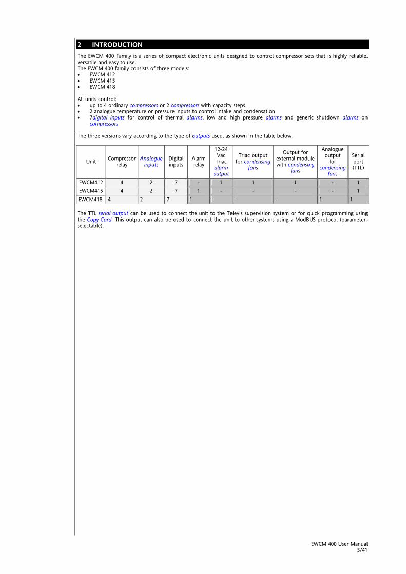
2 INTRODUCTION The EWCM 400 Family is a series of compact electronic units designed to control compressor sets that is highly reliable, versatile and easy to use. The EWCM 400 family consists of three models: • EWCM 412 • EWCM 415 • EWCM 418 All units control: • up to 4 ordinary compressors or 2 compressors with capacity steps • 2 analogue temperature or pressure inputs to control intake and condensation • 7digital inputs for control of thermal alarms, low and high pressure alarms and generic shutdown alarms on
compressors. The three versions vary according to the type of outputs used, as shown in the table below.
Unit Compressor relay
Analogue inputs
Digital inputs
Alarm relay
12-24 Vac Triac alarm output
Triac output for condensing
fans
Output for external module with condensing
fans
Analogue output
for condensing
fans
Serial port (TTL)
EWCM412 4 2 7 - 1 1 1 - 1 EWCM415 4 2 7 1 - - - - 1 EWCM418 4 2 7 1 - - - 1 1 The TTL serial output can be used to connect the unit to the Televis supervision system or for quick programming using the Copy Card. This output can also be used to connect the unit to other systems using a ModBUS protocol (parameter-selectable).
EWCM 400 User Manual 6/41
3 INSTALLATION Before proceeding, make sure that you have connected the power supply using a suitable external transformer. Cards must be connected as follows: • do not apply loads to the outputs exceeding those indicated in this specification; • when connecting the loads, carefully observe the wiring diagrams; • always use separate cables for high and low voltage loads.
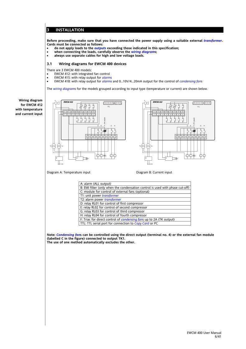
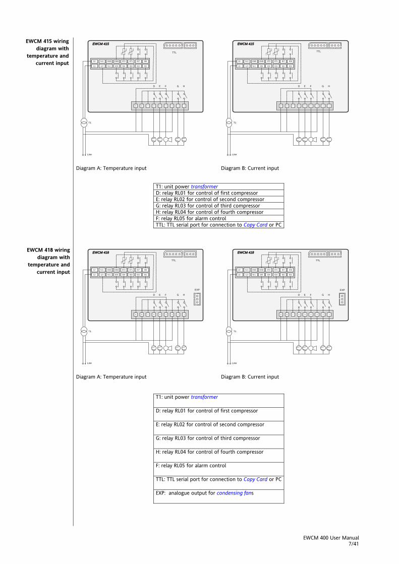
3.1 Wiring diagrams for EWCM 400 devices There are 3 EWCM 400 models: • EWCM 412: with integrated fan control • EWCM 415: with relay output for alarms • EWCM 418: with relay output for alarms and 0�10V/4�20mA output for the control of condensing fans The wiring diagrams for the models grouped according to input type (temperature or current) are shown below.
Diagram A: Temperature input Diagram B: Current input
A: alarm (ALL output) B: EMI filter (only when the condensation control is used with phase cut-off) C: module for control of external fans (optional) T1: unit power transformer T2: alarm power transformer D: relay RL01 for control of first compressor E: relay RL02 for control of second compressor G: relay RL03 for control of third compressor H: relay RL04 for control of fourth compressor F: Triac for direct control of condensing fans up to 2A (TK output) TTL: TTL serial port for connection to Copy Card or PC
Note: Condensing fans can be controlled using the direct output (terminal no. 4) or the external fan module (labelled C in the figure) connected to output TK1. The use of one method automatically excludes the other.
Wiring diagram for EWCM 412
with temperature and current input
123456789
ALL GND
TK1
GND
ID5
ST2
ID4
ST1
ID3
ID7
ID2
ID6
ID1
B
Line
C
A
D E F G H
T2 T1
EWCM 412
12~
12~ 12=
(TK
out
put)
TTL
<IMG INFO>
123456789
ALL GND
TK1
GND
ID5
ST2
ID4
ST1
ID3
ID7
ID2
ID6
ID1
B
Line
C
A
D E F G H
T2 T1
EWCM 412
12~
12~ 12=
TTL
(TK
out
put)
<IMG INFO>
EWCM 400 User Manual 7/41
Diagram A: Temperature input Diagram B: Current input
T1: unit power transformer D: relay RL01 for control of first compressor E: relay RL02 for control of second compressor G: relay RL03 for control of third compressor H: relay RL04 for control of fourth compressor F: relay RL05 for alarm control TTL: TTL serial port for connection to Copy Card or PC
Diagram A: Temperature input Diagram B: Current input
EWCM 415 wiring diagram with
temperature and current input
EWCM 418 wiring diagram with
temperature and current input
T1: unit power transformer D: relay RL01 for control of first compressor E: relay RL02 for control of second compressor G: relay RL03 for control of third compressor H: relay RL04 for control of fourth compressor F: relay RL05 for alarm control TTL: TTL serial port for connection to Copy Card or PC EXP: analogue output for condensing fans
123456789
12~
12~
N.C.
12=
GND
N.C.
GND
ID5
ST2
ID4
ST1
ID3
ID7
ID2
ID6
ID1
Line
D E F G H
T1
EWCM 415
TTL
<IMG INFO>
123456789
12~
12~
N.C.
12=
GND
N.C.
GND
ID5
ST2
ID4
ST1
ID3
ID7
ID2
ID6
ID1
Line
D E F G H
T1
EWCM 415
TTL
<IMG INFO>
123456789
12~
12~
N.C.
12=
GND
N.C.
GND
ID5
ST2
ID4
ST1
ID3
ID7
ID2
ID6
ID1
Line
D E F G H
T1
EWCM 418
TTL
EXP
<IMG INFO>
123456789
12~
12~
N.C.
12=
GND
N.C.
GND
ID5
ST2
ID4
ST1
ID3
ID7
ID2
ID6
ID1
Line
D E F G H
T1
EWCM 418
EXP
TTL
<IMG INFO>
EWCM 400 User Manual 8/41
The unit is configured according to the values of the parameters for the inputs and outputs.
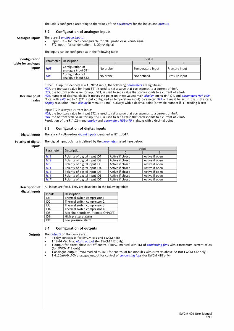
3.2 Configuration of analogue inputs There are 2 analogue inputs: • input ST1 � for inlet - configurable for NTC probe or 4...20mA signal. • ST2 input - for condensation - 4...20mA signal. The inputs can be configured as in the following table.
Value Parameter Description 0 1 2
H05 Configuration of analogue input ST1 No probe Temperature input Pressure input
H06 Configuration of analogue input ST2 No probe Not defined Pressure input
If the ST1 input is defined as a 4...20mA input, the following parameters are significant: H07, the top scale value for input ST1, is used to set a value that corresponds to a current of 4mA H09, the bottom scale value for input ST1, is used to set a value that corresponds to a current of 20mA H29, number of decimal places; it moves the point on these values; main display, menu tP / t01, and parameters H07-H09. Note: with H05 set to 1 (ST1 input configured as temperature input) parameter H29 = 1 must be set. If this is the case, display resolution (main display in menu tP / t01) is always with a decimal point (or whole number if �F� reading is set) Input ST2 is always a current input: H08, the top scale value for input ST2, is used to set a value that corresponds to a current of 4mA H10, the bottom scale value for input ST2, is used to set a value that corresponds to a current of 20mA Resolution of the P / t02 menu display and parameters H08-H10 is always with a decimal point.
3.3 Configuration of digital inputs There are 7 voltage-free digital inputs identified as ID1�.ID17. The digital input polarity is defined by the parameters listed here below:
Value Parameter Description 0 1 H11 Polarity of digital input ID1 Active if closed Active if open H12 Polarity of digital input ID2 Active if closed Active if open H13 Polarity of digital input ID3 Active if closed Active if open H14 Polarity of digital input ID4 Active if closed Active if open H15 Polarity of digital input ID5 Active if closed Active if open H16 Polarity of digital input ID6 Active if closed Active if open H17 Polarity of digital input ID7 Active if closed Active if open
All inputs are fixed. They are described in the following table: Inputs Description ID1 Thermal switch compressor 1 ID2 Thermal switch compressor 2 ID3 Thermal switch compressor 3 ID4 Thermal switch compressor 4 ID5 Machine shutdown (remote ON/OFF) ID6 High pressure alarm ID7 Low pressure alarm
3.4 Configuration of outputs The outputs on the device are: • 4 relay contacts (5 for EWCM 415 and EWCM 418) • 1 12-24 Vac Triac alarm output (for EWCM 412 only) • 1 output for direct phase cut-off control (TRIAC, marked with TK) of condensing fans with a maximum current of 2A
(for EWCM 412 only) • 1 analogue output (PWM marked as TK1) for control of fan modules with currents above 2A (for EWCM 412 only) • 1 4�20mA/0�10V analogue output for control of condensing fans (for EWCM 418 only)
Analogue inputs
Configuration table for analogue
inputs
Decimal point value
Digital inputs
Polarity of digital inputs
Description of digital inputs
Outputs
EWCM 400 User Manual 9/41
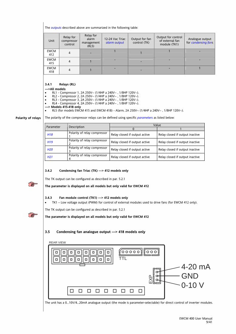
The outputs described above are summarized in the following table:
Unit Relay for
compressor control
Relay for alarm
management (RL5)
12-24 Vac Triac alarm output
Output for fan control (TK)
Output for control of external fan module (TK1)
Analogue output for condensing fans
EWCM 412 4 - 1 1 1 -
EWCM 415 4 1 - - - -
EWCM 418 4 1 - - - 1
3.4.1 Relays (RL) --->All models • RL1 - Compressor 1, 2A 250V~ (1/4HP a 240V~ , 1/8HP 120V~). • RL2 - Compressor 2, 2A 250V~ (1/4HP a 240V~ , 1/8HP 120V~). • RL3 - Compressor 3, 2A 250V~ (1/4HP a 240V~ , 1/8HP 120V~). • RL4 - Compressor 4, 2A 250V~ (1/4HP a 240V~ , 1/8HP 120V~). ---> Models 415-418 only • RL5 (for models EWCM 415 and EWCM 418) - Alarm, 2A 250V~ (1/4HP a 240V~ , 1/8HP 120V~). The polarity of the compressor relays can be defined using specific parameters as listed below:
Value Parameter Description 0 1
H18 Polarity of relay compressor 1 Relay closed if output active Relay closed if output inactive
H19 Polarity of relay compressor 2 Relay closed if output active Relay closed if output inactive
H20 Polarity of relay compressor 3 Relay closed if output active Relay closed if output inactive
H21 Polarity of relay compressor 4 Relay closed if output active Relay closed if output inactive
3.4.2 Condensing fan Triac (TK) ---> 412 models only The TK output can be configured as described in par. 5.2.1 The parameter is displayed on all models but only valid for EWCM 412
3.4.3 Fan module control (TK1) ---> 412 models only • TK1 � Low voltage output (PWM) for control of external modules used to drive fans (for EWCM 412 only). The TK output can be configured as described in par. 5.2.1 The parameter is displayed on all models but only valid for EWCM 412
3.5 Condensing fan analogue output ---> 418 models only
The unit has a 0�10V/4�20mA analogue output (the mode is parameter-selectable) for direct control of inverter modules.
Polarity of relays
TTL
EX
P
REAR VIEW
4-20 mAGND0-10 V
EWCM 400 User Manual 10/41
3.6 Serial output The unit has an asynchronous serial output that enables the unit to be connected to a PC via an interface module. Parameter H22 is used to select the type of communication protocol • H22 = 0 Televis protocol • H22 = 1 Modbus protocol
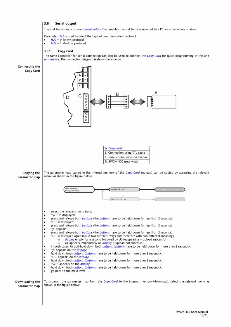
3.6.1 Copy Card The same connector for serial connection can also be used to connect the Copy Card for quick programming of the unit parameters. The connection diagram is shown here below:
A: Copy card B: Connection using TTL cable C: serial communication channel D: EWCM 400 (rear view)
The parameter map stored in the internal memory of the Copy Card (upload) can be copied by accessing the relevant menu, as shown in the figure below:
• select the relevant menu item; • �SCF� is displayed; • press and release both buttons (the buttons have to be held down for less than 2 seconds); • �UL� is displayed; • press and release both buttons (the buttons have to be held down for less than 2 seconds); • �y� appears; • press and release both buttons (the buttons have to be held down for less than 2 seconds); • �UL� is displayed again but in two different ways and therefore with two different meanings:
o display empty for a second followed by UL reappearing = upload successful o UL appears immediately on display = upload not successful
• in both cases, to quit hold down both buttons (buttons have to be held down for more than 2 seconds); • �y� appears on the display; • hold down both buttons (buttons have to be held down for more than 2 seconds); • �UL� appears on the display; • hold down both buttons (buttons have to be held down for more than 2 seconds); • �SCF� appears on the display; • hold down both buttons (buttons have to be held down for more than 2 seconds); • go back to the main level To program the parameter map from the Copy Card to the internal memory (download), select the relevant menu as shown in the figure below:
Connecting the Copy Card
Copying the parameter map
Downloading the parameter map
B ACD
<IMG INFO> 340,05 182,35 0 2 42,55 0 -1 325,3 175,5

EWCM 400 User Manual 11/41
• select the relevant item in the SCF menu; • press and release both buttons (the buttons have to be pressed for less than 2 seconds); • �UL� appears on the display; • press and release the down button; • �dL� appears on the display; • press and release both buttons (the buttons have to be pressed for less than 2 seconds); • �y� appears on the display; • press and release both buttons (the buttons have to be pressed for less than 2 seconds); • downloading can be effected in 2 different ways:
o when downloading, the display is unsteady for 1 second and �Occ� then appears on the display; o If downloading fails, �Err� immediately appears on the display;
• in both cases, to quit hold down both buttons (buttons have to be held down for more than 2 seconds); • �y� appears on the display; • hold down both buttons (buttons have to be held down for more than 2 seconds); • �dL� appears on the display; • hold down both buttons (buttons have to be held down for more than 2 seconds); • �SCF� appears on the display; • hold down both buttons (buttons have to be held down for more than 2 seconds); • go back to the main level • once the operation has been completed, the Copy Card must be disconnected; • after modifying the configuration parameters, we strongly recommend that you switch the instrument off and on
again. If the operation is successful, Occ appears on the display. After completing the operation, the Copy Card must be disconnected. We strongly recommend that you switch the unit off and on again each time configuration parameters are changed. Once downloading or uploading has been confirmed, select �y� to continue or �n� to cancel the operation.
3.7 Physical quantities and units of measurement
3.7.1 Units of measurement Control temperature can be displayed in: • °C with decimal point* • °F without decimal point* *See paragraph 5.2 Setting the decimal point To convert from one unit of measurement to the other: °F=°C x 9/5 + 32 The unit of measurement can be set using parameter H33: H33 Unit of
measurement 0 Degrees °C 1 Degrees °F
EWCM 400 User Manual 12/41
<IMG INFO> 56 43 1 2 51 -21 -1 46,5
<IMG INFO> 56 41 1 2 51 -20 1
<IMG INFO> 56 72 1 2 51 -36,1 -1 46,5 62,25
<IMG INFO> 56 72 1 2 51 -36,1 -1 46,5 62,25
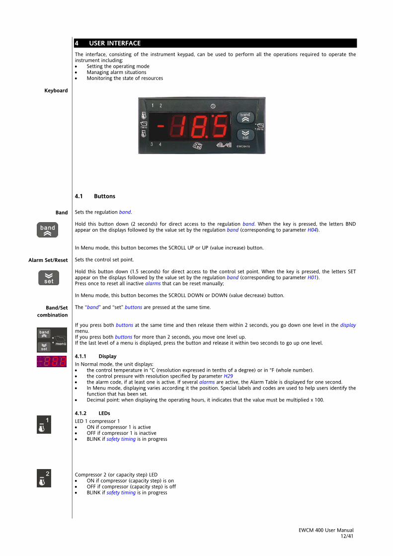
4 USER INTERFACE The interface, consisting of the instrument keypad, can be used to perform all the operations required to operate the instrument including: • Setting the operating mode • Managing alarm situations • Monitoring the state of resources
4.1 Buttons Sets the regulation band. Hold this button down (2 seconds) for direct access to the regulation band. When the key is pressed, the letters BND appear on the displays followed by the value set by the regulation band (corresponding to parameter H04). In Menu mode, this button becomes the SCROLL UP or UP (value increase) button. Sets the control set point. Hold this button down (1.5 seconds) for direct access to the control set point. When the key is pressed, the letters SET appear on the displays followed by the value set by the regulation band (corresponding to parameter H01). Press once to reset all inactive alarms that can be reset manually; In Menu mode, this button becomes the SCROLL DOWN or DOWN (value decrease) button. The �band� and �set� buttons are pressed at the same time. If you press both buttons at the same time and then release them within 2 seconds, you go down one level in the display menu. If you press both buttons for more than 2 seconds, you move one level up. If the last level of a menu is displayed, press the button and release it within two seconds to go up one level.
4.1.1 Display In Normal mode, the unit displays: • the control temperature in °C (resolution expressed in tenths of a degree) or in °F (whole number). • the control pressure with resolution specified by parameter H29 • the alarm code, if at least one is active. If several alarms are active, the Alarm Table is displayed for one second. • In Menu mode, displaying varies according it the position. Special labels and codes are used to help users identify the
function that has been set. • Decimal point: when displaying the operating hours, it indicates that the value must be multiplied x 100.
4.1.2 LEDs LED 1 compressor 1 • ON if compressor 1 is active • OFF if compressor 1 is inactive • BLINK if safety timing is in progress Compressor 2 (or capacity step) LED • ON if compressor (capacity step) is on • OFF if compressor (capacity step) is off • BLINK if safety timing is in progress
Keyboard
Band
Alarm Set/Reset
Band/Set combination
<IMG INFO> 283,35 140,65 0 2 71 0 -1 269,25 133,5

EWCM 400 User Manual 13/41
<IMG INFO> 56 59 1 2 51 -29 -1 46,5 49,5
<IMG INFO> 56 72 1 2 51 -36,1 -1 46,5 62,25
<IMG INFO> 56 72 1 2 51 -36,1 -1 46,5 62,25
<IMG INFO> 56 55 1 2 51 -28 -1 46,5 45,75
Compressor 3 (or capacity step) LED • ON if compressor (capacity step) is on • OFF if compressor (capacity step) is off • BLINK if safety timing is in progress Compressor 4 (or capacity step) LED • ON if compressor (capacity step) is on • OFF if compressor (capacity step) is off • BLINK if safety timing is in progress Menu LED • BLINK if the menu levels are being displayed • OFF in Normal display mode STAND-BY LED • ON if the unit is operating • OFF if the unit is in STAND-BY mode
4.2 Device status The EWCM 400 device status can be selected
• using the digital input • using the function programming menu
The sequence of commands to be performed to modify EWCM 400 status using the keyboard menu is shown below:
1. press and release both buttons (within 2 seconds) to access the menu 2. go to �StA� in the menu using the SCROLL DOWN and SCROLL UP buttons; 3. press and release both buttons (within 2 seconds); 4. �On� appears on the display 5. select the status (�On�, �Off�) using the SCROLL DOWN and SCROLL UP buttons; 6. once the required status has been displayed, press and release both buttons (within 2 seconds): 7. the STAND-BY LED goes on or off according to the status that has been selected. 8. press and release both buttons (the buttons have to be pressed for less than 2 seconds) to display �StA� and
reset the status as in point 2; 9. hold both buttons down (buttons have to be held down for more than 2 seconds) to quit the menu;
Attention: when the STAND-BY LED is turned off, the instrument does not regulate the outputs. In this phase, the temperature/pressure values detected by the device are displayed.
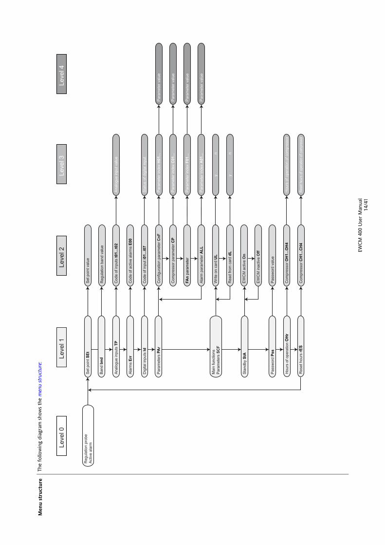
4.3 Programming parameters and displaying unit status: menu levels Access to the parameters and machine inputs is structured in sublevels that can be accessed by pressing the "mode" and "on-off" buttons simultaneously (see above). Each menu level is identified by a mnemonic code which appears on the display. It is structured as shown in the following diagram (see following page):
Modifying status of On-Off device
EWCM attivo On
EWCM non attivo Off
Stand-by StA
<IMG INFO> 340,1 53,4 0 2
EWCM
400
Use
r M
anua
l 14
/41
The
follo
win
g di
agra
m s
how
s th
e m
enu
stru
ctur
e:
Men
u st
ruct
ure
<I
MG
INFO
>

EWCM 400 User Manual 15/41
EWCM 400 User Manual 16/41
5 SYSTEM CONFIGURATION This section explains how to configure the parameters for the different loads according to the type of system to be controlled.
5.1 Compressors EWCM 400 can control systems with a cooling circuit comprising a maximum of 4 compressors Capacity steps, when present, are considered compressors. Each compressors is driven by a device relay. Compressors are switched on or off according to the temperatures measured and the temperature control functions set (see paragraph "Control of compressors � temperature controller").
5.1.1 Compressor configuration The compressors must always be connected to outputs RL1-RL4. Parameter H30 selects the number of compressors in the system. The polarity of the compressor outputs can be selected using parameters H18 and H21: • 0= Relay ON if compressor/capacity step ON • 1= Relay ON if compressor/capacity step OFF
5.1.2 Compressor start/stop sequence The order in which the compressors are started can be changed with parameter H31. This parameter determines the start sequence of compressors as described below. • H31 = 0 Compressors are started according to operating hours (balancing of operating hours). • H31 = 1 The first compressor to be started is the one with the lowest value (followed by the compressor (or capacity
step) with the highest value (fixed sequence). If H31 = 0, the first compressor to be started is the one with the lowest number of operating hours unless: • an active compressor block alarm is present (see Alarms table). • safety timing in progress. If H31 = 0, the first compressor to be switched off is the one with the highest number of operating hours. If H31 = 1: • the compressor (capacity step) with the highest value is only started if the compressor with the lowest value is
already running (except when the compressor with the lowest value is in alarm mode). • The compressor with the lowest value is only switched off if all the compressors with the highest values are already
off.
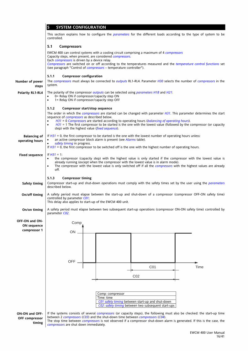
5.1.3 Compressor timing Compressor start-up and shut-down operations must comply with the safety times set by the user using the parameters described below. A safety period must elapse between the start-up and shut-down of a compressor (compressor OFF-ON safety time) controlled by parameter C01; This delay also applies to start-up of the EWCM 400 unit. A safety period must elapse between two subsequent start-up operations (compressor ON-ON safety time) controlled by parameter C02.
Comp: compressor Time: time C01 safety timing between start-up and shut-down C02: safety timing between two subsequent start-ups
If the systems consists of several compressors (or capacity steps), the following must also be checked: the start-up time between 2 compressors (C03) and the shut-down time between compressors (C04). The stop time between compressors is not observed if a compressor shut-down alarm is generated. If this is the case, the compressors are shut down immediately.
Number of power steps
Polarity RL1-RL4
Balancing of operating hours
Fixed sequence
Safety timing
On/off timing
On/on timing
OFF-ON and ON-ON sequence compressor 1
ON-ON and OFF-OFF compressor
timing
Time
ON
Comp
OFF
C02
C01
IMG INFO
EWCM 400 User Manual 17/41
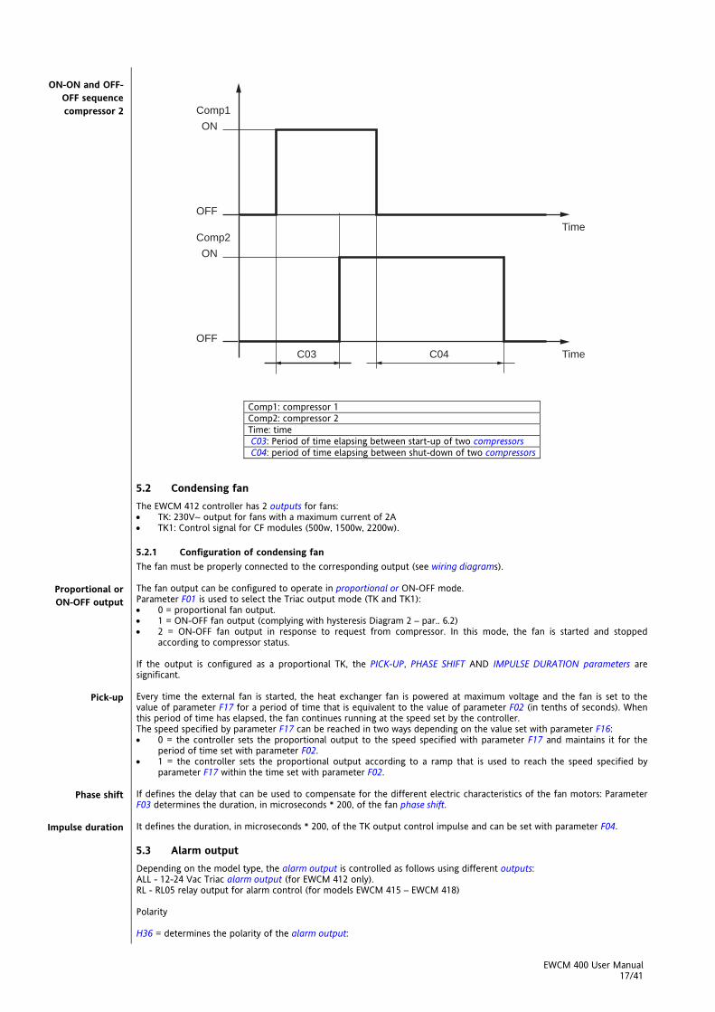
Comp1: compressor 1 Comp2: compressor 2 Time: time C03: Period of time elapsing between start-up of two compressors C04: period of time elapsing between shut-down of two compressors
5.2 Condensing fan The EWCM 412 controller has 2 outputs for fans: • TK: 230V~ output for fans with a maximum current of 2A • TK1: Control signal for CF modules (500w, 1500w, 2200w).
5.2.1 Configuration of condensing fan The fan must be properly connected to the corresponding output (see wiring diagrams). The fan output can be configured to operate in proportional or ON-OFF mode. Parameter F01 is used to select the Triac output mode (TK and TK1): • 0 = proportional fan output. • 1 = ON-OFF fan output (complying with hysteresis Diagram 2 � par.. 6.2) • 2 = ON-OFF fan output in response to request from compressor. In this mode, the fan is started and stopped
according to compressor status. If the output is configured as a proportional TK, the PICK-UP, PHASE SHIFT AND IMPULSE DURATION parameters are significant. Every time the external fan is started, the heat exchanger fan is powered at maximum voltage and the fan is set to the value of parameter F17 for a period of time that is equivalent to the value of parameter F02 (in tenths of seconds). When this period of time has elapsed, the fan continues running at the speed set by the controller. The speed specified by parameter F17 can be reached in two ways depending on the value set with parameter F16: • 0 = the controller sets the proportional output to the speed specified with parameter F17 and maintains it for the
period of time set with parameter F02. • 1 = the controller sets the proportional output according to a ramp that is used to reach the speed specified by
parameter F17 within the time set with parameter F02. If defines the delay that can be used to compensate for the different electric characteristics of the fan motors: Parameter F03 determines the duration, in microseconds * 200, of the fan phase shift. It defines the duration, in microseconds * 200, of the TK output control impulse and can be set with parameter F04.
5.3 Alarm output Depending on the model type, the alarm output is controlled as follows using different outputs: ALL - 12-24 Vac Triac alarm output (for EWCM 412 only). RL - RL05 relay output for alarm control (for models EWCM 415 � EWCM 418) Polarity H36 = determines the polarity of the alarm output:
ON-ON and OFF-OFF sequence compressor 2
Proportional or ON-OFF output
Pick-up
Phase shift
Impulse duration
Time
Time
ON
ON
Comp2
Comp1
OFF
OFF
C03 C04
<IMG INFO>
EWCM 400 User Manual 18/41
IMG INFO
0 = the output is active (contact closed) when an alarm is active and the machine is off 1 = the contact is open with the same conditions Alarm OFF H38 = establishes whether the alarm is active in Standby mode 0 = inactive alarm output in Stand-by mode 1 = active alarm output in Stand-by mode The power supply of the alarm output must be kept separate from the power supply of the controller.
EWCM 400 User Manual 19/41
6 TEMPERATURE CONTROL FUNCTIONS Once the EWCM 400 has been configured, it is ready to control the loads according to the temperature and pressure conditions measured by the probes and the temperature control functions defined by special parameters. The following operating modes are available: • cooling/direct. • heating/inverse. • stand-by. The operating mode is selected using parameter H37: 0= cooling/direct function. 1= heating/inverse function. Stand-by: in this mode the unit does not perform temperature control functions and all alarms remain active. The section below describes the menu items:
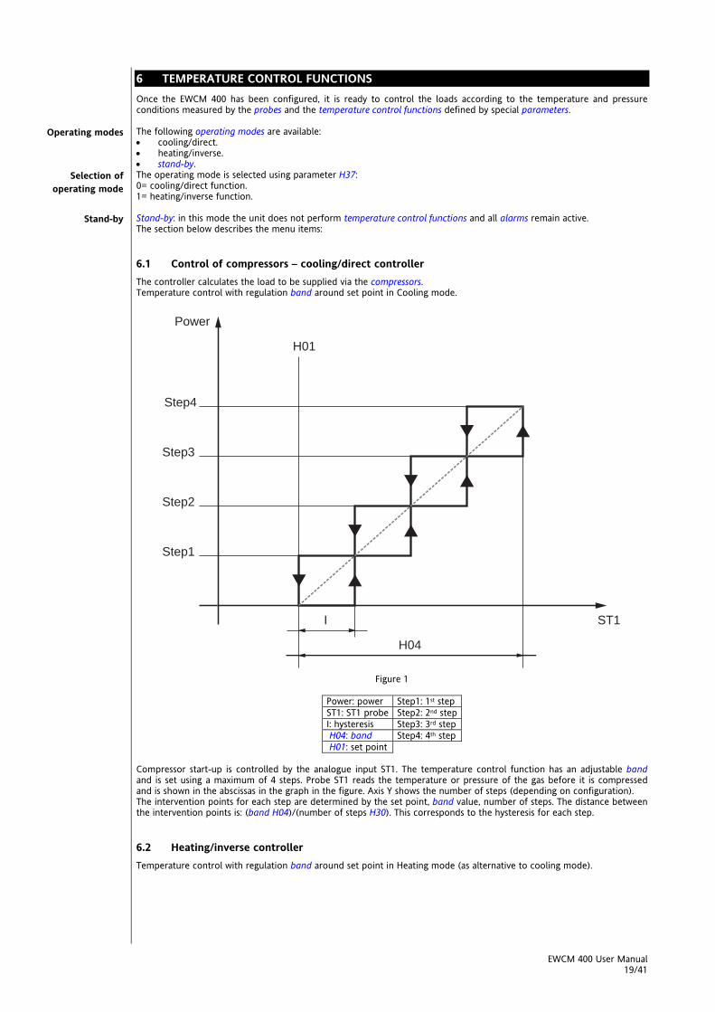
6.1 Control of compressors � cooling/direct controller The controller calculates the load to be supplied via the compressors. Temperature control with regulation band around set point in Cooling mode.
Figure 1
Power: power Step1: 1st step ST1: ST1 probe Step2: 2nd step I: hysteresis Step3: 3rd step H04: band Step4: 4th step H01: set point
Compressor start-up is controlled by the analogue input ST1. The temperature control function has an adjustable band and is set using a maximum of 4 steps. Probe ST1 reads the temperature or pressure of the gas before it is compressed and is shown in the abscissas in the graph in the figure. Axis Y shows the number of steps (depending on configuration). The intervention points for each step are determined by the set point, band value, number of steps. The distance between the intervention points is: (band H04)/(number of steps H30). This corresponds to the hysteresis for each step.
6.2 Heating/inverse controller Temperature control with regulation band around set point in Heating mode (as alternative to cooling mode).
Operating modes
Selection of operating mode
Stand-by
Power
ST1
Step2
Step1
Step3
Step4
H01
H04
I
<IMG INFO>

EWCM 400 User Manual 20/41
Power: power Step1: 1st step ST1: ST1 probe Step2: 2nd step I: hysteresis Step3: 3rd step H04: band Step4: 4th step H01: set point
Power
ST1
Step2
Step1
Step3
Step4
H01
H04
I
<IMG INFO>
EWCM 400 User Manual 21/41
6.3 Condensing fan control Control of the condensing fan depends on condensation pressure. The controller is active if ST2 is present; if not, the fan goes ON and OFF in response to the compressors. Fan control may be carried out independently of the compressor or when a request is received from the compressor; The operating mode is set with parameter F05:
Value Parameter 0 1
F05 If compressor is off, the fan is off Condensation control is carried out independently of compressor
If the proportional control requests fan cut-off, this cut-off may be excluded for a period of time equal to F12 from when the compressor is turned on. If the controller requests cut-off during this period, the fan will run at minimum speed. The fan control output may be: Outputs Model Description of output signal Triac output for condensing fans EWCM 412 Variable voltage (% value, see fan diagram) Output for condensing fan external module EWCM 412 PWM signal for external module; variable voltage (value corresponds to
voltage supplied by module) Analogue output for condensing fans EWCM 418 Analogue signal (% value, see fan diagram)
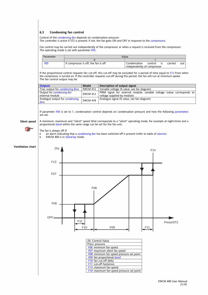
If parameter F05 is set to 1, condensation control depends on condensation pressure and how the following parameters are set: A minimum, maximum and "silent" speed (that corresponds to a "silent" operating mode, for example at night-time) and a proportional band within the same range can be set for the fan unit. The fan is always off if: • an alarm indicating that a condensing fan has been switched off is present (refer to table of alarms). • EWCM 400 is in Stand-by mode.
(%) :Control Value Press: pressure F06: minimum fan speed F07: maximum silent fan speed F08: minimum fan speed pressure set point F09: fan proportional band F10: fan cut-off delta F11: cut-off hysteresis F13: maximum fan speed F14: maximum fan speed pressure set point
Silent speed
Ventilation chart
Press/ST2F11
F10 F09
F08
F14
F11
(%)
F13
F07
F06
OFF
IMG INFO
EWCM 400 User Manual 22/41
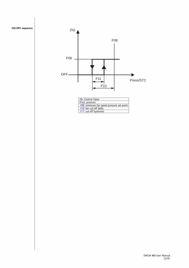
(%) :Control Value Press: pressure F08: minimum fan speed pressure set point F10: fan cut-off delta F11: cut-off hysteresis
ON-OFF sequence
Press/ST2F11
F10
F08
(%)
F06
OFF
<IMG INFO>

EWCM 400 User Manual 23/41
<IMG INFO>
7 FUNCTIONS
7.1 Registration of working hours The unit stores in the non volatile memory the hours of operation of the 4 compressors. Internal resolution is in minutes. To display the values, it is necessary to access the related menu labeled Ohr (see menu tree). The integer value is displayed for values below 999, while the hours/100 value along with the decimal point is displayed for values above 999. 1234 hours are displayed as follows:
To reset the hours, it is necessary to access the related menu labeled rES (see menu tree). In the event of power failure, the last fraction of hour recorded is set to 0, thus the duration is rounded by default:
35.48 35

8 PARAMETERS Parameters can be set to make the EWCM 400 fully configurable. Parameters can be changed using: • keyboard • Copy Card • PC (using special connection and software)
8.1 Description of parameters All the parameters are described in detail in the following sections and divided into categories.
8.1.1 Configuration parameters These parameters define the characteristics of the machine. If one or more parameters in this category is changed, the controller must be turned off and on again after the change is made in order to operate correctly. Set point Used to set the control set point. Maximum set point Used to set the maximum set point limit. Minimum set point Used to set the minimum set point limit. Regulation band Sets the regulation band. ST1 configuration Used to configure analogue input ST1. 0= No probe 1= Temperature input 2= Pressure input (4-20mA signal) ST2 configuration 0= No probe 1= N.A. 2= Pressure input (4-20mA signal) Pressure top scale value ST1 Pressure top scale value ST2 Used to set a value that corresponds to a current of 4mA. Pressure bottom scale value ST1 Pressure bottom scale value ST2 Used to set a value that corresponds to a current of 20mA. Polarity ID1 Polarity ID2 Polarity ID3 Polarity ID4 Polarity ID5 Polarity ID6 Polarity ID7 0= Active with closed contact 1= Active with open contact Configuration of polarity for compressor 1 Configuration of polarity for compressor 2 Configuration of polarity for compressor 3 Configuration of polarity for compressor 4 0= Closed relay for active output 1= Closed relay for inactive output Configuration of serial protocol 0= Televis protocol 1= Modbus protocol Offset ST1 Offset ST2 This parameter can be used to compensate for the error that may occur between the temperature (or pressure) reading and the actual value. Mains frequency 0= mains frequency: 50 Hz 1= mains frequency: 60 Hz Family serial address Device serial address Used to select the serial address. Both normally set to 0. User password Can be used to enter the password required to access second level parameters. 0= Password deactivated (all parameters can be viewed) >0= Password activated Position of decimal point 0= decimal point not present 1= decimal point after first decimal digit (i.e. 13.5) 2= decimal point after second decimal digit (i.e. 1.35) Number of compressors 1= 1 compressor 2= 2 compressors (or 2 steps) 3= 3 compressors (or 3 steps) 4= 4 compressors (or 4 steps)
H01
H02
H03
H04
H05
H06
H07 H08
H09 H10
H11 H12 H13 H14 H15 H16 H17
H18 H19 H20 H21
H22
H23 H24
H25
H26 H27
H28
H29
H30
EWCM 400 User Manual 25/41
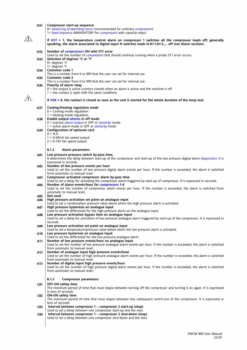
Compressor start-up sequence 0= balancing of operating hours (recommended for ordinary compressors) 1= fixed sequence (MANDATORY for compressors with capacity steps) If H31 = 1, the temperature control alarm on compressor 1 switches all the compressor loads off; generally speaking, the alarm associated to digital input N switches loads N,N+1,N+2,� off (see Alarm section). Number of compressors ON with ST1 error Used to set the number of compressors that should continue running when a probe ST1 error occurs. Selection of degrees °C or °F 0= degrees °C 1= degrees °F Customer code 1 This is a number from 0 to 999 that the user can set for internal use. Customer code 2 This is a number from 0 to 999 that the user can set for internal use. Polarity of alarm relay 0 = the output is active (contact closed) when an alarm is active and the machine is off 1 = the contact is open with the same conditions If H36 = 0, the contact is closed as soon as the unit is started for the whole duration of the lamp test. Cooling/Heating regulation mode 0 = Cooling mode regulation 1 = Heating mode regulation Enable output alarms in off mode 0 = inactive alarm output in OFF or stand-by mode 1 = active alarm mode in OFF or stand-by mode Configuration of optional card 0 = N.A. 1 = 4-20mA fan speed output 2 = 0-10V fan speed output
8.1.2 Alarm parameters Low pressure pressure switch by-pass time. It determines the delay between start-up of the compressor and start-up of the low pressure digital alarm diagnostics. It is expressed in seconds. Number of low pressure events per hour Used to set the number of low pressure digital alarm events per hour. If the number is exceeded, the alarm is switched from automatic to manual reset. Compressor activated compressor alarm by-pass time Used to set a delay for activating the compressor alarm triggered by start-up of compressor. It is expressed in seconds. Number of alarm events/hour for compressors 1-4 Used to set the number of compressor alarm events per hour. If the number is exceeded, the alarm is switched from automatic to manual reset. Not used High pressure activation set point on analogue input Used to set a condensation pressure value above which the high pressure alarm is activated. High pressure hysteresis on analogue input Used to set the differential for the high pressure alarm on the analogue input. Low pressure activation bypass time on analogue input Used to set a delay for activation of low pressure analogue alarm triggered by start-up of the compressor. It is expressed in seconds. Low pressure activation set point on analogue input Used to set a temperature/pressure value below which the low pressure alarm is activated. Low pressure hysteresis on analogue input Used to set the differential for the low pressure analogue alarm. Number of low pressure events/hour on analogue input Used to set the number of low pressure analogue alarm events per hour. If the number is exceeded, the alarm is switched from automatic to manual reset. Number of analogue input high pressure events/hour Used to set the number of high pressure analogue alarm events per hour. If the number is exceeded, the alarm is switched from automatic to manual reset. Number of digital input high pressure events/hour Used to set the number of high pressure digital alarm events per hour. If the number is exceeded, the alarm is switched from automatic to manual reset.
8.1.3 Compressor parameters OFF-ON safety time The minimum period of time that must elapse between turning off the compressor and turning it on again. It is expressed in tens of seconds. ON-ON safety time The minimum period of time that must elapse between two subsequent switch-ons of the compressor. It is expressed in tens of seconds. Interval between compressor 1 � compressor 2 start-up (step) Used to set a delay between one compressor start-up and the next. Interval between compressor 1 � compressor 2 shut-down (step) Used to set a delay between one compressor shut-down and the next.
H31
H32
H33
H34
H35
H36
H37
H38
H39
A01
A02
A03
A04
A05 A06
A07
A08
A09
A10
A11
A12
A13
C01
C02
C03
C04

EWCM 400 User Manual 26/41
8.1.4 Fan parameters Fan output configuration 0 = proportional TK output 1 = ON-OFF TK output (without capacity step) 2 = ON-OFF TK output in response to request from compressor Fan pick-up time Time the fan runs at maximum speed (F17) after a restart (pick-up). Fan phase shift Used to adapt output to different types of fans. Duration of Triac activation impulse Used to vary the length of the Triac impulse. If external DRV control boards are used, set F04 = 30. Operation in response to compressor request 0 = if all the compressors are off and fan is off 1 = if the condensation control is carried out independently from the compressors Minimum speed Minimum value for proportional regulation of fans. It is expressed as a percentage, from 0 to 100%, of the maximum permitted voltage. Silent speed Maximum value for proportional regulation of fans. It is expressed as a percentage, from 0 to 100%, of the maximum permitted voltage. Minimum fan speed pressure set point Pressure condensation value that corresponds to the minimum speed. Proportional band Pressure differential corresponding to a change from minimum to maximum fan speed. Cut-off differential Condensation pressure differential within which fan continues at minimum speed. Cut-off hysteresis Condensation pressure differential for fan shut-down. Cut-off bypass time Used to select a delay between activation of the cut-off function and fan start-up. It is expressed in seconds. Maximum speed Used to set a speed step for a specific pressure value. Maximum fan speed pressure set point Condensation pressure value that corresponds to the fan speed set with parameter F13. Pre-ventilation Used to set a pre-ventilation time before compressor start-up. Way to reach maximum pick-up speed Specifies how to reach the maximum pick-up speed (F17): 0 = maximum speed is reached immediately 1 = maximum speed is reached proportionally at the end of the time set for parameter F02 Maximum pickup speed Used to set the maximum pick-up speed (as a percentage).
8.2 Table of parameters The following table summarizes all the EWCM 400 parameters.
CONFIGURATION PARAMETERS* Par. Description Value Limits Unit H01 Set point 45 H03 ÷ H02 °C--kPa*10 H02 Maximum set point 700 H03 ÷ H09 °C/10--kPa*10 H03 Minimum set point -100 H07 ÷ H02 °C/10--kPa*10 H04 Regulation band 20 0 ÷ 900 °C/kPa*10 H05 ST1 configuration 2 0 ÷ 2 Num H06 ST2 configuration 2 0 ÷ 2 Num H07 Pressure top scale value ST1 -100 -99.9 ÷ H09 ** Num ** H08 Pressure top scale value ST2 0.0 -99.9 ÷ H10 kPa*100 H09 Pressure bottom scale value ST1 700 H07 ÷ 999 ** Num ** H10 Pressure bottom scale value ST2 30.0 H08 ÷ 99.9 kPa*100 H11 Polarity ID1 0 0 ÷ 1 Flag H12 Polarity ID2 0 0 ÷ 1 Flag H13 Polarity ID3 0 0 ÷ 1 Flag H14 Polarity ID4 0 0 ÷ 1 Flag H15 Polarity ID5 0 0 ÷ 1 Flag H16 Polarity ID6 0 0 ÷ 1 Flag H17 Polarity ID7 0 0 ÷ 1 Flag H18 Configuration of polarity compressor 1 0 0 ÷ 1 Flag H19 Configuration of polarity compressor 2 0 0 ÷ 1 Flag H20 Configuration of polarity compressor 3 0 0 ÷ 1 Flag H21 Configuration of polarity compressor 4 0 0 ÷ 1 Flag H22 Configuration of serial protocol 0 0 ÷ 1 Flag H23 Offset ST1 0 -12.7 ÷ 12.7 °C--kPa*10 H24 Offset ST2 0 -12.7 ÷ 12.7 kPa*10 H25 Mains frequency 0 0 ÷ 1 Flag H26 Family serial address 0 0 ÷ 14 Num
F01
F02
F03
F04
F05
F06
F07
F08
F09
F10
F11
F12
F13
F14
F15
F16
F17
Configuration (CNF) parameter
table

EWCM 400 User Manual 27/41
H27 Device serial address 0 0 ÷ 14 Num H28 User password *** 0 ÷ 255 Num H29 Position of decimal point 2 0 ÷ 2 Num H30 Number of compressors 4 1 ÷ 4 Num H31 Compressor start-up sequence 0 0 ÷ 1 Flag H32 Number of compressors ON with error on ST1 0 0 ÷ H30 Num H33 Selection of degrees °C or °F 0 0 ÷ 1 Flag H34 Customer code 1 0 0 ÷ 999 Num H35 Customer code 2 0 0 ÷ 999 Num H36 Polarity of alarm output 0 0 ÷ 1 Flag H37 Cooling/Heating regulation mode 0 0 ÷ 1 Flag H38 Enable output alarms in off state 1 0 ÷ 1 Flag H39 Configuration of optional board 2 0 ÷ 2 Flag
• * If the parameters in this category are changed, the controller must be turned off and then on again after the change in order to operate correctly.
• ** The range also depends on the value of parameters H29 and H33 • ***See paragraph 6.4 Password
ALARM PARAMETERS
Par. Description Value Limits Unit A01 Low pressure pressure switch bypass time from
compressor 0 0 ÷ 255 Seconds
A02 Number of low pressure events per hour 0 0 ÷ 255 Num A03 Compressor activated compressor alarm bypass time 0 0 ÷ 255 Seconds A04 Number of alarm events/hour for compressor 1-4 0 0 ÷ 255 Num A05 Not used - - - A06 High pressure activation set point on analogue input 90 0 ÷ 90.0 kPa*100 A07 High pressure hysteresis on analogue input 10 0 ÷ 25.5 kPa*100 A08 Low pressure activation bypass time on analogue input 0 0 ÷ 255 Seconds A09 Low pressure activation set point on analogue input -10 -50.0 ÷ 80.0 kPa*100 A10 Low pressure hysteresis on analogue input 10 0 ÷ 25.5 kPa*100 A11 Number of low pressure events per hour on analogue
input 0 0 ÷ 255 Num
A12 Number of high pressure events per hour on analogue input
0 0 ÷ 255 Num
A13 Number of high pressure events per hour on digital input 0 0 ÷ 255 Num
COMPRESSOR PARAMETERS Par. Description Values Limits Unit C01 ON-OFF safety time 6 0 ÷ 255 Seconds*10 C02 ON-ON safety time 6 0 ÷ 255 Seconds*10 C03 Interval between compressor 1 � compressor 2 start-up 30 0 ÷ 255 Seconds C04 Interval between compressor 1 � compressor 2 shut-down 10 0 ÷ 255 Seconds
! Fan parameters
FAN PARAMETERS Par. Description Value Limits Unit F01 Fan output mode 0 0 ÷ 3 Num F02 Fan pick-up time 50 0 ÷ 255 Seconds/10 F03 Fan phase shift 5 0 ÷ 100 % F04 Duration of Triac activation impulse 5 0 ÷ 255 µs/10 F05 Operation in response to compressor request 1 0 ÷ 1 Flag F06 Minimum speed 40 0 ÷ 100 % F07 Silent speed 90 0 ÷ 100 % F08 Minimum fan speed pressure set point 20 -50.0 ÷ 80.0 kPa*100 F09 Proportional band 20 0 ÷ 25.5 kPa*100 F10 Cut-off differential 30 0 ÷ 25.5 kPa*100 F11 Cut-off hysteresis 10 0 ÷ 25.5 kPa*100 F12 Cut-off bypass time 80 0 ÷ 255 Seconds F13 Maximum speed 100 0 ÷ 100 % F14 Maximum fan speed pressure set point 25 -50.0 ÷ 80.0 kPa*100 F15 Pre-ventilation 0 0 ÷ 255 Seconds F16 Way to reach maximum pick-up speed 0 0 ÷ 1 Flag F17 Maximum pickup speed 100 0 ÷ 100 %
Alarm (ALL) parameter table
Compressor (CP) parameter table
Fan (FAN) parameter table
EWCM 400 User Manual 28/41
<IMG INFO>
<IMG INFO>
<IMG INFO> 56,65 24 25
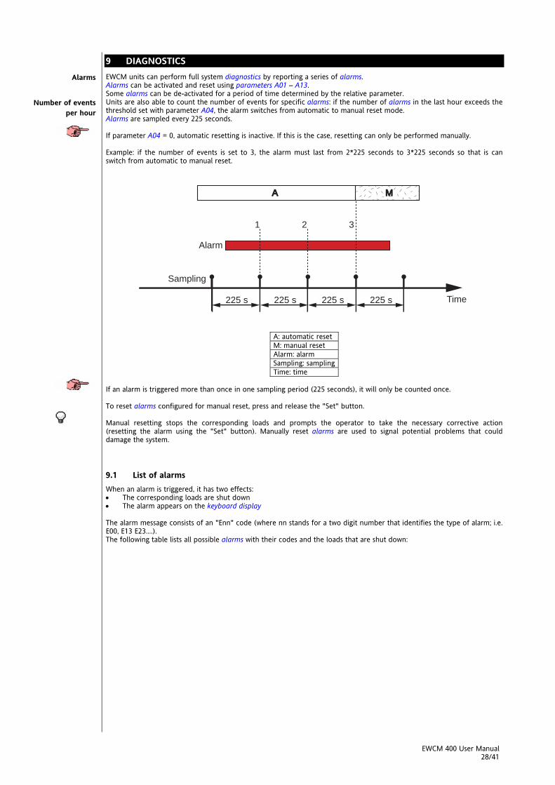
9 DIAGNOSTICS EWCM units can perform full system diagnostics by reporting a series of alarms. Alarms can be activated and reset using parameters A01 � A13. Some alarms can be de-activated for a period of time determined by the relative parameter. Units are also able to count the number of events for specific alarms: if the number of alarms in the last hour exceeds the threshold set with parameter A04, the alarm switches from automatic to manual reset mode. Alarms are sampled every 225 seconds. If parameter A04 = 0, automatic resetting is inactive. If this is the case, resetting can only be performed manually. Example: if the number of events is set to 3, the alarm must last from 2*225 seconds to 3*225 seconds so that is can switch from automatic to manual reset.
A: automatic reset M: manual reset Alarm: alarm Sampling: sampling Time: time
If an alarm is triggered more than once in one sampling period (225 seconds), it will only be counted once. To reset alarms configured for manual reset, press and release the "Set" button. Manual resetting stops the corresponding loads and prompts the operator to take the necessary corrective action (resetting the alarm using the "Set" button). Manually reset alarms are used to signal potential problems that could damage the system.
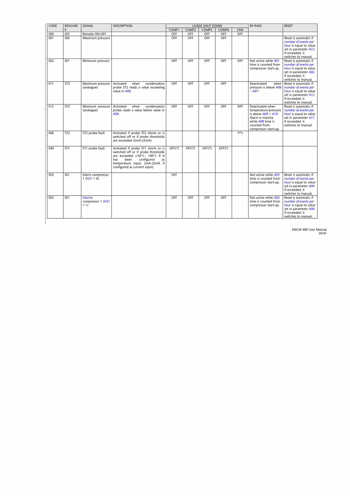
9.1 List of alarms When an alarm is triggered, it has two effects: • The corresponding loads are shut down • The alarm appears on the keyboard display The alarm message consists of an "Enn" code (where nn stands for a two digit number that identifies the type of alarm; i.e. E00, E13 E23�.). The following table lists all possible alarms with their codes and the loads that are shut down:
Alarms
Number of events per hour
225 s 225 s 225 s 225 s
1 2 3
Time
Sampling
Alarm
A M
IMG INFO
EWCM 400 User Manual 29/41
LOADS SHUT DOWN CODE RESOURCE
SIGNAL DESCRIPTION COMP1 COMP2 COMP3 COMP4 FAN
BY-PASS RESET
E00 ID5 Remote ON-OFF OFF OFF OFF OFF OFF E01 ID6 Maximum pressure OFF OFF OFF OFF Reset is automatic if
number of events per hour is equal to value set in parameter A13. If exceeded, it switches to manual.
E02 ID7 Minimum pressure
OFF OFF OFF OFF OFF Not active while A01 time is counted from compressor start-up.
Reset is automatic if number of events per hour is equal to value set in parameter A02. If exceeded, it switches to manual.
E11 ST2 Maximum pressure (analogue)
Activated when condensation probe ST2 reads a value exceeding value in A06.
OFF OFF OFF OFF Deactivated when pressure is below A06 � A07.
Reset is automatic if number of events per hour is equal to value set in parameter A12. If exceeded, it switches to manual.
E12 ST2 Minimum pressure (analogue)
Activated when condensation probe reads a value below value in A09.
OFF OFF OFF OFF OFF Deactivated when temperature/pressure is above A09 + A10. Alarm is inactive while A08 time is counted from compressor start-up.
Reset is automatic if number of events per hour is equal to value set in parameter A11. If exceeded, it switches to manual.
E06 ST2 ST2 probe fault Activated if probe ST2 shorts or is switched off or if probe thresholds are exceeded (2mA-22mA).
(**)
E40 ST1 ST1 probe fault Activated if probe ST1 shorts or is switched off or if probe thresholds are exceeded (-50°C.. 100°C if it has been configured as temperature input, 2mA-22mA if configured as current input).
OFF(*) OFF(*) OFF(*) OFF(*)
E03 ID1 Alarm compressor 1 (H31 = 0)
OFF Not active while A03 time is counted from compressor start-up.
Reset is automatic if number of events per hour is equal to value set in parameter A04. If exceeded, it switches to manual.
E03 ID1 Alarms compressor 1 (H31 = 1)
OFF OFF OFF OFF Not active while A03 time is counted from compressor start-up.
Reset is automatic if number of events per hour is equal to value set in parameter A04. If exceeded, it switches to manual.
EWCM 400 User Manual 30/41
LOADS SHUT DOWN CODE RESOURCE
SIGNAL DESCRIPTION COMP1 COMP2 COMP3 COMP4 FAN
BY-PASS RESET
E13 ID2 Alarm compressor 2 (H31 = 0)
OFF Not active while A03 time is counted from compressor start-up.
Reset is automatic if number of events per hour is equal to value set in parameter A04. If exceeded, it switches to manual.
E13 ID2 Alarm compressor 2 (H31 = 1)
OFF OFF OFF Not active while A03 time is counted from compressor start-up.
Reset is automatic if number of events per hour is equal to value set in parameter A04. If exceeded, it switches to manual.
E23 ID3 Alarm compressor 3 (H31 = 0)
OFF Not active while A03 time is counted from compressor start-up.
Reset is automatic if number of events per hour is equal to value set in parameter A04. If exceeded, it switches to manual.
E23 ID3 Alarm compressor 3 (H31 = 1)
OFF OFF Not active while A03 time is counted from compressor start-up.
Reset is automatic if number of events per hour is equal to value set in parameter A04. If exceeded, it switches to manual.
E33 ID4 Alarm compressor 4 (H31 = 0)
OFF Not active while A03 time is counted from compressor start-up.
Reset is automatic if number of events per hour is equal to value set in parameter A04. If exceeded, it switches to manual.
E33 ID4 Alarm compressor 4 (H31 = 1)
OFF Not active while A03 time is counted from compressor start-up.
Reset is automatic if number of events per hour is equal to value set in parameter A04. If exceeded, it switches to manual.
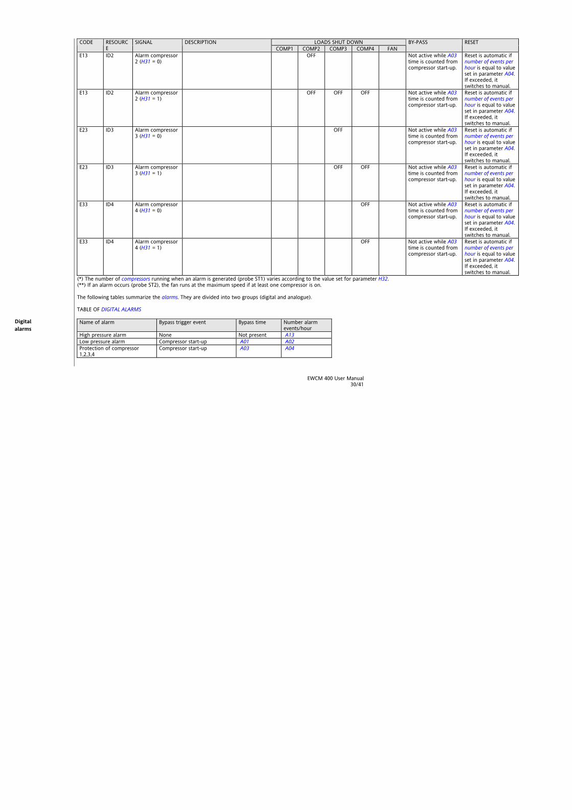
(*) The number of compressors running when an alarm is generated (probe ST1) varies according to the value set for parameter H32. (**) If an alarm occurs (probe ST2), the fan runs at the maximum speed if at least one compressor is on. The following tables summarize the alarms. They are divided into two groups (digital and analogue). TABLE OF DIGITAL ALARMS Name of alarm Bypass trigger event Bypass time Number alarm
events/hour High pressure alarm None Not present A13 Low pressure alarm Compressor start-up A01 A02 Protection of compressor 1,2,3,4
Compressor start-up A03 A04
Digital alarms

EWCM 400 User Manual 31/41
TABLE OF ANALOGUE ALARMS Name of alarm Event Bypass
time Trigger SET POINT
Hysteresis
Number alarm events/hour
Control probe
High condensation pressure alarm
None Not present
A06 A07 negative
A12
ST2
Low condensation pressure alarm
Compressor start-up
Par A08 A09 A10 positive
A11 ST2
Analogue alarms
EWCM 400 User Manual 32/41
10 TECHNICAL DATA
10.1 Technical data
Typical Min. Max. Supply voltage 12V~ 10V~ 14V~ Supply frequency 50Hz/60Hz --- --- Power 5VA --- --- Class of insulation 1 --- --- Operating ambient temperature 25°C -5°C 60°C Operating ambient humidity (non condensing) 30% 10% 90%
Ambient storage temperature 25°C -20°C 85°C Ambient storage humidity (non condensing) 30% 10% 90%
10.2 Electromechanical data
Digital outputs 120/240 V • Up to 5 2A ¼ hp 240V~; 1/8 hp 120V~ • 1 TRIAC 2A (only for EWCM 412)
Analogue output 0�10 V/ 4�20mA
• For the direct management of an inverter module (only for EWCM 418)
Outputs 24 V~ • 1 TRIAC output, non optic insulation, 500 mA max. Analogue inputs • 1 4...20 mA transducer
• 1 configurable input: 4...20 mA transducer or temperature sensor, range -30°C ÷ 90°C
Digital inputs • 7 voltage free digital inputs Terminals and connectors • 1 9-way snap-on high voltage connector AWG 16-28
• 1 16-way snap-on high voltage connector, pitch 4.2, AWG 16-28 • 1 5-way p2,5 5 connector with remote control and copy card, AWG 24-
30 • 1 3-way p2,5 connector for the direct management of an inverter
module (only for EWCM 418) Display and LEDs • 3 digits + sign
• 5 red LEDs Keys • 2 keys Serial terminals • 1 serial TTL terminal
The unit must be powered by means of an adequate transformer with the following characteristics: • Primary voltage: 230V~±10%; 110V~±10% • Secondary voltage: 12V~ • Supply frequency: 50Hz; 60Hz • Power: 5VA;
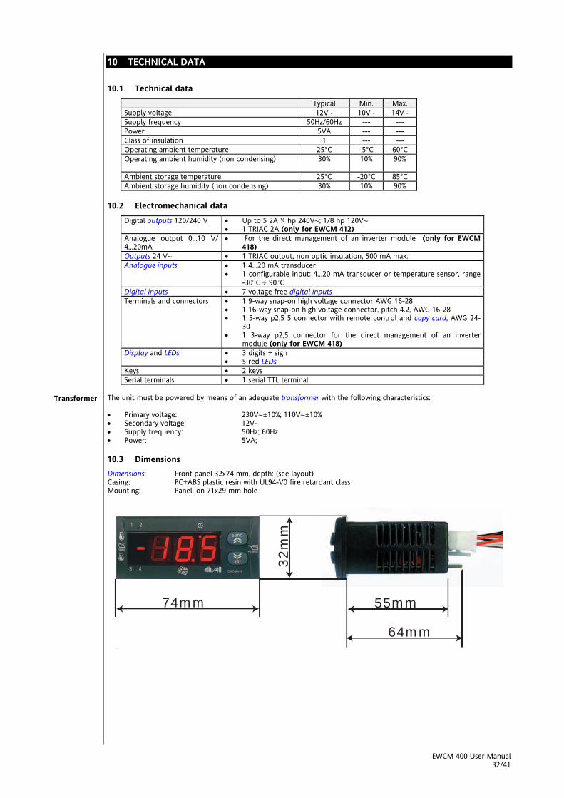
10.3 Dimensions Dimensions: Front panel 32x74 mm, depth: (see layout) Casing: PC+ABS plastic resin with UL94-V0 fire retardant class Mounting: Panel, on 71x29 mm hole
Transformer
74mm
32
mm
55mm
64mm
<IMG INFO> 425,1 181,5 0 2 0 9 -1 411 174

EWCM 400 User Manual 33/41
10.4 Standards The unit complies with the following European Union Directives: • EU Directive 73/23/EEC and subsequent amendments • EU Directive 89/336/EEC and subsequent amendments And is compliant with the following harmonized standards • LOW VOLTAGE: EN60730-2-6 and EN60730-2-9
10.5 Approvals UL E206120
UL approvals
EWCM 400 User Manual 34/41
11 USE OF DEVICE
11.1 Recommended use This unit is designed to control chillers and heat pumps with 1 circuit. For safety purposes, it is important to make sure that the control device is installed and used in accordance with the instructions supplied and that no parts subject to dangerous voltage are accessible to users during ordinary operation. The unit must be resistant to water and dust, depending on the application, and be accessible only by means of tools. This unit is suitable to be fitted on domestic appliances and/or equivalent units employed for air conditioning. In accordance with reference standard, this unit is classified as: • Electronic automatic control suited to be installed in standalone configuration or to be mounted on other units, in
relation to its manufacturing characteristics. • As a Type 1 control unit, in relation to its operating characteristics, manufacturing tolerances and derivatives. • As Class 2 device, in relation to its resistance to electric shocks • As Class A device, in relation to its class and the structure of its software
11.2 Forbidden use The use of the unit for applications other than those described is forbidden. It is worth remembering that the supplied relay contacts are functional and may be subject to failures (as the electronics controlling them may short circuit these relays or leave them open). For this reason, it is advisable to install the protection devices recommended in product specifications or other equivalent devices on the outside of the unit.
EWCM 400 User Manual 35/41
12 RESPONSIBILITIES AND RESIDUAL RISKS Eliwell shall not be liable for any damages deriving from:
• installation/use other than that prescribed and, in particular, that which does not comply with safety standards anticipated by regulations and/or those given herein;
• use on boards which do not guarantee adequate protection against electric shock, water or dust under the conditions of assembly applied;
• use on boards which allow access to dangerous parts without the use of tools; • tampering with and/or alteration of the products; • installation/use on boards not complying with the standards and provisions of current legislation.
EWCM 400 User Manual 36/41
13 DISCLAIMER This document is exclusive property of Eliwell Controls srl. and cannot be reproduced and circulated unless expressly authorized by Eliwell Controls srl Although all possible measures have been taken by Eliwell Controls srl l. to guarantee the accuracy of this document, it does not accept any responsibility arising out of its use.
14 APPENDIX
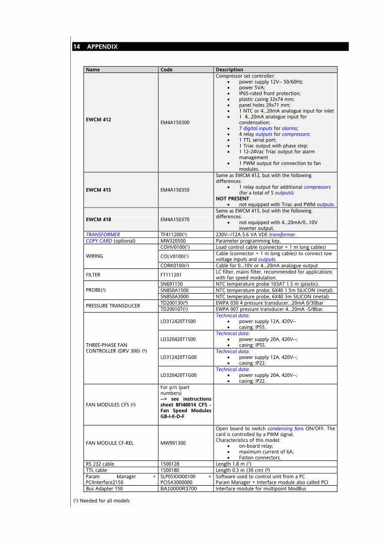
Name Code Description
EWCM 412 EM4A150300
Compressor set controller: • power supply 12V~ 50/60Hz; • power 5VA; • IP65-rated front protection; • plastic casing 32x74 mm; • panel holes 29x71 mm; • 1 NTC or 4�20mA analogue input for inlet • 1 4�20mA analogue input for
condensation; • 7 digital inputs for alarms; • 4 relay outputs for compressors; • 1 TTL serial port; • 1 Triac output with phase step; • 1 12-24Vac Triac output for alarm
management • 1 PWM output for connection to fan
modules.
EWCM 415 EM4A150350
Same as EWCM 412, but with the following differences:
• 1 relay output for additional compressors (for a total of 5 outputs)
NOT PRESENT • not equipped with Triac and PWM outputs.
EWCM 418 EM4A150370
Same as EWCM 415, but with the following differences:
• not equipped with 4�20mA/0...10V inverter output.
TRANSFORMER TF411200(1) 230V~/12A 5.6 VA VDE transformer. COPY CARD (optional) MW320500 Parameter programming key.
COHV0100(1) Load control cable (connector + 1 m long cables)
COLV0100(1) Cable (connector + 1 m long cables) to connect low voltage inputs and outputs. WIRING
CORK0100(2) Cable for 0...10V or 4...20mA analogue output
FILTER FT111201 LC filter, mains filter, recommended for applications with fan speed modulation.
SN691150 NTC temperature probe 103AT 1.5 m (plastic). SN8S0A1500 NTC temperature probe, 6X40 1.5m SILICON (metal). PROBE(3) SN8S0A3000 NTC temperature probe, 6X40 3m SILICON (metal). TD200130(4) EWPA 030 4 pressure transducer...20mA 0/30bar PRESSURE TRANSDUCER TD200107(5) EWPA 007 pressure transducer 4...20mA -5/8bar.
LD312420T1S00 Technical data:
• power supply 12A, 420V~ • casing: IP55.
LD320420T1S00 Technical data:
• power supply 20A, 420V~; • casing: IP55.
LD312420T1G00 Technical data:
• power supply 12A, 420V~; • casing: IP22.
THREE-PHASE FAN CONTROLLER (DRV 300) (6)
LD320420T1G00 Technical data:
• power supply 20A, 420V~; • casing: IP22.
FAN MODULES CFS (6)
For p/n (part numbers) --> see instructions sheet 8FI40014 CFS - Fan Speed Modules GB-I-E-D-F
FAN MODULE CF-REL MW991300
Open board to switch condensing fans ON/OFF. The card is controlled by a PWM signal. Characteristics of this model:
• on-board relay; • maximum current of 6A; • Faston connectors.
RS 232 cable 1500128 Length 1.8 m (7) TTL cable 1500180 Length 0.3 m (30 cm) (8) Param Manager + PCIInterface2150
SLP05XX000100 + PCI5A3000000
Software used to control unit from a PC Param Manager + Interface module also called PCI
Bus Adapter 150 BA10000R3700 Interface module for multipoint ModBus (1) Needed for all models
EWCM 400 User Manual 38/41
(2) Needed for model EWCM 418 (3) Used as alternative to pressure transducer: for inlet inputs (4) Needed for condensation input (5) Recommended for condensation input as an alternative to temperature probe (6) As alternative to other fan control modules (7) Other lengths available. We recommend using a 1.8 m long cable. The maximum length varies according to data transmission speed. (8) Other lengths available. We recommend using a 0.3 m long cable. Longer lengths may be used depending on electromagnetic disturbance in the environment. GENERAL NOTES:
• COHV and COLV cables are not required if they are supplied directly by the manufacturer. • Eliwell also offers several types of NTC probes that vary according to the type or length of cable (PVC or
silicone) installed. NOTE: EWCM 400 must be used with a transformer, cabling and relative probes.
14.1 CFS modules CFS series units are optional modules that when connected to main control modules allow the speed of single-phase fans to be adjusted with currents ranging from 2 A to 9 A. They have an �open board� format and several different models are available. --> see instructions sheet 8FI40014 CFS - Fan Speed Modules GB-I-E-D-F
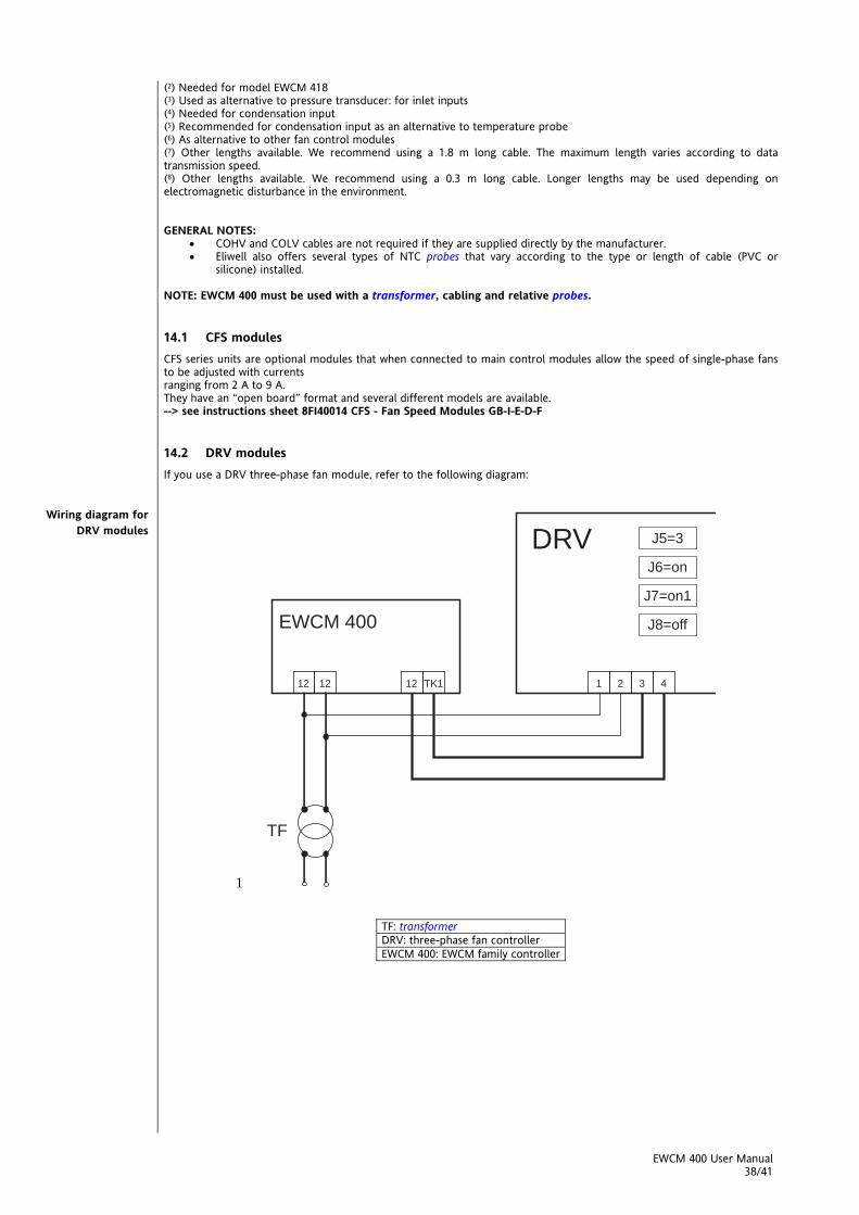
14.2 DRV modules If you use a DRV three-phase fan module, refer to the following diagram:
TF: transformer DRV: three-phase fan controller EWCM 400: EWCM family controller
Wiring diagram for DRV modules
1
EWCM 400
12 TK112 12
DRV
1 2 3 4
J5=3
J6=on
J7=on1
J8=off
TF
2 <IMG INFO>
EWCM 400 User Manual 39/41
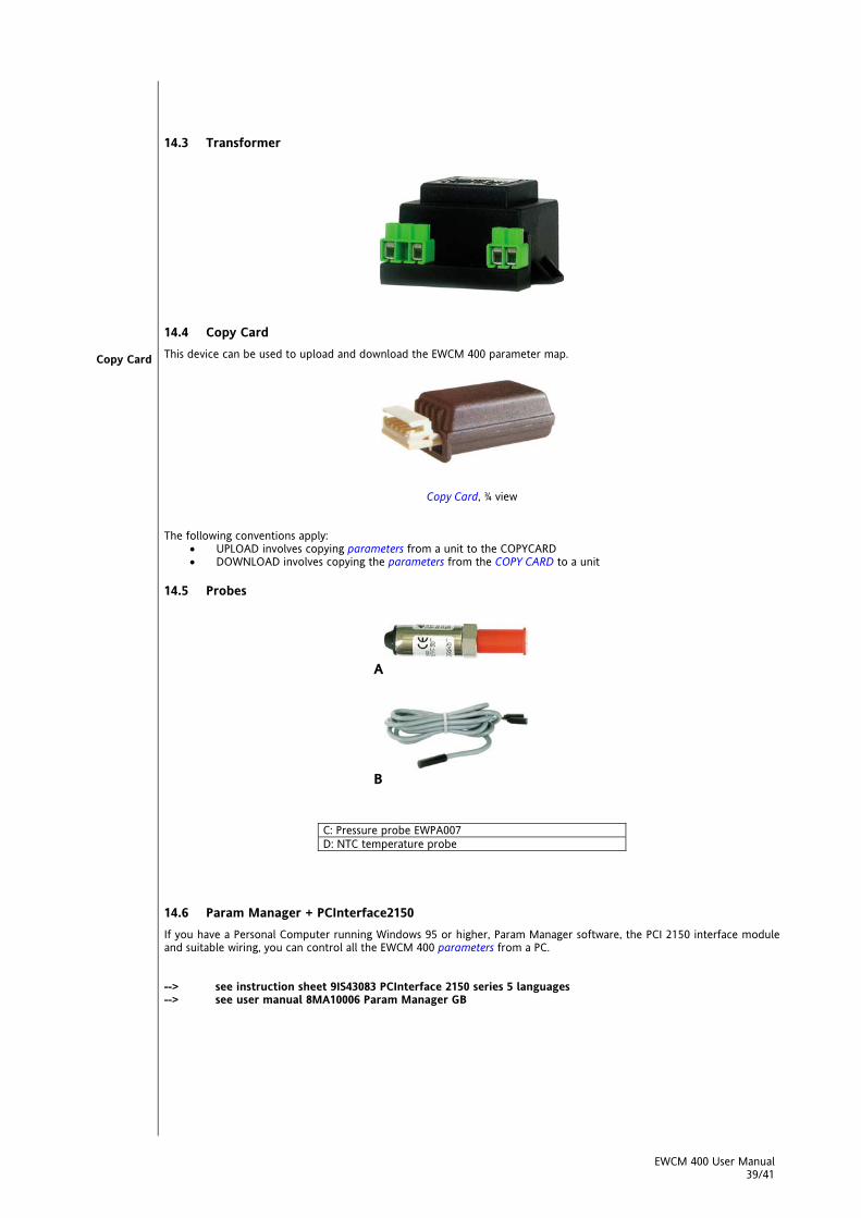
14.3 Transformer
14.4 Copy Card This device can be used to upload and download the EWCM 400 parameter map.
Copy Card, ¾ view
The following conventions apply:
• UPLOAD involves copying parameters from a unit to the COPYCARD • DOWNLOAD involves copying the parameters from the COPY CARD to a unit
14.5 Probes
A
B
C: Pressure probe EWPA007 D: NTC temperature probe
14.6 Param Manager + PCInterface2150 If you have a Personal Computer running Windows 95 or higher, Param Manager software, the PCI 2150 interface module and suitable wiring, you can control all the EWCM 400 parameters from a PC. --> see instruction sheet 9IS43083 PCInterface 2150 series 5 languages --> see user manual 8MA10006 Param Manager GB
Copy Card

15 ANALITIC INDEX
A Alarm (ALL) parameter table ......................................26 Alarm output .................................................................. 16 Alarm parameters..........................................................24 Alarm Set/Reset ..............................................................11 Alarms ..............................................................................27 Analogue alarms .........................................................30 Analogue inputs ................................................................7 APPENDIX ........................................................................ 36 Approvals ......................................................................... 32 B Balancing of operating hours .....................................15 Band ..................................................................................11 Band/Set combination..................................................11 Buttons ............................................................................. 11 C Callouts ..............................................................................3 CFS modules .................................................................... 37 Compressor (CP) parameter table .............................26 Compressor configuration ...........................................15 Compressor parameters ...............................................24 Compressor start/stop sequence ................................15 Compressor timing ........................................................15 Compressors .................................................................... 15 Condensing fan............................................................... 16 Condensing fan analogue output ---> 418 models
only ..................................................................................8 Condensing fan control ................................................ 20 Condensing fan Triac (TK) ---> 412 models only ......8 Configuration (CNF) parameter table ......................25 Configuration of analogue inputs.................................7 Configuration of condensing fan ...............................16 Configuration of digital inputs ......................................7 Configuration of outputs.................................................7 Configuration parameters ...........................................23 Configuration table for analogue inputs ....................7 Connecting the Copy Card..............................................9 Control of compressors � cooling/direct controller18 Copy Card ................................................................... 9; 38 Copying the parameter map ..........................................9 Cross references .................................................................3 D Decimal point value .........................................................7 Description of digital inputs ...........................................7 Description of parameters ........................................... 23 Device status ................................................................... 12 DIAGNOSTICS ................................................................. 27 Digital alarms .................................................................29 Digital inputs ...................................................................7 Dimensions ...................................................................... 31 DISCLAIMER..................................................................... 35
Display ..............................................................................11 Downloading the parameter map................................9 DRV modules ...................................................................37 DRV modules:Wiring diagram for DRV modules ....37 E Electromechanical data ................................................31 EWCM 415 wiring diagram with temperature and
current input .................................................................6 EWCM 418 wiring diagram with temperature and
current input .................................................................6 F Fan (FAN) parameter table..........................................26 Fan module control (TK1) ---> 412 models only ......8 Fan parameters...............................................................25 Fixed sequence ................................................................15 for EWCM 412 with temperature and current
input ...............................................................................5 Forbidden use ..................................................................33 FUNCTIONS .....................................................................22 H Heating/inverse controller............................................18 Highlights ...........................................................................3 I Impulse duration ............................................................16 INSTALLATION .................................................................. 5 INTRODUCTION................................................................ 4 K Keyboard ..........................................................................11 L LEDs ...................................................................................11 List of alarms ...................................................................27 M Menu structure................................................................13 Modifying status of On-Off device..............................12 N Number of events per hour ..........................................27 Number of power steps .................................................15 O OFF-ON and ON-ON sequence compressor 1 .........15 On/off timing...................................................................15 On/on timing...................................................................15 ON-OFF output ...............................................................16 ON-OFF sequence...........................................................21 ON-ON and OFF-OFF compressor timing.................15 ON-ON and OFF-OFF sequence compressor 2 ........16 Operating modes ............................................................18 Outputs ...............................................................................7 P Param Manager + PCInterface2150 ..........................38 PARAMETERS...................................................................23 Phase shift ........................................................................16 Physical quantities and units of measurement........10

EWCM 400 User Manual 41/41
Pick-up..............................................................................16 Polarity of digital inputs..................................................7 Polarity of relays................................................................8 Polarity RL1-RL4 .............................................................15 Probes ............................................................................... 38 Programming parameters and displaying unit
status: menu levels .................................................... 12 Proportional or ...............................................................16 R Recommended use......................................................... 33 Registration of working hours..................................... 22 Relays (RL) ........................................................................8 RESPONSIBILITIES AND RESIDUAL RISKS ... 34 S Safety timing ...................................................................15 Selection of operating mode .......................................18 Serial output ......................................................................9 Silent speed......................................................................20 Standards......................................................................... 32
Stand-by ...........................................................................18 SYSTEM CONFIGURATION ...........................................15 T Table of parameters.......................................................25 Technical data ................................................................31 TECHNICAL DATA...........................................................31 TEMPERATURE CONTROL FUNCTIONS.....................18 Transformer ..............................................................31; 38 U UL approvals....................................................................32 Units of measurement ...................................................10 USE OF DEVICE ................................................................33 USE OF MANUAL .............................................................. 3 USER INTERFACE.............................................................11 V Ventilation chart ............................................................20 W Wiring diagram.................................................................5 Wiring diagrams for EWCM 400 devices ..................... 5
EWCM 400 User Manual 2006/3/
Cod: 9MA10003