ex-0012-000002-pce - washington savage/adjudication/exhibits/tesoro/exhibit... · • api rp 1110...
TRANSCRIPT

f) BergerABAM 210 East 13th Street, Suite 300, Vancouver, Washington 98660-3231 360/823-6100 • 360/823-6101 Fax • www.abam.com
26 February 2015
Mr. Stephen Posner Energy Facility Site Evaluation Council Washington Utilities and Transportation Commission P.O. Box 43172 Olympia, WA 98504-3172
Subject: Vancouver Energy EFSEC Application No. 2013-01, Docket No. EF131590 Response to EFSEC Draft EIS Data Request 3
Dear Mr. Posner:
On behalf of Tesoro Savage Petroleum Terminal LLC (the Applicant), BergerABAM is providing a response to the Energy Facility Site Evaluation Council's (EFSEC) Draft EIS Data Request 3, dated 03 February 2015.
Please feel free to contact me at 206/431-2373, or [email protected], if you have any questions about this submittal. We look forward to further coordination with you, your staff, and EFSEC' s consultants.
Sincerely,
~.~ Irina Makarow Senior Environmental Project Manager
IM:keh cc:
Kelly Flint, Savage Companies Jay Derr, Van Ness Feldman
EX-0012-000001-PCE

EX-0012-000002-PCE

Response to EFSEC Draft EIS Data Request 3
Code Data Request Item
Fire Safety
FS-1 Applicable codes. regulations. design guides. construction methods. etc.
Please list all safety-related code and regulatory requirements referenced and followed for this facility. Often such items are compiled and listed as a standalone document or within the facility Basis of Design document (see Paragraph 2.2). Some examples of typical code and standard listings we would expect to see are as follows:
• NFPA 307 Construction and Fire Protection of Marine Terminals. Piers and Wharfs
• API RP 500 C Classification of areas for electrical installation of petroleum and gas pipeline transportation systems
• API RP 2003 Protection against ignitions arising out of static. lightning and stray currents
• API STD 2610 Design, Construction . Operation. Maintenance & Inspection of Terminal and Tank Facilities
• OCIMF Oil companies International Marine Forum. applicable sections
• ISGOTI International Safety Guide for Oil Tankers and Terminals. applicable sections
• NEC National Electrical Code
• NFPA 30 Flammable and Combustible Liquids Code
• OSHA Occupational Safety and Health Administration
Vancouver Energy Response to DEIS Data Request 3
Applicant Response
Please see the Fire System Operation Description report. Attachment 1 to this letter_ Applicable design criteria are listed in Chapter 3 of the Report.
The Applicant has also provided applicable regulatory requirements as part of the Application for Site Certification. Section 2 .23 - see Attachment 2 to this letter_
26 Februaiy 2015 Page 1 of4
EX-0012-000003-PCE

Response to EFSEC Draft EIS Data Request 3
!Code I Data Request Item
Fire Safety
• AWWA American Water Works Association
• API 650 Welded Tanks for Oil Storage
• API RP 1110 Pressure Testing of Liquid Petroleum Pipelines
• API RP 2003 Protection against ignitions arising out of static. lightning and stray currents
• API Spec 5L Line Pipe
• API Spec 6D Pipeline Valves (Gate . Plug, Ball. and Check Valves)
• API STD 6.3 Manual of Petroleum Measurement Standards
• API STD 1104 Welding of Pipelines and Related Facilities
• ASME/ ANSI Applicable standards and sections for pipe, fittings, valves
• ASME/ ANSI B31.4 Liquid Transportation Systems for Hydrocarbons. Liquid Petroleum Gas. Anhydrous Ammonia. and Alcohols
• ASME BPVC Boiler and Pressure Vessel Code. applicable sections
• ASNT American Society for Non-Destructive Testing, applicable standards
• 40 CFR 40 112. 7 Spill Prevention . Control and Countermeasure Plans
FS-2 Basis Of Design
Provide the reviewers with the current Basis of Design document for this facility. This should include descriptions of the general facility design; specific primary system design; secondary and utility systems; wind and seismic design criteria; fire prevention. detection and
Vancouver Energy Response to DEIS Data Request 3
I Applicant Response
Please see Attachment 1 to this letter.
26 Februaiy 2015 Page 2 of4
EX-0012-000004-PCE

Response to EFSEC Draft EIS Data Request 3
!Code I Data Request Item
Fire Safety
suppression systems; piping, mechanical and electrical systems; environmental issues and guidelines; security measures; and design codes and criteria (as discussed in Paragraph 2.1)_ It is recognized that Basis of Design documents may not exist in a single. cohesive format. but may instead consist of multiple documents. organized and formatted differently_
FS-3 Specific Items Listing
In addition to the general documentation listed in the Basis of Design request. the following is a specific listing of requested items_ Again. if these documents are not available at this time. please note when they will be available for review_
• Facility process flow diagrams (oil . utility and fire protection)
• Facility piping and instrumentation diagrams (Oil . utility and fire protection)
• Electrical safety systems
• Emergency shutdown systems
• Spill containment systems . descriptions and volume calculations
• Spill response system descriptions
• Hazardous area classification plans and details
• Piping and equipment plans
• Fire Protection system design (prevention. detection. response. suppression . outside aid)
• Ship-to-shore connection systems . methods. safety procedures
Vancouver Energy Response to DEIS Data Request 3
I Applicant Response
Please see Attachment 1 to this Jetter for information regarding fire safety systems_
Spill prevention. control and response systems have been described in the PDEIS at Section 2 _2_ 7 and 4 _18_ see also response to Item PD-1 (DEIS Data Request 1) in reference to spill prevention control and countermeasures and oil spill contingency plans_
In addition to the information above. the Applicant has committed to preparing a series of pre-construction and pre-operations plans as indicated in Attachment 3 (originally provided to EFSEC on 26 January 2015)_ Several of the plans to be submitted in April 2015 will address safety measures. training, and facility operating procedures_
26 Februaiy 2015 Page 3 of 4
EX-0012-000005-PCE
Response to EFSEC Draft EIS Data Request 3
!Code I Data Request Item
Fire Safety
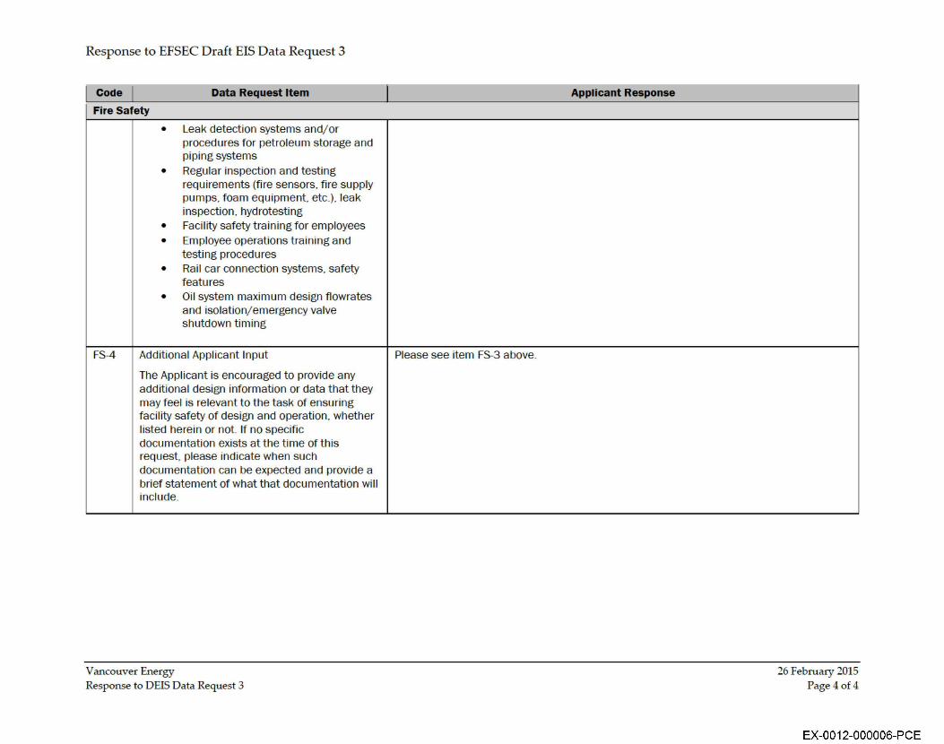
• Leak detection systems and/or procedures for petroleum storage and piping systems
• Regular inspection and testing requirements (fire sensors. fire supply pumps, foam equipment. etc.). leak inspection. hydrotesting
• Facility safety training for employees
• Employee operations training and testing procedures
• Rail car connection systems. safety features
• Oil system maximum design flowrates and isolation/ emergency valve shutdown timing
FS-4 Additional Applicant Input
The Applicant is encouraged to provide any additional design information or data that they may feel is relevant to the task of ensuring facility safety of design and operation. whether listed herein or not If no specific documentation exists at the time of this request. please indicate when such documentation can be expected and provide a brief statement of what that documentation wi ll include.
Vancouver Energy Response to DEIS Data Request 3
I Applicant Response
Please see item FS-3 above.
26 Februaiy 2015 Page 4of4
EX-0012-000006-PCE

Response to EFSEC Draft EIS Data Request 3
Attachment 1
Vancouver Energy 26 February 2015 Response to DEIS Data Request 3
EX-0012-000007-PCE

Fire System Operation Description
Vancouver Energy Vancouver, Washington
Submitted: February 26, 2014 FINAL
Poole Fire Protection
innovative leader trusted partner
19910 West 161 st Street Olathe, Kansas 66062
www.poolefire.com
EX-0012-000008-PCE

Table of Contents Chapter 1 - Introduction ........................ ········································································ ... 1 Chapter 2 - Facility & Area Overview .............................................................................. 1
2.1 Facility Overview ............................................................................................... 1 2.2 Area 200 - Unloading and Office ...................................................................... 1 2.3 Area 300 - Storage ........................................................................................... 2 2.4 Area 400 - Marine Terminal. ....... ...................................................................... 2 2.5 Area 500 - Transfer Pipelines ........................................................................... 3 2.6 Area 600- West Boiler ..................................................................................... 3
Chapter 3 - Applicable Design Criteria .... ........................................................................ 3 Chapter 4 - Site Water Supply ......................................................................................... 4
4.1 Water Supply Overview .................................................................................... 4 4.2 Adequacy .......................................................................................................... 5 4.3 Arrangement of Fire Hydrants and Water Supply ............................................. 5 4.3.1 Area 200 - Unloading and Office ..................... .......................................... 5 4.3.2 Area 300 - Storage .................................................................................... 6 4.3.3 Area 400 - Marine Terminal ...................................................................... 7
4.4 Cross-Connection Control ............... .................................................................. 7 Chapter 5 - Fire Pumps ................................................................................................... 7
5.1 General Overview ............................................................................................. 7 Chapter 6 - Fire Suppression Systems ............................................................................ 8
6.1 Sprinkler Systems, Monitors, and Foam Suppression Systems ........................ 8 6.1.1 Use of Foam Fire Suppression Agents .................................. .................... 8 6.1.2 Area 200 - Unloading and Office ............................................................... 9 6. 1 . 3 Area 300 - Storage Area ......................................................................... 1 0 6.1 .4 Area 400 - Marine Terminal Area .... ........................................................ 11
Chapter 7 - Fire Alarm System ...................................................................................... 12 7.1 Fire Alarm System Overview ........................................................................... 12 7.2 Fire Alarm Panel Reporting Capability .... ........................................................ 12 7.3 Initiating Devices ............................................................................................. 12 7.3.1 Linear Heat Detection .............................................................................. 12 7.3.2 Foam System Manual Release Stations .................................................. 13 7.3.3 Waterflow Switches ................................................................................. 14
7.3.4 Manual Pull Stations···· ············································································ 14 7.3.5 Smoke Detectors ..................................................................................... 14 7.3.6 Gas Detection .......................................................................................... 14 7.3.7 Valve Tamper Switches ......................... .................................................. 15
7.4 Fire Alarm Notification Appliances .................................................................. 15 Chapter 8 - Conclusion .................................................................................................. 15
Fire System Operation Description Poole Fire Protection
EX-0012-000009-PCE

Chapter 1 - Introduction
This document has been developed at the request of Tesoro Savage Petroleum Terminal LLC (the Applicant) to provide a high level overview of the Fire Protection (FP) and Fire Alarm (FA) systems and equipment proposed for Vancouver Energy (Facility). This document describes: the conditions which activate or trip the respective fire safety systems; what alarms or signals are transmitted; the anticipated result of the system; and site water supply.
Chapter 2 - Facility & Area Overview
2. 1 Facility Overview The Facility is located at the Port of Vancouver in the City of Vancouver, Washington. This Facility will unload crude oil from railcars, pump the crude oil to storage tanks and then pump the crude oil from the storage tanks to the transport vessels at the Marine Terminal Area. The Facility has been broken down into five separate and distinct areas: 1) Area 200 - Unloading and Office; 2) Area 300 - Storage; 3) Area 400 - Marine Terminal; 4) Area 500 - Transfer Pipelines; and 5) Area 600 - West Boiler. Below is a brief description of each area.
2.2 Area 200 - Unloading and Office The rail unloading facilities will include three tracks and associated equipment for unloading of crude oil. The unloading tracks will be located inside a structure. Each unloading track will accommodate 30 cars for a total length of approximately 1,800 feet. The structure will be approximately 1,850 feet long and 90 feet wide to accommodate the length of these unloading tracks and the unloading operations.
The structure has a complete metal roof, while the walls will only consist of seven metal wall panels spaced along the south side of the structure. These seven metal wall panels will be spaced at locations corresponding with E-houses, the fire pump/foam skid building, and other appurtenances that are to be located on the south side of the structure. The remainder of the wall area on the structure will be open. Within the structure there will be two elevated walkways running the length of the structure used in the unloading process, and five crossover egress walkways providing access to the north and south sides of the structure spaced approximately every 357 feet. There will be three rail tracks running east to west, two trenches (approximately 7- 9 foot wide by 5 foot deep) accommodating the piping system that is used to transport the crude oil to the pump basins (located between the tracks), and 10 pump basins (5 per trench), which will be spaced approximately every 355 feet that house the transfer pumps. These transfer pumps will be used to pump the crude oil from Area 200 to the storage tanks in Area 300. The structure will be completely protected by a fire detection and sprinkler system.
Fire System Operation Description Page 1 of 15 Poole Fire Protection
EX-0012-000010-PCE

Access stairs will be provided between the railcars which will enable workers performing any unloading operations at the track level to exit up the stairs to the elevated crossovers and over the railcars to reach an exterior exit from the structure.
Other structures located in the Area 200 include control room/E-houses and the fire pump/foam skid building.
The Facility will require three approximately 3,400-square-foot office buildings to house administrative functions, lockers, restrooms, and other employee support facilities. These buildings will be located approximately 225 feet to the North of the rail unloading structure. These buildings consist of modular office trailers that are pre-built off site and placed at their specific location on the job site. The Office Building and change rooms will not be provided with an automatic suppression system.
2.3 Area 300 - Storage Six above ground storage tanks will be constructed in Area 300. The storage tanks will have a nominal storage capacity of 380,000 barrels (15,960,000 gallons) each and they will be approximately 50 feet tall with a diameter of 240 feet. All tanks will be located inside a perimeter dike capable to contain 110% of the volume of the largest tank plus the anticipated precipitation from a 24 hour, 100 year storm. The tanks will be positioned so that the distance between each tank is 120 feet in any direction. The distance from the tank to the dike varies from a minimum distance of approximately 33 feet to a maximum of 150 feet.
Other structures located in the Area 300 will include a Pump Basin for the pumps that will be used to transfer the crude from the tank storage area to the vessels at Berth 13. A Storage Building, a control room/E-house, and a Fire Pump and Foam Building will also be located in Area 300.
2.4 Area 400 - Marine Terminal The Marine Terminal Area will consist of berths 13 and 14. Crude oil will be pumped from the Storage Area in a 36-inch pipe to Berth 13. The berth will be able to accommodate vessels with varying capacities, with loading rates of up to 32,000 barrels per hour. Safety measures include automatic shutoff valves, a return and stripping line for the crude to return back to the storage tanks, a marine vapor combustion unit, floating booms and manual fire protection features.
Berth 14 will be used for storage of and access to a skiff that will be used to deploy a fence boom in the water around the ship. There are no crude loading operations planned for Berth 14. Safety measures include manual fire protection features.
Other structures located at the Marine Terminal Area will include a control room/Ehouse, vapor blower staging unit, Fire Pump and Foam Building, and a dock safety unit.
Fire System Operation Description Page 2 of 15 Poole Fire Protection
EX-0012-000011-PCE
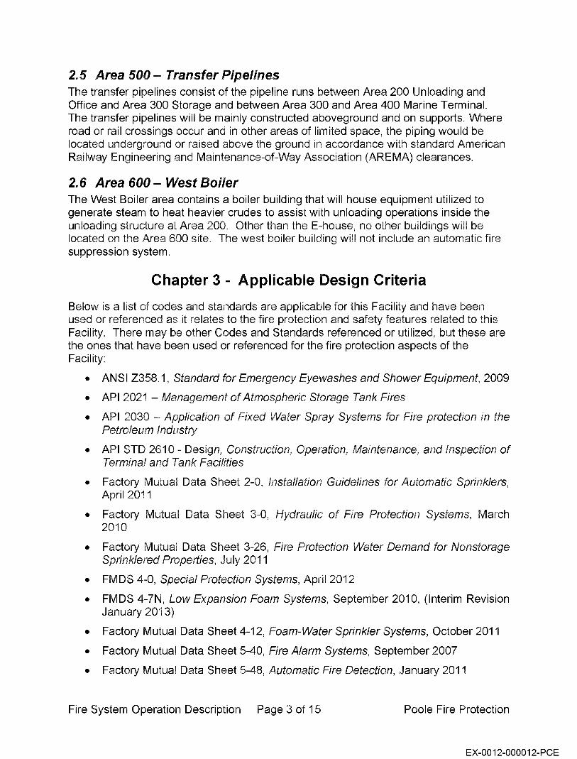
2.5 Area 500 - Transfer Pipelines The transfer pipelines consist of the pipeline runs between Area 200 Unloading and Office and Area 300 Storage and between Area 300 and Area 400 Marine Terminal. The transfer pipelines will be mainly constructed aboveground and on supports. Where road or rail crossings occur and in other areas of limited space, the piping would be located underground or raised above the ground in accordance with standard American Railway Engineering and Maintenance-of-Way Association (AREMA) clearances.
2. 6 Area 600 - West Boiler The West Boiler area contains a boiler building that will house equipment utilized to generate steam to heat heavier crudes to assist with unloading operations inside the unloading structure at Area 200. Other than the E-house, no other buildings will be located on the Area 600 site. The west boiler building will not include an automatic fire suppression system.
Chapter 3 - Applicable Design Criteria
Below is a list of codes and standards are applicable for this Facility and have been used or referenced as it relates to the fire protection and safety features related to this Facility. There may be other Codes and Standards referenced or utilized, but these are the ones that have been used or referenced for the fire protection aspects of the Facility:
• ANSI Z358.1, Standard for Emergency Eyewashes and Shower Equipment, 2009
• API 2021 - Management of Atmospheric Storage Tank Fires
• API 2030 - Application of Fixed Water Spray Systems for Fire protection in the Petroleum Industry
• API STD 2610 - Design, Construction, Operation, Maintenance, and Inspection of Terminal and Tank Facilities
• Factory Mutual Data Sheet 2-0, Installation Guidelines for Automatic Sprinklers, April 2011
• Factory Mutual Data Sheet 3-0, Hydraulic of Fire Protection Systems, March 2010
• Factory Mutual Data Sheet 3-26, Fire Protection Water Demand for Nonstorage Sprinklered Properties, July 2011
• FMDS 4-0, Special Protection Systems, April 2012
• FMDS 4-7N, Low Expansion Foam Systems, September 2010, (Interim Revision January 2013)
• Factory Mutual Data Sheet 4-12, Foam-Water Sprinkler Systems, October 2011
• Factory Mutual Data Sheet 5-40, Fire Alarm Systems, September 2007
• Factory Mutual Data Sheet 5-48, Automatic Fire Detection, January 2011
Fire System Operation Description Page 3 of 15 Poole Fire Protection
EX-0012-000012-PCE

• Factory Mutual Data Sheet 7-32, Ignitable Liquid Operations, April 2012
• Factory Mutual Data Sheet 7-88, Flammable Liquid Storage Tanks, October 2011
• International Building Code, 2012
• International Fire Code, 2012
• International Safety Guide for Oil Tankers and Terminals (ISGOTT), Fifth Edition
• NFPA 10, Standard for Portable Fire Extinguishers, 2010
• NFPA 11, Standard for Low-, Medium-, and High-Expansion Foam, 2010
• NFPA 13, Standard for the Installation of Sprinkler Systems, 2010
• NFPA 15, Standard for Water Spray Fixed Systems for Fire Protection, 2012
• NFPA 16, Standard for the Installation of Foam-Water Sprinkler and Foam-Water Spray Systems, 2011
• NFPA 20, Standard for the Installation of Stationary Pumps for Fire Protection, 2010 Edition
• NFPA 24, Standard for the Installation of Private Fire Service Mains and Their Appurlenances, 2010
• NFPA 30, Flammable and Combustible Liquids Code, 2012 Edition
• NFPA 70, National Electrical Code, 2011
• NFPA 72, National Fire Alarm and Signaling Code, 2010
• NFPA 307, Standard for the Construction and Fire Protection of Marine Terminals, Piers, and Wharves, 2011 Edition
Chapter 4 - Site Water Supply
4. 1 Water Supply Overview Currently the site has existing water mains provided from both the City of Vancouver and the Port of Vancouver. Two tests were performed on May 30, 2013 on fire hydrants at Area 300 - Storage and Area 400 - Marine Terminal on the City of Vancouver water distribution system. They yielded the following flow test results:
Area 300 - Storage: Static Pressure= 84 psi Residual Pressure = 63 psi Flow= 2,005 gpm
Area 400 - Marine Terminal: Static Pressure = 81 psi Residual Pressure = 62 psi
Fire System Operation Description Page 4 of 15 Poole Fire Protection
EX-0012-000013-PCE

Flow = 2, 127 gpm
Based on the information provided by the City of Vancouver, below is the available water supply for the Area 200 rail unloading structure:
Static Pressure = 50 psi Residual Pressure = 20 psi Flow= 2,500 gpm
The City of Vancouver water distribution system will supply water to the fire hydrants on the South side of the rail unloading structure as well as the fire pump that feeds the suppression systems inside the Rail unloading structure.
Additionally, the City of Vancouver water distribution system will supply water to the fire pump, which in return will supply water to the suppression systems on the tanks, and the fire hydrants around the dike at the Storage Area.
The City of Vancouver water supply at the Marine Terminal Area will supply the fire pump that feeds the elevator monitor nozzles equipment to the dock.
4.2 Adequacy The current available water supply will be supplied from the on-site dedicated fire water gridded distribution system. It is been discussed and confirmed that the on-site system water supply available from the City of Vancouver to the Facility is more than adequate to meet the demand of the manual fire operations and the automatic fire suppression system. The City of Vancouver system is accessible at all Facility site locations and has been deemed reliable; therefore, the City of Vancouver water supply will be the water service used in the design of this Facility, not the Port of Vancouver water supply.
4.3 Arrangement of Fire Hydrants and Water Supply
4.3.1 Area 200 - Unloading and Office Fire hydrants will be provided on the south side of the Rail unloading structure spaced at every 300 feet accessible fire department apparatus. The fire hydrants will be supplied by the City of Vancouver water distribution system.
The hydrants will be located on the south side of the track that is located south of the Rail unloading structure. Procedures will be in place for cooperation with those companies using the tracks to the south of the unloading building to allow access to the unloading building from the hydrants
The fire pump supplying water to the automatic fire suppression systems in the Rail unloading structure is supplied from the City of Vancouver water distribution system. The fire pump is located in the Fire Pump/Foam Building immediately adjacent to the Rail unloading structure.
Fire System Operation Description Page 5 of 15 Poole Fire Protection
EX-0012-000014-PCE

4.3.2 Area 300 - Storage Fire hydrants will be provided for fire department use around the perimeter of Area 300 -Storage accessible by fire department apparatus. The fire hydrants will be located on the dike spaced every 300 feet, with two fire hydrants located inside the dike area near the intersection of the intermediate dikes. These fire hydrants will be supplied from the fire pump for the storage area and will include a monitor nozzle that can be used to cool the tanks, reduce fire exposure and also be used to apply the self-healing biodegradable foam.
Each hydrant will be equipped with a monitor nozzle and foam eductor and pick-up line that can be placed in a bucket, pail or other portable device of foam concentrate, which through a venture effect, will draw foam concentrate from the pail/container to generate a foam solution (see figure below).
The flow of water from these monitor nozzles are provided to create a cooling effect on the tank wall. The foam eductor provided on each monitor nozzles will allow the hydrant to spray a foam water solution and control a small pool fire within the dike area. A predetermined size of foam concentrate stored in bucket, pail or other portable device will be kept in the Fire Pump I Foam Building. When the need arises for its use, such as a small spill or rubbish fire, the foam concentrate will be taken to the appropriate fire hydrant and the hose placed in the bucket, pail or other portable device. The nozzle will draw the foam in at the manufacturer determined proportioning rate to achieve the desired concentration of foam/water solution.
Additionally, an elevated monitor nozzle supplied with foam-water from the Fire Pump I Foam Building will be located near the crude oil pump basin with the primary purpose of providing manual fire suppression to the pump basin. This monitor nozzle for the crude oil pump basin will be capable of providing a 3% foam application to the pump basin area. Utilizing a flow rate of 750 gpm will provide coverage of the crude oil pump basin.
Fire System Operation Description Page 6 of 15 Poole Fire Protection
EX-0012-000015-PCE

FHE H'OHANT C?E:'(~.11NG H~N[JLE ......... ~·~·-·"
! 1 /?'' FPE HYP"~4'··T G~TE \i.O.L\'E
_,.../ __ .... /
~ ~· ·· -· 2 '/2" FIRE f·Nif•;eNT CATE '#.lvE
~ r
The City of Vancouver water distribution system will supply water to the fire pump being provided to supply water to the automatic fire suppression systems for the storage tanks and to the fire hydrant/monitor system around the perimeter of the storage area. The fire pump is located in the Fire Pump/Foam Building immediately west of the storage tanks along the edge of the dike.
4.3.3 Area 400 - Marine Terminal A fire hydrant will be provided for fire department use near Area 400 - Marine Terminal. The on-site City of Vancouver water distribution system will supply water to the fire hydrant and the fire pump for this area to support the fire protection systems at the Marine Terminal area. The fire pump will be located in the Fire Pump/Foam Building immediately adjacent to the Marine Terminal area.
4.4 Cross-Connection Control A backflow prevention assembly will be on the water supply for each of the above described areas upstream of the fire pump to protect the potable water distribution system. Due to the design including foam, reduced pressure backflow prevention assemblies will be utilized.
Chapter 5 - Fire Pumps
5. 1 General Overview Fire pumps will be required to supplement the city water supply at all locations; the rail unloading structure, the Area 300 - Storage, and Area 400 - Marine Terminal. The fire pumps will be diesel driven, as power is not considered to be reliable per the definition
Fire System Operation Description Page 7 of 15 Poole Fire Protection
EX-0012-000016-PCE

in NFPA 20, and there are no plans for the Facility to have backup power. The fire pumps will be located in a skid enclosure that will also contain the fire suppression system risers as well as fire alarm equipment. The Fire Pump I Foam Buildings will be completely sprinklered and separated from any other occupancies/structures as required by NFPA 20 to help ensure the reliability of the fire protection systems and fire pumps.
The fire pumps will be set up to automatically start upon a drop in pressure downstream of the fire pump system. The pressure drop will be monitored to a pressure switch in each fire pump controller. Once the pressure switch reaches the predetermine setting, a signal will be sent from the fire pump controller to the diesel engine to automatically start the engine/pump. The fire pump will boost the pressure and flow rate in the respective system to provide the required flow rate and pressure to the respective fire suppression system.
Upon the opening of a fire hydrant around Area 300 - Storage, or the tripping of one of the fire suppression systems (sprinkler or foam system) the pressure would reduce requiring the respective fire pump at the respective area to activate increasing the pressure in the fire protection system to provide adequate fire flow (pressure and flow rate) to meet the demand of the respective system.
The Area 300 - Storage Fire Pump and Foam Building will also include a jockey pump to maintain pressure of the underground piping around the dike. The jockey pump is only meant to maintain pressure to account for thermal expansion, minor leaking in the underground piping and small fluctuations in pressure, having a flow rate of 5 - 10 gpm.
Below are the sizes of the fire pumps to be provided for each respective area: • Area 200 Unloading and Office- 2000 gpm at 125 psi • Area 300 Storage- 2500 gpm at 125 psi • Area 400 Marine Terminal- 2000 gpm at 125 psi
Chapter 6 - Fire Suppression Systems
6. 1 Sprinkler Systems, Monitors, and Foam Suppression Systems
6.1.1 Use of Foam Fire Suppression Agents The best method of controlling a flammable or combustible liquid fire is through the use of foam fire extinguishing agents. The current plan is to use a self-healing biodegradable foam manufactured by Solberg which is an environmentally friendly product. Further discussion regarding environmental impact can be found in NFPA 11, Annex F.
The Harmonized Offshore Chemical Notification Format (HOCNF) applies to all chemicals used in connection with offshore exploration and production activities in the OSPAR maritime area. OSPAR is the mechanism by which fifteen Governments of the western coasts and catchments of Europe, together with the European Union,
Fire System Operation Description Page 8 of 15 Poole Fire Protection
EX-0012-000017-PCE

cooperate to protect the marine environment of the North-East Atlantic. This program includes any chemical that can be discharged into a river and ultimately find its way into the North Sea.
The raw materials used in the Solberg self-healing biodegradable foam have been evaluated to the HCNOF and is the only foam to date that has gone through this evaluation. This evaluation, which determines the impact of products discharged into marine and freshwater environments, concluded that the Solberg self-healing biodegradable foam is acceptable for use in the North Sea and in areas that discharge into the North Sea. As well, the German Institute of Hygiene has found the Solberg selfhealing biodegradable foam to be of low impact upon discharge to the environment. It should be noted that fluorinated foam products will not achieve those listings because of the persistence of the fluorine molecule. For example, Solberg self-healing biodegradable foam is permitted by the Norwegian Government to allow runoff directly into the Fiords of the North Sea. This is not permitted with fluorinated surfactant based foam products.
Foam application will be limited to the minimum amount needed to control and extinguish a flammable or combustible liquid fire and to avoid to the extent practicable releases of foam to surface water.
6.1.2 Area 200 - Unloading and Office A closed-head foam-water pre-action sprinkler system will be installed inside the rail unloading structure at the roof level, under walkways (as required by code) and in the pump basin areas. The structure will be divided in to five zones, each zone will be activated either manually from the foam manual release stations or automatically from the linear heat detection that will be installed at the roof level and at the pump basin level for that associated zone. The pump basins are located in the center of each zone respectively between the tracks. Note that this system is a closed-head pre-action foam-water system; therefore, foam-water solution will only be discharged once the fire is large enough to activate the linear heat detection, trip the valve and then activate the sprinklers above the fire. Foam will be used to control and extinguish the crude oil pool fire and will also provide cooling to the railcars and any adjacent equipment or building elements.
A closed-head wet-pipe sprinkler system (water only, no foam) will be provided for the Fire Pump I Foam Building in accordance with NFPA 20, Section 4.12.1.1.2. The wetpipe system contains water under pressure, therefore, when a fire starts and grows large enough to trip a sprinkler at the ceiling/room a sprinkler or sprinklers are expected to control the fire.
The closed-head foam-water pre-action sprinkler system and the closed-head wet-pipe sprinkler system will be pressurized by the City of Vancouver water distribution system and fire pump; therefore, when either system activates, and pressure drops on the downstream side of the fire pump, the fire pump will start and supplying adequate pressure to the system to control or extinguish the fire.
Fire System Operation Description Page 9 of 15 Poole Fire Protection
EX-0012-000018-PCE

6.1.3 Area 300 - Storage Area An automatic fixed foam system will be provided for each storage tank to protect the seal area of the internal floating roof. This system will be a Pre-Action Foam System activated by the linear heat detection system installed at the foam dam of the floating roof or by the manual foam release stations associated with each respective tank. See the figures below to reflect the typical configuration and installation of the foam maker on the tank. The linear heat detection cable located around the foam dam will be connected to the fire alarm system (see Chapter 7 for details on the fire alarm and linear detection system). The pre-action valve and foam concentrate tank will be located in the Fire Pump I Foam Building.
The internal floating roof tank will be protected by a Type II Discharge Outlet (i.e. foam chamber) which delivers foam onto the burning liquid at the seal area of the foam dam. The foam makers will be supplied from piping that loops the exterior of the tank at the top which in turn will have one supply from the fire pump. These will be single interlocked pre-action systems with automatic activation provided through linear heat detection and manual activation through the foam release stations. The floating roofs will have a 12- to 18-inch tall foam dam approximately 12 inches from the shell wall.
These automatic fixed foam systems are specifically designed to control a fire inside the tank. The Solberg self-healing biodegradable foam will be discharged inside the tank at the seal/foam dam area and provide a blanket of foam on top of the liquid at the floating roof. This blanket of foam is expected to limit the oxygen and extinguish the fire.
F mber-s Foam charn e[
D[ai11 .
aJte[ Slllppl1y J:
Fire System Operation Description Page 10 of 15 Poole Fire Protection
EX-0012-000019-PCE

Typical Storage Tank Protecti on Typica l Floating Roo!Tank Foam Maker Installation
F'LOATING ROOF' STORAGE TANK
F'OAM PROPORTION ING SYSTEM
11
I
001269
F'OAM MAKER
D
G
B
SO W TION SUPPLY PIPING
SPLASH BOARD
D
FOAM DAM
ROOF
A closed-head wet-pipe sprinkler system (water only, no foam) will be provided for the Fire Pump I Foam Building in accordance with NFPA 20, Section 4.12.1.1.2. The wetpipe system contain water under pressure, therefore, when a fire starts and grows large enough to trip a sprinkler at the ceiling/room a sprinkler or sprinklers are expected to control the fire.
6.1.4 Area 400 - Marine Terminal Area Two remote controlled elevated monitor nozzles will be provided on the dock for firefighting purposes. The monitor nozzles will be supplied from a Pre-Action Foam System located in the Fire Pump I Foam Building. Activation of the foam-water monitor nozzles will be by manual foam release stations located in the E-house and throughout Area 400 - Marine Terminal. The controller for the nozzles will be located in the Ehouse, located shore side.
A closed-head wet-pipe sprinkler system (water only, no foam) will be provided for the Fire Pump I Foam Building in accordance with NFPA 20, Section 4.12.1.1.2. The wetpipe system contain water under pressure, therefore, when a fire starts and grows large enough to trip a sprinkler at the ceiling/room a sprinkler or sprinklers are expected to control the fire.
Fire System Operation Description Page 11 of 15 Poole Fire Protection
EX-0012-000020-PCE

Chapter 7 - Fire Alarm System
7. 1 Fire Alarm System Overview Each area will receive its own fire alarm system control panel that will independently transmit back to a supervising station. The control panel and user interface will be located in the control room/E-house facility at each site (E-house 3 for Area 200). The fire alarm panel in the fire pump/skid enclosure will be connected to the main fire alarm panel in the E-house at each location.
H2S and LEL detection will be provided in the pump basins at both the rail unloading structure and the pump basin at Area 300 - Storage. In addition, 02 monitoring is being provided for the pump basins located in the rail unloading structure. This monitoring will detect when oxygen levels are below the allowable limits for exposure and provide notification that entrance to the pump basins is not allowed without the appropriate personal protective equipment.
H2S and LEL detection is also provided strategically in the rail unloading structure near every unloading station.
7.2 Fire Alarm Panel Reporting Capability Each fire alarm panel will be FM Approved and will be provided with a way to directly communicate to the control operations HMI (human-machine interface); the panel will also be provided with a method to transmit/communicate all alarm signals to a supervising station. The rail unloading structure area, Area 300 - Storage, and Area 400 - Marine Terminal will each independently transmit their panel signals to the supervising station.
7.3 Initiating Devices A fire alarm signal will be initiated by the following devices as explained in this section. Each of the initiating devices will be connected to the respective area fire alarm system control panel. The fire alarm panel will then acknowledge the alarm signal and initiate the sequence of operation commensurate for the respective alarm signal. The linear heat detection and manual release stations will activate the respective fire suppression system. All alarm signals will also initiate the audible and visual alarm, transmit the alarm signal to the supervising station and shut down the transfer operation, with all crude oil transfer valves closing in 30 seconds.
7.3.1 Linear Heat Detection Linear Heat Detection is a line-type form of fixed temperature heat detection that will detect the heat from the fire anywhere along its entire length of cable. This proprietary cable is available in a range of temperature ratings in order to accommodate varying types of conditions or environments.
Fire System Operation Description Page 12 of 15 Poole Fire Protection
EX-0012-000021-PCE

The outer jacket of the cable is specifically chosen for the environment and conditions where it will be installed. The linear detection cable is a combination of advanced polymer and digital technologies that can detect heat conditions anywhere along the length of the cable. The cable is comprised of two tri-metallic conductors individually insulated with a heat sensitive polymer outer layer/tape and engineered to break down at specific fixed temperatures. This allows the twisted conductors to make contact and initiate a fire alarm condition at the control panel without any calibration for changes in the ambient temperature. Nor is it required that a specific length be heated in order to initiate a fire alarm, adding to the versatility of this unique product.
The linear detection to be used for this Facility will have a 190°F temperature rating. The linear detection cable will be located at the top of the rail unloading structure (on or near the sprinkler pipe), at a lower elevation near the pumps themselves, and on the foam dam of the crude oil storage tanks. The linear detection is intended to activate/trip the pre-action foam systems which in return will discharge foam solution to control or extinguish the fire.
SC502 BEAM CLAM P
TR- 5G INSU LATED STANDOFF
BEAM CLAMP AND TR- 5G STANDOFF LOCATED EVERY 10" AROUND PERIMETER OF TANK ON FOAM DAM
7.3.2 Foam System Manual Release Stations The manual foam release stations will be located at the base and at the top of the stairs of the rail unloading structure, at every egress point of the rail unloading structure, at the base of the stairs on the tanks at Area 300 - Storage, at the top of the dike near the closest hydrant for each tank, and on a bank of release stations located at the foam/pump house.
These manual release stations when manually activated will send an alarm signal to the fire alarm panel, which in return will activate the respective foam fire suppression system, activate the audible and visual alarms and transmit the alarm signal to the supervising station.
Fire System Operation Description Page 13 of 15 Poole Fire Protection
EX-0012-000022-PCE

7 .3.3 Waterflow Switches The wet-pipe sprinkler systems will be provided with a vane-type waterflow switch and the pre-action systems will be provided with a pressure-type waterflow switch. Each of these switches is designed to alarm upon the flow of water in the respective system.
If the vane-type waterflow switch, installed in the wet-pipe sprinkler system, is activated from the flow of water in the sprinkler system then an alarm signal will be sent to the fire alarm panel, which in return will activate the audible and visual alarms and transmit the alarm signal to the supervising station. Activation of the wet-pipe sprinkler system is caused by the heat from the fire activating one of the sprinklers on the system.
If the pressure-type waterflow switch, installed in the pre-action system, is activated from the flow of water in the foam system then an alarm signal will be sent to the fire alarm panel, which in return will activate the audible and visual alarms and transmit the alarm signal to the supervising station. Activation of the pre-action foam system is caused by the activation of either the linear heat detection system or the manual foam release station on the system.
7.3.4 Manual Pull Stations The manual pull stations will be surface mounted, and typically located within 5 feet of every egress point and near the fire alarm control panel in the rail unloading structure, and be provided at every exit from the Fire Pump I Foam Buildings and E-Houses for Area 200 Unloading and Office, Area 300 Storage and Area 400 Marine Terminal.
These manual pull stations, when manually activated, will send an alarm signal to the fire alarm panel, activate the audible and visual alarms and transmit the alarm signal to the supervising station.
7 .3.5 Smoke Detectors Smoke detection for this Facility is only provided above the fire alarm panels as required by NFPA 72, Section 10.4.4. The smoke detector above the fire alarm panel is intended to provide protection for the control unit/panel.
These smoke detectors, when activated by smoke, will send an alarm signal to the fire alarm panel, activate the audible and visual alarms and transmit the alarm signal to the supervising station.
7 .3.6 Gas Detection H2S, LEL, and 02 gas detection will be provided in the pump basins of the rail unloading structure. H2S and LEL detection will be provided near each unloading station in the rail unloading structure near grade. H2S and LEL detection will be provided in the pump basin at Area 300 - Storage. These gas detectors will be connected to the fire alarm system so they can be monitored.
Fire System Operation Description Page 14 of 15 Poole Fire Protection
EX-0012-000023-PCE

Upon activation of any gas detector a signal will be sent to the fire alarm panel, which will then activate the gas detection alarm, which will be a different signal from the fire alarm audible and visual signals, and then transmit a signal to the supervising station.
7.3.7 Valve Tamper Switches All water supply control valves that provide water to the fire suppression systems or foam concentrate to the fire suppression systems will be provided with an electronic tamper switch.
These electronic tamper switches will be connected to the building fire alarm system. Whenever one of the valves with an electronic tamper switch is moved from its off-normal position, a supervisory signal will be sent to the supervising station and an audible signal will also sound at the fire alarm panel to notify personnel.
7.4 Fire Alarm Notification Appliances An audible and visual device will be located on the exterior of the foam/pump houses, exterior rail unloading structure, on the exterior of the control room/E-house facility and along the unloading rack area (the 1,800 feet long work area) for the rail unloading structure. The exterior fire alarm audible devices will be weatherproof devices and will be provided at each unloading work station.
The tone of the gas audible device will be different from that of the fire alarm tone which will be a three-pulse temporal pattern as required by NFPA 72. In addition, all gas notification devices will be equipped with a strobe that, upon detection of high gas, will activate the strobes in the zone that it was detected in only. This serves as a warning notification to avoid this area due to a detection of high gas.
Chapter 8 - Conclusion
This Fire System Operation Description has been prepared by John W. Poole, Ill a Washington licensed Fire Protection Engineer. Mr. Poole will also be serving as the Fire Protection Engineer of Record for the Facility.
Fire System Operation Description Page 15 of 15 Poole Fire Protection
EX-0012-000024-PCE

Response to EFSEC Draft EIS Data Request 3
Attachment 2
Vancouver Energy 26 February 2015 Response to DEIS Data Request 3
EX-0012-000025-PCE

Section 2.23 Pertinent Federal, State, and local Requirements
2.23.1 Applicable Federal, State, and local Permits and Requirements Table 2.23-1 includes a list of the federal, state, and local permits and requirements that would apply to the proposed project if it were not reviewed under the EFSEC process. The table includes the name of the permit or approval, the agency responsible for issuing the permit along with the applicable regulation or statute, and the section of the EFSEC application that addresses that requirement. For the meaning of the acronyms used in the table, please see the list of acronyms, initialisms, and abbreviations at the beginning of this application.
Table 2.23-1. Applicable Federal, State, and Local Permits and Requirements
Federal Permits/Approvals
NEPA Compliance
ESA Section 7 Consultation
Magnuson Stevens Fisheries Conservation and Management Act
Marine Mammal Protection Act (MMPA)
National Historic Preservation Act (NHPA) Section 106 Review
Section 1 O Permit
Private Aids to Navigation (PATON) Permit
Hazardous Materials & Oil Transportation Regulations
Maritime Procedures
MTSA
Facilities Transferring Oil or Other Hazardous Materials in Bulk
Oil and Hazardous Material Transfer Operations
Discharge of Oil ("Sheen Rule")
USACE (anticipated federal lead agency for this project) 40 CFR 1500-1508
USFWS and NMFS Section 7 of ESA
NMFS 50 CFR 600
USFWS and NMFS 50 CFR 18 and 50 CFR 216
USACE, in consultation with Department of Archeology and Historic Preservation (DAHP) 16 USC 470
USA CE Rivers and Harbors Act 33 CFR 322
USCG 33 CFR 62
US Department of Transportation Hazardous Material Transportation Act (HMTA), 49 CFR 100-185
USCG 46 CFR 35 (Tank Vessels - Operations)
USCG 33 CFR 101-107
USCG 33 CFR 154 Subpart E Vapor Control Systems 33 CFR 154 Subpart F Response Plans for Oil Facilities
USCG 33 CFR 156
EPA 40 CFR 110
Tesoro Savage Vancouver Energy Distribution Terminal Application No. 2013-01 Supplement
Not Applicable
3.4, Appendix H.1
3.4, Appendix H.1
3.4, Appendix H.1
4.2.5,
Appendix H.2
4.3
4.1.4
2.10
2.19
4.1.4.2
2.10
2.10
Febmary 2014 Page 2-216
EX-0012-000026-PCE

Oil Pollution Prevention
Emergency Planning and Community Right-to-Know Act (EPCRA)
State Permits/Approvals
SEPA Compliance
Hydraulic Project Approval (HPA)
Ballast Water Management
40 CFR 112, Subpart A, Subsection 112.8 of Subpart B EPA 40 CFR 350-372
Ecology (EFSEC lead agency for this project) RCW 43.21C and WAC 197-11 WDFW Hydraulic Code (RCW 77.55 and WAC 220-110) WDFW RCW 77.120 and WAC 220-150
2.10
4.1.6.1
Parts 2, 3, and 4
Appendix H.2
Appendix H.1
Aquatic Land Management Washington State Department of Natural Resources H.2 (DNR) RCW 79.105 and WAC 332-30-123
NPDES Industrial Stormwater Ecology 5.2 Permit Clean Water Act (CWA), 40 CFR 122.28, RCW
90.48 and WAC 173-220 NPDES Construction Ecology 5.3 Stormwater General Permit CWA, 40 CFR 122.28, RCW 90.48 and WAC 173-
220 MTCA Consent Decree/ Ecology 4.1 Restrictive Covenant Work RCW 70.105D, RCW 64.70, WAC 173-340
Prevention of Significant Ecology 5.1 Deterioration Permit Federal Clean Air Act (as delegated to Ecology)
Washington Clean Air Act RCW 70.94 WAC 173-400-700
Facility Oil Handling Ecology 2.10, 2.19, Standards WAC 173-180 (Facility Oil Handling Standards) 4.1
• Oil Transfer Requirements • Design Standards • Operations Manual • Training/Certification • Oil Transfer Response
Plans Vessel Oil Transfer Advance Notice and Containment
Spill Prevention and Contingency Plans
Ecology WAC 173-184
Ecology RCW 90.56 (Oil and Hazardous Substance Spill Prevention and Response), WAC 173-180 (Facility Oil Handling Standards), WAC 173-182 (Oil Spill Contingency Plan), WAC 173-183 Oil Spill Natural Resource Damage Assessment
Tesoro Savage Vancouver Energy Distribution Terminal Application No. 2013-01 Supplement
4.1
2.10,2.11, 5.2, 5.3
Febmary 2014 Page 2-217
EX-0012-000027-PCE

Dangerous/Hazardous Waste Regulations
Safety and Health Regulations
Hazardous Chemical Emergency Response Planning And Community Right-To-Know Reporting
Boiler and Unfired Pressure Vessel Rules
local Permits/Approvals
Site Plan Review
Shoreline Substantial Development Permit
Critical Areas Permit
Tree Ordinance
Archaeological Predetermination Review
Transportation Concurrency
Major Grading Permit
Civil Engineering Review
Building, Fire, Mechanical and Electrical Permits
Industrial Waste Discharge Permit
Ecology RCRA 40 CFR 260 RCW 70.105 (Hazardous Waste Management), WAC 173-303
Washington State Labor & Industries OSHA RCW 49.17 (WISHA), WAC 296
Ecology WAC 118-40
Labor and Industries RCW 70.79;WAC 296-104
City VMC 20.270
City RCW 90.58 and City SMP
City VMC 20.740
City VMC 20.770
City VMC 20.710
City VMC 11.70
City IBC, VMC Title 12 and Title 17
City VMC Title 10, Title 11 , and Title 14
City IBC, IMC, IFC, UPC, NEC, Washington State Energy Code, VMC Title 16 and Title 17
City Wastewater Discharge Standards WAC 173-221 A VMC 14.10
Tesoro Savage Vancouver Energy Distribution Terminal Application No. 2013-01 Supplement
4.1
4.1
4.1.6.1
2.3
4.2
Appendix 1.1, 1.2
4.2, Appendix H.1
2, Appendix H.1
4.2.5
4.3, Appendix J
3.1, Appendix G
Appendix F, G, J
2.18, 3.1, 4.1
5.2
Febmary 2014 Page 2-218
EX-0012-000028-PCE

Air Discharge Permit(s) SWCAA Federal Clean Air Act (as delegated to SWCAA) Washington Clean Air Act RCW 70.94 NSPS 40 CFR 60 Crude Oil Storage Tanks equipment and procedures defined in 40 CFR 60 .112b HAPs 40 CFR 61 MACT Standards 40 CFR 63 RCW70.94 NOC preconstruction permit WAC 173-400-110 Title Vair operation permit WAC 173-401 TAPs WAC 173-460 Particulate Matter WAC 173-4 70 Sulfur Oxides WAC 173-474 voes WAC 173-490
2.23.2 Federal Permits and Approvals
5.1
This section covers applicable federal permits and approvals for the proposed project. Where a federal regulation is delegated to the state, it is included under the state process in section 2.23.3 below.
2.23.2.1 National Environmental Policy Act Compliance Federal lead agency is likely the USACE. 40CFR1500-1508
Any project with a federal nexus requires that the lead federal agency comply with the National Environmental Policy Act (NEPA). The federal action of issuance of a permit or approval by the USACE triggers NEPA review, and the USACE typically will take NEPA lead status.
Project Compliance The USACE, or appropriate lead agency, is responsible for compliance with the requirements of NEPA For the proposed project, NEPA compliance could require the preparation of an environmental assessment (EA) or environmental impact statement (EIS), or may rely on programmatic NEPA compliance available through one or more Nationwide Permits. The Applicant would provide the USACE with any relevant project studies and information to assist the NEPA review and determination. The USACE handles all NEPA review and documentation requirements as part of the Section 10 permit (see section 2.23.6).
2.23.2.2 Endangered Species Act, Section 7 Consultation USFWS and lv'MFS Section 7 of the Endangered Species Act
The Endangered Species Act (ESA) provides protection for federally listed endangered and threatened species and their habitat. The ESA requires that federal agencies consult with the USFWS and NMFS when actions have the potential to affect listed species or critical habitat. NMFS addresses actions affecting salmon, other marine fishes, marine mammals, and marine reptiles. USFWS addresses actions affecting birds, terrestrial animals, plants, amphibians, and most freshwater fish. The consultation process can be informal if the effects would be beneficial
Tesoro Savage Vancouver Energy Distribution Terminal Application No. 2013-01 Supplement
Febmary 2014 Page 2-219
EX-0012-000029-PCE

or discountable, or formal if the effects are more than discountable. The Columbia River provides habitat for multiple listed salmonids, smelt, sturgeon, and Steller sea lion. The proposed in-water construction elements require federal permits which triggers the need for ESA compliance.
Project Compliance The USACE, as the federal lead agency for the proposed project, is required to demonstrate compliance with Section 7 of the ESA. A biological evaluation (BE) will be prepared and submitted to the USA CE as the federal lead for consultation with the USFWS and NMFS. While the scope ofESA compliance is determined by the USACE, because the project may affect listed species and/or critical habitat, it is likely to require formal consultation and the USACE will provide the BE to USFWS and NMFS. NMFS and/or USFWS will prepare a biological opinion if warranted that documents the effects on the species and critical habitat and establishes terms and conditions for the USA CE to follow in issuance of the permit.
2.23.2.3 Magnuson Stevens Fisheries Conservation and Management Act NMFS 50 CFR 600
The Magnuson Stevens Fisheries Conservation and Management Act provides for the conservation and management of fishery resources to prevent overfishing, rebuild overfished stocks, and facilitate the long-term protection of essential fish habitats in order to protect the viability of commercial and recreational fisheries. The Act requires that federal agencies consult with NMFS when actions have the potential to affect essential fish habitat. The consultation is done as part of the ESA consultation process described above.
The Columbia River includes habitats that have been designated as essential fish habitat (EFH) under the Act for various life-history stages of Chinook and coho salmon (Pacific salmon EFH composite). The proposed in-water construction elements require federal permits which triggers the need for compliance with the Act.
Project Compliance The USA CE, as the federal lead agency for the proposed project, is required to demonstrate compliance with the Magnuson-Stevens Act. A BE will be completed for this project and will be submitted to the USACE as the federal lead for consultation with NMFS. NMFS will review the BE.
2.23.2.4 Marine Mammal Protection Act USFWS and NMFS 50CFR18 and 50 CFR 216
The Marine Mammal Protection Act (MMP A) provides protection for all marine mammals and prohibits the import, export, sale, hunting, killing, capture, and harassment of marine mammals. Activities that could result in the "take" of marine mammals should be designed and implemented to avoid take. If take is unavoidable, issuance of an Incidental Harassment Authorization (IHA) or Letter of Authorization (LOA) may be required.
Tesoro Savage Vancouver Energy Distribution Terminal Application No. 2013-01 Supplement
Febmary 2014 Page 2-220
EX-0012-000030-PCE

The Columbia River provides habitat for California sea lions, harbor seals, and Steller sea lions which are protected by the MMP A under the jurisdiction ofNJ\1FS. The proposed project, with both in-water work and activities adjacent to the river, has the potential to impact these species.
Project Compliance The pile removal associated with the improvements to berths 13 and 14 will generate sound levels that could exceed established disturbance thresholds for marine mammals. It is anticipated that the pile removal will be timed to occur when marine mammals are not likely to be present in the Columbia River. If necessary, a marine mammal monitoring plan will be implemented to shut down pile removal operations if a marine mammal is sighted in the area where noise levels exceed the established thresholds.
2.23.2.5 Section 106 Review Department of Archaeology and Historic Preservation Section 106 of the National Historic Preservation Act
The National Historic Preservation Act (NHP A) provides for the preservation of sites listed on the National Register of Historic Places and those eligible for listing. The NHP A requires the lead federal agency to consider the impacts of a federal action on any cultural or historic resource listed on or eligible for listing on the National Register.
Project Compliance The USACE, as the anticipated federal lead agency for the proposed project, is required to demonstrate compliance with Section l 06 of the NHP A State and local compliance with cultural resources regulations is addressed below in section 2.23.4.5. A cultural resources report will be prepared and submitted the USACE as part of the Section 10 permit process.
2.23.2.6 Section 10 Permit United States Army Corps of Engineers (USA CE) Rivers and Harbors Act 33 CFR 322
A Section l 0 permit issued by the USACE is required when work occurs in, over, or within a navigable waterway. The Columbia River is a navigable waterway, and proposed work associated with the ship loading and the existing dock at berths 13 and 14, may trigger the requirement for a Section 10 permit; compliance may be achieved through one or more Nationwide Permits.
Project Compliance A Joint Aquatic Resource Permit Application (JARP A) (Appendix H.2) has been prepared for the project and will be submitted to the USACE for review and potential issuance of the Section 10 permit or acknowledgement that the work is authorized through one or more nationwide permits. The JARP A is submitted with applicable reports and studies completed for the project to demonstrate how the project complies with the permitting requirements.
Tesoro Savage Vancouver Energy Distribution Terminal Application No. 2013-01 Supplement
Febmary 2014 Page 2-221
EX-0012-000031-PCE

2.23.2. 7 Private Aids to Navigation Permit United States Coast Guard (USCG) 33 CFR 62
A Private Aids to Navigation (PA TON) permit issued by the USCG is required for all activities involving in-water structures that may affect marine traffic or involve the installation of navigational aids (lights and/or markings). In-water construction elements may elect to, or be required to, install lights or other markings to aid in navigation. A permit is required to install new navigational aids and/or modify existing navigational aids.
Project Compliance The USACE will provide the USCG with a copy of the submitted JARPA and the USCG will review the application to determine if navigational aids will be required. Any new or modified navigational aids will follow the requirements for navigational aids per 33 CFR 62.
2.23.2.8 Hazardous Materials & Oil Transportation Regulations US. Department of Transportation (USDOY) -19 CFR 100-185
The USDOT regulates the transportation of hazardous materials for all modes of transportation, including air, highway, rail and water under the hazardous materials regulations (HMR) contained in 49 CFR 100-185. The Marine Terminal elements, as a portion of the Facility used to transfer oil in bulk to a vessel, must comply with the applicable HMRs.
Project Compliance Facility design, procedures, policies, and operations of the proposed elements at the Marine Terminal will be carried out in accordance with the rules and regulations of 49 CFR 100-185.
2.23.2.9 Maritime Procedures USCG -16 CFR 35
The purpose of 46 CFR 35 is to regulate the operations of tank vessels. Specifically, 49 CFR 35.03 requires that work vests be worn by crew members when working near or over water under favorable working conditions. Section 49 CFR 35.30 covers general safety rules and subpart 35.35 covers requirements that apply to cargo handling on tank vessels.
Project Compliance All vessels calling on the Facility will comply with the provisions of the program in the operation of the vessel.
2.23.2.10 Maritime Transportation Security Act (MTSA) USCG 33 CFR 101-107
The Maritime Transportation Security Act (MTSA) is designed to protect ports and waterways from a terrorist attack. The law requires vessels and port facilities to develop security plans and conduct assessments of the vulnerability of their facilities. The USCG collaborates on the plans to help secure ports and vessels in or adjacent to U.S. waterways.
Tesoro Savage Vancouver Energy Distribution Terminal Application No. 2013-01 Supplement
Febmary 2014 Page 2-222
EX-0012-000032-PCE

Project Compliance The proposed project will produce the required facility plans for the operation of the oil terminal in compliance with the MTSA. These plans are discussed in further detail in section 2.19 of this application.
2.23.2.11 Facilities Transferring Oil or Other Hazardous Materials in Bulk USCG 33 CFR 154 Subparts A through F
The 33 CFR 154, Facilities Transferring Oil or Other Hazardous Materials in Bulk, applies to facilities capable of transferring oil to or from a vessel with a capacity of 250 barrels or more.
Subparts A through D apply to the design and operation of the vessel loading equipment associated with Area 400.
Subpart E, Vapor Control Systems, regulates the manner in which vapors inside marine vessels are collected, conditioned, and then disposed of to ensure the safety of the loading operation at all times. The regulations require that a "certifying entity" review the plans and calculations for the MVCU, and conduct inspections and witness tests that demonstrate the Facility conforms to the certified plans and specifications, meets the requirement of the applicable regulations and operates properly. Prior to beginning operations, and based upon the inspection and testing, the Facility must receive a letter of adequacy from the USCG Captain of the Port (COPT) with jurisdiction over the geographical location where the Facility is located.
Subpart F, Response Plans for Oil Facilities, addresses oil spill response contingency planning for fixed marine transfer facilities that could reasonably be expected to cause substantial harm or significant and substantial harm to the environment by discharging oil into or on the navigable waters, adjoining shorelines, or exclusive economic zone (EEZ).
Project Compliance The Facility will incorporate the necessary design elements to comply with these regulations, and the Applicant will make the necessary submittal to the USCG to obtain approval of the MVCU prior to beginning operations of the vessel loading systems, and prepare a spill response contingency plan.
2.23.2.12 Oil and Hazardous Material Transfer Operations USCG 33CFR156
This regulation applies to the transfer of oil or hazardous material on the navigable waters or contiguous zone of the United States to, from, or within each vessel with a capacity of 250 barrels or more. The regulation establishes procedures for advance notification of transfers to the USCG, design considerations for the equipment used to transfer oil, supervision and monitoring of transfer operations, and transfer equipment tests and inspections.
Tesoro Savage Vancouver Energy Distribution Terminal Application No. 2013-01 Supplement
Febmary 2014 Page 2-223
EX-0012-000033-PCE

Project Compliance The Applicant will design the transfer equipment to comply with the requirements of 33 CFR 156, and will implement the necessary procedures for advance notification, supervision and monitoring, and tests and inspections.
2.23.2.13 Discharge of Oil ("Sheen Rule") EPA 40CFR110
This regulation addresses the reporting of spills to the National Response Center.
Project Compliance The Applicant will document and implement the requirement to notify the National Response Center in the event of reportable spills of oil in its SPCC plan and spill response contingency plan.
2.23.2.14 Oil Pollution Prevention EPA 40CFR112
Subpart A and Subsection 112.8 of Subpart B, address the requirements for an SPCC plan for a non-transportation facility. These subparts apply to the facilities and operations related to offloading crude oil from the rail cars (Area 200); conveying oil to and storing it in the storage tanks (Area 300); and conveying it to the marine vessel loading area (Area 400).
Project Compliance The Applicant will develop and implement an SPCC plan.
2.23.2.15 EPCRA EPA 40 CFR 350-72
The Emergency Planning and Community Right-to-Know Act (EPCRA) establishes requirements for federal, state and local governments, Indian Tribes, and industry regarding emergency planning and "Community Right-to-Know" reporting on hazardous and toxic chemicals. Based on the quantities of crude oil stored and the presence of extremely hazardous substances contained in the crude oil stored on-site in quantities greater than corresponding threshold planning quantities TPQs, the Facility is likely to be required to participate in emergency planning efforts with the Clark County Local Emergency Planning Committee, and to file reports with EPA and Ecology.
Project Compliance The Applicant will make the necessary determinations regarding the quantities of extremely hazardous substances stored on site in relation to the corresponding threshold planning quantities and will initiate applicable planning and reporting activities in consequence.
Tesoro Savage Vancouver Energy Distribution Terminal Application No. 2013-01 Supplement
Febmary 2014 Page 2-224
EX-0012-000034-PCE

2.23.3 State Permits and Approvals
2.23.3.1 State Environmental Policy Act Compliance Ecology (EFSEC will be lead agency.for this application) RCW 43.21C and WAC 197-11
The SEPA requires that any decisions by state or local agencies related to issuance of permits, construction of public facilities, or adoption of regulations or policies, is reviewed to understand how the proposal affects the environment. Environmental review is required under SEP A for any project or activity not meeting the categorical exemption thresholds found in WAC 197-11-800. Typically, the agency responsible for the project or permits is the lead agency. EFSEC is the lead agency for projects requiring site certification.
Project Compliance Absent EFSEC review, Ecology and/or the City will be the likely SEPA lead agency. It is anticipated that EFSEC will be the lead agency for the project because the project is applying for EFSEC site certification. As lead agency, EFSEC will issue a scoping notice to receive comments from the public, other agencies and jurisdictions, and interested tribes. Scoping will help identify what will be studied in the environmental impact statement (EIS). The lead agency will then evaluate the proposal and issue a draft EIS, followed by a final EIS.
2.23.3.2 Hydraulic Project Approval Washington State Department of Fish and Wildl?fe (WDFTV) Hydraulic Code (RCW 77.55 and WAC 220-110)
Hydraulic Project Approval (HP A) is required for any construction activities that use, divert, obstruct, or change the natural flow or bed of any fresh water or saltwater of the state (e.g., the Columbia River). The proposed project will likely require an HP A for work proposed in the water. WDFW will also likely review the project for consistency with management recommendations that have been developed to protect habitat for designated Priority Habitats and Species.
Project Compliance It is anticipated that EFSEC will contract with WDFW to prepare a recommendation to issue an HPA as part of the site certification. A JARPA has been completed for the project. WDFW can use it in the review and recommendation for issuance of the HPA. The JARPA is submitted with applicable reports and studies completed for the project to demonstrate how the project complies with the permitting requirements.
2.23.3.3 Ballast Water Management WDFW RCW 77.120 and WAC 220-150
The WDFW Ballast Water Program regulates the management of ballast water for all vessels of 300 gross tons or more that have operated outside the waters of the state. The owner or operator of a vessel is required to complete a ballast water reporting form at least 24 hours before arriving in waters of the state. Discharge of ballast water is allowed only if there has been open sea exchange or if the ballast water has been treated and meets standards as set in the law.
Tesoro Savage Vancouver Energy Distribution Terminal Application No. 2013-01 Supplement
Febmary 2014 Page 2-225
EX-0012-000035-PCE

Project Compliance All vessels calling on the Facility will comply with the provisions of the program in the operation of the vessel.
2.23.3.4 Aquatic Land Management Washington State Department of Natural Resources (DNR) RCW 79.105 and WAC 332-30-123
The DNR Aquatic Resources Program manages the use of state-owned aquatic lands to ensure that their use is appropriate and done in a manner that considers the environmental risks, public health and safety risks, and financial risks of the proposed use. DNR regulates use of aquatic lands by issuing a use authorization.
Most of Area 200 is located on land that is under ownership by the Port. A small portion of Berth 13 is located on DNR lands, and the Port and DNR have entered into an agreement that allows the Port to assume management of state owned aquatic lands on behalf ofDNR.
Project Compliance The Port will make appropriate notice to DNR as required by the Port management area agreement.
2.23.3.5 NPDES Industrial Stormwater Permit Ecology Clean Water Act, 40CFR122.28, RCW90.-f.8 and WAC 173-220
A NPDES permit is required for any surface water discharges of stormwater from industrial facilities. Stormwater from the project site will be discharged to the Port's stormwater system, which in tum discharges to the Columbia River through existing outfalls. Wholesale petroleum bulk stations and terminals (SIC Code 5171) are listed in the general permit as requiring coverage under the industrial general stormwater permit. However, WAC 463-76-031 only allows coverage under the general permit for areas not associated with the industrial activity. Therefore, the need for an individual permit is anticipated.
Project Compliance Section 5 includes the required application materials for the NPDES permit.
2.23.3.6 NPDES Construction Stormwater General Permit Ecology Clean Water Act, -f.O CFR 122.28, RCW90.48 and WAC 173-220
An NPDES Construction Stormwater General Permit is required for any construction disturbing more than 1 acre ofland. The project will disturb more than an acre of land and will require obtaining permit coverage.
Project Compliance A Notice of Intent (NOI) is the application form required to obtain coverage under this permit. Along with the NOI, an impaired water body analysis - and supplemental reports (if necessary) -may be required for issuance of the permit coverage. In addition, an SWPPP must be developed
Tesoro Savage Vancouver Energy Distribution Terminal Application No. 2013-01 Supplement
Febmary 2014 Page 2-226
EX-0012-000036-PCE

and maintained and inspection, monitoring, and reporting are required during construction. An NOI is provided in section 5.3 of this application.
2.23.3. 7 MTCA Consent Decree/Restrictive Covenants Ecology RCW70.105D, RCW64.70, WAC 173-340
The proposed project site was previously the 1 ocati on of industrial acti vi ti es that resulted in soil and groundwater contamination. Final removal of contaminated soils on the project site was completed in March 2010 as required by the Cleanup Action Plan and Consent Decree for the site. However, residual concentrations of contaminants remain on the site and an Environmental Restrictive covenants have been placed on the property. In addition, there are four locations within the proposed project boundary that have more restrictive conditions (described further in section 4.1). The proposed project will be required to demonstrate conformance with the requirements of the consent decrees and restrictive covenants for the site.
Project Compliance Any project activities that propose changes within the locations on the project site under consent decrees or restrictive covenants will be required to receive Ecology approval and demonstrate that the project complies with the consent decree. It is anticipated that EFSEC will coordinate with the Port, as land owner subject to covenant, and with the Industrial Section of Ecology through the site certification process.
2.23.3.8 Prevention of Significant Deterioration Permit Ecology Federal Clean Air Act; RCW 70.94, WAC 173--f.00-700
A Prevention of Significant Deterioration (PSD) air emissions permit is required for the installation and operation of all facilities with the potential for discharge of criteria pollutants in excess of (PSD) thresholds. Per WAC 463-60-537 an application is included with this Site Certification Application. The Facility has GHG emissions greater than 100,000 tons per year, and triggers PSD permitting for this pollutant.
Project Compliance The application includes the requisite narrative, air emission model results, and a BACT analysis in compliance with permitting requirements. See section 5.1 of this application for the air permit and air quality analysis.
2.23.3.9 Facility Oil Handling Standards Ecology WAC 173-180, 33CFR154, -10CFR112 (Oil Pollution Prevention), -10 CFR 300 (National Oil and Hazardous Substances Pollution Contingency Plan),
The Facility oil handling standards in WAC 173-180 cover all aspects of operations for the proposed project, including oil transfer requirements, design standards, operations manuals, training and certification, and oil transfer response plans. These standards require that the proposed Facility prepare facility operation plans, security plans, emergency and spill response plans to address potential security and safety concerns for the Facility.
Tesoro Savage Vancouver Energy Distribution Terminal Application No. 2013-01 Supplement
Febmary 2014 Page 2-227
EX-0012-000037-PCE

Project Compliance The proposed project will produce the required facility plans for the operation of the oil terminal in compliance with WAC 173-180. These regulations are discussed in further detail in sections 2.10, 2.19 and 4.1 of this application.
2.23.3.10 Vessel Oil Transfer Advance Notice and Containment Ecology 40 CFR Part 112 (Oil Pollution Prevention), WAC 17 3-184
An advance notice of oil transfer (ANT) is required for the project during operations any time oil is transferred to a ship. The purpose of these notices is to ensure the safe transfer of oil on or over water to meet the zero spill goal established by WAC 173-184.
Project Compliance When submitted to Ecology through the online ANT system, the ANT will demonstrate compliance with the requirements of WAC 173-184. These notices will be required during operations of the site and not during construction activities.
2.23.3.11 Spill Prevention and Contingency Plans Ecology 40CFR112, RCW90.56, WAC 173-180 and WAC 173-182, WAC 173-183
An SPCC plan is required for both construction and operation of the proposed project to help prevent any discharge of oil into navigable waters or adjoining shorelines. The SPCC plan for construction is a required submittal item for the NPDES permits described above and the various prevention and facility operating plans required for the project. An oil spill contingency plan is also required for the project and will be developed and in place prior to operations beginning at the site.
Project Compliance A preliminary SPCC plan is included to address WAC 463-60-205 and described in sections 5.2 and 5.3 as part of the applications for wastewater and stormwater discharges. Compliance with WAC 173-180, 173-182, and 173-183 is further discussed in sections 2.10 and 2.11 of this application. Final SPCC plans for both construction and operations will be completed prior to the beginning of construction or operations.
2.23.3.12 Dangerous/Hazardous Waste Regulations Ecology RCRA, RCW70.105, WAC 173-303
Any business that produces dangerous waste is referred to as a "dangerous-waste generator" under WAC 173-303 and is legally responsible to identify dangerous waste and how much may be generated by business activities. Dangerous waste, according to state law, includes both federally identified hazardous waste and Washington "state-only" dangerous waste. The proposed project will comply with the requirements ofW AC 173-303 with regards to any hazardous waste generated during construction, operation and decommissioning activities. Should any hazardous materials be excavated from the site during the construction, they will be handled in accordance with existing covenant requirements and disposed of in accordance with applicable state and federal regulations.
Tesoro Savage Vancouver Energy Distribution Terminal Application No. 2013-01 Supplement
Febmary 2014 Page 2-228
EX-0012-000038-PCE

Project Compliance Facility design and operations of the proposed project will be in accordance with the rules and regulations of WAC 173-303. Compliance with the dangerous waste regulations is addressed in section 4.1.3 of this application.
2.23.3.13 Safety and Health Regulations Washington State Labor & Industries (L&I) OSHA, RCW 49.17 (WISHA), WAC 296
Employers in Washington must comply with all applicable safety and health rules as identified in WAC 296. The proposed project, as an industrial facility, must also comply with the Washington Industrial Safety and Health Act (WISHA) under RCW 49.17. Compliance with the state regulations results in compliance with the federal Occupational Safety and Health Act (OSHA) that ensures employees do not suffer any material impairment of health and functional capacity due to occupational exposure to hazards.
Project Compliance Facility design and operations of the proposed project will be carried out in accordance with the rules and regulations of WISHA and WAC 296. Section 4.1.4 of this application provides additional detail regarding compliance with these regulations.
2.23.3.14 Hazardous Chemical Emergency Response Planning and Community Right-To-Know Reporting
Ecology WAC 118--10, RCW 38.52.030(2); 38.52.050 (1) and (3); and-!3.63A.060.
This chapter implements the provisions ofEPCRA in the state of Washington to establish a mechanism for compliance by state and local governmental agencies and industry. Compliance with the requirements ofEPCRA, as recognized by the United States Environmental Protection Agency, is regarded as compliance with the provisions of this chapter.
Project Compliance The Applicant will make the necessary determinations regarding the quantities of extremely hazardous substances stored on site in relation to the corresponding threshold planning quantities and will initiate applicable planning and reporting activities in consequence.
2.23.3.15 Boiler and Unfired Pressure Vessel Laws and Rules Labor and Industries RCW 70. 79; WAC 296-104
These laws and rules establish requirements for construction, installation, repairs and general requirements applicable to boilers.
Project Compliance The boilers will be designed, installed and operated in accordance with these provisions.
2.23.4 City Permits and Approvals This section discusses applicable City permits and approvals for the proposed project. As explained in this application, the proposed project will be reviewed and approved through the
Tesoro Savage Vancouver Energy Distribution Terminal Application No. 2013-01 Supplement
Febmary 2014 Page 2-229
EX-0012-000039-PCE

EFSEC site certification process. The Applicant conducted a pre-application conference with the City and the report is included as Appendix I. I, which identified applicable development standards that would apply to the project absent EFSEC jurisdiction. The applicable City requirements have been stated below. Section 4.2 addresses applicable and use plans and regulations in more detail and how the Facility is consistent with the application standards. Table 2.23-1 lists the applicable city standards and approvals.
Project Compliance If not reviewed through the EFSEC process, the proposed project would be subject to the City's Type II site plan review process as described in VMC 20.210.050. The City's land use procedures ordinance requires that all land use applications required for a project shall be considered under the highest review process. The Type II process applies to quasi-judicial permit and actions that involve discretion by the responsible official, in this case the planning director. The Type II process includes a public notice but does not involve a public hearing. Appeals of the planning director's decision can be made to the City's land use hearing examiner. Because the project also involves a shoreline substantial development permit, the decision of the City would also be provided to Ecology and appeals of the decision on the shoreline permit could be made to the Washington Shoreline Hearings Boards.
Following approval of the preliminary land use application through the Type II process and resolution of any appeals the City requires approval of final site plan documenting compliance with conditions identified in the land use decision and the approval of engineering plans documenting compliance with City construction standards (for city owned utilities and roadways). These are followed by the review and issuance of grading, building and other construction permits.
Section 4.2 lists how the project is in compliance with the application city land use standards.
2.23.4.1 Transportation Concurrency City VMC 11.70
VMC 1 l.70 requires that projects that generate additional weekday PM peak hour vehicle trips be reviewed for transportation impacts.
Project Compliance If not reviewed through the EFSEC process, the proposed project would be subject to the City's Type II site plan review process. The City would address compliance with transportation concurrency standards through the site plan review process.
It is estimated that, at full project build-out and operating capacity, the project as proposed will result in approximately 332 average daily trips (ADT), with approximately 48 trips occurring in the weekday AM peak hour and 46 trips occurring in the weekday PM peak hour. Traffic generation is based on the anticipation that approximately 110 full-time staff will be employed by the Facility at full capacity. The trip estimates are based on trip rates from Trip Generation, 9th Edition published by the Institute of Transportation Engineers using data for land use code 110 (Light Industrial).
Tesoro Savage Vancouver Energy Distribution Terminal Application No. 2013-01 Supplement
Febmary 2014 Page 2-230
EX-0012-000040-PCE

A transportation impact analysis was completed by Kittelson & Associates for the project. Based on the analysis, all intersections within the study area will operation adequately during the AM and PM peak hours and all concurrency corridors will maintain acceptable levels of service. Additional information is included in section 4.3 and Appendix J of this application.
2.23.4.2 Major Grading Permit City !BC, VMC Title 12 and Title 17
A major grading permit is required by the City for any grading, cuts, fills, and or stockpiling of more than 500 cubic yards or by the presence of a critical area no matter the grading volume. Grading permits are required for general site grading and not for excavations for utilities or building foundations.
Project Compliance If not reviewed through the EFSEC process, the proposed project would be subject to a major grading permit from the City. The grading permit would require the submittal of an application form, grading plans, and geotechnical report. It is anticipated that EFSEC will contract with the City for the review and issuance of this permit.
2.23.4.3 Civil Engineering Review City VMC Title 10, Title 11, and Title 14
The City requires that development complete a civil engineering design and review process. This process ensures compliance with the City's engineering standards.
Project Compliance If not reviewed through the EFSEC process, the proposed project would be subject to the City's civil engineering review process.
The City's civil engineering review requires the submittal of the following documentation: preliminary and final civil plans, erosion/sediment control, water, sewer, contaminated materials management plan, an SPCC plan, and a stormwater report. It is anticipated that EFSEC will contract with the City for the review and issuance of this permit.
Streets and Sidewalks - The project does not include any proposed improvements to existing streets or sidewalks. Primary vehicular access to the proposed project will be to the administration building portion of Area 200, on NW Old Lower River Road, a private road owned and maintained by the Port. NW Old Lower River Road connects with NW Lower River Road (SR 501) approximately 1 ,000 feet west of the proposed office building. Area 300 will be accessed from a shared drive with Farwest Steel from NW Lower River Road. Area 300 is not anticipated to require full-time staffing and parking will be provided for routine maintenance needs. Area 400 will be accessed by Gateway Avenue and Port-maintained access roads. An existing asphalt area at the berths will be used by project personnel during ship loading operations. Area 600 will not be occupied full time, but parking will be provided for maintenance vehicles and access will be from NW Old Lower River Road. Driveways will comply with the provisions of VMC 11.80.110.
Tesoro Savage Vancouver Energy Distribution Terminal Application No. 2013-01 Supplement
Febmary 2014 Page 2-231
EX-0012-000041-PCE
Water - The proposed project location is currently served by City water and a Port-operated private water system. According to the pre-application conference report (lines 1397-1398), City records show an existing 12-inch, 14-inch, and 16-inch ductile iron (DI) main in NW Old Lower River Road, a 16-inch DI main in SR 501, and a 10-inch DI main in NW Harborside Drive in the dock area. Existing fire hydrants are currently available on or adjacent to all areas of the proposed project with an estimated minimum fire flow of 3,500 gallons per minute (gpm). Consistent with City standards as stated in the pre-application report (lines 1407-1430), the proposed project will meet Fire Marshal pipe size requirements.
Sanitary Sewer - The anticipated sanitary sewer discharges include domestic sewerage from the administration and support buildings in Area 200, treated boiler blowdown water (wastewater generated from solids left behind during the steam generation process) in Areas 300 and 600, domestic sewerage from a restroom located inside of the boiler building in Area 300, and a sump pump located in the pump basin in Area 300. Boiler blowdown water will be pre-treated for heat before discharge to the City sanitary sewer system. New service laterals will be installed to existing manholes. Pretreatment, sewer connections, and lateral installations will meet applicable City standards. As stated in the pre-application report (lines 1496-1501), the construction of public sewers will not be required.
Erosion Control- The project's grading plans are designed to minimize and control erosion and sedimentation. A site-specific construction SWPPP will be developed and implemented. A preliminary construction SWPPP is included in this application; this preliminary SWPPP was developed based on the Facility level of design at the time of submittal. A final construction SWPPP will be developed prior to beginning any Facility-related ground disturbance.
Bl\!IPs will be used in accordance with the SWPPP for the project to ensure compliance with City and state regulations and are further described in Section 3.3.
Stormwater - Stormwater improvements have been analyzed and designed in accordance with City development standards and the Washington State Department of Ecology (Ecology) 2012 Stormwater Management Manual for Western Washington (Stormwater Manual). The storm water report prepared for the project is contained in Appendix F. Stormwater from the site will be discharged through manmade conveyances to the Columbia River; therefore, the proposed project is exempt from the flow control minimum requirement. Stormwater treatment technologies will be implemented to treat and monitor stormwater quality in accordance with the required NPDES stormwater permits.
2.23.4.4 Building, Fire, Mechanical and Electrical Permits City RCW 19.27, !BC, IMC, IFC, UPC, NEC, Washington State Energy Code, V?vfC Title 16 and Title 17
The Washington State Building Code Act adopts by reference building and related codes that local jurisdictions must adopt and enforce. Titles 16 and 17 of the VMC establish these requirements in the City. Applications and plans are required to be submitted and reviewed by the City prior to issuing permits.
Tesoro Savage Vancouver Energy Distribution Tem1inal Application No. 2013-01 Supplement
Febmary 2014 Page 2-232
EX-0012-000042-PCE

Project Compliance It is anticipated that EFSEC with contract with the City of Vancouver for review and issuance of permits under the required code provisions as well as for providing the required inspections and issuance of occupancy permits. The project will be required to submit the required permit applications, building, electrical, mechanical, fire, plumbing, and other plans. All plans will be designed in compliance with the codes referenced above. Application and issuance of building permit applications will be completed following issuance of the site certification agreement.
2.23.5 Industrial Waste Discharge City VMC 14.10
The City requires industrial waste discharge permits for the discharge of industrial wastewater to the sanitary sewer system. The permit type will be based on the volume and nature of the discharge. New industrial wastewater dischargers must complete a permit application and submit the application at least 120 days prior to the desired date of discharge and the permit must be obtained prior to commencing discharge.
Project Compliance It is anticipated that EFSEC will contract with the City of the review and issuance of this permit. As required by VMC 14.10. 180, the project will submit an application for a new connection and ensure that a permit is issued prior to discharging to the storm water system.
2.23.6 Southwest Clean Air Agency Permits and Approvals
2.23.6.1 Air Discharge Permits SW CAA Clean Air Act, 33 CFR 154, 40 CFR 60, 40 CFR 60. l l 2b, 40 CFR 61, 40 CFR 63, RCW 70.94 and WAC 173--100-110, WAC 173--101, WAC 173-460, WAC 173-470, WAC 173--174, and WAC 173-490
An air discharge permit is required for the installation and operation of all facilities with the potential for discharge of air pollutants that trigger applicable permitting requirements. Per WAC 463-60-537 a Notice of Construction application is included with this Site Certification Application for criteria pollutant emissions that do not trigger PSD thresholds and for hazardous and toxic air pollutants.
The application includes the requisite narrative, air emission model results, and a BACT analysis in compliance with permitting requirements. See section 5 .1 of this application for the air permit and air quality analysis.
Tesoro Savage Vancouver Energy Distribution Terminal Application No. 2013-01 Supplement
Febmary 2014 Page 2-233
EX-0012-000043-PCE
Response to EFSEC Draft EIS Data Request 3
Attachment 3
Vancouver Energy 26 February 2015 Response to DEIS Data Request 3
EX-0012-000044-PCE

Vancouver Energy, Application No. 2013-01, Docket No. EF131590
Proposed Pre-Construction/Pre-Operations Plans Submittal Schedule
Key to Category:
(1) Public Comment Required by Regulation
(2) Plan Required by EFSEC in Support of Permit Application Review
(3) Plan Requested by EFSEC (ASC Review or DEIS Preparation)
(4) Plan Offered by Applicant as Mitigation in ASC or PDEIS
(5) Plan Typical ly Required by EFSEC, but not yet Requested
Timing Name of Plan
Cultural Resources
Construction Cu ltural Resources Monitoring Plan a. Cu ltural Resources Inadvertent
Discovery Plan
Biological Resources
Construction Marine Mammal Monit oring Plan
Construction Wildl ife Construction Monitoring Plan
General Facility Plans
Construction Construction Management Plan
a. Environmental [Compliance] Protection Program b. Construction Waste Management Plan
Construction Traffic Management Plan
Category
(3) (4- PDEIS)
(4- PDEIS)
(3)
(4 - ASC, DEIS)
(5)
(4 - ASC)
Construction Initia l Site Restoration Plan (4 - ASC, PDEIS)
1-26-2015
Notes Submittal Timeline
Responds to ASC Review (DAHP); FEIS Data End April Request CR-3.
Responds to WDFW ASC Review; required End April
by WDFW and USACE permits for in water work with potential impacts to marine mammals.
Responds to WDFW ASC Review End Apri l
Typical ly required by EFSEC End Apri l
Typical ly required by EFSEC End Apri l
Required per EFSEC WAC 463-72-040 (1) 90 days prior to beginn ing of site
preparation .
Page 1
EX-0012-000045-PCE

Timing Name of Plan Category Notes Submittal Timeline
Health, Safety, Security Construction Facility Construction Safety Program End April
a. Worker Health and Safety (4 - ASC, PDEIS) Required by WISHA
b. Fire Prevention and Response Plan (4- PDEIS) Required by WISHA
c. Emergency Plan (4- PDEIS) FEIS Data Request PD-2; Requ ired by
WISHA
Construction Construction Site Security Plan (4 - ASC, PDEIS) Typical ly required by EFSEC End April
Operations Faci lity Safety Program End April a. Worker Health and Safety (4 - ASC, PDEIS) Required by WISHA b. Fire Protection and Response Plan (4 - ASC, PDEIS) Required by WISHA
c. Emergency Plan (4 - ASC, PDEIS) FEIS Data Request PD-2; Required by
WISHA; Coordination with LEPC per WAC
118-40-300
Operations Operations Site Security Plan (4 - ASC, PDEIS) Portions subject to 33 CFR 105 reviewed End April
by USCG and protected from disclosure Operations Rail Operating Safety and Maintenance (4 - ASC) End April
Plan
NPDES Permlttlng/401 Certification Construction Engineering Report (Revisions) (2) Responds to NP DES Application Review End February
Operations Stormwater Pollution Prevention Plan (2) Responds to NPDES Application Review End February
(Revisions)
Construction Stormwater Pollution Prevention Plan (2) Responds to NPDES Application Review End February
(New) Construction Water Quality Monitoring Plan (2) Responds to 401 Certification Review End February
Construction Contaminated Material Management (2) (4) Responds to NPDES Application Review End February
Plan
a. Stockpiling Plan; Work Plan; Health
and Safety Plan; Decontamination Plan
(Contractor will follow for work within
restrictive covenant areas)
1-26-2015 Page 2
EX-0012-000046-PCE

Timing Name of Plan Category Notes Submittal Timeline
b. Stormwater Management Plan (relative to construction in areas of known contamination)
Spill Prevention and Response Operations SPCCP (Revisions) (1) 40 CFR 112; FEIS data request PD-1; public End April
comment accepted per WAC 173-180-
650(2) for 30 days; per Ecology WAC may be incorporated into Oil Spill Contingency Plan;
Construction SPCCP(New) (3) (4) Required by 40 CFR 112; required by End April NPDES permit 90 days prior to construction
Operations Oil Spill Contingency Plan (Revisions) (1) Plan submitted by Applicant Jan 2014 End April
Operations Facility Oil Handling Operations Manual (3) Responds to Spill Plan Review End April (4 - ASC, PDEIS)
Operations Pre-Loading Transfer Plan (3) Responds to Spill Plan Review End April
(4 - ASC, PDEIS)
Operations Booming Plan (Updated) (3) Responds to Spill Plan Review End April (4 - ASC, PDEIS)
Operations Certification/Training Program Plan (3) Responds to Spill Plan Review End April (4- ASC, PDEIS)
Operations Safe and Effective Threshold (3) Responds to Spill Plan Review End April Determination Report (4-ASC, PDEIS)
Air Emissions Monitoring
Operations Performance Test Plan (5) Typically required by agency
1-26-2015 Page 3
EX-0012-00004 7-PCE