ex200 - electro-hydraulic actuator …the ex200 can be housed in a din rail mount enclosure, either...
TRANSCRIPT

EX200 - ELECTRO-HYDRAULIC ACTUATOR POSITIONERS
Operation, Installation and Maintenance Manual

EX200 Electro-Hydraulic Actuator Positioner
Bifold Orange Limited.
Drwg. No.: ORM0001 Issue : 1 Date : 24/06/2015 Page : 2 of 20
Contents
EX200 - ELECTRO-HYDRAULIC ACTUATOR POSITIONERS ............................................................................................................... 1
Features .......................................................................................................................................................................................................................... 3
EX200 Part Number Selection Chart .............................................................................................................................................................................. 4
Operation......................................................................................................................................................................................................................... 4
Physical ........................................................................................................................................................................................................................... 4
Wiring .............................................................................................................................................................................................................................. 4
EX200 Positioner set-up ................................................................................................................................................................................................. 5
Setting solenoid operating sense .............................................................................................................................................................................. 6 Setting retransmitted actual position signal drive type – Sourcing or Sinking ...................................................................................................... 6 Setting the auxiliary solenoid and fault output sense .............................................................................................................................................. 6 Setting the command signal break default operation .............................................................................................................................................. 6 Setting the auxiliary solenoid and fault output interlock ......................................................................................................................................... 7 Setting the self-contained pump control options ..................................................................................................................................................... 7 Setting the stepping option timers ............................................................................................................................................................................ 7 Setting the HART private command enable and remote slow/fast operation ......................................................................................................... 8
First time operation ........................................................................................................................................................................................................ 9
Calibration ....................................................................................................................................................................................................................... 9
Normal operation - fault detection ................................................................................................................................................................................. 9
Self contained operation .............................................................................................................................................................................................. 10
Maintenance .................................................................................................................................................................................................................. 10
EX200/H Hart Version - HART Revision 7 + 16 bit Manufacturers and Device ID...................................................................................................... 11
HART Command Summary ...................................................................................................................................................................................... 11 Universal Commands ............................................................................................................................................................................................... 11 Common Practice Commands ................................................................................................................................................................................. 11 Private Commands ................................................................................................................................................................................................... 11
Specification ................................................................................................................................................................................................................. 13
EX200 Terminal Descriptions ....................................................................................................................................................................................... 14
EX200 in Din Rail Mount Enclosure Typical System Wiring diagram for a Safe Area Installation ........................................................................... 15
EX200 in Din Rail Mount Enclosure Dimensions and Front Panel ............................................................................................................................. 16
EXD2010 Ex d Enclosure System Typical Layout ....................................................................................................................................................... 17
EXD2010 Ex d Enclosure System Typical Wiring Drawing......................................................................................................................................... 18
EX200 in EXD2010 Ex d Enclosure PCB Assembly .................................................................................................................................................... 19
EXD2010 Enclosure Assembly ..................................................................................................................................................................................... 20
Manufacturer and Approvals Details ....................................................................................................................................................................... 20 Instructions for Safety ............................................................................................................................................................................................. 20

EX200 Electro-Hydraulic Actuator Positioner
Bifold Orange Limited.
Drwg. No.: ORM0001 Issue : 1 Date : 24/06/2015 Page : 3 of 20
Features
Simple two-step calibration
4-20mA current command signals and current or potentiometer feedback signal.
Actual position 4-20ma calibrated output
MANUAL mode
Stepping mode with adjustable ON and OFF times
Selectable solenoid drive sense for failsafe operation
Selectable default operation on command signal/feedback signal break
Auxiliary solenoid output - 24Vdc open drain
Fault output - 24Vdc open drain
Hydraulic pump drive controlled by demand or external pressure sensors
External fault contact monitoring
Selectable interlock between auxiliary solenoid and fault outputs
Low power - normal operation less than 1.5W
Available in a DIN rail mounted enclosure
Available in the EXD2010 Ex d enclosure system for direct mounting in Zone 1 or Zone 2
HART communications – optional available in Din rail enclosure and Ex d enclosure
Optional AC system supply, instrument and solenoids 115V – 230V 50/60Hz in Ex d enclosure selection
The EX200 can be used in any positioning system relying on the on-off control of the position driver including electro-hydraulic actuators and reversing ac motors (with the addition of suitable relays, contactors or motor control equipment). The EX200 can accept positional feedback from a three wire potentiometer or a position transducer with a current output. All signals and power supplies are referenced to power supply zero ensuring safe connection to centralised digital control systems (DCS). The EX200 can be housed in a din rail mount enclosure, either as a standard back-panel instrument or within an Exd enclosure when required to operate with a hazardous area. The EX200 can also be mounted to a special chassis plate and fitted within an Ex d enclosure certified by Bifold – the EXD2010 enclosure. All field and customer wiring is then taken through a close-coupled Exe enclosure. When housed in the EXD2010 Ex d enclosure an option is available for an AC powered unit, fitted with a 36W AC-DC converter capable of powering the instrument and control solenoids from an AC supply 115V – 230V 50/60Hz. The EX200/H option has a HART communications modem on the actual position output retransmission, compatible with Version 6. This gives access to the Primary Variable (actual position), the Secondary Variable (desired position) and a number of private commands to assist in the configuration of the positioner.

EX200 Electro-Hydraulic Actuator Positioner
Bifold Orange Limited.
Drwg. No.: ORM0001 Issue : 1 Date : 24/06/2015 Page : 4 of 20
EX200 Part Number Selection Chart
Other options available on request to Bifold Orange. Operation The instrument compares two analogue signals, one representing the desired position (command signal) and the other representing the actual position (feedback signal) of the actuator. A difference between these two signals will cause one of the EX200 outputs to operate, driving the actuator to the desired position. A positional Dead-zone may be adjusted to overcome “hunting” problems associated with mechanical overrun of the actuator. The speed of transit of the actuator can be reduced by selecting the stepping mode that provides independently adjustable on and off times for the open and close solenoid operation. An OK light is present on the front display that is linked to the Auxiliary Solenoid Output, this is lit when the EX200 is operating correctly. Physical The EX200 with part number “D” for housing selection is contained in a small DIN rail mounted polyester enclosure measuring 85 x 70 x 58h. The circuit boards are coated with a resist layer that protects the track from moderate condensation and mould growth problems. Connections are via screw terminals with a capacity of 2.5mm
2 but the use of
ferrules or crimps is recommended. All adjustments are accessible on the front panel of the enclosure. Initial configuration adjustments are via internal jumper links, usually set to customer requirements on order. The EX200 with part number “C” for housing selection is mounted on a chassis plate and housed within an Ex d enclosure. The circuit boards are coated with a resist layer that protects the track from moderate condensation and mould growth problems. Connections within the Ex d enclosure are by factory assembled 0.1” connectors and must not be disturbed or re-wired. Wiring Wiring should be completed by suitably trained personnel taking into account the following notes:
To ensure RFI compliance the analogue signals should be routed in copper braided screened cables with a fill factor density of at least 0.7.
The screens should be terminated to the metal of the actuator housing, ideally at a suitable metal cable gland.
Signal cables should be routed separately from power and switching conductors.

EX200 Electro-Hydraulic Actuator Positioner
Bifold Orange Limited.
Drwg. No.: ORM0001 Issue : 1 Date : 24/06/2015 Page : 5 of 20
EX200 Positioner set-up The EX200 comes with two communication options selected within the part number system, Standard and the Hart Protocol. Setup of instrument functions differs for this communication selection. See below for position of jumper links required for EX200 set-up.
Figure 1 - EX200 “Standard” Jumper Link Options
Figure 2 – EX200 “Hart” Jumper Link Options

EX200 Electro-Hydraulic Actuator Positioner
Bifold Orange Limited.
Drwg. No.: ORM0001 Issue : 1 Date : 24/06/2015 Page : 6 of 20
The solenoid sense and command signal default mode are set up by internal jumper links according to the part number selected during ordering. Check the accompanying Certificate of Calibration/Conformity for the factory setting of the jumper links. If a change is required, then the top cover of the instrument has to be removed to access the links:
1) If the instrument is difficult to access, make a note of the wiring, disconnect and remove the EX200 from its enclosure.
2) If the unit is housed with the EXD2010 Ex d enclosure ensure that there is no hazardous atmosphere present and remove the lid from the EXD2010 Ex d enclosure.
3) Work in a clean, dry area and use electrostatic discharge protection equipment - a wrist strap and a grounded work mat to make the changes.
4) Unscrew the two M2.5x5 screws from the top of the instrument. 5) For the Din Rail Mount enclosure, gently push in one of the black fixing lugs on the side of the top cover and
remove the cover. 6) Check with the layout drawings on page 4, Figure 1 for Standard communication, Figure 2 for Hart
Communication, for position of jumper links on the base printed circuit board and make the necessary changes. Note that ONLY one selection, + or -, MUST be made for each of the output blocks - LINC LDEC LESD LFLT even if the fault or ESD outputs are not used.
7) Double check and record the selection then reverse the above procedure to reassemble the EX200. Setting solenoid operating sense If the actuator has a spring assisted return to a default position it may be necessary to change the sense of the output solenoid such that at the desired balance point one of the solenoids is energised thus holding the actuator position against the spring. Follow the procedure described in Positioner set-up above and select between LDEC +/- and LINC +/- links for the required solenoid sense. The default EX200 supply is for a double acting actuator, to select a factory set unit for a spring to close actuator please add “SC” where indicated in the part number selection chart, and for spring to open add “SO”. Setting retransmitted actual position signal drive type – Sourcing or Sinking Links SO and SI can select the excitation for the retransmitted actual position signal. Link SO selects INTERNAL 12V excitation and Link SI selects EXTERNAL 12-30V excitation. Only select ONE excitation drive type. For the EX200 with Hart communication option, link both SO or both SI links. The default EX200 supply is for a sourcing retransmitted signal, to select a factory set unit for a sinking retransmission add “SK” where indicated in the part number selection chart. Setting the auxiliary solenoid and fault output sense These two outputs can respond to failures in the control signals to the system and an external fault input. The EX200 normally sets these two outputs as energised when healthy but the sense of the outputs can be reversed by following the procedure described in Positioner set-up above and selecting between LESD +/- (auxiliary solenoid) and LFLT +/- (fault output) links for the required outputs. The LESD auxiliary output is linked to the OK light on the front of the EX200 Setting the command signal break default operation In the event of a command or feedback signal break or, if selected, an external fault, then the actuator can be forced to one of three default conditions - freeze operation, drive down or drive up. These faults are characterised as: a) the command falling below 1mA - command signal break b) the potentiometer wiper showing less than 0.25V - potentiometer maximum or wiper break c) the potentiometer wiper showing more than 4.7V - potentiometer minimum break. For the EX200 with “Standard” Communication option follow the procedure described in Positioner set-up above and select from positions A and B on link block LK1 as follows:
A B Function Out Out Freeze mode on signal fault In Out Drive down on signal fault Out In Drive up on signal fault In In Freeze mode again
For the EX200 with “Hart” Communication these are set on power up and not using links as per the above. A one-off operation of the positioner will store the choice in non-volatile EEPROM memory.

EX200 Electro-Hydraulic Actuator Positioner
Bifold Orange Limited.
Drwg. No.: ORM0001 Issue : 1 Date : 24/06/2015 Page : 7 of 20
1. Hold in the MANUAL pushbutton and apply power to the positioner. 2. The MANUAL LED will light continuously and the DECREASE / INCREASE LED will show the current, balanced,
state of the actuator. 3. Pressing the manual DECREASE and INCREASE pushbuttons will cause the appropriate DECREASE and
INCREASE LEDS to “toggle” on and off. 4. Select a pattern of LEDs to show the desired fail state. This will depend on the link-configured solenoid sense:
For double-acting systems,
No LEDs = Freeze on fail, DEC LED ON = Drive close on fail, INC LED ON = Drive open on fail For spring to close systems (DEC solenoid energised at balance) DEC LED ON = Freeze on fail, No LEDs = Drive close on fail, INC & DEC LED ON = Drive open on fail For spring to open systems (INC solenoid energised at balance) INC LED ON = Freeze on fail, INC & DEC LED ON = Drive close on fail, No LEDs = Drive open on fail
5. When satisfied press the MANUAL pushbutton again.
6. Remove power from the positioner.
The default EX200 supply is for fail freeze, to select a factory set unit for fail close please add “FC” where indicated in the part number selection chart, and for fail open add “FO”. Setting the auxiliary solenoid and fault output interlock The external fault input is by default set to trigger the auxiliary solenoid, the fault output and actuator default mode. The EX200 can be set so that the auxiliary solenoid reacts to control signal breaks in the EX200 and the fault output reacts to a change in state of the external fault input. For the EX200 with “Standard” Communication option follow the procedure described in Positioner set-up above and select from position D on link block LK1 as follows:
D Function Out External fault only triggers fault output In External fault triggers fault output, auxiliary solenoid output and instrument default mode
For the EX200 with “Hart” Communication option this is changed via HART in Command 129 (81h), Setting the self-contained pump control options The EX200 has an output to control a hydraulic pump supplying power to the actuator. The pump can be configured to operate on demand, when a change in the control signal requires the actuator to move, or under the control of low and high pressure switches in the hydraulic circuit. For the EX200 with “Standard” Communication option follow the procedure described in Positioner set-up above and select from position C on link block LK1 as follows:
C Function Out Pump output operates on demand with a 5 second run-on after demand ceases
In Pump output operates when hydraulic pressure falls below the Low Level switch setting and switches off when the pressure exceeds the High Pressure switch setting.
For the EX200 with “Hart” Communication follow the procedure described in Positioner set-up above and select from link block LKA as follows:
A Function Out Pump output operates on demand with a 5 second run-on after demand ceases
In Pump output operates when hydraulic pressure falls below the Low Level switch setting and switches off when the pressure exceeds the High Pressure switch setting.
The default EX200 supply is for no pump control, to select a factory set unit for pump control on demand please add “PD” where indicated in the part number selection chart, and for pump control via pressure switches add “PP”. Setting the stepping option timers The stepping mode operation is set on the front panel DIL switches but the initial setting should be done prior to first use. If stepping operation is required, the ON and OFF timers for the open and close solenoids have to be set. This operation is best performed when the actuator hydraulics are isolated but the settings can be trimmed during normal operation of the system.

EX200 Electro-Hydraulic Actuator Positioner
Bifold Orange Limited.
Drwg. No.: ORM0001 Issue : 1 Date : 24/06/2015 Page : 8 of 20
1. Ensure DIP switch 4 is set to OFF. 2. Set DIP switch 3 to ON. This selects timer setting mode. The solenoids will operate automatically ignoring the
command signal or Manual mode. 3. Set DIP switch 1 to ON. Do not select DIP switches 1 and 2 ON together. The DECREASE LED will flash and
the decrease solenoid will operate. Adjust CAL1 potentiometer to vary the ON time and CAL2 potentiometer to vary the off time. Time the on/off transition over a few cycles to obtain the required result.
4. Press the CALIBRATE button to store the decrease step timer values. 5. Set DIP switch 1 to OFF. 6. Set DIP switch 2 to ON. Do not select DIP switches 1 and 2 ON together. The INCREASE LED will flash and
the increase solenoid will operate. Adjust CAL1 potentiometer to vary the ON time and CAL2 potentiometer to vary the off time. Time the on/off transition over a few cycles to obtain the required result.
7. Press the CALIBRATE button to store the increase step timer values. 8. Set DIP switch 2 to OFF. 9. Set DIP switch 3 to OFF. 10. The stepping option can be selected by setting DIL switch 4 ON. 11. The above sequence, or part of it, can be selected at any time during normal operation but the actuator will move
during the adjustment so hydraulic isolation is advised.
Setting the HART private command enable and remote slow/fast operation The EX200 with the Hart communication option can be configured to enable/disable reception of a private command used to remotely set the pulsing mode timers and the dead zone. The procedure also allows local resetting of the HART command allowing local adjustment of stepping times and selection of continuous or stepping operation should HART communications fail.
1. Hold in the CALIBRATE pushbutton and apply power to the positioner 2. Release the CALIBRATE pushbutton 3. The CALIBRATE LED will light continuously 4. Pressing the manual INCREASE pushbutton will cause the INCREASE LED to “toggle” on and off
5. For double-acting systems,
INC LED OFF = enable local adjustment of stepping times and Dead Zone via front panel adjustments INC LED ON = enable the remote setting of stepping and Dead Zone via HART
6. For spring to open systems (INC solenoid energised at balance) INC LED OFF = enable the remote setting of stepping and Dead via HART INC LED ON = enable local adjustment of stepping times and Dead Zone via front panel adjustments
7. Pressing the manual DECREASE pushbutton will cause the DECREASE LED to “toggle” on and off
8. For double-acting systems,
DEC LED OFF = enable local selection of continuous or stepping mode via DIL switch DEC LED ON = enable the remote selection of continuous or stepping via HART
9. For spring to close systems (DEC solenoid energised at balance) DEC LED OFF = enable the remote selection of continuous or stepping via HART DEC LED ON = enable local selection of continuous or stepping mode via DIL switch
10. Any combination of these selections is permitted 11. When satisfied press and release the CALIBRATE pushbutton again 12. Remove power from the positioner.
Note that this setting can be cancelled via HART Private Command 129 (81h).

EX200 Electro-Hydraulic Actuator Positioner
Bifold Orange Limited.
Drwg. No.: ORM0001 Issue : 1 Date : 24/06/2015 Page : 9 of 20
First time operation WARNING!! The actuator and associated mechanical equipment connected to it could possibly move in an unpredictable manner during initial calibration. Ensure that all personnel take appropriate precautions. 1. Ensure that any end of travel limit switches and mechanical stops are correctly adjusted before operation. 2. Apply power and provide the 4-20mA command signal. Press the Auto/Manual Switch. Check that the Auto/Manual
LED is lit. 3. Operate the Increase and Decrease buttons and confirm that the actuator moves as required. 4. The system must be calibrated before automatic mode is selected. Calibration Calibration can only be carried out local to the EX200 unit so it is essential to have purged the area in order to access the EX200 and provide local command signal injection. An alternative is to use the remote DCS to inject and read the actual position signal and transfer the information by handheld radio. If this approach is used ensure that the radio is operated 2m or more from the EX200 and associated wiring. A command signal is required, normally in the range 4-20mA (Terms 20+ and 21-) and a DVM with a 0-200mA range to read the retransmitted position signal (Terms 13+ and 14-).
1. Press the CALIBRATE button, and hold until the CALIBRATE LED goes out. When the button is released, the CALIBRATE LED will flash briefly once per second.
2. The positioner has been switched automatically into Manual, non-stepping mode so use the INCREASE / DECREASE buttons to set the actuator to the required position for the minimum, 4mA command signal. This must be the position the DEC solenoid will drive the actuator to.
3. Set the command signal to 4mA. 4. Adjust the CAL1 potentiometer to give the required output for the chosen position. Note that this not need be
4mA to match the command signal, but can be any value in the range 0.5mA to 22mA. 5. Press and hold the CALIBRATE button until the CALIBRATE LED goes out. Release the button and the
CALIBRATE LED will flash twice briefly every second. 6. Use the INCREASE and DECREASE buttons to set the actuator to the required position for the maximum, 20mA
command signal. This must be the position the INC solenoid will drive the actuator to. 7. Set the command signal to 20mA. 8. Adjust the CAL1 potentiometer to give the required output for the chosen position. Note that this not need be
20mA to match the command signal, but can be any value in the range 0.5mA to 22mA. 9. Press and hold the CALIBRATE button until the CALIBRATE LED goes out. Release the button to complete the
calibration sequence. General operation When calibration has been completed the EX200 reverts to automatic mode and to stepping operation if DIL switch 4 is set ON. The actuator should now follow the command signal input and move to the desired position. If there is any instability in positioning, particularly if the hydraulic flow rate is high, then the DEADZONE potentiometer can be set progressively clockwise, half a turn at a time, until stable positioning following a step change can be achieved. Normal operation - fault detection If the command signal or the feedback signal goes towards zero (less than 0.5V at the terminals, across any shunt fitted) then the selected fail mode will operate and the OK light will be removed. The actuator will either freeze position, drive down or drive up and the control to the auxiliary solenoid will be removed. The system will recover to normal operation when the signals are re-instated. If the external fault contact is broken, then the fault output will change, as will the auxiliary solenoid if they are linked as described in Positioner Set-up. The fault condition is reset as soon as the external fault contact is restored. If the unit is in "stepping mode" (DIL switch 4 = ON) then failure mode drive can be either in the selected stepping mode or, if DIL switch 1 is ON, then the unit will fast-fail to its default position. For the EX200 with the “Hart” Communication option, if the external fault contact is broken, then the fault output will change, as will the auxiliary solenoid if the appropriate bit is set, via HART in Command 129 (81h), otherwise the fault input operates only the fault output. The fault condition is reset as soon as the external fault contact is restored. If the unit is in "stepping mode" (DIL switch 4 = ON) then failure mode drive can be either in the selected stepping mode or, if DIL switch 1 is ON, then the unit will fast-fail to its default position. If remote changes are enabled then all the above option can by changed via HART in Command 129 (81h).
EX200 Electro-Hydraulic Actuator Positioner
Bifold Orange Limited.
Drwg. No.: ORM0001 Issue : 1 Date : 24/06/2015 Page : 10 of 20
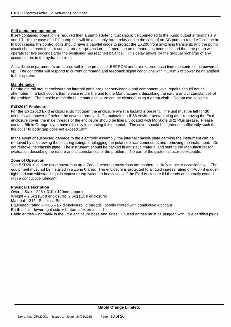
Self contained operation If self-contained operation is required then a pump starter circuit should be connected to the pump output at terminals 9 and 10. In the case of a DC pump this will be a suitably rated relay and in the case of an AC pump a rated AC contactor. In both cases, the control coils should have a parallel diode to protect the EX200 from switching transients and the pump circuit should have fuse or contact breaker protection. If operation on demand has been selected then the pump will operate for five seconds after the positioner has reached balance. This delay allows for the gradual recharge of any accumulators in the hydraulic circuit. All calibration parameters are stored within the processor EEPROM and are restored each time the controller is powered up. The controller will respond to current command and feedback signal conditions within 100mS of power being applied to the system.
Maintenance For the din rail mount enclosure no internal parts are user serviceable and component level repairs should not be attempted. If a fault occurs then please return the unit to the Manufacturers describing the nature and circumstances of the problem. The outside of the din rail mount enclosure can be cleaned using a damp cloth. Do not use solvents. EXD2010 Enclosure For the EXD2010 Ex d enclosure, do not open the enclosure whilst a hazard is present. The unit must be left for 30 minutes with power off before the cover is removed. To maintain an IP66 environmental rating after removing the Ex d enclosure cover, the male threads of the enclosure should be liberally coated with Molykote BR2 Plus grease. Please contact Bifold Orange if you have difficulty in sourcing this material. The cover should be tightened sufficiently such that the cover to body gap does not exceed 1mm In the event of suspected damage to the electronic assembly, the internal chassis plate carrying the instrument can be removed by unscrewing the securing fixings, unplugging the polarised rear connectors and removing the instrument. Do not remove the chassis plate. The instrument should be packed in antistatic material and sent to the Manufacturer for evaluation describing the nature and circumstances of the problem. No part of the system is user-serviceable.
Zone of Operation The EXD2010 can be used hazardous area Zone 1 where a hazardous atmosphere is likely to occur occasionally. The equipment must not be installed in a Zone 0 area. The enclosure is protected to a liquid ingress rating of IP66 - it is dust-tight and can withstand liquids exposure equivalent to heavy seas, if the Ex d enclosure lid threads are liberally coated with a conductive lubricant. Physical Description Overall Size – 225 x 310 x 120mm approx. Weight – 2.5kg (Ex d enclosure), 2.5kg (Ex e enclosure) Material – 316L Stainless Steel Equipment rating – IP66 – Ex d enclosure lid threads liberally coated with conductive lubricant Earth point – lower right side M6 internal/external stud Cable entries – normally in the Ex e enclosure base and sides. Unused entries must be plugged with Ex e certified plugs.

EX200 Electro-Hydraulic Actuator Positioner
Bifold Orange Limited.
Drwg. No.: ORM0001 Issue : 1 Date : 24/06/2015 Page : 11 of 20
EX200/H Hart Version - HART Revision 7 + 16 bit Manufacturers and Device ID HART Command Summary The HART signal is superimposed on the retransmitted position analog loop. Universal Commands The EX200/H supports Universal Commands Rev 7 (as of August 2007). Consult Hart Communication Foundation document HCF_SPEC-127 Universal Command Specification. Of the 22 commands, Commands 4,5 and 10 are NOT supported. Common Practice Commands The EX200/H supports Common Practice Commands Rev 8 (as of September 2006). Consult Hart Communication Foundation document HCF_SPEC-151 Common Practice Command Specification. Commands 34, 35, 49, 59, 122, 123 are supported. Private Commands The EX200/H has 2 Private Commands, a read and write pair dealing with parameters within the positioners. The body of the message is 11 bytes: Command 128 (80h) - Device Specific Command, Read positioner parameters Received Data:
None Response Data:
[0-1] INC off time H/L [2-3] Dec off time H/L [4-5] INC on time H/L [6-7] DEC on time H/L [8-9] Dead zone H/L [10] Remote enable byte
Command 129 (81h) - Device Specific Command, Write positioner parameters Received Data:
[0-1] INC off time H/L [2-3] Dec off time H/L [4-5] INC on time H/L [6-7] DEC on time H/L [8-9] Dead zone H/L [10] Remote enable byte
Response Data:
[0-1] INC off time H/L [2-3] Dec off time H/L [4-5] INC on time H/L [6-7] DEC on time H/L [8-9] Dead zone H/L [10] Remote enable byte
Bytes 0 - 7 Stepping timers The stepping (or slow operation) timers described above can be set remotely, if enabled. Each timer is set in 10mS increments; 1 second would be set as 00h 64h. Bytes 8 - 9 Positioning dead zone The positioner dead zone can be set remotely, if enabled. Each bit is approximately 0.1% of range, depending on the mechanical versus electrical range of the feedback device: a +/- 0.5% dead zone would be set at 00h 05h. Byte 10 positioner “soft switch”
EX200 Electro-Hydraulic Actuator Positioner
Bifold Orange Limited.
Drwg. No.: ORM0001 Issue : 1 Date : 24/06/2015 Page : 12 of 20
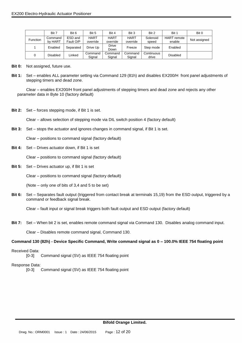
Bit 7 Bit 6 Bit 5 Bit 4 Bit 3 Bit 2 Bit 1 Bit 0
Function Command by HART
ESD and Fault O/P
HART override
HART override
HART override
Solenoid speed
HART remote enable
Not assigned
1 Enabled Separated Drive Up Drive Down
Freeze Step mode Enabled
0 Disabled Linked Command
Signal Command
Signal Command
Signal Continuous
drive Disabled
Bit 0: Not assigned, future use. Bit 1: Set – enables ALL parameter setting via Command 129 (81h) and disables EX200/H front panel adjustments of
stepping timers and dead zone.
Clear – enables EX200/H front panel adjustments of stepping timers and dead zone and rejects any other parameter data in Byte 10 (factory default)
Bit 2: Set – forces stepping mode, if Bit 1 is set. Clear – allows selection of stepping mode via DIL switch position 4 (factory default) Bit 3: Set – stops the actuator and ignores changes in command signal, if Bit 1 is set. Clear – positions to command signal (factory default) Bit 4: Set – Drives actuator down, if Bit 1 is set Clear – positions to command signal (factory default) Bit 5: Set – Drives actuator up, if Bit 1 is set Clear – positions to command signal (factory default)
(Note – only one of bits of 3,4 and 5 to be set) Bit 6: Set – Separates fault output (triggered from contact break at terminals 15,19) from the ESD output, triggered by a
command or feedback signal break. Clear – fault input or signal break triggers both fault output and ESD output (factory default) Bit 7: Set – When bit 2 is set, enables remote command signal via Command 130. Disables analog command input. Clear – Disables remote command signal, Command 130. Command 130 (82h) - Device Specific Command, Write command signal as 0 – 100.0% IEEE 754 floating point Received Data:
[0-3] Command signal (SV) as IEEE 754 floating point Response Data:
[0-3] Command signal (SV) as IEEE 754 floating point

EX200 Electro-Hydraulic Actuator Positioner
Bifold Orange Limited.
Drwg. No.: ORM0001 Issue : 1 Date : 24/06/2015 Page : 13 of 20
Specification COMMAND SIGNAL INPUT 4-20mA nominal 240R input impedance ANALOGUE POSITION OUTPUT SIGNAL 0.5-22mA can be calibrated anywhere in this range. Sourcing 12V max load 400R. Sinking 12-30V excitation FEEDBACK SIGNAL INPUT Potentiometer 3-wire, any value greater than 200R 4-20mA nominal 240R input impedance SWITCHED OUTPUTS x 5 Maximum 3A for each output (max controller volt drop at 3A = 0.27V) INSTRUMENT AND SOLENOID SUPPLY DC unit - 24Vdc (15-36V absolute maximum range) - 1.3W excluding solenoids, 55mA maximum current drawn in normal use AC Unit - 115/230V 50-60Hz – 11W USER ADJUSTMENTS DEC Button to close actuator in Manual INC Button to open actuator in Manual MAN Button to toggle auto/manual mode CAL Button to select Calibrate mode and store calibration data Timer setting DIP Switch 1 - Set stepping timers – DECREASE ON and OFF DIP Switch 2 - Set stepping timers – INCREASE ON and OFF DIP Switch 3 - No function DIP Switch 4 - No function Normal operation DIP Switch 1 - Select continuous operation on fault if in stepping mode DIP Switch 2 - No function DIP Switch 3 - Select stepping mode timers DIP Switch 4 - Select stepping mode DZ Potentiometer to set positioning dead zone - clockwise to increase CAL1 Calibration adjustment and ON time for stepping mode CAL2 Adjustment for OFF time for stepping mode INTERNAL LINKS Output sense - one position + or - must be selected for each output, even if the output is unused LINC + and - Increase solenoid sense links LDEC + and - Decrease solenoid sense links LESD + and - Auxiliary solenoid sense links LFLT + and - Fault output sense links Other function links for “Standard” Communication LK1 A Positioner default mode select LK1 B Positioner default mode select LK1 C Hydraulic pump control mode select LK1 D Fault output interlocks Other function links for “Hart” Communication LKA Hydraulic pump control mode select ENVIRONMENT Operating temperature -40ºC to +85ºC Storage temperature -40ºC to +115ºC PERFORMANCE - the following applies to the EX200 only, characteristics of the feedback element and actuator system response will have additional effects. Conversion 10 bit max normal conversion range (4-20mA) = 1 in 800. O/P switch res. +/-1 bit theoretically, modified to up to +/-5% of span by dead band. Accuracy (Theo.) 0.125% span based on conversion resolution of 1 in 800. Accuracy (actual) 0.5% span based on 25% turn down of feedback range. HART Revision 7 + 16 bit Manufacturers and Device ID
EX200 Electro-Hydraulic Actuator Positioner
Bifold Orange Limited.
Drwg. No.: ORM0001 Issue : 1 Date : 24/06/2015 Page : 14 of 20
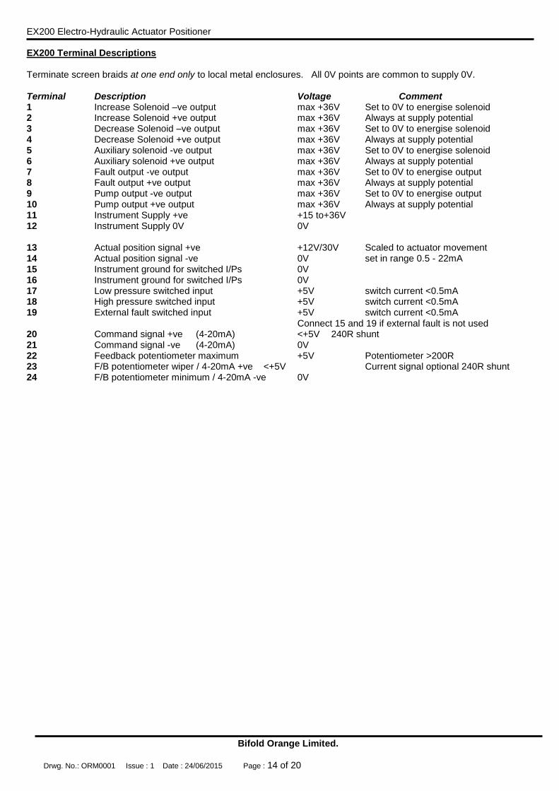
EX200 Terminal Descriptions Terminate screen braids at one end only to local metal enclosures. All 0V points are common to supply 0V. Terminal Description Voltage Comment 1 Increase Solenoid –ve output max +36V Set to 0V to energise solenoid 2 Increase Solenoid +ve output max +36V Always at supply potential 3 Decrease Solenoid –ve output max +36V Set to 0V to energise solenoid 4 Decrease Solenoid +ve output max +36V Always at supply potential 5 Auxiliary solenoid -ve output max +36V Set to 0V to energise solenoid 6 Auxiliary solenoid +ve output max +36V Always at supply potential 7 Fault output -ve output max +36V Set to 0V to energise output 8 Fault output +ve output max +36V Always at supply potential 9 Pump output -ve output max +36V Set to 0V to energise output 10 Pump output +ve output max +36V Always at supply potential 11 Instrument Supply +ve +15 to+36V 12 Instrument Supply 0V 0V 13 Actual position signal +ve +12V/30V Scaled to actuator movement 14 Actual position signal -ve 0V set in range 0.5 - 22mA 15 Instrument ground for switched I/Ps 0V 16 Instrument ground for switched I/Ps 0V 17 Low pressure switched input +5V switch current <0.5mA 18 High pressure switched input +5V switch current <0.5mA 19 External fault switched input +5V switch current <0.5mA Connect 15 and 19 if external fault is not used 20 Command signal +ve (4-20mA) <+5V 240R shunt 21 Command signal -ve (4-20mA) 0V 22 Feedback potentiometer maximum +5V Potentiometer >200R 23 F/B potentiometer wiper / 4-20mA +ve <+5V Current signal optional 240R shunt 24 F/B potentiometer minimum / 4-20mA -ve 0V

EX200 Electro-Hydraulic Actuator Positioner
Bifold Orange Limited.
Drwg. No.: ORM0001 Issue : 1 Date : 24/06/2015 Page : 15 of 20
EX200 in Din Rail Mount Enclosure Typical System Wiring diagram for a Safe Area Installation
+
-
11
12
15-36Vdc
4-20mA Command
20
21
13
14
+12V
-
4
3
7 -
8
5 -
6
Emergency
Instument Supply
22
23
24
+5V max
Wiper
0V min
Emergency
solenoid O/P
Fault O/P
Decrease
Solenoid
Command
Signal
Retransmitted
Position Signal
Feedback
Potentiometer
Decrease
Solenoid
200R or greater
Feedback Pot.
+
-
Alternative
Device4-20mA
EX200 POSITIONER
0.5-22mA Actual Position
2
Solenoid
Increase
-1Solenoid
Increase
-9
Output
Pump control
+24V10
External relay/
contactor coil
Pump supply
AC or DC
Pump fuse
Hydraulic
Pump
24V dc open drain
active when healthy
16
17
18
15
19+5V
+5V
+5V
0V
0V
External fault
High pressure switch
Low pressure switch
+24V
+24V
+24V
+24V
solenoid
+5V
0V
0V
(max. 55mA)
Connect 15 and 19 if
external fault monitoring
is not used
Feedback
Link SO - Sourcing output with 12V internal excitation
(400R max load)
Link SI - SInking output with 12-30V external excitation
EX200 Electro-Hydraulic Actuator Positioner
Bifold Orange Limited.
Drwg. No.: ORM0001 Issue : 1 Date : 24/06/2015 Page : 16 of 20
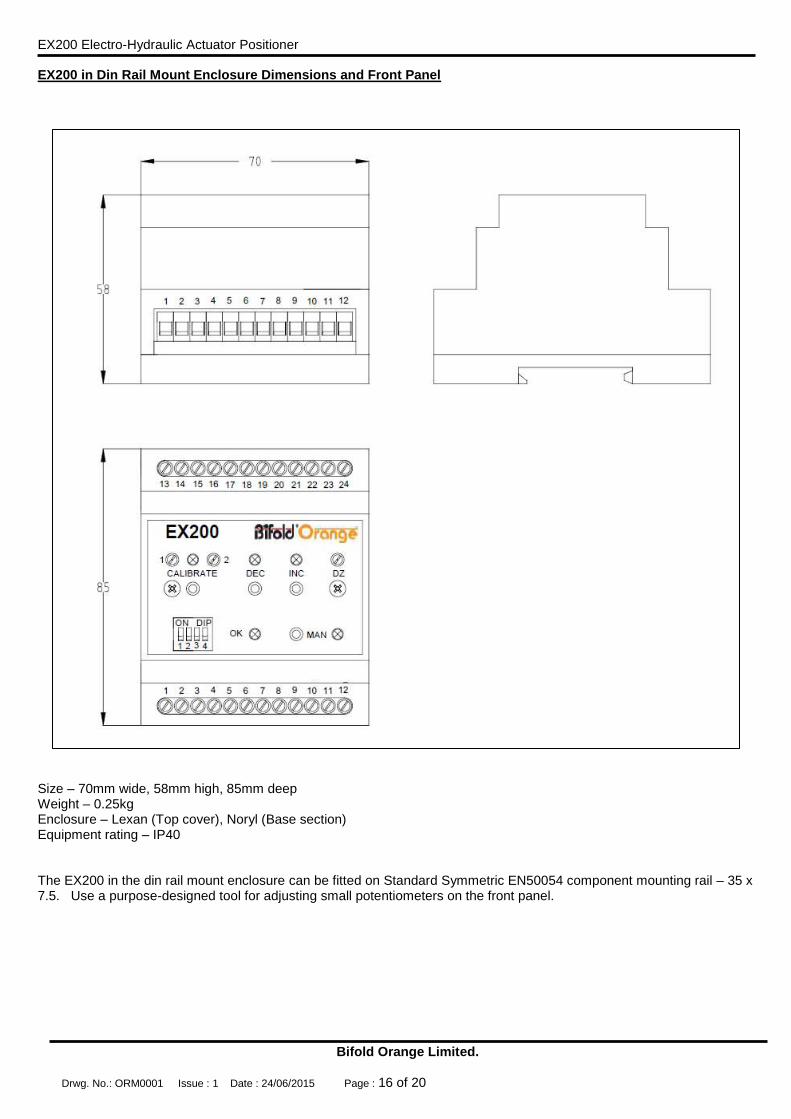
EX200 in Din Rail Mount Enclosure Dimensions and Front Panel
Size – 70mm wide, 58mm high, 85mm deep Weight – 0.25kg Enclosure – Lexan (Top cover), Noryl (Base section) Equipment rating – IP40 The EX200 in the din rail mount enclosure can be fitted on Standard Symmetric EN50054 component mounting rail – 35 x 7.5. Use a purpose-designed tool for adjusting small potentiometers on the front panel.

EX200 Electro-Hydraulic Actuator Positioner
Bifold Orange Limited.
Drwg. No.: ORM0001 Issue : 1 Date : 24/06/2015 Page : 17 of 20
EXD2010 Ex d Enclosure System Typical Layout
Typical layout drawing for information only See product specific layout drawings for precise details.

EX200 Electro-Hydraulic Actuator Positioner
Bifold Orange Limited.
Drwg. No.: ORM0001 Issue : 1 Date : 24/06/2015 Page : 18 of 20
EXD2010 Ex d Enclosure System Typical Wiring Drawing
Typical system wiring diagram for information only, shown with all feedback options. See product specific hook-up drawings for precise details.

EX200 Electro-Hydraulic Actuator Positioner
Bifold Orange Limited.
Drwg. No.: ORM0001 Issue : 1 Date : 24/06/2015 Page : 19 of 20
EX200 in EXD2010 Ex d Enclosure PCB Assembly

EX200 Electro-Hydraulic Actuator Positioner
Bifold Orange Limited.
Drwg. No.: ORM0001 Issue : 1 Date : 24/06/2015 Page : 20 of 20
EXD2010 Enclosure Assembly Manufacturer and Approvals Details The EXD2010 is manufactured and maintained solely by Bifold Fluidpower Limited: Bifold Fluidpower Ltd, Broadgate, Oldham Broadway Business Park, Chadderton, Greater Manchester, OL9 9XA United Kingdom The EXD2010 system has the following specific approvals: Name and Type Compact Ex d electro-hydraulic positioning system EXD2010 Certificate Number IECEx BAS 11.0048 EC Type Certificate Baseefa09ATEX0327 Specific Marking of Explosion Protection
DC supply Ex d IIC T6 Gb (-40ºC Ta +60ºC)
Ex tb IIIC T85ºC Db (-40ºC Ta +60ºC) IP66
AC supply Ex d IIC T5 Gb (-40ºC Ta +60ºC)
Ex tb IIIC T100ºC Db (-40ºC Ta +60ºC) IP66
IS210F FISCO Version Ex d [ia Ga] IIC T6 Gb (-40°CTamb60°C) Incorporating FISCO Field Device IS210F FISCO Instrument IECEx BAS 14.0027U Baseefa 14ATEX0059U
ATEX Directive Marking II 2 G D Notified body CE1180 Instructions for Safety The equipment must be installed by skilled electricians or instructed personnel in accordance with National Legislation and relevant technical standards. The equipment must NOT be operated in Zone 0 hazardous area. The technical data listed on the enclosure label must be observed. Changes to the design of the equipment are not permitted. The equipment shall only be operated as intended and only in an undamaged condition. The enclosure must not be opened in a hazardous atmosphere No parts of the equipment are user-serviceable. EC Declaration of Conformity
Equipment description Electro-hydraulic Positioning System EXD2010 II 2 G D DC supply version
Ex d IIC T6 Gb (-40ºC Ta +60ºC)
Ex tb IIIC T85ºC Db (-40ºC Ta +60ºC) IP66
AC supply version Ex d IIC T5 Gb (-40ºC Ta +60ºC)
Ex tb IIIC T100ºC Db (-40ºC Ta +60ºC) IP66 IS210F FISCO version
Ex d [ia Ga] IIC T6 Gb (-40ºC Ta +60ºC)
Notified body Baseefa 1180 Rockhead Business Park Staden Lane, Buxton Derbyshire SK17 9RZ United Kingdom
Harmonised Standards EN 60079-0:2012 EN 60079-1:2007 EN 60079-31:2008
Signed
Anthony G. McCormick Technical Manager Bifold Orange Bifold Fluidpower Limited
Manufacturer Bifold Fluidpower Ltd, Broadgate, Oldham Broadway Business Park, Chadderton, Greater Manchester, OL9 9XA, UK