exactly the information your subcontractor needs: desyre ... · • re specifications are mainly...
TRANSCRIPT

02.12.2011
1
Exactly the Information your
Subcontractor Needs:
DeSyRe — Decomposing
System Requirements
Dr. Birgit Penzenstadler
Universitat Polytècnica de Catalunya
Barcelona, 30. November 2011
1
Motivation: Distributed Development
• Situation:
Company assigns the
development of subsystems
to subcontractors.
• Problem:
Requirements specifications
for subsystems often lack information.
• Consequence:
Costly inquiries or later
incompatibilities.
• Reason: Requirements deduction unclear.
• State of the art:
Pragmatic handling in practice, island solutions in research.
• Result:
Missing method for the systematic deduction of subsystem requirements.
2

02.12.2011
2
Motivation: Decomposition of Requirements
• Example:
Development of a car,
assignments to subcontractors.
• Requirement: (case study)
„The velocity of the vehicle shall be
automatically adaptable to the
velocity of the preceeding vehicle.“
• Question:
How do we have to decompose
this requirement?
3
Foundation:
Examination using abstraction levels
Usage level
Logical Architecture
Technical Architecture
Subsystem
Legend:
Usage function
Logical Component
Technical Component
Abstraction Level
Relation
4

02.12.2011
3
Challenges & Contributions
System Requirements
Draft of the
System
Architecture
Adequate
Subsystem
Requirements
• Catalogue for
Decomposition
Criteria
• Interview Study
on System
Decomposition
• Patterns for Requirements
Decomposition
• Method for Implementation
• Case Studies on Applicability
and Usefulness
Contributions:
Challenges:
5
Interview Study
• Participants: 7 software and system developers from the OEMs BMW, Daimler, Audi and MAN, from the subcontractors Bosch and Siemens VDO (later on Continental) and Berghof Automation
• Purpose (template acc. to Runeson, Wohlin, Höst): Analyze requirements engineering and management for the purpose of validation with respect to the state of the practice from the point of view of the industrial developers in the context of complex systems development.
6

02.12.2011
4
Questions of the Study • System development: general approach, process,
artifacts and their relations, tools, logical subsystem architecture
• Modeling: notations, model-based RE, methods, DSLs, guidelines, roles, standard terminology
• Architecture: responsibility, criteria used, templates, guidelines, criteria and weights
• Subcontractor relationships: in-house vs. external, coordination, decision criteria, influence on architecture, documentation received (blackbox?), feature interaction, communication
• Reuse: content, extent, guidelines, with subcontractors
7
Hypotheses
• For RE specifications, the main demand
by the companies is to adhere to certain
document structures.
• A rather low degree of logical modeling is
performed during software development.
• The decomposition criteria (the draft
version of the criteria catalogue) are rated
differently, but tendencies become visible.
8

02.12.2011
5
Results • There is a defined software development process in every
company.
• RE specifications are mainly text-based, sometimes UML diagrams are used.
• The tooling is diverse, with products from, inter alia, Microsoft, Telelogic, and Vector, as well as in-house developed tools.
• The rationale, for example for the decomposition of the system, is usually not documented at all.
• A logical modeling of the system is often skipped for early modeling of the technical architecture.
• Influences from the OEM-subcontractor relationships exist in both directions and efficient communication of requirements and constraints is a challenge.
9
Results for Decomposition Criteria
10

02.12.2011
6
DeSyRe Process Overview
11
CHAPTER 5. THE DESYRE METHOD 108
The division into subsystems is based on the reference catalogue of criteria
that has been defined and explained in Chap. 3. Thesteps for thedecomposit ion
are, first , a considerat ion of the reference catalogue, then, a relat ionship analysis
of the system requirements, and finally, the division into subsystems.
5.4.1 Considerat ion of t he Reference Cat alogue
The reference catalogue of decomposit ion criteria from Chap. 3 serves as
referenceguidesuitable for different project situat ions. Therefore, it isnecessary
to analyze the relevance of the given criteria for the project at hand (Fig. 5.4).
Figure 5.4: Considerat ion of Reference Catalogue in Process DeSyRe
A customizat ion of thecatalogue isopt ional. Thecatalogueservesasgrowing
knowledge base and can be amended either during its first use in a company, or
if experience in a conducted project brought forward new criteria.
If the requirements engineer or the system architect decide to make
alterat ions to the catalogue, it is necessary to analyze the new relat ionships
and possible influences between the criteria. The relat ionships between already
ident ified criteria were discussed in Sec. 3.7.
Finally, priorit ies have to be chosen considering the opt imizat ion factors (as
described in Sec. 3.2.1) which aremost important for thesystem to bedeveloped.
These are usually given by the high priority business goals that are captured in
the art ifact Goals defined in Sec. 2.5.3.
The instance of the catalogue makes implicit knowledge explicit and helps to
take decisions on the basis of a seizable artefact with visible-made experience.
The informat ion needed for the decomposit ion is gathered via the descript ion
template described in Sec. 3.2.3, which was filled in for each criterion in the
catalogue in Sec. 3.3 – Sec. 3.6.
Running Example. The decomposit ion criteria from the reference catalogue
are instant iated and described for the driver assistance systems. Two examples,
the criteria Economics (from the category Directive Criteria) and Reliability
(from the category Quality Criteria), are given here; the complete list of the
instant iat ion can be found in Sec. 6.1.4.
Economics
• Reuse: All of the driver assistance systems have already been developed
in the previous vehicle series, so reuse is strongly expected.
System Decomposition Criteria
e.g.
[Conway] e.g.
[Rittmann]
[ISO9126]
e.g.
[Parnas]
12
• Use as Checkliste
– Constructive
– Analytical
• Evaluation: Interview-based Study Decomposition Criteria

02.12.2011
7
Description Template
13
Influences between Criteria
14

02.12.2011
8
Application of Catalogue
15
Example: Decomposition in the
Automotive Domain
• 1. The OEM specifies the complete system down to the technical architecture and assigns complete ECUs with the software to be deployed on that ECU to subcontractors.
• 2. The OEM divides the system into hardware and software and signs up different subcontractors for them.
• 3. The OEM decomposes the system according to functionality and assigns functional modules as performed in the aircraft domain, e.g. by Airbus2.
• 4. The OEM distributes a usage function over various ECUs to save resources.
16

02.12.2011
9
Example: Decomposition of Driver
Assistance Systems, Functional Feat.
17
Example: Decomposition of Driver
Assistance Systems, Comm. Req.
18

02.12.2011
10
Example: Decomposition of Driver
Assistance Systems
19
CHAPTER 5. THE DESYRE METHOD 112
Defining t he A r chi t ect ur e. Furthermore, the following rules of thumb for
defining an architecture, according to Bass et al. [BCK03, p. 16], are widely
accepted in academia and industry:
• Well-defined modules use the principles of informat ion hiding and
separat ion of concerns for their funct ional responsibilit ies.
• Well-defined interfaces per module encapsulate changeable aspects, so the
development teams can work independent ly.
• Well-known architectural tactics [BCK03, Chap. 5] help to achieve quality
at t ributes.
• Never depend on a part icular version of a tool or other commercial
product .
• Modules that producedata should beseparate from modules that consume
data.
• Parallel-processing systems need well-defined processes or tasks.
• Every task or process should be writ ten so that its assignment to a specific
processor can easily be changed.
• Use a small number of simple interact ion pat terns (= do same things in
the same way throughout).
These rules of thumb are often known in a different wording, for example as
separat ion of concerns with respect to separat ing responsibilit ies, separat ing
technical aspects and applicat ion domain, and using black boxes. Further
principles to keep in mind are reusability, maintainability, and other quality
at t ributes, as well as the so-called KISS principle (Keep It Simple and Stupid)
that captures the idea to choose the most simple feasible approach for a solut ion
when there are a couple of otherwise equal possibilit ies.
R unning Example. For the driver assistance systems, the conclusion is
to apply a decomposit ion primarily according to the ident ified services, the
user-perceived funct ionality. One usage service cluster is realized by one logical
funct ion group or logical component as depicted in Fig. 5.7.
Consequent ly, the driver assistance systems are decomposed into the
subsystems Blind Spot Detect ion, Lane Departure Warning, Adapt ive Cruise
Control, Radio Frequency Warning, Night Vision, and Driver Drowsiness
Detect ion.
Figure 5.7: Service Graph of DAS.
Overview
20
System Requirements
Draft of the
System
Architecture
Adequate
Subsystem
Requirements
• Catalogue for
Decomposition
Criteria
• Interview Study
on System
Decomposition
• Patterns for Requirements
Decomposition
• Method for Implementation
• Case Studies on Applicability
and Usefulness
Contributions:
Challenges:

02.12.2011
11
DeSyRe Process Overview
21
CHAPTER 5. THE DESYRE METHOD 113
5.5 Transit ion t o Subsyst em Requirement s
The general idea of t ransit ion from system requirements to subsystem
requirements is discussed and analyzed in Chap. 4. The applicable pat terns are
presented and illust rated with examples in Sec. 4.6.3. For some requirements
engineering art ifacts, the applicat ion differs somewhat from the plain adopt ion
of thepat terns. Therefore, theart ifactsarediscussed separately in the following.
Figure 5.8: Transit ion to Subsystem Requirements in Process DeSyRe
In Sec. 2.5.3, it wasstated that theart ifactsof thecontent categoriesContext
and Requirements may be refined on the lower levels if necessary, but their
general form would stay the same. For the transit ion of the point of view of the
overall system to thepoint of view of a subsystem, such a refinement isnecessary.
This sect ion describes the transit ion to subsystem requirements (Fig. 5.8).
Thereby, the transit ion from system level to subsystem level differs for
specific types of art ifacts as detailed in the following.
5.5.1 Cont ext
A systemat ic derivat ion and refinement of requirements for subsystems deduces
a system vision, refines the goals, deduces the stakeholders, and refines
the operat ional environment . However, as the subcontractor is usually not
intended to know all the informat ion contained in those art ifacts, some of the
informat ion (e.g., business goals) may intent ionally be omit ted in the subsystem
requirements specificat ion.
Syst em V ision. The system vision is deduced from the goals of the overall
system and the init ial decomposit ion, as the system vision in general is not
detailed enough to direct ly derive system visions for the subsystems.
Running example. The system vision of the driver assistance systems (“A
well-interrelated network of driver assistance systems shall support the driver
in demanding traffic situat ions and thereby increase the safety of the vehicle.”)
provides a rough idea, but does not allow to deduce the subsystems. Instead,
knowledge of goals and and decomposit ion allows to deduce subsystem visions,
e.g., for the Radio Frequency Warning System: “RFW supports the driver in
coping with the informat ion input from the surrounding environment by use of
radio frequency signals.”
Goals. The goals on the subsystem level are decomposed and refined for the
subsystems according to the given init ial decomposit ion. For each subsystem,
Transition from System Requirements to
Subsystem Requirements
22

02.12.2011
12
Steps for Refinement and Decomposition
23
Example: „For sensors, type
series XY has to be used.“
Example: „The DAS shall provide
visual assistance while overtaking.“
Example: „The DAS shall support
the driver in traffic.“
Example: „The console display shall
provide visual assistance during
overtaking.“
„The left rear view mirror shall
provide visual assistance during
overtaking.“
=> Constraint
Decomposition Pattern
24

02.12.2011
13
Example: Driver Assistance Systems
• Radio Frequency Warner
• Navigation System
• Adaptive Cruise Control
25
• Requirement: „In case of speeding, the driver shall be warned by display.“
• A(speedinfo, displayinfo): Information on permitted speed is available.
• A(speedinfo, RFWinfo): Information on permitted velocity is available.
• G(speedinfo, RFWinfo): Information sent whether driver is speeding.
• A(RFWinfo, displayinfo): Information available on whether driver is speeding.
• G(RFWinfo, displayinfo): Driver warned by display when indicated.
• G(speedinfo, displayinfo): Driver warned by display when indicated.
• Guarantee of Controller fulfills Assumption of Display.
In Detail: Pattern „Pipeline“
26
02.12.2011
14
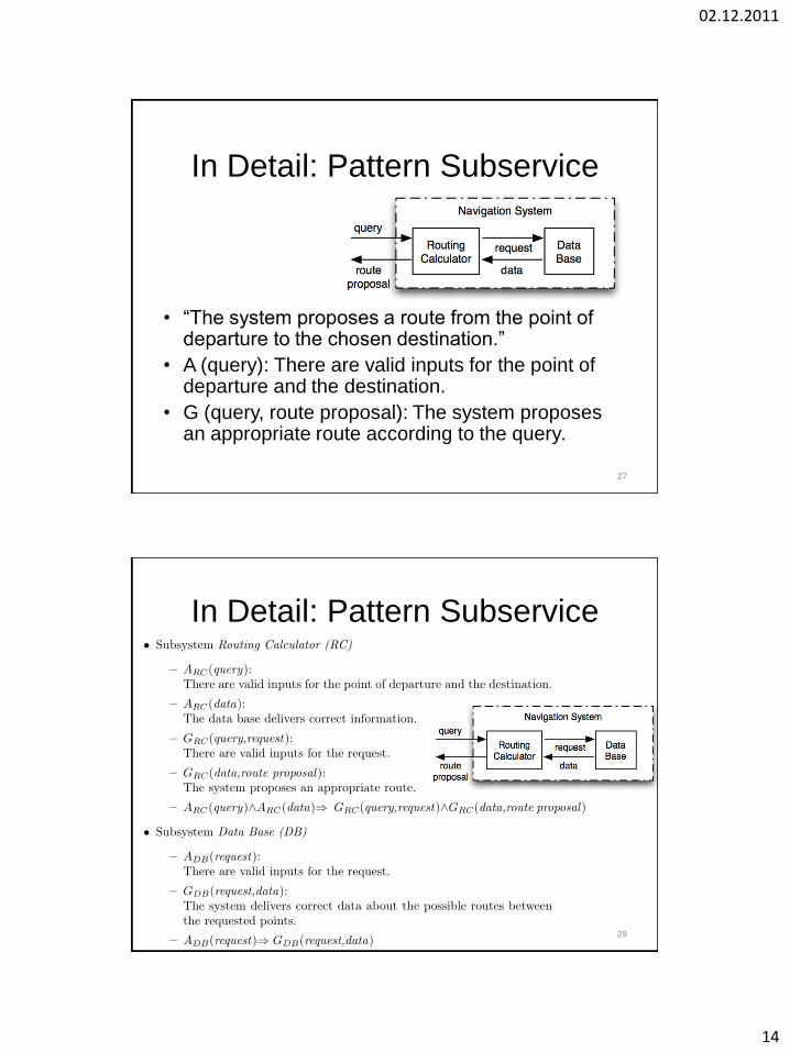
In Detail: Pattern Subservice
• “The system proposes a route from the point of departure to the chosen destination.”
• A (query): There are valid inputs for the point of departure and the destination.
• G (query, route proposal): The system proposes an appropriate route according to the query.
27
CHAPTER 4. SUBSYSTEM REQUIREMENTS 82
The pipeline is formed by the subsystems A and B. Subsystem A receives input
i , producesoutput x, which again is taken as input from subsystem B to produce
output o. For the pipeline pat tern, the decomposit ion results in the following:
• Subsystem A : AA (i , x) ⇒ GA (i , x)
• Subsystem B: AB (x, o) ⇒ GB (x, o)
• Furthermore, subsystem A sat isfies the assumpt ion of subsystem B.
Hence, the composit ion is a behavioral refinement8 of the original specificat ion:
AA (i , x) ⇒ GA (i , x) ∧ AB (x, o) ⇒ GB (x, o) ⇒ AC (i , o) ⇒ GC (i , o) (4.4)
In other words, the subsystem requirements for A and B comply with the overall
system requirement for C.
4.6.2 Subservice Decomposit ion Pat t ern
The subservice pat tern is used in the case when there is only one subsystem that
provides the interface of the system and addit ionally uses the other subsystems
to fulfill the requirement . The subservice pat tern is illust rated with an example
in the following.
Example. To illust rate the subservice decomposit ion pat tern, consider an
example from the navigat ion system, as depicted in Fig. 4.9. One system
requirement on the usage service level is:
“The system proposes a route from the point of departure to the
chosen dest inat ion.”
Theinterface isdescribed by an input channel query and an output channel route
proposal. The navigat ion system receives a query for a route proposal issued by
the driver and proposes an adequate route from the point of departure to the
dest inat ion.
Figure 4.9: Subservice Decomposit ion of an Example of the Navigat ion System.
The assumpt ion and guarantee for the navigat ion system (NS) are:
8As defined in [BS01, p. 241], a behavioral refinement relates specificat ions of t he same
syntact ic int erface, where the refined specificat ion may impose furt her requirements.
In Detail: Pattern Subservice
28
CHAPTER 4. SUBSYSTEM REQUIREMENTS 82
The pipeline is formed by the subsystems A and B. Subsystem A receives input
i , producesoutput x, which again is taken as input from subsystem B to produce
output o. For the pipeline pat tern, the decomposit ion results in the following:
• Subsystem A : AA (i , x) ⇒ GA (i , x)
• Subsystem B: AB (x, o) ⇒ GB (x, o)
• Furthermore, subsystem A sat isfies the assumpt ion of subsystem B.
Hence, the composit ion is a behavioral refinement8 of the original specificat ion:
AA (i , x) ⇒ GA (i , x) ∧ AB (x, o) ⇒ GB (x, o) ⇒ AC (i , o) ⇒ GC (i , o) (4.4)
In other words, the subsystem requirements for A and B comply with the overall
system requirement for C.
4.6.2 Subservice Decomposit ion Pat t ern
The subservice pat tern is used in the case when there is only one subsystem that
provides the interface of the system and addit ionally uses the other subsystems
to fulfill the requirement . The subservice pat tern is illust rated with an example
in the following.
Example. To illust rate the subservice decomposit ion pat tern, consider an
example from the navigat ion system, as depicted in Fig. 4.9. One system
requirement on the usage service level is:
“The system proposes a route from the point of departure to the
chosen dest inat ion.”
Theinterface isdescribed by an input channel query and an output channel route
proposal. The navigat ion system receives a query for a route proposal issued by
the driver and proposes an adequate route from the point of departure to the
dest inat ion.
Figure 4.9: Subservice Decomposit ion of an Example of the Navigat ion System.
The assumpt ion and guarantee for the navigat ion system (NS) are:
8As defined in [BS01, p. 241], a behavioral refinement relat es specificat ions of t he same
syntact ic int erface, where the refined specificat ion may impose furt her requirements.

02.12.2011
15
In Detail: General Pattern
29
CHAPTER 4. SUBSYSTEM REQUIREMENTS 85
Example. An example for the general decomposit ion case is the adapt ive
cruise cont rol (ACC) system. The ACCSystem allows the driver to set a
specific speed that the vehicle automat ically maintains. The system is depicted
in Fig. 4.11.
Figure 4.11: Decomposit ion of an Example from the ACC System.
In this example, the black box interface consists of two input channels,
revolutions provides the informat ion from the wheel sensors about the current
number of revolut ions to calculate the current speed, and setspeed provides
the informat ion from the driver about the speed he wishes to maintain. The
output channels are the display informat ion that is shown to the driver about
the maintained speed and adaptspeed is the informat ion that tells the motor
to reduce speed in order to obtain the prescribed speed. The assumpt ions and
guarantees of the ACC System are the following:
• ASys(r evolutions, setspeed):
The input revolutions delivers the current number of revolut ions from the
wheels and the input set speed delivers the speed request by the driver.
• GSys(r evolutions, setspeed, display, adaptspeed):
Theoutput display delivers feedback for thedriver according to therequest
set speed and the output adapt speed sends commands to the motor for
adapt ing the speed.
• The system requirement specificat ion for the ACC System is:
ASys(revolutions,setspeed) ⇒ GSys(revolutions,setspeed,display,adaptspeed)
The subsystems are the Motor ECU and the ACC ECU. The assumpt ions and
guarantees for the system and the subsystems are as follows:
• Subsystem Motor ECU
– AM ot or (revolutions,excess):
The informat ion about current revolutions and excess speed is
available.
– GM ot or (revolutions,excess,speed,adaptspeed):
The current speed is calculated from the revolutions and the excess
informat ion is checked whether it is necessary to adapt speed is
provided.
• Subsystem ACC ECU
• The ACC-System allows the driver to set a specific speed that the vehicle automatically maintains.
• A(revolutions,setspeed): The input revolutions delivers the current number of revolutions from the wheels and the input set speed delivers the speed request by the driver.
• G(revolutions,setspeed,display,adaptspeed): The output display delivers feedback for the driver according to the request set speed and the output adapt speed sends commands to the motor for adapting the speed.
In Detail: General Pattern
30
CHAPTER 4. SUBSYSTEM REQUIREMENTS 85
Example. An example for the general decomposit ion case is the adapt ive
cruise cont rol (ACC) system. The ACCSystem allows the driver to set a
specific speed that the vehicle automat ically maintains. The system is depicted
in Fig. 4.11.
Figure 4.11: Decomposit ion of an Example from the ACC System.
In this example, the black box interface consists of two input channels,
revolutions provides the informat ion from the wheel sensors about the current
number of revolut ions to calculate the current speed, and setspeed provides
the informat ion from the driver about the speed he wishes to maintain. The
output channels are the display informat ion that is shown to the driver about
the maintained speed and adaptspeed is the informat ion that tells the motor
to reduce speed in order to obtain the prescribed speed. The assumpt ions and
guarantees of the ACC System are the following:
• ASys(r evolutions, setspeed):
The input revolutions delivers the current number of revolut ions from the
wheels and the input set speed delivers the speed request by the driver.
• GSys(r evolutions, setspeed, display, adaptspeed):
Theoutput display delivers feedback for thedriver according to therequest
set speed and the output adapt speed sends commands to the motor for
adapt ing the speed.
• The system requirement specificat ion for the ACC System is:
ASys(revolutions,setspeed) ⇒ GSys(revolutions,setspeed,display,adaptspeed)
The subsystems are the Motor ECU and the ACC ECU. The assumpt ions and
guarantees for the system and the subsystems are as follows:
• Subsystem Motor ECU
– AM ot or (revolutions,excess):
The informat ion about current revolutions and excess speed is
available.
– GM ot or (revolutions,excess,speed,adaptspeed):
The current speed is calculated from the revolutions and the excess
informat ion is checked whether it is necessary to adapt speed is
provided.
• Subsystem ACC ECU
CHAPTER 4. SUBSYSTEM REQUIREMENTS 85
Example. An example for the general decomposit ion case is the adapt ive
cruise control (ACC) system. The ACCSystem allows the driver to set a
specific speed that the vehicle automat ically maintains. The system is depicted
in Fig. 4.11.
Figure 4.11: Decomposit ion of an Example from the ACC System.
In this example, the black box interface consists of two input channels,
revolutions provides the informat ion from the wheel sensors about the current
number of revolut ions to calculate the current speed, and setspeed provides
the informat ion from the driver about the speed he wishes to maintain. The
output channels are the display informat ion that is shown to the driver about
the maintained speed and adaptspeed is the informat ion that tells the motor
to reduce speed in order to obtain the prescribed speed. The assumpt ions and
guarantees of the ACC System are the following:
• ASys(r evolutions, setspeed):
The input revolutions delivers the current number of revolut ions from the
wheels and the input set speed delivers the speed request by the driver.
• GSys(r evolutions, setspeed, display, adaptspeed):
Theoutput display delivers feedback for thedriver according to therequest
set speed and the output adapt speed sends commands to the motor for
adapt ing the speed.
• The system requirement specificat ion for the ACC System is:
ASys(revolutions,setspeed) ⇒ GSys(revolutions,setspeed,display,adaptspeed)
The subsystems are the Motor ECU and the ACC ECU. The assumpt ions and
guarantees for the system and the subsystems are as follows:
• Subsystem Motor ECU
– AM ot or (revolutions,excess):
The informat ion about current revolutions and excess speed is
available.
– GM ot or (revolutions,excess,speed,adaptspeed):
The current speed is calculated from the revolutions and the excess
informat ion is checked whether it is necessary to adapt speed is
provided.
• Subsystem ACC ECU
CHAPTER 4. SUBSYSTEM REQUIREMENTS 86
– AA C C (speed,setspeed):
The informat ion about the current speed is available and the input
set speed delivers the speed request by the driver.
– GA C C (speed,setspeed,excess,display):
The informat ion about excess speed is delivered after comparing the
current speed to the set speed and the feedback is delivered to the
driver via display.
• Interplay of the two subsystems:
– Motor ECU calculates the current speed and sends it to ACC ECU.
– ACC ECU calculates for Motor ECU whether there is excess speed.
• Deduced behavior of the interplay:
– If the revolutions are available, Motor ECU delivers the speed.
– If the set speed is available, ACC ECU calculates excess using speed.
– In case of excess, Motor ECU issues the command adapt speed and
ACC ECU sends feedback to the driver via display.
• This complies with the overall ACC System guarantee GSys.
Hence, the decomposit ion of the example works as the original system
specificat ion of the ACC System is fulfilled.
General D escr ipt ion. In the general pat tern, both subsystems interact with
the surrounding system and provide a part of the interface, as depicted in the
white box view of the system C in Fig. 4.12.
Figure 4.12: General Decomposit ion Pat tern.
For the decomposit ion, part of the input for system C goes to subsystem A
via communicat ion channel i 1 and part of the input goes to subsystem B via
communicat ion channel i 2. The output is provided in part by subsystem A
via communicat ion channel o1 and in part by subsystem B via communicat ion
channel o2. The subsystems interact via communicat ion channels x1 and x2.
The specificat ion of the overall system requirement for C is:
AC (i 1, o1, i 2, o2) ⇒ GC (i 1, o1, i 2, o2) (4.7)
For decomposit ion, the assumpt ions and guarantees for the subsystems A and
B are:

02.12.2011
16
Deduction of nonfunctional Requirements
1. Alternative: Decompose according to System Attributes
– Example: „Display texts that shall be read on a display during driving
must not be smaller than 1cm.“
2. Alternative: Decompose with Calculation Model
– Example: „The response time of the system shall be less than half a
second for 90% system uptime.“
– Calculation models necessary, e.g., for probabilities, geometric
characteristics, correction algorithms
– Calculation partially unknown
3. Alternative: Constraint-Handling instead of Decomposition
Example: „The software may not make use of null pointers.“
31
Deduction of nonfunctional Requirements
Using the classification by Robertson and Robertson 2007 a
general guideline for the alternatives is:
1. Alternative: Decompose according to System Attributes
– look and feel requirements, cultural and political requirements, and
many usability requirements.
2. Alternative: Decompose with Calculation Model
– performance requirements, security requirements, some usability
requirements, and some legal requirements
3. Alternative: Constraint-Handling instead of Decomposition
operational and environmental requirements as well as maintainability
and support requirements, and many legal requirements.
32

02.12.2011
17
Evaluation of Applicability
• Case Study on
Driver Assistance Systems
• Application of
Decomposition criteria catalogue
and Requirements Decomposition
• Results:
– Both applicable.
– Many seemingly non-decomposable
requirements were decomposable after
refinement.
– Higher effort, but deduction
continuously traceable.
33
Requirements
Subsystem
Requirements
Evaluation of Usefulness • Presentation in software development company
for embedded systems and BIS
• Questionnaire for software engineers
• Approach evaluated positively with respect to improvement of
structuredness, completeness, traceability, integration and
reusability of requirements.
Questionnaire on usefulness of DeSyRe
Fully agree
Agree Somewhat agree Somewhat disagree
Disagree Fully disagree
Improved structuredness 1 9 1
Improved completeness 1 5 2 2
Improved traceability 2 4 2 2
Easier integration 3 1 4 2 1
Improved reusability 3 4 2
[Davis „Perceived Usefulness“ 1989]
34

02.12.2011
18
Overview – Results
35
System Requirements
Draft of the
System
Architecture
Adequate
Subsystem
Requirements
• Catalogue for
Decomposition
Criteria
• Interview Study
on System
Decomposition
• Patterns for Requirements
Decomposition
• Method for Implementation
• Case Studies on Applicability
and Usefulness
Contributions:
Challenges:
Wrapup: Decomposition of Systems and
their Requirements
Decomposition
Criteria Catalogue
Decomposition
Patterns& Method
Case study
36
02.12.2011
19
Future Work
• Case study in different application domain
• Tool support in different degrees of automation
37
Thank you!
mailto:[email protected]