examination of a prototype camera monitor system for light
TRANSCRIPT

DOT HS 812 582 October 2018
Examination of a Prototype Camera Monitor System For Light Vehicle Outside Mirror Replacement

Disclaimer
This publication is distributed by the U.S. Department of Transportation, National Highway Traffic Safety Administration, in the interest of information exchange. The opinions, findings, and conclusions expressed in this publication are those of the authors and not necessarily those of the Department of Transportation or the National Highway Traffic Safety Administration. The United States Government assumes no liability for its contents or use thereof. If trade or manufacturers’ names or products are mentioned, it is because they are considered essential to the object of the publication and should not be construed as an endorsement. The United States Government does not endorse products or manufacturers.
Suggested APA Format Citation:
Mazzae, E. N., Baldwin, G. H. S., & Andrella, A. T. (2018, October). Examination of a prototype camera monitor system for light vehicle outside mirror replacement (Report No. DOT HS 812 582). Washington, DC: National Highway Traffic Safety Administration.

i
Technical Report Documentation Page 1. Report No.DOT HS 812 582
2. Government Accession No. 3. Recipient's Catalog No.
4. Title and Subtitle Examination of a Prototype Camera Monitor System for Light Vehicle Outside Mirror Replacement
5. Report DateOctober 2018
6. Performing Organization Code NHTSA/NSR-120
7. AuthorsElizabeth N. Mazzae, National Highway Traffic Safety Administration; G. H. Scott Baldwin, and Adam T. Andrella, Transportation Research Center Inc.
8. Performing Organization Report No.
9. Performing Organization Name and Address National Highway Traffic Safety Administration Vehicle Research and Test Center P.O. Box 37 East Liberty, OH 43319
10. Work Unit No. (TRAIS)
11. Contract or Grant No.
12. Sponsoring Agency Name and AddressNational Highway Traffic Safety Administration1200 New Jersey Avenue SE. Washington, D.C. 20590
13. Type of Report and Period Covered Final Report
14. Sponsoring Agency Code
15. Supplementary NotesThe authors thank Jodi Welch of Transportation Research Center Inc. for her testing support.
16. AbstractThis report describes the examination of a prototype side camera monitor system (CMS) used in lieu of outside rearviewmirrors on a light vehicle to learn about the technology and related issues as NHTSA considers whether to revise FMVSSNo. 111 to permit such technologies as an alternative compliance option. A 2016 Audi A4 equipped with a prototypeCMS was obtained for a 4-week period and operated in daylight and darkness, in stationary and dynamic movementconditions, and dry and rainy conditions. The examination was guided both by relevant portions of existing FMVSS No.111, “Rear Visibility,” and existing and pending European standards for camera monitor systems. The examinationfocused on the quality of visibility provided by the system and comparison with traditional outside mirrors under similarconditions.
The prototype CMS exceeded the rear visibility field of view requirements of FMVSS No. 111, as is the case with most installed outside rearview mirrors on vehicles sold in the United States. However, the wider field of view presented in a surface area like that of a standard outside rearview mirror caused minification of objects rendering them narrower and more difficult to discern. While display glare caused by sunlight was a foreseen issue, only minimal such glare was observed. CMS image clarity was good, comparable to that of outside rearview mirrors. Visibility was especially good during dusk and dawn conditions when the displayed areas appeared brighter than would be seen with traditional mirrors.
Aspects of the prototype system’s performance that may be cause for concern included excessive blooming and lens flare from headlights of other traffic at night that exceeded that permitted in the related ISO standard. Other issues included image obscuration due to water droplets remaining on the camera lens while driving and high display brightness that in dark driving conditions may glare and annoy drivers, as well as make discerning of forward objects more difficult. It is currently unclear whether these issues may be adequately remedied in a cost-effective manner.
One significant unknown with this new technology is how well drivers may acclimate to the new display type and typically lower, interior mounting location for the electronic displays. The prototype CMS display viewing angle was approximately 12° lower than a traditional mirror location, which may be somewhat disorienting for drivers at least for some initial period.
17. Key Words 18. Distribution Statement Document is available to the public from the National Technical Information Service, www.ntis.gov
19. Security Classif. (of this report) Unclassified
20. Security Classif. (of this page) Unclassified
21. No. of Pages 67
22. Price
Form DOT F 1700.7 (8-72) Reproduction of completed page authorized

ii
TABLE OF CONTENTS
LIST OF FIGURES ...................................................................................................................... iv
LIST OF TABLES ....................................................................................................................... vii
EXECUTIVE SUMMARY .............................................................................................................. 1
1.0 INTRODUCTION .................................................................................................................. 3
2.0 BACKGROUND AND OBJECTIVES .................................................................................. 4
2.1 Existing Requirements ................................................................................................... 4
2.2 Related Petitions ............................................................................................................ 4
2.3 Noteworthy Issues .......................................................................................................... 5
2.4 Objective of System Examination .................................................................................. 6
3.0 DESCRIPTION OF SYSTEM EXAMINED ........................................................................... 7
3.1 Exterior Photos of the Prototype Side Camera Monitor System .................................... 7
3.2 Interior Photos of the Side-View Camera Monitor System Displays ............................ 10
3.3 Comparison Vehicle With Traditional Outside Mirrors ................................................. 11
4.0 METHOD ............................................................................................................................ 13
4.1 Test Procedures ........................................................................................................... 13
4.2 Test Locations .............................................................................................................. 13
4.3 Instrumentation ............................................................................................................ 13
4.4 Test Objects ................................................................................................................. 13
4.5 Vehicle Preparation ...................................................................................................... 14
5.0 RESULTS .......................................................................................................................... 15
5.1 Field of View Measurement .......................................................................................... 15
5.2 Visibility of Test Objects in Daytime and Nighttime Conditions .................................... 18
5.3 Image Quality Examination .......................................................................................... 27
5.4 Downward Viewing Angle, Side CMS Display Versus Traditional Mirrors ................... 31
5.5 CMS Display Brightness in Dark Driving Conditions .................................................... 32
5.6 Observations Based on Driving the CMS-Equipped Vehicle on Public Roads ............ 34
6.0 SUMMARY OF OBSERVATIONS AND ADDITIONAL DISCUSSION .............................. 40
6.1 Summary of Observations ............................................................................................ 40
6.2 Additional Issue That May Impact Side CMS Usability: Display Viewing Problems With Polarized Eyeglass/Sunglass Lenses .................................................. 40
iii
7.0 SUMMARY ......................................................................................................................... 41
8.0 REFERENCES ................................................................................................................... 43
9.0 APPENDIX ......................................................................................................................... 44
9.1 Images of Test Vehicles ............................................................................................... 44
9.2 CMS Versus Mirror Image Comparison Photos ........................................................... 46

iv
LIST OF FIGURES
Figure 1. Photos Showing Cameras of the Prototype Side Camera Monitor System ............... 7
Figure 2. Passenger Side Camera Housing .............................................................................. 8
Figure 3. Passenger Side Camera ............................................................................................ 8
Figure 4. Camera Housing (Passenger Side), Top-Down View With Ruler in Image ............... 9
Figure 5. Camera Housing (Passenger Side), With Ruler in Image .......................................... 9
Figure 6. Driver-Side Interior Display, Driver’s Viewpoint, ISO Grid in View ........................... 10
Figure 7. Passenger-Side Interior Display, Driver’s Viewpoint, ISO Grid in View ................... 11
Figure 8. Photos of the Outside Rearview Mirrors on a 2017 Audi A4 .................................... 12
Figure 9. Driver-Side Outside Rearview Mirror ....................................................................... 12
Figure 10. Posable Child Mannequin Test Object, Front View .................................................. 14
Figure 11. Fields of View for Prototype Side Rearview CMS and Original Equipment Mirrors .................................................................................................... 16
Figure 12. Direct Vision Field-of-View for the 2017 Audi A4 Test Vehicle ................................ 17
Figure 13. Illustration of Child Mannequin Test Object Positions With Respect to the CMS Test Vehicle Location. ..................................................................................... 19
Figure 14. Illustration of Sedan Test Object Positioned 10 Feet Aft of CMS Test Vehicle Front Bumper. ............................................................................................. 20
Figure 15. Sedan Positioned 15 Feet (4.57 m) Aft of Front Bumper, as Viewed With Side CMS (top) and Mirrors (bottom) on Driver (left) and Passenger Side (right) ............ 22
Figure 16. Child Mannequin Positioned 82.0 Feet (25 m) Aft of Rear Bumper, as Viewed With Side CMS (top) and Mirrors (bottom) on Driver (left) and Passenger Side (right) ............................................................................................. 23
Figure 17. Sedan Positioned 16.4 Feet (5 m) Aft of Rear Bumper at Night Time, as Viewed With Side CMS (top) and Mirrors (bottom) on Driver (left) and Passenger Side (right) ............................................................................................. 24
Figure 18. Child Mannequin Positioned 5 Feet (1.52 m) Aft of Rear Bumper, at Night Time as Viewed With Side CMS on Driver (left) and Passenger Side (right) ........... 24
Figure 19. Posable Child Mannequin in Sunny Test Conditions, Glare/Reflection in CMS Display ............................................................................................................ 25
Figure 20. Sedan Test Object in Sunny Test Conditions, Glare/Reflection in CMS Display ..... 25
Figure 21. Posable Child Mannequin in Sunny Test Conditions, Minimal Glare/Reflection in CMS Display .............................................................................. 26
Figure 22. Sedan Test Object in Sunny Test Conditions, Minimal Glare/Reflection in CMS Display ............................................................................................................ 26
Figure 23. Near and Far Chessboard in Lighted Environment as Viewed With Driver (left) and Passenger Side (right) CMS Displays ............................................ 28
Figure 24. Driver (left) and Passenger Side (right) CMS Displays Showing Near (top) and Far (bottom) Chessboard, Dark Environment, Vehicle Tail Lights On ..................... 29

v
Figure 25. Near Chessboard in Dark Environment With Vehicle Tail Lights Off as Viewed With Driver (left) and Passenger Side (right) CMS Displays ....................... 29
Figure 26. Near and Far Chessboard in Lighted Environment as Viewed With Driver (left) and Passenger Side (right) Mirrors ....................................................... 30
Figure 27. Near and Far Chessboard in Dark Environment as Viewed With Driver (left) and Passenger Side (right) Mirrors ....................................................... 30
Figure 28. Downward Viewing Angle, CMS Display Versus Mirror ........................................... 31
Figure 29. Side CMS Displays, Viewed From 50th Percentile Male Driver’s Viewpoint ............ 31
Figure 30. Measured Illuminance, CMS Displays Versus Mirrors ............................................. 33
Figure 31. Photo of Passenger-Side CMS Display and Portion of Forward Windshield View, Highlighting the Disparity in Apparent Ambient Illumination at Dusk ....................... 35
Figure 32. Photo of Side CMS Displays in Unlit Area, Vehicle Taillights Only .......................... 36
Figure 33. CMS Display Versus Mirror, Vehicle Behind in Adjacent Lane ................................ 37
Figure 34. CMS Display Versus Mirror, Multiple Vehicles Behind in Adjacent Lane ................. 37
Figure 35. CMS Display Versus Mirror, Taillights of Other Traffic ............................................. 37
Figure 36. Photo of Passenger-Side CMS Display in Rainy Conditions ................................... 38
Figure 37. Driver-Side CMS Display, Blooming and Lens Flare ............................................... 39
Figure 38. Image of Vehicle Headlights Passing on the Left at Night With Blooming Visible in CMS Display ............................................................................. 39
Figure 39. Audi A4, Front and Rear Views ................................................................................ 44
Figure 40. Audi A4, Four Three-Quarter Views ......................................................................... 44
Figure 41. Audi With Mirrors, Front and Rear Views ................................................................. 45
Figure 42. Audi With Mirrors, Four Three-Quarter Views .......................................................... 45
Figure 43. Sedan Positioned 5 Feet (1.52 m) Aft of Front Bumper, as Viewed With Side CMS (top) and Mirrors (bottom) on Driver (left) and Passenger Side (right) ............ 46
Figure 44. Sedan Positioned 10 Feet (3.05 m) Aft of Front Bumper, as Viewed With Side CMS (top) and Mirrors (bottom) on Driver (left) and Passenger Side (right) ............ 47
Figure 45. Sedan Positioned 15 Feet (4.57 m) Aft of Front Bumper, as Viewed With Side CMS (top) and Mirrors (bottom) on Driver (left) and Passenger Side (right) ............ 47
Figure 46. Sedan Positioned 5 Feet (1.52 m) Aft of Rear Bumper, as Viewed With Side CMS (top) and Mirrors (bottom) on Driver (left) and Passenger Side (right) ............ 48
Figure 47. Sedan Positioned 16.4 Feet (5 m) Aft of Rear Bumper, as Viewed With Side CMS (top) and Mirrors (bottom) on Driver (left) and Passenger Side (right) ............ 48
Figure 48. Sedan Positioned 32.8 Feet (10 m) Aft of Rear Bumper, as Viewed With Side CMS (top) and Mirrors (bottom) on Driver (left) and Passenger Side (right) ............ 49
Figure 49. Sedan Positioned 82.0 Feet (25 m) Aft of Rear Bumper, as Viewed With Side CMS (top) and Mirrors (bottom) on Driver (left) and Passenger Side (right) ............ 49
Figure 50. Child Mannequin Positioned 5 Feet (1.52 m) Aft of Rear Bumper, as Viewed With Side CMS (left) and Mirrors (right) on Passenger Side ....................... 50

vi
Figure 51. Child Mannequin Positioned 16.4 Feet (5 m) Aft of Rear Bumper, as Viewed With Side CMS (top) and Mirrors (bottom) on Driver (left) and Passenger Side (right) ............................................................................................. 51
Figure 52. Child Mannequin Positioned 32.8 Feet (10 m) Aft of Rear Bumper, as Viewed With Side CMS (top) and Mirrors (bottom) on Driver (left) and Passenger Side (right) ............................................................................................. 51
Figure 53. Child Mannequin Positioned 82.0 Feet (25 m) Aft of Rear Bumper, as Viewed With Side CMS (top) and Mirrors (bottom) on Driver (left) and Passenger Side (right) ............................................................................................. 52
Figure 54. Sedan Positioned 5 Feet (1.52 m) Aft of Front Bumper at Night Time, as Viewed With Side CMS (left) and Mirrors (right) on Passenger Side ....................... 53
Figure 55. Sedan Positioned 10 Feet (3.05 m) Aft of Front Bumper at Night Time, as Viewed With Side CMS (left) and Mirrors (right) on Passenger Side ....................... 53
Figure 56. Sedan Positioned15 Feet (4.57 m) Aft of Front Bumper at Night Time, as Viewed With Side CMS (top) and Mirrors (bottom) on Driver (left) and Passenger Side (right) ............................................................................................. 54
Figure 57. Sedan Positioned 5 Feet (1.52 m) Aft of Rear Bumper at Night Time, as Viewed With Side CMS (top) and Mirrors (bottom) on Driver (left) and Passenger Side (right) ............................................................................................. 54
Figure 58. Sedan Positioned 16.4 Feet (5 m) Aft of Rear Bumper at Night Time, as Viewed With Side CMS (top) and Mirrors (bottom) on Driver (left) and Passenger Side (right) ............................................................................................. 55
Figure 59. Sedan Positioned 32.8 Feet (10 m) Aft of Rear Bumper at Night Time, as Viewed With Side CMS (top) and Mirrors (bottom) on Driver (left) and Passenger Side (right) ............................................................................................. 55
Figure 60. Sedan Positioned 82.0 Feet (25 m) Aft of Rear Bumper at Night Time, as Viewed With Side CMS (top) and Mirrors (bottom) on Driver (left) and Passenger Side (right) ............................................................................................. 56
Figure 61. Child Mannequin Positioned 5 Feet (1.52 m) Aft of Rear Bumper, at Night Time as Viewed With Side CMS on Driver (left) and Passenger Side (right) ............................................................................................. 56
Figure 62. Child Mannequin Positioned 16.4 Feet (5 m) Aft of Rear Bumper, at Night Time as Viewed With Side CMS (top) and Mirrors (bottom) on Driver (left) and Passenger Side (right) .................................................................... 57
Figure 63. Child Mannequin Positioned 32.8 Feet (10 m) Aft of Rear Bumper, at Night Time as Viewed With Side CMS (left) and Mirror (right) on Driver Side ............................................................................................................... 57
Figure 64. Child Mannequin Positioned 82.0 Feet (25 m) Aft of Rear Bumper, at Night Time as Viewed With Side CMS on Driver (left) and Passenger Side (right) ............................................................................................. 57
vii
LIST OF TABLES
Table 1. Outline of Tests of Objects in Field of View, Adjacent Lane Scenarios ................... 18
Table 2. Test Object Visibility by Location and System (CMS Versus Mirrors) ...................... 21
Table 3. Measurements for Illuminance at the Driver’s Eye Midpoint for CMS Displays Versus Mirrors ........................................................................................... 33
1
EXECUTIVE SUMMARY
Introduction
Camera monitor systems (CMS) for side visibility are being considered by manufacturers of both light and heavy vehicles as an alternate means to provide drivers with the field of view currently afforded by mirrors. Two manufacturers, one of light and another of heavy vehicles, have separately petitioned the National Highway Traffic Safety Administration requesting that Federal Motor Vehicle Safety Standard (FMVSS) No. 111 be modified to permit technologies other than mirrors to be used to meet visibility requirements currently specified for provision by outside rearview mirrors. FMVSS No. 111 is titled “Rear Visibility” and contains specific requirements for equipping light vehicles with “inside” and “outside” rearview mirrors to aid driver vision. The prevalent technology under consideration is a camera and electronic visual display (i.e., monitor) system. Such a system replaces outside mirrors with small cameras in the same locations that transmit video images to interior-mounted electronic visual displays.
To inform NHTSA’s decision as to whether to pursue such a regulation modification to permit technologies other than mirrors for compliance with FMVSS No. 111, information was gathered through examination of a prototype camera-based system. Related issues and anticipated impacts, both positive and negative, of such a change were considered. The issues that should be considered include the following.
• Existing Industry Standards • Field of View • Image Quality • Image Display Locations and Driver Acclimation • Component Durability and Reliability • Test Procedure Development
This research touched on all those issues except component durability and reliability. Objective The objective of this effort was to gather information regarding side camera monitor system design, performance, and conceivable issues associated with the replacement of traditional vehicle outside rearview mirrors with electronic side camera monitor systems. A prototype camera-based side vision system-equipped vehicle was examined to gather information on system performance in light, dark, dry, and rainy conditions. The examination focused on the quality of visibility provided by the system and comparison with traditional outside mirrors under similar conditions. The examination was guided both by relevant portions of existing FMVSS No. 111 and existing and pending European standards for vehicle camera monitor systems. At the time of this work, the International Organization for Standardization (ISO) had enacted a standard and the United Nations Economic Commission for Europe (ECE) had a draft standard. A subset of the issue points above was selected for examination in this research and evaluated to determine whether existing standards and any applicable test procedures might be suitable for FMVSS use.

2
Summary
The prototype CMS exceeded the rear visibility field of view requirements of FMVSS No. 111, as is the case with most installed outside rearview mirrors on vehicles sold in the United States. However, the wider field of view presented in a surface area like that of a standard outside rearview mirror caused minification of objects rendering them narrower and more difficult to discern. While display glare caused by sunlight was a foreseen issue, only minimal such glare was observed. CMS image clarity was good, comparable to that of outside rearview mirrors. Visibility was especially good during dusk and dawn conditions when the displayed areas appeared brighter than would be seen with traditional mirrors. One major unknown with this new technology is how well drivers may acclimate to the new display type and typically lower, interior mounting location for the electronic displays. The prototype CMS examined in this testing presented its side rearview image via a visual display located at the upper forward corner of the front door. The associated visual angle for a driver looking at this display would be approximately 12 degrees lower than for a traditional outside rearview mirror location, which may be somewhat disorienting for drivers at least for some initial period of time. Another potential issue was perceived “high” display illuminance witnessed during conditions in which researchers were driving at night. Aspects of the prototype system’s performance that may be cause for concern included excessive blooming and lens flare from headlights of other traffic at night that exceeded that permitted in the related ISO standard. Other issues included image obscuration due to water droplets remaining on the camera lens while driving and high display brightness that may glare and annoy drivers in dark driving conditions, as well as make discerning of forward objects more difficult. It is currently unclear whether these issues may be adequately remedied in a cost-effective manner.
Other unknowns regarding this new technology include system reliability and whether quality video image availability would be sufficient to match performance of traditional mirrors. Will blooming, glare, water on lens combine to result in a substantial portion of time when a usable image is not available? Based on these observations, the following questions are posed for future designs:
• Can night mode be improved to have lower display luminance? • Can image obscuration from water droplets be remedied? • Can following vehicle headlight blooming be reduced? • Is there an optimal downward viewing angle for such displays that maximizes drivers’
comfort and situational awareness?

3
1.0 INTRODUCTION
Camera monitor systems (CMS) are being considered by manufacturers of both light and heavy vehicles as an alternate means to provide drivers with the field of view currently afforded by outside rearview mirrors. The prevalent alternative technology under consideration is a video-based system that replaces outside mirrors with small cameras that transmit video images to interior-mounted electronic visual displays (i.e., monitors).
Mirrors have been standard fixtures on cars for many years. The first vehicle rearview mirrors appeared around 1906. Driver-side outside mirrors were standard years before passenger-side outside mirrors became commonplace sometime around 1980. Making a change to such a crucial means for drivers to acquire information about what is around their vehicle and situational awareness cannot be done hastily and without considering the effects on safety.
To make an informed decision as to whether to pursue a regulation modification to permit technologies other than mirrors for compliance with Federal Motor Vehicle Safety Standard (FMVSS) No. 111 [1], NHTSA must carefully analyze related issues and anticipated impacts, both positive and negative, of such a change. The issues that must be addressed before moving forward with allowing alternatives to mirrors include the following.
• Existing Industry Standards • Field of View • Image Quality • Image Display Locations and Driver Acclimation • Component (e.g., Camera) Durability and Reliability • Test Procedure Development

4
2.0 BACKGROUND AND OBJECTIVES
2.1 Existing Requirements
FMVSS No. 111 [1] is titled “Rear Visibility” and contains specific requirements for equipping light vehicles with “inside” and “outside” rearview mirrors to aid driver vision. The outside rearview mirror related requirements are as follows:
• S5.2.1 Field of view. Each passenger car shall have an outside mirror of unit magnification. The mirror shall provide the driver a view of a level road surface extending to the horizon from a line, perpendicular to a longitudinal plane tangent to the driver's side of the vehicle at the widest point, extending 2.4m out from the tangent plane 10.7m behind the driver's eyes, with the seat in the rearmost position. The line of sight may be partially obscured by rear body or fender contours. The location of the driver's eye reference points shall be those established in Motor Vehicle Safety Standard No. 104 (§ 571.104) or a nominal location appropriate for any 95th percentile male driver.
• S5.3 Outside rearview mirror passenger's side. Each passenger car whose inside rearview mirror does not meet the field of view requirements of S5.1.1 shall have an outside mirror of unit magnification or a convex mirror installed on the passenger's side. The mirror mounting shall provide a stable support and be free of sharp points or edges that could contribute to pedestrian injury. The mirror need not be adjustable from the driver's seat but shall be capable of adjustment by tilting in both horizontal and vertical directions.
2.2 Related Petitions
Manufacturers of both light and heavy vehicles are interested in the possibility of using alternative electronic technologies to provide drivers with the field of view currently afforded by mirrors. Two manufacturers, one of light and another of heavy vehicles, have separately petitioned NHTSA requesting that FMVSS No. 111 be modified to permit technologies other than mirrors to be used to meet side visibility requirements. The prevalent alternative technology under consideration is a camera and electronic visual display system. Such a system replaces outside mirrors with small cameras in the same locations that transmit video images to interior-mounted electronic displays.
A petition submitted by the Alliance of Automobile Manufacturers and Tesla in March 2014 requested NHTSA to “update FMVSS No. 111 to allow the use of camera-based rear and/or side vision systems as a compliance option for meeting the performance requirements specified for rearview mirrors for each location where conventional mirrors are currently required or permitted.” The petition mentioned the Honda “LaneWatch” system, which presents a center-stack based view of the area to the right side of a vehicle when the right turn signal is activated. The petition also noted that Volkswagen has released in Europe a test fleet of XL1 model vehicles fitted with rear and side-view camera systems.
A subsequent petition submitted in April 2015 by Daimler Trucks North America asked NHTSA to revise FMVSS No. 111 to permit the use of CMS as an alternative compliance option to the use of rearview mirrors for heavy-duty trucks.
Both petitions indicated that camera monitor systems could meet existing FMVSS No. 111 performance requirements while offering improved fuel economy.

5
2.3 Noteworthy Issues
To make an informed decision as to whether to pursue the requested regulation modification, NHTSA must carefully analyze related issues and anticipated impacts, both positive and negative, of such a change. The primary issues that must be examined before moving forward with allowing alternatives to mirrors include the following.
Existing Industry Standards
• The International Organization for Standardization (ISO) has a standard for vehicle-based camera technologies, ISO 16505:2015, Road Vehicles – Ergonomic and performance aspects of Camera Monitor Systems – Requirements and test procedures [2], which would cover the replacement of outside rearview mirrors with camera monitor systems. Similarly, the United Nations Economic Commission for Europe (ECE) has its Regulation No. 46, "Uniform provisions concerning the approval of devices for indirect vision and of motor vehicles with regard to the installation of these devices" [3], which was updated in 2016. If these standards are judged to be sufficiently thorough and safety-focused, it may be possible to harmonize those requirements into FMVSS No. 111. However, such a decision cannot be made without first testing representative camera and display technologies to assess the related specifications.
Field of View
• Alternative technologies used to provide the field of view traditionally provided by mirrors would likely need different test procedures to ensure that the same or an improved area of visibility is provided to the driver. These test procedures do not exist or they don’t address safety issues such as unit magnification.
• Some companies have stated that providing drivers with expanded views would be advantageous for drivers. Research is needed to confirm that providing a wider-than-required view does not lead to increased eye glance durations away from the forward roadway or present challenges for image quality and usability.
Image Quality
• Any side-view image presented via electronic visual display should have good image quality. Minimization of any image distortion is important to providing useful visibility to drivers. For example, past NHTSA research identified image blooming as an issue when driving at night. Performance requirements and test procedures that evaluate image blooming and other display aberrations, and ensure that image quality is sufficient to support safe driving, have not been developed.
Image Display Locations and Driver Acclimation
• Outside rearview mirrors displaying the areas to the sides of a vehicle have historically been geometrically constrained in terms of location to provide the required field of view. However, ISO’s International Standard 16505 [2] and the United Nations ECE’s pending revision to its Regulation No. 46 [3] both allow flexibility in the location of the right-side image – anywhere to the right of the driver. NHTSA is not aware of any research that would support this flexibility in right side image placement or location of the image away from the traditional mirror location. Industry prototypes seen in recent years have used a variety of CMS display locations (e.g., at one or both A-pillars near the traditional location of outside rearview mirrors, in the center stack, in the inside rearview mirror, and some combinations of these locations). The impact of these different image locations on driver performance is not known. However, industry-sponsored research to be carried out by the

6
Virginia Tech Transportation Research Institute (VTTI) will hopefully provide information on these issues.
• With electronic visual displays, glare from sunlight and other vehicles’ headlights may cause a safety issue. An assessment of potential glare-causing factors and, if warranted, potential ways to mitigate glare are needed to ensure that useful images would be provided to drivers for the greatest range of conditions possible.
• We are not aware of any data that exist to demonstrate that replacing outside rearview mirrors with camera-based electronic displays will not negatively impact light and heavy vehicle driver behavior, situational awareness while driving, and overall safety in the United States.
Camera Durability and Reliability
• As a replacement device for external mirrors, an assessment of the anticipated rate of failure of these cameras in anticipated external mounting locations is needed.
• NHTSA has observed condensation in cameras mounted on the underside of the outside rearview mirrors of recent model year production vehicles resulting in image obscuration. Performance specifications and test procedures for ensuring adequate real-world weatherproof performance of side-mounted cameras have not been developed.
• Depending on the mounting location, cameras may be subject to environmentally-caused lens obstructions such as dirt or rain drops. Test procedures that simulate these conditions and their associated performance requirements have not been developed to evaluate whether the camera is providing a useful image.
Test Procedure Development
• Test procedures that accurately assess systems’ performance regarding the above-listed issues are needed.
2.4 Objective of System Examination
The objective of this effort was to gather information regarding side-view camera monitor system design, performance, and conceivable issues associated with the replacement of traditional vehicle outside mirrors with electronic camera monitor systems. A prototype camera-based side vision system installed on a sedan was examined to gather information on system performance in light, dark, dry, and rainy conditions. The examination focused on the quality of visibility provided by the system and comparison with traditional outside mirrors under similar conditions. The examination was guided both by relevant portions of existing FMVSS No. 111 and existing and pending European standards for camera monitor systems. At the time of this work, the ISO had enacted a standard and the ECE had a draft standard. A subset of the issue points above was selected for examination in this research and evaluated to determine whether existing standards and any applicable test procedures might be suitable for FMVSS use.
7
3.0 DESCRIPTION OF SYSTEM EXAMINED
A 2016 Audi A4 outfitted with a prototype side-view camera monitor system was examined. For comparison purposes, a 2017 Audi A4 equipped with original equipment outside mirrors was subjected to the same assessment steps.
Images of each vehicle are provided in the appendix of this report. Images of the side-view camera monitor system and comparison outside mirrors are shown in the following sections, along with a description containing the dimensions of the side-view CMS and outside mirrors.
3.1 Exterior Photos of the Prototype Side Camera Monitor System
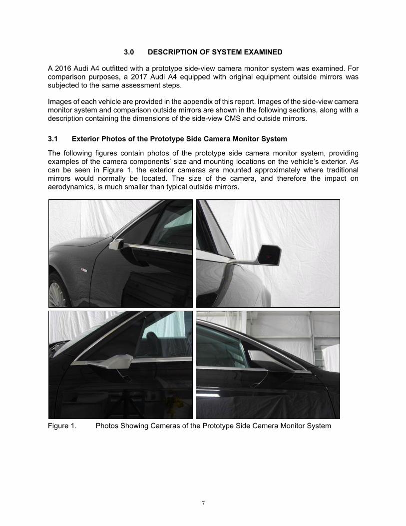
The following figures contain photos of the prototype side camera monitor system, providing examples of the camera components’ size and mounting locations on the vehicle’s exterior. As can be seen in Figure 1, the exterior cameras are mounted approximately where traditional mirrors would normally be located. The size of the camera, and therefore the impact on aerodynamics, is much smaller than typical outside mirrors.
Figure 1. Photos Showing Cameras of the Prototype Side Camera Monitor System

8
The following two figures provide a close-up look at the design and shape of the camera housing on the passenger side of the vehicle.
Figure 2. Passenger Side Camera Housing
Figure 3. Passenger Side Camera

9
The following two figures provide a close-up view of the camera housing with a ruler included in the image to provide an idea of the length and width of the camera housing.
Figure 4. Camera Housing (Passenger Side), Top-Down View With Ruler in Image
Figure 5. Camera Housing (Passenger Side), With Ruler in Image

10
3.2 Interior Photos of the Side-View Camera Monitor System Displays
The driver and passenger side CMS displays were located at the leading edge of the corresponding door panels and had overhanging trim above to help block sunlight from striking the displays. Figures 6 and 7 contain photos of the driver and passenger side interior CMS displays, respectively, as viewed from the 50th percentile male driver’s viewpoint. The CMS display shows an image of an ISO grid (chessboard chart) in the field of view to highlight the display location and clarity. See section 5.3 for more information on the ISO grid.
Figure 6. Driver-Side Interior Display, Driver’s Viewpoint, ISO Grid in View

11
Figure 7. Passenger-Side Interior Display, Driver’s Viewpoint, ISO Grid in View
Both CMS displays were the same size. The approximate dimensions of the driver-side display were as follows. • From top left corner to top right corner: 4.45 inches (11.3 cm) • From top right corner to bottom right corner: 2.82 inches (7.16 cm) • From bottom right corner to trim line on bottom left curve: 3.90 inches (9.91 cm) • From trim line on bottom left curve to top left corner: 2.39 inches (6.07 cm)
3.3 Comparison Vehicle With Traditional Outside Mirrors
Figure 8 shows images of the comparison vehicle equipped with traditional mirrors. The dimensions of the mirrors were approximately 7 inches (17.8 cm) at the widest point and 4.5 inches (11.4 cm) at the highest point. A close-up view of the mirror housing with a tape measure included in the image is provided in the following figure to provide an idea of the size of the mirror and mirror housing for comparison with the CMS camera unit.

12
Figure 8. Photos of the Outside Rearview Mirrors on a 2017 Audi A4
Figure 9. Driver-Side Outside Rearview Mirror

13
4.0 METHOD
This section describes the test procedures used in assessing the prototype side camera monitor system, and any specific equipment that may have been used to perform such procedures.
The ISO 16505:2015 and ECE Regulation No. 46:2016 standards were reviewed for specific test procedures that could be applied using available equipment and facilities.
4.1 Test Procedures
Tests performed included:
• System Field-of-View (FOV) measurement
• Visibility of test objects in daytime and nighttime conditions
• CMS image quality examination
• Display viewing angle
• CMS image brightness in dark conditions
• Driving on public roads in daylight and darkness to observe system operation and use
Tests were performed as appropriate, given the operating conditions of each procedure being implemented, with the test vehicle either stationary or moving to assess system performance. For better clarity, the specific procedures for each test are described along with the results of each test in the results section of this report since various test procedures were used for assessing system performance in this effort.
4.2 Test Locations
The side visibility system was assessed in a variety of environments, including public roads, laboratories, and test track facilities. The system was assessed in both day and night conditions, and in conditions with various levels of precipitation.
4.3 Instrumentation
A digital camera was used to capture photographs of each test vehicle. Dynamic test trials were recorded in digital video format to document the dynamic test scenario.
4.4 Test Objects
Various test objects were used in this effort to illustrate the performance of the system. Each test object is depicted or described, as appropriate, along with the results of the test performed using the object.
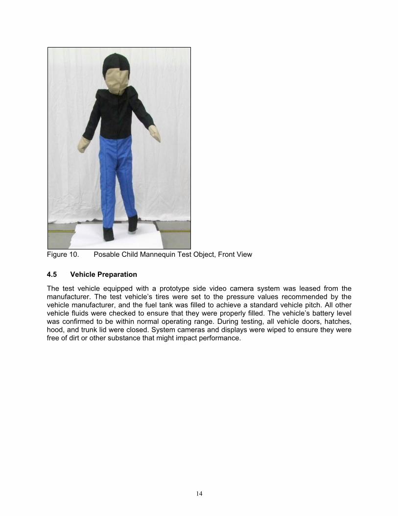
One of the test objects used in this program was a posable pedestrian child mannequin developed by 4a Engineering GmbH, Traboch, Austria. The mannequin is 46.5 inches (1.18 m) in height and was designed to simulate a 6-year-old child. This mannequin is used in EuroNCAP. The posable child mannequin test object is shown in the following figure.
14
Figure 10. Posable Child Mannequin Test Object, Front View
4.5 Vehicle Preparation
The test vehicle equipped with a prototype side video camera system was leased from the manufacturer. The test vehicle’s tires were set to the pressure values recommended by the vehicle manufacturer, and the fuel tank was filled to achieve a standard vehicle pitch. All other vehicle fluids were checked to ensure that they were properly filled. The vehicle’s battery level was confirmed to be within normal operating range. During testing, all vehicle doors, hatches, hood, and trunk lid were closed. System cameras and displays were wiped to ensure they were free of dirt or other substance that might impact performance.

15
5.0 RESULTS
This section summarizes the examination types performed for the prototype side CMS and corresponding observations. Assessments involving stationary laboratory and test track conditions are presented first, followed by on-road driving observations.
5.1 Field of View Measurement
Fields of view for both the side CMS and the original equipment traditional mirror system were measured. The indirect field of view of the prototype camera monitor system (as installed on a 2016 Audi A4) was measured based on the default system settings (i.e., no image zoom adjustment). Since the camera position for such a system is fixed, the field of view is the same for any size of driver and no particular eye point or seat position settings were required. To determine the side CMS default displayed field of view, the vehicle was positioned on a level test surface marked with a dimensioned 50-foot-wide and 50-foot-long grid of 1-foot squares. A visual target was moved about the grid and the locations at which the target was visible were manually noted. The visual target was a 26.4-inch-tall (67.1 cm) traffic cone with a 3-inch (7.62 cm) diameter red, circular reflector on top. For the CMS, the target was considered to be visible when the entire reflector could be seen in either of the side camera monitor system displays. The indirect field of view of the original equipment mirror system for the 2017 Audi A4 test vehicle was determined using an approximately 50th percentile male driver. The seat was positioned at the mid-point of seat track travel, mid-point of height, and with the seat back at approximately 25 degrees. The outside rearview mirrors were adjusted such that the sides of the vehicle (the door handles) were barely visible in the FOV with the male driver seated normally, to maximize the amount of view of the adjacent lane while still having the door handles in view for reference. The degree of pitch for both outside mirrors was adjusted such that the view was approximately centered on the horizon when the driver was seated normally. The same 26.4-inch-tall visual target as was used for CMS field of view measurement was moved throughout the grid and locations were noted at which the driver could see the entire reflector at the top of the target. The driver was permitted to move and turn his head, but tried to minimize body movement within the confines of the seat belt as positioned for normal upright seated body posture for driving. Figure 11 below shows the fields of view for the prototype side CMS and the original equipment mirror system (2017 Audi A4), respectively. Both figures show the test vehicle with its rear bumper face centered at the (0,0) location on the grid. The outside mirror and side camera locations are indicated with small triangles on both sides of the vehicle, which is represented by a rectangular outline. The driver’s eye point location is also indicated using a small black circle within the vehicle’s perimeter. Grid locations around the vehicle at which the visual target was visible via the mirror or camera system are indicated in both figures using gray circles. A horizontal green line is used to highlight the FMVSS No. 111 outside rearview mirror field of view requirement (S5.2) which states, “The mirror shall provide the driver a view of a level road surface extending to the horizon from a line, perpendicular to a longitudinal plane tangent to the driver's side of the vehicle at the widest point, extending 2.4 m out from the tangent plane 10.7 m behind the driver's eyes, with the seat in the rearmost position.” The resultant area is indicated by an outlined triangular area on both sides of the vehicle.

16
Figure 11. Fields of View for Prototype Side Rearview CMS and Original Equipment Mirrors

17
As can be seen in the field-of-view depiction in Figure 11, the CMS visible area encompasses the FMVSS No. 111 required area. The CMS field of view covers an area extending outward from the sides of the car that is somewhat wider than that of the original equipment outside rearview mirrors. The CMS also displays more of the area directly behind the vehicle.
The direct vision field-of-view for the 2017 Audi A4 test vehicle is illustrated in Figure 12 below. This direct field of view was determined using the method outlined in the NHTSA report, Direct Rear Visibility of Passenger Cars: Laser-Based Measurement Development and Findings for Late Model Vehicles [4].
Figure 12. Direct Vision Field-of-View for the 2017 Audi A4 Test Vehicle

18
5.2 Visibility of Test Objects in Daytime and Nighttime Conditions
Testing was conducted in which the visibility of specific test objects was assessed in a stationary setting. Two test objects were used to assess the side camera monitor system’s ability to clearly present objects in the field of view, at various distances behind the vehicle in an adjacent lane position. One object was a sedan, while the other was a posable pedestrian child mannequin developed by 4a Engineering GmbH of Traboch, Austria. For comparison, the vehicle with traditional outside mirrors was also used in this examination. The outside mirrors were adjusted such that a 50th percentile male driver could just see the edge of the vehicle’s side, like that seen with the side camera monitor system.
The following table provides an outline of the conditions assessed and documented by taking photographs.
Table 1. Outline of Tests of Objects in Field of View, Adjacent Lane Scenarios
Conditions Variations
2 Light Conditions Day and night
2 Test Objects Sedan and posable child mannequin
2 Lateral Test Object Locations Left and right, 6 feet (1.8 m) laterally from side of test vehicle
• To side of sedan test object • To longitudinal center of child mannequin
7 Longitudinal Test Object Locations
3 locations aft of test vehicle front bumper: 5, 10 and 15 feet (1.52, 3.05 and 4.57 meters) 4 locations aft of test vehicle rear bumper: 5, 16.4, 32.8 and 82.0 feet (1.52, 5, 10 and 25 meters)
Figure 12 below illustrates how the CMS test vehicle and child mannequin were positioned for the 7 longitudinal test locations. Figure 13 depicts the CMS test vehicle and sedan as tested for the 100 feet aft of front bumper test location.

19
Figure 13. Illustration of Child Mannequin Test Object Positions With Respect to the CMS Test Vehicle Location.

20
Figure 14. Illustration of Sedan Test Object Positioned 10 Feet Aft of CMS Test Vehicle Front Bumper.

21
Table 2 provides a summary of whether the test objects were visible for each of the scenario combinations listed in the table above. Test objects were visible with the CMS but not with mirrors in 2 daytime trials and 9 nighttime trials.
Table 2. Test Object Visibility by Location and System (CMS Versus Mirrors)
Test Object Position Sedan Posable Child Mannequin
Day/Night
Longitudinal Location With Respect to Test
Vehicle Bumper
Driver/ Passenger
Side CMS Mirrors CMS Mirrors
Day
5 ft (1.52 m) aft of front Driver Visible No No No
Passenger Visible No No No
10 ft (3.05 m) aft of front Driver Visible No No No
Passenger Visible Visible No No
15 ft (4.57 m) aft of front Driver Visible No No No
Passenger Visible Visible No No
5 ft (1.52 m) aft of rear Driver Visible Visible Visible No
Passenger Visible Visible Visible Visible
16.4 ft (5 m) aft of rear Driver Visible Visible Visible Visible
Passenger Visible Visible Visible Visible
32.8 ft (10 m) aft of rear Driver Visible Visible Visible Visible
Passenger Visible Visible Visible Visible
82 ft (25 m) aft of rear Driver Visible Visible Visible Visible
Passenger Visible Visible Visible Visible
Night
5 ft (1.52 m) aft of front Driver Visible No No No
Passenger Visible No No No
10 ft (3.05 m) aft of front Driver Visible No No No
Passenger Visible Visible No No
15 ft (4.57 m) aft of front Driver Visible No No No
Passenger Visible Visible No No
5 ft (1.52 m) aft of rear Driver Visible Visible Visible No
Passenger Visible Visible Visible No
16.4 ft (5 m) aft of rear Driver Visible Visible Visible No
Passenger Visible Visible Visible No
32.8 ft (10 m) aft of rear Driver Visible Visible Visible No
Passenger Visible Visible No No
82 ft (25 m) aft of rear Driver Visible Visible No No
Passenger Visible Visible No No

22
With its wider field of view, the CMS is able to display both test objects at locations next to the vehicle (the aft of front bumper locations) that cannot be seen with traditional mirrors. Figure 15 illustrates this observation for the sedan test object positioned 15 feet aft of the test vehicles’ front bumpers.
Figure 15. Sedan Positioned 15 Feet (4.57 m) Aft of Front Bumper, as Viewed With Side CMS (top) and Mirrors (bottom) on Driver (left) and Passenger Side (right)
The CMS wider field of view presented over a similar area as a traditional mirror surface results in an image having minification resulting in the child mannequin appearing thinner at a distance of 82 feet aft of the vehicle’s rear bumper, as can be seen in Figure 16.
23
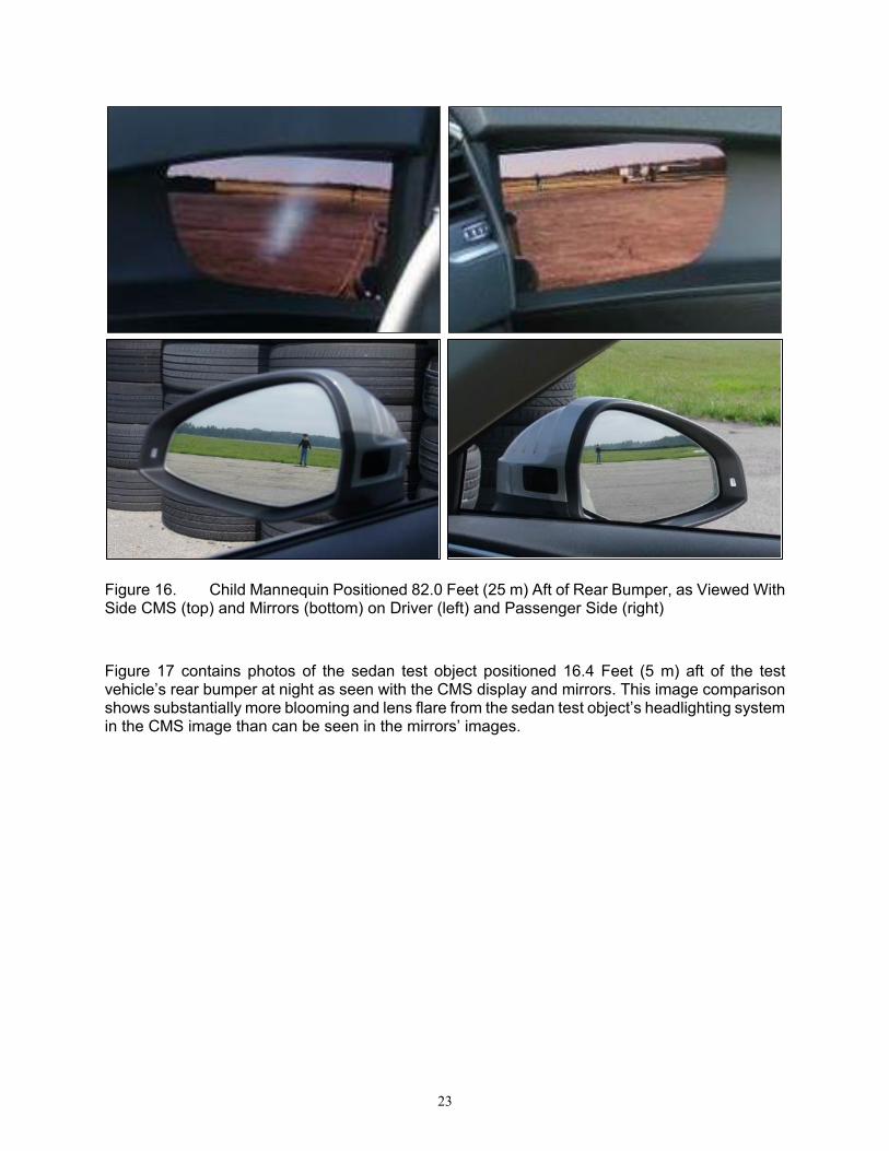
Figure 16. Child Mannequin Positioned 82.0 Feet (25 m) Aft of Rear Bumper, as Viewed With Side CMS (top) and Mirrors (bottom) on Driver (left) and Passenger Side (right)
Figure 17 contains photos of the sedan test object positioned 16.4 Feet (5 m) aft of the test vehicle’s rear bumper at night as seen with the CMS display and mirrors. This image comparison shows substantially more blooming and lens flare from the sedan test object’s headlighting system in the CMS image than can be seen in the mirrors’ images.
24
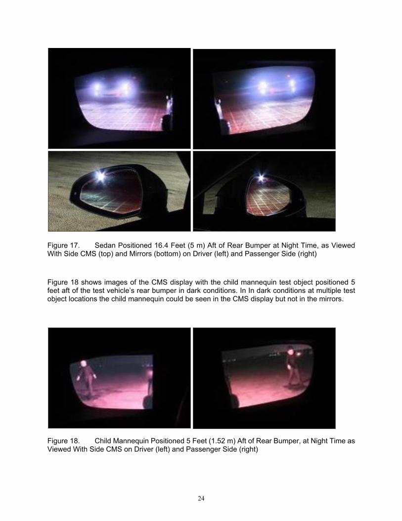
Figure 17. Sedan Positioned 16.4 Feet (5 m) Aft of Rear Bumper at Night Time, as Viewed With Side CMS (top) and Mirrors (bottom) on Driver (left) and Passenger Side (right)
Figure 18 shows images of the CMS display with the child mannequin test object positioned 5 feet aft of the test vehicle’s rear bumper in dark conditions. In In dark conditions at multiple test object locations the child mannequin could be seen in the CMS display but not in the mirrors.
Figure 18. Child Mannequin Positioned 5 Feet (1.52 m) Aft of Rear Bumper, at Night Time as Viewed With Side CMS on Driver (left) and Passenger Side (right)
25
A complete set of figures showing side-by-side photos of CMS display images and mirror images with the objects placed at each of the described locations for comparison is included in Appendix Section 9.2.
5.2.1 Cases of Daytime CMS Display Glare
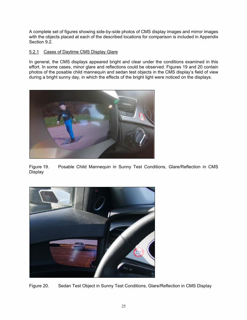
In general, the CMS displays appeared bright and clear under the conditions examined in this effort. In some cases, minor glare and reflections could be observed. Figures 19 and 20 contain photos of the posable child mannequin and sedan test objects in the CMS display’s field of view during a bright sunny day, in which the effects of the bright light were noticed on the displays.
Figure 19. Posable Child Mannequin in Sunny Test Conditions, Glare/Reflection in CMS Display
Figure 20. Sedan Test Object in Sunny Test Conditions, Glare/Reflection in CMS Display
26
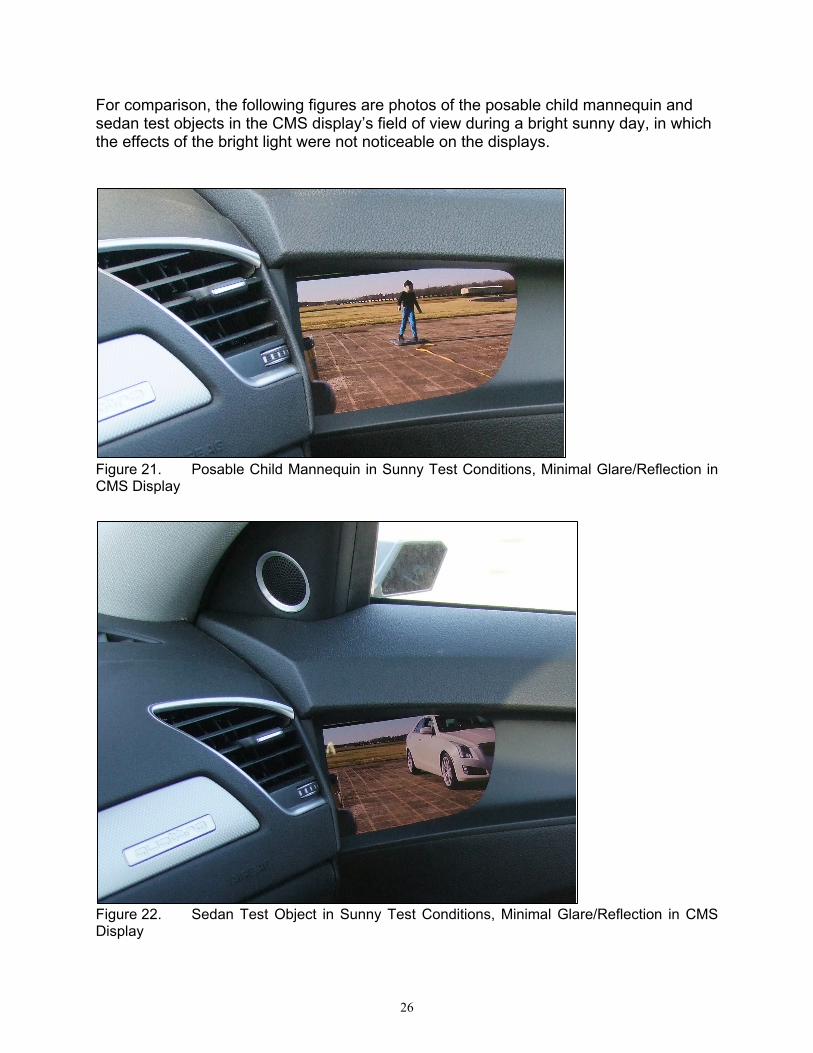
For comparison, the following figures are photos of the posable child mannequin and sedan test objects in the CMS display’s field of view during a bright sunny day, in which the effects of the bright light were not noticeable on the displays.
Figure 21. Posable Child Mannequin in Sunny Test Conditions, Minimal Glare/Reflection in CMS Display
Figure 22. Sedan Test Object in Sunny Test Conditions, Minimal Glare/Reflection in CMS Display

27
5.3 Image Quality Examination
In the ISO 16505 test procedures, a chessboard chart is used to help quantify factors involving image quality and magnification. Although the objectives of this work did not involve executing such objective test procedures, a chessboard chart was utilized in the capturing of output images from each of the side-view cameras in the prototype system. Photos were taken of the side CMS displays in a controlled test bay under both light and dark conditions. For dark conditions, the laboratory bay lights were off and photos were taken in conditions in which the vehicle’s taillights were on and conditions in which the vehicle’s taillights were off. The laboratory bay lights were all on for the photos taken under lighted conditions.
All photos were taken by a camera in which the camera charge-coupled device (CCD) was 26.75 inches (67.9 cm) from the center of the driver’s side CMS display. The camera was positioned at a downward angle of 20.9 degrees for the driver’s side photos and at a downward angle of 11.0 degrees for the passenger’s side photos.
For this evaluation, the chessboard chart was centered 66 inches (1.68 m) to the left of the vehicle’s centerline for placement in the field of view of the driver’s side-view camera (and centered 66 inches (1.68 m) to the right for the passenger-side camera), at distances of 120 inches (near photo, 3.05 m) and 180 inches (far photo, 4.57 m) longitudinally behind the camera’s glass cover. The dimensions of the chessboard chart were 39.37 inches (100 centimeters) in width and 31.50 inches (80 centimeters) in height, consisting of 20 squares wide and 16 squares tall. Thus, each square was 1.97 inches (5 centimeters) in width and height. The bottom of the chessboard chart was 7.40 inches (18.8 centimeters) above the ground and level.
The following figures are examples of the chessboard chart in the field of view of the side-view cameras. As can be seen in the figures, segments of a tape measure were placed over the image surface to provide dimensions of the chessboard chart as it appeared in the displays. The chessboard image in both display types was generally clear.

28
Figure 23. Near and Far Chessboard in Lighted Environment as Viewed With Driver (left) and Passenger Side (right) CMS Displays

29
Figure 24. Driver (left) and Passenger Side (right) CMS Displays Showing Near (top) and Far (bottom) Chessboard, Dark Environment, Vehicle Tail Lights On
Figure 25. Near Chessboard in Dark Environment With Vehicle Tail Lights Off as Viewed With Driver (left) and Passenger Side (right) CMS Displays
For comparison, the following figures are examples of the chessboard chart in the field of view of the test vehicle with standard outside rearview mirrors.

30
Figure 26. Near and Far Chessboard in Lighted Environment as Viewed With Driver (left) and Passenger Side (right) Mirrors
Figure 27. Near and Far Chessboard in Dark Environment as Viewed With Driver (left) and Passenger Side (right) Mirrors
31
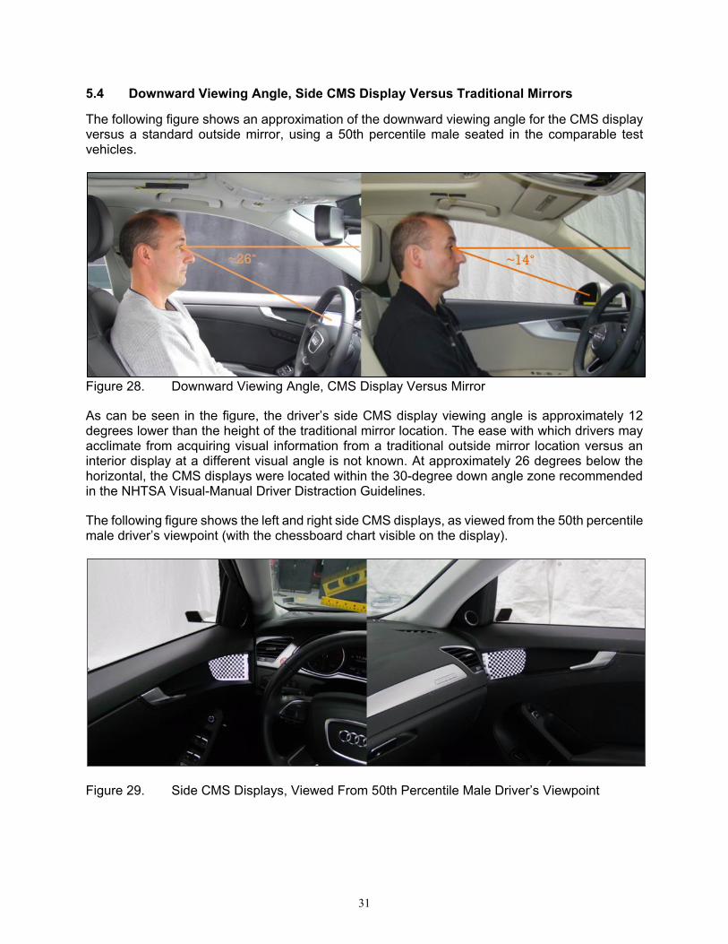
5.4 Downward Viewing Angle, Side CMS Display Versus Traditional Mirrors
The following figure shows an approximation of the downward viewing angle for the CMS display versus a standard outside mirror, using a 50th percentile male seated in the comparable test vehicles.
Figure 28. Downward Viewing Angle, CMS Display Versus Mirror
As can be seen in the figure, the driver’s side CMS display viewing angle is approximately 12 degrees lower than the height of the traditional mirror location. The ease with which drivers may acclimate from acquiring visual information from a traditional outside mirror location versus an interior display at a different visual angle is not known. At approximately 26 degrees below the horizontal, the CMS displays were located within the 30-degree down angle zone recommended in the NHTSA Visual-Manual Driver Distraction Guidelines.
The following figure shows the left and right side CMS displays, as viewed from the 50th percentile male driver’s viewpoint (with the chessboard chart visible on the display).
Figure 29. Side CMS Displays, Viewed From 50th Percentile Male Driver’s Viewpoint

32
5.5 CMS Display Brightness in Dark Driving Conditions
The prototype side CMS display system had daytime and nighttime modes that were manually selectable via touch controls on the driver-side CMS display. The default mode, daytime, was used throughout this effort as it was assumed initially that the displays’ brightness levels were adjusted automatically.
Upon examining both daytime and nighttime modes in dark conditions, it was determined there was not much subjectively observable difference between the two conditions. Both modes appeared similarly bright. In dark driving conditions, the brightness of the prototype CMS displays (in the default setting) was great enough that it caused a degree of discomfort glare for those driving the vehicle.
ISO 16505 contains display brightness requirements, as stated below:
“ISO 16505 6.10.1.2 Glare due to high luminance of the monitor
In order to avoid glare due to high luminance of the monitor the luminance shall be dimmable under night condition either manually or automatically. The maximum luminance under night condition should not exceed 20 cd/m2.”
While equipment for measuring display luminance was not available, an illuminance meter was available that could be used to measure the amount of light that would reach the driver’s eyes. CMS display illuminance (in the default setting) was measured at the eye midpoint location of a 50th percentile male driver under dark conditions, with and without a stationary following vehicle in the same or adjacent lane. These measurements were made for both the side CMS equipped vehicle and the mirrored vehicle for comparison. Both the CMS vehicle and other vehicle were centered in their respective lanes and had lower beam headlamps powered on.
To isolate the light emitted by the CMS displays, the dashboard in the vehicle for which illuminance was being measured was covered with blankets in all trials except one. The final test trial for each vehicle measured illuminance with the dashboard uncovered to quantify the illuminance produced by instrument panel and center stack displays. Ambient illumination measurements were also obtained in which there were no other vehicle lights present and the test vehicle was off.
All illuminance measurements were adjusted during data processing to account for the ‘ambient conditions’ of each vehicle, by subtracting the illuminance value obtained during the first trial from the values obtained from each of the other trials for that vehicle.
The following table describes each of the conditions in which interior illuminance data were obtained and the corresponding adjusted illuminance values. The subsequent figure illustrates the measured illuminance values.

33
Table 4. Measurements for Illuminance at the Driver’s Eye Midpoint for CMS Displays Versus Mirrors
Trial Condition (dashboard covered unless
otherwise indicated)
Vehicle Engine
On or Off Other Vehicle
Location Illuminance (lux)
CMS Mirrors
Ambient (no headlamps or interior lights) Off None 0 0
Vehicle Only On None 0.48 0.12
Same Lane, 16.4 ft (5 m) Aft On 5 m behind 0.52 0.19
Same Lane, 32.8 ft (10 m) Aft On 10 m behind 1.02 0.40
Same Lane, 82.0 ft (25 m) Aft On 25 m behind 0.98 0.25
Adjacent Left Lane, 16.4 ft (5 m) Aft On 5 m behind in left adjacent lane 0.59 0.49
Adjacent Left Lane, 32.8 ft (10 m) Aft On 10 m behind in left adjacent lane 0.64 0.58
Adjacent Left Lane, 82.0 ft (25 m) Aft On 25 m behind in left adjacent lane 0.76 0.14
Dashboard Not Covered On None 0.61 0.48
Figure 30. Measured Illuminance, CMS Displays Versus Mirrors

34
Measured illuminance values were lower than the test staff anticipated they would be based on direct, subjective observation of the displays in nighttime conditions. While measured illuminance values did not approach a level that would be considered truly glaring to the driver, the constant unnecessary illumination coming from the CMS displays even when no other vehicle was nearby could be distracting or annoying to drivers in dark conditions, particularly in areas without street lights or other environmental lighting.
5.6 Observations Based on Driving the CMS-Equipped Vehicle on Public Roads
The CMS-equipped test vehicle was driven on public roads under various conditions to assess system performance and any driver acclimation issues. In general, the conditions included both day and night time driving, under dry and wet conditions, including rain. The following sections describe observations made under combinations of those conditions.
5.6.1 Observations Based on Daytime Driving on Public Roads by Test Staff
In general, the side CMS displays worked well during normal daytime conditions. The display screens provided good image clarity, even under sunny conditions. Several lane changes were performed during highway driving, in which the CMS with its wide field of view worked well in assisting the driver in performing such a maneuver safely with a high degree of confidence. Once the driver got acclimated to looking at the CMS display location instead of outside the window at a mirror, the system was relatively easy to use. The location of the CMS display, being inside the vehicle and at an additional downward angle compared to outside mirrors, did require some learning and effort initially. Generally, the CMS display was not much different than using a mirror, except that the CMS provided a somewhat broader field of view and the driver did not have to move his or her head around to see more.
5.6.2 Observations Based on Daytime Driving on Public Roads by a Naïve Driver
For an additional assessment, a naïve driver who previously had no exposure to a side CMS was asked to take the CMS-equipped vehicle for a test drive under dry daytime conditions. The naïve driver began by backing the vehicle out of a garage bay and then proceeded out of a parking lot and along the rural access road of the test facility to exit the facility and drive on public roads. The total drive length was approximately 40 miles, with moderate other traffic present the whole time. Most of the drive consisted of approximately 30 miles of driving on a divided highway, consisting of two lanes in each direction, in which the driver used the CMS to make lane changes. The driver also experienced approximately 5 miles of rural road driving and approximately 5 miles of city driving during the trip, to provide a diversity of natural scenarios in which to experience the CMS capabilities. The following describes the naïve driver’s initial reactions to the side CMS displays:
• Initially noticed there were no side mirrors upon making attempts to adjust the seat and mirrors to her comfort level.
• Spent some time sitting stationary, getting familiar with the visual displays. • Used a combination of center backing display, side-view displays and looks over the
shoulder to back out of garage.

35
The following is a list of the naïve driver’s post-drive comments pertaining to the side camera monitor system:
• I had to adjust to how low they were and the viewing angle. I kept looking to where they are on my car and was surprised when there was just a camera there and I had to look lower. Over the drive, I started to get used to looking lower.
• At first, it was disorienting looking between the road and the camera visual display. • I liked using the distance lines toward the end of the drive. They helped me determine
when it was safe to change lanes by using the different line colors. • I also liked that it seemed like I could see farther back in the mirrors than I normally would
from outside rearview mirrors. I could see a lot more of the road than I was expecting. • The image quality was pretty good. I could see a car coming up behind me in the lane next
to me from pretty far back. • I never really stopped checking my blind spot when changing lanes for this drive even
though I didn’t really need to with these side cameras. • I think it would be very useful at night to eliminate glare from other vehicles’ headlights. • Overall, I did have to get used to the wider field of view the cameras provided. Looking
between the road and the side camera view was disorienting at first but I got acclimated to it over the drive. I really liked how much of the road I could see, as well as the clarity of the video. I also liked the distance line feature, especially when changing lanes.
5.6.3 Observations Based on Driving on Public Roads at Dusk
At dusk, the displayed image appeared brighter than the actual conditions. As can be seen in the following figure, the conditions appear mostly dark when looking forward through the windshield (top left portion of photo), but the CMS display image appears much brighter, like what may be seen in daytime conditions.
Figure 31. Photo of Passenger-Side CMS Display and Portion of Forward Windshield View, Highlighting the Disparity in Apparent Ambient Illumination at Dusk
36
5.6.4 Observations for Driving on Public Roads at Nighttime
The following subsections depict some of the conditions experienced when using the side CMS at night.
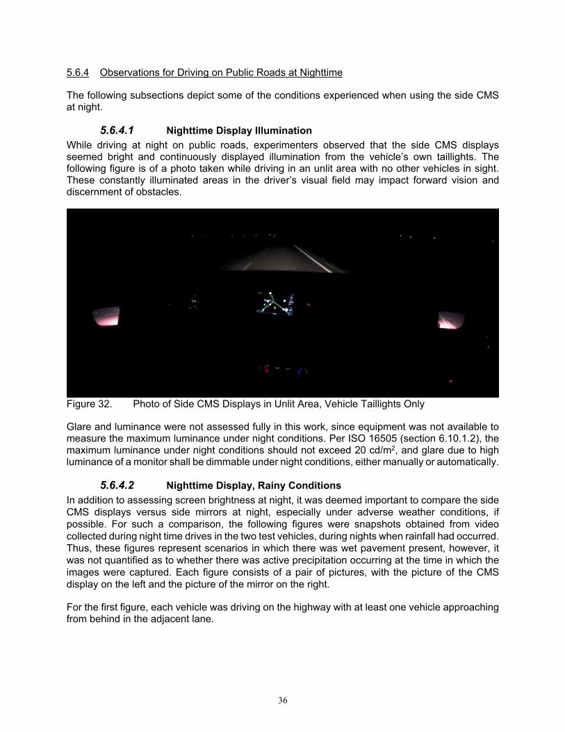
5.6.4.1 Nighttime Display Illumination While driving at night on public roads, experimenters observed that the side CMS displays seemed bright and continuously displayed illumination from the vehicle’s own taillights. The following figure is of a photo taken while driving in an unlit area with no other vehicles in sight. These constantly illuminated areas in the driver’s visual field may impact forward vision and discernment of obstacles.
Figure 32. Photo of Side CMS Displays in Unlit Area, Vehicle Taillights Only
Glare and luminance were not assessed fully in this work, since equipment was not available to measure the maximum luminance under night conditions. Per ISO 16505 (section 6.10.1.2), the maximum luminance under night conditions should not exceed 20 cd/m2, and glare due to high luminance of a monitor shall be dimmable under night conditions, either manually or automatically.
5.6.4.2 Nighttime Display, Rainy Conditions In addition to assessing screen brightness at night, it was deemed important to compare the side CMS displays versus side mirrors at night, especially under adverse weather conditions, if possible. For such a comparison, the following figures were snapshots obtained from video collected during night time drives in the two test vehicles, during nights when rainfall had occurred. Thus, these figures represent scenarios in which there was wet pavement present, however, it was not quantified as to whether there was active precipitation occurring at the time in which the images were captured. Each figure consists of a pair of pictures, with the picture of the CMS display on the left and the picture of the mirror on the right.
For the first figure, each vehicle was driving on the highway with at least one vehicle approaching from behind in the adjacent lane.

37
Figure 33. CMS Display Versus Mirror, Vehicle Behind in Adjacent Lane
For the next figure, each vehicle was driving on the highway with multiple vehicles approaching from behind in the adjacent lane.
Figure 34. CMS Display Versus Mirror, Multiple Vehicles Behind in Adjacent Lane
The next figure just shows examples of vehicle tail lights from traffic driving in the other direction. As can be seen in this figure, the CMS display shows much more detail than the mirror, in which the entire vehicle across the median can be identified.
Figure 35. CMS Display Versus Mirror, Taillights of Other Traffic

38
The following figure is a photo taken of the passenger side CMS display while driving on the highway at night under wet conditions with vehicles behind the test vehicle. The photo depicts water droplets present on the camera lens cover. Water droplets were observed to remain on the lens cover for a prolonged period, causing substantial distortion of the side view as can be seen in the figure. This distortion, at times, rendered the side image generally unusable to the driver for determining what objects may be present in the adjacent lane.
Figure 36. Photo of Passenger-Side CMS Display in Rainy Conditions
5.6.4.3 Nighttime Driving, Blooming, Lens Flare Both European standards (ISO and ECE) list criteria and test procedures for assessing blooming and lens flare. The ISO standard (ISO 16505 section 6.7.4.2) states:
“Blooming and lens flare cause partial occlusion of the field of view and of the objects. Blooming and lens flare artefacts shall not cover more than 25 % of the displayed image (see test method 4.1 in 7.8.2).”
The ECE standard (R46 section 6.2.2.3.3.5.2) states:
“The total area of disturbing blooming and lens flare areas shall not cover more than 25 percent of the displayed camera image.”
Although equipment was not available to perform the actual test procedures described in the standards, blooming and lens flare were observed during night time driving on public roads. The following figure is a snapshot from a video clip taken when a vehicle was passing the test vehicle on the left side, in which the vehicle headlights were not distinguishable from one another, with apparent blooming and lens flare covering a large area (greater than 25 percent) of the driver side CMS display image.

39
Figure 37. Driver-Side CMS Display, Blooming and Lens Flare
The following figure, another example of blooming, is a snapshot taken from on-road video data recorded during nighttime highway driving where the system-equipped vehicle is being passed on the left side.
Figure 38. Image of Vehicle Headlights Passing on the Left at Night With Blooming Visible in CMS Display
40
6.0 SUMMARY OF OBSERVATIONS AND ADDITIONAL DISCUSSION
6.1 Summary of Observations
Several positive qualitative observations were made in the context of the current effort to assess a prototype side camera monitor system. These include:
– Image clarity seems good in dry conditions. – In dawn and dusk conditions, displayed images appeared brighter (helpful) than would
be seen with traditional mirrors. – Prototype CMS field of view covered the FMVSS No. 111 required area. – Only minor instances of sunlight reflections were witnessed on the displays. – At approximately 26 degrees below the horizontal, the CMS displays were located
within the 30-degree down angle zone recommended in the NHTSA Visual-Manual Driver Distraction Guidelines. However, it is unknown how easily drivers may acclimate to using electronic displays in this new location for visibility.
The following is a list of observations of potential issues (for which more information is needed for a better assessment) made during these evaluations:
– “High” display illuminance in dark driving conditions may negatively impact drivers’ ability to discern forward obstacles.
The following is a list of observations considered to be areas for improvement for this particular prototype that should be remedied:
– Image obscuration can occur in rainy conditions due to water droplets on the camera lens.
– Substantial blooming of other vehicle headlights was experienced during dark (night driving) conditions.
6.2 Additional Issue That May Impact Side CMS Usability: Display Viewing Problems With Polarized Eyeglass/Sunglass Lenses
This examination of side camera monitor system performance was necessarily brief due to limited duration access to a prototype system. A comprehensive assessment of the performance of such a system would address several other performance aspects and factors with a focus on safety. One issue that was not addressed in the context of this brief examination involves display viewing problems that may be encountered by drivers wearing polarized sunglasses. Polarized lenses are designed to help block glare and haze caused by reflected light (from water and solid surfaces). Polarized lenses help the user see objects more clearly by basically blocking the horizontal light waves, which increases contrast to sharpen the user’s view. However, since in-vehicle displays (such as LCDs) often also use polarizing filters to combat reflected light, displays may tend to appear dark when seen through polarized lenses. Re-orienting the light waves for one ‘device’ can help but not entirely solve such issues when multiple ‘devices’ are performing the same filtering of light before reaching the human eye. Side CMS must consider this issue in the design of the display to ensure that drivers will still be able to effectively see objects in the video image and maintain situational awareness if wearing polarized sunglasses.
41
7.0 SUMMARY
This report describes the examination of a prototype side camera monitor system as a potential replacement for outside mirrors. This effort provides information to support NHTSA’s decisions regarding whether to take actions to revise FMVSS No. 111 to permit such technologies. A prototype system was obtained and a brief examination was conducted. Measurements and observations were made with the vehicle stationary in both laboratory and test track settings. Public road driving in daytime and nighttime dry and rainy conditions was also performed with multiple members of the research staff as drivers. Relevant standards were reviewed from the ISO and the draft ECE standards to assess their usefulness as a basis for establishing an FMVSS-suitable performance standard. The prototype CMS exceeded the rear visibility field of view requirements of FMVSS No. 111, as is the case with most installed outside rearview mirrors on vehicles sold in the United States. However, the wider field of view presented in a surface area like that of a standard outside rearview mirror caused minification of objects rendering them narrower and more difficult to discern. While display glare caused by sunlight was a foreseen issue, only minimal such glare was observed. CMS image clarity was good, comparable to that of outside rearview mirrors. Visibility was especially good during dusk and dawn conditions when the displayed areas appeared brighter than would be seen with traditional mirrors. One major unknown with this new technology is how well drivers may acclimate to the new display type and typically lower, interior mounting location for the electronic displays. The prototype CMS examined in this testing presented its side rearview image via a visual display located at the upper forward corner of the front door. The associated visual angle for a driver looking at this display would be approximately 12 degrees lower than for a traditional outside rearview mirror location, which may be somewhat disorienting for drivers at least for some initial period of time. Another potential issue was perceived “high” display illuminance witnessed during conditions in which researchers were driving at night. Aspects of the prototype system’s performance that may be cause for concern included excessive blooming and lens flare from headlights of other traffic at night that exceeded that permitted in the related ISO standard. Other issues included image obscuration due to water droplets remaining on the camera lens while driving and high display brightness that in dark driving conditions may glare and annoy drivers, as well as make discerning of forward objects more difficult. It is currently unclear whether these issues may be adequately remedied in a cost-effective manner.
Other unknowns regarding this new technology include the questions of whether system reliability, image availability, and image quality across the range of conceivable driving conditions would be sufficient to match the performance of traditional mirrors and therefore maintain at least a status quo in terms of safety level and situational awareness drivers have come to expect. Factors such as blooming, glare, and water on the lens cover may combine to result in a substantial portion of time when a usable image is not available to the driver. Similarly, how drivers may react to a side CMS display image not being available in the event of a system malfunction is unknown.
42
Based on these observations, the following questions are posed for future designs: • Can night mode be improved to have lower display luminance? • Can image obscuration from water droplets be remedied? • Can following vehicle headlight blooming be reduced? • Is there an optimal downward viewing angle for such displays that maximizes drivers’
comfort and situational awareness?
NHTSA believes a driver's ability to clearly see the area around his or her vehicle is critical to safe driving and avoiding crashes. Over the past two decades, the agency has conducted several research studies that sought to examine specific aspects of electronic and mirror technologies designed to improve driver visibility around vehicles. NHTSA has considered pertinent issues and examined the literature for relevant safety issues and objective performance metrics that support electronic technologies for visibility. However, to fully evaluate the merits of the current petitions, additional information pertaining to technical aspects of testing the safety relevant performance of camera monitor systems, as well as human factors information on the requested systems, is needed. This review has identified several potential safety-relevant questions, human factors information gaps, and test procedures details that need to be answered before appropriate performance requirements could be proposed to ensure that camera-based systems provide at least the same level of safety to the public as today's side mirrors. These remaining questions include:
• Will drivers acclimate easily to electronic displays for side visibility? • Will display location (inside the vehicle) and visual angle difference from traditional mirror
location bother drivers enough to impact safety? • Will display brightness annoy and/or compromise forward vision?

43
8.0 REFERENCES
1. 49 CFR Sec. 571.111, Standard No. 111; Rear Visibility.
2. ECE R46, Uniform provisions concerning the approval of devices for indirect vision and of motor vehicles with regard to the installation of these devices.
3. ISO 16505:2015, Road Vehicles – Ergonomic and performance aspects of Camera Monitor Systems – Requirements and test procedures.
4. Mazzae, E. N., & Barickman, F. S. (2009). Direct rear visibility of passenger cars: laser-based measurement development and findings for late model vehicles (Report No. DOT HS 811 174). Washington, DC: National Highway Traffic Safety Administration. Available at https://one.nhtsa.gov/DOT/NHTSA/NRD/Multimedia/PDFs/Human%20Factors/Driver%20Assistance/811174.pdf

44
9.0 APPENDIX
9.1 Images of Test Vehicles
2016 Audi A4 With Side Video Displays
Figure 39. Audi A4, Front and Rear Views
Figure 40. Audi A4, Four Three-Quarter Views

45
2017 Audi A4 With Side Mirrors
Figure 41. Audi With Mirrors, Front and Rear Views
Figure 42. Audi With Mirrors, Four Three-Quarter Views

46
9.2 CMS Versus Mirror Image Comparison Photos
This section contains photographic data documenting test object visibility in various stationary positions with respect to the test vehicle. The outside mirrors were adjusted such that a 50th percentile male driver could just see the edge of the vehicle’s side, like that seen with the side camera monitor system. The pitch of the mirrors’ adjustment in the dark conditions photos is more downward than that in the daylight photos. Table 2 presented earlier in this report summarizes results for visibility (visible or not visible) for both test objects. These photos generally illustrate the somewhat wider field of view of the CMS as compared to the mirrors. In the CMS daytime photos, minification of the child mannequin test object is apparent in the photos.
9.2.1 Daylight Image Comparison Photos
This section contains daylight image photos for the sedan and child mannequin stationary test objects as viewed with the CMS and original equipment mirrors. The first group of photos shows the sedan test object placed at the various longitudinal test locations as specified in each figure’s caption.
Figure 43. Sedan Positioned 5 Feet (1.52 m) Aft of Front Bumper, as Viewed With Side CMS (top) and Mirrors (bottom) on Driver (left) and Passenger Side (right)

47
Figure 44. Sedan Positioned 10 Feet (3.05 m) Aft of Front Bumper, as Viewed With Side CMS (top) and Mirrors (bottom) on Driver (left) and Passenger Side (right)
Figure 45. Sedan Positioned 15 Feet (4.57 m) Aft of Front Bumper, as Viewed With Side CMS (top) and Mirrors (bottom) on Driver (left) and Passenger Side (right)

48
Figure 46. Sedan Positioned 5 Feet (1.52 m) Aft of Rear Bumper, as Viewed With Side CMS (top) and Mirrors (bottom) on Driver (left) and Passenger Side (right)
Figure 47. Sedan Positioned 16.4 Feet (5 m) Aft of Rear Bumper, as Viewed With Side CMS (top) and Mirrors (bottom) on Driver (left) and Passenger Side (right)

49
Figure 48. Sedan Positioned 32.8 Feet (10 m) Aft of Rear Bumper, as Viewed With Side CMS (top) and Mirrors (bottom) on Driver (left) and Passenger Side (right)
Figure 49. Sedan Positioned 82.0 Feet (25 m) Aft of Rear Bumper, as Viewed With Side CMS (top) and Mirrors (bottom) on Driver (left) and Passenger Side (right)

50
For the next group of photos, the posable child mannequin is the test object, placed at the various longitudinal test locations as specified in each figure’s caption. The child mannequin test object was not visible in any of the “aft of front bumper” positions and as such photos are not present.
Figure 50. Child Mannequin Positioned 5 Feet (1.52 m) Aft of Rear Bumper, as Viewed With Side CMS (left) and Mirrors (right) on Passenger Side

51
(No Photo)
Figure 51. Child Mannequin Positioned 16.4 Feet (5 m) Aft of Rear Bumper, as Viewed With Side CMS (top) and Mirrors (bottom) on Driver (left) and Passenger Side (right)
Figure 52. Child Mannequin Positioned 32.8 Feet (10 m) Aft of Rear Bumper, as Viewed With Side CMS (top) and Mirrors (bottom) on Driver (left) and Passenger Side (right)

52
Figure 53. Child Mannequin Positioned 82.0 Feet (25 m) Aft of Rear Bumper, as Viewed With Side CMS (top) and Mirrors (bottom) on Driver (left) and Passenger Side (right)
9.2.2 Nighttime Image Comparison Photos
This section contains nighttime image photos for the sedan and child mannequin stationary test objects. The outside rearview mirror pitch adjustment was inadvertently pitched downward for these photos to a greater degree than for the daytime photos. For this next group of photos, the sedan is the test object, placed at the various longitudinal test locations at night time, as specified in each figure’s caption. In some cases, a complete set of photos was not available. Note that these photos look best when viewed in the electronic file as opposed to in a printed copy.

53
(No Photo)
Figure 54. Sedan Positioned 5 Feet (1.52 m) Aft of Front Bumper at Night Time, as Viewed With Side CMS (left) and Mirrors (right) on Passenger Side
(No Photo)
Figure 55. Sedan Positioned 10 Feet (3.05 m) Aft of Front Bumper at Night Time, as Viewed With Side CMS (left) and Mirrors (right) on Passenger Side

54
Figure 56. Sedan Positioned15 Feet (4.57 m) Aft of Front Bumper at Night Time, as Viewed With Side CMS (top) and Mirrors (bottom) on Driver (left) and Passenger Side (right)
Figure 57. Sedan Positioned 5 Feet (1.52 m) Aft of Rear Bumper at Night Time, as Viewed With Side CMS (top) and Mirrors (bottom) on Driver (left) and Passenger Side (right)

55
Figure 58. Sedan Positioned 16.4 Feet (5 m) Aft of Rear Bumper at Night Time, as Viewed With Side CMS (top) and Mirrors (bottom) on Driver (left) and Passenger Side (right)
Figure 59. Sedan Positioned 32.8 Feet (10 m) Aft of Rear Bumper at Night Time, as Viewed With Side CMS (top) and Mirrors (bottom) on Driver (left) and Passenger Side (right)

56
Figure 60. Sedan Positioned 82.0 Feet (25 m) Aft of Rear Bumper at Night Time, as Viewed With Side CMS (top) and Mirrors (bottom) on Driver (left) and Passenger Side (right)
For this next group of photos, the posable child mannequin is the test object, placed at the various longitudinal test locations at night time, as specified in each figure’s caption. In the following figure, comparison photos of the standard mirror were not available.
Figure 61. Child Mannequin Positioned 5 Feet (1.52 m) Aft of Rear Bumper, at Night Time as Viewed With Side CMS on Driver (left) and Passenger Side (right)

57
Figure 62. Child Mannequin Positioned 16.4 Feet (5 m) Aft of Rear Bumper, at Night Time as Viewed With Side CMS (top) and Mirrors (bottom) on Driver (left) and Passenger Side (right)
In the following figure, comparison photos were only available for the driver side.
Figure 63. Child Mannequin Positioned 32.8 Feet (10 m) Aft of Rear Bumper, at Night Time as Viewed With Side CMS (left) and Mirror (right) on Driver Side
In the following figure, comparison photos of the standard mirror were not available.
Figure 64. Child Mannequin Positioned 82.0 Feet (25 m) Aft of Rear Bumper, at Night Time as Viewed With Side CMS on Driver (left) and Passenger Side (right)

DOT HS 812 582 October 2018
13640-102518-v3