example problem 1: - ivy tech -- faculty...
TRANSCRIPT

1. EXAMPLE PROBLEM
In this relatively simple structure, we have a weight supported by two cables, which run over pulleys (which we will assume are very low friction) and are attached to 100 lb. weights as shown in the diagram. The two cords each make an angle of 50o with the vertical. Determine the weight of the body.
(The effect of the pulleys is just to change the direction of the force, it may be considered to not effect the value of the tensions in the ropes.)
1. Draw a Free Body Diagram (FBD) of the structure or a portion of the structure. This Free Body Diagram should include a coordinate system and vectors representing all the external forces (which include support forces and load forces) acting on the structure. These forces should be labeled either with actual known values or symbols representing unknown forces. The second diagram 2 is the Free Body Diagram of point just above the weight where with all forces come together.
2. Resolve (break) forces not in x or y direction into their x and y components. Notice for Cable 1, and Cable 2, the vectors representing the tensions in the cables were acting at angles with respect to the x-axis, that is, they are not simply in the x or y direction. Thus the forces Cable 1, Cable 2, we must be replaced with their horizontal and vertical components. In the third diagram, the components of Cable 1 and Cable 2 are shown.
1

3. Apply the Equilibrium Conditions and solve for unknowns. In this step we will now apply the actual equilibrium equations. Since the problem is in two dimensions only (coplanar) we have the following two equilibrium conditions: The sum of the forces in the x direction, and the sum of the forces in the y direction must be zero. We now place our forces into these equations, remembering to put the correct sign with the force, that is if the force acts in the positive direction it is positive and if the force acts in the negative direction, it is negative in the equation.
or, -100 cos 40o + 100 cos 40o = 0 (Just as we would expect, the x-forces balance each other.)
or, 100 sin 40o + 100 sin 40o - weight of body = 0In this instance, it is very easy to solve for the weight of the body from the y-equation; and find:Weight of body = 128.56 lb.
2. EXAMPLE PROBLEM
In this relatively simple structure, we have a 500 lb. load supported by two cables, which in turn are attached to walls. Let's say that we would like to determine the forces (tensions) in each cable.
If we examine Diagram-1 for a moment we observe this problem may be classified as a problem involving Concurrent, Coplanar Forces. That is, the vectors representing the two support forces in Cable 1 and Cable 2, and the vector representing the load force will all intersect at one point (Point C, See Diagram 2). When the force vectors all intersect at one point, the forces are said to be Concurrent. Additionally, we note that this is a two-dimensional problem, that forces lie in the x-y plane only. When the problem involves forces in two dimensions only, the forces are said to be Coplanar.
(Notice in this problem, that since the two supporting members are cables, and cables can only be in tension, the directions the support forces act are easy to determine. In later problems this will not necessarily be the case, and will be discussed later.)
2

To "Solve" this problem, that is to determine the forces (tensions) in cable 1 and cable 2, we will now follow a very specific procedure or technique, as follows:
1. Draw a Free Body Diagram (FBD) of the structure or a portion of the structure. This Free Body Diagram should include a coordinate system and vectors representing all the external forces (which include support forces and load forces) acting on the structure. These forces should be labeled either with actual known values or symbols representing unknown forces. Diagram 2 is the Free Body Diagram of point C with all forces acting on point C shown and labeled.
2. Resolve (break) forces not in x or y direction into their x and y components. Notice that T1, and T2, the vectors representing the tensions in the cables are acting at angles with respect to the x-axis, that is, they are not simply in the x or y direction. Thus for the forces T1, T2, we must replace them with their horizontal and vertical components. In Diagram 3, the components of T1 and T2 are shown.
Since the components of T1 and T2 (T1 sin 53o, T1 cos 53o, T2 sin 30o, T2 cos 30o) are equivalent to T1 and T2, in the final diagram 1d, we remove T1 and T2 which are now represented by their components. Notice that we do not have to do this for the load force of 500 lb., since it is already acting in the y-direction only.
3

3. Apply the Equilibrium Conditions and solve for unknowns. In this step we will now apply the actual equilibrium equations. Since the problem is in two dimensions only (coplanar) we have the following two equilibrium conditions: The sum of the forces in the x direction, and the sum of the forces in the y direction must be zero. We now place our forces into these equations, remembering to put the correct sign with the force, that is if the force acts in the positive direction it is positive and if the force acts in the negative direction, it is negative in the equation.
or, T1 cos53o - T2 cos30o = 0
or, T1 sin53o + T2 sin30o - 500 lb= 0Notice we have two equations and two unknowns (T1 and T2), and therefore can solve for the unknowns. There are several ways to solve these two 'simultaneous' equations. We could solve the first equation for T1 in terms of T2, (T1 = T2 cos 30o/cos 53o), and substitute the expression for T1 into the second equation [(T2 cos30o/cos53o)sin53o + T2 sin30o - 500 lb= 0], giving us only one equation and one unknown.
On solving the equations for T1 and T2 we obtain: T1 = 436 lb.; T2 = 302 lb. Thus, if the structure is to be in equilibrium, if the cables, acting at the angles given, are to support the 500 lb. load, then the forces in the cable must be as found above, 436 lb. and 302 lb., respectively. So when we go to purchase cables for our structure, we must be sure they will support loads at least equal to the tensions we found.
3. PRACTICE PROBLEMS
Draw a free body diagram and a force diagram as a part of the solution for each problem. All problems are coplanar with concurrent forces.
3a. Calculate the force in cable AB and the angle q for the support system shown. (447.2 lb. 63.4o)
3b. Calculate the horizontal force F that should be applied to the 200lb weight shown in order that the cable AB be inclined at an angle of 30° with the vertical. (115 lb.)
4

3c. Calculate the force in each cable for the suspended weight shown. (439 lb., 538 lb.)
4c. Two forces of 100 lb. each act on a body at an angle of 120o with each other. What is the weight of the body the two forces are supporting? (100 lb.)
5

5c. A wire 24 inches long will stand a straight pull of 100 lb. The ends are fastened to two points 21 inches apart on the same level. What weight suspended from the middle of the wire will break it? (96.8 lb.)
EXAMPLE PROBLEM 4:
In this first example, we will proceed very carefully and methodically. It is important to get the method and concepts we need to keep in mind firmly established.
In this problem we wish to determine all the external support forces (reactions) acting on the structure shown in Diagram 1 below. Once again our procedure consists basically of three steps.
1. Draw a Free Body Diagram of the entire structure showing and labeling all external load forces and support forces, include any needed dimensions and angles.
6

2. Resolve (break) all forces into their x and y-components.
3. Apply the Equilibrium Equations ( ) and solve for the unknown forces.
Step 1: Free Body Diagram (FBD). Making the FBD is probably the most important part of the problem. A correct FBD usually leads to a quick solution, while an inaccurate FBD can leave a student investing frustrating unsuccessful hours on a problem. With this in mind we will discuss in near excruciating detail the process of making a good FBD.
We note that the structure is composed of members ABC, and CD. These two members are pinned together at point C, and are pinned to the wall at points A and D. Loads of 4000 lb. and 2000 lb. are applied to member ABC as shown in Diagram 1.
In our example, the load forces are already shown by the downward arrows. We next look at the forces exerted on the structure by the supports. Since each support is a pinned joint, the worst case we could have is an unknown x and y-force acting on the structure at each support point. We also must choose directions for the x and y support forces. In some problems the directions of the support forces are clear from the nature of the problem. In other problems the directions the support forces act is not clear at all. However, this is not really a problem. We simple make our best guess for the directions of the support reactions. If our guess is wrong, when we solve for the value of the support forces, that value will be negative. This is important. A negative value when solving for a force does not mean the force necessarily acts in the negative direction, rather it means that the force acts in the direction OPPOSITE to the one we initially chose.Thus, in our first FBD on the right (Diagram 2), we have shown unknown x and y support forces acting on the structure at each support point.
7

This is an accurate FBD, but it is not the best. The difficulty is that for our problem, we have three equilibrium
conditions ( ), but we have four unknowns (Ax, Ay, Dx, Dy) in this FBD. And as we are well aware, we can not solve for more unknowns than we have independent equations.
We can draw a better FBD by reflecting on the concept of axial and non-axial members. Notice in our structure that member ABC is a non-axial member (since forces act on it at more than two points), while member CD is an axial member (since if we drew a FBD of member CD we would see forces act on it at only two points, D and C). This is important. Since CD is an axial member the force acting on it from the wall (and in it) must act along the direction of the member. This means that at point D, rather than having two unknown forces, we can draw one unknown force acting at a known angle (force D acting at angle of 37o, as shown in Diagram 3). This means we have only three unknowns, Ax, Ay, and D. In Diagram 3, we have also completed Step II, breaking any forces not in the x or y-direction into x and y-components. Thus, in Diagram 3, we have shown the two components of D (which act at 37o), D cos 37o being the x-component, and D sin 37o being the y-component. [Please notice that there are not three forces at point D, there is either D acting at 37o or its two equivalent components, D cos 37o and D sin 37o. In Diagram 3 at this point we really should cross out the D force, which has been replaced by its components.]
Now before we proceed with the final step and determine the values of the support reactions, we should deal with several conceptual questions which often arise at this point. First, why can't we do at point A what we did at point D, that is put in one force acting at a known angle. Member ABC is a horizontal member, doesn't the wall just push horizontally on member ABC, can't we just drop the Ay force? The answer is NO, because
8

member ABC is not an axial member, it is not simply in compression or tension, and the wall does not just push horizontally on member ABC (as we will see in our solution). Thus the best we can do at point A is unknown forces Ax and Ay.
A second question is often, what about the wall, aren't there forces acting on the wall that we should consider? Well, yes and no. YES, there are forces acting on the wall (as a matter of fact they are exactly equal and opposite to the forces acting on the members, in compliance with Newton's Third Law). But NO we should not consider them, because we are making a FBD of the STRUCTURE, not of the wall, so we want to consider forces which act on the structure due to the wall, not forces on the wall due to the structure.
Now Step III. Apply the Equilibrium conditions.
Here we sum the x-forces, keeping track of their direction signs, forces to right, +, to left, -
Sum of y-forces, including load forces. Again keeping track of direction signs.
Sum of Torque about a point. We choose point A. Point D is also a good point to sum torque about since unknowns act through both points A and D, and if a force acts through a point, it does not produce a torque with respect to that point. Thus our torque equation will have less unknowns in it, and will be easier to solve. Notice that with respect to point A, forces Ax, Ay, and D sin 37o do not produce torque since their lines of action pass through point A. Thus in this problem the torque equation has only one unknown, D. We can solve for force D, and then use it in the two force equations to find the other unknowns, Ax and Ay. (Completing the calculations, we arrive at the following answers.) D = +7500 lb. Ax = +6000 lb. Ay = +1500 lb.
Note that all the support forces we solved for are positive, which means the directions we choose for them initially are the actual directions they act. We have now solved our problem. The support force at point D is 7500 lb. acting at 37o. The support forces at A can be left as the two components, Ax = 6000 lb. and Ay = 1500 lb., or may be added (as vectors) obtaining one force at a known angle, as shown in Diagram 4.
Thus the force at point A is 6185 lb. acting at 14o, as shown. This information would help us purchase the correct size hinge (able to support 6185 lb. at A, and able to support 7500 lb. at D), or estimate if the wall is strong enough to support the structure. All very useful and interesting information.
9

EXAMPLE PROBLEM 5: TRUSSES
A very common structure used in construction is a truss. An ideal truss is a structure which is composed completely of (weightless) Axial Members that lie in a plane, connected by pinned (hinged) joints, forming triangular substructures (within the main structure), and with the external loads applied only at the joints. See Diagram 1. In real trusses, of course, the members have weight, but it is often much less than the applied load and may be neglected with little error. Or the weight maybe included by dividing the weight in half and allowing half the weight to act at each end of the member. Also in actual trusses the joints may be welded, riveted, or bolted to a gusset plate at the joint. However as long as the centerline of the member coincide at the joint, the assumption of a pinned joint maybe used. In cases where there are distributed loads on a truss, these may be transmitted to a joint by use of a support system composed of stringers and cross beams, which is supported at the joints and transmits the load to the joints.
Example 1: In Diagram 1 we have a truss supported by a pinned joint at Point A and supported by a roller at point D. A vertical load of 500 lb. acts at point F, and a horizontal load of 800 lb. acts at Point C. For this structure we wish to determine the values of the support reactions, and the force (tension/compression) in members BE, BC, and EF.
For the first part, determining the external support reactions, we apply the normal static equilibrium procedure:
I. Draw a Free Body Diagram of the entire structure showing and labeling all external load forces and support forces, include any needed dimensions and angles. Note that at the pinned support point A, the best we can do is to put both an unknown x and y support force, however at point D we only need a unknown y support force since a roller can only be in compression and so must support vertically in this problem.II. Resolve (break) all forces into their x and y-components.
III. Apply the Equilibrium Equations ( ) and solve for the unknown forces.
(Sum of x-forces)
(Sum of y-forces)
(Sum of Torque about A.)Solving we obtain: Ax = 800 lb, Ay = -33 lb, Dy = 533 lb (The negative sign for force Ay means that we initially chose it in the incorrect direction, Ay acts downward, not upward as shown in FBD.)
Part 2Once we have determined the values of the external support reactions, we may proceed to determining the values of
10

the forces in the members themselves, the internal forces. In this first example, we will use Method of Joints to determine the force in the selected members. In Method of Joints, rather then analyze the entire structure, or even a member of the structure, we rather examine the joint (pin or hinge) where members come together. As the structure is in static equilibrium, so the pin or joint will be in static equilibrium, and we may apply the static equilibrium conditions (and procedure) to solve for the forces on the joint(s) due to the members, which will also equal the forces in the axial members - due to Newton's third law of equal and opposite reactions (forces).
There are several points to keep in mind as we use method of joints. One is that since we are analyzing a point (joint) rather then an extended body, our sum of torque equation will be of no help. That is, since all the forces pass through the same point, they have no perpendicular distance to that point and so produce no torque. This means that to solve completely for the forces acting on a joints we must have a joint which has, at most, two unknown forces acting. In our example (Diagram 2), we notice that there are only two joints which initially have only two unknowns acting - Joint A and Joint D. Thus, we start our process at one of these. We will begin with Joint A.
Step 1. FBD of the Joint A, showing and labeling all forces acting on the joint. Include needed angles. In Diagram 3 we have shown Joint A with the all the forces which act on the joint. The forces on Joint A, due to members AB and AE, act along the directions of the members (since the members are axial). We choose directions for AB and AE (into or out of the joint). When we solve for the forces AB and AE, if these values are negative it means that our chosen directions were incorrect and the forces act in the opposite direction. A force acting into the joint due to a member means that member is in compression. That is, if a member of a truss is in compression, it will push outward on it ends - pushing into the joint. And likewise, if a truss member is in tension, it will pull outward on the joint. In Diagram 3, we have assumed member AB is in compression, showing its direction into the joint, and that member AE is in tension, showing it acting out of the joint.
[A little consideration will show that we have actually chosen AB in an incorrect direction. We can see this if we consider the y-component of AB, which clearly will be in the - y direction. However, the y-support reaction, 33 lb., is also in the -y direction. There are no other y-forces on the joint, so it can not be in equilibrium is both forces act in the same direction. We will leave AB as chosen to see, if indeed, that the solution will tell us that AB is in the wrong direction.]
Step 2: Resolve (Break) all forces into their x and y components.
Step 3: Apply the Equilibrium Conditions:
(Sum of x-forces)
(Sum of y-forces)Solving: AE = 756 lb. (Tension), AB = -55 lb. (The negative sign indicates we selected an incorrect initial direction for AB, AB is in Tension, not Compression.)
11

Remember, we are trying to find the forces in members BE, BC, and EF. Now that we have the forces in members AE (756 lb. tension) and AB (55 lb. tension), we can move unto a second joint (joint B) and find two of the unknowns we are looking for. We could not have solved for the forces acting at joint B initially, since there were three unknowns (initially) at joint B (AB, BC, and BE). However now that we have analyzed joint A, we have the value of the force in member AB, and can proceed to joint B where we will now have only two unknowns to determine (BE & BC).
Joint B: Procedure - Method of Joints
Step 1. FBD of the Joint B, showing and labeling all forces acting on the joint. Include needed angles.
Step 2: Resolve (Break) all forces into their x and y components.
Step 3: Apply the Equilibrium Conditions: In Diagram 5, we have on the left the FBD of joint B with all external forces acting on the joint shown, and our initial direction for the forces. If the directions we chose for the unknowns are correct, their values will be positive in the solution. If a value is negative it means the force acts in the opposite direction. On the right side of Diagram 5 is the FBD with all forces resolved into x and y-components. We now apply the Equilibrium Conditions (for joints).
(Sum of x-forces)
(Sum of y-forces)Solving : BC = 44 lb. (Tension) BE = 33 lb. (Compression)
Finally, we can now proceed to analyze joint E and determine the force in member EF.
Joint E: Procedure - Method of Joints
Step 1. FBD of the Joint E, showing and labeling all forces acting on the joint. Include needed angles.Step 2: Resolve (Break) all forces into their x and y components.
Step 3: Apply the Equilibrium Conditions: In Diagram 6, we have on the left, the FBD of joint E with all external forces acting on the joint shown, and our initial direction for the forces. If the directions we chose for the unknowns are correct, their values will be positive in the solution. If a value is negative it means the force acts in the opposite direction. The right hand drawing in Diagram 6 is the FBD of joint E with all forces resolved into x and y-components. We now apply the Equilibrium Conditions (for joints).
12

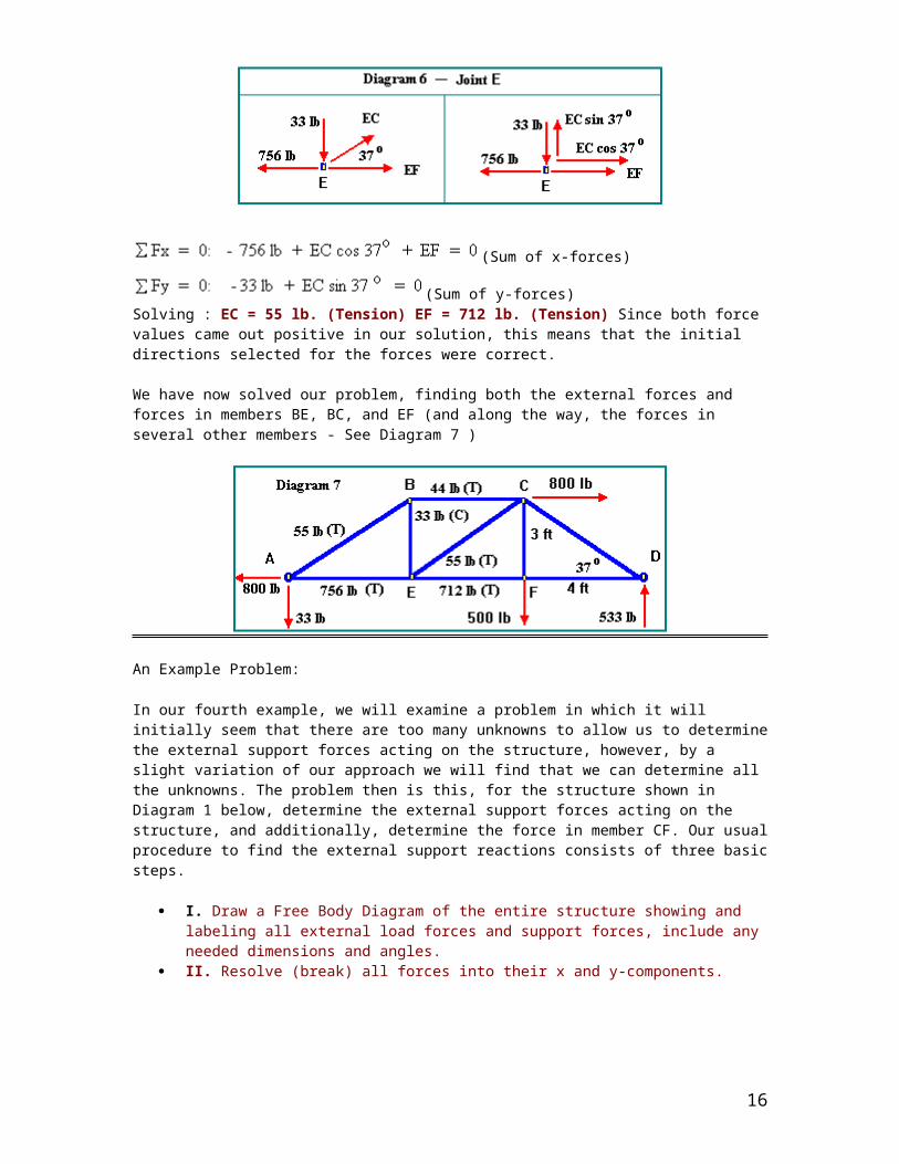
(Sum of x-forces)
(Sum of y-forces) Solving : EC = 55 lb. (Tension) EF = 712 lb. (Tension) Since both force values came out positive in our solution, this means that the initial directions selected for the forces were correct.
We have now solved our problem, finding both the external forces and forces in members BE, BC, and EF (and along the way, the forces in several other members - See Diagram 7 )
An Example Problem:
In our fourth example, we will examine a problem in which it will initially seem that there are too many unknowns to allow us to determine the external support forces acting on the structure, however, by a slight variation of our approach we will find that we can determine all the unknowns. The problem then is this, for the structure shown in Diagram 1 below, determine the external support forces acting on the structure, and additionally, determine the force in member CF. Our usual procedure to find the external support reactions consists of three basic steps.
I. Draw a Free Body Diagram of the entire structure showing and labeling all external load forces and support forces, include any needed dimensions and angles.
II. Resolve (break) all forces into their x and y-components.
III. Apply the Equilibrium Equations ( ) and solve for the unknown forces.
We note that the structure is composed of members ABC, DEF, DE, and CF. These members are pinned together at several points as shown in Diagram 1. A load of 6000 lb. is acting on member DEF at point E, and a load of 3000 lb. is applied at point F. These forces are already shown by the downward arrows. We next look at the forces exerted on the structure by the supports. Since each support is a pinned joint, the worst case we could have is an unknown x and y-force acting on the structure at each support point. We also must choose directions for the x and y support forces. In some problems the directions of the support forces are clear from the nature of the problem. In other problems the directions the support forces act is not clear at all. However, this is not really a problem. We simple make our best guess for the directions of the support reactions. If our guess is wrong, when we solve for the value of the support forces, that value will be negative.
13

This is important. A negative value when solving for a force does not mean the force necessarily acts in the negative direction, rather it means that the force acts in the direction OPPOSITE to the one we initially chose.
Step 1: Free Body Diagram (FBD).
In the FBD (Diagram 2), we have shown unknown x and y support forces acting on the structure at pinned support points A and D, (Ax, Ay, Dx, Dy). If we think ahead somewhat, we realize that there could be a problem. We have four unknown forces supporting the structure, but there are only three equations in our Equilibrium Conditions,
.
Normally, one can not solve for more unknowns then there are independent equations. Our first reaction should be to see if we can draw a better FBD. Perhaps we can replace the two unknowns at either point A or D by one unknown acting at a known angle (which is possible if we have a single axial member acting at the support point). However in this case both member ABC and member DEF are non-axial members, and the forces in them (and on them from the wall) do not act along the axis of the member. Thus, we already have the best FBD possible - we can not reduce the number of external unknowns acting on the structure.
At this point we will simply continue with our normal analysis procedure and see what results.
Step II: Resolve any forces not in the x or y-direction into x and y-components. (All forces are already in either
14

the x or y-direction.
Step III. Apply the Equilibrium conditions.
(Here we sum the x-forces, keeping track of their direction signs, forces to right, +, to left, -)
(Sum of y-forces, including load forces. Again keeping track of direction signs.)
Sum of Torque about a point. We choose point D. Forces Ay, Dx and Dy do not produce torque since their lines of action pass through point A. Thus, the torque equation has only one unknown, Ax. We solve for Ax, and then use it in the sum of forces in the x-direction equation to find the unknown, Dx . And if we do so, we find: Ax = +18000 lb. Dx = +18000 lb. (The positive signs indicate we initially chose the correct direction for the forces.) However, please notice that while we found Ax and Dx, we can not find Ay and Dy. There are still two unknowns in the y-equation and not enough information to determine then at this point. Thus, analysis of the structure as a whole has enabled us to determine several of the external support forces, but not all of them. What now?
First, an overview. There are problems for which the static equilibrium conditions are not enough to enable one to solve the problem. They are called Statically Indeterminate Problems, and we will be considering these a bit later. Then there are problems which, on first glance, appear to be statically indeterminate, but are not. That is the case here. To find the remaining unknown support forces (and at the same time, determining the force in member CF), we will now take out a member of the structure and apply our statics analysis procedure to the selected member of the structure (rather than the entire structure). We will select member ABC to analyze. (See Diagram 3)
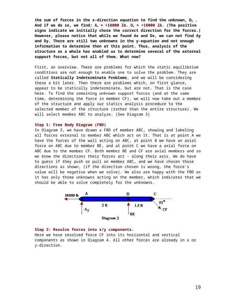
Step 1: Free Body Diagram (FBD) In Diagram 3, we have drawn a FBD of member ABC, showing and labeling all forces external to member ABC which act on it. That is at point A we have the forces of the wall acting on ABC, at point B we have an axial force on ABC due to member BE, and at point C we have a axial force on ABC due to the member CF. Both member BE and CF are axial members and so we know the directions their forces act - along their axis. We do have to guess if they push or pull on member ABC, and we have chosen those directions as shown, (if the direction chosen is wrong, the force's value will be negative when we solve). We also are happy with the FBD as it has only three unknowns acting on the member, which indicates that we should be able to solve completely for the unknowns.
Step 2: Resolve forces into x/y components. Here we have resolved force CF into its horizontal and vertical components as shown in Diagram 4. All other forces are already in x or y-direction.
Step 3. Apply the Equilibrium conditions.
15
We now solve the first equation for CF, then use that value in the last equation to find BE, and use both values in the middle equation to find Ay, giving us: CF = 30,000 lb., BE = 36,000 lb., Ay = -12, 000 lb. Please note that the value of Ay is negative, which indicates the direction we chose was incorrect. Ay acts downward rather than in the positive y-direction we initial chose. Additionally, we now can return to the equations for the entire structure (see below), and knowing the value for Ay, we can use it in the y-forces equation to solve for the value of Dy. Equilibrium Conditions for entire structure (from first part of problem)
From the y-forces equation: (-12,000 lb.) - Dy -6000 lb. -3000 lb = 0; Solving Dy = -21,000 lb.
Once again, the negative sign indicates we selected the wrong direction for Dy, rather than acting downward it actually acts upward. See Diagram 5 for final force values and directions. Ax = 18000 lb. Ay = 12,000 lb. Dx = 18000 lb. Dy = 21,000 lb. CF = 30,000 lb. BE = 36,000 lb.
The structure shown below is a truss which is pinned to the floor at point A, and supported by a roller at point D. For this structure:
A. Draw a Free Body Diagram showing all support forces and loads.B. Determine the value of all the support forces acting on the structure.C. Determine the force in member FC by method of joints.Unless otherwise indicated, all joints and support points are assumed to be pinned or hinged joints.
16

Solution:
PARTS A & B:
STEP 1: Draw a free body diagram showing and labeling all load forces and support (reaction) forces, as well as any needed angles and dimensions.STEP 2: Break any forces not already in x and y direction into their x and y components.STEP 3: Apply the equilibrium conditions.Sum Fx = Ax = 0Sum Fy = Ay + Dy - 12,000 lbs - 20,000 lbs = 0
Sum TA = (-12,000 lbs)(4 ft) - (20,000 lbs)(12 ft) + Dy(24 ft) = 0Solving for the unknowns: Dy = 12,000 lbs; Ay = 20,000 lbs
PART C - Now find internal force in member FC by method of joints.
17

JOINT D:STEP 1: Draw a free body diagram of the joint.STEP 2: Resolve all forces into x and y components (see diagram).STEP 3: Apply equilibrium conditions:Sum Fx = -CD + ED cos (66.4o) = 0Sum Fy = 12,000 lbs - ED sin (66.4o)= 0Solving for the unknowns:ED = 13,100 lbs (c); CD = 5,450 lbs (t)
JOINT E:STEP 1: Draw a free body diagram of the joint.STEP 2: Resolve all forces into x and y components (see diagram).STEP 3: Apply equilibrium conditions:Sum Fx = (-13,100 lbs) cos (66.4o) +FE - CE cos (66.4o) = 0Sum Fy = (13,100 lbs) sin (66.4o) - CE sin (66.4o) = 0Solving for the unknowns: FE = 10,500 lbs (c); CE = 13,100 lbs (t)
JOINT C:STEP 1: Draw a free body diagram of the joint.STEP 2: Resolve all forces into x and y components (see diagram).STEP 3: Apply equilibrium conditions:Sum Fx = 5,450 + (13,100 lbs) cos (66.4o) + FC cos (66.4o) - BC = 0Sum Fy = (13,100 lbs) sin (66.4o) - FC sin (66.4o) = 0Solving for the unknowns: FC = 13,100 lbs (c); BC = 15,950 lbs (t)
MORE TRUSS PRACTICE PROBLEMS:
Find the forces in the truss’s members in the following problems:
18
19

20

21