excalibur displacement piles
TRANSCRIPT

EXCALIBUR HIGH CAPACITY PILES
DYLAN ROBINSON, P.E.

All rights reserved © 2020 MacLean Power Systems.
EXCALIBUR HIGH CAPACITY PILES
• Communication Breakdown
• Product Overview
• Design Methodology
• Installation Procedure
T R E N T O N2

All rights reserved © 2020 MacLean Power Systems.
COMMUNICATION BREAKDOWN
• Request for a foundation pile comes in
• Send information to MPS sales person and myself
• Geotechnical report (boring log)
• Pile loading information
• Foundation plans/details
• I will review and provide a product recommendation and quote
• For finer points of installation, may require conference call with necessary parties and PW at my discretion
T R E N T O N6

All rights reserved © 2020 MacLean Power Systems.
EXCALIBUR PRODUCT OVERVIEW
• Displacement Pile
• Steel pi le that is torqued into the soil
• Multiple driver plates
• Capacity estimated by measuring torque and applying a torque factor
• Develops the majority of i ts axial resistance through end bearing on driver plates
T R E N T O N7

All rights reserved © 2020 MacLean Power Systems.
EXCALIBUR PRODUCT OVERVIEW
• Pressure Grouted Pile (DDM)
• Steel pi le that is torqued into the soil and encased in grout
• Single driver plate
• Grout delivered through ID of the pile as it is advanced in the soil
• Capacity is determined by the length and diameter of the grout column
• Develops the majority of i ts axial resistance through skin fr ict ion
T R E N T O N8

All rights reserved © 2020 MacLean Power Systems.
PRODUCT OVERVIEW
• Shaft
• Couplings
• Driver plate(s)
• Grout
• Termination
T R E N T O N9

All rights reserved © 2020 MacLean Power Systems.
SHAFT
• 4.5” to >9.625” OD pipe
• 10’ – 40’ lengths
• 80 ksi yield strength
• Seamless pipe
• Displaces soil
• No vibrations
• Galvanizing available
T R E N T O N10

All rights reserved © 2020 MacLean Power Systems.
COUPLINGS
• Bolted
• Threaded
T R E N T O N11

All rights reserved © 2020 MacLean Power Systems.
DRIVER PLATE(S)
• 8” – 30” diameter
• ½” – ¾” thick
• 6” pitch
• Help to advance to the pile
• Create annulus for grout column
• End bearing
T R E N T O N12

All rights reserved © 2020 MacLean Power Systems.
GROUT
• Neat grout mix
• 4,000 psi min yield
• Delivered through ID of pile during installation
• Able to control bonded length
T R E N T O N13

All rights reserved © 2020 MacLean Power Systems.
TERMINATIONS
• Stationary bolted top plates
• Adjustable top plates
• Nelson studs
T R E N T O N14

All rights reserved © 2020 MacLean Power Systems.
CAPACITY CHART – DISPLACEMENT PILES
T R E N T O N15
Catalog
Number
Pipe Dimensions
(in)
Ultimate Axial
Capacity (kips)*
Ultimate Torque
Rating (ft-lb)*Kt factor (ft-1)
H45/T45 4.5 x 0.290 184 35,000 6
H55/T55 5.5 x 0.415 318 65,000 5
H70/T70 7 x 0.408 406 122,000 4
H76/T76 7.625 x 0.500 537 150,000 3.9
H96/T96 9.625 x 0.545 746 250,000 3.1
*Ratings vary based on coupler configuration, grade of steel
H – bolted couplersT – threaded couplers

All rights reserved © 2020 MacLean Power Systems.
7” OD pile, Kt = 4
• Pile installed to 45’
• Average torque over final 3’
• 18,000 ft- lbs
18,000 ft-lbs x 4 ft -1 = 72,000 lbs
4.5” OD pile, Kt = 6
• Pile installed to 30’
• Average torque over final 3’
• 25,000 ft- lbs
25,000 ft-lbs x 6 ft -1 = 150,000 lbs
T R E N T O N16
TORQUE TO CAPACITY EXAMPLE
Installation torque is a direct measurement of the soil’s shear strength that
the plates are embedding into

All rights reserved © 2020 MacLean Power Systems.
CAPACITY CHART – PRESSURE GROUTED PILES (DDM)
T R E N T O N17
Catalog
Number
Pipe Dimensions
(in)
Ultimate Torque
Rating (ft-lb)*
Grout Column
Diameter (in)*
Grout Take
(yd3 per ft)
Ultimate
Compression (kips)*
Ultimate
Tension (kips)*
G45/W45 4.5 x 0.290 35,000 16 0.05 428 169
G55/W55 5.5 x 0.415 65,000 18 0.07 607 292
G70/W70 7 x 0.408 122,000 20 0.08 764 372
G76/W76 7.625 x 0.500 150,000 22 0.1 958 492
G96/W96 9.625 x 0.545 250,000 24 0.11 1,230 684
*Ratings vary based on coupler configuration, grade of steel, groutG – bolted couplersW – threaded couplers

All rights reserved © 2020 MacLean Power Systems.
APPLICATIONS
• Bridge abutments
• Commercial building foundation
• High axial and/or lateral loads
• Areas with poor upper soil layers
• Contaminated soils
T R E N T O N18
All rights reserved © 2020 MacLean Power Systems.
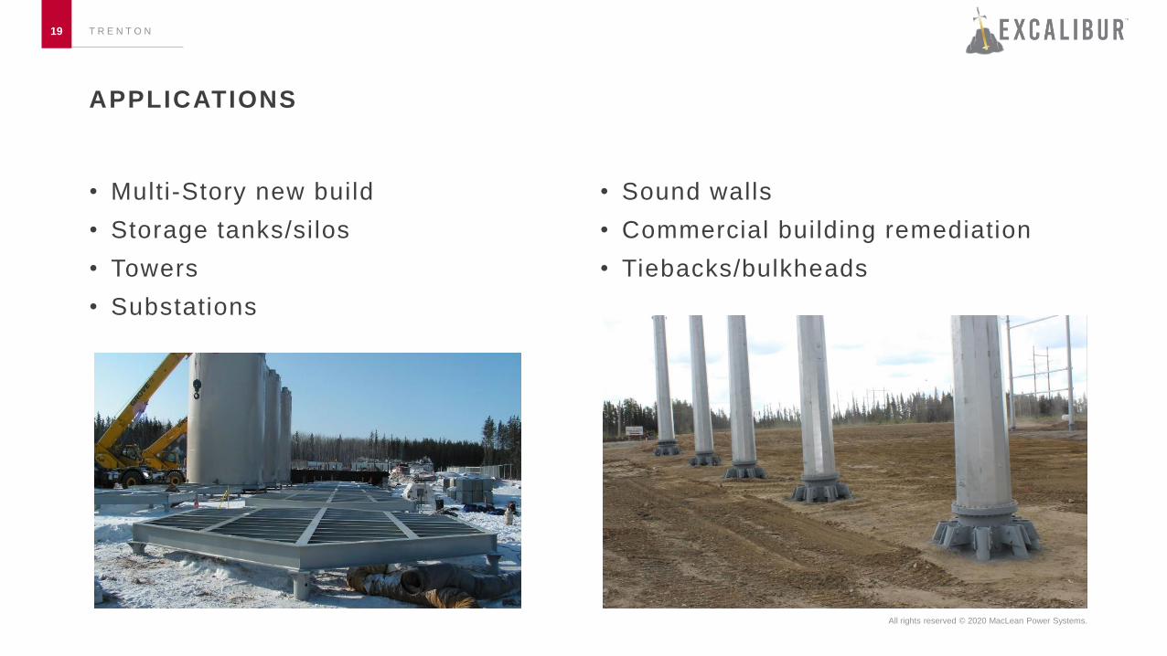
APPLICATIONS
• Multi-Story new build
• Storage tanks/silos
• Towers
• Substations
• Sound walls
• Commercial building remediation
• Tiebacks/bulkheads
T R E N T O N19

All rights reserved © 2020 MacLean Power Systems.
T R E N T O N20

All rights reserved © 2020 MacLean Power Systems.
T R E N T O N21

All rights reserved © 2020 MacLean Power Systems.
T R E N T O N22

All rights reserved © 2020 MacLean Power Systems.
HIGH CAPACITY PILE CASE STUDIES
• Louisiana
• 115 kV Substation
• 5.5” x 0.415” Grouted piles
• 35’ deep with 16” grout column
• Very soft clay and silt
• 70 kips compression
• 7 kips lateral, 140 ft -kips moment
• New York
• 20,000 Gallon Dielectric Fluid Tank
• 5.5” x 0.415” Grouted piles
• 25’ deep with 12” grout column
• Very dense misc. fi l l in upper 20’ followed by very dense glacial ti l l
• 80 kip compression, 40 kip uplift
• 0.3” deflection under load
T R E N T O N23

All rights reserved © 2020 MacLean Power Systems.
NEW YORK
T R E N T O N24
All rights reserved © 2020 MacLean Power Systems.
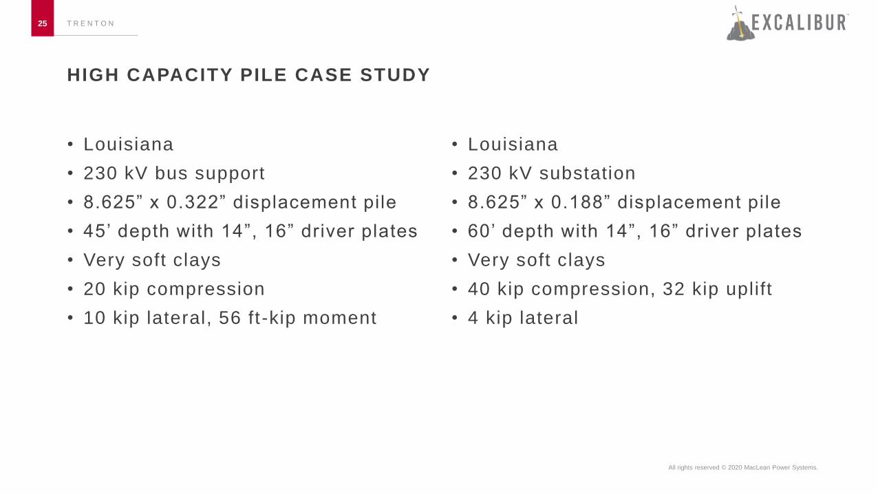
HIGH CAPACITY PILE CASE STUDY
• Louisiana
• 230 kV bus support
• 8.625” x 0.322” displacement pile
• 45’ depth with 14”, 16” driver plates
• Very soft clays
• 20 kip compression
• 10 kip lateral, 56 ft -kip moment
• Louisiana
• 230 kV substation
• 8.625” x 0.188” displacement pile
• 60’ depth with 14”, 16” driver plates
• Very soft clays
• 40 kip compression, 32 kip uplift
• 4 kip lateral
T R E N T O N25

All rights reserved © 2020 MacLean Power Systems.
T R E N T O N26

All rights reserved © 2020 MacLean Power Systems.
BUCKET PILE CASE STUDIES
• Galveston, TX
• 69 kV
• 7” pipe x 7’ lead section
• 18” driver plate
• 24” bucket x 9’
• Grouted
• 61 kip compression
• 4 kip shear, 180 ft-kip moment
• New Jersey rail crossing
• 69 kV
• 7.625” x 9’ lead section
• 14”, 16” double driver plate
• 30” x 13’ bucket section
• Concrete collar
• 55 kip compression, 13 kip uplift
• 8 kip shear, 310 ft-kip moment
T R E N T O N27

All rights reserved © 2020 MacLean Power Systems.
T R E N T O N28

All rights reserved © 2020 MacLean Power Systems.
T R E N T O N29

All rights reserved © 2020 MacLean Power Systems.
DESIGN METHODOLOGY
• Allowable Stresses• Displacement pile
• Helical pi le – IBC
• Pressure grouted pile (DDM)
• Micropile – FHWA/IBC
T R E N T O N30
• Geotechnical Capacity• Terzaghi’s general bearing
formula
• Skin friction calculations
• LPILE analysis

All rights reserved © 2020 MacLean Power Systems.
IBC – DISPLACEMENT PILE
T R E N T O N31

All rights reserved © 2020 MacLean Power Systems.
IBC – PRESSURE GROUTED PILE (DDM)
T R E N T O N32

All rights reserved © 2020 MacLean Power Systems.
PRESSURE GROUTED PILE (DDM) – FHWA NHI-05-039
T R E N T O N33

All rights reserved © 2020 MacLean Power Systems.
GEOTECHNICAL CALCULATIONS
• Terzaghi’s general bearing formula
• Skin friction formulas
• FHWA skin friction formula
T R E N T O N34

All rights reserved © 2020 MacLean Power Systems.
BOND STRENGTHS
• Type B – pressure grouted
• Most effective in areas with medium dense to dense sand and gravel
Table 5-3 FHWA NHI -05-039
T R E N T O N35

All rights reserved © 2020 MacLean Power Systems.
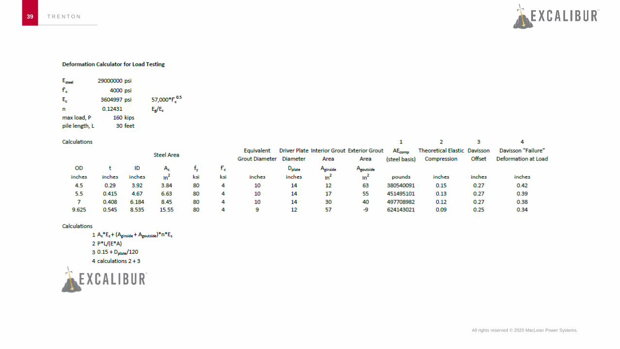
ADDITIONAL CALCULATION
• Davisson Failure Deformation
• Estimate pile deflection during load test
• Flexural capacity
• Verify al lowable axial and moment capacit ies of shaft are suff icient
• Buckling capacity
• Verify pi le wil l not buckle in areas with low consistency (N<5) soils
• Ensoft’s LPILE
• Program used to determine lateral capacity and pile head deflection
T R E N T O N36

All rights reserved © 2020 MacLean Power Systems.
PRODUCT RECOMMENDATION PACKET
T R E N T O N37
• Summarizes assumptions and mechanical/geotechnical inputs
• Shows calculations and code references

All rights reserved © 2020 MacLean Power Systems.
T R E N T O N38
All rights reserved © 2020 MacLean Power Systems.
T R E N T O N39

All rights reserved © 2020 MacLean Power Systems.
T R E N T O N40

All rights reserved © 2020 MacLean Power Systems.
T R E N T O N41

All rights reserved © 2020 MacLean Power Systems.
T R E N T O N42

All rights reserved © 2020 MacLean Power Systems.
INSTALLATION PROCEDURE – DISPLACEMENT
• Key Points:
• Record and monitor torque and depth
T R E N T O N43

All rights reserved © 2020 MacLean Power Systems.
INSTALLATION PROCEDURE – PRESSURE GROUTED PILE (DDM)
• Key points:
• Record and monitor grout take and pressure
T R E N T O N44

All rights reserved © 2020 MacLean Power Systems.
INSTALLATION PROCEDURE
T R E N T O N45

All rights reserved © 2020 MacLean Power Systems.
TYPICAL SITE LAYOUT
T R E N T O N46
GROUT PUMP
VOLUMETRIC MIX TRUCK PILING INSTALL AND MATERIAL HANDLING EQUIPMENT

All rights reserved © 2020 MacLean Power Systems.
PRESSURE GROUTED PILE INSTALLATION TOOLING
10 – 45 ton excavators most common
T R E N T O N47

All rights reserved © 2020 MacLean Power Systems.
DISPLACEMENT PILE INSTALLATION EXAMPLES
T R E N T O N48

All rights reserved © 2020 MacLean Power Systems.
ON-SITE LOAD VERIFICATION
• Static axial load test – ASTM D1143 & D3689
• Increase applied axial force to 200% design load
• Monitor deflection
T R E N T O N49

All rights reserved © 2020 MacLean Power Systems.
ON-SITE LOAD VERIFICATION
• Static lateral load test – ASTM D3966-07
• Increase applied axial force to 200% design load
• Monitor deflection
T R E N T O N50

All rights reserved © 2020 MacLean Power Systems.
ON-SITE LOAD VERIFICATION
T R E N T O N51
All rights reserved © 2020 MacLean Power Systems.
QUESTIONS?
• 205-572-0856
T R E N T O N52

THANK YOU!
FOR MORE INFORMATION PLEASE V IS IT
MACLEANPOWER. COM/PRODUCT/ANCHORS -UTIL ITY