excavation of tunnels for flood control in buenos aires...
TRANSCRIPT
Excavation of Tunnels for Flood Control in Buenos
Aires, with a TBM Oscar Alberto Vardé Academia Nacional de Ingeniería Argentina, President Vardé y Asociados S.A., President, Buenos Aires, Argentina Rodolfo Eduardo Guidobono Vardé y Asociados S.A., Buenos Aires, Argentina ABSTRACT The city of Buenos Aires planned the construction of a hydraulic system to control the floods in the Maldonado Creek basin, which is part of the City Hydraulic Master plan. The project comprises the construction of two tunnels of 6,90 m internal diameter, 4,5 km and 10 km long, access shafts and connecting and discharge chambers. The tunnels alignments intersect a heterogeneous soil profile with hard silts, stiff plastic clays, silty sands, and sands. The shorter tunnel is already finished and the other one is still under construction, both of them bored with TBM and EPB procedures. The geotechnical challenge due to the presence of a semiartesian aquifer was solved with a substantial change in the design of the main access shaft. There are described herein the main features of the project and the construction methods which have taken into account the ground conditions, the obstacles to be found in the excavation of the tunnels and environmental impact. RESUMEN La construcción de los túneles aliviadores del Emisario Principal del Arroyo Maldonado es la obra más importante encarada por el Gobierno de la Ciudad Autónoma de Buenos Aires, siendo un elemento fundamental del Plan Director Hidráulico. Consta de 2 túneles de 6,90 m de diámetro interno, de 4,5 km y 10 km de longitud, excavados con dos máquinas tuneleras TBM utilizando procedimientos EPB, cámaras de descarga y conexión y pozos de acceso. Se describen en este trabajo las características fundamentales del proyecto, explicitando los métodos constructivos, adoptados en función de las características geotécnicas, las condiciones existentes edilicias, las interferencias y el impacto ambiental. 1 INTRODUCTION The construction of two tunnels to control the floods in the Maldonado Creek basin is the most important project carried out presently by the Buenos Aires Government.
They are part of the City Hydraulic Master Plan; its aim is the mitigation and control of urban floods due to intense rainstorms. In January 2001 140 mm poured in 3 hours; affecting more than 100.000 buildings and 300.000 inhabitants. Since 1985 more than 35 floods occurred in the area, causing 25 deaths and millions of dollars of damages.
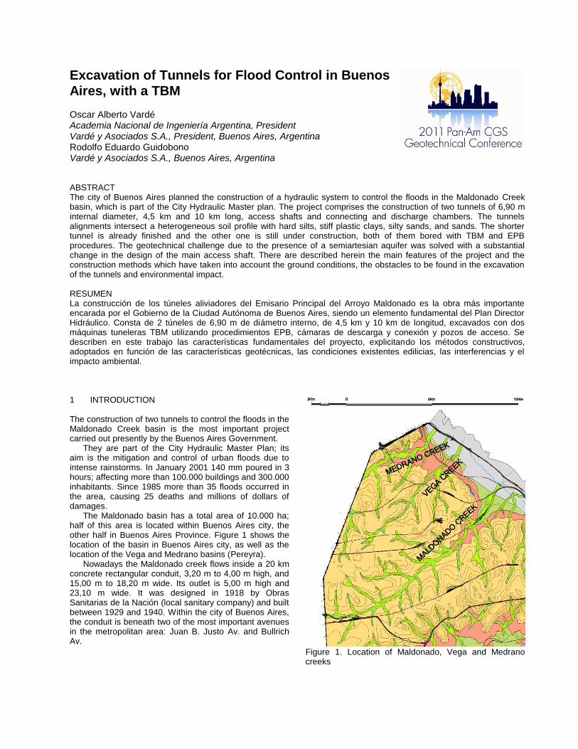
The Maldonado basin has a total area of 10.000 ha; half of this area is located within Buenos Aires city, the other half in Buenos Aires Province. Figure 1 shows the location of the basin in Buenos Aires city, as well as the location of the Vega and Medrano basins (Pereyra).
Nowadays the Maldonado creek flows inside a 20 km concrete rectangular conduit, 3,20 m to 4,00 m high, and 15,00 m to 18,20 m wide. Its outlet is 5,00 m high and 23,10 m wide. It was designed in 1918 by Obras Sanitarias de la Nación (local sanitary company) and built between 1929 and 1940. Within the city of Buenos Aires, the conduit is beneath two of the most important avenues in the metropolitan area: Juan B. Justo Av. and Bullrich Av.
Figure 1. Location of Maldonado, Vega and Medrano creeks

Due to the demographic growth and to the subsequent building constructions, the subsoil absorption is practically insignificant, and therefore the drainage system of the Maldonado basin has been insufficient for many decades. Quite often a south-east wind known as “Sudestada” occurs simultaneously with heavy storms, causing a rise of the level of the Río de la Plata and the ensuing flowing of the water from this river into the conduit, preventing the normal stream of the Maldonado creek (and of the other creeks).
At the present time a rainfall intensity of 52 mm in 3 hours, which has a return period of 2 years, would cause flooding of a significant area of the basin. The new alleviation flood tunnels will prevent the effects caused by such floods, and will attenuate to a minimum level the damages due to rainstorms of a 10 years recurrence (81 mm in 3 hours).
There are described herein the main characteristics of the project, the construction methods, the geotechnical site conditions, and the special procedures adopted to cross below other underground structures and preserve old constructions existing along the tunnels alignments.
The contractor is Ghella S.p.A., from Italy. Vardé y Asociados acts as geotechnical consultants to the Contractor and is in charge of the geotechnical investigations and installation of the monitoring system. Geodata, an Italian consultant firm, and CADIA, an argentine consultant firm, are in charge of the works inspection. General supervision is responsibility of the engineering staff of the Ministry of Public Works of the Buenos Aires City Government. 2 PROJECT DESCRIPTION The original design and the preparation of the contract documents for the bidding were made by the joint venture of the consultant firms Halcrow-Harza-Iatasa-Latinoconsult.
The project consists of two tunnels with an internal diameter of 6,90 m, which are bored with two TBM, using EPB procedures.
The tunnel Number One (Short Tunnel) has a length of 4,5 km, between the access shaft Nº 1 (located in the site named Punta Carrasco by the Río de la Plata shore) and the Niceto Vega shaft (constructed in the intersection of Niceto Vega Street and Juan B. Justo Avenue). The excavation and lining of this tunnel were finished in September 2010.
The tunnel Number Two (Long Tunnel), 10 km length, was also bored from the access shaft Nº 1, to the Cuenca
shaft (currently under construction in the intersection of Cuenca street and Juan B. Justo avenue). In February 2011 this tunnel has reached a length of 4,5 km.
The alignments of both tunnels are shown in Figure 2, they have minimum horizontal radius of curvature of 300 m. Their profile should have taken into consideration the existing underground constructions (“B” and “D” metro lines, and a major water supply tunnel), several buildings, three bridges and a highway foundations, the Buenos Aires metropolitan airport and the Maldonado conduit.
The project also includes three derivation structures, one ventilation shaft over each tunnel, a pumping structure and a discharge channel from the access shaft Nº 1 to the Río de la Plata.
3 GEOTECHNICAL CONDITIONS A thorough geotechnical investigation had been carried out by Vardé y Asociados (Capdevila et al.). It comprised 104 borings 30 to 45 meter deep, located at a spacing of approximately 100 m along the alignment, and at the shafts locations as well as the sites where the tunnels crossed under existing structures.
The soil stratigraphy is described below (the elevations in this paper are referred to the argentine Military Geographical Institute zero):
a) Soft to medium stiff silty clays from the ground level (elevation +12,00 at the Cuenca shaft, elevation +4,00 m at the access shaft Nº 1) down to an elevation of +6,00 / +4,00 m. Near the Río de la Plata there is an upper stratum 5 to 7 meters thick of soft clays and heterogeneous backfill.
b) Under these strata there is a preconsolidated by desiccation cemented loess (Pampeano Formation), locally known as “tosca”. A remarkable feature in this case is the presence of erratic interbedded layers of silty sands close to the tunnel sections.
c) Beneath the “tosca” there is a layer of stiff plastic clays 2,00 m to 4,00 m thick, which is underlain by the very dense sands of the Puelchense Formation. The bed level of this formation is at a depth between 25 and 35 meters.
The phreatic level is at +10,00 m elevation in the Cuenca shaft and at +3,00 m elevation near the Río de la Plata.
As an example of the general stratigraphy, the Figure 3 and the Figure 4 show the geotechnical profile near the access shaft Nº 1 and the Cuenca shaft.
Figure 2. Alignment of Relief tunnels: Number One (Short Tunnel) and Number Two (Long Tunnel)

Figure 3. Longitudinal geotechnical profile – Tunnel Nº 1 (Short Tunnel), near Access Shaft Nº 1

Figure 4. Longitudinal geotechnical profile – Tunnel Nº 2 (Long Tunnel), near the Cuenca Shaft
The “puelchense” sands are a confined aquifer, whose semiartesian pressure is similar to the phreatic level. Due to this feature, to the presence of interbedded layers of silty sands in the stiff silts of the Pampeano Formation, and to the extremely sensitive existing infrastructure, the use of TBM with EPB procedure was selected to carry out this project. It would be worthwhile to point out that in Buenos Aires city the boring of the metro lines is carried out by Subterráneos de Buenos Aires (local metro company) using NATM procedures or cut-and-cover methods.
Before the beginning of the works, Vardé y Asociados carried out additional geotechnical investigations at the locations of the shafts. Special attention was paid to the Punta Carrasco area, where the access shaft Nº 1 was located. Four borings 60 m to 75 m deep were carried out in order to obtain geotechnical data of the layers beneath the Puelchense Formation. Special samples using Denison samplers were taken in order to perform permeability tests and triaxial drained and undrained tests. The Figure 7 shows the log from one of these

borings. The geotechnical profile in this site is hereinafter described:
a) G.L. (+4,00 m) to +0,00 m elevation: backfill b) +0,00 m elevation to -20,00 m elevation: stiff to
very stiff silts and silty clays c) -20,00 m elevation to -22,00 m elevation: stiff
plastic clays d) -22,00 m elevation to -46,00 m elevation: very
dense sands e) -46,00 m elevation to -61,00 m elevation: stiff
plastic clays, from the Miocene period. f) below -61,00 m elevation: very dense sands Hydrogeological studies confirmed the hypothesis that
the phreatic level is very similar to the aquifer levels. The geotechnical conditions at the site of the Cuenca
shaft are similar to the described above. In this shaft the clay strata beneath the puelchense aquifer is 10 meters thick, between elevations -40,00 m and -50,00 m. 4 CONSTRUCTION METHODS 4.1 TUNNELS Tunnels are bored with two TBM using EPB procedures. The boring diameter is 7,90 m.
The equipment, made by Lovat, from Canada, model ME310SE, has a TBM 10 meters length and 900 tons weigh plus a back up, with a total length of 105 meters. It consumes 3,5 MW.
The Figure 5 shows a detailed section of the TBM. The cutting head excavate the ground and the soil is
mixed under pressure with the polymer in the chamber, from where is extracted by a screw conveyor. The chamber pressure is controlled by the rate of advance of the machine and the rate of extraction of the excavated ground by the screw conveyor. The machine advances with the thrust generated by jacks acting against the tunnel lining.
The contract documents include severe limitations on the settlement tolerances that could be produced by the tunneling. In order to keep the settlements below the limits, special procedures are strictly followed:
a) Adequate use of the polymer; the mix of these products with the soil should have the consistency to control the entry of soil within the chamber avoiding the loss of ground and also to facilitate the extraction of the material by the screw conveyor.
b) Immediate grouting of cement mixings in the annulus space between the cutting head diameter and the external tunnel diameter, which in this case is 10 to 15 cm thick.
c) Grouting of grease behind the rear end of the shield, where there are three lines of steel brushes, in order to prevent the pouring of the cement grouting into the tunnel.
The excavated soil is transported by trains to the access shaft Nº 1 where it is pumped to the ground level, and placed in trucks to be transported to a reclamation area outside the Buenos Aires metropolitan area.
The alignment of the tunnels, the weight of the excavated soil, the pressure in the chamber, the pressure of the hydraulic thrust, the volumes of the cement grouting and of the grease, are all controlled in real time on the Contractor and on the Work Inspection facilities, in Buenos Aires, and on the headquarters of the Contractor in Italy.
The tunnel lining consists of 7 segments, 0,35 m thick and 1,50 m long. These segments are different shaped from each other, and geometrically design in order to allow the construction of the bends of the tunnel.
The average performance of the tunnel excavation and lining is over the 20 meters per day, with a maximum of 40 meters per day and a maximum of 710 meters in a month.

Figure 5. Lovat TBM, model ME310SE
4.2 ACCESS SHAFTS There are described in this chapter the access shaft Nº 1 and the Niceto Vega shaft, which are already finished. Cuenca shaft is currently under construction. 4.2.1 Access Shaft Number One The access shaft Nº 1 is located at the site known as Punta Carrasco, by the Río de la Plata shore. Figure 6 shows its vertical section and Figure 7 shows the log of one of the borings carried out at this site.
This shaft was originally designed with 3 contiguous circular shafts, each with a diameter of 15 meters, with diaphragm walls 35 meter deep and a bottom slab cast under water at a depth of 30 meters, within the bed of the Puelchense Formation. Because of the risk of sand piping through potentially flawed diaphragm walls-bottom slab contacts, triggered by the high piezometric pressures (there were historical cases in Buenos Aires in which severe damage occurred by piping), Ghella substantially change the design of this shaft: The horizontal section was changed to a circular
one with a diameter of 40 meters. The perimeter diaphragm wall was constructed
down to a depth of 55 meters, with an embedment of 5 meters in the miocenic stiff plastic clays. This clay layer worked as an lower plug, since the permeability tests results show that the clay was relatively impervious (permeability circa 10
-10 m/s).
Figure 6. Vertical section of Access Shaft Nº 1

Figure 7. Boring log at the site of the Access Shaft Nº 1

The diaphragm wall was 1,20 m thick and was constructed using a hydromill (Soilmec model Tiger H-8, portrayed in Figure 8) by Pilotes Trevi S.A., a local branch of the italian company Trevi S.p.A. During the construction of each 2,80 m length panel strict controls of verticality were carried out using DMS (Drilling Mate System). The use of the hydromill excavating directly on the concrete of the primary panels permitted a much better joint with the secondary panel than the conventional methods using clamshell equipments. The continuity of the concrete was checked by cross-hole procedures.
Figure 8. Hydromill
With the aforementioned procedures it was possible, for the first time in Buenos Aires, to excavate on dry down to the “puelchense” sands avoiding the usual practice of casting under water the bottom slab of the shaft. In some previous cases casting under water caused piping of sand and the consequent loss of ground from the Puelchense aquifer.
A monitoring system including phreatimeters and piezometers, pictured in Figure 14, was installed before the beginning of the works, for the control of the levels of
the underground water within and outside the shaft. The instruments installed on the outside showed throughout the construction that the pumping from the interior of the shaft did not influence these levels. The inclinometers showed practically no deformation of the walls during and after the construction of the shaft.
The steel reinforcement of the walls had been replaced by fibreglass bars in the tunnel break-in sector. This material has a resistance similar to the steel but is much easily cut by the head of the TBM.
4.2.2 Niceto Vega Access Shaft This shaft is cylindrical with a 15,00 m interior diameter and a depth of 22 meters.
Figure 9 shows a typical boring log of this site. The stratigraphy is described below:
a) G.L. (+8,00 m) to elevation +3,00 m: soft clays b) +3,00 m elevation to -20,00 m elevation: stiff to
very stiff silty clays and silts, with a layer of dense silty sands between elevations -13,00 m and -16,00 m
c) -20,00 m elevation to -24,00 m elevation: transition materials: stiff clays with interbedded lenses of silty sands
d) below -24,00 elevation: very dense “puelchense” sands.
The underground water was found at +3,70 m elevation.
Before the excavation, 32 bored piles 1,00 m diameter and 30,00 m deep was installed along the perimeter of the shaft with a separation between each other of 0,30 m. In 8 piles, in the break-out section of the tunnel, the steel reinforcement was replaced by fibreglass bars. The spaces between piles below a depth of 22 meters were injected with cement grouting, using the method “á manchettes”, due to the presence of the silty sands layer which was found, as expected, 0,50 m above the bottom level of the excavation. Figure 10 shows the positions of the piles and the grouting borings. The monitoring system comprises phreatimeters and piezometers. The information obtained from these instruments showed that the silty sand layer was not directly connected to the “puelchense” aquifer. Therefore it was possible to dewater the excavation with deep wells installed outside the shaft, complemented with direct pumping inside. As the grouting between piles was not sufficient to control the silty sand layer seepage into the shaft, Ghella installed metal plates between the piles, from a depth of 21 meters. This procedure was successful and the contractor was able to reach the bottom level of the shaft without any further inconvenience.
On September 10th, 2010 the TBM break out at Niceto Vega shaft, finishing the boring of the Tunnel Nº 1.

Figure 9. Boring log at Niceto Vega shaft
Figure 10. Niceto Vega Shaft – horizontal section
4.2.3 Crossing under Existing Tunnel As an example of the control made for the construction of the tunnels below existing underground infrastructures it is described herein the under-cross of the Tunnel Nº 1 7,80 m below a major tunnel for water supply, which belongs to AySA, the local water and sewer public company. This conduit is a circular concrete tunnel 4,60 m interior diameter; the concrete lining is 0,46 m thick. The crossing was at the station 1+939 of the Tunnel Nº 1, almost below the Palermo lake (shallow lake with a couple meters of water depth). In the Figure 11 and the Figure 12 there are shown the location and the longitudinal section of the crossing.

Figure 11. Location of the crossing of the Tunnel Nº 1 under the underground river
Figure 12. Longitudinal section of the crossing of the Tunnel Nº 1 under the existing tunnel for water supply
The geotechnical profile is similar to the one showed in the Figure 3, with an upper stratum 3 meter thick of backfill materials, beneath which there are stiff cohesive soils (Pampeano Formation). The bed of the Puelchense Formation is at an elevation of -23,00 m, with a transition layer between these two formations of sandy silts, sandy clays and silty sands. The underground water lever was found at +0,00 m elevation.
The tunnel Nº 1 was in transition materials and in the “puelchense” sands.
The monitoring of the crossing is showed in Figure 15 and in Figure 16.
The Table Nº 1 contains the settlements registered by the monitoring system between the Access Shaft Nº 1 and 0+900 station.
Table 1. Settlements ( ) registered between Access Shaft Nº 1 and 0+900 station
Station Instrument (mm) 0+048 AM-10 1 a 3 0+087 AM-02 < 1 0+190 AM-03 1 0+244 AM-04 1 0+540 AM-05 1 a 3 0+856 AM-06 < 1 0+896 AM-07 < 1
The values registered at different depths by each in-
place extensometers reveal that the settlements were below the limits and that they do not differ substantially with the depth at any station of the alignment, i.e. it could be assumed that the settlement was uniform with the depth.
The deformation of the ground began when the TBM reached the station of each instrument, and became stable when the tunnel face was beyond a distance equal to 3 or 4 times the tunnel diameter.
With a finite element analysis it was estimated that the tensile stresses in the underground river would have been approximately 7,5 kg/cm
2 for a settlement of this conduit
of 4 mm. The stress was considered admissible. Even though it was proved that the construction of the
Tunnel Nº 1 could have been carried out with the normal procedures since it had produced settlements less than 3 mm, the contractor used special methods, with the use of higher chamber pressures and lower rates of advance of the TBM than in normal sections. The settlements at the crossing were less than 2 mm, at the surface, at the elevation of the existing tunnel for water supply, and at the keystone of the Tunnel Nº 1. 5 MONITORING The monitoring system comprises the following instruments:
a) Inclinometers, installed down to a couple of meters below the tunnel.
b) Settlement gauges – in-place extensometers, installed over the alignment of the tunnel, down to a couple of meters over the keystone of the tunnel.
c) Piezometers. A set of two Casagrande tips were installed on each one of the piezometers: the inferior Casagrande tip was generally installed in the aquifer, whilst the other one was installed at a depth near the tunnel keystone.
d) Phreatimeters e) Points for surface settlement measure, located
along certain cross sections, in order to assess the settlement trough.
f) Points fixed to existing structures, in order to evaluate the impact on them of the construction of the tunnel.
Figure 13 shows a typical monitoring section, with one in-place extensometer (AM), one piezometer (PZ) and 8 points for surface settlement measurement (PMMS).

Figure 13. Typical monitoring section
Tables 2 and 3 include the number of instruments installed and to be installed for both tunnels. This prevision is being constantly updated; e.g. instruments installed in correspondence with station where the TBM should stop for maintenance tasks, or as required by the Client or the inspection.
Table 2. Number of Instrument to be installed as of March 2010 along the Tunnel Nº 1 alignment - AM: in-place extensometers; IN: inclinometers; PZ: piezometers; FR: phreatimeters
Station Number of Instruments
(m) AM IN PZ FR
20 1 1
100 1
550 3 1
1000 1
1450 4 4 1
1900 2 2
2350 1 1 1 1
2800 4 1 3 2
3700 1
4150 2 2 1 5
Total 19 6 12 9
Table 3. Number of Instrument to be installed as of March 2010 along the Tunnel Nº 2 alignment
Station Number of Instruments
(m) AM IN PZ FR
50 1 1
200 1
650 3 1
1100 1 1
1550 4 3 1
2000 1 2
2450 1 1 1 1
2900 3 1 3 2
3800 1
4250 1 1
4700 1 1 1
5150 4 1 2
5600 1
6050 1 1 1 1
6500 1
7400 1
8300 1 1
8750 1
9200 1
9650 1 1 1 1
Total 28 9 16 8
In Figure 14 it is shown the monitoring system at the site of the access shaft Nº 1. Figure 15 and Figure 16 shows the instruments at the crossing of the Tunnel Nº 1 under the AySA underground river: in-place extensometers (AM), points for surface settlement measurement (PMMS), phreatimeters (FR), piezometers (PZ).
Figure 14. Monitoring system at Access Shaft Nº 1

Figure 15. Monitoring system at under-cross of AySA tunnel for water supply (Tunnel Nº 1); plant. PMMS: points for surface settlement measurements; FR: phreatimeters; PZ: piezometers; AM: in-place extensometers
Figure 16. Monitoring system at under-cross of AySA tunnel for water supply (Tunnel Nº 2); cross-section. PMMS: points for surface settlement measurements; FR: phreatimeters; PZ: piezometers; Captor: Casagrande tip; AM: in-place extensometers 6 CONCLUSIONS The experience already acquired in the Maldonado Project confirms that the use of the TBM with EPB equipments is appropiate and the best solution in this case, considering the geotechnical features, the presence
of old urban underground services and structures, and the environmental conditions.
The follow up of excavations on line and the monitoring of ground movements by the extensive system of installed instruments was esential to control and confirm that the settlements and movements of the ground and the subsoil due to tunnel construction were practically insignificant.
The construction procedures followed on the
excavation of Access Shaft Nº 1 were a major improvement on the traditional methods used in Buenos Aires in similar conditions, allowing the safe excavation on dry of the aquifer with artesian pressure of the Puelchense Formation for the first time. ACKNOWLEDGEMENTS The writers would like to acknowledge the contribution of Gustavo Dascoli and Fernando de Rubeis, from Ghella. REFERENCES Pereyra, F.X.; 2001; Mapa Geológico Ciudad de Buenos
Aires; Convenio Facultad de Ciencias Exactas y Naturales UBA y Secretaría de Planeamiento Urbano GCABA.
Capdevila, E.O.; Barletta, R.H.; Guidobono, R.; Guichón, M.E.; King, M.; 2010; Geotecnia para túneles en la cuenca del arroyo Maldonado; Proceedings CAMSIG 2010: 39-45.