excavation safety good practice guidelines · pdf fileexcavation safety key points: avoid...
TRANSCRIPT
JULY 2016
Excavation Safety
GOOD PRACTICEGUIDELINES
HSWA• H
EA
LTH
& SAF ET Y AT W
OR
K A
CT
•

This guideline provides practical guidance to manage health and safety risks associated with excavation work.
ACKNOWLEDGEMENTS
WorkSafe New Zealand (WorkSafe) would like to thank Safe Work Australia for letting us use content and images from their model code of practice Excavation Work.
WorkSafe would like to thank the following for their input and involvement in the development of this guideline:
> Beca Ltd
> Brian Perry Civil
> Civil Contractors New Zealand
> Connexis
> Construction Contracts Limited
> E Carson & Sons Limited
> Electricity Engineers’ Association
> FIRST Union
> Goodman Contractors Ltd
> HEB Construction Ltd
> Safety’n Action Ltd
> Trench Shoring New Zealand Ltd.
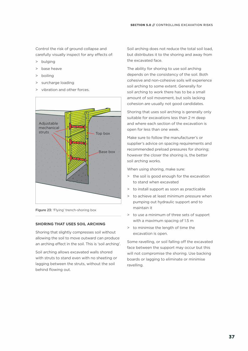
Special thanks to SCIRT (Stronger Christchurch Infrastructure Rebuild Team) for the use of the cover photo. Copyright Neil MacBeth, licensed to SCIRT.
Figure 24’s illustration is reproduced with permission of MGF Limited (UK). MGF Limited owns the copyright for this illustration.

EXCAVATION SAFETY KEY POINTS:
Avoid underground services and make sure not to undermine nearby structures – use safe digging practice and dig away from them.
Check the excavation each day before starting work and after any event that may aff ect its stability.
Provide safe access to get in and out.
Prevent collapse – shore, bench, or batter back. Do not assume ground will stand unsupported.
Prevent people and materials falling in – with barriers strong enough not to collapse if someone falls against them.

TABLE OF CONTENTS
01 INTRODUCTION 6
1.1 Scope and application 7
1.2 What is excavation work? 7
02 ROLES AND RESPONSIBILITIES 10
2.1 Person conducting a business or undertaking 11
2.2 Workers 12
2.3 Offi cers 12
2.4 Other people at the workplace 13
2.5 Competent person 13
03 MANAGING RISKS 15
3.1 Identify hazards 16
3.2 Assess risks 17
3.3 Control risks 17
3.4 Review controls 18
04 PLANNING THE WORK 19
4.1 Safe system of work 20
4.2 Utility services 22
4.3 Nearby buildings or structures 23
4.4 Securing the work area 24
4.5 Managing traffi c 25
4.6 Hazardous conditions 26
4.7 Confi ned spaces 26
4.8 Emergency planning 27

05 CONTROLLING EXCAVATION RISKS 28
5.1 Ground collapse 31
5.2 Prevent ground collapse 33
5.3 Benching and battering 34
5.4 Shoring 36
5.5 Excavated material and loads near excavations 47
5.6 Prevent falls 48
5.7 Safe access and egress 49
5.8 Manual work 50
5.9 Overhead and underground services 51
5.10 Atmospheric contaminants 55
5.11 Ground and surface water 57
5.12 Contaminated soils and groundwater 58
5.13 Using explosives 59
06 PLANT AND EQUIPMENT 60
6.1 Checking the plant, equipment and materials 61
6.2 Using plant 62
6.3 Plant and vehicle operation near excavations 63
6.4 Blind spots 64
6.5 Operator protection 66
6.6 Quick hitches 67
6.7 Load-lifting 67
07 APPENDICES 69
7.1 Appendix A: Legal framework 70
7.2 Appendix B: Safe system of work considerations 72
7.3 Appendix C: Trenching checklist 73
7.4 Appendix D: Notifi cations to WorkSafe 74
7.5 Appendix E: More information 76
7.6 Appendix F: Glossary 78
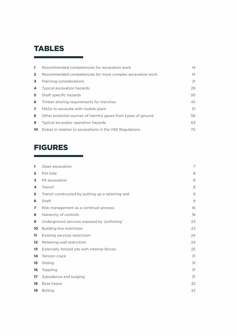
TABLES
1 Recommended competencies for excavation work 14
2 Recommended competencies for more complex excavation work 14
3 Planning considerations 21
4 Typical excavation hazards 29
5 Shaft specifi c hazards 30
6 Timber shoring requirements for trenches 45
7 MADs to excavate with mobile plant 51
8 Other potential sources of harmful gases from types of ground 56
9 Typical excavator operation hazards 63
10 Duties in relation to excavations in the HSE Regulations 70
FIGURES
1 Open excavation 7
2 Pot hole 8
3 Pit excavation 8
4 Trench 8
5 Trench constructed by putting up a retaining wall 9
6 Shaft 9
7 Risk management as a continual process 16
8 Hierarchy of controls 18
9 Underground services exposed by ‘potholing’ 23
10 Building line restriction 23
11 Existing services restriction 24
12 Retaining wall restriction 24
13 Externally fenced site with internal fences 25
14 Tension crack 31
15 Sliding 31
16 Toppling 31
17 Subsidence and bulging 31
18 Base heave 32
19 Boiling 32

20 Benching control 34
21 Battering control 35
22 Combination of benching and battering controls 35
23 ‘Flying’ trench-shoring box 37
24 Hydraulic soldier shoring using soil arching 38
25 Trench-shoring box 39
26 Manhole box 39
27 Trench shield 39
28 Slide-rail or rolling-strut shoring 40
29 Steel sheet piling with internal waling support 41
30 Guide framed steel trench sheeting 41
31 Ground anchors for supporting steel sheet piling 42
32 Hydraulic soldier shoring 43
33 Hydraulic bracing frame with steel trench sheeting 43
34 H-pile shoring with timber lagging 43
35 Soldier sets 44
36 Timber shoring with steel trench sheeting 44
37 Timber shoring requirements for trenches 46
38 A shored excavation designed to carry soil loads only 47
39 A shored excavation designed to carry soil, vehicle and spoil loads 47
40 Spoil placement on eff ective excavation depth 48
41 Scaff olding staircase for a safe and quick evacuation 50
42 Vacuum truck digging a pilot hole 53
43 How an excavator can come in contact with live power lines 55
44 Traditional sump pumps control surface water at the excavation’s base 57
45 Use well point pumping for lowering groundwater by up to 6 m 58
46 Prevent plant operation near excavations 63
47 Wheel stopper restricting plant movement 63
48 Mobile plant operator blind spots 65
49 Safe approach zone for an excavator 66
50 A spotter helping a reversing vehicle 66

GOOD PRACTICE GUIDELINES // EXCAVATION SAFETY
INTRODUCTION
01/
666
IN THIS SECTION:1.1 Scope and application 1.2 What is excavation work?
SECTION 1.0 // INTRODUCTION
7
Excavation failures are particularly dangerous because they may occur quickly, limiting the ability of workers (and in some cases others nearby) to escape, especially if the collapse is extensive.
The speed of an excavation collapse increases
the risk associated with this type of work.
The consequences are signifi cant as the falling
earth can bury or crush any person in its path
resulting in death by suff ocation or internal
crush injuries.
1.1 SCOPE AND APPLICATION
This guideline is for persons conducting a
business or undertaking (PCBUs), workers,
upstream PCBUs, and competent people
involved in excavation work.
All work involving excavations must comply
with the requirements of the Health and
Safety at Work Act 2015 (HSWA) and all
relevant regulations, including the Health
and Safety in Employment Regulations 1995
(the HSE Regulations) and the Health and
Safety at Work (General Risk and Workplace
Management) Regulations 2016 (the GRWM
Regulations).
This guideline does not apply to shafts
associated with mining operations, or
tunnelling operations, which are regulated
under the Health and Safety at Work (Mining
Operations and Quarrying Operations)
Regulations 2016 (the MOQO Regulations).
For more information on the specifi c
regulations relating to excavation work,
see Appendix A: Legal framework.
Some industries have guidelines that deal
with specifi c problems faced in their working
environments, such as the electricity sector
or plant and machinery hire. When deciding
how to do a job safely, make sure to check any
industry specifi c guidance.
1.2 WHAT IS EXCAVATION WORK?
Excavation work generally means work
involving the removal of soil or rock from a
site to form an open face, hole or cavity, using
tools, machinery or explosives.
Excavation work can occur anywhere, including:
> on construction sites
> on business premises
> in public areas.
Excavation work includes:
> open excavations
> potholing
> pit excavations
> trenches and retaining walls
> shafts and drives.
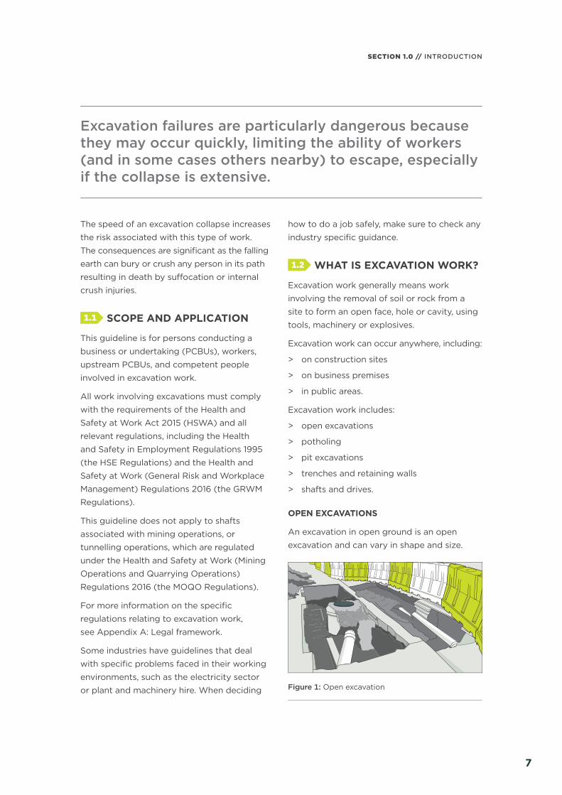
OPEN EXCAVATIONS
An excavation in open ground is an open
excavation and can vary in shape and size.
Figure 1: Open excavation

GOOD PRACTICE GUIDELINES // EXCAVATION SAFETY
88
POTHOLING
Potholing is usually a small excavation or
inspection hole to fi nd underground services.
Water main
Figure 2: Pot hole
PIT EXCAVATIONS
Pit excavations are usually four-sided and
deeper than the narrowest horizontal
dimension at the surface.
Pits are generally excavated to install
manholes, pump stations, or underground
tanks. They are also excavated to construct
pile caps and other types of foundations or
to access or locate existing services.
Figure 3: Pit excavation
TRENCHES AND RETAINING WALLS
A trench is a long narrow excavation which is
deeper than it is wide, and open to the surface
along its length.
Trenches are generally excavated to install
or maintain underground services or to
investigate what is beneath the surface.
Figure 4: Trench
When a retaining wall is built, an open
excavation becomes a trench formed by an
excavated face on one side, and a retaining
wall on the other. Usually workers need to
access this trench to work, for example for
waterproofi ng the retaining wall.

SECTION 1.0 // INTRODUCTION
9
Figure 5: Trench constructed by putting up a retaining wall
SHAFTS AND DRIVES
Sinking a shaft involves constructing a vertical
excavation with access and spoil removal from
the top.
Drives are small openings cut into the sides of
trenches or shafts or elsewhere, for example,
under roads. Cutting a drive is particularly
hazardous as it introduces the risk of trapping
workers with no alternative escape route.
Shafts and drives are often constructed to
provide access or ventilation to a tunnel.
Shallow shafts can be sunk for investigating
or constructing foundations, dewatering, or
providing openings to underground facilities.
Figure 6: Shaft
GOOD PRACTICE GUIDELINES // EXCAVATION SAFETY
ROLES AND RESPONSIBILITIES
02/
101010
IN THIS SECTION:2.1 Person conducting a business
or undertaking 2.2 Workers 2.3 Offi cers 2.4 Other people at the workplace2.5 Competent person

11
SECTION 2.0 // ROLES AND RESPONSIBILITIES
11
HSWA defi nes the roles and responsibilities of diff erent duty holders. These include PCBUs, offi cers, workers and other persons at workplaces.
For more information see WorkSafe’s special
guide Introduction to the Health and Safety
at Work Act 2015, available at www.worksafe.
govt.nz
2.1 PERSON CONDUCTING A BUSINESS OR UNDERTAKING
While a PCBU may be an individual or an
organisation, usually the PCBU will be an
organisation, for example a business entity
such as a company.
All PCBUs must ensure, so far as is reasonably
practicable, the health and safety of workers
and other people are not put at risk by their
work. This is the primary duty of care.
The primary duty of care includes, so far
as is reasonably practicable:
> providing and maintaining:
– a work environment without risks
to health and safety
– safe plant and structures
– safe systems of work
> ensuring safe use, handling and storage
of plant, structures and substances
> providing adequate and accessible welfare
facilities for workers
> providing information, training, instruction
or supervision necessary to protect all
persons from risks to their health and
safety from work
> monitoring workers’ health and conditions
at the workplace to prevent injury or illness.
A PCBU that manages or controls a workplace
must ensure, so far as is reasonably practicable,
the workplace, the means of entering or exiting
the workplace, and anything arising from the
workplace are without health and safety risks
to any person. For example, before leaving the
site unattended for the night, make sure it and
any plant and equipment are safe and secure.
PCBUS WITH OVERLAPPING DUTIES
More than one PCBU can have a duty to the
same matter. Where this happens the PCBUs
have overlapping duties. This might happen in a:
> shared workplace (eg a building site),
where more than one PCBU and its workers
control and infl uence the work on site
> contracting chain, where contractors and
sub-contractors provide services to a
principal contractor and client.
PCBUs that share no contractual relationship
may still share overlapping duties, such as
when they work on the same site.
PCBUs must discharge their overlapping
duties to the extent they have the ability to
infl uence and control the matter, and must,
so far as is reasonably practicable, co-operate,
co-ordinate and consult with others in the
workplace. For example:
> Two individual contractors agree to
co-ordinate their obligations for providing
fi rst aid equipment or personal protective
equipment (PPE).
> A utility company agrees to co-operate
with the PCBU in locating the underground
services before the excavation work starts.
UPSTREAM PCBUs
There are further duties for PCBUs (called
upstream PCBUs) who:
GOOD PRACTICE GUIDELINES // EXCAVATION SAFETY
1212
> design plant, substances or structures
> manufacture plant, substances or structures
> import plant, substances or structures
> supply plant, substances or structures
> install, construct or commission plant
or structures.
Upstream PCBUs infl uence and sometimes
eliminate health and safety risks through,
for example, designing or manufacturing
products that are safe for the end user.
Upstream PCBUs must consider potential
health and safety risks of their products
that could reasonably be expected to be
used at a workplace.
Designers of temporary works or suppliers
of plant used by the PCBU are examples
of upstream PCBUs in excavation work.
WORKER ENGAGEMENT, PARTICIPATION AND REPRESENTATION
PCBUs can ensure a safe workplace more
eff ectively when everyone involved in
the work:
> communicates with each other to identify
hazards and risks
> talks about any health and safety concerns
> works together to fi nd solutions.
PCBUs have two main worker engagement
duties under HSWA to:
> engage with workers on health and safety
matters that aff ect or are likely to aff ect
them, so far as is reasonably practicable
> have practices that give workers
reasonable opportunities to participate
eff ectively in the ongoing improvement
of workplace health and safety.
Both duties involve two-way communication
in a ‘conversation’ about health and safety.
Everyone involved in health and safety must
be able to contribute and have their opinion
considered when decisions are made.
Have deliberate, planned ways to engage
and support participation. Each PCBU can
determine the best way to meet its duties,
depending on workers’ views and needs,
the size of the organisation and the nature
of its risks.
2.2 WORKERS
A worker is an individual who carries out
work in any capacity for a PCBU and includes
employees, contractors, sub-contractors,
apprentices and trainees, and volunteer workers.
Workers’ responsibilities include:
> taking reasonable care of their own
health and safety
> taking reasonable care what they do
(or fail to do) does not cause harm
to any other person
> co-operating with any reasonable health
and safety policy or procedure of the PCBU
> complying, so far as reasonably able, with
any reasonable instruction given by the
PCBU, so the PCBU can comply with the law
> in relation to PPE:
– using or wearing PPE in accordance with
any information, training or reasonable
instruction given by the PCBU
– not intentionally misusing or damaging
the PPE
– telling the PCBU when they become
aware the PPE is damaged or defective,
or when it needs to be cleaned or
decontaminated.
2.3 OFFICERS
An offi cer is a person with a specifi c role in
an organisation or a person with the ability
to exercise signifi cant infl uence over the
management of the business or undertaking.
Organisations can have more than one offi cer.
An offi cer includes, for example, company
directors, and chief executives.
13
SECTION 2.0 // ROLES AND RESPONSIBILITIES
13
Offi cers have a duty to exercise due diligence
to ensure the PCBU complies with their duties
under HSWA. Each offi cer has a duty – it is
not a joint duty.
2.4 OTHER PEOPLE AT THE WORKPLACE
Other people at a workplace must take
reasonable care of their own health and safety
and that of others. However, PCBU’s have
the most infl uence and control over what has
created the risk at the workplace, and have the
primary duty of care to ensure other people’s
health and safety is not at risk from the work.
Other people at a workplace potentially at
risk from work activities include volunteers,
customers, passers-by, visitors, other PCBUs,
or workers of another entity.
Think broadly about the work and make sure,
so far as is reasonably practicable, other
people’s health and safety is not put at risk
from work being done or from anything else
at the workplace.
2.5 COMPETENT PERSON
In this guideline, ‘competent person’ refers to
the temporary works designer, who should
be competent to assess and manage the
risks relevant to the excavation’s depth and
have a working knowledge of this guideline.
A competent person is a person who has
acquired through training, qualifi cation or
experience the knowledge and skills to carry
out a task.
Table 1 and table 2 set out some recommended
competencies for this competent person.
The tables show what level of competence
is appropriate for increasingly complex
excavations.
On sites requiring multiple schemes or
diff erent temporary works disciplines, one
competent person may not have experience
across all the disciplines of temporary works
and may require additional technical support
on site.
Each excavation has its own unique set
of considerations to address during the
design process, some of which may not
be immediately apparent. Therefore, make
an assessment of the appropriate level of
competence for each individual excavation.
Experience and competence can be gained via
diff erent routes and with lesser qualifi cations
(subject to formal assessment of individual
skills) or exemptions made where close
supervision/mentoring is provided by others.
In some workplaces, the same person could
fulfi l a number of roles (such as designer
and supervisor), depending on their level
of competency.
Competency is based on recent knowledge,
training, understanding, and experience with
a wide variety of considerations, some of
which are:
> soil type, weight and strength
> ground water
> sloping ground
> surcharges or vibrations that could
destabilise the excavation, such as vehicles,
buildings or stockpiled materials
> the potential for the excavation to disturb
or damage nearby structures, underground
or overhead services
> safe working methods and construction
methodologies
> availability and capacity of equipment and
temporary works.
Only a competent person should be designing
temporary works. Before producing any fi nal
design documents and safety report, consider:
> the design of the shoring
> any eff ects of the excavation on nearby
structures
> safe work methods
> controls.

GOOD PRACTICE GUIDELINES // EXCAVATION SAFETY
1414
EXCAVATION DEPTH AND TYPE – NORMAL CONDITIONS1
RECOMMENDED COMPETENCY
Up to 1.5 m
> Shored,2 benched, and/or battered (eg shored as per table 6)
> Recent experience in carrying out or supervising excavation work
1.5 m – 3 m
> Flat, open ground, no surcharge
> Shored,2 benched, and/or battered (eg shored as per table 6)
> Recent experience in carrying out or supervising excavation work at these depths
> Technical or trade qualifi cation (eg as a civil engineer or drain layer)
3 m – 6 m
> Flat, open ground, no surcharge
> Shored,2 benched, and/or battered (eg shored as per table 6, waler and brace solutions up to 6 m in depth)
> Technical or trade qualifi cation (eg as a civil engineer or drain layer)
> Recent experience in carrying out or supervising excavation work in similar ground at these depths
> Experienced temporary works designer3 able to interpret the site’s soil information
> Monitoring recommended4
Table 1: Recommended competencies for excavation work
EXCAVATION DEPTH AND TYPE – COMPLEX CONDITIONS NOT COVERED IN TABLE 15
RECOMMENDED COMPETENCY
Up to 3 m
> Shored,2 with benched and/or battered sides
> Experienced temporary works designer3 able to judge whether it is safe
> Monitoring required4
Over 3 m
> Requiring detailed analysis of site, signifi cant structural design analysis and sound engineering judgement
> Shored,2 with benched and/or battered sides
> All sheet piled excavations (cantilevered, propped, or ground anchored), and excavations shored with H-pile shoring and lagging
> Shafts and drives framed with timber or steel with poling boards, lagging or laths. Supported by pre-cast concrete, steel caissons/plates etc
> Experienced temporary works designer3 able to judge whether it is safe
> Monitoring required4
> Can provide producer statements: PS1-design, and PS4-construction review
Table 2: Recommended competencies for more complex excavation work
1 Generally fl at open ground, with little or no surcharge loading, favourable ground conditions, off set from nearby structures and sensitive infrastructure. Groundwater can be controlled with simple methods, such as a sump pump arrangement.
2 Shoring that comes with documents stating what depths or soil pressures it can be used to (eg slide-rail shoring). Alternatively, shoring designed to specifi c soil load profi les (eg trench shields).
3 Through training, qualifi cations or experience, has acquired the knowledge and skills to competently excavate to this depth, for example:
> someone who has industry training and expertise, experience, knowledge and skills to excavate to this excavation’s depth and type
> a Chartered Professional Engineer with experience designing temporary works, holding formal Engineering qualifi cations (eg Civil, Structural or Geotechnical).
4 Can verify the design and carry out monitoring, depending on the risks identifi ed in the risk assessment.5 The conditions may include very weak or sensitive soils, groundwater that requires specialist dewatering, or locations near
structures and sensitive infrastructure. These conditions would result in an elevated risk when constructing the excavation.
MANAGING RISKS
03/
15
IN THIS SECTION:3.1 Identify hazards 3.2 Assess risks 3.3 Control risks 3.4 Review controls

GOOD PRACTICE GUIDELINES // EXCAVATION SAFETY
1616
Risk management involves thinking more broadly about risk, not just spotting work-related hazards. Think about the root cause of any harmful event, the likelihood it will occur, the consequences if it does and the steps to take to eliminate or minimise the risk.
PCBUs must manage all health and safety risks
with excavation work. Remember to consult,
co-operate and co-ordinate with other PCBUs
and to engage with workers.
To manage risks:
> identify hazards that could reasonably
foreseeably create a risk to health
and safety
> eliminate the risk so far as is reasonably
practicable
> if it is not reasonably practicable to
eliminate the risk – minimise the risk
so far as is reasonably practicable
> maintain the implemented controls
so they remain eff ective
> review, and if necessary revise controls
to maintain, so far as is reasonably
practicable, a work environment that
does not have risks to health and safety.
Review and if nessary
revise controls
Maintain controls
and monitor worker health
Eliminate risks and put
controls in place to minimise risks
Identify hazards
Assess hazards and their risks
Figure 7: Risk management as a continual process
3.1 IDENTIFY HAZARDS
The fi rst step in the risk management process
is to identify hazards which could injure or
harm anyone. A good hazard identifi cation
process is the key to risk management.
Identify hazards and controls before the work
starts. It may not be possible to control all
hazards before work starts – so identify the
controls and implement them when required.
For example, consider the hazards to a person:
> falling into an excavation
> being trapped by the collapse of an
excavation
> working in an excavation being struck
by a falling object
> working in an excavation being exposed
to contaminants that take oxygen from
the environment.
To manage the risks, consider all relevant
matters including the:
> nature of the excavation
> nature of the excavation work, including
the range of possible methods of carrying
out the work
> means of entry into and exit from
the excavation.
Complete and monitor hazard identifi cation
regularly to make sure controls are working
and that no new hazards have been introduced.
SECTION 3.0 // MANAGING RISKS
1717
HAZARD IDENTIFICATION METHODS
Identify hazards by:
> physical inspections:
– inspect the workplace and assess
where someone could get injured by
excavation activities
– consider hazards that may be created
by other site users, or if the excavation
activities could create hazards for
others (eg traffi c management)
> task analysis: identify the hazards involved
in each task. Some workplaces use job
safety analysis (JSA) or task analysis
(TA) to do this
> engaging with workers
> process analysis: identify hazards
at each stage of the work plan
> consulting guidance and standards
> hazard and operability analysis (HAZOP)
> accident investigation analysis – identify
hazards and causes of harm from
investigations involving similar types
of work.
3.2 ASSESS RISKS
PCBUs must manage risks that could result
from work. Risks to health and safety arise from
people being exposed to hazards (sources of
harm). Carry out a risk assessment when:
> it is uncertain a hazard may cause injury
or illness
> a work activity involves diff erent hazards,
and the workers involved do not know
how those hazards interact to produce
new or greater risks
> workplace changes may impact on the
eff ectiveness of controls
> new or diff erent risks are associated with
a change in work systems or work location.
PCBUs must eliminate risks so far as is
reasonably practicable. If a risk cannot be
eliminated, it must be minimised so far as is
reasonably practicable.
To decide what is ‘reasonably practicable’,
PCBUs must weigh up all relevant matters.
Those matters include, but are not limited to:
> how likely the hazard or risk is to happen
> what degree of harm the hazard or the
risk might cause
> how much is known about the hazard
or risk and how to eliminate it
> what ways are available to eliminate
or minimise the risk
> what ways are suitable to eliminate
or minimise the risk.
Only consider cost after assessing the
extent of the risk and the available ways
of eliminating or minimising the risk.
There are times when certain work risks must
be dealt with in a specifi ed way. For example,
there are specifi c requirements in regulations
about dealing with the risks arising from
carrying out remote or isolated work or
work dealing with hazardous substances
such as asbestos.
A risk assessment will help to:
> identify which workers or others are at risk
> determine what sources and processes are
causing that risk
> determine the severity of the risk
> identify if and what kind of controls should
be implemented
> check the eff ectiveness of existing controls.
3.3 CONTROL RISKS
Some controls are more eff ective than others.
Controls can be ranked from the highest level
of protection and reliability to the lowest. This
ranking is known as the hierarchy of controls.
Eliminating a risk is the most eff ective control.
PCBUs must always eliminate a risk if this is
reasonably practicable.
If this is not reasonably practicable, PCBUs
must minimise the risk by one or a combination
of the following:

GOOD PRACTICE GUIDELINES // EXCAVATION SAFETY
1818
> Substitution: For example, using an
excavator with a rock breaker rather than
a manual method.
> Isolation: Isolate means preventing contact
or exposure to the risk. For example, using
concrete barriers to separate pedestrians
and mobile plant.
> Engineering controls: For example
benching, battering or shoring the sides
of the excavation to reduce the risk of
ground collapse.
If risk remains, it must be minimised by
implementing administrative controls, so far
as is reasonably practicable, for example by
installing warning signs near the excavation.
Minimise any remaining risk with suitable PPE,
for example hard hats, hearing protectors and
high-visibility vests.
Administrative controls and PPE rely on
human behaviour and supervision. Used on
their own, they tend to be the least eff ective
in minimising risks.
Elimination
Minimisation
Substitution (wholly or partly)
Isolation/preventing contact or exposure to risk
Engineering controls (eg mechanical devices or processes)
Administrative controls (eg methods of work, processes or procedures designed to minimise risk)
Personal protective equipment (PPE)
MOST EFFECTIVE
LEAST EFFECTIVE
Figure 8: Hierarchy of controls
When choosing suitable controls, consider:
> excavating plant: if quantities are large, it
may be eff ective to use diff erent types of
plant for the various materials undergoing
excavation
> stockpiling arrangements: another site may
need to be found to temporarily stockpile
materials
> material placement: evaluate the methods
and plant used for excavating, transporting
and compacting the material
> dewatering equipment
> transporting the excavated material:
– type of plant
– length of haul
– nature of the haul route
– tipping or spreading conditions.
3.4 REVIEW CONTROLS
Regularly review controls on site to make
sure they are still eff ective.
Review, and if necessary revise controls:
> when the control is not eff ective in
controlling the risk (eg if there has been
an incident or near miss)
> before a change at the workplace that
is likely to give rise to a new or diff erent
health and safety risk that the control may
not eff ectively control
> if a new hazard or risk is identifi ed
> if the results of consultation indicate
that a review is necessary
> if a health and safety representative
or committee recommends a review.
Common review methods include workplace
inspections, consultation, testing and analysing
records and data. When reviewing controls,
review the safe system of work or task analysis
and revise it if necessary.
If problems are found, go back through the
risk management steps, review the information
and make further decisions about controls.
PLANNING THE WORK
04/
19
IN THIS SECTION:4.1 Safe system of work 4.2 Utility services 4.3 Nearby buildings or structures 4.4 Securing the work area 4.5 Managing traffi c 4.6 Hazardous conditions 4.7 Confi ned spaces 4.8 Emergency planning
GOOD PRACTICE GUIDELINES // EXCAVATION SAFETY
2020
Planning involves identifying the hazards, assessing risks and deciding suitable controls in consultation with everyone involved in the work including other PCBUs, workers, competent people, and mobile plant operators.
Consider the site factors, hazards and the
unique characteristics of the site. The nature
of the excavation work will aff ect the selection
of an excavation method and a safe system
of work. The ground conditions will have a
signifi cant impact on what excavation method
to select and the controls to use.
Other risks associated with excavation
work, including any connected work such as
construction, must also be controlled so they
do not cause harm to anyone.
4.1 SAFE SYSTEM OF WORK
A safe system of work sets out how a piece of
work or a project will be completed safely and
in compliance with relevant legislation.
Implement a safe system of work before
excavation work starts to make sure the
excavation happens in the right location with
the right plant and equipment on site and with
the right workers with relevant competencies.
Make sure to engage with workers carrying out
the excavation work and their representatives,
and if you are working with other PCBUs,
co-operate, co-ordinate and consult with
them so far as is reasonably practicable.
A safe system of work should include:
> assigning responsibilities
> a task analysis
> consulting a competent person regarding
any temporary works design
> identifying any health and safety hazards
and risks
> carrying out a risk assessment
> describing how you will control any
identifi ed risks
> describing how controls will be
implemented, monitored and reviewed
> accident investigation and reporting
methods
> emergency procedures.
In the event of any reactive excavation
work, establish a safe system of work and
communicate this to workers.
For more information, see:
> Appendix B: Safe system of work
considerations
> Appendix C: Trenching checklist
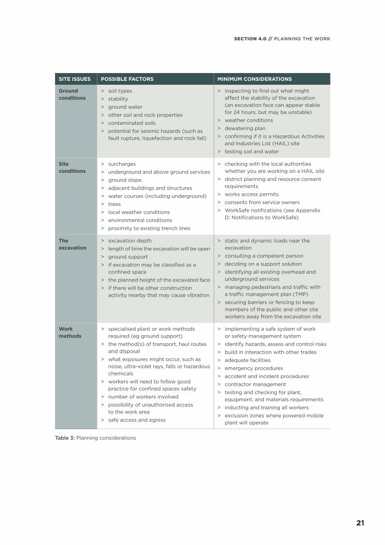
Table 3 provides some information to consider
before starting work. These are the minimum
issues to consider.
21
SECTION 4.0 // PLANNING THE WORK
21
SITE ISSUES POSSIBLE FACTORS MINIMUM CONSIDERATIONS
Ground conditions
> soil types
> stability
> ground water
> other soil and rock properties
> contaminated soils
> potential for seismic hazards (such as fault rupture, liquefaction and rock fall)
> inspecting to fi nd out what might aff ect the stability of the excavation (an excavation face can appear stable for 24 hours, but may be unstable)
> weather conditions
> dewatering plan
> confi rming if it is a Hazardous Activities and Industries List (HAIL) site
> testing soil and water
Site conditions
> surcharges
> underground and above ground services
> ground slope
> adjacent buildings and structures
> water courses (including underground)
> trees
> local weather conditions
> environmental conditions
> proximity to existing trench lines
> checking with the local authorities whether you are working on a HAIL site
> district planning and resource consent requirements
> works access permits
> consents from service owners
> WorkSafe notifi cations (see Appendix D: Notifi cations to WorkSafe)
The excavation
> excavation depth
> length of time the excavation will be open
> ground support
> if excavation may be classifi ed as a confi ned space
> the planned height of the excavated face
> if there will be other construction activity nearby that may cause vibration
> static and dynamic loads near the excavation
> consulting a competent person
> deciding on a support solution
> identifying all existing overhead and underground services
> managing pedestrians and traffi c with a traffi c management plan (TMP)
> securing barriers or fencing to keep members of the public and other site workers away from the excavation site
Work methods
> specialised plant or work methods required (eg ground support)
> the method(s) of transport, haul routes and disposal
> what exposures might occur, such as noise, ultra-violet rays, falls or hazardous chemicals
> workers will need to follow good practice for confi ned spaces safety
> number of workers involved
> possibility of unauthorised access to the work area
> safe access and egress
> implementing a safe system of work or safety management system
> identify hazards, assess and control risks
> build in interaction with other trades
> adequate facilities
> emergency procedures
> accident and incident procedures
> contractor management
> testing and checking for plant, equipment, and materials requirements
> inducting and training all workers
> exclusion zones where powered mobile plant will operate
Table 3: Planning considerations

GOOD PRACTICE GUIDELINES // EXCAVATION SAFETY
2222
4.2 UTILITY SERVICES
Services include gas, water, stormwater,
sewerage, telecommunications and electricity
supply, chemicals, fuel and refrigerant in
pipes or lines. The PCBU must identify and
manage hazards and risks associated with
underground and overhead services in the
planning and design stages. In the fi rst
instance, contact the service owner for
advice prior to works commencing.
For information on the risks of work around
utility service see section 5.7 and WorkSafe’s
Guide for Safety with Underground Services
available at www.worksafe.govt.nz
ESTABLISH WHERE THE SERVICES ARE
Before any excavation takes place workers
should know what is underground and what
is overhead. Consider services present until
it is proven they are not there.
> Liaise with all service owners as there are
often multiple services and multiple owners.
> Some service owners provide on-site
assistance to help identify services; use
this assistance where available.
> Make sure plans and relevant locates
and mark-outs are available, get plans
and mark out the services.
> Accurately trace and mark out underground
services. Drawings and service plans may
be diff erent from what is underground.
> Keep copies of current services plans
on site.
> Use detection equipment that can
detect services. There may be a need
to use multiple types.
> Knowledge about what energy sources
the services actually carry is essential.
Service markings and colours can vary
from current national standards and the
service owner should be able to provide
specifi c information.
> Check service depths as they may vary
from the plan (eg the ground cover may
have been altered since the service was
laid). Pothole to determine service location
and depth.
> Make sure mobile plant access and
egress is safe by checking the proximity
of overhead services and the ground
strength for access routes (eg check for
underground drainage pipes, service ducts,
soak wells, and storage tanks).
HAVE PROCESSES IN PLACE
> Check workers are competent to
complete the tasks. This will include
giving a briefi ng and assessing that plant,
equipment (including safety and protective
equipment), tools, and procedures are fi t-
for-purpose.
> Workers should be supervised to make
sure they carry out the work safely.
> Identify where consents and permits
are required for closer work activities.
This includes:
– liaising with service owners
– sourcing the service owner’s web
information and resources
– understanding permit conditions
– making sure workers understand
what they can and cannot do
– supervising and monitoring
conformance.
> Update the service plan arrangements
with the service owners.
> Reporting, emergency, and response
procedures need to be in place for all
identifi ed risks and hazards.
> Put processes in place for reporting
incidents, damage, and defects.
> Plan for emergency situations where there
is incomplete information about services.
> Develop response plans for workers and
others safety in the event of a service strike.

23
SECTION 4.0 // PLANNING THE WORK
23
WHAT WORK METHODS WILL YOU USE?
> Is the work in proximity to overhead
services?
> Will you expose underground services?
> How will you work with the service owner
and get permission? This may be required
to approach services using hand-held
mechanical tools, or mechanical methods,
and to backfi ll the excavation.
> How will you provide underground service
plans and related information to other
parties, such as other PCBUs and workers
operating mobile plant?
> Will you be backfi lling?
Figure 9: Underground services exposed by ‘potholing’
4.3 NEARBY BUILDINGS OR STRUCTURES
Excavation work may seriously aff ect the
stability of any structure near the excavation.
This may lead to structural failure, or ground
collapse depending on the site’s ground
conditions.
Consider the excavation’s zone of infl uence
on the stability of any nearby structure and
make sure the excavation does not remove
any nearby structure’s ground support.
The zone is normally at an angle from the
base of the excavated face to the surface.
The zone’s angle will depend upon site-specifi c
factors, for example soil strength and density.
Local regulations or resource consent
conditions may also stipulate other controls
for excavating near existing structures.
A competent person should:
> assess any excavation near or below
the footing of any structure, including
retaining walls
> determine if any supports to brace the
structure are required.
Make sure other structures near the excavation
site are not adversely aff ected by vibration or
concussion during the work. If hospitals and
other buildings with equipment sensitive to
shock and vibration are nearby, consider the
need for special precautions.
The zone of infl uence’s angle will depend
upon site-specifi c factors, for example soil
strength and density.
The fi gures below show examples of nearby
structures and services that may restrict the
excavation.
Building foundations
Figure 10: Building line restriction

GOOD PRACTICE GUIDELINES // EXCAVATION SAFETY
2424
Existing trench
Figure 11: Existing services restriction
Retaining wall
Figure 12: Retaining wall restriction
4.4 SECURING THE WORK AREA
Site security should consider all risks to
workers and others. Establish the work
activity’s boundary before securing the work
area. Each work activity may be smaller than
the whole workplace, so as each work activity
moves its boundary moves with it. As the
work boundary moves, so far as is reasonably
practicable, minimise risk to workers and
others outside the work activity.
Other people near the work have a responsibility
to take reasonable care that their actions
(or lack of action) do not put themselves or
others at risk. They must also comply with
any reasonable instruction given by the
PCBU, as far as they are reasonably able to.
For example, a long trench line operation
secures each work activity’s boundary
using movable security arrangements
as the excavation work progresses.
When organising site security and site
access, consider:
> warning or hazard signs
> supervising authorised visitors
> the risk of unauthorised access occurring
(consider schools, parks, shops or other
public places, or amenities and events
nearby)
> pedestrians and other members of public
> other workers and mobile plant on site
> vehicle traffi c control within and near
the excavation
> delivery points, including vehicle access
and egress
> immobilising/locking vehicles
> assessing plant movement to avoid risks
to other moving plant or vehicles outside
the site’s perimeter
> control and storage of any contaminated
materials from the excavation
> safe and secure storage of materials
(eg hazardous substances)
> control of energy sources (eg temporary
mains service boxes, fuel storage)
> suitably designed and constructed physical
barriers (eg safety fences, lockable gates,
or covers).

25
SECTION 4.0 // PLANNING THE WORK
25
Figure 13: Externally fenced site with internal fences
Safety fences prevent people from gaining access into hazardous areas. Guard any excavations
to which the public has or might gain access. Fence off the area even during times when workers
are not present on site.
Any safety fence should comply with the minimum requirements of NZTA’s Code of Practice
for Temporary Traffi c Management available at www.nzta.govt.nz
HSE Regulation 25 requires any readily accessible excavation likely to collect or retain water
to a dangerous depth to be, so far as is reasonably practicable:
> covered or fenced, when no worker is immediately nearby to prevent access; and
> covered, fenced, or fi lled at the completion of the work.
4.5 MANAGING TRAFFIC
Manage traffi c, including all road users while the work takes place with a temporary traffi c
management plan (TMP). All work on a road or work that aff ects the normal operating condition
of a road must have an approved TMP.
If excavations are to take place on or near a road or transport corridor, obtain approval from
the Road Controlling Authority, which is often the local authority or NZTA.
The TMP should show how the excavation will be protected so work can go ahead safely for
workers and others. The TMP should show how traffi c (including cyclists and pedestrians) will
negotiate the site, for example what lanes will be closed by the work, and how.
If the site will be unattended, provide a separate TMP also covering the protection of any
excavations by backfi lling, plating, or fencing. Where work is located on roads controlled by a local
authority, check with the local authority as to what is required for appropriate traffi c management.
For more information refer to NZTA’s Code of Practice for Temporary Traffi c Management
available at www.nzta.govt.nz

GOOD PRACTICE GUIDELINES // EXCAVATION SAFETY
2626
SEPARATING TRAFFIC
Separate the route used for hauling spoil
from the one used by workers. If it is not
possible to separate the traffi c, forbid worker
movement while spoil or plant is being
moved, and vice versa.
Unless the excavation is so shallow those
outside can see and talk easily to those at the
face, provide an eff ective signalling system
and interlocks that prevent winding gear
from operating while personnel are moving.
When mechanical haulage is used in small
drives or manholes, excavate refuges into
the side of the drive to provide shelter from
passing traffi c.
The refuges should be a least 1.2 m deep by
1 m wide by 2 m high (or the height of the
drive if it is less than 2 m) and spaced not
more than 18 m apart. They should all be
on the same side of the drive.
4.6 HAZARDOUS CONDITIONS
Planning considerations should include:
> fi nding out about the current use and
ground history of the work site before
assessing any risk
> investigating and testing if a dangerous
atmosphere will be present or is likely
to be present
> determining if any live services, proximate
water courses, or isolation failures could
cause sudden fl ooding of the excavation
> changes in conditions during work
(ie disturbing sediment)
> the geology (ie peat soils, methane
released from soils).
LOCAL AUTHORITY PLANNING REQUIREMENTS
It is important to obtain the necessary resource
consents before work starts. Check your local
authority’s district plan to fi nd out if resource
consents are necessary.
Contact your regional council to check
whether you are working on a HAIL6 site and
to make sure you comply with the Resource
Management (National Environmental
Standard for Assessing and Managing
Contaminants in Soil to Protect Human Health)
Regulations 2011 (NES)7 before excavating.
For more information refer to section 5.10.
4.7 CONFINED SPACES
The hazard identifi cation and risk assessment
can identify levels of risk that will deem the
excavation a confi ned space under certain
conditions.
A confi ned space is an enclosed or partially
enclosed space, not intended or designed
primarily for human occupancy, where there
is a risk of one or more of the following:
> an oxygen concentration outside the safe
oxygen range
> a concentration of airborne contaminant
that may cause impairment, loss of
consciousness or asphyxiation
> a concentration of fl ammable airborne
contaminant that may cause injury from
fi re or explosion
> engulfment in a stored free fl owing solid
or a rising level of liquid that may cause
suff ocation or drowning.
If the excavation’s characteristics meet the
defi ned criteria refer to AS 2865 Confi ned spaces
to fi nd out the appropriate work methods,
risk management, and emergency planning.
6 The Hazardous Industries and Activity List is available at www.mfe.govt.nz7 The NES is available at www.mfe.govt.nz

27
SECTION 4.0 // PLANNING THE WORK
27
If an excavation is a confi ned space, undertake
pre-entry planning. Make sure:
> workers are trained in confi ned space
entry and enough workers are available
> entry requires a completed permit
for entry
> pre-entry tasks are established and
understood by all
> the atmosphere is tested before entry
and continuously monitored during
entry, if necessary
> ventilation is installed and adequate
where deemed necessary
> an emergency plan is established,
planned and workable
> suitable standby person/s are present,
trained and aware of their specifi c tasks
in the event of an emergency
> communication is established with the
standby person/s
> all equipment is suitable and operational,
within current inspection dates, and
used by workers trained in the use
of the equipment.
The natural reaction to immediately enter
and try to rescue a person often leads to
the serious injury or death of the would-be
rescuer/s. A suitably trained and competent
standby person should be present to
communicate and oversee the work being
conducted. They will co-ordinate the response
to any emergency. Emergency response
planning should follow the requirements
of AS 2865.
For more information about confi ned spaces,
see WorkSafe’s fact sheet Confi ned Spaces:
Planning Entry and Working Safely in a
Confi ned Space, available at www.worksafe.
govt.nz
4.8 EMERGENCY PLANNING
The PCBU must have an emergency plan
for the workplace. It needs to be maintained
to remain eff ective.
The PCBU must make sure the emergency
plan deals with unexpected incidents such as
ground slips, fl ooding, gas leaks, and how to
rescue workers from an excavation. Planning
must determine all the potential emergency
conditions. A suitable response must be
developed for each credible emergency.
To ensure a co-ordinated response to an
emergency, the excavation emergency plan
should be incorporated into any broader
construction project emergency plan.
GRWM Regulation 14 requires that the
PCBU prepare, maintain, and implement an
emergency plan.
More information about emergency planning
requirements is available on www.worksafe.
govt.nz
GOOD PRACTICE GUIDELINES // EXCAVATION SAFETY
CONTROLLING EXCAVATION RISKS
05/
2828
IN THIS SECTION:5.1 Ground collapse 5.2 Prevent ground collapse 5.3 Benching and battering 5.4 Shoring 5.5 Excavated material and
loads near excavations 5.6 Prevent falls 5.7 Safe access and egress
5.8 Manual work 5.9 Overhead and underground
services 5.10 Atmospheric contaminants5.11 Ground and surface water5.12 Contaminated soils and
groundwater5.13 Using explosives

SECTION 5.0 // CONTROLLING EXCAVATION RISKS
2929
This section outlines common risks that PCBUs should manage throughout any excavation.
First try and eliminate the risks but if that is not reasonably practicable, then minimise them,
so far as is reasonably practicable. A combination of controls may need to be used. Make sure
controls prevent anyone being harmed, so far as is reasonably practicable. They must translate
into practical standards and expectations, roles, responsibilities, and processes that are relevant
for everyone in the supply chain.
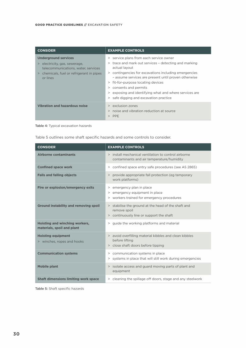
Table 4 outlines some excavation hazards and some controls to consider.
CONSIDER EXAMPLE CONTROLS
Excavation hazards
> placement of excavated materials, plant or other loads
> infl uence on any nearby structure
> previous disturbance of the ground
> external actions causing instability
> presence of or possible inrush of water or other liquid
> hazardous substances (eg those present in the soil)
> identify safe and secure places for excavated materials, plant and other equipment
> geotechnical information and competent person’s input for stability and best method for support
> processes for dewatering in place
> assess hazardous substances and contaminated soil
Falls and falling objects
> falls from one level to another
> earth or rock falls
> edge protection in place
> safe access and egress
> catch platforms
Hazardous atmosphere in an excavation > gas and fumes monitoring
> respirators – fi tted and maintained correctly
Manual handling tasks > using lifting devices (eg hiabs, cranes, trolleys)
> manual handling training
Natural hazards and weather > geotechnical site assessment
> inspecting to fi nd out what might aff ect the stability of the excavation (an excavation face can appear stable for 24 hours, but may be unstable)
Overhead services > identifi cation and inclusion in safe system of work
> minimum approach distances for mobile plant and work activity from overhead lines
> minimum approach distances for excavation and earthworks from towers and support structures
> consents or permits
> applying required safety measures
Site safety
> insuffi cient natural lighting
> traffi c management plan
> site security
> safety fencing and signage
> provide suitable artifi cial lighting
GOOD PRACTICE GUIDELINES // EXCAVATION SAFETY
3030
CONSIDER EXAMPLE CONTROLS
Underground services
> electricity, gas, sewerage, telecommunications, water, services
> chemicals, fuel or refrigerant in pipes or lines
> service plans from each service owner
> trace and mark out services – detecting and marking actual layout
> contingencies for excavations including emergencies – assume services are present until proven otherwise
> fi t-for-purpose locating devices
> consents and permits
> exposing and identifying what and where services are
> safe digging and excavation practice
Vibration and hazardous noise > exclusion zones
> noise and vibration reduction at source
> PPE
Table 4: Typical excavation hazards
Table 5 outlines some shaft specifi c hazards and some controls to consider.
CONSIDER EXAMPLE CONTROLS
Airborne contaminants > install mechanical ventilation to control airborne contaminants and air temperature/humidity
Confi ned space work > confi ned space entry safe procedures (see AS 2865)
Falls and falling objects > provide appropriate fall protection (eg temporary work platforms)
Fire or explosion/emergency exits > emergency plan in place
> emergency equipment in place
> workers trained for emergency procedures
Ground instability and removing spoil > stabilise the ground at the head of the shaft and remove spoil
> continuously line or support the shaft
Hoisting and winching workers, materials, spoil and plant
> guide the working platforms and material
Hoisting equipment
> winches, ropes and hooks
> avoid overfi lling material kibbles and clean kibbles before lifting
> close shaft doors before tipping
Communication systems > communication systems in place
> systems in place that will still work during emergencies
Mobile plant > isolate access and guard moving parts of plant and equipment
Shaft dimensions limiting work space > cleaning the spillage off doors, stage and any steelwork
Table 5: Shaft specifi c hazards

SECTION 5.0 // CONTROLLING EXCAVATION RISKS
3131
5.1 GROUND COLLAPSE
Ground collapse is one of the main risks of
excavation work.
All excavations, no matter what depth, can
be risky. Ground collapse can occur quickly
and without warning, giving a worker virtually
no time to escape, especially if the collapse
is extensive. A buried worker is likely to die
of suff ocation before help arrives (either the
head is buried, or the chest is so restricted
by the ground’s weight the worker cannot
breathe).
Some types of ground collapse are:
Figure 14: Tension crack
Tension cracks usually form at a horizontal
distance of 0.5 to 0.75 times the depth of
the excavation, measured from the top of the
vertical face of the excavation.
Figure 15: Sliding
Sliding (or sloughing) may occur as a result
of tension cracks.
Figure 16: Toppling
In addition to sliding, tension cracks can cause
toppling. Toppling occurs when a face shears
along the tension crack line and topples into
the excavation.
Figure 17: Subsidence and bulging
An unsupported excavation can create an
unbalanced stress in the soil which, in turn,
causes subsidence at the surface and bulging
of the face. If uncorrected, this condition can
cause face failure and trap workers in the
excavation.
GOOD PRACTICE GUIDELINES // EXCAVATION SAFETY
3232
Soilweight
Heave
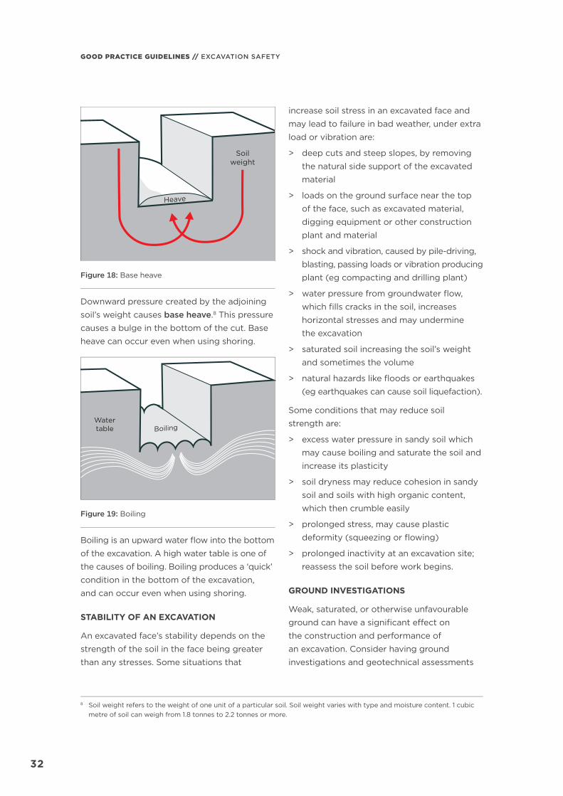
Figure 18: Base heave
Downward pressure created by the adjoining
soil’s weight causes base heave.8 This pressure
causes a bulge in the bottom of the cut. Base
heave can occur even when using shoring.
Watertable Boiling
Figure 19: Boiling
Boiling is an upward water fl ow into the bottom
of the excavation. A high water table is one of
the causes of boiling. Boiling produces a ‘quick’
condition in the bottom of the excavation,
and can occur even when using shoring.
STABILITY OF AN EXCAVATION
An excavated face’s stability depends on the
strength of the soil in the face being greater
than any stresses. Some situations that
increase soil stress in an excavated face and
may lead to failure in bad weather, under extra
load or vibration are:
> deep cuts and steep slopes, by removing
the natural side support of the excavated
material
> loads on the ground surface near the top
of the face, such as excavated material,
digging equipment or other construction
plant and material
> shock and vibration, caused by pile-driving,
blasting, passing loads or vibration producing
plant (eg compacting and drilling plant)
> water pressure from groundwater fl ow,
which fi lls cracks in the soil, increases
horizontal stresses and may undermine
the excavation
> saturated soil increasing the soil’s weight
and sometimes the volume
> natural hazards like fl oods or earthquakes
(eg earthquakes can cause soil liquefaction).
Some conditions that may reduce soil
strength are:
> excess water pressure in sandy soil which
may cause boiling and saturate the soil and
increase its plasticity
> soil dryness may reduce cohesion in sandy
soil and soils with high organic content,
which then crumble easily
> prolonged stress, may cause plastic
deformity (squeezing or fl owing)
> prolonged inactivity at an excavation site;
reassess the soil before work begins.
GROUND INVESTIGATIONS
Weak, saturated, or otherwise unfavourable
ground can have a signifi cant eff ect on
the construction and performance of
an excavation. Consider having ground
investigations and geotechnical assessments
8 Soil weight refers to the weight of one unit of a particular soil. Soil weight varies with type and moisture content. 1 cubic metre of soil can weigh from 1.8 tonnes to 2.2 tonnes or more.
SECTION 5.0 // CONTROLLING EXCAVATION RISKS
3333
for excavations that are complex or may
aff ect nearby structures or harm workers and
others nearby. The ground investigation and
geotechnical assessments should include:
> advice on the suitability of diff erent sites
or distinct areas of a site for placing
structures or services
> suitable and economic design of both
temporary and permanent works
> a method to identify and evaluate possible
problems in constructing temporary and
permanent works
> a process to reduce the risk of unforeseen
ground conditions. This will decrease
the need for changes in design and
construction methods.
5.2 PREVENT GROUND COLLAPSE
If excavation work is planned without shoring,
the continuing safety of the excavation will
depend on the conditions arising during
construction. If the conditions during
construction are not as expected, or if
conditions change during the course of the
work (eg diff erent soils, heavy rain/fl ooding)
take immediate action to protect workers,
other people and property.
Excavations shallower than 1.5 m have been
known to collapse. If a worker is in the
excavation and bending over or crouching
down at the time of the collapse, he or she
may suff er serious injury. PCBUs must consider
the risks associated with these excavations
and determine if special precautions or work
methods are necessary, for example shoring.
MANAGING THE RISK
There are three main types of controls to
prevent ground collapse. Make sure to use one
or more of the following controls to support all
sides of the excavation:
> Benching and battering is the horizontal
stepping or sloping of the face, side, or wall
of an excavation.
> Shoring prevents collapse by maintaining
positive pressure on the sides of the
excavation, protecting workers.
> Shields do not ensure ground stability but
protect workers from ground collapse, by
preventing the collapsing material falling
onto them.
No matter how deep an excavation is, if there
is a risk of collapse, put controls in place to
prevent this. Involve a competent person
when selecting what ground collapse controls
to apply.
A combination of controls may be most
eff ective, depending on the work environment
and characteristics of the excavated material.
In built-up areas or streets the excavation
may have to be fully or partly sheeted, or
supported to prevent collapse due to localised
vehicle movement and vibration.
If shoring is impracticable or unreasonable,
make sure a competent person certifi es
any other safety precautions put in place as
adequate. The competent person’s advice
should state the time period it applies to,
and may be subject to a condition that
specifi ed natural occurrences may create
a risk of collapse.
A report from a competent person can provide
information on the stability and safety of an
excavation. The report should include:
> details of the soil conditions
> any shoring or excavation support
requirements
> dewatering requirements
> any longer term eff ects on stability
and safety of the excavation.
GOOD PRACTICE GUIDELINES // EXCAVATION SAFETY
3434
HSE Regulation 24 requires any excavated face more than 1.5 m high to be shored, so far as is
reasonably practicable, unless:
> the face is cut back to a safe slope, or
> the material in the face is of proven good standing quality under all reasonably foreseeable
conditions of work and weather, or
> by reason of the nature of the work and the position of any worker in the vicinity, there is
no danger to any worker, or
> shoring is impracticable or unreasonable and other precautions have been taken to make
the face as safe as possible in the circumstances.
REGULAR INSPECTION
The condition of soil surrounding excavations can change quickly when the soil dries out, the
water table changes or water saturates the soil. A competent person should frequently check
the soil condition and the state of shoring, benching, battering, and excavated faces for signs
of earth fretting, slipping, slumping, or ground swelling. If necessary, the PCBU should repair
the excavation or strengthen the shoring from above before allowing work below ground
to continue.
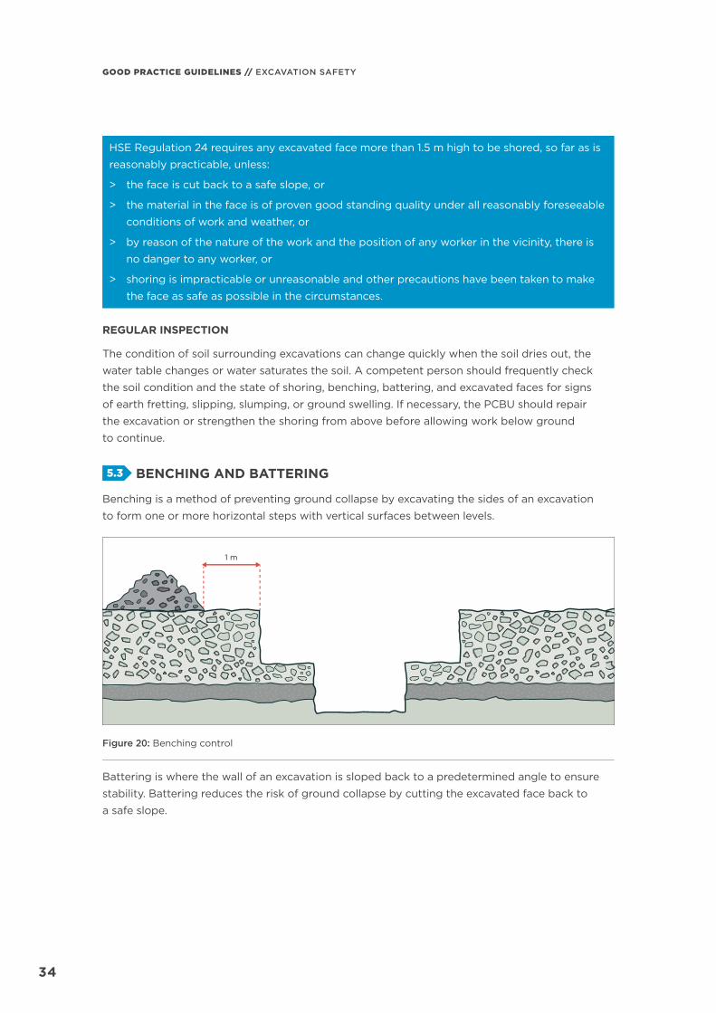
5.3 BENCHING AND BATTERING
Benching is a method of preventing ground collapse by excavating the sides of an excavation
to form one or more horizontal steps with vertical surfaces between levels.
1 m
Figure 20: Benching control
Battering is where the wall of an excavation is sloped back to a predetermined angle to ensure
stability. Battering reduces the risk of ground collapse by cutting the excavated face back to
a safe slope.

SECTION 5.0 // CONTROLLING EXCAVATION RISKS
3535
1 m 1 m
Figure 21: Battering control
Sometimes it may be appropriate to use a combination of benching and battering on an excavation.
1 m
Figure 22: Combination of benching and battering controls
Benching and battering of excavation walls can minimise the risk of soil or rock slipping onto
the excavation.
A competent person should design controls considering:
> soil type
> soil moisture content
> planned height of the excavated face
> any surcharge loads acting on the excavated face.
It is not necessary to bench or batter excavated faces which a competent person determines
are in stable rock, or has assessed there is no risk of collapse. If benching or battering excavated
walls, do not exceed the soil type’s angle of repose unless designed by a competent person and
certifi ed in writing.
GOOD PRACTICE GUIDELINES // EXCAVATION SAFETY
3636
Benches should be wide enough to stabilise
the slope to prevent spoil falling into the
excavation. They should also be sloped to
reduce the possibility of water scouring.
When designing the face, slopes and widths of
benches, consider any earthmoving machinery
that may be used and any related haul routes.
5.4 SHORING
Shoring provides support to excavated faces
to prevent soil moving and ground collapsing.
If the ground is not self-supporting, and
benching or battering is not suitable, use
shoring to manage the risk of a person being
buried or trapped during excavation work.
When choosing shoring as a control use
certifi ed proprietary or non-proprietary
systems, within their rated load capacity
limits according to manufacturer or supplier
instructions.
Involve a competent person when selecting
what shoring to use. This is to make sure
the shoring is fi t for purpose. Otherwise, a
competent person should design the shoring
for the specifi c workplace conditions.
If risks remain for those installing shoring,
put other suitable controls in place to ensure
the health and safety of workers entering
the excavation.
Shore the excavated face as the excavation
work progresses. If using mobile plant, assess
the risk to fi nd out if any part of the excavation
may be left unsupported.
As part of your safe system of work, make
sure workers do not enter any unprotected
part of the excavation. If the shoring is being
progressively installed workers should not
work ahead of the shoring.
Shoring should extend above ground level if
practicable, or at least to ground level if that
is not practicable, for example where covers
may need to be placed over the excavation
at night. If the shoring does not extend to
at least ground level, bench or batter the
excavation and make sure the shoring can
take the surcharge load.
HSE Regulation 24 requires that any
shoring, so far as is reasonably practicable:
> consists of materials that are suitable
for the purpose for which they are to
be used, of sound quality, and adequate
in strength for the particular use
> has bracings, jacks, and struts securely
held to prevent accidental displacement,
and packings and wedges that are held
by nails or spikes
> be placed properly by an experienced
person under competent supervision
> not be altered, dismantled, or interfered
with except on the instructions of the
employer or a representative of the
employer.
FLYING SHORING
When using shoring, it may be possible to
excavate below the base of the shoring, that
is: ‘fl ying shoring’.
To do this, excavate to a maximum depth of
600 mm below the base of the shoring, if:
> the shoring is designed to resist the
forces calculated for the full depth of the
excavation, and
> there are no indications, while the excavation
is open, of instability below the bottom
of the shoring.
SECTION 5.0 // CONTROLLING EXCAVATION RISKS
3737
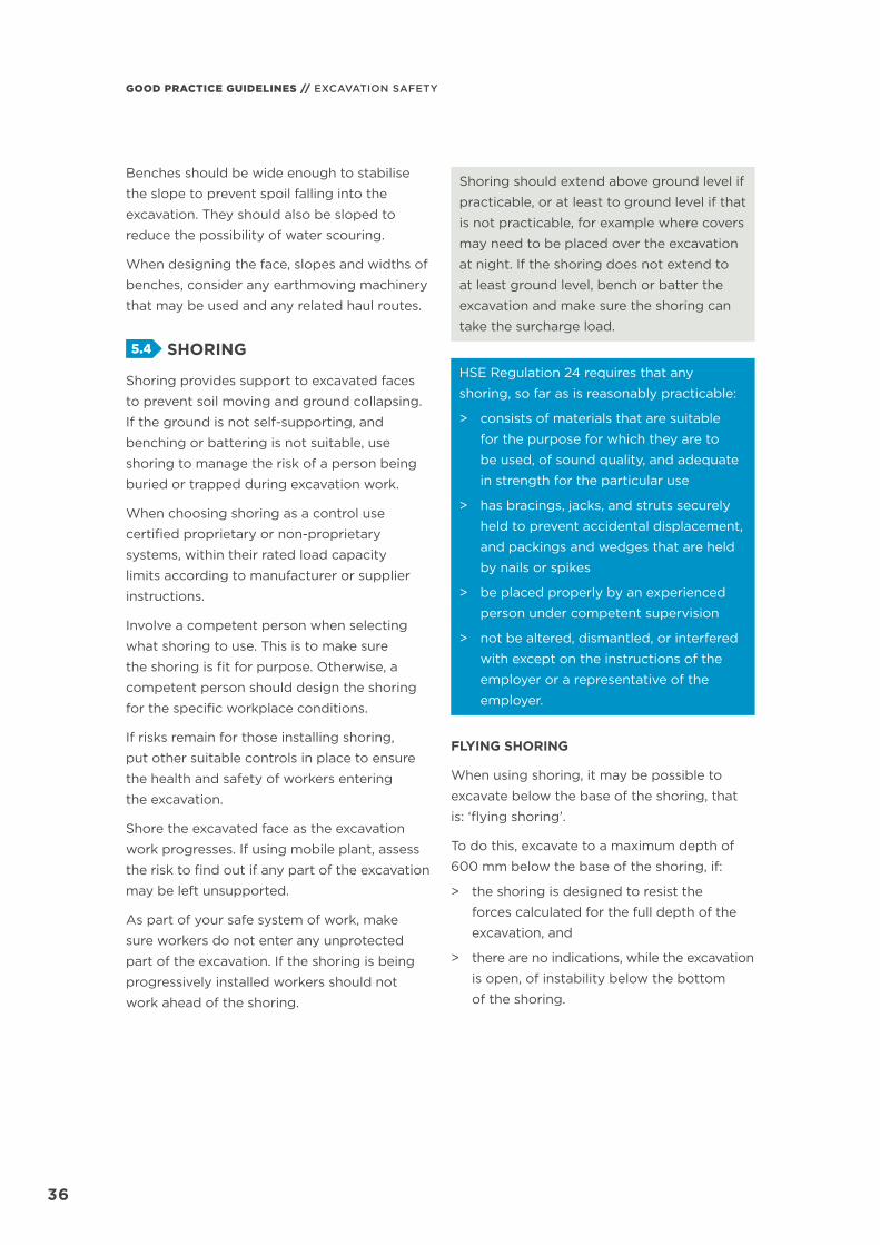
Control the risk of ground collapse and
carefully visually inspect for any eff ects of:
> bulging
> base heave
> boiling
> surcharge loading
> vibration and other forces.
Adjustablemechanicalstruts Top box
Base box
Figure 23: ‘Flying’ trench-shoring box
SHORING THAT USES SOIL ARCHING
Shoring that slightly compresses soil without
allowing the soil to move outward can produce
an arching eff ect in the soil. This is ‘soil arching’.
Soil arching allows excavated walls shored
with struts to stand even with no sheeting or
lagging between the struts, without the soil
behind fl owing out.
Soil arching does not reduce the total soil load,
but distributes it to the shoring and away from
the excavated face.
The ability for shoring to use soil arching
depends on the consistency of the soil. Both
cohesive and non-cohesive soils will experience
soil arching to some extent. Generally for
soil arching to work there has to be a small
amount of soil movement, but soils lacking
cohesion are usually not good candidates.
Shoring that uses soil arching is generally only
suitable for excavations less than 2 m deep
and where each section of the excavation is
open for less than one week.
Make sure to follow the manufacturer’s or
supplier’s advice on spacing requirements and
recommended preload pressures for shoring;
however the closer the shoring is, the better
soil arching works.
When using shoring, make sure:
> the soil is good enough for the excavation
to stand when excavated
> to install support as soon as practicable
> to achieve at least minimum pressure when
pumping out hydraulic support and to
maintain it
> to use a minimum of three sets of support
with a maximum spacing of 1.5 m
> to minimise the length of time the
excavation is open.
Some ravelling, or soil falling off the excavated
face between the support may occur but this
will not compromise the shoring. Use backing
boards or lagging to eliminate or minimise
ravelling.

GOOD PRACTICE GUIDELINES // EXCAVATION SAFETY
3838
Soil Movement
Soil Movement
Arching
Arching
End oftrench Strut
For soil to failit must move
around thestrut
Figure 24: Hydraulic soldier shoring using soil arching
REMOVING SHORING
Remove shoring and all supports in a way that protects workers from ground collapse, structural
collapse, or being struck. To keep workers safe, temporary structural members may need to be
installed before any removal begins.
When removing shoring, take apart and extract it in reverse order to its installation. Workers
should not work outside the protection of the shoring. No part of a shoring system should be
removed until the excavation is ready for fi nal backfi ll and compaction.
TYPES OF SHORING
Trench-shoring boxes, manhole boxes and trench shields
A trench-shoring box is able to withstand the forces imposed by ground, water, or surcharge
loads. It will protect workers within it, as well as prevent ground collapse. This is achieved by
‘digging and pushing’ the box into the ground as the excavation proceeds, maintaining positive
pressure on the excavated faces at all times.

SECTION 5.0 // CONTROLLING EXCAVATION RISKS
3939
Adjustablemechanicalstruts Top box
Base box
Figure 25: Trench-shoring box
Manhole boxes are a subset of trench-shoring
boxes. They are designed and constructed using
the same methods and materials as trench-
shoring boxes. Most manhole boxes are installed
using the ‘dig and drop’ method. If ground
conditions are poor enough that the dig and
drop method is not practical, consider digging
and pushing manhole box shoring, corner-slide
rails or hydraulic brace and sheet systems.
Adjustable mechanicalstruts
Base box with partially open ends for pipe entry and exit
Figure 26: Manhole box
Trench shields are diff erent to trench-shoring
boxes as they are only designed to protect
workers if a collapse occurs. Trench shields
are designed to be installed using the dig
and drop method and dragged along as
work progresses.
Steel Plates
Strut
Figure 27: Trench shield
Using trench-shoring boxes and shields
correctly makes it safe for workers entering
the excavation, while protecting any nearby
services or structures. Make sure enough
trench-shoring boxes and shields are used to
suitably protect workers, as the ends remain
open, exposing workers near the ends to
falling material. Workers should not work
near each end. The length of pipes or services
to install usually determines the number of
trench-shoring boxes to use.

GOOD PRACTICE GUIDELINES // EXCAVATION SAFETY
4040
Use trench-shoring boxes and shields where
access is available for an excavator or backhoe
to install or extract it from a trench. They are
normally not suitable where access is diffi cult
and ground conditions prevent the use of
lifting equipment.
Trench-shoring boxes and trench shields should
not exceed their maximum designed load. To
reduce the load and depth of the excavation,
use benching and battering practices.
Suitably maintain trench-shoring boxes and
shields or they may fail unexpectedly, particularly
if they are damaged. Follow the manufacturer’s
or supplier’s instructions for installing, using,
removing, and maintaining them. Regularly
inspect them for damage and have a competent
person approve any modifi cations.
Follow the manufacturer’s or supplier’s
instructions when storing or transporting
trench-shoring boxes and shields. Heavy-
duty equipment may require disassembly
for transport.
For more information on trench-shoring boxes,
including specifi c soil and surcharge profi les
refer to AS 4744.1: Steel shoring and trench
lining equipment.
Slide-rail or rolling-strut shoring
Slide-rail shoring is diff erent from trench-shoring
boxes and shields, because all parts including
posts, panels, and rolling-strut assemblies move
during the excavation. Slide-rail shoring features
vertical rail posts and panels designed and
manufactured to slide relative to each other to
dig the shoring into the ground. The rolling-strut
allows the struts to move up and down the slide-
rail post during installation.
Slide-rail shoring is available in parallel
confi gurations for trenches or rectangular
confi gurations for deep pit excavations.
Slide-rail shoring may be used as an
alternative to interlocked sheet-pile and H-pile
shoring. Slide-rail shoring is normally eff ective
to depths of up to 9 m.
Evaluate slide-rail shoring alongside other
deep shoring systems, especially sheet-pile
and H-pile systems. All three systems work
best in poor ground conditions such as loose
sands, gravels, and soft cohesive clays.
Install slide-rail shoring as the excavation work
is progressing. Slide-rail shoring is designed so
no void is left in the ground after it is removed.
The rail posts and panels can be raised
simultaneously with the backfi ll operation.
Sliding panels Slide rail
Rolling strut asembly
Figure 28: Slide-rail or rolling-strut shoring
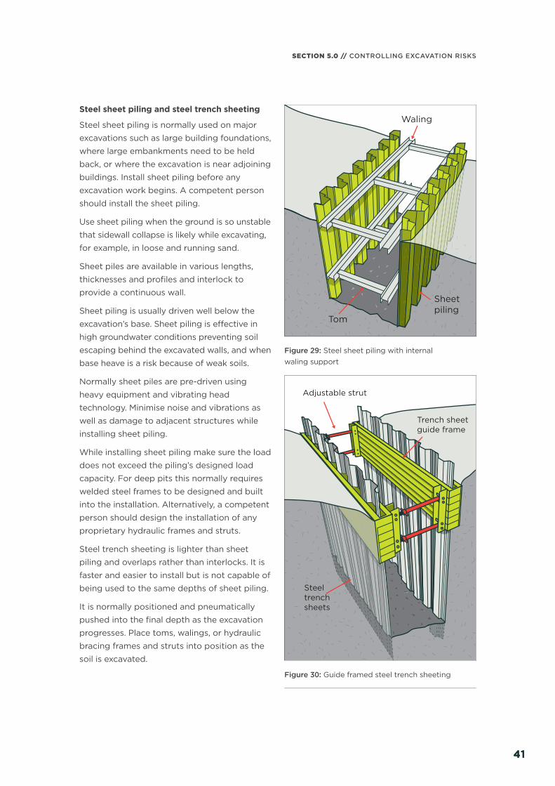
SECTION 5.0 // CONTROLLING EXCAVATION RISKS
4141
Steel sheet piling and steel trench sheeting
Steel sheet piling is normally used on major
excavations such as large building foundations,
where large embankments need to be held
back, or where the excavation is near adjoining
buildings. Install sheet piling before any
excavation work begins. A competent person
should install the sheet piling.
Use sheet piling when the ground is so unstable
that sidewall collapse is likely while excavating,
for example, in loose and running sand.
Sheet piles are available in various lengths,
thicknesses and profi les and interlock to
provide a continuous wall.
Sheet piling is usually driven well below the
excavation’s base. Sheet piling is eff ective in
high groundwater conditions preventing soil
escaping behind the excavated walls, and when
base heave is a risk because of weak soils.
Normally sheet piles are pre-driven using
heavy equipment and vibrating head
technology. Minimise noise and vibrations as
well as damage to adjacent structures while
installing sheet piling.
While installing sheet piling make sure the load
does not exceed the piling’s designed load
capacity. For deep pits this normally requires
welded steel frames to be designed and built
into the installation. Alternatively, a competent
person should design the installation of any
proprietary hydraulic frames and struts.
Steel trench sheeting is lighter than sheet
piling and overlaps rather than interlocks. It is
faster and easier to install but is not capable of
being used to the same depths of sheet piling.
It is normally positioned and pneumatically
pushed into the fi nal depth as the excavation
progresses. Place toms, walings, or hydraulic
bracing frames and struts into position as the
soil is excavated.
Tom
Sheetpiling
Waling
Figure 29: Steel sheet piling with internal waling support
Adjustable strut
Steeltrenchsheets
Trench sheetguide frame
Figure 30: Guide framed steel trench sheeting

GOOD PRACTICE GUIDELINES // EXCAVATION SAFETY
4242
Ground anchors
A ground anchor is a structural element
installed in soil or rock to transfer a tensile
load into the ground. Ground anchors
(sometimes referred to as ‘tie-backs’) alone
do not support an excavation, they form part
of a larger shoring system, typically with steel
sheet piling.
When using ground anchors consider:
> ground conditions
> load cases
> performance criteria
> construction methodology
> construction materials.
Ground anchors may be used:
> in either granular or clay soils
> if the excavation extends through poor
ground conditions
> if sensitive structures are nearby.
Install ground anchors in grout fi lled drill holes.
A competent person should:
> design ground anchors in accordance
with commonly accepted standards,
for example:
– FHWA-IF-99-015 Ground anchors
and anchored systems
– BS EN 1537 Execution of special
geotechnical works – ground anchors
– BS 8081 Code of practice for
grouted anchors
> perform a series of sustained static load
tests on a sample of anchors to confi rm
they have suffi cient load capacity and meet
performance criteria
> always approve any soil removal above
ground anchors.
Consider having the competent person
prepare producer statements:
> PS1 Design
> PS4 Construction review.
Connection to piling
Steel sheet piling
ExcavationsurfaceEExccavvationsurfacee
Ground anchors (soil reinforcement)in compacted ground
Figure 31: Ground anchors for supporting steel sheet piling
Hydraulic support
Hydraulic support comes in confi gurations
from small, lightweight aluminium, glass-
reinforced plastic (GRP) composite or
aluminium soldier sets, to large steel hydraulic
bracing frames and struts.
Except for small soldier sets, or waler and
sheet systems, hydraulic shoring is normally
used with steel trench sheeting or sheet piles.
Consider ground pressures before installing
hydraulic supports. In complex situations,
requiring support other than small soldier
sets or waler and sheet systems, a competent
person should design hydraulic support in
consultation with a geotechnical engineer.
The competent person should design hydraulic
support to resist the expected ground
pressures and potential for collapse.
Properly maintain and use hydraulic support
or it may become unreliable. Frequently
inspect pressure hoses and rams to detect
abrasion, fatigue, or damage such as bent
or notched rams.
When the excavation has been fully supported,
dismantle the hydraulic support to prevent
damage. Inspect, repair if necessary, and
store the hydraulic supports so they are not
damaged before they are used next.

SECTION 5.0 // CONTROLLING EXCAVATION RISKS
4343
For more information on hydraulic shoring
refer to AS 5047: Hydraulic shoring and trench
lining equipment.
SoldierHydraulic strut
Figure 32: Hydraulic soldier shoring
Handling andrestraining point
Corner pin
Hydraulic bracing frameleg
Hangingchain
Valve housingand hose connections
Figure 33: Hydraulic bracing frame with steel trench sheeting
H-pile shoring
H-pile shoring is normally used in large open
excavations or pit excavations. Steel H-piles
are an advanced form of piling installed by
drilling or driving. Timber lagging is normally
used between the H-piles every 1.8 to 3 m. Each
excavation will require a site-specifi c design.
Only use H-pile shoring in ground which has
enough soil arching potential to permit lagging.
The soil should be above the static groundwater
level, or have been dewatered. Lagging does
not extend below the excavation’s base so
do not use H-pile shoring and lagging where
there is potential for base heave or water and
soil fl ows.
Figure 34: H-pile shoring with timber lagging
Soldier sets
Soldier sets are a simple form of support
mostly used in rock, stiff clays and in other soil
types with self-supporting properties capable
of generating soil arching.
Unlike closed sheeting sets, soldier sets only
provide ground support at regular intervals
and do not provide positive ground support
to the whole excavated face.
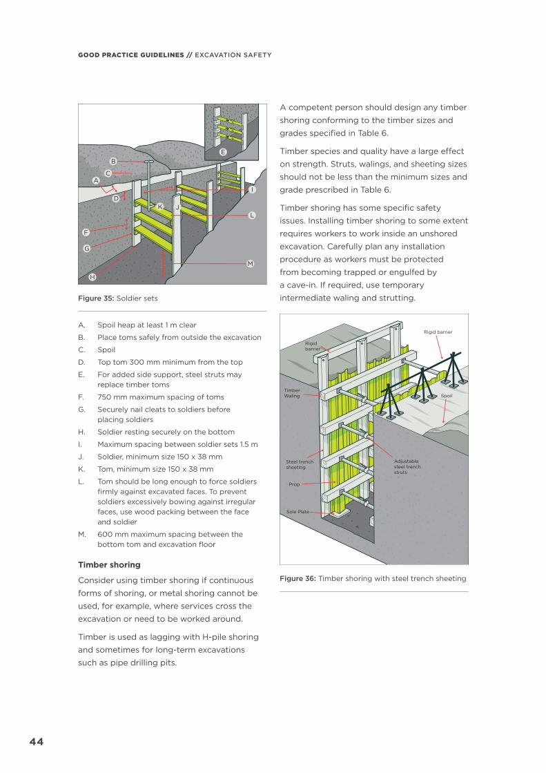
GOOD PRACTICE GUIDELINES // EXCAVATION SAFETY
4444
A
B
C
D
E
F
G
H
I
JKL
M
Figure 35: Soldier sets
A. Spoil heap at least 1 m clear
B. Place toms safely from outside the excavation
C. Spoil
D. Top tom 300 mm minimum from the top
E. For added side support, steel struts may replace timber toms
F. 750 mm maximum spacing of toms
G. Securely nail cleats to soldiers before placing soldiers
H. Soldier resting securely on the bottom
I. Maximum spacing between soldier sets 1.5 m
J. Soldier, minimum size 150 x 38 mm
K. Tom, minimum size 150 x 38 mm
L. Tom should be long enough to force soldiers fi rmly against excavated faces. To prevent soldiers excessively bowing against irregular faces, use wood packing between the face and soldier
M. 600 mm maximum spacing between the bottom tom and excavation fl oor
Timber shoring
Consider using timber shoring if continuous
forms of shoring, or metal shoring cannot be
used, for example, where services cross the
excavation or need to be worked around.
Timber is used as lagging with H-pile shoring
and sometimes for long-term excavations
such as pipe drilling pits.
A competent person should design any timber
shoring conforming to the timber sizes and
grades specifi ed in Table 6.
Timber species and quality have a large eff ect
on strength. Struts, walings, and sheeting sizes
should not be less than the minimum sizes and
grade prescribed in Table 6.
Timber shoring has some specifi c safety
issues. Installing timber shoring to some extent
requires workers to work inside an unshored
excavation. Carefully plan any installation
procedure as workers must be protected
from becoming trapped or engulfed by
a cave-in. If required, use temporary
intermediate waling and strutting.
Spoil
Rigid barrier
Rigid barrier
TimberWaling
Adjustablesteel trenchstruts
Steel trenchsheeting
Prop
Sole Plate
Figure 36: Timber shoring with steel trench sheeting

SECTION 5.0 // CONTROLLING EXCAVATION RISKS
4545
SOIL
C
ON
DIT
ION
STR
EN
CH
D
EP
TH
(m)
TIM
BE
R S
HE
ETI
NG
TIM
BE
R W
ALI
NG
STI
MB
ER
STR
UTS
STE
EL
AD
JUST
AB
LE S
TRU
TS (
size
no.
)
Min
. D
ims
(mm
)
Hor
izon
tal
spac
ing
(m
m)
Min
. D
ims
(mm
)
Ver
tica
l sp
acin
g
C t
o C
(m
m)
Tren
ch w
idth
up
to
Spac
ing
C t
o C
Tren
ch w
idth
up
to
Spac
ing
C t
o C
1.0
m(m
m)
2.0
m(m
m)
2.5
m(m
m)
Ver
tica
l (m
m)
Hor
izon
tal
(mm
)1.
0 m
1.5
m2.
0 m
Ver
tica
l (m
m)
Hor
izon
tal
(mm
)
Typ
e A
Uns
atur
ated
g
roun
d;
soils
ab
ove
gro
und
wat
er
tab
le o
r le
vel
Up
to
3.0
150
x 5
012
00
-30
0
(a)
150
x 1
00
120
010
0 x
10
015
0 x
10
015
0 x
150
120
018
00
No.
2N
o. 3
No.
312
00
160
0
3.0
– 4
.515
0 x
50
60
0 –
cl
ose
(b
)15
0 x
10
012
00
150
x 1
00
150
x 1
5015
0 x
150
120
018
00
No.
2N
o. 3
No.
312
00
100
0
4.5
– 6
.020
0 x
50
300
–
clo
se (
c)25
0 x
100
120
015
0 x
10
015
0 x
150
200
x 1
5012
00
180
02/
No.
22/
No.
32/
No.
312
00
160
0
Typ
e B
S
atur
ated
g
roun
d,
soils
bel
ow
gro
und
wat
er
tab
le o
r le
vel
Up
to
3.0
150
x 5
0cl
ose
225
x 15
012
00
150
x 1
00
150
x 1
5015
0 x
150
120
018
00
2/N
o. 2
2/N
o. 3
2/N
o. 3
120
016
00
3.0
– 4
.520
0 x
50
clo
se25
0 x
150
120
015
0 x
150
200
x 1
5020
0 x
150
120
018
00
2/N
o. 2
2/N
o. 3
2/N
o. 3
120
010
00
Tab
le 6
: Tim
ber
sho
ring
req
uire
men
ts f
or
tren
ches
No
tes:
1. A
ll ti
mb
er u
sed
fo
r sh
ori
ng s
houl
d b
e so
und
qua
lity
fram
ing
gra
de
or
stru
ctur
al t
imb
er a
nd s
houl
d c
onf
orm
to
NZ
S 3
60
3 Ti
mb
er s
truc
ture
s st
and
ard
.
2. T
imb
er w
alin
gs
and
she
etin
g m
ade
of
stee
l or
oth
er m
ater
ial m
ay b
e us
ed in
lieu
of
tim
ber
pro
vid
ed t
hey
are
equi
vale
nt in
str
eng
th t
o t
he s
izes
pre
scri
bed
.
3. (
a) =
1/8
to
1/2
she
etin
g
(b
) =
1/4
to
ful
l she
etin
g
(c
) =
1/2
to f
ull s
heet
ing
.

GOOD PRACTICE GUIDELINES // EXCAVATION SAFETY
4646
Struts150 x 100 mmfor widths up to 1.0 m;150 x 150 mmfor widths between 1.0 and 2.5 m
Struts150 x 100 mmfor widths upto 1.0 m;150 x 150 mmfor widths between 1.0 and 2.5 m
Struts150 x 150 mmfor widths up to 1.0 m;200 x 150 mmfor widths between 1.0 and 2.5 m
Struts150 x 150 mmfor widths upto 2.0 m;200 x 150 mmfor widths between 2.0 and 2.5 m
Width
Width
Width
Width
(a) Type ‘A’ Soil; Depth 4.5 to 6.0 m
(c) Type ‘B’ Soil; Depth 3.0 m or less (d) Type ‘B’ Soil; Depth 3.0 to 4.5 m
(b) Type ‘A’ Soil; Depth 3.0 to 4.5 m
PropsProps
1.2 m
1.2 m
1.2 m
1.2 m
1.2 m 1.2
m1.2
m
Half to fullsheeting200 x 50 mm
Quarter tofull sheeting150 x 100 mm
Waling225 x 150 mm
Waling250 x 150 mm
1.8 m 1.8 m
1 m1 m
Full sheeting150 x 150 mm
htpe
D
htpe
D
Full sheeting200 x 50 mm
1 m1 m
1.8 m 1.8 m
Walings250 x 100 mm
Walings150 x 100 mm
Figure 37: Timber shoring requirements for trenches
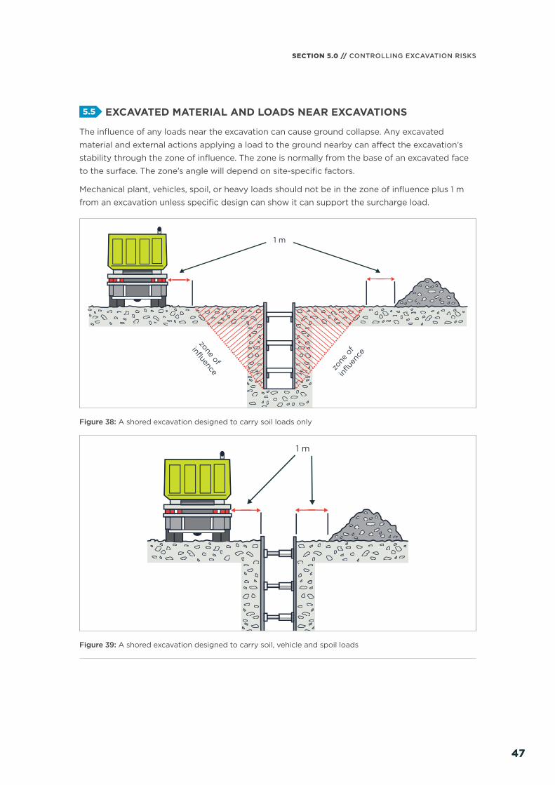
SECTION 5.0 // CONTROLLING EXCAVATION RISKS
4747
5.5 EXCAVATED MATERIAL AND LOADS NEAR EXCAVATIONS
The infl uence of any loads near the excavation can cause ground collapse. Any excavated
material and external actions applying a load to the ground nearby can aff ect the excavation’s
stability through the zone of infl uence. The zone is normally from the base of an excavated face
to the surface. The zone’s angle will depend on site-specifi c factors.
Mechanical plant, vehicles, spoil, or heavy loads should not be in the zone of infl uence plus 1 m
from an excavation unless specifi c design can show it can support the surcharge load.
1 m
zone of
influence zone
of
influ
ence
Figure 38: A shored excavation designed to carry soil loads only
1 m
Figure 39: A shored excavation designed to carry soil, vehicle and spoil loads

GOOD PRACTICE GUIDELINES // EXCAVATION SAFETY
4848
Placing or stacking spoil near an excavated
face puts workers at risk because it adds
an extra load where it is placed or stacked.
For example, placing spoil near the excavated
face may cause it to collapse.
MANAGING THE RISK
Use shoring designed and installed to
carry extra loads, including groundwater
pressures, saturated soil conditions and
saturated spoil. Store spoil away from the
excavation’s zone of infl uence plus 1 m.
If spoil is placed close to an excavation due
to obstructions like fences, buildings, or trees,
the weight of the spoil may overload the
excavated faces. In this case, strengthen the
ground support system at these locations
and provide barriers to prevent the material
falling into the excavation.
If excavating beside an old service line,
place spoil on the opposite side of it to
prevent excessive loading on previously
weakened ground.
If excavating in sloping ground decide which
side of the excavation to place the excavated
material. Consider:
> ground conditions
> access to the excavation
> existing underground services
> needing earthmoving machinery or vehicles
to work or move beside the excavation
> service installation and backfi lling
requirements
> manual work in the excavation.
Placing spoil on the lower side of the
excavation will reduce the eff ective depth
of the excavation and the risk of spoil falling
into the excavation.
Make sure spoil placed on the high side
of the excavation does not increase the risk
of ground collapse, fl ooding, or holding back
run-off water. Place spoil so it channels
rainwater and other run-off water away
from the excavation.
Put the excavatedmaterial here,the trench is nowthis deep
Put the excavatedmaterial here,the trench is nowthis deep
Figure 40: Spoil placement on eff ective excavation depth
5.6 PREVENT FALLS
Work at height means working in a place
where a person could be injured if they fell
from one level to another. This can be above
or below ground level. First try to eliminate
the risk of falling, so far as is reasonably
practicable.
MANAGING THE RISK
Use edge protection or fencing able to
take the weight of a falling worker. Where
shoring extends above 200 mm, toe boards
are not required.
Controls to minimise the risk of falling include:
> fall prevention devices (eg temporary work
platforms, edge protection and guard rails)

SECTION 5.0 // CONTROLLING EXCAVATION RISKS
4949
> work positioning systems (eg industrial
rope access systems)
> fall arrest systems such as catch platforms
> using shoring itself (eg using trench box
extensions or trench sheets taller than
the excavation’s depth). Where shoring
extends above 200 mm toe boards are
not required
> installing and securing covers over
excavations during non-work times
> installing guard rails and edge protection
into the ground immediately around the
excavation
> installing landing platforms or scaff old
towers inside deep excavations
> securing ladders to shoring
> providing clearly defi ned pedestrian
detours
> providing alternative access and egress
points for emergency use
> backfi lling the excavation as work
progresses.
When installing eff ective barriers or
barricades, or guard rails see WorkSafe’s
guidelines Working at Height in New Zealand,
available at www.worksafe.govt.nz
5.7 SAFE ACCESS AND EGRESS
Provide safe access and egress for all workers
at all times. Keep the fl oor of the excavation
clear of anything that would impede workers’
safe egress in an emergency, including:
> debris
> loose spoil
> timber
> tools.
MANAGING THE RISK
In excavations:
> Up to 1.5 m deep, provide ladder,
stairway, or ramp access and egress.
> 1.5 m or more deep, provide ladder or
stairway access and egress.
USING LADDERS
Use ladders constructed of suitable materials,
conforming to appropriate standards, and
maintain them in good condition.
If an excavation is such a small dimension that
it is not reasonably practicable to use ladder
access or egress, provide other means to allow
workers safe access and egress.
For every vertical rise of 6 m, break up ladder
runs with intermediate landings. Where ladders
meet a landing, off set the ladder below from
the ladder above by at least 600 mm.
Unless there are alternative handholds, extend
ladders 1 m above the landing or the top of
the excavation. Fit landing platforms with
guardrails, midrails and/or toe boards.
For more information see WorkSafe’s fact
sheet Safe Working with Ladders and
Stepladders, available at www.worksafe.govt.nz
USING STAIRS AND RAMPS
Use temporary stairways in deep excavations
as they provide safer access and egress than
ladders.
Each fl ight of stairs should have uniform risers
and provide landings of the same width as the
stairs for every vertical rise of 6 m.
If using ramps instead of stairs, the maximum
slope should not exceed 1 in 6, unless traction
cleats are provided at 0.5 m spacing for 1 in 5
slopes, or at 0.4 m spacing for 1 in 4 slopes.
Ramps should not be steeper than 1 in 4.

GOOD PRACTICE GUIDELINES // EXCAVATION SAFETY
5050
Excavations deeperthan 1 m need asecure ladder, rampor scaffold access
Scaffoldingstaircasefor safeand quickevacuation
Figure 41: Scaff olding staircase for a safe and quick evacuation
5.8 MANUAL WORK
During excavation work, there will be circumstances that require some form of manual
work including:
> hand excavation
> lifting
> working in close proximity to plant and other workers.
Tasks which may lead to manual handling injuries include:
> potholing with sharp hand tools
> spotting/exposing underground services in close proximity to excavator buckets
> frequently accessing trenches around existing services
> installing and removing shoring and fall protection
> placing heavy pipes into the excavation
> using compacting equipment
> using breakers
> using drills.
Manual excavation methods are generally used for small, shallow excavations (eg less than
1.5 m deep) in soft soils.
For some excavations, manual work such as trimming by hand will be required. Trimming can
often be accomplished from outside the excavation by shovelling or pushing the material with
a long-handled tool or shovel to the bottom of the excavation, where it can be picked up by
mobile plant.
Preparatory drilling activity and hand drills may increase the risk of musculoskeletal disorders,
including vibration disorders.
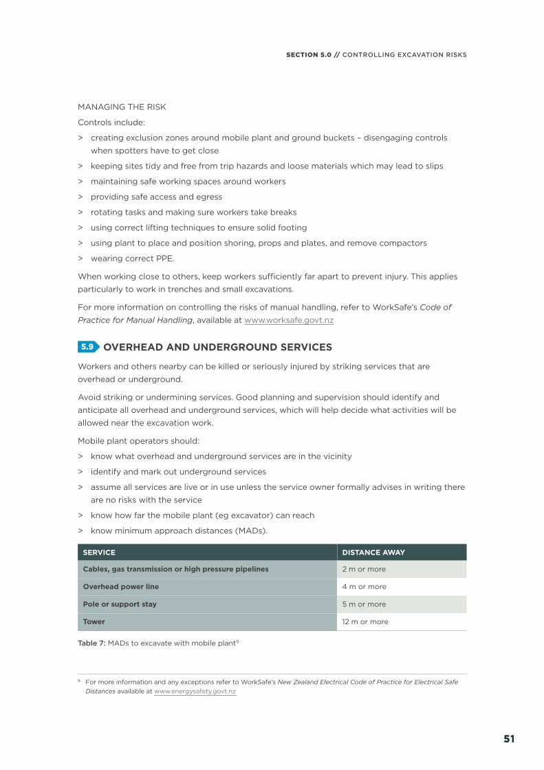
SECTION 5.0 // CONTROLLING EXCAVATION RISKS
5151
MANAGING THE RISK
Controls include:
> creating exclusion zones around mobile plant and ground buckets – disengaging controls
when spotters have to get close
> keeping sites tidy and free from trip hazards and loose materials which may lead to slips
> maintaining safe working spaces around workers
> providing safe access and egress
> rotating tasks and making sure workers take breaks
> using correct lifting techniques to ensure solid footing
> using plant to place and position shoring, props and plates, and remove compactors
> wearing correct PPE.
When working close to others, keep workers suffi ciently far apart to prevent injury. This applies
particularly to work in trenches and small excavations.
For more information on controlling the risks of manual handling, refer to WorkSafe’s Code of
Practice for Manual Handling, available at www.worksafe.govt.nz
5.9 OVERHEAD AND UNDERGROUND SERVICES
Workers and others nearby can be killed or seriously injured by striking services that are
overhead or underground.
Avoid striking or undermining services. Good planning and supervision should identify and
anticipate all overhead and underground services, which will help decide what activities will be
allowed near the excavation work.
Mobile plant operators should:
> know what overhead and underground services are in the vicinity
> identify and mark out underground services
> assume all services are live or in use unless the service owner formally advises in writing there
are no risks with the service
> know how far the mobile plant (eg excavator) can reach
> know minimum approach distances (MADs).
SERVICE DISTANCE AWAY
Cables, gas transmission or high pressure pipelines 2 m or more
Overhead power line 4 m or more
Pole or support stay 5 m or more
Tower 12 m or more
Table 7: MADs to excavate with mobile plant9
9 For more information and any exceptions refer to WorkSafe’s New Zealand Electrical Code of Practice for Electrical Safe Distances available at www.energysafety.govt.nz
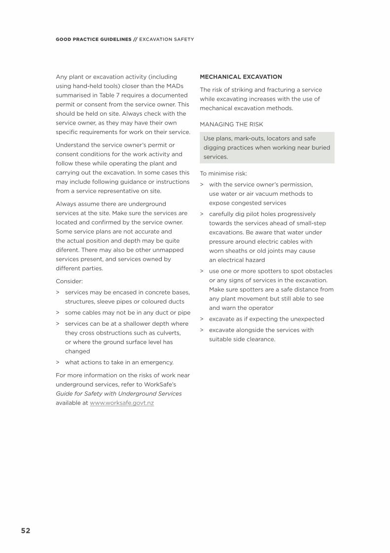
GOOD PRACTICE GUIDELINES // EXCAVATION SAFETY
5252
Any plant or excavation activity (including
using hand-held tools) closer than the MADs
summarised in Table 7 requires a documented
permit or consent from the service owner. This
should be held on site. Always check with the
service owner, as they may have their own
specifi c requirements for work on their service.
Understand the service owner’s permit or
consent conditions for the work activity and
follow these while operating the plant and
carrying out the excavation. In some cases this
may include following guidance or instructions
from a service representative on site.
Always assume there are underground
services at the site. Make sure the services are
located and confi rmed by the service owner.
Some service plans are not accurate and
the actual position and depth may be quite
diferent. There may also be other unmapped
services present, and services owned by
diff erent parties.
Consider:
> services may be encased in concrete bases,
structures, sleeve pipes or coloured ducts
> some cables may not be in any duct or pipe
> services can be at a shallower depth where
they cross obstructions such as culverts,
or where the ground surface level has
changed
> what actions to take in an emergency.
For more information on the risks of work near
underground services, refer to WorkSafe’s
Guide for Safety with Underground Services
available at www.worksafe.govt.nz
MECHANICAL EXCAVATION
The risk of striking and fracturing a service
while excavating increases with the use of
mechanical excavation methods.
MANAGING THE RISK
Use plans, mark-outs, locators and safe
digging practices when working near buried
services.
To minimise risk:
> with the service owner’s permission,
use water or air vacuum methods to
expose congested services
> carefully dig pilot holes progressively
towards the services ahead of small-step
excavations. Be aware that water under
pressure around electric cables with
worn sheaths or old joints may cause
an electrical hazard
> use one or more spotters to spot obstacles
or any signs of services in the excavation.
Make sure spotters are a safe distance from
any plant movement but still able to see
and warn the operator
> excavate as if expecting the unexpected
> excavate alongside the services with
suitable side clearance.

SECTION 5.0 // CONTROLLING EXCAVATION RISKS
5353
Figure 42: Vacuum truck digging a pilot hole
HAND-HELD TOOLS
Using hand-held tools to approach closer to the point of exposing services can risk fracturing
a service if a strike occurs.
MANAGING THE RISK
To minimise risk:
> use detectors to locate services laterally as excavation depth progresses, before working
towards and exposing the services
> dig in line with the service, not at right angles
> use hand-held tools suitable for breaking hard surfaces, provided there is adequate substrate
keeping the tool ends well separated from the services, including making sure:
– not to thrust or spike any hand-held tools into the ground in the close vicinity of services
– hand-held tools (eg shovels and spades) have non-metallic handles and curved edges
to ease covering ground away
– any use of picks, bars or forks is to ease lumps or rocks away. Avoid using metal picks,
bars, forks, drills, or hammers near live electrical cables
> use full body cover with arc-resistant or fl ame-retardant materials when exposing electric
cables, including anti-static properties where gas is a potential hazard.
Once services are exposed:
> identify what the exposed services are:
– service ducts, markings and symbols are in WorkSafe’s Guide for Safety with Underground
Services available at www.worksafe.govt.nz. Old or improperly marked services may vary
a lot from the recommended markings
> always treat any uncovered service as electrical or gas until identifi ed
> check with the service owner for their duct and marking colours and identify what the
underground services are and their status.

GOOD PRACTICE GUIDELINES // EXCAVATION SAFETY
5454
Live electrical work minimum approach distances
For work around live electrical services, use the
MADs set out in section 9 of WorkSafe’s New
Zealand Electrical Code of Practice for Electrical
Safe Distances (ECP 34). Apply MADs from
the hand-held tool to the exposed service.
MADs are available for non-competent
persons. Reduced MADs are available where:
> the owner of the live parts gives written
permission
> competent employees are working near
exposed live parts.
ECP 34 defi nes a ‘competent employee’ as an
employee who can demonstrate the necessary
knowledge, skills and experience to carry out
electrical or telecommunications work in the
vicinity of overhead electric lines, or exposed
live metal, safely and to the standards used
by the employer.
BACKFILLING
Consult with the service owner before
backfi lling. Use appropriate materials to
preserve the support and condition of the
services. Send information to the services
owners so they can update their service plans.
For more information on corridor access
requests and corresponding work authority
permits refer to the New Zealand Utilities
Advisory Group’s (NZUAG) National Code
of Practice for Utility Operators’ Access
to Transport Corridors available at
www.nzuag.org.nz
GAS SERVICE STRIKE
Sparks from striking a gas line can ignite gas
and cause a fi re or explosion. If a gas line is
ruptured, nearby running plant could cause
the gas to ignite.
MANAGING THE RISK
To minimise risk:
> Use plastic (resin) intrinsically rated hand-
held tools or brass tools around gas services.
> If inside an excavator, turn off the ignition
and immediately leave it and the work area
and move to a safe distance.
> Turn off any other sources of ignition.
OVERHEAD POWER LINES
Excavating too close to overhead service
support structures such as wooden poles
can cause these to lean or collapse, putting
workers and others at risk. Breaking
communications cables can also release laser
light that can damage eyesight.
MANAGING THE RISK
To minimise risk:
> carry out operator briefi ngs to:
– clarify any MADs
– understand the mobile plant’s capability
(ie knowing how far the mobile plant
can reach)
> put signs or warning labels in the cab
about the MADs
> temporarily earth the mobile plant
> use markers and spotters
> shield services
> electrical hazards to mobile plant near
overhead power lines and electric cables
> string independently supported fl ag
bunting 1.5 m below the span. The operator
and spotter can use this as a guide. Consult
the service owner to get consent before
stringing any bunting.
If the service owner consents to excavating
closer than the 4 m MAD:
> Protect operators (including operators of
remote controlled plant) from electrical
hazards.
> Keep people away from the mobile plant
in case of electrical contact.
> Have emergency response procedures in
place, if electrical contact does accidently
happen.
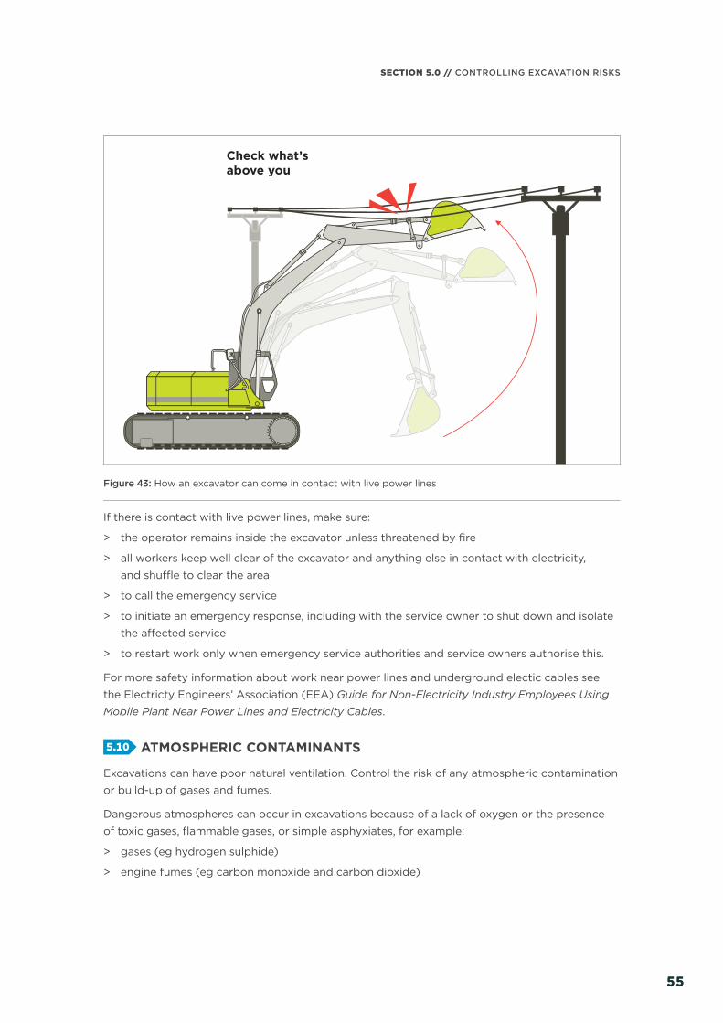
SECTION 5.0 // CONTROLLING EXCAVATION RISKS
5555
Check what’s above you
Figure 43: How an excavator can come in contact with live power lines
If there is contact with live power lines, make sure:
> the operator remains inside the excavator unless threatened by fi re
> all workers keep well clear of the excavator and anything else in contact with electricity,
and shuffl e to clear the area
> to call the emergency service
> to initiate an emergency response, including with the service owner to shut down and isolate
the aff ected service
> to restart work only when emergency service authorities and service owners authorise this.
For more safety information about work near power lines and underground electic cables see
the Electricty Engineers’ Association (EEA) Guide for Non-Electricity Industry Employees Using
Mobile Plant Near Power Lines and Electricity Cables.
5.10 ATMOSPHERIC CONTAMINANTS
Excavations can have poor natural ventilation. Control the risk of any atmospheric contamination
or build-up of gases and fumes.
Dangerous atmospheres can occur in excavations because of a lack of oxygen or the presence
of toxic gases, fl ammable gases, or simple asphyxiates, for example:
> gases (eg hydrogen sulphide)
> engine fumes (eg carbon monoxide and carbon dioxide)

GOOD PRACTICE GUIDELINES // EXCAVATION SAFETY
5656
> leakage from:
– gas bottles
– fuel tanks
– sewers
– drains
– gas pipes
– LPG tanks.
GROUND TYPE ATOMOSPHERIC CONTAMINANTS
Peaty ground methane, hydrogen sulphide
Filled and made ground carbon dioxide, hydrogen sulphide
Reclaimed land and tips methane, carbon dioxide, hydrogen sulphide
Thermal areas hydrogen sulphide, carbon monoxide, carbon dioxide, sulphur dioxide, methyl mercaptan
City streets carbon monoxide, natural gas, carbon dioxide
Service stations petrol and hydrocarbons, kerosene, LPG
Table 8: Other potential sources of harmful gases from types of ground
MANAGING THE RISK
Maintain an atmosphere that is fi t to breathe, limiting any contaminants to safe levels, by:
> never using plant with a combustion engine (eg air compressors, electrical generators)
in an excavation if workers may potentially enter to work
> using gas monitoring devices
> using ventilation – whether natural, forced, or mechanical to control leaking or seeping toxic gas.
To help determine safe levels, compare the results of air monitoring to workplace exposure
standards. For more information, including health-monitoring information, see WorkSafe’s
Workplace Exposure Standards and Biological Exposure Indices, available at www.worksafe.govt.nz
Ventilation systems help to maintain adequate oxygen levels and dilute fl ammable gases, fumes
and certain dusts, such as coal and sulphide. These can ignite if they are present in explosive
limits. Mechanical ventilation also reduces dust, fumes and hazardous contaminants, and can
control air temperature and humidity.
A competent person should design the ventilation system so it provides plenty of ventilation
throughout the excavation. This might include adding localised extraction ventilation to deal
with the dust, heat, or fumes from the excavation. The design should allow for installing
ventilation equipment or ducting as the excavation progresses to maintain adequate air
supply to the working face.
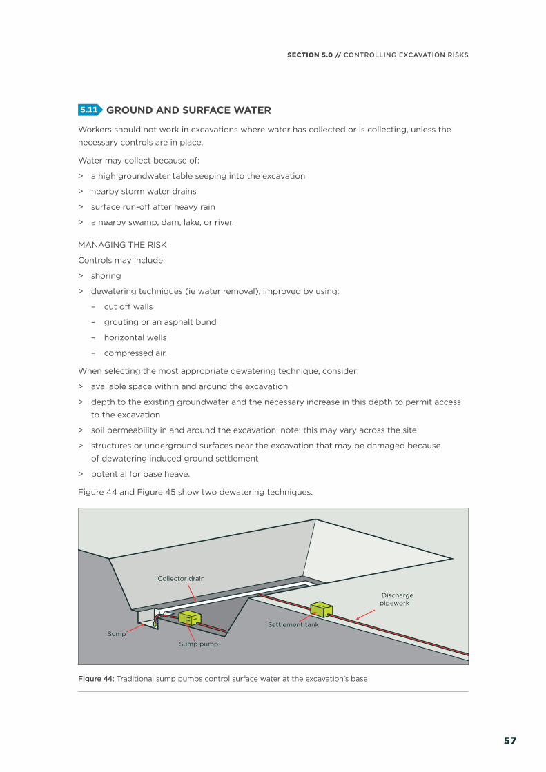
SECTION 5.0 // CONTROLLING EXCAVATION RISKS
5757
5.11 GROUND AND SURFACE WATER
Workers should not work in excavations where water has collected or is collecting, unless the
necessary controls are in place.
Water may collect because of:
> a high groundwater table seeping into the excavation
> nearby storm water drains
> surface run-off after heavy rain
> a nearby swamp, dam, lake, or river.
MANAGING THE RISK
Controls may include:
> shoring
> dewatering techniques (ie water removal), improved by using:
– cut off walls
– grouting or an asphalt bund
– horizontal wells
– compressed air.
When selecting the most appropriate dewatering technique, consider:
> available space within and around the excavation
> depth to the existing groundwater and the necessary increase in this depth to permit access
to the excavation
> soil permeability in and around the excavation; note: this may vary across the site
> structures or underground surfaces near the excavation that may be damaged because
of dewatering induced ground settlement
> potential for base heave.
Figure 44 and Figure 45 show two dewatering techniques.
Dischargepipework
Settlement tank
Sump pump
Sump
Collector drain
Figure 44: Traditional sump pumps control surface water at the excavation’s base

GOOD PRACTICE GUIDELINES // EXCAVATION SAFETY
5858
Depressionpits
Waterlevelduring dewatering
Filter
Water levelbefore dewatering
Dewatering pump
Suction header pipe
Wellpoint
1 m1 m
Figure 45: Use well point pumping for lowering groundwater by up to 6 m
5.12 CONTAMINATED SOILS AND GROUNDWATER
Contaminated soils and groundwater can pose a risk to human health through:
> direct contact
> inhaling dust or vapours
> petroleum hydrocarbon contaminated soil
> general landfi ll
> suspected asbestos containing material (ACM).
Before starting any excavation work, assess the likelihood of encountering contaminated soils
or groundwater. If contamination is suspected or discovered, the risk to human health and the
environment will require reassessment.
Health monitoring applies to workers if they are at risk of airborne asbestos exposure when
carrying out ongoing asbestos-related work or asbestos removal work and are at risk of exposure
to airborne asbestos when doing that work.
For more information see WorkSafe’s position statement Managing Occupational Health on
Potentially Contaminated Sites, available at www.worksafe.govt.nz

SECTION 5.0 // CONTROLLING EXCAVATION RISKS
5959
The Resource Management Act 1991 contains
prohibitions against the discharge of
contaminants into or onto the land, the water,
or the air unless the discharge is expressly
allowed by a national environmental standard,
a rule in a regional plan or a resource consent.
Contaminated soils and groundwater can also
harm the environment through:
> stormwater and groundwater
> dust
> moving or disposing of contaminated soil.
Indicators of potential contamination include,
but are not limited to, unusual odours and
discoloured or stained water seeps and soils
where the land is potentially or actually
contaminated.
A land use consent may be required from the
local authority to excavate or disturb soils at
the site. Seek further advice from a suitably
qualifi ed and experienced practitioner.
5.13 USING EXPLOSIVES
Construction work that uses explosives is
subject to the Hazardous Substances and New
Organisms Act 1996 (HSNO) and regulations.
All possession, storage, handling, and use of
explosives must be carried out in compliance
with this legislation.
The PCBU should consult a competent person
in the controlled application of explosives
for carrying out the excavation work before
deciding whether explosives should be used
for the excavation.
Transport explosives in accordance with the
Land Transport Act 1998 and regulations and
HSNO.
Explosives must only be used by an approved
handler who is qualifi ed in explosives safety
and has experience in this type of work.
If explosives are used in excavation work,
an approved handler should develop the
blast management plan and be responsible
for all aspects of the use of explosives.
For more information on the use of explosives
for excavation work, refer to AS 2187.2:
Explosives – storage and use – use of explosives.

GOOD PRACTICE GUIDELINES // EXCAVATION SAFETY
PLANT AND EQUIPMENT
06/
6060
IN THIS SECTION:6.1 Checking the plant, equipment
and materials 6.2 Using plant 6.3 Plant and vehicle operation
near excavations 6.4 Blind spots 6.5 Operator protection 6.6 Quick hitches 6.7 Load-lifting

61
SECTION 6.0 // PLANT AND EQUIPMENT
61
Use suitable plant and equipment maintained in good condition to carry out excavation work safely.
Various plant and equipment can carry out
excavation work. Excavators in a range of
sizes can:
> extract soil from within an excavation
> lift and move materials
> install and remove shoring.
Make sure to use an appropriate excavator for
the excavation work and properly plan and risk
assess any lifting operations by the excavator
before carrying out the operation.
To use plant safely:
> make sure the plant is operated by a
competent operator
> fi t suitable guards and protective devices
> display the working load limit and make
sure any load measurement devices are
operating correctly
> maintain plant in accordance with the
manufacturer/supplier’s instructions or
relevant standards
> fi t excavators with an operating weight
of seven tonnes or more with hose burst
protection valves
> carry out regular planned inspections
and maintenance in accordance with the
manufacturer’s recommendations to make
sure the mobile plant works safely, whether
leased, hired, or owned
> conduct both mechanical and electrical
testing
> carry out the following checks:
– daily pre-start checks on the general
condition and maintenance of the plant
– regular inspections by a competent
person, in accordance with the
manufacturer/supplier’s specifi cations
or relevant standards.
Plant defects should be reported immediately
to the PCBU. If a defect is likely to pose an
immediate or imminent risk to health and
safety, remove the plant from service until
the defect is fi xed.
6.1 CHECKING THE PLANT, EQUIPMENT AND MATERIALS
Check plant, equipment, and materials before
arriving at the worksite. Make sure the plant
and equipment are fi t-for-purpose and in good
working order.
If applicable, carry out checks before leaving
the depot, and report any concerns according
to company procedures, for example by
tagging unsafe equipment. Do a fi nal check
when at the site and look over the area before
starting work.
Make sure the materials are suitable for the job
and the quantities are correct.
Check that enough material has been ordered,
for example geotextiles and metal for backfi lling.

GOOD PRACTICE GUIDELINES // EXCAVATION SAFETY
6262
Check there is appropriate PPE for the job and
it is in good condition. Correct PPE includes:
> high-visibility clothing
> hard hat
> safety footwear
> hearing and eye protection.
6.2 USING PLANT
A wide range of powered mobile plant,
including earthmoving machinery can carry
out excavation work. To select suitable plant,
consider:
> the task
> site access and restrictions
> type and depth of excavation
> ground conditions
> the mobile plant’s size and reach
> hazards (eg overhead and underground
services)
> the volume of material to be excavated and
transported
> where the excavated material is to be
located and stored.
A competent operator should use earthmoving
machinery for its originally designed purpose.
Earthmoving machinery operators must
demonstrate they are competent to operate
the specifi c type of plant and any fi tted
attachments.
USING EARTHMOVING MACHINERY
Bulldozers and scrapers are often used
to prepare a work area for further specifi c
excavation.
Bulldozers typically excavate and move large
amounts of material short distances. They
can be equipped with hydraulically-operated
rippers at the back which are capable of
loosening the hardest of sedimentary rocks.
Self-propelled rubber-tyred scrapers can
excavate and haul very large quantities of
material economically over long distances
at relatively high speed. Because of the large
potential soil output and speeds of modern
scrapers, pay careful attention to:
> job layout
> haul roads
> vehicle pathways
> worker movements and overall traffi c
management.
Temporary haul roads should be well
constructed and maintained to let plant
operators complete the work safely.
Large earthmoving machinery such as
bulldozers should not operate close to an
overhang or a deep excavation, as the weight
may collapse the excavation.
Excavation work exceeding 1.5 m deep is
typically done by excavators or specialised
plant such as tunnelling machines and raise-
bores. Most of these types of plant have
an element of mobility, although tunnelling
machines typically have restricted movement.
Other plant used in excavation work includes
backhoes, rubber-tyred loaders, skid steer
loaders (eg bobcats), trench diggers, graders
and tip trucks.

63
SECTION 6.0 // PLANT AND EQUIPMENT
63
6.3 PLANT AND VEHICLE OPERATION NEAR EXCAVATIONS
Powered mobile plant should not operate or travel near the edge of an excavation unless the
shoring can support such loads.
Plant should approach end-on to excavations. If this is not practicable, make sure workers in the
excavation get out when the plant is within the excavation’s zone of infl uence or move away and
stand further down the excavation.
Workers should never stand under a load being lifted over the excavation.
1 m
Excavatedmaterial
Figure 46: Prevent plant operation near excavations
Wheel stopper
Figure 47: Wheel stopper restricting plant movement
Physical barriers such as wheel stoppers are one way of restricting plant movement near
an excavation.
Table 9 outlines some excavation hazards and some controls to consider.
CONSIDER EXAMPLE CONTROLS
Attachment failure > use quick hitches to secure attachments
> make sure the operator is familiar with and able to implement and manage any quick hitch used
> make sure the operator checks any pins
Buried contaminants (eg asbestos)
> conduct a site assessment and carry out any remedial action
Lack of visibility > make sure operators can see areas where people may be at risk from the operation of the machine
> equip excavators with adequate visibility aids or use a spotter/s
Plant instability > set up as per industry recommendations
Plant striking workers > keep people away from areas of plant operation. Most excavator related deaths involve a person working in the vicinity of the excavator rather than the driver
> use barriers, signage or a spotter

GOOD PRACTICE GUIDELINES // EXCAVATION SAFETY
6464
CONSIDER EXAMPLE CONTROLS
Spoil placement > safe distance of at least 1 m from edge
Spotter > use a trained spotter in a safe position to direct excavator operation and any pedestrian movements
> make sure the spotter and operator understand the signals they will use and agree on the way to communicate with each other
Strike hazards > select plant with minimal tail swing if slewing in a confi ned area
> maintain over 0.5 m of clearance between any part of the machine, particularly the ballast weight, and the nearest obstruction
Table 9: Typical excavator operation hazards
6.4 BLIND SPOTS
Operators of powered mobile plant can often have severely restricted visibility of ground
workers or nearby pedestrians, particularly those close to the plant.
Figure 48 and Figure 49 show some of the blind spots for operators of typical excavation
equipment.
In Figure 49 the operator’s visibility of the left rear relies on mirrors. Note there will always
be a blind spot for the operator in line with the boom. Workers should approach the operator
from a point where everyone can clearly see each other.
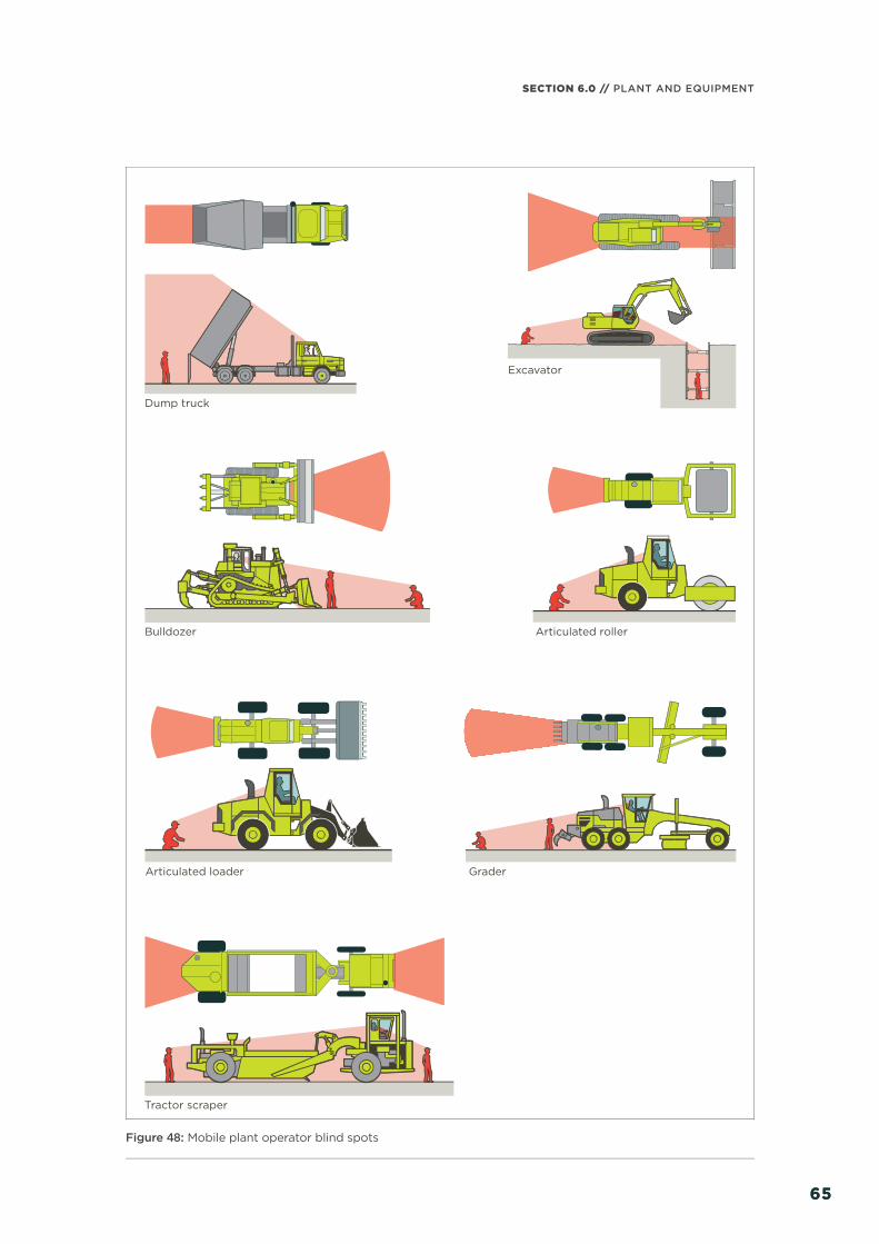
65
SECTION 6.0 // PLANT AND EQUIPMENT
65
Dump truck
Excavator
Bulldozer Articulated roller
Articulated loader Grader
Tractor scraper
Figure 48: Mobile plant operator blind spots

GOOD PRACTICE GUIDELINES // EXCAVATION SAFETY
6666
Swing radius
Safe approach
Blind spot
Pinch area
Figure 49: Safe approach zone for an excavator
Equip mobile plant operating near workers
or other plant with warning devices (eg a
reversing alarm or a revolving light; vehicles
can also be fi tted with reversing cameras).
Establish an eff ective system of
communication based on two-way
acknowledgement between mobile plant
operators and ground workers before work
starts. Train relevant workers in the procedures
before they start work. The system should
stop ground workers from approaching
mobile plant until the operator has agreed
to their request to approach. Similarly, the
system should stop operators from moving
plant closer than a set distance from ground
workers until ground workers have advised the
operator that they are aware of the proposed
movement.
Mobile plant operators and workers should be
familiar with the blind spots of the plant being
used. Provide induction-training programs
emphasising the dangers of working in
close proximity to mobile plant, and provide
adequate supervision.
Make sure operators and workers wear high-
visibility PPE.
EXCLUSION ZONES AND SPOTTERS
Exclusion zones and separating workers from
mobile plant should be the fi rst option for
managing this risk. If exclusion is not possible,
use spotters to control operations when
workers are in the immediate area. A spotter
should be in constant contact with the mobile
plant operator.
Figure 50: A spotter helping a reversing vehicle
6.5 OPERATOR PROTECTION
Powered mobile plant should be equipped
with an appropriate combination of operator
protection devices, for example an enclosed
cabin and seat belts, to prevent the operator
from ejecting from the cab or being struck
by falling objects.
Any earthmoving machinery weighing more
than 700 kgs, not including attachments, and
designed to have a seated operator, should
have an appropriate operator protective
structure fi tted. These are either roll-over
protective structures (ROPS), falling object
protective structures (FOPS) or both,
depending on the application. Self-propelled
mechanical mobile plant must, so far as is
reasonably practicable, be fi tted with roll-over
protection and seat belts.
For more information see WorkSafe’s Approved
Code of Practice for Operator Protective
Structures on Self-Propelled Mobile Mechanical
Plant, available at www.worksafe.govt.nz

67
SECTION 6.0 // PLANT AND EQUIPMENT
67
6.6 QUICK HITCHES
Quick hitches allow a bucket or other
attachment to be quickly and easily connected
and disconnected from an excavator or
backhoe arm, saving signifi cant time during
mobile plant operation.
A pin holds the attachment in place against
the quick hitch and insures against accidental
release. However, a manual quick hitch may
still operate without the retaining pin in place
and then suddenly, without warning, swing
open or fall completely. If this happens when
lifting over or close to a person the result
is likely to be fatal.
MANAGING THE RISK
Before operating the mobile plant, make
sure the operator:
> checks the attachment is securely
attached by the quick hitch
> sets up an exclusion zone around the
area where the excavator is operating.
Controls include:
> using a suitable semi or fully automatic
system instead of a manually operated
quick hitch system
> training excavator operators on the use of
quick hitches
> ensuring that excavator operators are
competent to use the specifi c hitch for the
machine they use
> operators only using pins designed for this
specifi c use (the manufacturer-specifi ed
retaining pin must be available on the
machine)
> attachment information clearly displayed
or present with the machine identifying:
– model and serial number
– manufacturer’s name
– weight and maximum rated capacity
– each lifting point’s capacity
> setting up a system for checking that the
pin is in place before starting the work and
every time a diff erent attachment is fi tted
> conducting random checks to make sure
precautions are implemented and followed.
Before operating the mobile plant the operator
should:
> check the attachment size is suitable
and compatible with the quick hitch
> check the quick hitch is kept in good
working order
> physically check the safety pin is securely
in place or the automatic system has
engaged correctly:
– before starting work, and
– when fi tting a diff erent attachment
> make sure an exclusion zone is set up when
using the excavator and for attachment
fi tting or removal. If there are other workers
on the construction site the exclusion
zone applies to them, even if they are not
involved in the excavator operation.
For more information on quick hitches see
WorkSafe’s fact sheet Using Quick Hitches
Safely, available at www.worksafe.govt.nz
6.7 LOAD-LIFTING
Items of mobile plant (including earthmoving
equipment), not originally designed as a crane,
and used for load-lifting incidental to their
principal function are entirely exempt from the
Health and Safety in Employment (Pressure
Equipment, Cranes, and Passenger Ropeways)
Regulations 1999 subject to the following
conditions10 as applicable:
> lifting points and equipment used for
rigging loads must be certifi ed by a
Chartered Professional Engineer
10 ‘Notice Under the Health and Safety in Employment (Pressure Equipment, Cranes, and Passenger Ropeways) Regulations 1999’ (24 September 2015) 104 New Zealand Gazette. www.gazette.govt.nz/notice/id/2015-go5666
GOOD PRACTICE GUIDELINES // EXCAVATION SAFETY
6868
> in the case of new and used hydraulic
excavators with an operating weight
of seven tonne or more, the following
additional conditions apply:
– the equipment is not to be modifi ed to
make it operate as a crane other than
the provision of a lifting point
– the equipment is to have a loading chart
available to operators
– operators and ground support
personnel are to be adequately trained
– operations are to be carried out in
accordance with the Approved Code
of Practice for Load-Lifting Rigging
– hose burst protection valves are
required (except for load-lifting mobile
plant used in forestry operations that
do not involve the construction of
forest roads).

APPENDICES
07/
69
IN THIS SECTION:7.1 Appendix A: Legal framework 7.2 Appendix B: Safe system
of work considerations 7.3 Appendix C: Trenching
checklist 7.4 Appendix D: Notifi cations
to WorkSafe 7.5 Appendix E: More information 7.6 Appendix F: Glossary

GOOD PRACTICE GUIDELINES // EXCAVATION SAFETY
7070
7.1 APPENDIX A: LEGAL FRAMEWORK
All excavation work must comply with HSWA and associated regulations. Table 10 lists the
specifi c duties under the HSE Regulations that apply to excavations in construction work.
Regulation 23
Application of Regulations 24 and 25
(1) In Regulations 24 and 25, the term employer means—
(a) every employer, in relation to every workplace under the control of that employer in which any construction work is carried out; and
(b) every person who controls a workplace in which any construction work is carried out.
(2) In Regulations 24 and 25, the term employee,—
(a) in relation to an employer of the kind described in subclause (1)(a), means an employee of that employer; and
(b) in relation to a person of the kind described in subclause (1)(b), means a person working in the workplace.
Regulation 24
Excavations with face more than 1.5 m high
(1) Subject to subclause (2), every employer must, so far as is reasonably practicable, ensure that, where any face of any excavation is more than 1.5 m high, that face is shored.
(2) Subclause (1) does not apply where—
(a) the face is cut back to a safe slope; or
(b) the material in the face is of proven good standing quality under all reasonably foreseeable conditions of work and weather; or
(c) by reason of the nature of the work and the position of any employee in the vicinity, there is no danger to any employee; or
(d) the provision of shoring is impracticable or unreasonable by reason of the nature of the work and the employer has, so far as is reasonably practicable, taken steps to ensure that other precautions are taken to make the face as safe as possible in the circumstances.
(3) Every employer must, so far as is reasonably practicable, ensure that any shoring used in any excavation at the workplace—
(a) consists of materials that are suitable for the purpose for which they are to be used, of sound quality, and adequate in strength for the particular use; and
(b) has bracings, jacks, and struts that are securely held to prevent accidental displacement, and packings and wedges that are held by nails or spikes; and
(c) is placed in a proper manner by an experienced person under competent supervision; and
(d) is not altered, dismantled, or interfered with except on the instructions of the employer or a representative of the employer.
Regulation 25
Excavations of hazardous depth
Every employer must, so far as is reasonably practicable, ensure, where any excavation is—
(a) readily accessible to any person; and
(b) likely to collect or retain water of such a depth as to constitute a danger to any person,—
that—
(c) any such excavation is covered or fenced, when no employee is in the immediate vicinity to prevent access to it by any person; and
(d) any such excavation created in the course of the work is covered, fenced, or fi lled at the completion of the work.
Table 10: Duties in relation to excavations in the HSE Regulations

SECTION 7.0 // APPENDICES
7171
TUNNELLING OPERATIONS
Under clause 4 of Schedule 3 of HSWA a tunnelling operation is the extraction of fi ll to create,
extend, or enlarge a tunnel or shaft. Tunnelling operations are subject to Schedule 3 of HSWA
and the MOQO Regulations, except operations involving:
> tunnels or shafts of any length where no-one ordinarily works underground
> tunnels or shafts that are or will be 15 m or less, where one or two workers ordinarily work
underground at any one time, and:
– no explosives are used, and
– methane concentrations will not exceed 0.25% of the air in the tunnel or shaft.
BUILDING LEGISLATION
The Building Act 2004 and Building Regulations 1992 will generally apply if excavations are
associated with constructing, altering, demolishing or removing a building. This also includes site
work and building-related design work.
For more information on building legislation and controls, refer to the Ministry of Business,
Innovation and Employment’s website www.building.govt.nz
OTHER REQUIREMENTS
Consider the requirements of any applicable:
> codes of practice
> engineering standards
> laws and regulations and any subsequent amendments
> local authorities, by-laws and district plans.
Relevant legislation to consider may include the following Acts and regulations made under them:
> Building Act 2004
> Electricity Act 1992
> Gas Act 1992
> Land Transport Management Act 2003
> Local Government Act 2000
> Resource Management Act 1991
> Telecommunications Act 2001

GOOD PRACTICE GUIDELINES // EXCAVATION SAFETY
7272
7.2 APPENDIX B: SAFE SYSTEM OF WORK CONSIDERATIONS
Planning considerations should include discussions on:
> permits/consents/notifi cations
> service mark-outs and locations
> site-specifi c documentation which could include:
– health and safety policy
– summary worksite safety plan
– worksite emergency procedures
– worksite safety induction card
– visitor and worksite induction register
– accident/incident register
– injury/ill-health/incident reporting
– hazard identifi cation
– site-specifi c risk assessment
– safe or standard operating procedures
> environmental plan (ie erosion and sediment control)
> quality plan
> overhead services and underground service plans
> construction plans
> nature or condition of the ground, for example:
– ground water
– depth of excavation
– soil conditions
– confi ned space and ventilation
> weather conditions (eg time of year, expected conditions etc)
> static and dynamic loads near the excavation
> interaction with other trades
> site access and security
> traffi c management and public safety
> type of plant and equipment to be used for excavation work
> the length of time the excavation is to remain open
> provision of adequate facilities.

SECTION 7.0 // APPENDICES
7373
7.3 APPENDIX C: TRENCHING CHECKLIST
This is a basic checklist for trench work. Add other items as appropriate to a particular site or job.
1. Is the surface clear of plant, spoil heaps and materials for at least 1 m from the edge of the
excavation?
2. Are spoil heaps properly controlled and will they stay like this in wet weather?
3. Is the trench clear of workers while the spoil heap is being worked on?
4. Is the space between the trench and the spoil heap clear of pipes, bricks, stones, tools, etc?
5. Is the work properly fenced off and ‘signed’ during the day. Is the work properly fenced off ,
‘signed’, guarded and lit during the night?
6. Is access adequate without anyone having to jump across? Are footbridges with guard rails
available and being used?
7. Are ladders available and being used?
8. Is the supervisor making sure that no-one climbs on the timbering?
9. Is the trench safe from exhaust gases from plant working in the trench or nearby?
10. Does everyone know where the buried services are and are they clearly marked?
11. Are the workers who are excavating and shoring the trench experienced in this sort of work?
12. Are they working at safe distances from each other?
13. Is the ground as the design assumed?
14. Is there any movement or deterioration of the ground that may put adjacent services, roads
or structures at risk?
15. Is the area aff ected by blasting or other heavy vibrations?
16. Is the ground water level as used in the design (ie not higher)?
17. Are proper sumps provided?
18. Does the pumping arrangement avoid drawing material from behind the sheeting?
19. Is the work being done in accordance with the drawings or sketches? If not, is the variation
permissible?
20. Are unsheeted faces safe, with no sign of peeling away?
21. Are materials of the correct design size and quality?
22. Are wedges tight?
23. Is timbering free of damage from skips?
24. Are waling and strut spacing within +/-100 mm?
25. Are defl ections excessive?
26. Are all struts horizontal and positioned squarely to the walings (within 1 in 40)?
27. Are frames supported against downward movement (by hangers or lip blocks, puncheons
and sole plates)?
28. Have correct pins been used in steel trench struts?
29. Is the method of withdrawing sheeting and support for the trench during backfi ll safe?
30. Is the work area tidy?
31. Are stops provided for mobile plant?
32. Is visibility adequate in the trench?
33. Is PPE available and being used?
GOOD PRACTICE GUIDELINES // EXCAVATION SAFETY
7474
7.4 APPENDIX D: NOTIFICATIONS TO WORKSAFE
NOTIFICATION OF PARTICULAR HAZARDOUS WORK
Employers and the person in control of the workplace must notify WorkSafe at least 24 hours’
before doing any hazardous work (as defi ned below).
These notices help WorkSafe plan workplace visits to promote health and safety for everyone
in or near a workplace.
Notify WorkSafe by either:
> fi ling a Notifi cation of Particular Hazardous Work online at www.worksafe.govt.nz
> downloading the notifi cation form and posting or faxing it to WorkSafe.
WORK THAT NEEDS TO BE NOTIFIED TO WORKSAFE
Defi ned in the HSE regulations as:
> any commercial logging or tree-felling
> any construction work where:
– workers could fall 5 m or more (excluding work on a house up to two-storeys high, a power
or telephone line, or carried out from a ladder only, or minor or routine maintenance or
repair work)
– scaff olding from which someone could fall 5 m or more while being put up or dismantled
– an appliance (other than a self-propelled mobile crane, excavator or forklift) has to lift
weights of half a tonne (500 kg) or more a height of 5 m or more
– people have to work in an excavation that is more than 1.5 m deep and which is deeper
than it is wide at the top
– workers need to work in any kind of heading, excavation or drive where there is ground
cover overhead
– work in any excavation in which any face has a vertical height of more than 5 m and an
average slope steeper than a ratio of 1 horizontal to 2 vertical
– work where explosives are used, or stored for this purpose
– workers need to breathe air that is or has been compressed or breathe a respiratory
medium other than air.
SECTION 7.0 // APPENDICES
7575
NOTIFIABLE EVENTS
A notifi able event is when someone dies or when a notifi able incident, illness or injury occurs as
a result of work. WorkSafe must be informed of all notifi able events. Notifi able injuries, illnesses
and incidents are specifi ed in HSWA.
NOTIFIABLE INCIDENTS
HSWA requires PCBUs to notify WorkSafe if there is an unplanned or uncontrolled incident at
a workplace that exposes a person (worker or otherwise) to a serious risk to their health and
safety arising from immediate or imminent exposure to:
> a substance escaping, spilling, or leaking
> an implosion, explosion or fi re
> gas or steam escaping
> pressurised substance escaping
> electric shock
> the fall or release from height of any plant, substance or object
> damage to or collapsing, overturning, failing or malfunctioning of any plant that is required
to be authorised for use
> the collapse or partial collapse of a structure
> the collapse or failure of an excavation or any shoring supporting an excavation
> the inrush of water, mud, or gas in workings in an underground excavation or tunnel
> the interruption of the main system of ventilation in an underground excavation or tunnel
> a collision between two vessels, a vessel capsize, or the inrush of water into a vessel
> any other incident declared in regulations to be a notifi able incident.

GOOD PRACTICE GUIDELINES // EXCAVATION SAFETY
7676
7.5 APPENDIX E: MORE INFORMATION
ENVIRONMENTAL PROTECTION AUTHORITY
For information about how to manage hazardous substances visit the Environmental Protection
Authority’s website www.epa.govt.nz or call 0800 376 234.
LOCAL COUNCIL
Your council might have additional rules that need to be met. Check with your local council for
specifi c rules that apply in your region.
LOCAL UTILITY OWNERS
Check any local utility owners’ websites for additional procedures that may need to be met –
look for headings like safety, working safely or public safety.
NEW ZEALAND LEGISLATION
To access all legislation including Acts and regulations visit the New Zealand Legislation website
www.legislation.govt.nz
THE INSTITUTION OF PROFESSIONAL ENGINEERS NEW ZEALAND (IPENZ)
A list of competent engineers can be found on the IPENZ website, under the Chartered
Professional Engineers (CPEng) Register available at www.ipenz.nz
WORKSAFE NEW ZEALAND
For information and guidance about health and safety visit WorkSafe’s website www.worksafe.
govt.nz or call 0800 030 040.
For information and guidance specifi cally about electrical or gas safety visit WorkSafe’s website
www.energysafety.govt.nz or call 0800 030 040.
STANDARDS
AS 1657 Fixed platforms, walkways, stairways and ladders – design, construction and installation
AS 2187.2 Explosives – storage and use – use of explosive
AS 2865 Confi ned spaces
AS 4744.1 Steel shoring and trench lining equipment
AS 5047 Hydraulic shoring and trench lining equipment
AS/NZS 1576 Scaff olding (series)
AS/NZS 1892 Portable ladders (series)
BS EN 13331-1 Trench lining systems. Product specifi cations
BS EN 13331-2 Trench lining systems. Assessment by calculation or test
BS EN 1537 Execution of special geotechnical works – ground anchors
BS 8081 Code of practice for grouted anchors
FHWA-IF-99-015 Ground anchors and anchored systems
NZS 3603 Timber structures standard

SECTION 7.0 // APPENDICES
7777
GUIDANCE
Approved Code of Practice for Operator Protective Structures on Self-Propelled Mobile
Mechanical Plant
WorkSafe New Zealand www.worksafe.govt.nz
Code of Practice for Temporary Traffi c Management: Part 8 of the Traffi c Control Devices Manual
New Zealand Transport Agency www.nzta.govt.nz
Excavation Work Code of Practice
Safe Work Australia www.safeworkaustralia.gov.au
Guide for Safety with Underground Services
WorkSafe New Zealand www.worksafe.govt.nz
Health and Safety at Opencast Mines, Alluvial Mines and Quarries
WorkSafe New Zealand www.worksafe.govt.nz
National Code of Practice for Utility Operators’ Access to Transport Corridors
New Zealand Utilities Advisory Group (NZUAG) www.nzuag.org.nz
New Zealand Electrical Code of Practice for Electrical Safe Distances (NZECP 34:2001)
WorkSafe New Zealand www.energysafety.govt.nz
Safety around Excavations
WorkSafe New Zealand www.worksafe.govt.nz
Safe Use of Machinery
WorkSafe New Zealand www.worksafe.govt.nz
Using Quick Hitches Safely
WorkSafe New Zealand www.worksafe.govt.nz
Working with Ladders and Stepladders
WorkSafe New Zealand www.worksafe.govt.nz
Workplace Exposure Standards and Biological Exposure Indices
WorkSafe New Zealand www.worksafe.govt.nz
Your Guide to Working Safe on the Road and Staying Alive
New Zealand Utilities Advisory Group (NZUAG) www.powerco.co.nz
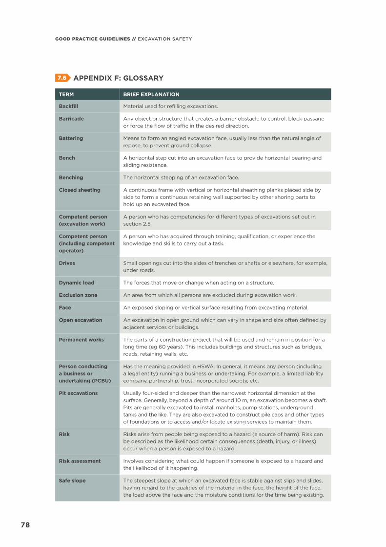
GOOD PRACTICE GUIDELINES // EXCAVATION SAFETY
7878
7.6 APPENDIX F: GLOSSARY
TERM BRIEF EXPLANATION
Backfi ll Material used for refi lling excavations.
Barricade Any object or structure that creates a barrier obstacle to control, block passage or force the fl ow of traffi c in the desired direction.
Battering Means to form an angled excavation face, usually less than the natural angle of repose, to prevent ground collapse.
Bench A horizontal step cut into an excavation face to provide horizontal bearing and sliding resistance.
Benching The horizontal stepping of an excavation face.
Closed sheeting A continuous frame with vertical or horizontal sheathing planks placed side by side to form a continuous retaining wall supported by other shoring parts to hold up an excavated face.
Competent person (excavation work)
A person who has competencies for diff erent types of excavations set out in section 2.5.
Competent person (including competent operator)
A person who has acquired through training, qualifi cation, or experience the knowledge and skills to carry out a task.
Drives Small openings cut into the sides of trenches or shafts or elsewhere, for example, under roads.
Dynamic load The forces that move or change when acting on a structure.
Exclusion zone An area from which all persons are excluded during excavation work.
Face An exposed sloping or vertical surface resulting from excavating material.
Open excavation An excavation in open ground which can vary in shape and size often defi ned by adjacent services or buildings.
Permanent works The parts of a construction project that will be used and remain in position for a long time (eg 60 years). This includes buildings and structures such as bridges, roads, retaining walls, etc.
Person conducting a business or undertaking (PCBU)
Has the meaning provided in HSWA. In general, it means any person (including a legal entity) running a business or undertaking. For example, a limited liability company, partnership, trust, incorporated society, etc.
Pit excavations Usually four-sided and deeper than the narrowest horizontal dimension at the surface. Generally, beyond a depth of around 10 m, an excavation becomes a shaft. Pits are generally excavated to install manholes, pump stations, underground tanks and the like. They are also excavated to construct pile caps and other types of foundations or to access and/or locate existing services to maintain them.
Risk Risks arise from people being exposed to a hazard (a source of harm). Risk can be described as the likelihood certain consequences (death, injury, or illness) occur when a person is exposed to a hazard.
Risk assessment Involves considering what could happen if someone is exposed to a hazard and the likelihood of it happening.
Safe slope The steepest slope at which an excavated face is stable against slips and slides, having regard to the qualities of the material in the face, the height of the face, the load above the face and the moisture conditions for the time being existing.
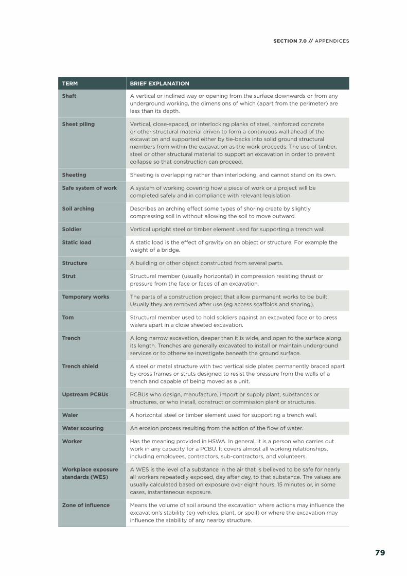
SECTION 7.0 // APPENDICES
7979
TERM BRIEF EXPLANATION
Shaft A vertical or inclined way or opening from the surface downwards or from any underground working, the dimensions of which (apart from the perimeter) are less than its depth.
Sheet piling Vertical, close-spaced, or interlocking planks of steel, reinforced concrete or other structural material driven to form a continuous wall ahead of the excavation and supported either by tie-backs into solid ground structural members from within the excavation as the work proceeds. The use of timber, steel or other structural material to support an excavation in order to prevent collapse so that construction can proceed.
Sheeting Sheeting is overlapping rather than interlocking, and cannot stand on its own.
Safe system of work A system of working covering how a piece of work or a project will be completed safely and in compliance with relevant legislation.
Soil arching Describes an arching eff ect some types of shoring create by slightly compressing soil in without allowing the soil to move outward.
Soldier Vertical upright steel or timber element used for supporting a trench wall.
Static load A static load is the eff ect of gravity on an object or structure. For example the weight of a bridge.
Structure A building or other object constructed from several parts.
Strut Structural member (usually horizontal) in compression resisting thrust or pressure from the face or faces of an excavation.
Temporary works The parts of a construction project that allow permanent works to be built. Usually they are removed after use (eg access scaff olds and shoring).
Tom Structural member used to hold soldiers against an excavated face or to press walers apart in a close sheeted excavation.
Trench A long narrow excavation, deeper than it is wide, and open to the surface along its length. Trenches are generally excavated to install or maintain underground services or to otherwise investigate beneath the ground surface.
Trench shield A steel or metal structure with two vertical side plates permanently braced apart by cross frames or struts designed to resist the pressure from the walls of a trench and capable of being moved as a unit.
Upstream PCBUs PCBUs who design, manufacture, import or supply plant, substances or structures, or who install, construct or commission plant or structures.
Waler A horizontal steel or timber element used for supporting a trench wall.
Water scouring An erosion process resulting from the action of the fl ow of water.
Worker Has the meaning provided in HSWA. In general, it is a person who carries out work in any capacity for a PCBU. It covers almost all working relationships, including employees, contractors, sub-contractors, and volunteers.
Workplace exposure standards (WES)
A WES is the level of a substance in the air that is believed to be safe for nearly all workers repeatedly exposed, day after day, to that substance. The values are usually calculated based on exposure over eight hours, 15 minutes or, in some cases, instantaneous exposure.
Zone of infl uence Means the volume of soil around the excavation where actions may infl uence the excavation’s stability (eg vehicles, plant, or spoil) or where the excavation may infl uence the stability of any nearby structure.

Notes

DISCLAIMER
WorkSafe New Zealand has made every eff ort to ensure the information contained in this publication is reliable, but makes no guarantee of its completeness. WorkSafe may change the contents of this guide at any time without notice.
This document is a guideline only. It should not be used as a substitute for legislation or legal advice. WorkSafe is not responsible for the results of any action taken on the basis of information in this document, or for any errors or omissions.
ISBN: 978-0-908336-50-0 (print)ISBN: 978-0-908336-49-4 (online)
Published: July 2016�Current until: 2018
PO Box 165, Wellington 6140, New Zealand
www.worksafe.govt.nz
Except for the logos of WorkSafe, this copyright work is licensed under a Creative Commons Attribution-Non-commercial 3.0 NZ licence.
To view a copy of this licence, visit http://creativecommons.org/licenses/by-nc/3.0/nz/
In essence, you are free to copy, communicate and adapt the work for non-commercial purposes, as long as you attribute the work to WorkSafe and abide by the other licence terms.
WSNZ_2292_JULY 2016

WorkSafe New ZealandLevel 6
86 Customhouse Quay
PO Box 165
Wellington 6140
Phone: +64 4 897 7699
Fax: +64 4 415 4015
0800 030 040
www.worksafe.govt.nz
@WorkSafeNZISBN: 978-0-908336-50-0 (print)
ISBN: 978-0-908336-49-4 (online)