excellence in motiontm linear slide - digicanmc.com · linear slide spec i fi cations screw effi...
TRANSCRIPT
B = 0.20” D = 1.00”A = 0.10” C = 0.50”
RScrew Lead (inches/rev) Screw Length
(in inches)12, 18, 24, 36
�����������������
�����������
���������������������������������
Example: [MDrive P/N] - RA12 Adds a Linear Slide with a lead of 0.10"/rev, 12" longto a specified MDrive23Plus.
Kit includes: flag for optical sensor, 3 - sensor holders, 6 - #2-56 X 1/4” long BHCS screws, 3 - #4-40 X 1/2” long SHCS screws, 2 - #6-32 X 1/2” long SHCS screws.
�������
FEATURES• Screw driven slide offering exceptional linear speed, accurate positioning and
long life at a compelling value• High bidirectional repeatability of up to 50 micro-inches (1.25 microns)• Positional lead accuracy of 0.0006"/in. – accuracies to 0.0001"/in. available• Linear speeds not limited by critical screw speed• Standard leads:
- 0.10" travel per revolution - 0.50" travel per revolution- 0.20" travel per revolution - 1.00" travel per revolution
• Achieve speeds that exceed 60.0"/second while offering excellent repeatability, accuracy and axial stiffness
• Optional sensor fl ag kit available for home, limits and general purpose inputs• Assembly includes a precision aluminum guide and carriage which is driven by a
precision rolled stainless steel lead screw• Sliding contact areas coated with TFE (Tefl on) permanent lubrication to offer a
low 0.09 coeffi cient of friction• Exceptional torsional stiffness and stability• Standard lengths from 12.0" to 36.0", longer sizes available upon request*• Comes standard with wear-compensating, anti-backlash driven carriage• Additional passive carriages or slides available to support cantilevered loads• Easily mountable with provided mounting fl ange and holes• Extrusions provided for sensor mounts* Consult Factory for Avail abil i ty.
LINEAR SLIDE SPEC I FI CA TIONS
ScrewEffi ciency
Nom. ScrewDiam.
Inch Lead
Max Drag
Torque
Life @ 1⁄4Axial Design
Load
Torque toMove Load
AxialDesign Load
ScrewInertia
Screw Lead % inches
(mm)inches (mm)
oz inch(Nm)
inches(cm)
oz inch/lb(Nm/kg)
lbs(kg)
oz.in.sec2/inch(Kgm2/m)
0.10" 40 0.625”(15.9)
0.100 (2.54)
5.0(0.03)
100,000,000(254,000,000)
1.3 (0.020)
100(46)
1.5 x 10⁻⁵
(4.8 x 10⁻⁴)
0.20" 53 0.625”(15.9)
0.200 (5.08)
6.0(0.04)
100,000,000(254,000,000)
2.0 (0.031)
100(46)
1.5 x 10⁻⁵
(4.8 x 10⁻⁴)
0.50" 76 0.625”(15.9)
0.500 (12.70)
7.0(0.05)
100,000,000(254,000,000)
3.0 (0.047)
100(46)
1.5 x 10⁻⁵
(4.8 x 10⁻⁴)
1.00" 81 0.625”(15.9)
1.000 (25.40)
8.5(0.06)
100,000,000(254,000,000)
6.5 (0.101)
100(46)
1.5 x 10⁻⁵
(4.8 x 10⁻⁴)
100
90
80
70
60
50
40
30
20
10
00 5 10 15 20 25 30 35 40 45 50
44
89
133
178
222
267
356
400
445
311 Axial Force in N
(127) (254) (381) (508) (635) (762) (889) (1016) (1143) (1270)
Axi
al F
orce
in lb
s
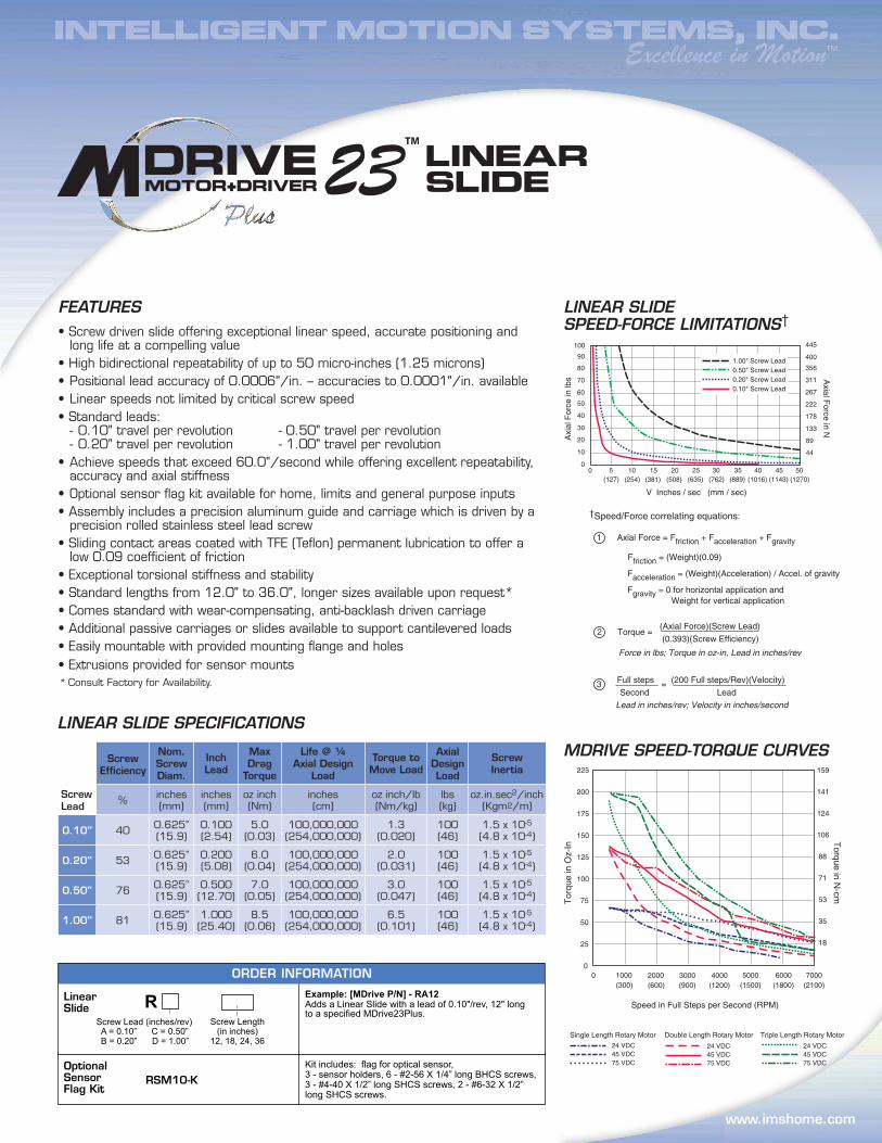
1.00" Screw Lead0.50" Screw Lead0.20" Screw Lead0.10" Screw Lead
V Inches / sec (mm / sec)
MDRIVE SPEED-TORQUE CURVES
LINEAR SLIDE SPEED-FORCE LIMITATIONS†
LinearSlide
TMExcellence in Motion
www.imshome.com
�� TM
�������������
2 Torque = (Axial Force)(Screw Lead)
Force in lbs; Torque in oz-in, Lead in inches/rev
(0.393)(Screw Effi ciency)
3 Full steps = (200 Full steps/Rev)(Velocity)
Lead in inches/rev; Velocity in inches/second Second Lead
†Speed/Force correlating equations:
1 Axial Force = Ffriction + Facceleration + Fgravity
Ffriction = (Weight)(0.09)
Facceleration = (Weight)(Acceleration) / Accel. of gravity
Fgravity = 0 for horizontal application and Weight for vertical application
Torq
ue in
Oz-
In
Torque in N-cm
Speed in Full Steps per Second (RPM)
0 1000 2000 3000 4000 5000 6000 7000(300) (600) (900) (1200) (1500) (1800) (2100)
75
50
25
150
125
100
225
200
175
0
88
106
71
141
159
124
53
35
18
24 VDC
Single Length Rotary Motor
45 VDC75 VDC
24 VDC
Double Length Rotary Motor
45 VDC75 VDC
24 VDC45 VDC
Triple Length Rotary Motor
75 VDC

E
D
A
C
B
P/N RSM10-K Includes: A #2-56 X 1/4" Long BHCS
B Sensor Holder (Qty. 3)
C #4-40 X 1/2" Long SHCS
D Flag for Optical Sensor
E #6-32 X 1/2" Long SHCS
Sensor Flag Kit Option
����������������������������������������������������
370 N. Main StreetP.O. Box 457Marlborough, CT 06447 U.S.A.Phone: 860/295-6102Fax: 860/295-6107E-mail: [email protected]
IMS MOTORS DIVISION 105 Copperwood Way, Suite H Oceanside, CA 92054 Phone: 760/966-3162 Fax: 760/966-3165 E-mail: [email protected]
U.S.A. SALES OFFICESEastern Region Phone: 862/208-9742 Fax: 973/661-1275 E-mail: [email protected] Region Phone: 260/402-6016 Fax: 419/858-0375 E-mail: [email protected] Region Phone: 408/472-1971 Fax: 408/268-0716 E-mail: [email protected]
ASIA PACIFIC OFFICE 30 Raffles Pl., 23-00 Caltex House Singapore 048622 Phone: +65/6233/6846 Fax: +65/6233/5044 E-mail: [email protected]
IMS EUROPE GmbH Hahnstrasse 10, VS-Schwenningen Germany D-78054 Phone: +49/7720/94138-0 Fax: +49/7720/94138-2 E-mail: [email protected] Sales Management 4 Quai Des Etroits 69005 Lyon, France Phone: +33/4 7256 5113 Fax: +33/4 7838 1537 E-mail: [email protected] Sales Phone: +49/35205/4587-8 Fax: +49/35205/4587-9 E-mail: [email protected]/UK Technical Support Phone: +49/7720/94138-0 Fax: +49/7720/94138-2 E-mail: [email protected]
IMS Product Disclaimer and most up-to-date product information available at www.imshome.com.© 2006 Intelligent Motion Systems, Inc. All Rights Reserved.
Distributed By:
TECHNICAL SUPPORTEastern U.S.A. Phone: 860/295-6102 Fax: 860/295-6107 E-mail: [email protected] U.S.A. Phone: 760/966-3162 Fax: 760/966-3165 E-mail: [email protected]/UK Phone: +49/7720/94138-0 Fax: +49/7720/94138-2 E-mail: [email protected]
www.imshome.com
MD
rive2
3P
lus
MD
rive2
3P
lus
REV020106
3.375(85.7)
2.22(56.4)
2.00(50.8)
0.36(9.2)0.56
(14.3)
0.626(15.9)2.336
(59.3)
1.000(25.4)
3.38(85.7)
1.23(31.1)0.688
(17.5)
L
OP
1.1(27.9)
1.250(31.8)
2.25(57.2)
4 x 1/4-20SHCS0.750
(19.1)
0.50(12.7)1.30
(33.0)
2.16(54.9)
3.25(82.6)1.560
(39.6)
2.6(66.0)
0.750(19.1)
1.50(38.1)
L
OP
1.1(27.9)
1.250(31.8)
2.25(57.2)
4 x 1/4-20SHCS0.750
(19.1)
0.50(12.7)1.30
(33.0)
2.16(54.9)
3.25(82.6)1.560
(39.6)
2.6(66.0)
0.750(19.1)
1.50(38.1)
MECHANICAL SPECIFICATIONSDimensions in Inches (mm)
1 Motor Mounting Plate
2 Heli-Cal Coupling
3 Sunx P/N PM-L24 sensor or equivalent (not supplied)
4 Optional Sensor Flag Kit for use with U-channel sensor (details below)
4
1
3
For reference only: 1/4-20 SHCS
Travel distance = L – (O + P) [O + P = 4.55" (115.6 mm)]
2
Optical sensor – Sunx P/N PM-L24 or equivalent(not supplied)