exercise 2-2 gearbox, coupling, and alignment - lab- · pdf filehigh-speed shaft coupling and...
TRANSCRIPT
© Festo Didactic 52070-00 99
When you have completed this exercise, you will be familiar with the high-speed part of the drive train system between the gearbox and the generator. More specifically, you will check gearbox temperature at rest and during operation, analyze vibration on the gearbox, change gearbox oil, and align the shafts.
The Discussion of this exercise covers the following points:
More information about the gearboxGear ratio. Oil. Temperature sensor. Fastening.
High-speed shaftCoupling and alignment with the generator. Alignment procedure.
More information about the gearbox
Gear ratio
You already know (as the names indicate) that the high-speed shaft runs faster than the low-speed shaft. In fact, the gearbox provides a ratio of 38.45 between these rotational speeds. Therefore, a low-speed shaft rotating at 47 RPM will drive the high-speed shaft at 1800 RPM.
An inductive sensor similar to that on the low-speed side is also located on the high-speed side and updates the number of rotations per minute (RPM) of the Gearbox Output Speed parameter on the main screen. Knowing these two angular speed values (displayed on the interface screen), the controller can verify that the speed ratio remains constant (i.e., at 38.45).
Oil
The trainer gearbox comes pre-filled with about 1.3 L (0.34 gal) of synthetic oil. A normal oil level should be around the middle of the see-through cover, like on Figure 2-46. Do not underfill or overfill the gearbox.
a Refer to Appendix G for oil specifications. Two types of oil (synthetic and mineral) are recommended. Be sure to use one or the other, but not both at the same time.
Gearbox, Coupling, and Alignment
Exercise 2-2
EXERCISE OBJECTIVE
DISCUSSION OUTLINE
DISCUSSION

Ex. 2-2 – Gearbox, Coupling, and Alignment Discussion
100 © Festo Didactic 52070-00
Figure 2-46. Normal oil level.
As with any oil, you may have to change it after a certain number of hours of operation if it changes color or appearance, or just for the sake of practicing the procedure since it is part of a training system.
a You may be asked to reuse the same oil or to use new oil, depending on your instructor’s choice.
Figure 2-47. Drain plug (left) and magnetic drain plug (right).
Take note that the drain plug of this gearbox may feature a magnet (as shown in Figure 2-47) to collect metallic residues so that they don’t circulate with the oil and cause damage to the gears. Should you change the oil, be sure to clean the plug to remove these residues. Also, make sure that you dispose of the used oil in a proper manner, in accordance with local regulations. This principle applies here in the classroom as well as in real life.
Beside the drain plug, other openings in the housing are:
A breather valve to equilibrate air pressure without letting dirt in. This is
also the oil filling opening.
A sight glass located just above normal oil level.
a It is pure luxury to have both a see-through cover and a sight glass to check the oil level. In many cases, you will only find a plug that you need to remove in order to evaluate the oil level.
Temperature sensor
A thermocouple is attached to the gearbox enclosure to provide feedback regarding the actual gearbox temperature at any time to maintain the system in reasonable conditions of operation. High oil temperature can cause damage just as serious as oil contamination does.
Oil level
Drain plug
See-through cover

Ex. 2-2 – Gearbox, Coupling, and Alignment Discussion
© Festo Didactic 52070-00 101
An offset can be added to the gearbox and generator temperature values through the Service screen (Figure 2-48). Unless otherwise specified, you should always leave these values at zero.
Figure 2-48. Temperature offset on the Service screen.
Fastening
The gearbox of your training system is shaft mounted. It is maintained in position by two elements: the low-speed shaft and the “torque arm bolt” (Figure 2-49). The low-speed shaft maintains the gearbox along its longitudinal axis while the torque arm bolt secures the gearbox in the remaining degree of freedom. The height of the gearbox is adjustable through the torque arm bolt.
Figure 2-49. The two gearbox anchors.
Gearbox oil temperature
elevation during operation is
a common phenomenon.
When surface cooling is not
sufficient, an additional
cooling system might be
required.
leave to zero
Torque arm bolt
Low-speed shaft

Ex. 2-2 – Gearbox, Coupling, and Alignment Discussion
102 © Festo Didactic 52070-00
High-speed shaft
The high-speed shaft of the trainer is solid, just like the low-speed shaft. In fact, the only hollow shaft on the system is the shaft inside the gearbox through which the low-speed shaft passes and to which it is fastened using a shrink disk (the same shrink disk that you accessed in Ex. 2-1).
Coupling and alignment with the generator
The nacelle trainer features the double disk coupling presented in Figure 2-50. It permits a maximum angular misalignment of 1.4° (0.7° per disc) when no radial or axial misalignment is present. The manufacturer table of tolerances is given in Appendix G for reference.
Figure 2-50. Disk brake and coupling.
Alignment procedure
The nacelle training system comes with a stylus indicator alignment kit (Figure 2-51). The procedure on how to align shafts using this kit is detailed in the exercise procedure to follow.
Figure 2-51. Stylus indicator alignment kit.
The arrangement of the high-speed shaft and disk brake does not allow for full rotation of the alignment kit. However, half-turn rotation permits sufficient accuracy for the application.

Ex. 2-2 – Gearbox, Coupling, and Alignment Procedure Outline
© Festo Didactic 52070-00 103
The Procedure is divided into the following sections:
Accessories needed
Basic safety procedure
Preparation question
Setting up the nacelleChecking gearbox oil level, quality, and possible spill.
Starting the trainer in automatic mode
Gearbox temperature at rest
Starting the wind simulationVibration on the nacelle. Gearbox temperature during active control.
Lockout/tagout
Gearbox oil changeFilling with some new, clean oil.
High-speed shaft and generator alignment
Result of the alignment
End of the procedure
Accessories needed
For this exercise, you will need the following accessories:
Lockout device (hasp)
One padlock and one tag per student
8 mm hex key (gearbox drain plug)
17 mm wrench (breather valve plug)
Black plastic bucket
Galvanized steel funnel with strainer
Rags (not included)
Alignment kit
Shims
Two 13 mm wrenches (high-speed inductive sensor)
Two 9/16” wrenches (alignment kit)
Two 3/4” wrenches (torque arm bolt, stylus points, and sight glass plug)
Two 1/2" wrenches (generator foot bolts)2
2 It is easier to use a wrench and a ratchet (not included) for the bolts of the generator.
PROCEDURE OUTLINE
PROCEDURE

Ex. 2-2 – Gearbox, Coupling, and Alignment Procedure
104 © Festo Didactic 52070-00
Basic safety procedure
Before using the training system, complete the following checklist:
You are wearing safety glasses and safety shoes.
You are not wearing anything that might get caught such as a tie,
jewelry, or loose clothes.
If your hair is long, tie it out of the way.
The working area is clean and free of oil or water.
Preparation question
1. Where is the gearbox thermocouple located?
Setting up the nacelle
2. Make sure the main switch is off and everything is secure inside and around the nacelle.
3. Open the safety panels and position the vibration sensor on the gearbox (Figure 2-52).
Never let the vibration sensor cable run near moving parts as it could get stuck and
become damaged.

Ex. 2-2 – Gearbox, Coupling, and Alignment Procedure
© Festo Didactic 52070-00 105
Figure 2-52. Vibration sensor on the gearbox.
Checking gearbox oil level, quality, and possible spill
4. Is the gearbox oil level similar to what you see in Figure 2-46?
Yes No
If not, ask your instructor if you should add/remove oil before starting the nacelle trainer.
5. Is the oil dark or black, indicating thermal decomposition or contamination?
Yes No
If yes, ask your instructor if you should change the oil before starting the nacelle trainer.
6. Do you observe any unusual oil leak in, around, or under the trainer?
Yes No

Ex. 2-2 – Gearbox, Coupling, and Alignment Procedure
106 © Festo Didactic 52070-00
7. If there is a leak, what is the possible origin of the leak? Do you suspect a particular seal?
8. If necessary, clean any spilled oil according to the procedure established in your classroom.
9. Close all safety panels.
Starting the trainer in automatic mode
10. Notify all the people working around the nacelle that the system is about to be energized and ask your instructor for permission to power the nacelle training system.
11. Turn on the main power switch. Wait for the HMI to boot and log into Windows. The HMI should start automatically.
12. Press the safety reset button.
13. Press Start Trainer in the HMI MAIN screen.
14. If the ALARMS button is flashing red at this point, press it. In the opening ALARMS screen, acknowledge each current alarm. Next, press RESET ALARMS, if necessary.
Gearbox temperature at rest
15. What is the gearbox temperature at this time, as indicated on the main screen?
Ex. 2-2 – Gearbox, Coupling, and Alignment Procedure
© Festo Didactic 52070-00 107
Starting the wind simulation
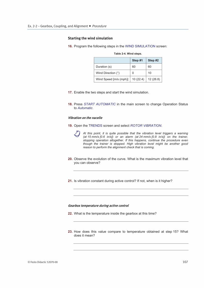
16. Program the following steps in the WIND SIMULATION screen:
Table 2-4. Wind steps.
Step #1 Step #2
Duration (s) 60 60
Wind Direction (°) 0 10
Wind Speed [m/s (mph)] 10 (22.4) 12 (26.8)
17. Enable the two steps and start the wind simulation.
18. Press START AUTOMATIC in the main screen to change Operation Status to Automatic.
Vibration on the nacelle
19. Open the TRENDS screen and select ROTOR VIBRATION.
a At this point, it is quite possible that the vibration level triggers a warning (at 15 mm/s [0.6 in/s]) or an alarm (at 24 mm/s [0.8 in/s]) on the trainer, stopping operation altogether. If this happens, continue the procedure even though the trainer is stopped. High vibration level might be another good reason to perform the alignment check that is coming.
20. Observe the evolution of the curve. What is the maximum vibration level that you can observe?
21. Is vibration constant during active control? If not, when is it higher?
Gearbox temperature during active control
22. What is the temperature inside the gearbox at this time?
23. How does this value compare to temperature obtained at step 15? What does it mean?
Ex. 2-2 – Gearbox, Coupling, and Alignment Procedure
108 © Festo Didactic 52070-00
24. Use the main power switch to turn all system power off.
Lockout/tagout
For the operations to follow, the nacelle needs to be secured first.
25. Install the lockout hasp in the main switch. Next, install the student padlocks and tags in the hasp.
26. Try to turn on the main switch to verify that the system is electrically isolated. Press the safety reset button to test whether the system can be energized.
a At this point, the system can be considered secure.
Gearbox oil change
Draining the old oil
27. Open the safety panels.
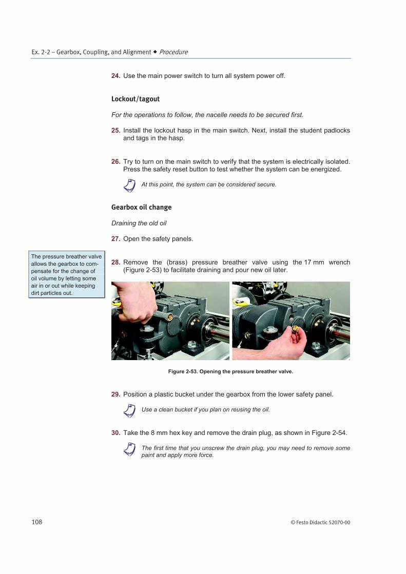
28. Remove the (brass) pressure breather valve using the 17 mm wrench (Figure 2-53) to facilitate draining and pour new oil later.
Figure 2-53. Opening the pressure breather valve.
29. Position a plastic bucket under the gearbox from the lower safety panel.
a Use a clean bucket if you plan on reusing the oil.
30. Take the 8 mm hex key and remove the drain plug, as shown in Figure 2-54.
a The first time that you unscrew the drain plug, you may need to remove some paint and apply more force.
The pressure breather valve
allows the gearbox to com-
pensate for the change of
oil volume by letting some
air in or out while keeping
dirt particles out.

Ex. 2-2 – Gearbox, Coupling, and Alignment Procedure
© Festo Didactic 52070-00 109
Figure 2-54. Removing the drain plug.
31. Let the “old” oil drain completely. This should take a couple of minutes. You may want to start the High-speed shaft and generator alignment procedure now while you are waiting for the oil to drain.
a If you change synthetic for mineral oil or vice versa, it is important keep the volume of old oil to a minimum to avoid mixing different types of oil.
Although it is not necessary here, keep in mind that it is sometimes required to flush the oil completely more than once when two oil types are highly incompatible.
32. Clean the drain plug, check the sealing element, and screw the plug back into place.
33. Either keep the “old” oil to reuse it later, or dispose of it in a manner discussed with your instructor.
Filling with some new, clean oil
34. Take the 3/4” wrench and remove the sight glass plug (Figure 2-55).

Ex. 2-2 – Gearbox, Coupling, and Alignment Procedure
110 © Festo Didactic 52070-00
Figure 2-55. Removing the sight glass plug.
35. Using the metal funnel, pour new (or “new”) oil into the gearbox through the breather valve opening. If you do not reuse the same oil, you will need approximately 1.3 L (0.34 gal) of oil. A filled gearbox will have oil up to the bottom of the sight glass plug.
a The strainer inside the metal funnel prevents residues from entering the gearbox.
Figure 2-56. Pouring new oil into the gearbox.
The sight glass plug is lo-
cated just above the normal
oil level.

Ex. 2-2 – Gearbox, Coupling, and Alignment Procedure
© Festo Didactic 52070-00 111
36. Verify that there is no oil leak around the drain plug.
37. Check the condition of the pressure breather valve and sight glass plug. Change their sealing element if necessary, and screw them back into place.
High-speed shaft and generator alignment
38. Prepare your tools for the alignment procedure.
39. (Optional – necessitates a feeler gauge) Check for soft foot and place shims under the faulty foot if necessary.
40. Uninstall the inductive sensor (Figure 2-57) using a pair of 13 mm wrenches.
Figure 2-57. Removing the sensor on the disk brake.
41. Release the parking brake manually. To do so, screw the knob of valve SV6 completely and then rotate the knob of valve SV4 by a quarter turn, as shown in Figure 2-58.
a A minimum pressure of 51.7 bar (750 psi) is required at port GB2 to release the brake. Use the hand pump to increase pressure if necessary. Figure 3-51 in Unit 3 shows how to use the hand pump.
Figure 2-58. Releasing the parking brake manually.

Ex. 2-2 – Gearbox, Coupling, and Alignment Procedure
112 © Festo Didactic 52070-00
42. Install one part of the kit on either side of the coupling as shown in Figure 2-59a. Insert the bolts in the bottom holes of the bracket and use the 9/16” wrenches to secure them.
Figure 2-59. Alignment kit positions.
43. One stylus can be moved vertically and the other one horizontally on the bracket. Align the styluses in both directions, and use the screws to move the styluses closer or farther apart until the points almost touch in the 0° position.
44. (Vertical plane angular misalignment) Rotate the shaft between the 0° and 180° positions. If the points move closer or farther apart (ignore vertical travel for now), this means there is angular misalignment (Figure 2-60). Place or remove shims under the front or back of the generator to reduce angular displacement by about half of the maximum separation distance.
Figure 2-60. Angular misalignment.
(a) 0 degrees (b) 90 degrees (c) 180 degrees

Ex. 2-2 – Gearbox, Coupling, and Alignment Procedure
© Festo Didactic 52070-00 113
45. Reposition the stylus points when the shaft is at the 0° position. Rotate the shafts and verify that the distance between styluses remains the same (ignore vertical travels for now). Repeat the previous step if necessary.
46. (Vertical plane parallel misalignment) Rotate the shaft between the 0° and 180° positions again. This time, correct the vertical offset (Figure 2-61) by moving the torque arm bolt up or down (Figure 2-62) or by placing shims under all four feet of the generator for an adjustment of about half of the observed offset.
Figure 2-61. Vertical offset.
a Use two 3/4" wrenches to adjust the torque arm bolt height (Figure 2-62).
Figure 2-62. Moving the torque arm bolt by rotating the two lower nuts.
Do not rotate the torque arm bolt or the top nut. Squeezing the black rubber washers may
damage them. Only rotate the bottom two nuts and hold the bolt in place if necessary to
modify the gearbox height. Do not forget to retighten the bottom nuts to avoid damage
next time the trainer is started.
(a) bottom nut rotation (bolt remains static)
(b) second nut rotation (bolt remains static)

Ex. 2-2 – Gearbox, Coupling, and Alignment Procedure
114 © Festo Didactic 52070-00
47. Reposition the stylus points when the shaft is at the 0° position. Rotate the shafts and verify that the vertical distance remains minimal. Repeat the previous step if necessary. If the points move closer or farther apart, this is a sign of angular misalignment and you may need to repeat step 44.
48. (Horizontal plane misalignment) Rotate the shaft between the 0° and 90° positions. Correct for any angular offset (Figure 2-63) by loosening the generator bolts and slowly moving the generator sideways. Retighten the bolts.
Figure 2-63. Horizontal offset (view from the top).
49. Reposition the stylus points when the shaft is at the 0° position. Rotate the shafts and verify that the horizontal distance remains minimal. Repeat the previous step if necessary.
50. Rotate the shaft between the 0°, 90°, and 180° positions once more and verify that no angular or parallel misalignment remains. Repeat appropriate procedure steps if necessary. Record any relevant observations such as major difficulties or remaining misalignment.
51. Remove the alignment kit and reinstall the inductive sensor at the top of the slot. The distance between the sensor and the perforated disk should be about 3 mm (0.12 in).
a If you install the sensor at the bottom of its slot, the sensor will detect only half of the perforations it should normally detect. This will generate an error next time the nacelle operates in automatic mode.

Ex. 2-2 – Gearbox, Coupling, and Alignment Conclusion
© Festo Didactic 52070-00 115
52. Return the manual overrides of valves SV4 and SV6 to their original position and verify that the brake is on.
53. Close the safety panels.
Result of the alignment
54. Ask everyone to remove their individual padlock and tag. Next, remove the hasp from the main switch.
55. Restart the trainer and compare the vibration level to what you had before the alignment. Tell your instructor about any unusual situation. Note your observations below.
56. Have you succeeded in diminishing the vibration level?
Yes No
End of the procedure
57. Perform a final system shutdown.
58. Clean the area and, more specifically, the bucket, and the funnel that were used to change the gearbox oil.
In this exercise, you became familiar with the high-speed part of the drive train system between the gearbox and the generator. More specifically, you checked gearbox temperature at rest and during operation, analyzed vibration on the gearbox, changed the gearbox oil, and aligned the shafts.
1. When should you change the oil of a gearbox?
2. What are the two elements supporting the gearbox on the nacelle training system?
CONCLUSION
REVIEW QUESTIONS

Ex. 2-2 – Gearbox, Coupling, and Alignment Review Questions
116 © Festo Didactic 52070-00
3. What is the speed of the high-speed shaft of the training system if the low-speed shaft is running at 40 RPM?
4. Why is there a thermocouple attached to the gearbox?
5. Which type of misalignment is corrected by placing shims under the front feet of the generator?