exhaust emission catalyst technology · exhaust emission catalyst technology new challenges and...
TRANSCRIPT
Exhaust Emission Catalyst Technology NEW CHALLENGES AND OPPORTUNITIES IN EUROPE
By Dirk Bosteels and Robert A. Searles Association for Emissions Control by Catalyst, Av. de Tervueren 100, 6-1040 Brussels, Belgium; (www.aecc.be)
New technologies, incorporating the platinum group metals, are available to meet the exhaust emission regulations for cars, light-duty and heavy-duty vehicles and motorcycles being adopted by the European Union for implementation during the new century. These technologies include low light-off catalysts, more themlly-durable catalysts, impmved substrate technology, hydrocarbon adsorbers, electrically heated catalysts, DeNOx catalysts and adsorbers, selective catalytic reduction and diesel particulate filters. This large range of technologies will allow exhaust emissions from all engines, both on- and non-road, to be lowered to unprecedented levels. This paper examines the state of emission control technologies currently available for all types of engine.
Catalyst-equipped cars were fist introduced in the U.S.A. in 1974 (1) but only appeared on
European roads in 1985. Indeed, it was not until 1993 that the European Union (ELI) set new car emission standards that effectively mandated the installation of emission control catalysts on gaso- he-fuelled cars. Worldwide, now more than 275 million of the world's 500 million cars and over 85 per cent of all new cars produced are equipped with autocatalysts.
In the EU directives are being adopted to leg- islate the maximum exhaust emissions permitted from a wide range of vehicles and equipment pow- ered by the internal combustion engine. Exhaust emission catalyst technology is increasingly being fitted on heavy-duty vehicles, buses, motorcycles and on non-road engines and vehicles. The 13 candidate countries currently negotiating entry to the EU (including Poland, Hungary and the Czech Republic) d, as a result of adopang the limit val- ues of the EU, increase the application of the technologies developed to control emissions in the EU.
European Union Exhaust Emission and Fuel Legislation
The final report of the European Auto Oil II programme (2) concluded that some ait quality problems, such as atmospheric levels of particulate matter (PM) and ozone, are not yet solved. The
challenge is to abate the remaining pollutants emit- ted while enabhg use of fuel-efficient engine technologies. This is paramount for achieving good air quality and the targets for greenhouse gas reductions given the large increase in the number of vehicles on European roads, the projections for further increases in vehicle numbers and the greater distances driven each year.
Emissionsfmm On-Road Vehickr The EU emission limits for passenger cars that
came into effect from 1993 were lowered in 1996 and again in 2000. For passenger cars (Tables I and Il) and hght commercial vehicles the emission standards have been agreed for 2000 and 2005 (3). Lght commercial vehicle limit values are adjusted to compensate for the &her vehicle weights.
Heavy-duty diesel (HDD) vehicles have new test cycles and tougher emission standards finalised for 2000 and 2005. The limit values for enhanced environmentally friendly vehicles (EEVs) are set to serve as a basis for fiscal incen- tives by EU Member States. The 2005 (Euro W) emission standards set limit values for carbon monoxide (CO) (1.5 g/kWh), hydrocarbons (HCs) (0.46 g/kWh) and nitrogen oxides (NOx) (3.5 g/kWh) and also PM limit values intended to force the use of particulate traps/diesel particulate filters (DPFs). The PM limits are 0.02 g/kWh on the steady state cycle (ESC) and 0.03 g/kWh on the
Phtinwnr Met& Rev., 2002,46, (I), 27-36 27
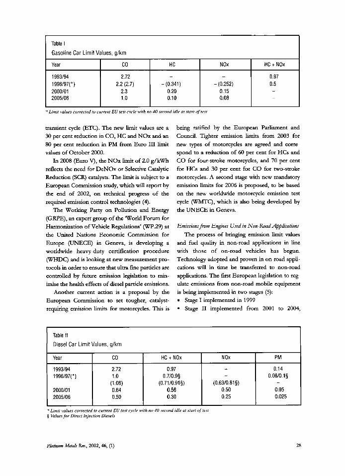
Table I
Gasoline Car Limit Values, g/km
Year
1993/94 1996/97( * ) 2000/01 2005/06
co HC NOx HC t NOx
2.72 0.97 2.2 (2.7) - (0.341) - (0.252) 0.5
2.3 0.20 0.15 - 1 .o 0.10 0.08 -
- -
transient cycle (ETC). The new limit values are a 30 per cent reduction in CO, HC and NOx and an 80 per cent reduction in PM from Euro III limit values of October 2000.
In 2008 (Euro V), the NOx limit of 2.0 g/kWh reflects the need for DeNOx or Selective Catalytic Reduction (SCR) catalysts. The limit is subject to a European Commission study, which will report by the end of 2002, on technical progress of the required emission control technologies (4).
The Working Party on Pollution and Energy (GRPE), an expert group of the World Forum for Harmonization of Vehicle Regulations’ (WP.29) at the United Nations Economic Commission for Europe (UNECE) in Geneva, is developing a worldwide heavy-duty certification procedure (WHDC) and is loow at new measurement pro- tocols in order to ensure that ultra h e particles are controlled by hture emission legislation to mir- imise the health effects of diesel patticle emissions.
Another current action is a proposal by the European Commission to set tougher, catalyst- requiring emission limits for motorcycles. This is
Year co HC t NOx NOx
1993194 2.72 0.97 - 1996/97( *) 1 .o 0.7/0.9§ -
2000101 0.64 0.56 0.50 2005106 0.50 0.30 0.25
(1.06) (0.71/0.91§) (0.63/0.81§)
being ratified by the European Parliament and Council. Tighter emission limits from 2003 for new types of motorcycles are agreed and corre- spond to a reduction of 60 per cent for HCs and CO for four-stroke motorcycles, and 70 per cent for HCs and 30 per cent for CO for two-stroke motorcycles. A second stage with new mandatory emission limits for 2006 is proposed, to be based on the new worldwide motorcycle emission test cycle 0, which is also being developed by the UNECE in Geneva.
PM
0.14 0.0810.1 0
0.05 0.025
-
Emissions from Engines Used in Nan-Road Applications The process of bringing emission limit values
and fuel quality in non-road applications in line with those of on-road vehicles has begun. Technology adopted and proven in on-road appli- cations will in time be transferred to non-road applications. The first European legislation to reg- ulate emissions from non-road mobile equipment is being implemented in two stages (5):
Stage I implemented in 1999 Stage I1 implemented from 2001 to 2004,
Phtintm Metuh h., 2002,46, (1) 28
' Limit values corrected to current EU test cycle with no 40 second idle at start of test
Table II Diesel Car Limit Values, g/km
Limit vulues corrected to currenr EU test cycle with no 40 second idle at starr oftest Values .for Direct Injection Diesels

Table Ill
EU Emission Limits for Non-Road Diesel Engines, g/kWh
6.0 6.0 7.0 8.0
Net Power
0.2 0.3 0.4 0.8
Stage I 130-560 kW 75-1 30 kW 37-75 kW
Stage II 130-560 kW 75-1 30 kW 37-75 kW 18-37 kW
NOx I PM
9.2 9.2 9.2
0.54 0.70 0.85
dependmg on the engine power output. The equipment covered indudes mobile con-
struction machinery, forklift trucks, road maintenance equipment, ground support equip- ment in airports, aedal lifts and mobile cranes. Agricultural and forestry tractors have the same emission standards but with different implementa- tion dates (6). Engines used in ships, railway locomotives, aircraft, and generating sets, not yet covered by the directive, are being considered by a
Commission working group and will be included in the future.
Stages I and I1 are based on a steady-state 8- mode test procedure, and emission limit values are shown in Table 111.
Values for the Stage 111 limits using a new tran- sient test procedure (NRTC) are under discussion in a European Commission working group. The intention is to develop global solutions and to develop the legislation in dose cooperation with the U.S.A. and Japan, using the global agreement under UNECE in Geneva as the basis for legisla- tion.
A European Commission Task Force has been set up to improve the fuel quality for non-road applications. Reducing sulfur content in non-road fuels in line with those being introduced in the road sector would allow engine makers to use the advanced emission control technologies of cata- lysts and traps to reduce gaseous and particulate emissions. A Commission proposal was issued at the end of 2000 (7) and established the first
emission limits for small spark-ignition engines below 19 kW used in lawn mowers, chain saws, bush cutters, trimmers and snow removal equip- ment. The proposal, which is now being considered by the European Parliament and Council, has been developed in cooperation with the US. Environmental Protection Agency in a move toward worldwide harmonisation.
The proposal indudes two stages of limit val- ues: the first to be met 18 months after the directive comes into force and the second one between 2004 and 2010 dependmg on the catego- ry of the engine. The second stage will lower emissions from handheld engines by about 80 to 85 per cent.
Gasoline and diesel engines installed in recre- ational crafts and personal watercrafts are already subject to some emission and noise requirements and limits (8). The European Commission pro- posed amendments in October 2000 to the current directive, fuaher reducing the exhaust pollutants.
Fuels The mandatory standards for fuel sul fur levels
for on-road fuels were set in 1998 (9). However after a full technical study the European Commission adopted a proposal in May 2001 to require the introduction of sulfur-free (< 10 ppm) gasoline and diesel by each EU Member State from 1 January 2005. Under the proposal, sti l l to be ratified, gasoline and diesel fuel with ‘a sulfur content’ would be banned from the EU market
Phtimm~ Mefa? Rm, 2002,46, (1) 29
co I HC
5.0 5.0 6.5
1.3 1.3 1.3
3.5 5.0 5.0 5.5
1 .o 1 .o 1.3 1.5
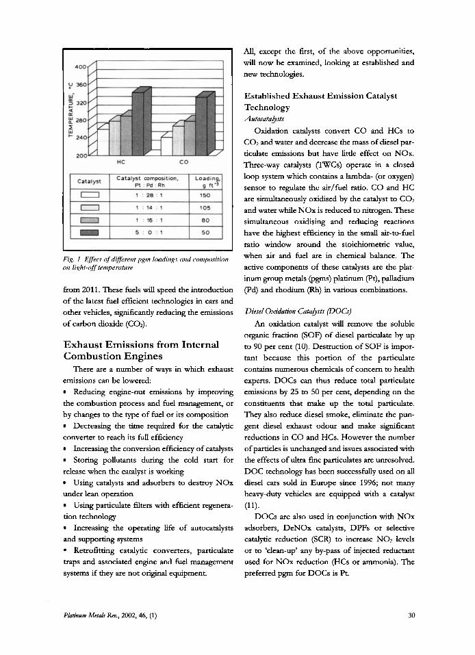
Fig. I Effect of different pgm loadings mid cornposition 011 light-off temperature
from 201 1. These fuels will speed the introduction of the latest fuel-efficient technologies in cars and other vehicles, significantly reducing the emissions of carbon dioxide (COZ).
Exhaust Emissions from Internal Combustion Engines
There are a number of ways in which exhaust emissions can be lowered:
Reducing engine-out emissions by improving the combustion process and fuel management, or by changes to the type of fuel or its composition
Decreasing the time required for the catalytic converter to reach its full efficiency
Increasing the conversion efficiency of catalysts Storing pollutants during the cold start for
release when the catalyst is working Using catalysts and adsorbers to destroy NOx
under lean operation Using particulate filters with efficient regenera-
tion technology Increasing the operating life of autocatalysts
and supporting systems Retrofitting catalytic converters, particulate
traps and associated engine and fuel management systems if they are not original equipment.
All, except the first, of the above opportunities, will now be examined, looking at established and new technologies.
Established Exhaust Emission Catalyst Technology AutocatahJtts
Oxidation catalysts convert CO and HCs to COZ and water and decrease the mass of diesel par- ticulate emissions but have little effect on NOx. Three-way catalysts W C s ) operate in a closed loop system which contains a lambda- (or oxygen) sensor to regulate the &/fuel ratio. CO and HC are simultaneously oxidised by the catalyst to COZ and water while NOx is reduced to nitrogen. These simultaneous oxidising and reducing reactions have the highest efficiency in the small air-to-fuel ratio window around the stoichiometiic value, when air and fuel are in chemical balance. The active components of these catalysts are the plat- inum group metals (pgms) platinum (Pt), palladium (Pd) and rhodium (Rh) in various combinations.
Diesel Oxihtion Cata!ysfJ (DOCS) An oxidation catalyst will remove the soluble
organic fraction (SOF) of diesel particulate by up to 90 per cent (10). Destruction of SOF is impor- tant because this portion of the particulate contains numerous chemicals of concern to health experts. DOCs can thus reduce total particulate emissions by 25 to 50 per cent, depending on the constituents that make up the total particulate. They also reduce diesel smoke, eliminate the pun- gent diesel exhaust odour and make significant reductions in CO and HCs. However the number of particles is unchanged and issues associated with the effects of ultra-fine particulates are unresolved. DOC technology has been successfully used on all diesel cars sold in Europe since 1996; not many heavy-duty vehicles are equipped with a catalyst
DOCs are also used in conjunction with NOx adsorbers, DeNOx catalysts, DPFs or selective catalytic reduction (SCR) to increase NO2 levels or to ‘clean-up’ any by-pass of injected reductant used for NOx reduction (HCs or ammonia). The preferred pgm for DOCs is Pt.
(11).
PLatinum Metah Kev., 2002, 46, (1) 30
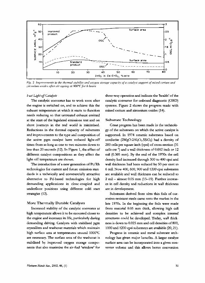
Fig. 2 Imn~~r~i~~entents to the thermal stahiliry cmd oxygen storage capmi8 v j 'c i ccitolyst support of mixed cerium and :irconiurn o.i-ides ufirr air Ngeiiig at 900%,for 6 hours
Fast Lgbt-off Catahsts The catalytic converter has to work soon after
the engine is switched on, and to achieve this the exhaust temperature at which it starts to function needs reducing so that untreated exhaust emitted at the start of the legislated emissions test and on short journeys in the real world is minimised. Reductions in the thermal capacity of substrates and improvements to the type and composition of the active pgm catalyst have reduced light-off times from as long as one to two minutes down to less than 20 seconds (12). In Figure 1, the effect of different catalyst compositions as they affect the light-off temperature are shown.
The introduction of a new generation of Pt/Rh technologies for current and future emission star- dards is a technically and commercially amactive alternative to Pd-based technologies for high demanding applications in close-coupled and underfloor positions using different cold start strategies (13).
More Thermally Durable Catalysts Increased stability of the catalytic converter at
high temperature allows it to be mounted closer to the engine and increases its life, particularly during demanding driving. Catalysts with stabilised pgm crystallites and washcoat materials which maintain high surface area at temperatures around 1000°C are necessary. The surface area of the washcoat is stabilised by improved oxygen storage compo- nents that also maximise the air-fuel 'window' for
three-way operation and indicate the 'health' of the catalytic converter for onboard diagnostic (OBD) systems. Figure 2 shows the progress made with mixed cerium and zirconium oxides (14).
Substrate Technology Great progress has been made in the technolo-
gy of the substrates on which the active catalyst is supported. In 1974 ceramic substrates based on cordierite (2Mg0.W203.5SiO$ had a density of 200 cells per square inch (cpsi) of cross-section (31 cells cm-7 and a wall thickness of 0.012 inch or 12 mil (0.305 mm). By the end of the 1970s the cell density had increased through 300 to 400 cpsi and wall thickness had been reduced by 50 per cent to 6 mil. Now 400,600,900 and 1200 cpsi substrates are available and wall thickness can be reduced to
2 mil - almost 0.05 mm (15-19). Further increas- es in cell density and reductions in wall thickness are in development.
Substrates derived from ultra thin foils of cor- rosion-resistant steels came onto the market in the late 1970s. In the beginning the foils were made from material 0.05 mm thick, allowing high cell densities to be achieved and complex internal structures could be developed. Today, wall thick- ness is down to 0.025 mm and cell densities of 800, 1000 and 1200 cpsi substrates are available (20,21).
Progress in ceramic and metal substrate tech- nology has given major benefits. A larger catalyst surface area can be incorporated into a given con- verter volume and this allows better conversion
Pkatinnm MetaLr Rm, 2002, 46, (1) 31
efficiency and durability. The thin walls reduce thermal capacity and avoid the penalty of increased pressure losses. Alternatively the same perfor- mance can be incorporated into a smaller converter volume, which, as cars become more compact, makes the catalyst easier to fit close to
the engine.
New Technologies for Exhaust Emissions Control Stoichiometric Combustion Hydrocarbon Adsorbers
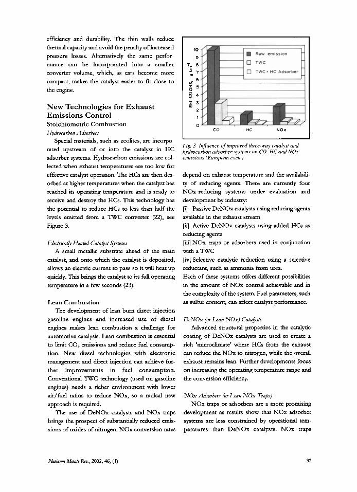
Special materials, such as zeolites, are incorpo- rated upstream of or into the catalyst in HC adsorber systems. Hydrocarbon emissions are col- lected when exhaust temperatures are too low for effective catalyst operation. The HCs are then des- orbed at higher temperatures when the catalyst has reached its operating temperature and is ready to
receive and destroy the HCs. This technology has the potential to reduce HCs to less than half the levels emitted from a TWC converter (22), see Figure 3.
El'ectvicalh Heated Catahst .$terns A small metallic substrate ahead of the main
catalyst, and onto which the catalyst is deposited, allows an electric current to pass so it will heat up quickly. This brings the catalyst to its full operating temperature in a few seconds (23).
Lean Combustion The development of lean bum direct injection
gasoline engines and increased use of diesel engines makes lean combustion a challenge for automotive catalysis. Lean combustion is essential to limit CO:! emissions and reduce fuel consump- tion. New diesel technologies with electronic management and direct injection can achieve fur- ther improvements in fuel consumption. Conventional TWC technology (used on gasoline engines) needs a richer environment with lower &/fuel ratios to reduce NOx, so a radical new approach is required.
The use of DeNOx catalysts and NOx traps brings the prospect of substantially reduced emis- sions of oxides of nitrogen. NOx conversion rates
1 0
9
7 8 E 1 7 m
6 vi 5 5
$ 4 I 3 w
2
1
0 co HC NOx
I
Fig. 3 Influence of improved three-wuy catalyst and hydrocurbon udsorber systems on CO, HC and NOx emissions (European cycle)
depend on exhaust temperature and the availabili- ty of reducing agents. There are currently four NOx-reducing systems under evaluation and development by industry: [i] Passive DeNOx catalysts using reducing agents available in the exhaust stream [i] Active DeNOx catalysts using added HCs as reducing agents [iii] NOx traps or adsorbers used in conjunction with a TWC [iv] Selective catalytic reduction using a selective reductant, such as ammonia from urea. Each of these systems offers different possibilities in the amount of NOx control achievable and in the complexity of the system. Fuel parameters, such as sulfur content, can affect catalyst performance.
D e N O x (or L a n N O x ) Cata& Advanced sa~ctural properties in the catalytic
coating of DeNOx catalysts are used to create a rich 'microclimate' where HCs from the exhaust can reduce the NOx to nitrogen, while the overall exhaust remains lean. Further developments focus on increasing the operating temperature range and the conversion efficiency.
N O x Adsorbers (or Lean N O x Traps) NOx traps or adsorbers are a more promising
development as results show that NOx adsorber systems are less constrained by operational tem- peratures than DeNOx catalysts. NOx traps
Phtinum Metah REP., 2002,46, (1) 32

adsorb and store NOx under lean condi- tions. A typical approach is to speed up the conversion of nimc oxide (NO) to nitrogen dioxide (NO,) using a pgm-containing oxi- dation catalyst or TWC mounted close to the engine so that NO2 can be rapidly stored as nitrate. The function of the NOx storage element can be fulfilled by materials that are able to form sufficiently stable nitrates with- in the temperature range determined by the lean operation regime of a direct injection gasoline engine. Thus especially alkaline, alkaline earths and, to a certain extent, also
rare earth compounds can be used. When this storage media nears capacity it
must be regenerated. This is accomplished in a NOx regeneration step. Unfortunately, alkaline and alkaline earth compounds have a strong affinity for sulfation. As a conse- quence alkaline and alkaline earth compounds are almost irreversibly poisoned by the sulfur contained in the fuel during the
mode, leading to a
decrease in adsorption dur- the Pr catdvst, to produce NOr which is them adsorbed. Lower ing operation. The stored NOx is released
Fig. 4 The working principle of rhe NOx adsorber: Upper diagram: under lean (low fuel) conditions, NO reucrs with 02 on
diagrurn: under rich (high fuel) conditions
by creating a rich atmosphere with injection of a small amount of fuel. The rich running por- tion is of short duration and can be accomplished in a number of ways, but usually includes some combination of intake air throthg, exhaust gas recirculation, late ignition tirmng and post com- bustion fuel injection. The released NOx is quickly reduced to N2 by reaction with CO (the same reac- tion that occurs in a TWC for spark-ignited engines) on a Rh catalyst site or on another pgm catalyst that is also incorporated into this unique single catalyst layer (Figure 4).
Thermal dissociation of the alkaline and aka- line earth sulfates, under oxygen-rich conditions, would require temperatures above 1000°C. Such temperatures cannot be achieved under realistic driving conditions. However, it has been demon- strated that it is possible to decompose the corresponding alkaline earth sulfates under reduc- ing exhaust and elevated temperature conditions to restore the NOx storage capacity (24-26). The necessary catalyst heating, for example by late igni-
tion timing, results in a considerable increase in fuel consumption, dependent upon the sulfur con- tent. Reducing fuel sulfur levels is the best way of using the full fuel economy and CO, reduction potential of modern direct injection gasoline engines.
Developments and optimisation of NOx adsorber systems are currently underway for diesel and gasoline engines. These technologies have demonstrated NOx conversion efficiencies rang- ing from 50 to in excess of 90 per cent, depending on the operaang temperatures and system respon- siveness, as well as fuel sulfur content (27,28). The system is in production with direct injection gaso- line engines.
Sehctive Catabiic Reduction (Sa) SCR technology has been used successfully for
more than two decades to reduce NOx emissions from power stations fired by coal, oil and gas, from marine vessels and stationary diesel engines.
Phtinnm Mefdr Rev., 2002,46, (1) 33
NOx storTage operation mode, NOx adsorption efficiency
SCR technology for HDD vehicles has been developed to the commercialisation stage and was available as an option in the series production of several European truck-manufacturing companies in 2001.
SCR technology permits the NOx reduction reaction to take place in an oxi- dising atmosphere. It is called ‘selective’ because the catalytic reduction of NOx with ammonia as a reductant occurs prefer- entially to the oxidation of ammonia with oxygen. Several types of catalyst are used and the temperature of the exhaust envi- Ionment determines the choice. For mobile source applications the preferred
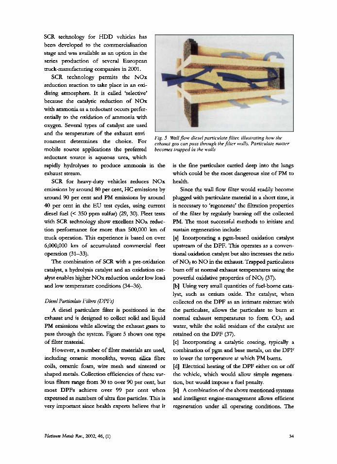
Fig. 5 Wall flow diesel partirulute filteK illustrating how the exhausi gas can puss through thefilter walls. Particulate matter becomes trapped in the walls
reductant source is aqueous urea, which rapidly hydrolyses to produce ammonia in the exhaust stream.
SCR for heavy-duty vehicles reduces NOx emissions by around 80 per cent, HC emissions by around 90 per cent and PM emissions by around 40 per cent in the EU test cycles, using current diesel fuel (< 350 ppm sulfur) (29, 30). Fleet tests with SCR technology show excellent NOx reduc- tion performance for more than 500,000 km of ttuck operation. This experience is based on over 6,000,000 km of accumulated commercial fleet operation (31-33).
The combination of SCR with a pre-oxidation catalyst, a hydrolysis catalyst and an oxidation cat- alyst enables higher NOx reduction under low load and low temperature conditions (34-36).
Diesel Particuhte Filtets (DPFs) A diesel particulate filter is positioned in the
exhaust and is designed to collect solid and liquid PM emissions while allowing the exhaust gases to pass through the system. Figure 5 shows one type of filter material.
However, a number of filter materials are used, i n c l u w ceramic monoliths, woven silica fibre coils, ceramic foam, wire mesh and sintered or shaped metals. Collection efficiencies of these var- ious filters range from 30 to over 90 per cent, but most DPFs achieve over 99 per cent when expressed as numbers of ultra fine particles. This is very important since health experts believe that it
is the fine particulate carried deep into the lungs which could be the most dangerous size of PM to health.
Since the wall flow filter would readily become plugged with particulate material in a short time, it is necessary to ‘regenerate’ the filtration properties of the filter by regularly burning off the collected PM. The most successful methods to initiate and sustain regeneration include: [a] Incorporating a pgm-based oxidation catalyst upstream of the DPF. This operates as a conven- tional oxidation catalyst but also increases the ratio of NO2 to NO in the exhaust. Trapped particulates bum off at normal exhaust temperatures using the powerful oxidative properties of NOz (37). [b] Using very small quantities of fuel-borne cata- lyst, such as cerium oxide. The catalyst, when collected on the DPF as an intimate mixture with the particulate, allows the particulate to bum at
normal exhaust temperatures to form COz and water, while the solid residues of the catalyst are retained on the DPF (37). [c] Incorporating a catalytic coating, typically a combination of pgm and base metals, on the DPF to lower the temperature at which PM bums. [d] Electrical heating of the DPF either on or off the vehicle, which would allow simple regenera- tion, but would impose a fuel penalty. [el A combination of the above mentioned systems and intelhgent engine-management allows efficient regeneration under all operating conditions. The
Pbtinwnr Metah Rev., 2002, 46, (1) 34
first diesel passenger cat equipped with a com- bined filter system was commercialised in 2000 and evaluations indicate a good and durable per- formance of the system. The system has now been extended to other models (39,40).
Continuously regeneraw DPFs are very suc- cessful in retrofit applications of older HDD vehicles and buses in various regions over the world. Real world durability of these systems is
particles into the atmosphere. Urea-based SCR systems and DPFs with an appropriate regenera- tion strategy are anticipated to be used on the next generation HDD engines and to show significant reductions of both NOx and PM (4547).
Conclusions There is thus a wide range of gaseous and par-
ticulate emission control options based on the use proven every day in major cities in Europe and the of catalytic, adsorption and trapping technologies, U.S.A. (4143). With any catalyst/DPF combina- with the pgms playing an essential role. don which includes pgms the use of diesel fuel Retrofitting of catalyst systems and particulate having a sulfur content lower than 10 ppm is nec- traps is increasing in response both to fiscal incen- essary to keep the formation of sulfate particulates tive schemes introduced by governments and to within future legislated limits (44). meet the requirements of environmental zones,
particularly in cities. Europe has a strong automo- Combined Emission ConhL Systems (DPF + SCR) tive emissions control industry well placed to help
A combined emission control system is an meet the challenge of future emission regulations attractive proposition; this is because of the strin- by worlung with its partners in the automotive gent emission limit values for NOx and PM set for industry. Advanced catalyst and trap systems, HDD engines in 2005 and 2008, the demands by together with optimised engine management and the transport sector for minimum fuel consump- emission controls can aid the achievement of the don of the engine and the political, public and future low emission standards deemed necessary health concerns over the emission of ultra h e to meet air quality goals.
References
1 B. I. Bertelsen, PIatinrrm Metah h., 2001,45, (2), 50
2 ‘A Review of the Auto-Oil I1 Programme’, COM(2000) 626, Commission of the European Communities, Brussels, 05.10.2000
350, Vol. 41,28 Dec. 1998; Directive 98/69/EC
1999/96/EC, 13 Dee. 1999
12 R J. Brisley etal , ‘The use of palladium in advanced catalysts’, SAE 950259
13 J. Schmidt et al, ‘Utilization of advanced Pt/Rh TWC technologies for advanced gasoline applica-
of the communities, tions with different cold s t a r t strategies’, SAE
14 J.-P. Cuif et al, ‘(Ce, 2r)OZ solid solutions for three way catalysts’, SAE 970463
15 S. T. Gulati, ’Thin wall ceramic catalyst supports’, SAE 1999-01-0269
2001 -01 -0927
5 European Directive 97/68/EC, 16 Dec. 1997
6 European Diiective 2000/25/EC, 22 May 2000
7 Commission proposal to amend European Directive 97/68/EC, COM(2000)840, Commission of the European Communities, Brussels, 18.12.2000
8 European Directive 94/25/EC, in force 16 June 1998
9 Of f id Journal of the European Communities, L 350, Vol. 41,28 Dec. 1998; Directive 98/70/EC
10 M. Horiucbi, S. Makoto, K. Saito and S. Ichihara, The effects of flow-through type oxidation catalysts on the particulate reduction of 1990s diesel engines’, SAE 900600
11 K. Voss et al, ‘Zirconia-based ceramic, in-cylinder coatings and aftertreatment oxidation catalysts for reduction of emissions from heavy-duty diesel engines’, SAE 970469
16 J. Sduni t t e t al, ‘The impact of hgh cell density ceramic substrates and washcoat properties on the catalytic activiq of three way catalysts’, SAE 1999- 01-0272
17 S. &chi e t al, Technology for reducing exhaust gas emissions in zero emission level vehicles’, SAE 1999-01-0772
18 S. T. Gulati, ‘Design considerations for advanced ceramic catalyst supports’, SAE 2000-01-0493
19 K. Nishizawa eta/., ‘New technologies targeting zero emissions for gasoline engines’, SAE 2000-01-0890
20 R Briick et al, The necessity of optimizing the inter- actions of advanced post-treatment components in order to obtain compliance with SULEV-legisla- tion’, SAE 1999-01-0770
Phinwn Mctah b., 2002, 46, (1) 35
3 Official Journal of the European Communities
4 European Directive
L

21
22
23
24
25
26
27
28
29
30
31
32
33
34
W. Maus, R Briick and G. Holy, ‘Zukiinftige abgas- nachbehandlungstechnologien k Otto-Motoren; Die nachste generation niedrigstemissions- fahrzeuge’, AVL Congress, Graz, Austria, Sept. 1999
N. Noda, A. Takahashi, Y. Shibagaki and H. Mizuno, ‘In-line hydrocarbon adsorber for cold start emissions - Part 11’, SAE 980423
F. J. Hanel, E. Otto, R Briick, T. Nagel and N. Bergaul, ‘Practical experience with the EHC system in the BMW ALPINA B12’, SAE 970263
W. Strehlau, J. Leyrer, E. S. Lox, T. Kreuzer, M. Hori and M. Hoffmann, ‘New developments in lean NOx catalysis for gasoline fuelled passenger cars in Europe’, SAE 962047
M. S. Brogan, R J. Brisley, A. P. Walker, D. E. Webster, W. Boegner, N. P. Fekete, M. Kraemer, B. Krutzsch and D. Voigtlaender, ‘Evaluation of NOx storage catalysts as an effective system for NOx removal from the exhaust gas of lean bum gasoline engines’, SAE 952490
U. Gobel, T. Kreuzer and E. S. Lox, ‘Moderne NOx-adsorber-technologien, grundlagen, vorausset- zungen, e r f h g e n ’ , Proc. VDA-Conf., Frankfurt, 1999
H. Liiders, P. Stommel and S. Geckler, ‘Diesel exhaust treatment - New approaches to ultra low emission diesel vehicles’, SAE 1999-01-0108
N. Ruzicka and T. Liebscher, ‘Possible aftemeat- ment concepts for passenger car diesel engines with sulphur-free fuel’, SAE 1999-01-1328
S. Fischer, L. Hofmann and W. Mathes, The devel- opment of the SINOx system for commercial vehicles for serial applications’, 20th Vienna Motor Syrflposium, 6 7 May, 1999, VDI Fortschritts- benchte Reihe 12, Nr. 376,267-282
B. Amon, S. Fischer, L. Hofmann and J. Zuerbig, ‘The SINOx system for trucks to fulfil the future emission regulations’, CAPoC 5, Brussels, 12-14 April, 2000
Siemens AG and Automotive, ‘Investigation on long-term stability of diesel DeNOx catalyst exhaust gas aftertreatment systems on 3 MAN and 10 DaimlerChrysler trucks - results of the 2nd Bavarian Road Test’, Final Report
N. Fritz, W. Mathes, J. Ziirbig and R. Mueller, ‘On- road demonstration of NOx emission control for diesel trucks with SINOx urea SCR system’, SAE 1999-01-01 11
W. MiUer, J. Klein, R Mueller, W. Doelling and J. Ziirbig, ‘The development of urea-SCR technology for US. heavy-duty trucks’, SAE 2000-01-0190
E. Jacob, G. Emmerling, A. Doring, U. Graf, M. Harris, J. van den Tillaart and B. Hupfeld, ‘Reduction of NOx from HD diesel engines with urea SCR compact systems’, 19th Vienna Motor Symp., 7-8 May, 1998, V D I Fortschrittsberichte
35 E. Jacob and A. Doring, ‘GD-Kat: Exhaust treat- ment system for simultaneous carbon particle oxidation and NOx reduction for Euro 4/5 diesel HD engines’, 21st Vienna Motor Symp., 4-5 May, 2000
36 J. Gieshoff, A. Schafer-Sindlinger, P. C. Spurk, J. A. A. van den Tillaait and G. Garr, ‘Improved SCR sys- tems for heavy duty applications’, SAE 2000-01 -01 89
37 P. N. Hawker ef al., ‘Effect of a continuously regen- erating diesel particulate filter on non-regulated emissions and particle size distribution’, SAE 980189
38 P. Zelenka ef a/., Towards securing the particulate trap regeneration: A system combining a sintered metal fdter and cerium addtion’, SAE 982598
39 0. Salvat, P. Marez and G. Belot, ‘Passenger car ser- ial application of a particulate filter system on a common rail direct injection diesel engine’, SAE 2000-01-0473
40 ‘Particle filter for diesel-run cars passes long-term test - New standards mean less health risk from diesel soot’, ADAC and UBA Press Release, Berlin, 28 August 2001
41 R. Mansson, B. J. Cooper, J. E. Thoss, A. Uusimaki, A. P. Walker and J. P. Warren, ‘European experience of high mileage durability of continuously regenerat- ing diesel particulate filter technology’, SAE 2000-01 -0480
42 T. Lanni, S. Chatterjee, R. Conway, H Windawi ef a/., ‘Performance and durability evaluation of continu- ously regenerating particulate filters on diesel powered urban buses at NY city transit’, SAE 2001- 01-0511
43 K. Voss etal., ‘Engelhard’s DPX catalysed soot filter technology for emissions reduction from heavy-duty diesel engines with passive regeneration’, presenta- tion given by R. Kakwani, SAE TOPTEC, Gothenburg, September 2000
44 R. Mansson, C. A. Maloney, A. P. Walker and J. P. Warren, ‘Sulphate production over the CRT? What fuel sulphur level is required to enable the EU 4 and EU 5 PM standards to be met?’, SAE 2000-01-1875
45 M. Khair, J. Lemaire and S. Fischer, ‘Achieving heavy-duty diesel NOx/PM levels below the EPA 2002 standards - an integrated solution’, SAE 2000- 01 -01 87
46 M. Khair, J. Lemaire and S. Fischer, ‘Integration of EGR, SCR, DPF and fuel-borne catalyst for NOx/PM reduction’, SAE 2000-01-1933
47 G. R. Chandler, B. J. Cooper, J. P. Harris, J. E. Thoss, A. Uusimaki, A. P. Walker and J. P. Warren, ‘An Integrated SCR and continuously regenerating trap system to meet future NOx and PM legislation’, SAE 2000-01-0188
The Authors Dirk Bosteels is Technical Manager of AECC and his professional background is in emissions testing and vehicle safety homologation.
Rob Searles is Executive Director of AECC and has been involved Rehi 12, Nr. 348,366-386 with catalytic emissions control for more than 30 years
Phhnum Metah Rev., 2002.46, (1) 36
riiv . ...