exhibit 6 - central lab services (cls) report 95-1021. - nrc
TRANSCRIPT

EXHIBIT 6
Case No. 2-1998-023 EXHIBIT 6

"j;ennessee Valley Authority El 3 95 06 02 302 CENTRAL LABORATORIES SERVICES Report No. 95-1021
Sheet No.: I of 2 TECHNICAL REPORT
Date of Report: 612195
Plant/Project: Watts Bar Nuclear Plant
Subject: ICE CONDENSER BASKET SCREWS
Standards Used: 904694, 901387
Copies Sent to: Vonda Sisson, lOB IM-WBN (4); RIMS; Lab Files
Prepared by: Daryl Approved by: DAe
Eight sets of zinc plated, self-tapping, plain carbon steel screws were received by Central Laboratories
Services (CLS) with a request to determine the cause of failure in some of the screws. The customer
indicated that the screws were made from AISI 1022 plain carbon steel. The eight sets of screws received by
CLS were labeled as follows:
Set "A": Ten fractured screw heads, seen in the upper left view of Figure 1, and one new screw (not shown).
Set "B": Twelve new screws, seen in the upper right view of Figure 1.
Set "C": Two screws removed from service, labeled "Bay '24' Top Ring D-6".
Set "D": Two screws removed from service, labeled "Bay '24' Bottom Ring D-6".
Set "E": TWo screws removed from service, labeled "Bay '12' Top Ring A-6".
Set "F": Two screws removed from service, labeled "Bay '12' Bottom Ring A-6".
Set "G": Two screws removed from service, labeled "Bay '1' Top Ring A-6".
Set "H": Two screws removed from service, labeled "Bay '1' Bottom Ring A-6".
All screws removed from service had varying amounts of corrosion products on them, mostly in the
threaded region. The lower view of Figure 1 shows a typical set of screws that were removed from service.
The customer indicated that the screws were cyclically cooled and warmed between 15TF and room
temperature. The customer also indicated that the screws were probably over-torqued when installed.
The chemical composition of the screws was checked with Energy Dispersive X-ray (EDX) analyses, and all
screws examined had chemistries similar to that of plain carbon steel (see typical results in Table I). Carbon
and sulfur amounts were measured using Induction Furnace Combustion Techniques on all sets of screws,
and the results are presented in Table II. Note that the screws appeared to be case-hardened by
carburization; therefore, the carbon amounts detected are averages of the core and case carbon contents of
each screw that was examined. This may explain why some screws had carbon contents that were higher
than would normally be expected for AISI 1022 steel.
Microhardness values were obtained from a fractured screw (set "A"), a new screw (set "B"), and a typical
screw removed from service (set "G"). The average results are presented in Table I1l. Note that all fractured
screws that were tested had higher hardness values than the new screws that were tested.
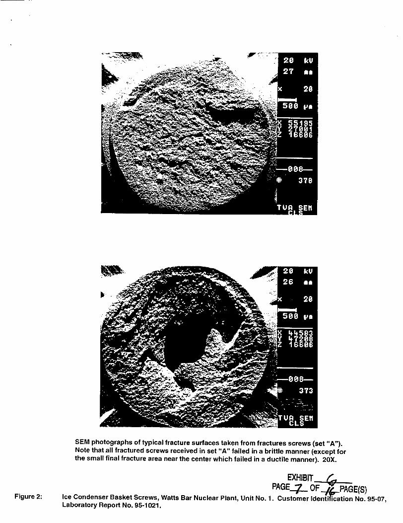
All of the fractured screws received in set "A" were examined in a Scanning Electron Microscope (SEM) in
order to determine the mode of failure. Figures 2 and 3 show that the screws fractured in a brittle manner as
indicated by the intergranular failure mode seen on all screws examined. There was usually a small final
fracture area on the fracture surface near the center of the shank that failed in a ductile manner.
An arbitrarily selected fractured screw from set "A" was cut so that a longitudinal cross-section through the
fracture surface could be examined (as seen in Figure 4). Note that a secondary crack was noticed above
the fracture surface. Closer examination of this crack revealed that it traveled in an intergranular manner.
A screw that was removed from service (set "G") was similarly !ectioned as seen in Figure 5. Note that two
cracks were found in adjacent tooth roots. Similar cracks were discovered in the new screw received in set
"A" and in the transverse section of a new screw sample examined from set "B" (see Figure 7). EDX
analysis EXHIBIT C. P 2 1 ]. 9 9 8 - 02 • •(continued on next page) PAGE___I

Technical Report 95-1021
of the crack revealed the presence of zinc (see Table I) indicating that the crack may have been present prior to plating (possibly formed when quenched during the manufacturer's heat treatment).
All screws examined had lapping from the thread-rolling process in the pitch, face, and root vicinities (see upper view of Figure 6). Lapping at the roots of the threads would be undesirable due to the fact that this is usually an area of high stress, and the lapping may initiate a fatigue crack. The lower view of Figure 6 shows a crack at a tooth root of one screw that was removed from service (set "G") that may have propagated by intergranular fatigue. Note that similar cracks were found both in the new and used screws (see Figure 7).
Two screws, one new and one used, were intentionally fractured with a hammer in order to determine the failure mechanism. SEM photography shows in Figures 8 and 9 that the used screw failed by intergranular fracture in the case and mixed-mode fracture (cleavage and void coalescence) in the core, while the new screw failed by quasi-cleavage in the case and void coalescence in the core. Three conclusions were drawn after this test was performed: 1) The fact that the new screw failed in a manner that was more ductile than the used screw corresponds to the lower hardness values of the new screws compared to those of the used screws. 2) Since both the new and used screw had ductile features on their fracture surfaces, hydrogen embrittlement from the plating process and Tempered Martensitic Embrittlement (TME) from the heat treatment were probably not factors in the failure of the screws in service. 3) The fact that the in-service screws were more brittle than the new screws can also be attributed to the used screws having a higher carbon content as compared to the new screws (see Table II).
The general microstructure of all screws was determined to be tempered martensite (see Figures 10 and 11). Note that the hardness of martensite is determined by carbon content, thus the used screws with higher carbon contents (except set "H") were harder than the new screws with lower carbon contents (the hardness values of screws in set "H" were not obtained due to lack of time).
In conclusion, the screws probably failed due to a combination of several factors:
(1) Low temperatures when the screws are in service (lowering the ductility of the screws), (2) Stresses higher than design limits, specifically at the thread roots (due to possible over-torquing), (3) The presence of stress concentrators present at the thread roots (lapping from rolling process), (4) A corrosive environment that breaks down the zinc plating and initiates rust around the threads, (5) Elevated carbon content, thus higher hardness values (again lowering the screw's ductility), (6) The presence of quench cracks in the screws upon receipt from the manufacturer, and (7) Thermal cycling which may have initiated micro-cracking or propagation of pre-existent cracks.
The mode of failure in the screws was intergranular separation, and the mechanism was stress overload.
All test equipment and instrumentation used in the performance of this evaluation are calibrated in accordance with applicable TVA standards and Quality Assurance (QA) Procedures and conform to applicable portions of ANSI N45.2, 10 CFR 50/Appendix B, and 10 CFR 21. Standards used are traceable to the National Institute of Standards Technology (NIST), natural physical constants, or commercially accepted practices. All personnel, procedures, and instructions used comply with the requirements of the Central Laboratories Services (CLS) QA Program.
In the event that additional information or subsequent testing regarding this sample should be required, please refer to Report No. 95-1021.
DAS: Attachments: Tables I-Ill
Figures 1-11 EXHIBIT
PAGE-9- OF ,4J-GE(S)

TABLE I
REPORT OF CHEMICAL COMPOSITION BY ENERGY DISPERSIVE X-RAY ANALYSIS (EDX)r
REPORT NO. 95-1021
Elemental Weight Percent (WM%)
Material in crack of screw
Element Base Metal Plating removed from service (set "G")
Aluminum - 0.4 3.4
Silicon 0.6 0.9 3.2
Phosphorus - 24.8 0.5
Calcium - 0.3 1.2
Manganese 1.0 0.6 0.7
Iron Bal. Bal. Bal.
Zinc 28.5 2.8
Copper -_0.4
Potassium 0.6
Chlorine 0.3
*EDX analysis is a semi-quantitative technique which uses no standards. TVA No. 453855
Analyzed By: Daryl Smith Date: 5131195
EXHIBIT___ PAGEJ,.3. OF 4(pPAGE(S)

TABLE II
REPORT OF CHEMICAL COMPOSITION ANALYSIS (WEIGHT PERCENT)
BY INDUCTION FURNACE COMBUSTION TECHNIQUES
REPORT NO. 95-1021
STANDARDS: 904694 (NBS 19h)
Analyzed by: Phillip Gass Date of analysis: 5122195
EXH BIT PAGE. OF PAGE(S)
Sample Carbon Sulfur
Fractured Screws (Set "A") 0.24 0.023
New Screws (Set "B") 0.22 0.021
In-service Screws (Set "C") 0.26 0.029
In-service Screws (Set "D") 0.27 0.31
In-service Screws (Set "E") 0.27 0.027
In-service Screws (Set "F") 0.27 0.023
In-service Screws (Set "G") 0.25 0.027
In-service Screws (Set "H") 0.21 0.028

TABLE IIl
REPORT OF MATERIAL HARDNESS
REPORT NO. 95-1021
STANDARD(s): 901387 (62GM)
Sample No.
Fractured Screw, Shank Case
Fractured Screw, Shank Core
Fractured Screw, Head Case
Fractured Screw, Head Core
New Screw (set "A"), Transverse Section, Case
New Screw (set "A"), Transverse Section, Core
New Screw (set "A"), Longitudinal Section, Head Core
New Screw (set "A"), Longitudinal Section, Shank Core
In-service Screw (from set "G"), Shank Case
In-service Screw (from set "G"), Shank Core
Averacqe Hardness*
54.6 HRC (625.6 HK)
"44.6 HRC (460.6 HK)
61.6 HRC (768.2 HK)
44.9 HRC (465.7 HK)
52.1 HRC (579.3 HK)
43.6 HRC (447.7 HK)
44.1 HRC (454.8 HK)
"44.2 HRC (455.3 HK)
59.5 HRC (723 HK)
42.5 HRC (432.3 HK)
LABORATORY STANDARD TEST BLOCK SET TVA No. 901387
Standard Value
556 ± 15 HK
Measured Results and Average
557.1 553.2 555.1 X 555.1 HK
Measured By: Daryl Smith Date: 5126195
* The value reported is an average of three readings. Measured values are shown in parenthesis
following converted values. Source of conversion is the Wilson Digital Microhardness Tester,
which is based on ASTM A370.
EXHIBIT PAGE..U OF __,PAGE(S)
Serial No.
62GM

I I
imam aI IIP
Left: As-received photograph of the fractured screws (set "A"). Note that the unfractured screw from this set is not shown. Right: As-received photograph of the new screws (set "B").
As-received photograph of a typical pair of used screws. Note that each set of used screws (set "C" through set "H") varied in degree of corrosion.
EXHIBIT_ PAGE.(p OFL PAGEIS 0
Ice Condenser Basket Screws, Watts Bar Nuclear Plant, Unit No. 1. Customer Identification NN.95-07, Laboratory Report No. 95-1021.
Figure 1:
1,l-I -ll'l 11" ii11-- I I111 11I11 .I I-11 i I I I I 11.
+-.•~~ 0• k••++
.2 as. 28
50 p
SEM photographs of typical fracture surfaces taken from fractures screws (set "A"). Note that all fractured screws received in set "A" failed in a brittle manner (except for the small final fracture area near the center which failed in a ductile manner). 20X.
EXHIBIT PAGE_-..4 OF PAGE(S)
Figure 2: Ice Condenser Basket Screws, Watts Bar Nuclear Plant, Unit No. 1. Customer Identification No. 95-07, Laboratory Report No. 95-1021.

SEM photographs of typical fracture topography seen on failed screws in set "A." The "rock-candy" appearance indicates that these screws failed in a brittle, intergranular manner. Top: 200X; Bottom: 1000X.
EXHIBIT____
PAGE-._ OF /4-...PAGE(S)
Figure 3: Ice Condenser Basket Screws, Watts Bar Nuclear Plant, Unit No. 1. Customer Identification No. 95-07, Laboratory Report No. 95-1021.

Longitudinal cross section through a fractured screw. The arrow points to a secondary crack above the fracture surface. 20X. As-polished.
yt M.
S, j• ,,P. .2j. A c
41-Z 'k
*..• .. " - ,;,,.. !J• .t,
•'•• -•- I,• ,. ~
Close-up views of secondary crack seen in the upper view of this Figure. Left: As-polished, 125X; Right: Vilella's etch, 400X.
EX(HIBIT-__ PAGE.. OFA PAf. -n
Ice Condenser Basket Screws, Watts Bar Nuclear Plant, Unit No. 1. Customner tdntification No. 95-7 Laboratory Report No. 95-1021.Figure 4:

..-.-0'. ."
• :. - -" , -. .... , . ' " " •. " :- •-•• •• •.- ':.".r~ t .•- ."••"
Longitudinal view of cracks present in one of the screws that were removed from service in set "G". Top: 12X; Bottom: IOOX.
EXHIBIT
PAGEJQ OF 44J'AGE(S)
Figure 5: Ice Condenser Basket Screws, Watts Bar Nuclear Plant, Unit No. 1. Customer Identification No. 95-07, Laboratory Report No. 95-1021.

As-polished, longitudinal view of lapping present at tooth root of a screw that was removed from service in set "G". 200X.
As-polished, longitudinal view of crack present at tooth root of a screw that was removed from service in set "G". 200X.
EXHIBIrT ( PAGE:4// OF4__AGE(S)
Ice Condenser Basket Screws, Watts Bar Nuclear Plant, Unit No. 1. Customer Identification No. 95-07, Laboratory Report No. 95-1021.
Figure 6:

As-polished, longitudinal view of crack present in shank, near head of a screw that was fractured in set "A" (see Figure 4). 400X.
-�4<
*..{4 A�fllJJy
As-polished, transverse view of crack present in a new screw that was received in set "B". 400X.
EXHIBITr.__6
PAGE_ 4 4 OF _ PAGE(S)
Ice Condenser Basket Screws, Watts Bar Nuclear Plant, Unit No. 1. Customer Identification No. 95-07, Laboratory Report No. 95-1021.
Figure 7:

SEM photograph of fresh fracture surface showing quasi-cleavage in the case of a new screw. 1O00OX.
SEM photograph of fresh fracture surface showing intergranular separation (with some void coalescence) in the case of a screw that was removed from service in set "D". 2000X.
EXHIBIT r PAGE411 OFJ-(4JPAGE(S)
Figure 8: Ice Condenser Basket Screws, Watts Bar Nuclear Plant, Unit No. 1. Customer Identification No. 95-07, Laboratory Report No. 95-1021.

SEM photograph of fresh fracture surface showing void coalescence in the core of a new screw. 50OX.
SEM photograph of fresh fracture surface showing mixed-mode separation (cleavage and void coalescence) in the core of a screw that was removed from service in set "D". 50OX.
EXHIBIT _ PAGE_,LI OF L4_PAGE(S)
Figure 9: Ice Condenser Basket Screws, Watts Bar Nuclear Plant, Unit No. 1. Customer Identification No. 95-07, Laboratory Report No. 95-1021.

General microstructure of a typical new screw: tempered martensite. Top: lOOX; Bottom: 500X.
EXHIBIT
PAGE_/5 OF_•PAGE($)
Figure 10: Ice Condenser Basket Screws, Watts Bar Nuclear Plant, Unit No. 1. Customer Identification No. 95-07, Laboratory Report No. 95-1021.
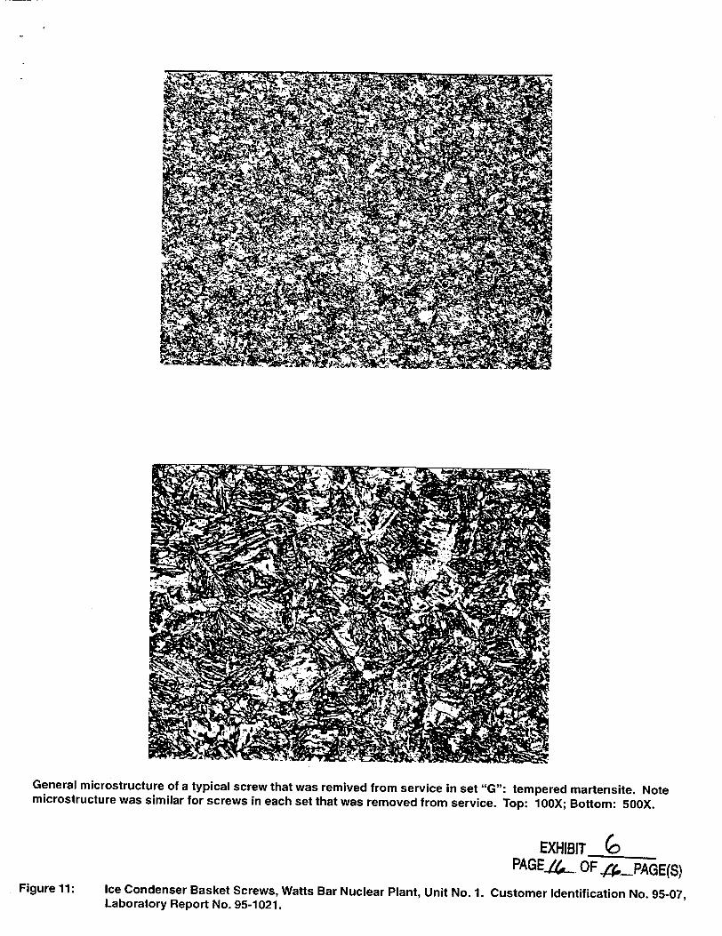
General microstructure of a typical screw that was remived from service in set "G": tempered martensite. Note microstructure was similar for screws in each set that was removed from service. Top: 10OX; Bottom: 50OX.
EXHIBIT___
PAGE.�.4 OF4P-PAGE(S)
Figure 11: Ice Condenser Basket Screws, Watts Bar Nuclear Plant, Unit No. 1. Customer Identification No. 95-07, Laboratory Report No. 95-1021.