exhibit 9 final
TRANSCRIPT

EXHIBIT 9 Cassadaga Wind LLC Cassadaga Wind Project
Cassadaga Wind Project
Case No. 14-F-0490
1001.9 Exhibit 9
Alternatives
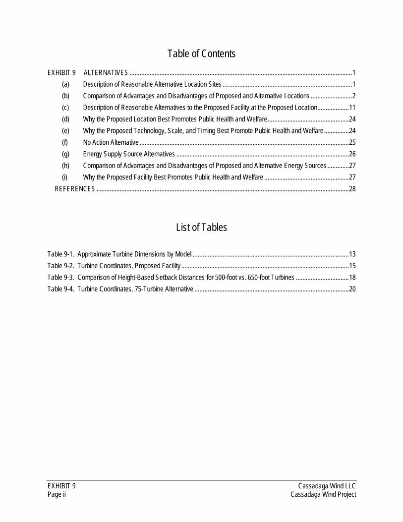
EXHIBIT 9 Cassadaga Wind LLC Page ii Cassadaga Wind Project
Table of Contents EXHIBIT 9 ALTERNATIVES ...................................................................................................................................... 1
(a) Description of Reasonable Alternative Location Sites .............................................................................. 1
(b) Comparison of Advantages and Disadvantages of Proposed and Alternative Locations ......................... 2
(c) Description of Reasonable Alternatives to the Proposed Facility at the Proposed Location ................... 11
(d) Why the Proposed Location Best Promotes Public Health and Welfare ................................................. 24
(e) Why the Proposed Technology, Scale, and Timing Best Promote Public Health and Welfare ............... 24
(f) No Action Alternative .............................................................................................................................. 25
(g) Energy Supply Source Alternatives ........................................................................................................ 26
(h) Comparison of Advantages and Disadvantages of Proposed and Alternative Energy Sources ............. 27
(i) Why the Proposed Facility Best Promotes Public Health and Welfare ................................................... 27
REFERENCES ........................................................................................................................................................ 28
List of Tables Table 9-1. Approximate Turbine Dimensions by Model .............................................................................................. 13
Table 9-2. Turbine Coordinates, Proposed Facility ..................................................................................................... 15
Table 9-3. Comparison of Height-Based Setback Distances for 500-foot vs. 650-foot Turbines ................................ 18
Table 9-4. Turbine Coordinates, 75-Turbine Alternative ............................................................................................. 20
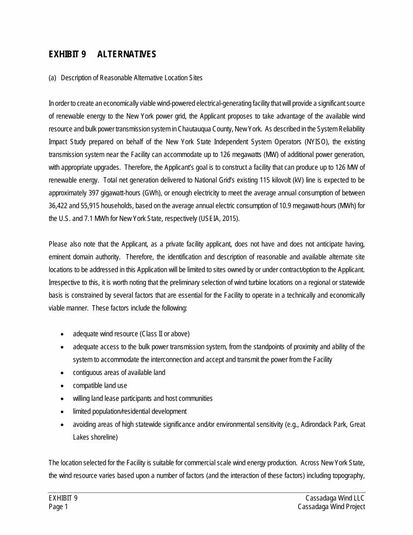
EXHIBIT 9 Cassadaga Wind LLC Page 1 Cassadaga Wind Project
EXHIBIT 9 ALTERNATIVES
(a) Description of Reasonable Alternative Location Sites
In order to create an economically viable wind-powered electrical-generating facility that will provide a significant source
of renewable energy to the New York power grid, the Applicant proposes to take advantage of the available wind
resource and bulk power transmission system in Chautauqua County, New York. As described in the System Reliability
Impact Study prepared on behalf of the New York State Independent System Operators (NYISO), the existing
transmission system near the Facility can accommodate up to 126 megawatts (MW) of additional power generation,
with appropriate upgrades. Therefore, the Applicant’s goal is to construct a facility that can produce up to 126 MW of
renewable energy. Total net generation delivered to National Grid’s existing 115 kilovolt (kV) line is expected to be
approximately 397 gigawatt-hours (GWh), or enough electricity to meet the average annual consumption of between
36,422 and 55,915 households, based on the average annual electric consumption of 10.9 megawatt-hours (MWh) for
the U.S. and 7.1 MWh for New York State, respectively (USEIA, 2015).
Please also note that the Applicant, as a private facility applicant, does not have and does not anticipate having,
eminent domain authority. Therefore, the identification and description of reasonable and available alternate site
locations to be addressed in this Application will be limited to sites owned by or under contract/option to the Applicant.
Irrespective to this, it is worth noting that the preliminary selection of wind turbine locations on a regional or statewide
basis is constrained by several factors that are essential for the Facility to operate in a technically and economically
viable manner. These factors include the following:
adequate wind resource (Class II or above)
adequate access to the bulk power transmission system, from the standpoints of proximity and ability of the
system to accommodate the interconnection and accept and transmit the power from the Facility
contiguous areas of available land
compatible land use
willing land lease participants and host communities
limited population/residential development
avoiding areas of high statewide significance and/or environmental sensitivity (e.g., Adirondack Park, Great
Lakes shoreline)
The location selected for the Facility is suitable for commercial scale wind energy production. Across New York State,
the wind resource varies based upon a number of factors (and the interaction of these factors) including topography,

EXHIBIT 9 Cassadaga Wind LLC Page 2 Cassadaga Wind Project
prevailing wind direction, and location. Commercial scale wind power projects can only be sited in certain locations
within the state that are conducive to wind energy production. The higher the wind speed at a particular site, the more
desirable that site is, since the energy produced by a given turbine is a function of the cube of the wind speed. Although
New York has a modest wind resource, this renewable resource is not evenly distributed throughout the state. Rather,
the wind resource is limited to certain unique areas in the state, which generally include coastal areas, ridgelines,
elevated plateaus, and mountain peaks. Further, the Facility Site’s proximity to an existing transmission line also
makes this location unique and desirable.
The Applicant selected the proposed site for the Facility because of the presence of the wind resource, the presence
of available land and willing landowners, the relative ease of access to the site, and the proximity and relative ease of
connecting to the existing electric transmission grid. These factors combined to make the proposed site desirable from
the standpoint of commercial-scale wind power development.
(b) Comparison of Advantages and Disadvantages of Proposed and Alternative Locations
Given the unique nature and constraints associated with the siting of wind-powered electric generation facilities (i.e.
adequate wind resource, willing land lease participants and host communities, and adequate access to the bulk power
transmission system), the Applicant is not providing an evaluation of comparative advantages and disadvantages of
alternate locations. It is simply not practicable to procure land contracts, perform environmental and engineering
studies, enter into and progress through multiple interconnection permit processes, and conduct community outreach
for alternative locations. However, this section provides information regarding the general criteria used to evaluate the
suitability of the site for the Facility.
(1) Environmental Setting
The Facility Site consists of all parcels that are hosting Facility components. The Facility Site is located within the
Allegheny Plateau physiographic province of New York State. Elevations in the area range from between 1,200
feet above mean sea level (AMSL) in eastern Chautauqua County to 1,900 feet AMSL in the western portion of
the county. The topography is strongly influenced by the underlying bedrock, which is nearly level bedded (Puglia,
1994). Bedrock in this region is typified by stratified beds of shale, sandstone, limestone, and dolostone that gently
tilt towards the southwest. See Exhibit 21 of this Application for more detailed information on geology and soils of
the Facility Site.
EXHIBIT 9 Cassadaga Wind LLC Page 3 Cassadaga Wind Project
(2) Recreational, Cultural, and Other Concurrent Uses of the Site
The Applicant has identified several recreational facilities in the area including, but not limited to, state and local
parks, trails (e.g., hiking, biking, water, snowmobile, equestrian), forests, wildlife management areas, fishing
access points, and resorts. See Exhibit 24 of this Application for more detailed information on recreational facilities
in the vicinity of the Facility Site.
A Phase 1A Historic Architectural Resources Survey & Work Plan and a Phase 1A Archeological Survey Report
& Work Plan were prepared during development of the Preliminary Scoping Statement (PSS) that included
information and recommendations intended to assist the Department of Public Service (DPS) and the New York
State Office of Parks, Recreation and Historic Preservation (NYSOPRHP) in their review of the proposed Facility.
In letters dated August 10, 2015 and September 17, 2015, respectively, NYSOPRHP indicated concurrence with
the proposed scopes of work for the Historic Architectural Resources Survey and Phase 1B Archaeological Survey.
These site-specific field studies have been completed, and additional detail on these studies is provided in Exhibit
20. No direct physical impacts to historic-architectural resources will occur as a result of the Facility. The Facility’s
potential effect on historic resources would be a change (resulting from the introduction of wind turbines) in the
visual setting associated with a given historic resource. Archaeological sites identified within the Facility Site will
be avoided during construction. See Exhibit 20 of this Application for more detailed information on cultural
resources at the Facility Site.
The proposed Facility is located in a rural portion of Chautauqua County, which is characterized by a mix of
agricultural and forested land. Land use at the Facility Site is currently dominated by dispersed residential
development and vacant land. While both temporary and permanent impacts to land use will occur, these changes
will affect a tiny percentage of leased lands, and the Facility will be compatible with the existing land uses that
dominate the Facility Site and surrounding area. Only very minor changes in land use are anticipated within the
Facility Site as a result of Facility operation, and no changes are predicted outside the Facility Site. Aside from
occasional maintenance and repair activities, Facility operation will not interfere with on-going land use (i.e.,
farming or forestry activities). See Exhibit 4 of this Application for more detailed information on land use at the
Facility Site.
(3) Engineering Feasibility
A Preliminary Geotechnical Assessment was conducted that included literature review of publicly available
information and data pertaining to surface and subsurface soil, bedrock, and groundwater conditions in the vicinity

EXHIBIT 9 Cassadaga Wind LLC Page 4 Cassadaga Wind Project
of the proposed Facility, as well as preliminary geotechnical investigations at select locations within the Facility
Site to obtain additional information pertaining to subsurface soil and bedrock features to assess the general
constructability of the proposed Facility. The Assessment concluded that the Facility Site is generally suitable for
the proposed Facility (GZA, 2015). The literature review and preliminary borings suggest that foundations for the
proposed turbines can be constructed on shallow mat foundations, and will not require deep foundation elements
(e.g., caissons, piles, etc.). Due to the apparent depth of bedrock and its low rock quality, it does not appear that
blasting will be required for construction of the turbine foundations. It is expected that the excavations for the
construction of the proposed Facility will be completed using conventional construction equipment including
bulldozers, track hoes, and possibly pan excavators. For additional information about the Geotechnical
Assessment and the engineering feasibility of the site, please see Exhibit 21 of this Application.
The Applicant has conducted a rigorous wind resource analysis for this Facility, the intent of which is to optimize
the turbine layout to maximize energy production within the context of the existing, site-specific constraints. The
detailed results of these analyses are proprietary and are typically retained as trade secrets. Therefore, a copy of the
wind meteorological analysis is not attached to this Application, but rather will be provided to DPS under separate
cover. The Applicant is seeking the requisite trade secret protection for this information pursuant to NY Public
Officer’s Law Section 87(2)(d) and 16 NYCRR 6-1.4. See Exhibit 6 of this Application for additional information
about the wind resource at the Facility Site.
With respect to interconnections, please see (b)(4) below.
(4) Reliability and Electric System Effects
A System Reliability Impact Study (SRIS) was conducted in January 2015 to evaluate the impact of the Facility on
the reliability of the New York State Transmission System and to evaluate alternatives to eliminate adverse
reliability impacts, if any, resulting from the Facility. The SRIS, which is discussed in more detail in Exhibit 5,
evaluated a number of power flow base cases, as determined by the NYISO, including 2018 summer peak, winter
peak, and light load. The SRIS also included stability analyses for the system summer peak and light load
conditions, both with and without the Facility. The Facility is not expected to result in adverse impacts to the
transmission system. See Exhibit 5 for more detailed information on reliability and electric system effects.

EXHIBIT 9 Cassadaga Wind LLC Page 5 Cassadaga Wind Project
(5) Environmental Impacts
Despite the positive effects anticipated as a result of the Facility, its construction and operation will necessarily
result in certain unavoidable impacts to the environment. The majority of these environmental impacts will result
from construction activities and will be temporary in nature. Long-term unavoidable impacts associated with
operation and maintenance of the Facility are anticipated to be relatively limited, but will include turbine visibility,
wildlife habitat changes, and minor impacts to streams and wetlands.
The presence (i.e., visibility) of the turbines will likely result in a change in perceived land use from some
viewpoints. Evaluation by registered landscape architects indicates that the Facility’s overall contrast with the
visual/aesthetic character of the area will generally be minimal to moderate. However, based on the contrast rating
scores and comments, greater levels of contrast can be anticipated where foreground or near-midground views of
turbines (i.e., under 1.5 mile) are available from residences or areas of relatively higher overall scenic quality.
Conversely, contrast is reduced when turbines are partially screened, viewed at greater distances, seen in the
context of a working agricultural landscape, or viewed in a setting with existing visual clutter. Based on experience
with currently operating wind power projects elsewhere, public reaction to the Facility is likely to be generally
positive, but highly variable based on proximity to the turbines, the affected landscape, and personal attitude of
the viewer regarding wind power. See Exhibit 24 of this Application for more detailed information on turbine
visibility and visual impacts in the vicinity of the Facility Site.
The Facility layout was designed, in part, through an iterative process of identifying wetland locations and siting
Facility components to avoid and minimize impacts to surface waters and wetlands wherever possible. Despite
avoiding and minimizing wetland impacts where practicable, some wetland impacts are unavoidable. Where
avoidance was not practicable, narrow and/or previously disturbed portions of the wetlands were chosen for
crossing locations. The Applicant will implement compensatory mitigation that will be determined in consultation
with the New York State Department of Environmental Conservation (NYSDEC) and United States Army Corps of
Engineers (USACE). This mitigation will ensure “no net loss” of wetlands, and may include the purchase of credits
from an approved in-lieu-fee program, creation of an on-site compensatory mitigation area, restoration or
enhancement of wetlands in the impacted watershed, or some combination of these options. See Exhibit 22 of
this Application for more detailed information on impacts to wetlands at the Facility Site.
Facility components have been sited so as to minimize impact to undisturbed wildlife habitat. Many of the proposed
turbines are sited in or adjacent to agricultural land, which generally provides habitat for only a limited number of
wildlife species. In addition, these areas are already subject to regular periodic disturbance in the form of mowing,
EXHIBIT 9 Cassadaga Wind LLC Page 6 Cassadaga Wind Project
plowing, harvesting, etc. Approximately 509.5 acres of wildlife habitat will be temporarily disturbed during
construction, while permanent loss through conversion of natural habitat to built facilities will total 81.2 acres. On
a landscape scale, there is abundant availability of habitats within the nearby landscape similar to those at the
Facility Site. See Exhibit 22 of this Application for more detailed information on impacts to wildlife habitat within
the Facility Site.
The proposed Facility will not contribute to global temperature increases. On the contrary, the Facility is anticipated
to have long-term beneficial effects on the use and conservation of energy resources. The operating Facility will
generate up to 126 MW of electricity without consuming cooling water, and without emitting pollutants or heat-
trapping greenhouse gases. Electricity generated from zero-emission wind energy facilities can displace the
electricity generated from conventional power plants, thereby reducing the emissions of conventional air pollutants,
such as mercury; sulfur and nitrogen oxides (acid rain precursors); and carbon dioxide (linked to global climate
change). This conclusion is supported by a 2008 U.S. Department of Energy, National Renewable Energy
Laboratory report that states, “Wind energy is a preferred power source on an economic basis, because the
operating costs to run the turbines are very low and there are no fuel costs. Thus, when the wind turbines produce
power, this power source will displace generation at fossil fueled plants, which have higher operating and fuel
costs.” On a long-term basis, wind generated power also reduces the need to construct and operate new fossil
fueled power plants (Jacobsen & High, 2008). Please also see section (f) below for additional information on the
benefits of wind power.
According to an extrapolation of 2012 data released in 2015 by the U.S. Environmental Protection Agency
Emissions and Generation Resource Integrated Database (eGRID2012), the Facility is expected to displace
approximately 244,086.4 tons of carbon dioxide (CO2) emissions from conventional power plants on an annual
basis (USEPA, 2015a), which represents approximately 0.7% of CO2 produced by the electricity generation sector
in New York State (USEPA, 2105b). See Exhibit 8 for additional information, including an explanation of how
these displacements were calculated.
(6) Economic Considerations
The purpose of the Facility is to create an economically viable wind-powered electrical-generating facility that will
provide a significant source of renewable energy to the New York power grid. To fulfil these goals, adequate wind
resource and access to the existing transmission system are some of the most important economic considerations
is selecting a Facility Site. The Facility Site has ample wind resource for the proposed Facility, and is located in
close proximity to the existing bulk power transmission system. See Exhibit 6 of this Application for additional
EXHIBIT 9 Cassadaga Wind LLC Page 7 Cassadaga Wind Project
information about the wind resource at the Facility Site, and Exhibit 34 for information about the electric
interconnection.
This Application provides an estimate of the total capital costs of the Facility in Exhibit 14. However, because
capital cost information is considered proprietary and is typically retained as a trade secret, this data has been
provided in the form of an internal work paper that also describes the assumptions in estimating the total capital
costs. The Applicant is seeking the requisite trade secret protection for this information pursuant to NY Public
Officer’s Law Section 87(2)(d) and 16 NYCRR 6-1.4.
The proposed Facility will have a positive impact on the local economy. Construction will employ a total work force
of approximately 75 on-site employees. Of these, 70 of the jobs will occur in Construction Labor, while five of the
jobs includes the disciplines of engineers and other professional services. Operations and maintenance of the
proposed Facility will generate seven full full-time jobs with combined estimated annual earnings of approximately
$600,000. In addition to the jobs created and the wages paid to the work force, the Facility will have a direct
economic benefit from the first round of buying/selling, which includes the purchase of goods from local sources
(such as fuel), the spending of income earned by workers, annual labor revenues, and the income effect of taxes.
These direct effects will result in additional induced economic benefits in other sectors.
The Project operation will result in payment to local landowners in association with the lease agreements executed
to host Project components, which will be in addition to any income generated from the existing land use (e.g.
agricultural production). Based on the specifics of the lease and easement agreements, the Applicant estimates
that these payments will total approximately $1.2 million during the first year (construction), and approximately
$950,000 on an annual basis each year the Facility is in operation. These lease payments will have a positive
impact on the region, to the extent that landowners will spend their revenue locally.
The proposed Facility will have a significant positive impact on the local tax base, including local school districts
and other taxing districts that service the area where the proposed wind farm is to be located. Taxing districts
within the Project Area include Chautauqua County, the Town of Cherry Creek, the Town of Charlotte, the Town
of Arkwright, the Town of Stockton, Cassadaga Valley Central School District, and Pine Valley Central School
District. It is important to note that the proposed Facility will make few, if any, demands on local government
services. Therefore, payments made to local taxing jurisdictions will be net positive gains and represent an
important economic benefit to the local area. See Exhibit 27 of this Application for more detailed information on
the socioeconomic effects of the proposed Facility.
EXHIBIT 9 Cassadaga Wind LLC Page 8 Cassadaga Wind Project
(7) Environmental Justice
No environmental justice areas occur within the Facility Site, and the Facility is not expected to impact any
environmental justice areas. See Exhibit 28 for additional information about the closest environmental justice
areas to the Facility Site.
(8) Security, Public Safety, and Emergency Planning
Overall safety and security risks associated with the Facility are anticipated to be minimal. To ensure the safety
of construction and operations personnel, as well as the security of the Facility as a whole, the Applicant has
developed, and will implement plans for site security, worker safety, and emergency action, which are described
in Exhibit 18 of this Application.
The Applicant has developed a Preliminary Emergency Action Plan (EAP), which is summarized in detail in Exhibit
18. The information contained in the EAP has been developed in conjunction with local emergency service
providers, and outlines the procedures to follow in the event of an emergency. The EAP will be made available to
the employees of the Applicant and any visiting guests or workers at the Facility. A discussion of the various
elements contained within the EAP is provided in Exhibit 18 of this Application.
(9) Public Health
The Facility is not expected to result in any public health concerns. Claims of health impacts related to sound and
shadow flicker have been considered, but all significant, scientifically reviewed studies on the subject have found
those claims to be largely unfounded. The design of the Facility adequately considered any reasonable standards
and is not expected to result in any public health concerns. See Exhibit 19. See Exhibit 15 of this Application for
additional information about public health.
(10) Vulnerability to Seismic Disturbances and Climate Change Impacts
Based on the 2014 New York State Seismic Hazard Map (USGS, 2014), the Facility Site is located in an area of
relatively low seismic hazard, with a 2% or less chance that peak ground acceleration in a 50 year window is
between 4% and 8% of standard gravity. An earthquake occurred in Attica, New York (about 75 miles northeast
of the Facility Site) in 1966 with a Richter scale magnitude of 4.7 (USGS, 2015). There are several faults mapped
in Chautauqua County (Jacobi, 2002). The Mayville fault, Charlotte Center fault, and an unnamed fault are located
EXHIBIT 9 Cassadaga Wind LLC Page 9 Cassadaga Wind Project
within the vicinity of the Facility Site. However, these faults are not associated with any historic earthquakes
(USGS, 2015). Furthermore, the USGS Earthquake Hazards Program does not list any young faults, or faults that
have had displacement in the Holocene epoch within the vicinity of the Facility Site. See Exhibit 21 of this
Application for a more detailed discussion of the Facility’s potential vulnerability to seismology.
With respect to climate change, New York State is increasingly faced with a changing climate that is beyond the
range of past experiences. Statewide annual temperatures have increased by approximately 0.6ºF per decade
since 1970. This increase is most pronounced during the winter, when warming has exceeded 1.1ºF per decade.
Overall, there has been no discernable trend in annual precipitation since the start of the 20th century, although
intense precipitation events have increased in recent decades (NYSERDA, 2011). Increasing greenhouse gas
concentrations are projected to lead to continual steady temperature increases, as well as significant increases in
the frequency, intensity, and duration of extreme heat events and coastal flooding. Intense precipitation events
are also projected to become increasingly frequent, while cold air outbreaks are projected to gradually become
less frequent (NYSERDA, 2014).
The Facility Site is located along upland ridges in western New York, far from coastal areas. As a result, the site
is not expected to be vulnerable to rising sea levels. More frequent intense precipitation events could lead to more
frequent flooding in low-lying areas. Review of Federal Emergency Management Agency (FEMA) flood insurance
rate maps indicate that 100-year floodplains are mapped in several stream valleys within the Facility Site, including
along portions of Mill Creek and unnamed tributaries of Cassadaga Creek. However, the wind turbines are located
in upland areas, well away from these floodplains. The crossing of Mill Creek by a co-located section of
transmission line and collection line are the only Facility components proposed to be located within a floodplain.
The transmission line poles will be located outside the floodplain to the extent practicable.
Temperature increases will drive many changes in species composition and ecosystem structure across the state
(NYSERDA, 2011). For example, forest composition is expected to slowly change, with oak-hickory forests
becoming dominant in many areas currently occupied by maple-beech forests (Iverson et al., 2008). However,
the ecological communities most vulnerable to climate change (e.g., boreal spruce-fir forests, high elevation alpine
tundra communities, etc.) do not occur at the Facility Site.
(11) Objectives and Capabilities of the Applicant
With respect to capabilities, the Applicant is a wholly owned subsidiary of EverPower Wind Holdings, Inc.
(“EverPower”). Headquartered in Pittsburgh, Pennsylvania with offices in New York and Ohio, EverPower is a

EXHIBIT 9 Cassadaga Wind LLC Page 10 Cassadaga Wind Project
developer of utility grade wind projects. Since its founding in 2002, EverPower has used a unique approach to
wind power development by partnering with landowners and communities to establish itself as a premier developer,
owner, and operator of wind energy facilities in the U.S. To date, EverPower currently has seven operational wind
facilities with a nameplate capacity of approximately 752 MW, including the Howard Wind Project in Steuben
County, New York. The Howard Wind Project has a total generating capacity of 55.35 MWs and uses 27 Repower
MM92 turbines. The first 25 turbines became commercial operational in 2011, and the two-turbine second phase
became operational in 2012.
The objective of the proposed Facility is to create an economically viable wind-powered electrical-generating
facility that will provide a source of renewable energy to the New York power grid to:
Satisfy regional energy needs in an efficient and environmentally sound manner;
Supplement and offset fossil-fuel electricity generation in the region, with emission-free, wind-generated
energy;
Reduce the amount of electricity imported to New York State;
Realize the full potential of the wind resource at the Facility Site;
Provide energy that is not susceptible to fluctuations in commodity prices;
Produce electricity without the generation of carbon dioxide or other greenhouse gases that contribute to
climate change;
Promote the long-term economic viability of rural areas in New York;
Provide good-paying job opportunities in rural areas; and
Assist New York State in meeting its proposed Renewable Portfolio Standard and State Energy Plan
goals for the consumption of renewable energy in the State.
(12) Wind Meteorological Analysis
Wind resource analyses were performed in order to optimize the turbine layout for maximum energy production
within the context of the existing, site-specific constraints. These analyses are described in in greater detail in
Exhibit 6 of this Application. The detailed results of these analyses are proprietary and are typically retained as
trade secrets. Therefore, a copy of the wind meteorological analysis is not being provided with this Application,
but rather will be provided to DPS under separate cover. The Applicant is seeking the requisite trade secret
protection for this information pursuant to NY Public Officer’s Law Section 87(2)(d) and 16 NYCRR 6-1.4.
EXHIBIT 9 Cassadaga Wind LLC Page 11 Cassadaga Wind Project
Publicly available wind resource maps suggest a suitable wind resource along ridgetops at the Facility Site (AWS
Truewind, 2007; NREL & AWS Truepower, 2010). The Cassadaga Wind Project will have a nameplate capacity
of up to 126 MW, and is expected to operate at an annual net capacity factor of approximately 36%. This means
that over the course of a full calendar year the Project would produce up to 397,353 megawatt hours (MWh) of
energy (i.e., 126 MW x 24 hrs/day x 365 days x 36%). This is enough electricity to meet the average annual
consumption of between approximately 36,422 and 55,915 households, based on the average annual electric
consumption of 10.9 MWh for the U.S. and 7.1 MWh for New York State, respectively (USEIA, 2015).
(c) Description of Reasonable Alternatives to the Proposed Facility at the Proposed Location
Unlike state or municipal entities, private developers do not have the power of condemnation or eminent domain.
Consequently, the Applicant does not have the unfettered ability to locate facilities in any area or on any parcel of land.
Facilities can only be sited on private property where the landowner has agreed to allow such construction, and is
further constrained by the factors described in (c)(4) below.
(1) General Arrangement and Design
The general arrangement and design of the Facility is influenced by a number of factors, as discussed in detail in
(c)(4) below.
(2) Technology
Private landowner agreements strictly limit the use of land to a wind power project, and as such, do not allow for
the siting of other alternative energy production facilities (e.g., solar, hydro, biomass, or fossil fuel). Accordingly,
other power generation technologies are not reasonable alternatives, and do not warrant consideration in this
Article 10 Application.
The turbines proposed for the Facility will utilize the latest in wind power generation technology to enhance project
efficiency and safety. Each wind turbine consists of three major components: the tower, the nacelle, and the rotor.
The nacelle sits atop the tower, and the rotor hub is mounted to the front of the nacelle. “Hub height” is the height
of the center of the rotor, as measured from the base of the tower (excluding the subsurface foundation) to the top
of the tower, while total turbine height is the height of the entire turbine, as measured from the tower base to the
tip of the highest blade when rotated to the highest position. Descriptions of each of the turbine components are
provided below.
EXHIBIT 9 Cassadaga Wind LLC Page 12 Cassadaga Wind Project
Tower: The tubular towers used for megawatt-scale turbines are tubular conical steel structures manufactured
in multiple sections. Each tower will have an access door in the base section and internal lighting, along with
an internal ladder and/or mechanical lifts to access the nacelle. The towers will be painted white or off-white
in accordance with Federal Aviation Administration (FAA) regulations designed to make the structures more
visible to aircraft when viewed from above, as light colors contrast sharply against the dark-colored ground.
This also has the benefit of reducing visibility from ground vantage points, by making them difficult to see
against the pale background of the sky.
Nacelle: The main mechanical components of the wind turbine are housed in the nacelle. These components
include the drive train, gearbox, and generator. The nacelle is housed in a steel reinforced fiberglass shell
that protects internal machinery from the environment and dampens noise emissions. The housing is
designed to allow for adequate ventilation to cool internal machinery. The nacelle is equipped with an external
anemometer and a wind vane that signals wind speed and direction information to an electronic controller.
Attached to the top of some of the nacelles, per specifications of the FAA, will be a single, medium intensity
aviation warning light. These lights are anticipated to be flashing red strobes (L-864) that operate only at
night. The nacelle is mounted on a yaw ring bearing that allows it to rotate ("yaw") into the wind to maximize
wind capture and energy production.
Rotor: A rotor assembly is mounted to the nacelle to operate upwind of the tower. Each rotor consists of
three (3) composite blades that will be up to 68 meters (223 feet) in length, with a maximum rotor diameter of
up to 136 meters (446 feet). The rotor attaches to the drive train at the front of the nacelle. Hydraulic motors
within the rotor hub feather each blade according to wind conditions, which enables the turbine to operate
efficiently at varying wind speeds. The rotor can spin at varying speeds to operate more efficiently. Depending
on the turbine model selected, the wind turbines will begin generating energy at wind speeds as low as 3
meters per second (m/s) [6.7 miles per hour (mph)], and cut out at maximum wind speeds of 25 m/s (55.9
mph).
Due to market factors such as availability and cost, a specific turbine model has not yet been selected for the
Facility. However, turbine models that have been determined to be suitable for this site include the Gamesa G114
(2.1 MW), Gamesa G114 (2.625 MW), Gamesa G126 (2.5 MW), General Electric (GE) 2.3-117 (2.3 MW), GE
2.75-120 (2.75 MW), GE 3.2-130 (3.2 MW), Nordex N117 (3.0 MW), Siemens SWT-2.3-120 (2.3 MW), Siemens
SWT-3.3-130 (3.3 MW), Vestas V112 (3.0 MW), Vestas V117 (3.3 MW), Vestas V126 (3.3 MW), and Vestas V136
(3.45 MW). Table 9-1 presents the dimensions for each of the alternative turbine models.
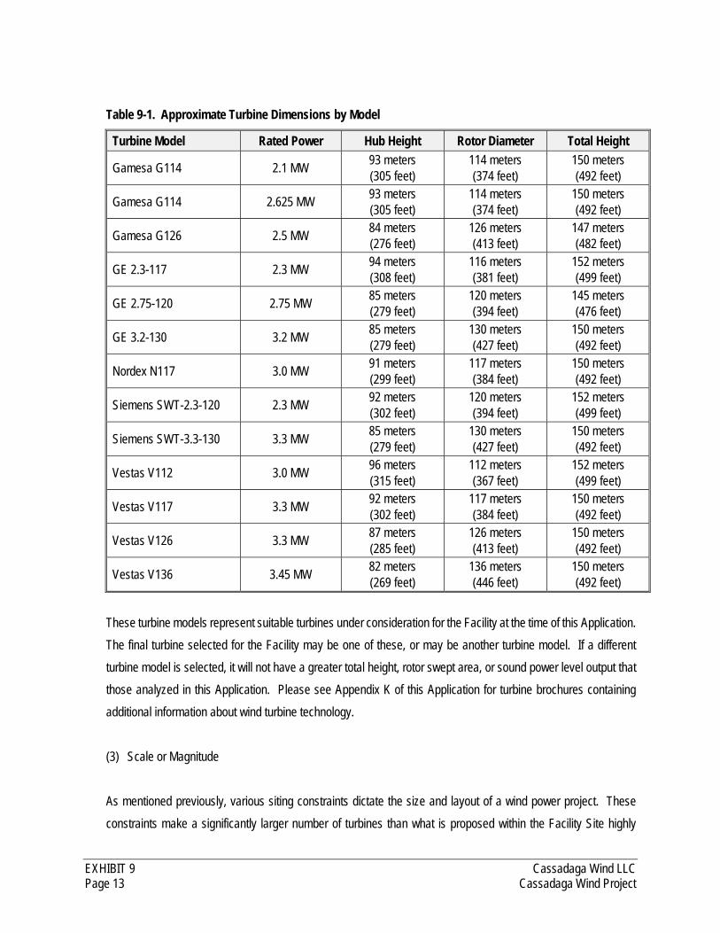
EXHIBIT 9 Cassadaga Wind LLC Page 13 Cassadaga Wind Project
Table 9-1. Approximate Turbine Dimensions by Model
Turbine Model Rated Power Hub Height Rotor Diameter Total Height
Gamesa G114 2.1 MW 93 meters (305 feet)
114 meters (374 feet)
150 meters (492 feet)
Gamesa G114 2.625 MW 93 meters (305 feet)
114 meters (374 feet)
150 meters (492 feet)
Gamesa G126 2.5 MW 84 meters (276 feet)
126 meters (413 feet)
147 meters (482 feet)
GE 2.3-117 2.3 MW 94 meters (308 feet)
116 meters (381 feet)
152 meters (499 feet)
GE 2.75-120 2.75 MW 85 meters (279 feet)
120 meters (394 feet)
145 meters (476 feet)
GE 3.2-130 3.2 MW 85 meters (279 feet)
130 meters (427 feet)
150 meters (492 feet)
Nordex N117 3.0 MW 91 meters (299 feet)
117 meters (384 feet)
150 meters (492 feet)
Siemens SWT-2.3-120 2.3 MW 92 meters (302 feet)
120 meters (394 feet)
152 meters (499 feet)
Siemens SWT-3.3-130 3.3 MW 85 meters (279 feet)
130 meters (427 feet)
150 meters (492 feet)
Vestas V112 3.0 MW 96 meters (315 feet)
112 meters (367 feet)
152 meters (499 feet)
Vestas V117 3.3 MW 92 meters (302 feet)
117 meters (384 feet)
150 meters (492 feet)
Vestas V126 3.3 MW 87 meters (285 feet)
126 meters (413 feet)
150 meters (492 feet)
Vestas V136 3.45 MW 82 meters (269 feet)
136 meters (446 feet)
150 meters (492 feet)
These turbine models represent suitable turbines under consideration for the Facility at the time of this Application.
The final turbine selected for the Facility may be one of these, or may be another turbine model. If a different
turbine model is selected, it will not have a greater total height, rotor swept area, or sound power level output that
those analyzed in this Application. Please see Appendix K of this Application for turbine brochures containing
additional information about wind turbine technology.
(3) Scale or Magnitude
As mentioned previously, various siting constraints dictate the size and layout of a wind power project. These
constraints make a significantly larger number of turbines than what is proposed within the Facility Site highly
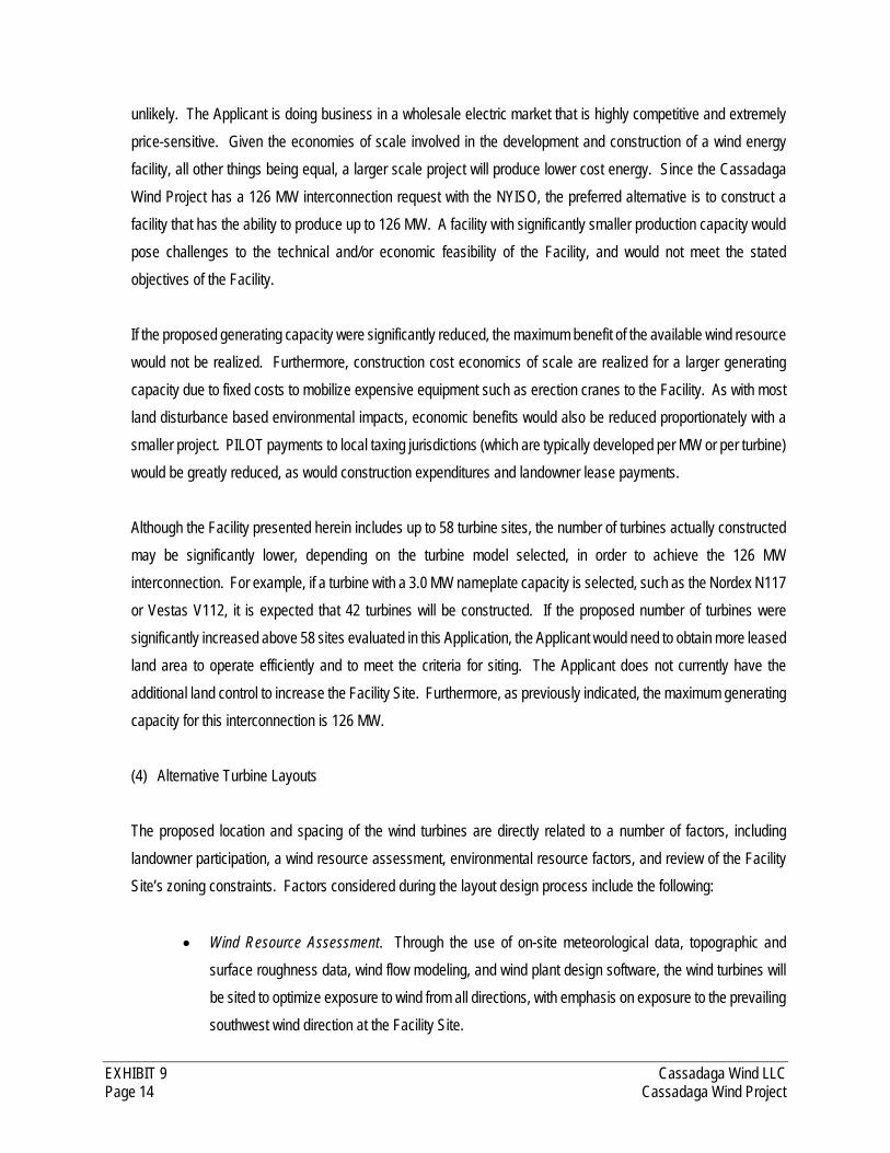
EXHIBIT 9 Cassadaga Wind LLC Page 14 Cassadaga Wind Project
unlikely. The Applicant is doing business in a wholesale electric market that is highly competitive and extremely
price-sensitive. Given the economies of scale involved in the development and construction of a wind energy
facility, all other things being equal, a larger scale project will produce lower cost energy. Since the Cassadaga
Wind Project has a 126 MW interconnection request with the NYISO, the preferred alternative is to construct a
facility that has the ability to produce up to 126 MW. A facility with significantly smaller production capacity would
pose challenges to the technical and/or economic feasibility of the Facility, and would not meet the stated
objectives of the Facility.
If the proposed generating capacity were significantly reduced, the maximum benefit of the available wind resource
would not be realized. Furthermore, construction cost economics of scale are realized for a larger generating
capacity due to fixed costs to mobilize expensive equipment such as erection cranes to the Facility. As with most
land disturbance based environmental impacts, economic benefits would also be reduced proportionately with a
smaller project. PILOT payments to local taxing jurisdictions (which are typically developed per MW or per turbine)
would be greatly reduced, as would construction expenditures and landowner lease payments.
Although the Facility presented herein includes up to 58 turbine sites, the number of turbines actually constructed
may be significantly lower, depending on the turbine model selected, in order to achieve the 126 MW
interconnection. For example, if a turbine with a 3.0 MW nameplate capacity is selected, such as the Nordex N117
or Vestas V112, it is expected that 42 turbines will be constructed. If the proposed number of turbines were
significantly increased above 58 sites evaluated in this Application, the Applicant would need to obtain more leased
land area to operate efficiently and to meet the criteria for siting. The Applicant does not currently have the
additional land control to increase the Facility Site. Furthermore, as previously indicated, the maximum generating
capacity for this interconnection is 126 MW.
(4) Alternative Turbine Layouts
The proposed location and spacing of the wind turbines are directly related to a number of factors, including
landowner participation, a wind resource assessment, environmental resource factors, and review of the Facility
Site’s zoning constraints. Factors considered during the layout design process include the following:
Wind Resource Assessment. Through the use of on-site meteorological data, topographic and
surface roughness data, wind flow modeling, and wind plant design software, the wind turbines will
be sited to optimize exposure to wind from all directions, with emphasis on exposure to the prevailing
southwest wind direction at the Facility Site.
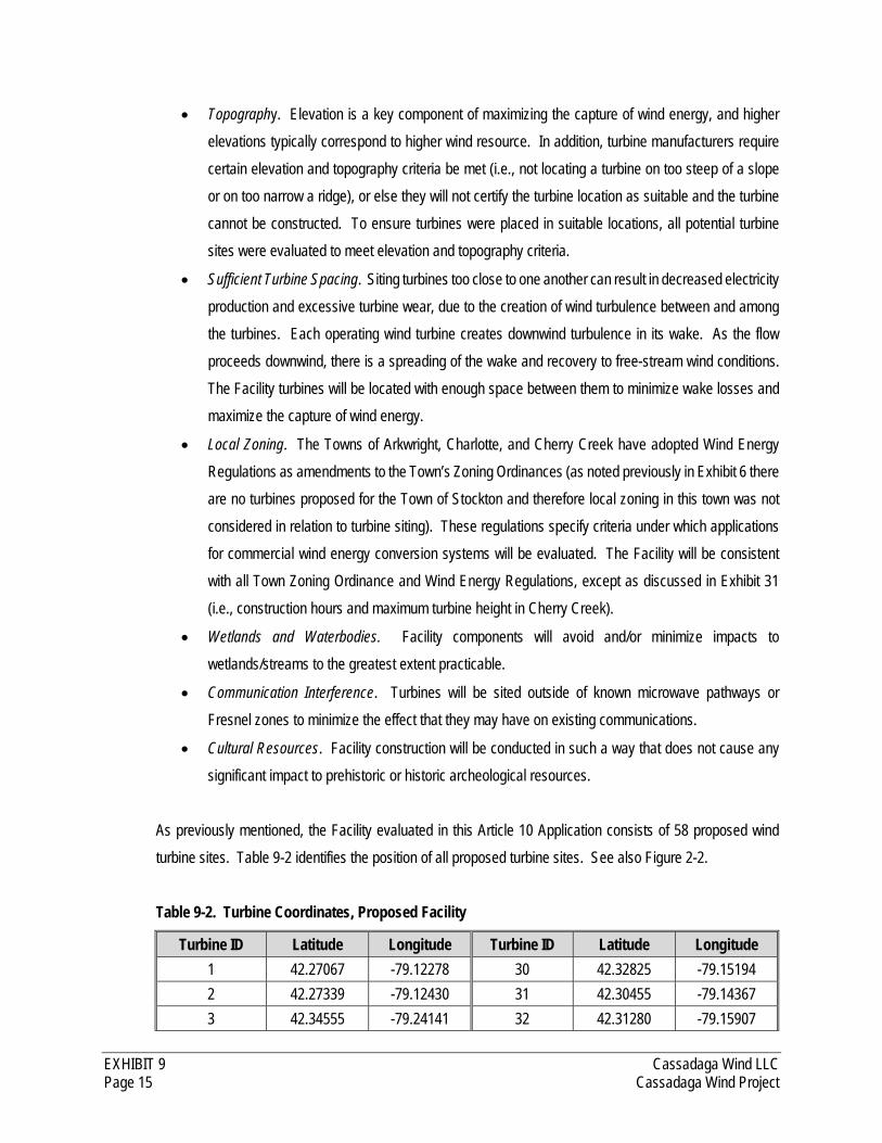
EXHIBIT 9 Cassadaga Wind LLC Page 15 Cassadaga Wind Project
Topography. Elevation is a key component of maximizing the capture of wind energy, and higher
elevations typically correspond to higher wind resource. In addition, turbine manufacturers require
certain elevation and topography criteria be met (i.e., not locating a turbine on too steep of a slope
or on too narrow a ridge), or else they will not certify the turbine location as suitable and the turbine
cannot be constructed. To ensure turbines were placed in suitable locations, all potential turbine
sites were evaluated to meet elevation and topography criteria.
Sufficient Turbine Spacing. Siting turbines too close to one another can result in decreased electricity
production and excessive turbine wear, due to the creation of wind turbulence between and among
the turbines. Each operating wind turbine creates downwind turbulence in its wake. As the flow
proceeds downwind, there is a spreading of the wake and recovery to free-stream wind conditions.
The Facility turbines will be located with enough space between them to minimize wake losses and
maximize the capture of wind energy.
Local Zoning. The Towns of Arkwright, Charlotte, and Cherry Creek have adopted Wind Energy
Regulations as amendments to the Town’s Zoning Ordinances (as noted previously in Exhibit 6 there
are no turbines proposed for the Town of Stockton and therefore local zoning in this town was not
considered in relation to turbine siting). These regulations specify criteria under which applications
for commercial wind energy conversion systems will be evaluated. The Facility will be consistent
with all Town Zoning Ordinance and Wind Energy Regulations, except as discussed in Exhibit 31
(i.e., construction hours and maximum turbine height in Cherry Creek).
Wetlands and Waterbodies. Facility components will avoid and/or minimize impacts to
wetlands/streams to the greatest extent practicable.
Communication Interference. Turbines will be sited outside of known microwave pathways or
Fresnel zones to minimize the effect that they may have on existing communications.
Cultural Resources. Facility construction will be conducted in such a way that does not cause any
significant impact to prehistoric or historic archeological resources.
As previously mentioned, the Facility evaluated in this Article 10 Application consists of 58 proposed wind
turbine sites. Table 9-2 identifies the position of all proposed turbine sites. See also Figure 2-2.
Table 9-2. Turbine Coordinates, Proposed Facility
Turbine ID Latitude Longitude Turbine ID Latitude Longitude
1 42.27067 -79.12278 30 42.32825 -79.15194
2 42.27339 -79.12430 31 42.30455 -79.14367
3 42.34555 -79.24141 32 42.31280 -79.15907
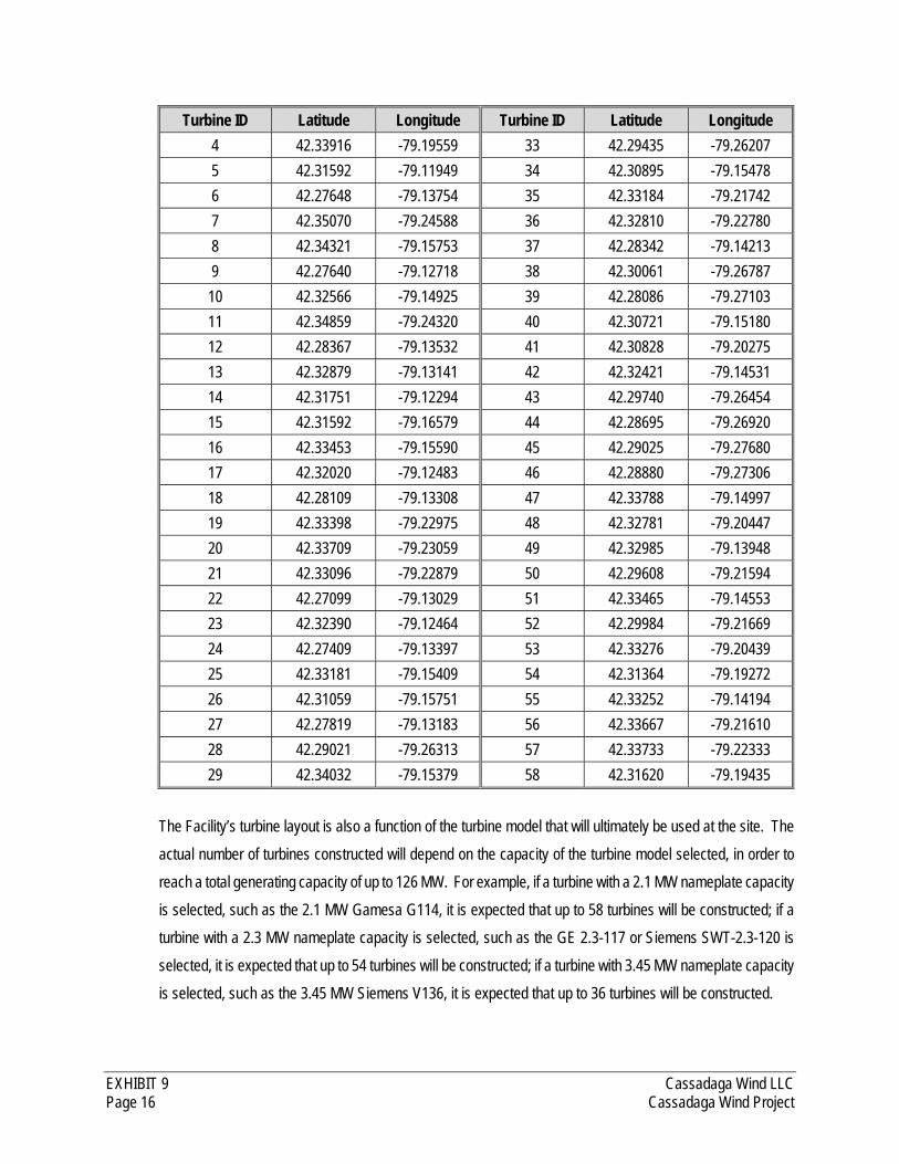
EXHIBIT 9 Cassadaga Wind LLC Page 16 Cassadaga Wind Project
Turbine ID Latitude Longitude Turbine ID Latitude Longitude
4 42.33916 -79.19559 33 42.29435 -79.26207
5 42.31592 -79.11949 34 42.30895 -79.15478
6 42.27648 -79.13754 35 42.33184 -79.21742
7 42.35070 -79.24588 36 42.32810 -79.22780
8 42.34321 -79.15753 37 42.28342 -79.14213
9 42.27640 -79.12718 38 42.30061 -79.26787
10 42.32566 -79.14925 39 42.28086 -79.27103
11 42.34859 -79.24320 40 42.30721 -79.15180
12 42.28367 -79.13532 41 42.30828 -79.20275
13 42.32879 -79.13141 42 42.32421 -79.14531
14 42.31751 -79.12294 43 42.29740 -79.26454
15 42.31592 -79.16579 44 42.28695 -79.26920
16 42.33453 -79.15590 45 42.29025 -79.27680
17 42.32020 -79.12483 46 42.28880 -79.27306
18 42.28109 -79.13308 47 42.33788 -79.14997
19 42.33398 -79.22975 48 42.32781 -79.20447
20 42.33709 -79.23059 49 42.32985 -79.13948
21 42.33096 -79.22879 50 42.29608 -79.21594
22 42.27099 -79.13029 51 42.33465 -79.14553
23 42.32390 -79.12464 52 42.29984 -79.21669
24 42.27409 -79.13397 53 42.33276 -79.20439
25 42.33181 -79.15409 54 42.31364 -79.19272
26 42.31059 -79.15751 55 42.33252 -79.14194
27 42.27819 -79.13183 56 42.33667 -79.21610
28 42.29021 -79.26313 57 42.33733 -79.22333
29 42.34032 -79.15379 58 42.31620 -79.19435
The Facility’s turbine layout is also a function of the turbine model that will ultimately be used at the site. The
actual number of turbines constructed will depend on the capacity of the turbine model selected, in order to
reach a total generating capacity of up to 126 MW. For example, if a turbine with a 2.1 MW nameplate capacity
is selected, such as the 2.1 MW Gamesa G114, it is expected that up to 58 turbines will be constructed; if a
turbine with a 2.3 MW nameplate capacity is selected, such as the GE 2.3-117 or Siemens SWT-2.3-120 is
selected, it is expected that up to 54 turbines will be constructed; if a turbine with 3.45 MW nameplate capacity
is selected, such as the 3.45 MW Siemens V136, it is expected that up to 36 turbines will be constructed.

EXHIBIT 9 Cassadaga Wind LLC Page 17 Cassadaga Wind Project
The turbine model ultimately selected for this Facility will be based on numerous factors, such as site
suitability, availability, and price. If all 58 turbine sites are not needed because a 2.3 MW or larger turbine is
selected, the turbine locations to be utilized will be chosen from among the 58 specific locations identified
above in Table 9-2. This determination will be made based on the wind resource, and other siting factors
such as distance to the collection substation, construction costs, environmental impacts that could be avoided
or minimized, etc. However, even though fewer than 58 turbines may be built, this Application assesses the
potential impacts associated with all 58 turbine locations, in order to assure a worst-case analysis.
The Towns of Arkwright, Charlotte, and Cherry Creek each have local wind laws. These laws include height
restrictions for wind turbines, specifying that the maximum total turbine height shall be 420 feet in the Town
of Cherry Creek, and 500 feet in the Towns of Charlotte and Arkwright. See Exhibit 31 of this Application for
additional information on local laws and ordinances. As shown above in Table 9-1, the total height of these
turbine models ranges from 476 to 499 feet and the turbine ultimately selected for the Facility will be of similar
height and dimension.
For illustrative purposed, two alternative layouts to the proposed Facility will be discussed in greater detail
herein: (1) the use of taller turbines at the same 58 locations as the proposed layout, and (2) an alternate 75-
turbine layout. See Figure 3-1.
Taller Turbine Alternative
This alternative explores the option of utilizing one of the largest onshore wind turbine models available, the
7.58 MW Enercon E-126. With a hub height of 135 meters (443) and a rotor diameter of 127 meters (417
feet), the Enercon E-126 has a total height of 198 meters (650 feet). This turbine model would begin
generating energy at wind speeds as low as 3 meters per second (m/s) [6.7 miles per hour (mph)], and has
storm control features that allow it to continue generating power at high wind speeds, cutting out at wind
speeds of 28-34 m/s (62.6-76.1 mph).
Setbacks are among the many constraints evaluated when identifying proposed turbine sites. The local wind
laws adopted in the Towns of Arkwright, Charlotte, and Cherry Creek contain requirements for various
distances that turbines must be setback from residences, non-participating parcels, public roads, and other
infrastructure. Many of the setbacks are based on turbine height. See Exhibit 6 for more information about
the setbacks prescribed by local law. The Facility was designed so that the turbine sites meet or exceed the
setback requirements set forth in the Towns of Arkwright, Charlotte, and Cherry Creek zoning regulations.
Given the range of turbine models under consideration (476 to 499 feet), setback distances were calculated
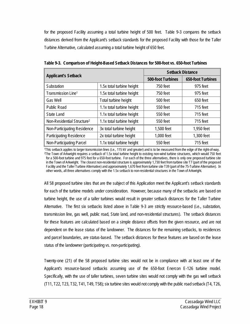
EXHIBIT 9 Cassadaga Wind LLC Page 18 Cassadaga Wind Project
for the proposed Facility assuming a total turbine height of 500 feet. Table 9-3 compares the setback
distances derived from the Applicant’s setback standards for the proposed Facility with those for the Taller
Turbine Alternative, calculated assuming a total turbine height of 650 feet.
Table 9-3. Comparison of Height-Based Setback Distances for 500-foot vs. 650-foot Turbines
Applicant’s Setback Setback Distance
500-foot Turbines 650-foot Turbines
Substation 1.5x total turbine height 750 feet 975 feet
Transmission Line1 1.5x total turbine height 750 feet 975 feet
Gas Well Total turbine height 500 feet 650 feet
Public Road 1.1x total turbine height 550 feet 715 feet
State Land 1.1x total turbine height 550 feet 715 feet
Non-Residential Structure2 1.1x total turbine height 550 feet 715 feet
Non-Participating Residence 3x total turbine height 1,500 feet 1,950 feet
Participating Residence 2x total turbine height 1,000 feet 1,300 feet
Non-Participating Parcel 1.1x total turbine height 550 feet 715 feet 1This setback applies to larger transmission lines (i.e., 115 kV and greater) and is to be measured from the edge of the right-of-way. 2The Town of Arkwright requires a setback of 1.5x total turbine height to existing non-wind turbine structures, which would 750 feet
for a 500-foot turbine and 975 feet for a 650-foot turbine. For each of the three alternatives, there is only one proposed turbine site in the Town of Arkwright. The closest non-residential structure is approximately 1,730 feet from turbine site T7 (part of the proposed Facility and the Taller Turbine Alternative) and approximately 1,670 feet from turbine site T39 (part of the 75-Turbine Alternative). In other words, all three alternatives comply with the 1.5x setback to non-residential structures in the Town of Arkwright.
All 58 proposed turbine sites that are the subject of this Application meet the Applicant’s setback standards
for each of the turbine models under consideration. However, because many of the setbacks are based on
turbine height, the use of a taller turbines would result in greater setback distances for the Taller Turbine
Alternative. The first six setbacks listed above in Table 9-3 are strictly resource-based (i.e., substation,
transmission line, gas well, public road, State land, and non-residential structures). The setback distances
for these features are calculated based on a simple distance offsets from the given resource, and are not
dependent on the lease status of the landowner. The distances for the remaining setbacks, to residences
and parcel boundaries, are status-based. The setback distances for these features are based on the lease
status of the landowner (participating vs. non-participating).
Twenty-one (21) of the 58 proposed turbine sites would not be in compliance with at least one of the
Applicant’s resource-based setbacks assuming use of the 650-foot Enercon E-126 turbine model.
Specifically, with the use of taller turbines, seven turbine sites would not comply with the gas well setback
(T11, T22, T23, T32, T41, T49, T58); six turbine sites would not comply with the public road setback (T4, T26,
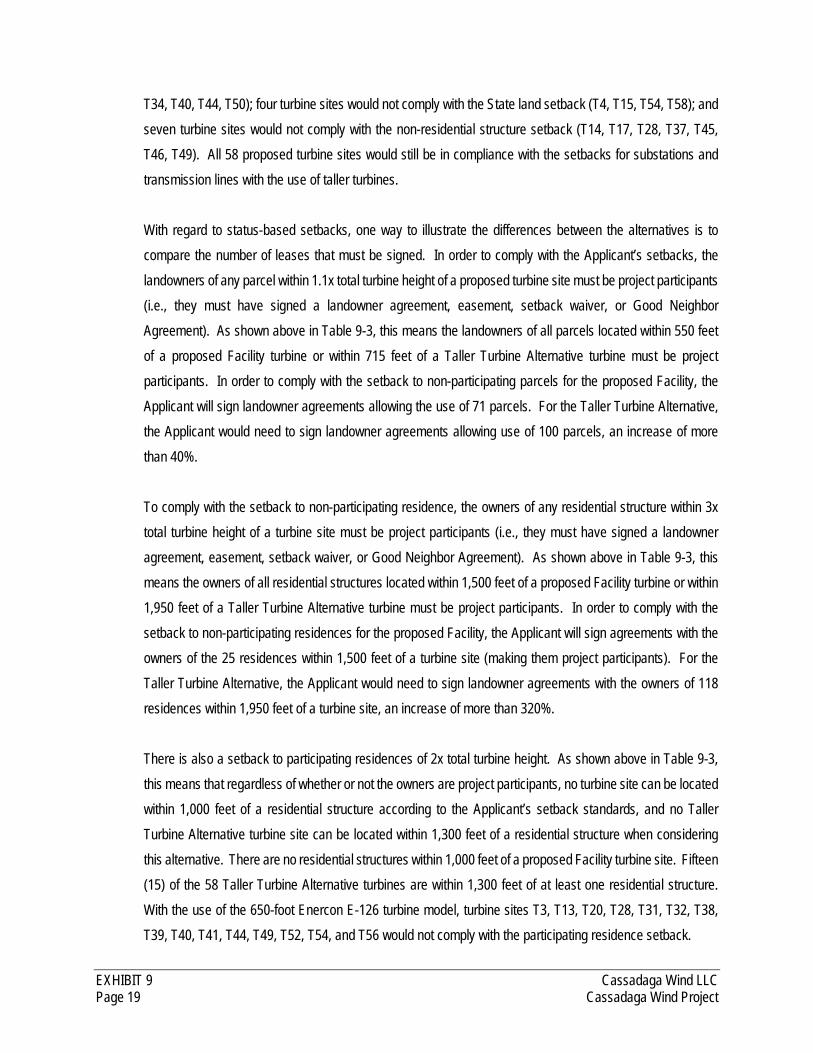
EXHIBIT 9 Cassadaga Wind LLC Page 19 Cassadaga Wind Project
T34, T40, T44, T50); four turbine sites would not comply with the State land setback (T4, T15, T54, T58); and
seven turbine sites would not comply with the non-residential structure setback (T14, T17, T28, T37, T45,
T46, T49). All 58 proposed turbine sites would still be in compliance with the setbacks for substations and
transmission lines with the use of taller turbines.
With regard to status-based setbacks, one way to illustrate the differences between the alternatives is to
compare the number of leases that must be signed. In order to comply with the Applicant’s setbacks, the
landowners of any parcel within 1.1x total turbine height of a proposed turbine site must be project participants
(i.e., they must have signed a landowner agreement, easement, setback waiver, or Good Neighbor
Agreement). As shown above in Table 9-3, this means the landowners of all parcels located within 550 feet
of a proposed Facility turbine or within 715 feet of a Taller Turbine Alternative turbine must be project
participants. In order to comply with the setback to non-participating parcels for the proposed Facility, the
Applicant will sign landowner agreements allowing the use of 71 parcels. For the Taller Turbine Alternative,
the Applicant would need to sign landowner agreements allowing use of 100 parcels, an increase of more
than 40%.
To comply with the setback to non-participating residence, the owners of any residential structure within 3x
total turbine height of a turbine site must be project participants (i.e., they must have signed a landowner
agreement, easement, setback waiver, or Good Neighbor Agreement). As shown above in Table 9-3, this
means the owners of all residential structures located within 1,500 feet of a proposed Facility turbine or within
1,950 feet of a Taller Turbine Alternative turbine must be project participants. In order to comply with the
setback to non-participating residences for the proposed Facility, the Applicant will sign agreements with the
owners of the 25 residences within 1,500 feet of a turbine site (making them project participants). For the
Taller Turbine Alternative, the Applicant would need to sign landowner agreements with the owners of 118
residences within 1,950 feet of a turbine site, an increase of more than 320%.
There is also a setback to participating residences of 2x total turbine height. As shown above in Table 9-3,
this means that regardless of whether or not the owners are project participants, no turbine site can be located
within 1,000 feet of a residential structure according to the Applicant’s setback standards, and no Taller
Turbine Alternative turbine site can be located within 1,300 feet of a residential structure when considering
this alternative. There are no residential structures within 1,000 feet of a proposed Facility turbine site. Fifteen
(15) of the 58 Taller Turbine Alternative turbines are within 1,300 feet of at least one residential structure.
With the use of the 650-foot Enercon E-126 turbine model, turbine sites T3, T13, T20, T28, T31, T32, T38,
T39, T40, T41, T44, T49, T52, T54, and T56 would not comply with the participating residence setback.

EXHIBIT 9 Cassadaga Wind LLC Page 20 Cassadaga Wind Project
The environmental impacts of constructing Enercon E-126 turbines would be similar to the impacts from
constructing the proposed Facility, because turbines, access roads, and collection lines would be sited in the
same locations. Wetland and stream impacts would be very similar, because turbine sites have been selected
to avoid impacts to such resources. However, permanent soil, vegetation, land use, and agricultural impacts
would be somewhat greater, because the Enercon E-126 turbine has a larger tower diameter at the base and
requires a larger foundation.
The Taller Turbine Alternative is not preferred because the greater height results in proportionally larger
setbacks, which would make it extremely difficult to reach a total generating capacity of 126 MW. The 650-
foot height would also violate the maximum total turbine height restrictions in all of the host Towns.
75-Turbine Alternative
This alternative explores the option of utilizing 75 proposed turbine sites instead of 58, using the same range
of turbine models under consideration for the proposed Facility. Some of the turbine sites in the 75-Turbine
Alternative are located in the same general areas as proposed Facility turbine sites (due to the availability of
wind resources), while others are located along completely different ridgelines. Table 9-4 identifies the
position of the 75-Turbine Alternative turbine sites. See also Figure 3-1.
Table 9-4. Turbine Coordinates, 75-Turbine Alternative
Turbine ID Latitude Longitude Turbine ID Latitude Longitude
1 42.27067 -79.12278 39 42.35067 -79.24488
2 42.31619 -79.11782 40 42.31939 -79.16897
3 42.27339 -79.12457 41 42.33516 -79.23063
4 42.32304 -79.12687 42 42.34106 -79.19686
5 42.32522 -79.14899 43 42.26578 -79.18813
6 42.26250 -79.17387 44 42.30543 -79.14969
7 42.28163 -79.26977 45 42.28281 -79.14220
8 42.26073 -79.17027 46 42.30894 -79.15565
9 42.27648 -79.13754 47 42.32938 -79.22738
10 42.32741 -79.17786 48 42.33827 -79.14972
11 42.31885 -79.12043 49 42.31618 -79.16571
12 42.29096 -79.26318 50 42.29400 -79.18559
13 42.27606 -79.12747 51 42.30718 -79.15273
14 42.32101 -79.12365 52 42.33008 -79.13899

EXHIBIT 9 Cassadaga Wind LLC Page 21 Cassadaga Wind Project
Turbine ID Latitude Longitude Turbine ID Latitude Longitude
15 42.34540 -79.24243 53 42.27438 -79.20235
16 42.29768 -79.16784 54 42.31048 -79.20601
17 42.27137 -79.13092 55 42.30031 -79.21574
18 42.28940 -79.27315 56 42.29809 -79.18750
19 42.26368 -79.18453 57 42.27004 -79.19537
20 42.32556 -79.17387 58 42.33339 -79.21723
21 42.33412 -79.15683 59 42.26356 -79.19530
22 42.29464 -79.26256 60 42.26850 -79.20281
23 42.27383 -79.13415 61 42.33510 -79.14461
24 42.31048 -79.15881 62 42.26783 -79.19150
25 42.33092 -79.15450 63 42.29407 -79.21385
26 42.33811 -79.23258 64 42.26558 -79.19968
27 42.30030 -79.17138 65 42.27258 -79.19822
28 42.28695 -79.26920 66 42.30794 -79.20327
29 42.28053 -79.13364 67 42.33252 -79.14194
30 42.26433 -79.17737 68 42.27894 -79.14011
31 42.29774 -79.26490 69 42.27730 -79.20569
32 42.33224 -79.22912 70 42.31545 -79.19518
33 42.28356 -79.13571 71 42.32782 -79.20430
34 42.33844 -79.19375 72 42.33588 -79.22002
35 42.32801 -79.15179 73 42.33280 -79.20416
36 42.34798 -79.24401 74 42.31275 -79.19217
37 42.27821 -79.13097 75 42.33855 -79.22327
38 42.31316 -79.17100
Because the setbacks are height-based, the same setback distances presented above in Table 9-3 for the
proposed Facility also apply to the 75-Turbine Alternative.
Nineteen (19) of the 75 sites would not be in compliance with at least one of the resource-based setbacks
with the use of the same turbine models under consideration for the proposed Facility. Specifically, with the
75-Turbine Alternative, nine turbine sites would violate the public road setback (T24, T34, T38, T42, T44, T45,
T46, T51, T56); seven turbine sites would violate the State land setback (T10, T34, T38, T40, T42, T50, T74);
and eight turbine sites would violate the non-residential structure setback (T11, T12, T14, T18, T29, T44, T45,
T64). By comparison, all 58 proposed Facility turbine sites will meet or exceed these setbacks. All 75
EXHIBIT 9 Cassadaga Wind LLC Page 22 Cassadaga Wind Project
alternative turbine sites would be in compliance with the setbacks for substations, transmission lines, and gas
wells.
In order to comply with the setback to non-participating parcels for the 75-Turbine Alternative, the owners of
all parcels located within 550 feet of a turbine must be project participants. To achieve this, the Applicant
would need to sign agreements/waivers/easements allowing the use of 119 parcels. This represents an
increase of more than 67% when compared to the 71 landowner agreements required to comply with the
setback to non-participating parcels for the proposed Facility.
In order to comply with the setback to non-participating residences for the 75-Turbine Alternative, the owners
of all residential structures located within 1,500 feet of a turbine must be project participants. To achieve this,
the Applicant would need to sign landowner agreements with the owners of 82 residences. This represents
an increase of more than 192% when compared to the 28 landowner agreements required to comply with the
setback to non-participating residences for the proposed Facility.
In order to comply with the setback to participating residences for the 75-Turbine Alternative, no turbine sites
can be located within 1,000 feet of a residential structure. A total of seven 75-Turbine Alternative turbine sites
would not comply with the participating residence setback: T6, T8, T16, T26, T44, T56, and T74. By
comparison, there are no residential structures within 1,000 feet of a proposed Facility turbine site.
Field reconnaissance conducted on the 75-turbine layout in April 2015 determined that stream and wetland
impacts would be significantly greater under this scenario, more so than would be expected proportionally
based on the increase to 75 turbine sites (an increase of 29 percent compared to the 58 turbine sites for the
proposed Facility). Approximately 4.77 acres of wetlands and 604 linear feet of streams would be permanently
impacted by the 75-Turbine Alternative, increases of 208 and 77 percent, respectively, when compared to the
proposed Facility. See Exhibit 22 of this Application for more detailed information on impacts to wetlands and
streams from the proposed Facility. It also appears that impacts to archaeological resources could not be
entirely avoided with the 75-Turbine Alternative. This is because when siting a larger number of turbines,
there is less opportunity for avoiding impacts to sensitive resources (e.g., wetlands, cultural resources) without
creating wake effects between turbines or impacting other sensitive resources. Visual, sound, and shadow
flicker impacts also could not be minimized in the 75-Turbine Alternative to the extent that they have in the
proposed Facility layout.
EXHIBIT 9 Cassadaga Wind LLC Page 23 Cassadaga Wind Project
The 75-Turbine Alternative is not preferred because the impacts from this layout are so much greater. The
smaller layout associated with the proposed Facility allows greater flexibility in minimizing impacts to nearby
residents, as well as to sensitive resources such as wetlands, streams, and cultural resources.
(5) Timing of In-service Date in Relation to Other Capacity Changes to the Electric System
Siemens Power Technologies International prepared a System Reliability Impact Study (SRIS) for the Project
on behalf of the New York Independent System Operator (NYISO) in 2015. The SRIS is Appendix E to this
Application, but will be filed under confidential cover, as NYISO requires the SRIS to remain confidential due
to Critical Energy Infrastructure Information (CEII) Regulations.
The SRIS evaluated a number of power flow base cases, as provided by the NYISO, including 2018 summer
peak, winter peak, and light load. In base case normal operating conditions, the power flow steady state
analyses indicate that the Project will cause no thermal violations for summer peak and winter peak case
loadings. Under contingency operating conditions with the Project, the summer peak case shows some
overloads on the 230 kV and 115 kV lines under several contingencies. The addition of the Project reduced
the overload on these lines, thus causing a positive impact on the system. The addition of the Project
increased the 34.5 kV post-contingency voltage by as much as 2% and exceeded its 105% limit. Post-
contingency load tap changes in the 115/34.5 kV transformers reduced the 34.5 kV voltages to acceptable
levels.
For the winter peak case, the Project caused an adverse impact of about 11% on the Hartfield 115/34.5 kV
transformer following the double circuit contingency. However, this overload can be mitigated by the
construction of a new sub-T station ‘West Asheville’ (115-34.5kV 25 MVA), located at the junction of Dunkirk-
Falconer Line 160 and Sherman-Ashville Line 863, a reliability project approved by National Grid. Hence, the
Project does not require any additional network upgrades for interconnection. Voltage violations at some
buses near the point of interconnection also occurred under several contingencies with the addition of the
Project, but as with the summer peak case, load tap changes in the 115/34.5 kV transformers reduced most
of the 34.5 kV voltage to acceptable levels (Siemens PTI, 2015).
Based upon the findings in the SRIS, this Facility is not anticipated to have any adverse effects on the New
York State Power Grid. Please see Exhibit 5 of this Application for additional information.

EXHIBIT 9 Cassadaga Wind LLC Page 24 Cassadaga Wind Project
(d) Why the Proposed Location Best Promotes Public Health and Welfare
The proposed location is best suited to promote public health and welfare because it properly balances the siting
constraints discussed above with the public health benefits of wind energy generation. Air pollution has both short-
term and long-term adverse effects on public health. Electricity generated from zero-emission wind energy facilities
like the proposed Facility can displace the electricity generated from conventional power plants, thereby reducing the
emissions of conventional air pollutants, such as mercury; sulfur and nitrogen oxides; and carbon dioxide. Less fossil
fuel combustion will improve public health and welfare. Commercial scale wind power projects can only be sited in
certain locations that are conducive to wind energy production. The Applicant selected the proposed site for the Facility
because of the presence of the wind resource, the presence of available land and willing landowners, the relative ease
of access to the site, and the proximity and relative ease of connecting to the existing electric transmission grid. These
factors combined to make the proposed site best suited for wind power development and the associated beneficial
impacts to air quality.
(e) Why the Proposed Technology, Scale, and Timing Best Promote Public Health and Welfare
The benefits of the Facility are anticipated to include positive impacts on socioeconomics (e.g., increased employment,
increased revenues to local municipalities and lease revenues to participating landowners and neighbors), air quality
(through reduction of emissions from fossil-fuel-burning power plants), and climate (reduction of greenhouse gases
that contribute to global warming). By eliminating pollutants and greenhouse gases, the Facility will also benefit
ecological and water resources and human health.
The proposed technology, scale, and timing of the Facility are best suited to promote public health and welfare. The
turbines proposed for the Facility will utilize the latest in wind power generation technology to enhance project efficiency
and safety, and minimize impacts such as noise. If the scale of the proposed Facility (i.e., generating capacity) were
significantly reduced, the maximum benefit of the available wind resource would not be realized, thereby reducing
economic and public health benefits. If the proposed number of turbines were significantly increased above the 58
sites evaluated in this Application, the Applicant would need more land area to meet the siting criteria, which is not
feasible because the Applicant does not have additional land under lease option.
Regarding timing, the State Energy Plan calls for achieving a 40% reduction in GHG emissions from 1990 levels and
50% of generation of electricity from renewable energy sources by 2030 (NYSEPB, 2015). These are aggressive
targets that will require significant new sources of renewable energy be brought online as soon as possible.
Furthermore, New York State is already experiencing adverse impacts from climate change, including rising
EXHIBIT 9 Cassadaga Wind LLC Page 25 Cassadaga Wind Project
temperatures and sea levels, decreased winter snow cover, more intense precipitation events, more extreme summer
heat waves, and more widespread vector-borne infections and diseases. However, according to the NYSDEC (2016c),
it’s not too late: “If we reduce emissions in the near future, future risk from climate change will be lower. Failure to
reduce emissions now will compound future change, making impacts even more disruptive and costly.” Therefore, the
timing of the Facility best promotes public health and welfare.
(f) No Action Alternative
The no action alternative assumes that the Facility Site would continue to exist as is. This no action alternative would
not beneficially nor adversely affect current land use, ambient noise conditions, traffic or public road conditions,
television/communication systems, and would maintain the area’s current community character, socioeconomic, and
energy-generating conditions as they currently exist.
The No Action Alternative is not best suited to promote public health, because it would deprive the state and the region
with a source of clean, pollutant-free electricity. The operating Facility will generate up to 126 MW of electricity without
emitting pollutants or heat-trapping greenhouse gases. Air pollution is generated by many human activities, including
manufacturing, vehicle exhaust, and energy facilities that burn coal, gas, or oil. Air pollution has both short-term and
long-term adverse effects on public health. Short-term exposure to air pollution caused by fossil-fueled electricity
generation may result in headaches, nausea, allergic reactions, asthma exacerbation, and irritation to the eyes, nose
and throat. Long-term exposures can lead to cancer, as well as a variety of adverse reproductive, development,
respiratory, and cardiovascular effects (NYSDEC, 2016a).
According to the NYSDEC (2016b), “For a sustainable future, we need an efficient energy system that taps clean
sources to let us enjoy energy's benefits, but use less and pay less. Solar and wind energy, geothermal heat and other
renewable resources can power our lives with no cost for fuel and no harmful emissions. An efficient system with
reliable and affordable clean energy already is demonstrating its potential to support an abundant and sustainable New
York:
Energy efficiency improvements and renewable sources are cutting consumers' carbon footprints, making
communities cleaner and healthier, and supporting local economies.
Electricity from renewable sources is helping to create a more resilient and flexible power grid with less
reliance on expensive peaking power.
New York businesses that provide clean energy products and services are responding to growing markets
with expanded offerings and good jobs.”

EXHIBIT 9 Cassadaga Wind LLC Page 26 Cassadaga Wind Project
As indicated above, electricity generated from zero-emission wind energy facilities like the proposed Facility can
displace the electricity generated from conventional power plants, thereby reducing the emissions of conventional air
pollutants, such as mercury; sulfur and nitrogen oxides (acid rain precursors); and carbon dioxide (linked to global
climate change). On a long-term basis, increasing the production of wind generated power will reduce the need to
construct and operate new fossil fueled power plants (Jacobsen & High, 2008).
Furthermore, the No Action Alternative is not best suited to promote public welfare, because it would deprive the state
of a new source of renewable energy that would help achieve the objectives of the State Energy Plan, the Governor’s
Reforming the Energy Vision (REV) Strategy, and the Clean Energy Standard (CES). The 2015 State Energy Plan
contains a series of policy objectives to increase the use of energy systems that enable the State to significantly reduce
greenhouse gas (GHG) emissions while stabilizing energy costs. The State Energy Plan commits to achieving a 40%
reduction in GHG emissions from 1990 levels by 2030 and reducing total carbon emissions 80% by 2050. In addition,
the State Energy Plan calls for 50% of generation of electricity from renewable energy sources by 2030 (NYSEPB,
2015). The No Action Alternative would not help advance the objectives of the State Energy Plan (i.e., it would not
contribute toward reducing GHG emissions or assist the State in achieving the 50% renewable energy generation
objective).
REV is a strategy to build a clean, resilient, and affordable energy system for all New Yorkers. The Public Service
Commission (PSC) issued their Order Adopting Regulatory Policy Framework and Implementation Plan on February
26, 2015 that outlines issues and tasks to resolve the technical, marketplace, and regulatory challenges necessary to
achieve the REV plan and goals. As stated by the PSC in the REV Order, “A significant increase in the penetration of
renewable resources is essential to meeting our objectives, state goals and proposed federal requirements” (PSC,
2015). The REV Order recognizes that large-scale renewables (LSR), such as the proposed Facility, will be critically
important to meeting greenhouse gas emissions reduction goals. On December 2, 2015, Governor Andrew Cuomo
directed the Department of Public Service to develop a CES, which would change the targets identified in the State
Energy Plan to required mandates. The No Action Alternative would not contribute to State policy objectives, because
it would not provide additional electrical capacity produced by renewable energy.
(g) Energy Supply Source Alternatives
Because different energy supplies do not meet the objectives or capabilities of the Applicant, no alternative energy
supply sources have been identified. Therefore, alternative energy supply sources will not be evaluated in this
Application.
EXHIBIT 9 Cassadaga Wind LLC Page 27 Cassadaga Wind Project
(h) Comparison of Advantages and Disadvantages of Proposed and Alternative Energy Sources
Because source and demand-reducing alternatives do not meet the objectives or capabilities of the Applicant, no
alternatives have been identified. Therefore, source and demand – reducing alternatives will not be evaluated in this
Application.
(i) Why the Proposed Facility Best Promotes Public Health and Welfare
The Applicant has designed the Facility layout to optimize the balance between energy generation and the protection
of agricultural, environmental, and aesthetic resources, as well as public health and welfare. The design of the Facility
has evolved through an iterative process that incorporates various siting constraints, including wind resource;
landowner considerations; stream, wetland, and cultural resources impact avoidance/minimization; noise and shadow
flicker minimization; and protection of agricultural lands. Each of these issues are discussed in detail in this Application
(e.g., see Exhibits 19, 22, 23, and 24). Alternative layouts at the same Facility Site were evaluated above, and the
Facility, as proposed, is the best suited to promote public health and welfare.

EXHIBIT 9 Cassadaga Wind LLC Page 28 Cassadaga Wind Project
REFERENCES
American Wind Energy Association (AWEA). 2015. Wind Energy Industry Announces New Voluntary Practices to Reduce Overall Impacts to Bats by 30 Percent. Press Release. Available at: http://www.awea.org/Media Center/pressrelease.aspx?ItemNumber=7833 (Accessed February 2016). AWS Truewind. 2007. Wind Resource of New York: Mean Annual Wind Speed at 100 Meters. GZA GeoEnvironmental of New York (GZA). 2015. Preliminary Geotechnical Assessment, Proposed Cassadaga Wind Farm Project, Chautauqua County, New York. Prepared for EverPower. December 15, 2015. Iverson, L., A. Prasad and S. Matthews. 2008. Potential Changes in Suitable Habitat for 134 Tree Species in the Northeastern United States. Mitigation and Adaptation Strategies of Global Change 13: 487–516. Jacobi, R. D. 2002. Basement Faults and Seismicity in the Appalachian Basin of New York State. Tectonophysics 353: 75-113. Jacobsen, D. and C. High. 2008. Wind Energy and Air Emissions Reduction Benefits: A Primer. U.S. Department of Energy, Office of Energy Efficiency and Renewable Energy, National Renewable Energy Laboratory. Golden, CO. NREL/SR-500-42616. February 2008. National Renewable Energy Laboratory (NREL) and AWS Truepower. New York Annual Average Wind Speed at 80 m. November 2, 2010. New York State Department of Environmental Conservation (NYSDEC). 2016a. Controlling Sources of Toxic Air Pollutants. Available at: http://www.dec.ny.gov/chemical/89934.html (Accessed February 2016). NYSDEC. 2016b. Mitigation of Climate Change: Rethinking Our Energy Sources. Available at: http://www.dec. ny.gov/energy/99223.html (Accessed February 2016). NYSDEC. 2016c. Impacts of Climate Change in New York: Already Happening, But It’s Not Too Late. Available at: http://www.dec.ny.gov/energy/94702.html (Accessed April 2016). New York State Energy Planning Board (NYSEPB). 2015. 2015 New York State Energy Plan. June 25, 2015. New York State Energy Research and Development Authority (NYSERDA). 2011. Responding to Climate Change in New York State: The ClimAID Integrated Assessment for Effective Climate Change Adaptation in New York State. NYSERDA Report 11-18, November 2011. NYSERDA. 2014. Climate Change in New York State: Updating the 2011 ClimAID Climate Risk Information, Supplement to the NYSERDA Report 11-18. NYSERDA Report 14-26, September 2014. Puglia, P. S. 1994. Soil Survey of Chautauqua County, New York. United States Department of Agriculture Soil Conservation Service in cooperation with Cornell University Agricultural Experiment Station. Available at: http://www.nrcs.usda.gov/Internet/FSE_MANUSCRIPTS/new_york/NY013/0/chautauqua.pdf (Accessed April 2015) Siemens Power Technologies International. 2015. Cassadaga Wind Project System Reliability Impact Study – NYISO Queue #387. Prepared for the New York Independent System Operator. Rev. 4, January 19, 2015.

EXHIBIT 9 Cassadaga Wind LLC Page 29 Cassadaga Wind Project
U.S. Energy Information Administration (USEIA). 2015. Electric Sales, Revenue, and Average Price: 2014 Average Monthly Bill – Residential. Data from Forms EIA-864 schedules 4A-D, EIA-861S, and EIA-861U. Available at: http://www.eia.gov/electricity/sales_revenue_price/pdf/table5_a.pdf (Accessed February 2016). U.S. Environmental Protection Agency (USEPA). 2015a. eGRID Subregion Output Emission Rates. Available at: http://www2.epa.gov/sites/production/files/2015-10/documents/egrid2012_summarytables_0.pdf (Accessed March, 2016). USEPA. 2015b. State Carbon Dioxide Emissions – New York State. Released October 26, 2015. Available at: http://www.eia.gov/environment/emissions/state/ (Accessed March, 2016). United States Geological Service (USGS). 2014. New York State 2014 Seismic Hazard Map. USGS National Seismic Hazard Maps. Available at: http://earthquake.usgs.gov/earthquakes/states/new_york/hazards.php (Last updated October 2014; Accessed February 2016). USGS. 2015. New York Earthquake History. USGS Earthquake Hazards Program. Available at: http://earthquake. usgs.gov/earthquakes/states/new_york/history.php (Last updated January 2015; Accessed February 2016).