exp3 lan switching ch02-tonychen
TRANSCRIPT

5/9/2018 Exp3 LAN Switching Ch02-TonyChen - slidepdf.com
http://slidepdf.com/reader/full/exp3-lan-switching-ch02-tonychen 1/89
© 2006 Cisco Systems, Inc. Al l r ights reserved. Cisco Publ icITE I Chapter 6 1
Configure a Switch
LAN Switching and Wireless – Chapter 2Modified by Tony Chen
04/20/2008

5/9/2018 Exp3 LAN Switching Ch02-TonyChen - slidepdf.com
http://slidepdf.com/reader/full/exp3-lan-switching-ch02-tonychen 2/89
© 2006 Cisco Systems, Inc. Al l r ights reserved. Cisco Publ icITE 1 Chapter 6 2
Notes:
If you see any mistake on my PowerPoint slides or ifyou have any questions about the materials, pleasefeel free to email me at [email protected].
Thanks!
Tony Chen
College of DuPage
Cisco Networking Academy

5/9/2018 Exp3 LAN Switching Ch02-TonyChen - slidepdf.com
http://slidepdf.com/reader/full/exp3-lan-switching-ch02-tonychen 3/89
© 2006 Cisco Systems, Inc. Al l r ights reserved. Cisco Publ icITE 1 Chapter 6 3
Objectives
Summarize the operation of Ethernet as defined for100/1000 Mbps LANs in the IEEE 802.3 standard.
Explain the functions that enable a switch to forwardEthernet frames in a LAN.
Configure a switch for operation in a networkdesigned to support voice, video, and datatransmissions.
Configure basic security on a switch that will operatein a network designed to support voice, video, anddata transmissions.

5/9/2018 Exp3 LAN Switching Ch02-TonyChen - slidepdf.com
http://slidepdf.com/reader/full/exp3-lan-switching-ch02-tonychen 4/89
© 2006 Cisco Systems, Inc. Al l r ights reserved. Cisco Publ icITE 1 Chapter 6 4
key elements of Ethernet/802.3 networks CSMA/CD
–Ethernet signals are transmittedto every host connected to theLAN using a special set of rulesto determine which station canaccess the network.
–The set of rules that Ethernetuses is based on the IEEE carriersense multiple access/collisiondetect (CSMA/CD) technology.
–Note: CSMA/CD is only used
with half-duplex communicationtypically found in hubs. Full-duplex switches do not useCSMA/CD.
(JAM) When a collisionoccurs, each node thatis transmitting willcontinue to transmit fora short time to ensurethat all devices see the
collision.
The devices that wereinvolved in the collision do
not have priority to transmitdata.

5/9/2018 Exp3 LAN Switching Ch02-TonyChen - slidepdf.com
http://slidepdf.com/reader/full/exp3-lan-switching-ch02-tonychen 5/89
© 2006 Cisco Systems, Inc. Al l r ights reserved. Cisco Publ icITE 1 Chapter 6 5
key elements of Ethernet/802.3 networks Carrier Sense
–In CSMA/CD, all devices that have messages
to send must listen before transmitting.•If a device detects a signal from another device, itwaits before attempting to transmit.
•When there is no traffic detected, a devicetransmits its message.
•While this transmission is occurring, the devicecontinues to listen for traffic on the LAN.
•After the message is sent, the device returns toits default listening mode.
Multi-access –If the signals of one device are not detected bya second device, the second device may alsostart to transmit.
•The media now has two devices transmittingsignals at the same time.
•The messages propagate across the media untilthey encounter each other.
•At that point, the signals mix and the messagesare destroyed, a collision.
•Although the messages are corrupted, the
remaining signals continues to propagate acrossthe media.
5/9/2018 Exp3 LAN Switching Ch02-TonyChen - slidepdf.com
http://slidepdf.com/reader/full/exp3-lan-switching-ch02-tonychen 6/89
© 2006 Cisco Systems, Inc. Al l r ights reserved. Cisco Publ icITE 1 Chapter 6 6
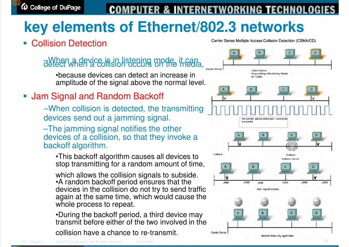
key elements of Ethernet/802.3 networks Collision Detection
–When a device is in listening mode, it candetect when a collision occurs on the media,
•because devices can detect an increase inamplitude of the signal above the normal level.
Jam Signal and Random Backoff
–When collision is detected, the transmittingdevices send out a jamming signal.
–The jamming signal notifies the otherdevices of a collision, so that they invoke abackoff algorithm.
•This backoff algorithm causes all devices tostop transmitting for a random amount of time,
which allows the collision signals to subside.•A random backoff period ensures that thedevices in the collision do not try to send trafficagain at the same time, which would cause thewhole process to repeat.
•During the backoff period, a third device maytransmit before either of the two involved in the
collision have a chance to re-transmit.

5/9/2018 Exp3 LAN Switching Ch02-TonyChen - slidepdf.com
http://slidepdf.com/reader/full/exp3-lan-switching-ch02-tonychen 7/89
© 2006 Cisco Systems, Inc. Al l r ights reserved. Cisco Publ icITE 1 Chapter 6 7
key elements of Ethernet/802.3 networksCSMA/CD
http://en.wikipedia.org/wiki/Carrier_sense_multiple_access_with_collision_detection
5/9/2018 Exp3 LAN Switching Ch02-TonyChen - slidepdf.com
http://slidepdf.com/reader/full/exp3-lan-switching-ch02-tonychen 8/89
© 2006 Cisco Systems, Inc. Al l r ights reserved. Cisco Publ icITE 1 Chapter 6 8
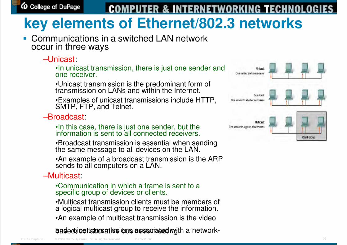
key elements of Ethernet/802.3 networks Communications in a switched LAN network
occur in three ways
–Unicast:•In unicast transmission, there is just one sender andone receiver.
•Unicast transmission is the predominant form oftransmission on LANs and within the Internet.
•Examples of unicast transmissions include HTTP,SMTP, FTP, and Telnet.
–Broadcast:•In this case, there is just one sender, but theinformation is sent to all connected receivers.
•Broadcast transmission is essential when sendingthe same message to all devices on the LAN.
•An example of a broadcast transmission is the ARPsends to all computers on a LAN.
–Multicast:•Communication in which a frame is sent to aspecific group of devices or clients.
•Multicast transmission clients must be members ofa logical multicast group to receive the information.
•An example of multicast transmission is the video
and voice transmissions associated with a network-based, collaborative business meeting.
5/9/2018 Exp3 LAN Switching Ch02-TonyChen - slidepdf.com
http://slidepdf.com/reader/full/exp3-lan-switching-ch02-tonychen 9/89 © 2006 Cisco Systems, Inc. Al l r ights reserved. Cisco Publ icITE 1 Chapter 6 9
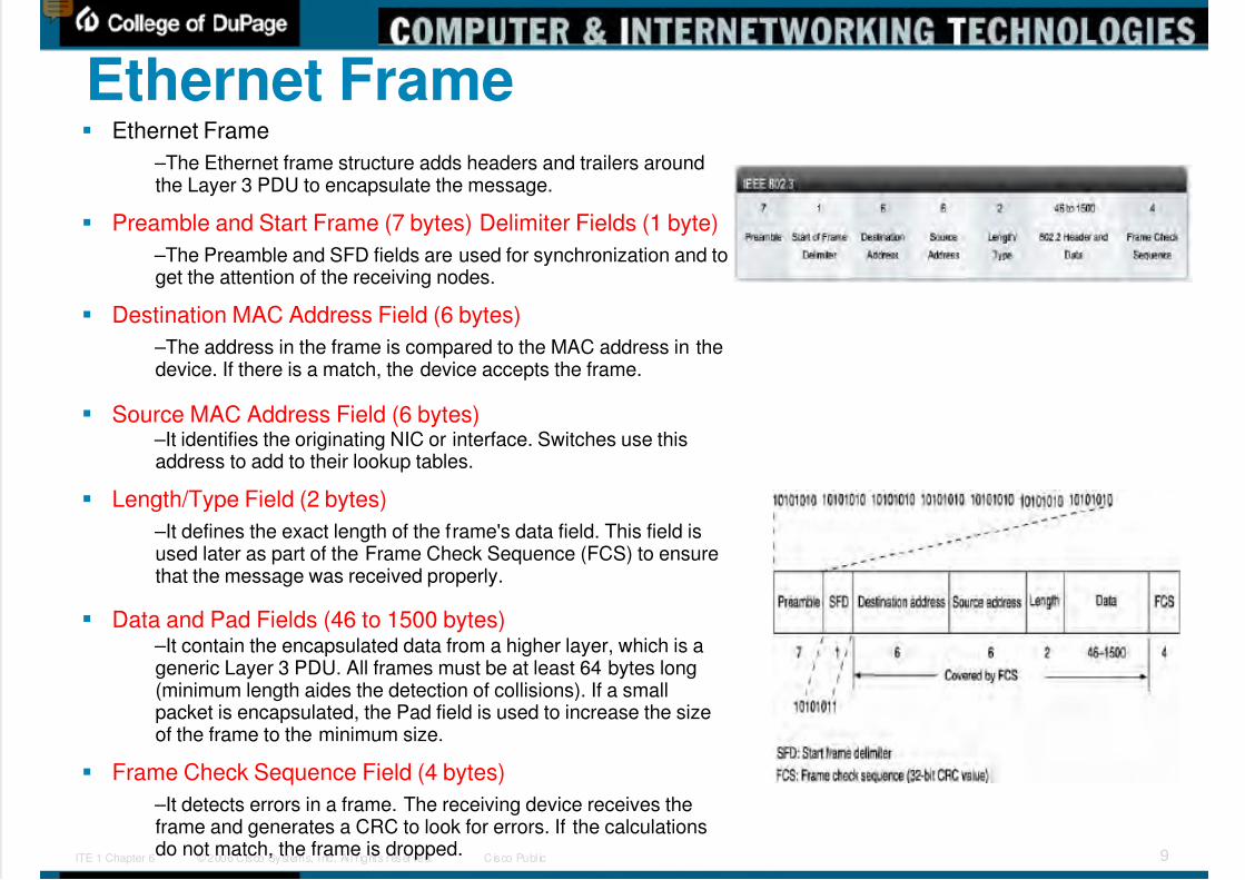
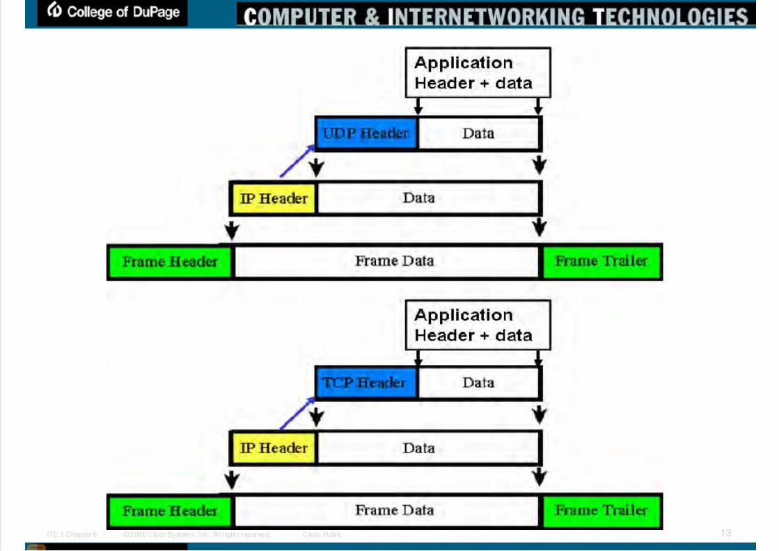
Ethernet Frame Ethernet Frame
–The Ethernet frame structure adds headers and trailers aroundthe Layer 3 PDU to encapsulate the message.
Preamble and Start Frame (7 bytes) Delimiter Fields (1 byte)
–The Preamble and SFD fields are used for synchronization and toget the attention of the receiving nodes.
Destination MAC Address Field (6 bytes)
–The address in the frame is compared to the MAC address in thedevice. If there is a match, the device accepts the frame.
Source MAC Address Field (6 bytes) –It identifies the originating NIC or interface. Switches use thisaddress to add to their lookup tables.
Length/Type Field (2 bytes)
–It defines the exact length of the frame's data field. This field isused later as part of the Frame Check Sequence (FCS) to ensurethat the message was received properly.
Data and Pad Fields (46 to 1500 bytes) –It contain the encapsulated data from a higher layer, which is ageneric Layer 3 PDU. All frames must be at least 64 bytes long(minimum length aides the detection of collisions). If a smallpacket is encapsulated, the Pad field is used to increase the sizeof the frame to the minimum size.
Frame Check Sequence Field (4 bytes)
–It detects errors in a frame. The receiving device receives theframe and generates a CRC to look for errors. If the calculationsdo not match, the frame is dropped.
5/9/2018 Exp3 LAN Switching Ch02-TonyChen - slidepdf.com
http://slidepdf.com/reader/full/exp3-lan-switching-ch02-tonychen 10/89 © 2006 Cisco Systems, Inc. Al l r ights reserved. Cisco Publ icITE 1 Chapter 6 10
Ethernet auto-negotiationEach Ethernet frame (or packet ) starts out with a sequence of bits thatalternate between 1 and 0 that looks like this: 1010101010101010....Each value (1 or 0) is represented by a specific state change, so whenthese bits are transmitted, the electrical signal on the Ethernet mediatransitions from "high" to "low" and back at the same speed the bits arebeing transmitted.
To determine the speed, the interface needs to measure only the timebetween the transitions.
If an interface is not capable of doing a higher speed, the bit pattern will look
like signal noise, just like human speech played at ten times the normal speedsounds like noise.
If each interface starts at its highest speed and works down, it can sync tothe first speed it understands from the other side.
This passive system allows the interfaces to determine a common speedvery quickly with a great deal of reliability. It is also worth pointing outthat the contents and format of the data that is sent is irrelevant, just the
fact that the data is sent.
The only way to detect, or attempt to guess, if the other side of a link cando full-duplex or not is to start transmitting something as soon as youstart to receive a signal from the other end.The other side will start toreceive your transmission before finishing up their own.
If the other side is happy with this, it must be in full-duplex mode.
If the other side thinks a collision has taken place, you know the otherinterface is in half-duplex mode.

5/9/2018 Exp3 LAN Switching Ch02-TonyChen - slidepdf.com
http://slidepdf.com/reader/full/exp3-lan-switching-ch02-tonychen 11/89 © 2006 Cisco Systems, Inc. Al l r ights reserved. Cisco Publ icITE 1 Chapter 6 11
Ethernet auto-negotiationDue to the problems with the older auto-sensingschemes (and the less than perfect ability of auto-
negotiation to get things correct), many people havegotten in the habit of "forcing" an interface into aspecific mode.
In general, it is standard practice here at the Universityof Illinois U-C campus to hand configure all switchuplink interfaces and router interfaces to a specificmode of operation, and not rely on any of the auto-negotiating or auto-sensing systems.
http://www.cites.uiuc.edu/network/advanced/autosense.html

5/9/2018 Exp3 LAN Switching Ch02-TonyChen - slidepdf.com
http://slidepdf.com/reader/full/exp3-lan-switching-ch02-tonychen 12/89 © 2006 Cisco Systems, Inc. Al l r ights reserved. Cisco Publ icITE 1 Chapter 6 12
Ethernet errors When transmitting smaller data packets, a Pad field
must be added to bring the total size of the Ethernetpacket up to at least 64 bytes.
http://www.techfest.com/networking/lan/ethernet2.htm
5/9/2018 Exp3 LAN Switching Ch02-TonyChen - slidepdf.com
http://slidepdf.com/reader/full/exp3-lan-switching-ch02-tonychen 13/89 © 2006 Cisco Systems, Inc. Al l r ights reserved. Cisco Publ icITE 1 Chapter 6 13
5/9/2018 Exp3 LAN Switching Ch02-TonyChen - slidepdf.com
http://slidepdf.com/reader/full/exp3-lan-switching-ch02-tonychen 14/89 © 2006 Cisco Systems, Inc. Al l r ights reserved. Cisco Publ icITE 1 Chapter 6 14
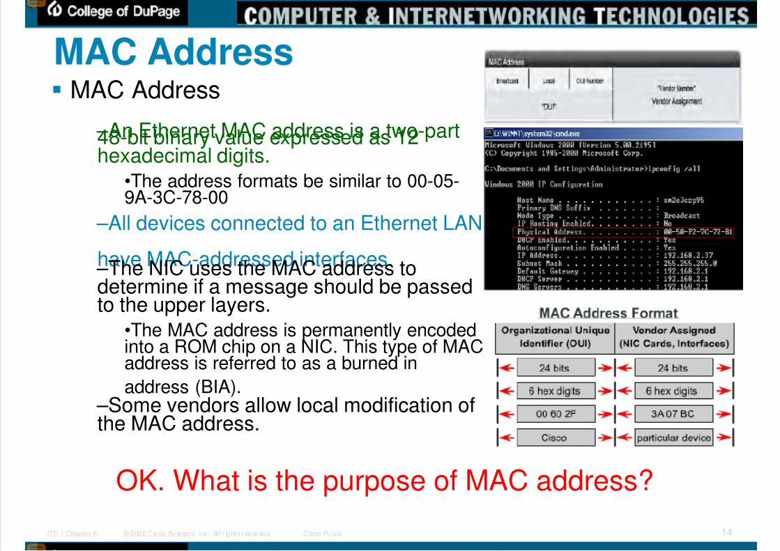
MAC Address MAC Address
–An Ethernet MAC address is a two-part48-bit binary value expressed as 12hexadecimal digits.
•The address formats be similar to 00-05-9A-3C-78-00
–All devices connected to an Ethernet LAN
have MAC-addressed interfaces. –The NIC uses the MAC address todetermine if a message should be passedto the upper layers.
•The MAC address is permanently encodedinto a ROM chip on a NIC. This type of MACaddress is referred to as a burned in
address (BIA). –Some vendors allow local modification ofthe MAC address.
OK. What is the purpose of MAC address?
5/9/2018 Exp3 LAN Switching Ch02-TonyChen - slidepdf.com
http://slidepdf.com/reader/full/exp3-lan-switching-ch02-tonychen 15/89 © 2006 Cisco Systems, Inc. Al l r ights reserved. Cisco Publ icITE 1 Chapter 6 15
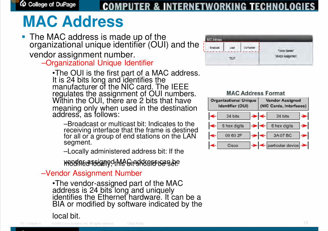
MAC Address The MAC address is made up of the
organizational unique identifier (OUI) and thevendor assignment number.
–Organizational Unique Identifier
•The OUI is the first part of a MAC address.It is 24 bits long and identifies themanufacturer of the NIC card. The IEEEregulates the assignment of OUI numbers.Within the OUI, there are 2 bits that havemeaning only when used in the destinationaddress, as follows:
–Broadcast or multicast bit: Indicates to thereceiving interface that the frame is destinedfor all or a group of end stations on the LANsegment.
–Locally administered address bit: If the
vendor-assigned MAC address can bemodified locally, this bit should be set.
–Vendor Assignment Number
•The vendor-assigned part of the MACaddress is 24 bits long and uniquelyidentifies the Ethernet hardware. It can be aBIA or modified by software indicated by the
local bit.
5/9/2018 Exp3 LAN Switching Ch02-TonyChen - slidepdf.com
http://slidepdf.com/reader/full/exp3-lan-switching-ch02-tonychen 16/89 © 2006 Cisco Systems, Inc. Al l r ights reserved. Cisco Publ icITE 1 Chapter 6 16
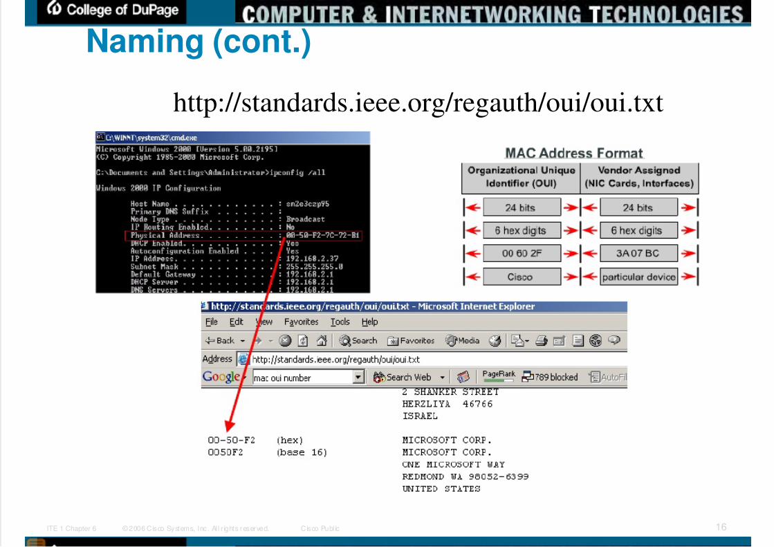
Naming (cont.)
http://standards.ieee.org/regauth/oui/oui.txt

5/9/2018 Exp3 LAN Switching Ch02-TonyChen - slidepdf.com
http://slidepdf.com/reader/full/exp3-lan-switching-ch02-tonychen 17/89 © 2006 Cisco Systems, Inc. Al l r ights reserved. Cisco Publ icITE 1 Chapter 6 17
MAC Address: I/G bit and U/L bit The first 2 bits of a MAC address are used as I/G bit
and U/L bit.
I/G bit and U/L bit The first two bits of a destination address convey
certain information: – I/G = 0
•Individual address: the destination is a singenode.
– I/G = 1
•Group address: the destination is a group of LANnodes (multicast or broadcast address).
– U/L = 0
•Universally administered address: the adapteruses its burned-in MAC address.
– U/L = 1
•Locally administered address: the adapter uses alogical address (assigned by networkadministrator). U/L=1 may result in a hex code of0x02 in the first byte. The U/L bit is always setwhen a logical address is assigned (even if theassigned address doesn't follow this convention).Therefore, it is impossible to imitate a burned-inaddress; but other logical address may be imitatedat any time.
Source addresses don't use the I/G bit (becausemultiple stations cannot be the source of a singleframe). The first bit of a source address doesn'thave any special meaning in Ethernet LANs; inToken-Ring LANs, it is used as RII bit (RII = routinginformation indicator). The RII bit indicates that
source routing information will follow the sourceaddress.
http://www.synapse.de/ban/HTML/P_LAYE
R2/Eng/P_lay207.html
http://en.wikipedia.org/wiki/MAC_address
5/9/2018 Exp3 LAN Switching Ch02-TonyChen - slidepdf.com
http://slidepdf.com/reader/full/exp3-lan-switching-ch02-tonychen 18/89 © 2006 Cisco Systems, Inc. Al l r ights reserved. Cisco Publ icITE 1 Chapter 6 18
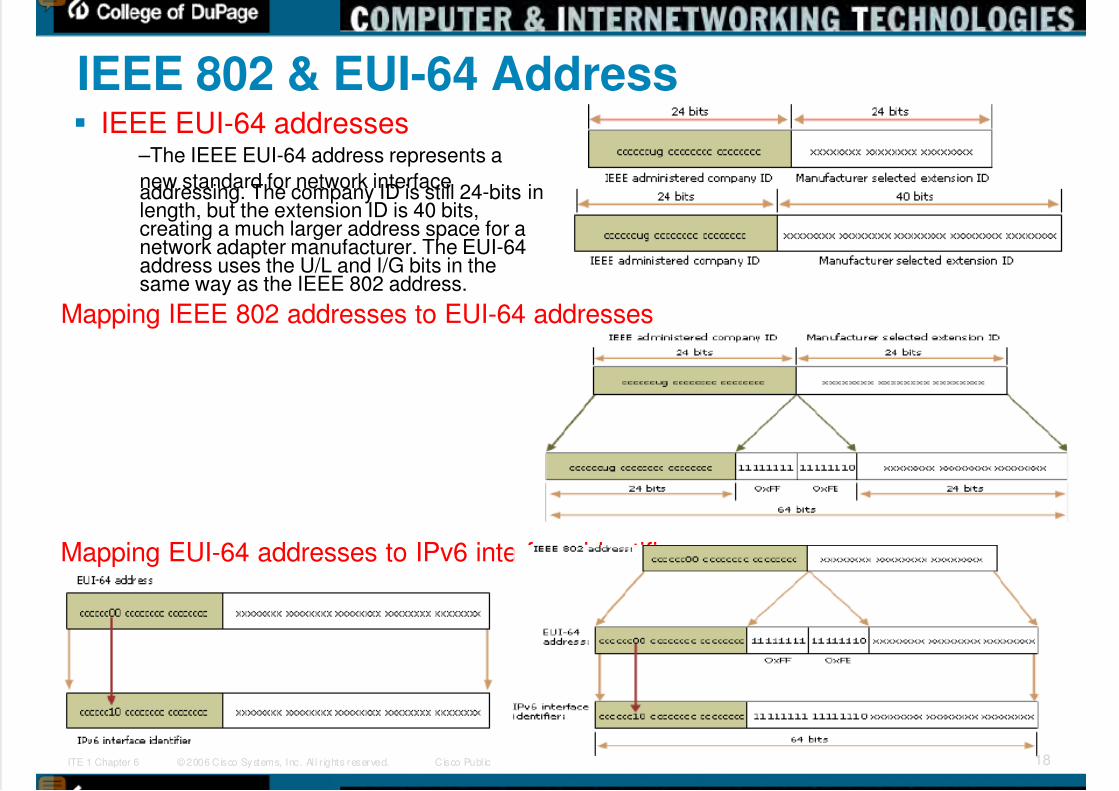
IEEE 802 & EUI-64 Address IEEE EUI-64 addresses
–The IEEE EUI-64 address represents a
new standard for network interfaceaddressing. The company ID is still 24-bits inlength, but the extension ID is 40 bits,creating a much larger address space for anetwork adapter manufacturer. The EUI-64address uses the U/L and I/G bits in thesame way as the IEEE 802 address.
Mapping IEEE 802 addresses to EUI-64 addresses
Mapping EUI-64 addresses to IPv6 interface identifiers

5/9/2018 Exp3 LAN Switching Ch02-TonyChen - slidepdf.com
http://slidepdf.com/reader/full/exp3-lan-switching-ch02-tonychen 19/89 © 2006 Cisco Systems, Inc. Al l r ights reserved. Cisco Publ icITE 1 Chapter 6 19
Duplex Settings There are 2 types of duplex settings used on an Ethernet:
Half Duplex:
–Half-duplex relies on unidirectional data flow where sending andreceiving data are not performed at the same time.•This is similar to how walkie-talkies function in that only one personcan talk at any one time.
•efficiency is typically at 50 to 60 percent of the 10-Mb/s bandwidth
–Half-duplex uses CSMA/CD to help reduce the collisions.
–Half-duplex are typically in older hardware, such as hubs.
•Nodes that are attached to hubs that share their connection to aswitch port must operate in half-duplex mode.
–Nodes can operate in a half-duplex mode if the NIC card cannotbe configured for full duplex operations.
•In this case the port on the switch defaults to a half-duplex as well.
Full Duplex: –In full-duplex communication, data flow is bidirectional, so data
can be sent and received at the same time.•Most Ethernet, Fast Ethernet, and Gigabit Ethernet NICs sold todayoffer full-duplex capability.
–In full-duplex mode, the collision detect circuit is disabled.•Frames sent by the two connected end nodes cannot collide becausethe end nodes use two separate circuits in the cable.
–Each full-duplex connection uses only one port.
•Full-duplex connections require a switch that supports full duplex or adirect connection between two nodes that each support full duplex.

5/9/2018 Exp3 LAN Switching Ch02-TonyChen - slidepdf.com
http://slidepdf.com/reader/full/exp3-lan-switching-ch02-tonychen 20/89 © 2006 Cisco Systems, Inc. Al l r ights reserved. Cisco Publ icITE 1 Chapter 6 20
Switch Port Settings A port on a switch needs to be configured with duplex
settings that match the media type.
The Cisco Catalyst switches have three settings –The auto option sets autonegotiation of duplex mode. Withautonegotiation enabled, the two ports communicate to decide the bestmode of operation
–The full option sets full-duplex mode.
–The half option sets half-duplex mode.
For Fast Ethernet and 10/100/1000 ports, the default is auto.
For 100BASE-FX ports, the default is full.
The 10/100/1000 ports operate in either half- or full-duplexmode when they are set to 10 or 100 Mb/s, but when set to1,000 Mb/s, they operate only in full-duplex mode
Note: Autonegotiation can produce unpredictable results.
–By default, when autonegotiation fails, the Catalyst switch setsthe corresponding switch port to half-duplex mode.•This type of failure happens when an attached device does notsupport autonegotiation.
–If the device is manually configured having half-duplex on oneend and full-duplex on the other causes late collision errors atthe half-duplex end.
•To avoid this situation, manually set the duplex parameters of the
switch to match the attached device.

5/9/2018 Exp3 LAN Switching Ch02-TonyChen - slidepdf.com
http://slidepdf.com/reader/full/exp3-lan-switching-ch02-tonychen 21/89 © 2006 Cisco Systems, Inc. Al l r ights reserved. Cisco Publ icITE 1 Chapter 6 21
Switch Port Settings: auto-MDIX auto-MDIX
–You used to be required to use certain cabletypes (cross-over, straight-through) whenconnecting between specific devices, switch-to-switch or switch-to-router.
–Instead, you can now use the mdix autointerface configuration command in the CLI toenable the automatic medium-dependentinterface crossover (auto-MDIX) feature
•When the auto-MDIX feature is enabled, theswitch detects the required cable type forcopper Ethernet connections and configures theinterfaces accordingly.
•Therefore, you can use either a crossover or astraight-through cable for connections to acopper 10/100/1000 port on the switch,regardless of the type of device on the otherend of the connection.
–The auto-MDIX feature is enabled by defaulton switches running Cisco IOS Release12.2(18)SE or later. For releases betweenCisco IOS Release 12.1(14)EA1 and12.2(18)SE, the auto-MDIX feature isdisabled by default.
Switch# configure terminalSwitch(config)# interface gigabitethernet0/1Switch(config-if)# speed autoSwitch(config-if)# duplex autoSwitch(config-if)# mdix auto
Switch(config-if)# end
Table 10-3 Link Conditions and Auto-MDIX Settings
Local Side
Auto-MDIX
Remote Side
Auto-MDIX
With Correct
Cabling
WithIncorrect
CablingOn On Link up Link up
On Off Link up Link up
Off On Link up Link up
Off Off Link up Link down
http://www.cisco.com/en/US/docs/switches/lan/catalyst3560/software/release/12.2_25_see/configuration/guide/swint.html#wp1193977
“correct cabling” means a cross-overcable and “incorrect cabling” means astraight-through cable

5/9/2018 Exp3 LAN Switching Ch02-TonyChen - slidepdf.com
http://slidepdf.com/reader/full/exp3-lan-switching-ch02-tonychen 22/89 © 2006 Cisco Systems, Inc. Al l r ights reserved. Cisco Publ icITE 1 Chapter 6 22
MAC Address Tables MAC Addressing and Switch MAC Address Tables
–Switches use MAC addresses to direct network communications tothe appropriate port toward the destination node.For a switch to know which port to use to transmit a unicast frame, itmust first learn which nodes exist on each of its ports.
A switch determines how to handle incoming data frames by using itsMAC address table.
A switch builds its MAC address table by recording the MAC addressesof the nodes connected to each of its ports.
Once a MAC address for a specific node on a specific port is recorded inthe address table, the switch then knows to send traffic destined for thatspecific node out the port.
When an incoming data frame is received by a switch and thedestination MAC address is not in the table, the switch forwards the frame
out all ports, except for the port on which it was received.When the destination node responds, the switch records the node's MACaddress in the address table from the frame's source address field.
In networks with multiple interconnected switches, the MAC addresstables record multiple MAC addresses for the ports connecting theswitches which reflect the node's beyond.
Typically, switch ports used to interconnect two switches have multipleMAC addresses recorded in the MAC address table.
5/9/2018 Exp3 LAN Switching Ch02-TonyChen - slidepdf.com
http://slidepdf.com/reader/full/exp3-lan-switching-ch02-tonychen 23/89 © 2006 Cisco Systems, Inc. Al l r ights reserved. Cisco Publ icITE 1 Chapter 6 23
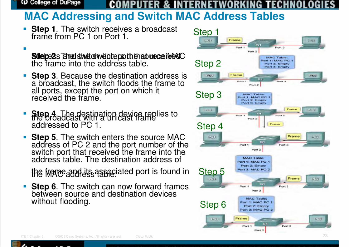
MAC Addressing and Switch MAC Address Tables Step 1. The switch receives a broadcast
frame from PC 1 on Port 1.
Step 2. The switch enters the source MACaddress and the switch port that receivedthe frame into the address table.
Step 3. Because the destination address isa broadcast, the switch floods the frame toall ports, except the port on which itreceived the frame.
Step 4. The destination device replies tothe broadcast with a unicast frameaddressed to PC 1.
Step 5. The switch enters the source MACaddress of PC 2 and the port number of theswitch port that received the frame into theaddress table. The destination address of
the frame and its associated port is found inthe MAC address table.
Step 6. The switch can now forward framesbetween source and destination deviceswithout flooding.
Step 1
Step 2
Step 3
Step 4
Step 5
Step 6

5/9/2018 Exp3 LAN Switching Ch02-TonyChen - slidepdf.com
http://slidepdf.com/reader/full/exp3-lan-switching-ch02-tonychen 24/89 © 2006 Cisco Systems, Inc. Al l r ights reserved. Cisco Publ icITE 1 Chapter 6 24
Bandwidth and Throuhgput A major disadvantage of Ethernet is collisions.
–Collisions occur when two hosts transmit framessimultaneously.
–When a collision occurs, the transmitted frames are corruptedor destroyed.
–The sending hosts stop sending further transmissions for arandom period, based on the Ethernet 802.3 rules of CSMA/CD
It is important to understand that when stating thebandwidth of the Ethernet network is 10 Mb/s, fullbandwidth for transmission is available only after anycollisions have been resolved.
–A hub offers no mechanisms to either eliminate or reducecollisions and the available bandwidth that any one node has totransmit is correspondingly reduced.
–As a result, the number of nodes sharing the Ethernet networkwill have effect on the throughput
5/9/2018 Exp3 LAN Switching Ch02-TonyChen - slidepdf.com
http://slidepdf.com/reader/full/exp3-lan-switching-ch02-tonychen 25/89 © 2006 Cisco Systems, Inc. Al l r ights reserved. Cisco Publ icITE 1 Chapter 6 25
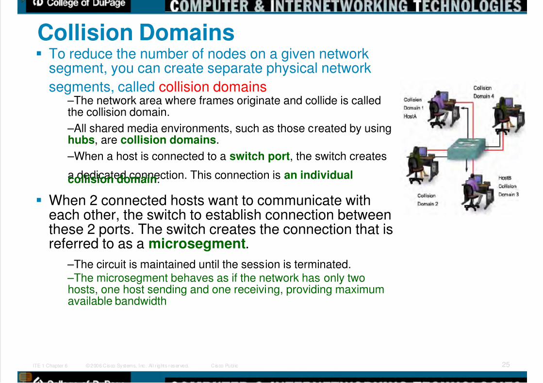
Collision Domains To reduce the number of nodes on a given network
segment, you can create separate physical network
segments, called collision domains –The network area where frames originate and collide is calledthe collision domain.
–All shared media environments, such as those created by usinghubs, are collision domains.
–When a host is connected to a switch port, the switch creates
a dedicated connection. This connection is an individualcollision domain.
When 2 connected hosts want to communicate witheach other, the switch to establish connection betweenthese 2 ports. The switch creates the connection that isreferred to as a microsegment.
–The circuit is maintained until the session is terminated. –The microsegment behaves as if the network has only twohosts, one host sending and one receiving, providing maximumavailable bandwidth
5/9/2018 Exp3 LAN Switching Ch02-TonyChen - slidepdf.com
http://slidepdf.com/reader/full/exp3-lan-switching-ch02-tonychen 26/89 © 2006 Cisco Systems, Inc. Al l r ights reserved. Cisco Publ icITE 1 Chapter 6 26
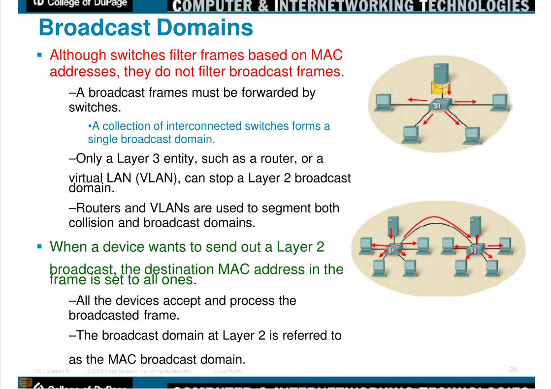
Broadcast Domains Although switches filter frames based on MAC
addresses, they do not filter broadcast frames.
–A broadcast frames must be forwarded byswitches.
•A collection of interconnected switches forms asingle broadcast domain.
–Only a Layer 3 entity, such as a router, or a
virtual LAN (VLAN), can stop a Layer 2 broadcastdomain.
–Routers and VLANs are used to segment bothcollision and broadcast domains.
When a device wants to send out a Layer 2
broadcast, the destination MAC address in theframe is set to all ones.
–All the devices accept and process thebroadcasted frame.
–The broadcast domain at Layer 2 is referred to
as the MAC broadcast domain.

5/9/2018 Exp3 LAN Switching Ch02-TonyChen - slidepdf.com
http://slidepdf.com/reader/full/exp3-lan-switching-ch02-tonychen 27/89
© 2006 Cisco Systems, Inc. Al l r ights reserved. Cisco Publ icITE 1 Chapter 6 27
Network Latency Latency is the time a frame or a packet takes to
travel from the source to the final destination.
–Users of network-based applications experiencelatency when they have to wait many minutes toaccess data stored in a data center.
Latency has at least 3 sources.
–First, the time it takes the source NIC to placevoltage pulses on the wire, and the time it takesthe destination NIC to interpret these pulses.
•This is sometimes called NIC delay, typicallyaround 1 microsecond for a 10BASE-T NIC.
–Second, the actual propagation delay as the
signal takes time to travel through the cable.•Longer cable and slower nominal velocity ofpropagation (NVP) result in more propagation delay.
–Third, latency is added based on networkdevices that are in the path between two devices.
•These are either Layer 1, Layer 2, or Layer 3
devices.
5/9/2018 Exp3 LAN Switching Ch02-TonyChen - slidepdf.com
http://slidepdf.com/reader/full/exp3-lan-switching-ch02-tonychen 28/89
© 2006 Cisco Systems, Inc. Al l r ights reserved. Cisco Publ icITE 1 Chapter 6 28
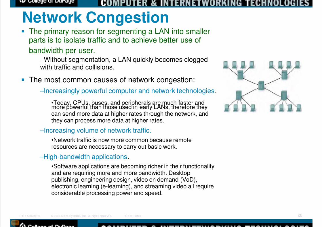
Network Congestion The primary reason for segmenting a LAN into smaller
parts is to isolate traffic and to achieve better use of
bandwidth per user. –Without segmentation, a LAN quickly becomes cloggedwith traffic and collisions.
The most common causes of network congestion:
–Increasingly powerful computer and network technologies.
•Today, CPUs, buses, and peripherals are much faster andmore powerful than those used in early LANs, therefore theycan send more data at higher rates through the network, andthey can process more data at higher rates.
–Increasing volume of network traffic.
•Network traffic is now more common because remoteresources are necessary to carry out basic work.
–High-bandwidth applications.
•Software applications are becoming richer in their functionalityand are requiring more and more bandwidth. Desktoppublishing, engineering design, video on demand (VoD),electronic learning (e-learning), and streaming video all requireconsiderable processing power and speed.

5/9/2018 Exp3 LAN Switching Ch02-TonyChen - slidepdf.com
http://slidepdf.com/reader/full/exp3-lan-switching-ch02-tonychen 29/89
© 2006 Cisco Systems, Inc. Al l r ights reserved. Cisco Publ icITE 1 Chapter 6 29
LAN Segmentation LANs are segmented into a number of
smaller collision and broadcast domainsusing routers and switches.
Bridges and Switches
–Bridges and switches share many attributes, severaldistinctions differentiate these technologies.
•Bridges are generally used to segment a LAN into acouple of smaller segments.
•Switches are generally used to segment a large LANinto many smaller segments.
•Bridges have only a few ports for LAN connectivity
•Switches have many ports.
Routers –Because routers do not forward broadcast traffic bydefault, they can be used to create broadcastdomains.
•Each router interface connects to a separate network,containing broadcast traffic within the LAN segment inwhich it originated.

5/9/2018 Exp3 LAN Switching Ch02-TonyChen - slidepdf.com
http://slidepdf.com/reader/full/exp3-lan-switching-ch02-tonychen 30/89
© 2006 Cisco Systems, Inc. Al l r ights reserved. Cisco Publ icITE 1 Chapter 6 30
LAN Design Consideration Controlling Network Latency
–SWITCHES can introduce latency on a network whenoversubscribed on a busy network.
•For example, if a core level switch has to support 48 ports, each onecapable of running at 1000 Mb/s full duplex, the switch should supportaround 96 Gb/s internal throughput if it is to maintain full wirespeed acrossall ports simultaneously.
–The use of ROUTERS increase latency on a network.
•When a Layer 3 device, such as a router, needs to examine the Layer 3addressing information contained within the frame, it must read further intothe frame than a Layer 2 device, which creates a longer processing time.
•However, appropriate use of Layer 3 devices helps prevent contentionfrom broadcast traffic in a large broadcast domain.

5/9/2018 Exp3 LAN Switching Ch02-TonyChen - slidepdf.com
http://slidepdf.com/reader/full/exp3-lan-switching-ch02-tonychen 31/89
© 2006 Cisco Systems, Inc. Al l r ights reserved. Cisco Publ icITE 1 Chapter 6 31
LAN Design Consideration Removing Bottlenecks
–Bottlenecks on a network are places where highnetwork congestion results in slow performance.
•In this figure which shows six computers and a singleserver are connected to the same switch.
–Each workstation and the server are all connected using a100 Mb/s NIC.
–If each connection was used at full capacity, each
computer would be able to use only 16.7 Mb/s, one-sixth ofthe 100 Mb/s bandwidth.
•To reduce the bottleneck to the server, additionalnetwork cards can be installed, which increases thetotal bandwidth the server is capable of receiving.
–Higher capacity links (for example, upgrading from
100 Mb/s to 1000 Mb/s connections) and usingmultiple links leveraging link aggregationtechnologies (for example, combining two links as ifthey were one to double a connection's capacity)can help to reduce the bottlenecks created by inter-switch links and router links.

5/9/2018 Exp3 LAN Switching Ch02-TonyChen - slidepdf.com
http://slidepdf.com/reader/full/exp3-lan-switching-ch02-tonychen 32/89
© 2006 Cisco Systems, Inc. Al l r ights reserved. Cisco Publ icITE 1 Chapter 6 32
Activity: Identify all the collision domain and broadcast domain

5/9/2018 Exp3 LAN Switching Ch02-TonyChen - slidepdf.com
http://slidepdf.com/reader/full/exp3-lan-switching-ch02-tonychen 33/89
© 2006 Cisco Systems, Inc. Al l r ights reserved. Cisco Publ icITE 1 Chapter 6 33
Switch Forwarding Methods Switches used one of the following forwarding methods for
switching data between network ports: store-and-forward or
cut-through switching. – However, store-and-forward is the sole forwarding methodused on current models of Cisco Catalyst switches.
Store-and-Forward Switching –In store-and-forward switching, when the switch receives theframe, it stores the data in buffers until the complete frame hasbeen received.
•During the storage process, the switch performs an error check usingCRC trailer.
•After confirming the integrity of the frame, the frame is forwarded out theappropriate port
•When an error is detected in a frame, the switch discards the frame.
–Store-and-forward switching is required for QoS analysis onconverged networks where frame classification for trafficprioritization is necessary.
Cut-through Switching
–In cut-through switching, the switch acts upon the data as soon asit read the destination MAC address so that it can determine whichport to forward the data.
•The destination MAC address is located in the first 6 bytes of the frame.
–The switch does not perform any error checking on the frame.
–Cut-through switching is faster than store-and-forward switching.•However, because the switch does not perform any error checking, itforwards corrupt frames throughout the network.
•The corrupt frames consume bandwidth while they are being forwarded.
5/9/2018 Exp3 LAN Switching Ch02-TonyChen - slidepdf.com
http://slidepdf.com/reader/full/exp3-lan-switching-ch02-tonychen 34/89
© 2006 Cisco Systems, Inc. Al l r ights reserved. Cisco Publ icITE 1 Chapter 6 34
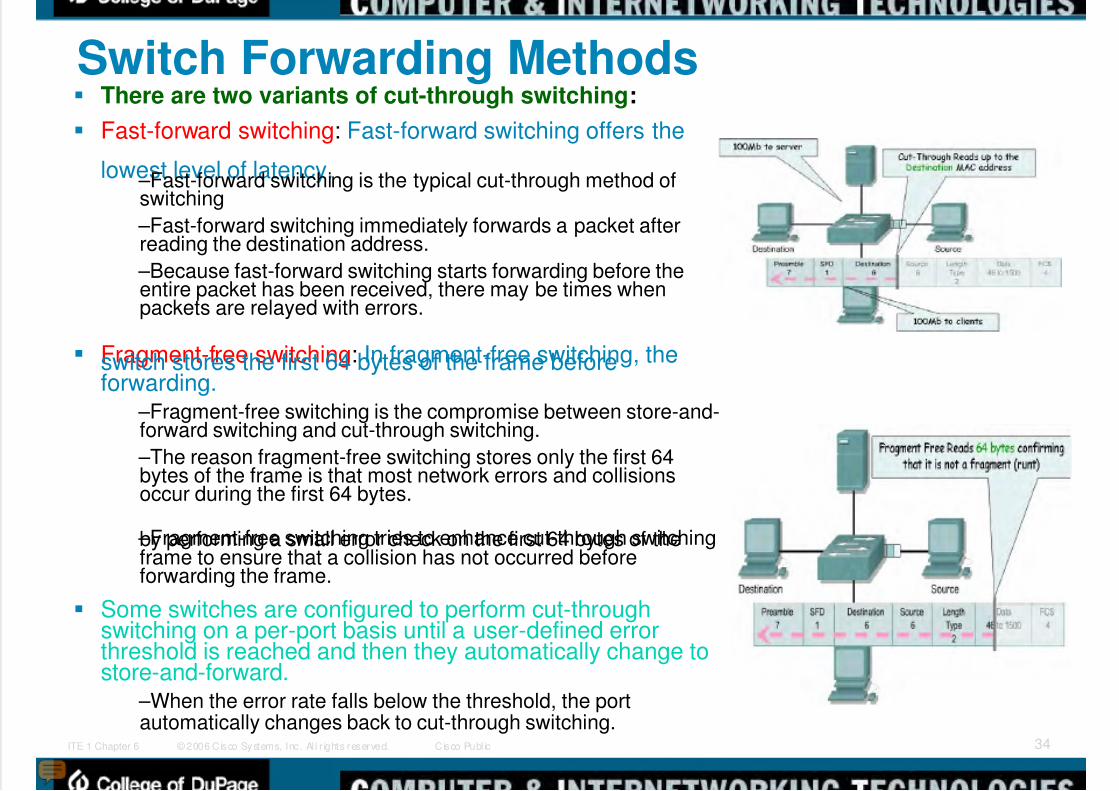
Switch Forwarding Methods There are two variants of cut-through switching:
Fast-forward switching: Fast-forward switching offers the
lowest level of latency. –Fast-forward switching is the typical cut-through method ofswitching
–Fast-forward switching immediately forwards a packet afterreading the destination address.
–Because fast-forward switching starts forwarding before theentire packet has been received, there may be times whenpackets are relayed with errors.
Fragment-free switching: In fragment-free switching, theswitch stores the first 64 bytes of the frame beforeforwarding.
–Fragment-free switching is the compromise between store-and-forward switching and cut-through switching.
–The reason fragment-free switching stores only the first 64bytes of the frame is that most network errors and collisionsoccur during the first 64 bytes.
–Fragment-free switching tries to enhance cut-through switchingby performing a small error check on the first 64 bytes of theframe to ensure that a collision has not occurred beforeforwarding the frame.
Some switches are configured to perform cut-throughswitching on a per-port basis until a user-defined errorthreshold is reached and then they automatically change tostore-and-forward.
–When the error rate falls below the threshold, the portautomatically changes back to cut-through switching.

5/9/2018 Exp3 LAN Switching Ch02-TonyChen - slidepdf.com
http://slidepdf.com/reader/full/exp3-lan-switching-ch02-tonychen 35/89
© 2006 Cisco Systems, Inc. Al l r ights reserved. Cisco Publ icITE 1 Chapter 6 35
Symmetric and Asymmetric Switching LAN switching may be classified as symmetric or asymmetric
based on the way bandwidth is allocated to the switch ports.
Asymmetric –Asymmetric LAN switch provides switched connectionsbetween ports of unlike bandwidth, such as a combinationof 10 Mb/s, 100 Mb/s, and 1000 Mb/s ports.
•Asymmetric switching enables more bandwidth to bededicated to a server switch port to prevent a bottleneck.
–This allows smoother traffic flows where multiple clientsare communicating with a server at the same time.
•Memory buffering is required on an asymmetric switch.
–For the switch to match the different data rates ondifferent ports, entire frames are kept in the memory bufferand are moved to the port one after the other as required.
Symmetric –Symmetric switching provides switched connectionsbetween ports with the same bandwidth, such as all 100Mb/s ports or all 1000 Mb/s ports. –Symmetric switching is optimized for a distributed trafficload, such as in a peer-to-peer environment.
Most current switches are asymmetric switchesbecause this type of switch offers the greatest flexibility.

5/9/2018 Exp3 LAN Switching Ch02-TonyChen - slidepdf.com
http://slidepdf.com/reader/full/exp3-lan-switching-ch02-tonychen 36/89
© 2006 Cisco Systems, Inc. Al l r ights reserved. Cisco Publ icITE 1 Chapter 6 36
Memory Buffering Memory Buffering
–An Ethernet switch may use a buffering technique to store frames
before forwarding them. –Buffering may also be used when the port is busy due to congestionand switch stores the frame until it can be transmitted.
–Memory buffering is built into the hardware of the switch and, it is notconfigurable.
There are two methods of memory buffering
–Port-based Memory Buffering
•In port-based memory buffering, frames are stored in queues thatare linked to specific incoming ports.
•A frame is transmitted to the outgoing port only when all the framesahead of it in the queue have been successfully transmitted.
–Shared Memory Buffering
•Shared memory buffering deposits all frames into a commonmemory buffer that all the ports on the switch share.
•The amount of memory required by a port is dynamically allocated.
•This allows the packet to be received on one port and thentransmitted on another port, without moving it to a different queue.
•This is important to asymmetric switching, where frames are beingexchanged between different rate ports.

5/9/2018 Exp3 LAN Switching Ch02-TonyChen - slidepdf.com
http://slidepdf.com/reader/full/exp3-lan-switching-ch02-tonychen 37/89
© 2006 Cisco Systems, Inc. Al l r ights reserved. Cisco Publ icITE 1 Chapter 6 37
Layer 2 and Layer 3 Switching Layer 2 LAN switching
–A Layer 2 LAN switch performs switching andfiltering based only on the OSI data link layer(Layer 2) MAC address.
•A Layer 2 switch is completely transparent tonetwork protocols and user applications.
•A Layer 2 switch builds a MAC address table that
it uses to make forwarding decisions.
Layer 3 LAN switching
–A Layer 3 switch can also use IP addressinformation. Instead of only learning which MACaddresses are associated with each of its ports.
•Layer 3 switches are also capable of performingLayer 3 routing functions, reducing the need fordedicated routers on a LAN.
•Because Layer 3 switches have specializedswitching hardware, they can typically route dataas quickly as they can switch.

5/9/2018 Exp3 LAN Switching Ch02-TonyChen - slidepdf.com
http://slidepdf.com/reader/full/exp3-lan-switching-ch02-tonychen 38/89
© 2006 Cisco Systems, Inc. Al l r ights reserved. Cisco Publ icITE 1 Chapter 6 38
Layer 3 Switch and Router Comparison However, Layer 3 switches do not
completely replace the need forrouters on a network.
–Routers perform additional Layer 3services that Layer 3 switches are notcapable of performing.
–Dedicated routers are more flexible intheir support of WAN interface cards(WIC), making them the preferred, andsometimes only, choice for connecting to aWAN.
–Layer 3 switches can provide basicrouting functions in a LAN and reduce theneed for dedicated routers.

5/9/2018 Exp3 LAN Switching Ch02-TonyChen - slidepdf.com
http://slidepdf.com/reader/full/exp3-lan-switching-ch02-tonychen 39/89
© 2006 Cisco Systems, Inc. Al l r ights reserved. Cisco Publ icITE 1 Chapter 6 39
Layer 3 switching: Layer 3 Switching Demystified
In discussions about Layer 3 switches,often the prime area of focus is rawperformance which refers to theaggregate number of packets that adevice can switch in and out over afixed period of time.
–Layer 3 switches tend to have packetswitching throughputs in the millions ofpackets per second (pps), while
traditional general-purpose routers haveevolved from the 100,000 pps range toover a million pps.
–In general-purpose routers, packetswitching takes place usingmicroprocessor-based engines, whereasa Layer 3 switch performs this using
application specific integrated circuit(ASIC) hardware.
–In essence, aggregate performance isthe primary difference between Layer 3switches and traditional routers.
http://www.cisco.com/warp/public/cc/so/neso/lnso/cpso/l3c85_wp.htm

5/9/2018 Exp3 LAN Switching Ch02-TonyChen - slidepdf.com
http://slidepdf.com/reader/full/exp3-lan-switching-ch02-tonychen 40/89
© 2006 Cisco Systems, Inc. Al l r ights reserved. Cisco Publ icITE 1 Chapter 6 40
Layer 4 - 7 switching Layer 4 – 7 switching
–The Cisco Content SwitchingModule (CSM) adds advancedlayer 4 to layer 7 contentswitching capabilities to theCisco Catalyst 6500 Series
Switch or the Cisco 7600Series Router providing high-performance, feature richlayer 4 to layer 7 load
balancing to existing layer 2and layer 3 features of theCatalyst platforms
http://www.cisco.com/en/US/products/hw/modules/ps2706/ps780/

5/9/2018 Exp3 LAN Switching Ch02-TonyChen - slidepdf.com
http://slidepdf.com/reader/full/exp3-lan-switching-ch02-tonychen 41/89
© 2006 Cisco Systems, Inc. Al l r ights reserved. Cisco Publ icITE 1 Chapter 6 41
The Command Line Interface (CLI) Modes As a security feature, Cisco IOS separated the
EXEC sessions into these access levels:
–User EXEC: Allows a person to access only alimited number of basic monitoring commands.•User EXEC mode is identified by the > prompt.
•To change from user EXEC mode to privileged EXECmode, enter the enable command.
–Privileged EXEC: Allows a person to access alldevice commands, such as those used forconfiguration and management.
•Privileged EXEC mode is identified by the # prompt.•To change from privileged EXEC mode to user EXECmode, enter the disable command.
Once you have entered privileged EXEC mode,you can access other configuration modes.
–Global Configuration Mode•To configure global switch parameters such as the
switch hostname or the switch IP address.•To access global configuration mode, enter configureterminal command. The prompt changes to (config)#.
–Interface Configuration Mode•To access interface configuration mode enter theinterface<interface name> command.
•The prompt changes to (config-if)#.
•To exit configuration mode, enter the exit command.

5/9/2018 Exp3 LAN Switching Ch02-TonyChen - slidepdf.com
http://slidepdf.com/reader/full/exp3-lan-switching-ch02-tonychen 42/89
© 2006 Cisco Systems, Inc. Al l r ights reserved. Cisco Publ icITE 1 Chapter 6 42
GUI-based Alternatives to the CLI There are a number of graphical management alternatives for
managing a Cisco switch.
Cisco Network Assistant –Cisco Network Assistant is a PC-based GUI network managementapplication. You can configure and manage groups of switches orstandalone switches. Cisco Network Assistant is available at no cost andcan be downloaded from Cisco (CCO username/password required):
–http://www.cisco.com/go/networkassistant .
CiscoView Application
–The CiscoView device-management application displays a physical viewof the switch that you can use to set configuration parameters.
–The CiscoView application, purchased separately, can be a standaloneapplication or part of a SNMP platform.
–http://www.cisco.com/en/US/products/sw/cscowork/ps4565/prod_bulletin0900aecd802948b0.html
Cisco Device Manager
–Cisco Device Manager is web-based software that is stored in the switch
memory. –You can access Device Manager from anywhere in your network througha web browser.
SNMP Network Management
–You can manage switches from a SNMP-compatible managementstation, such as HP OpenView. SNMP network management is morecommon in large enterprise networks.
–http://h20229.www2.hp.com/news/about/index.html.
5/9/2018 Exp3 LAN Switching Ch02-TonyChen - slidepdf.com
http://slidepdf.com/reader/full/exp3-lan-switching-ch02-tonychen 43/89
© 2006 Cisco Systems, Inc. Al l r ights reserved. Cisco Publ icITE 1 Chapter 6 43
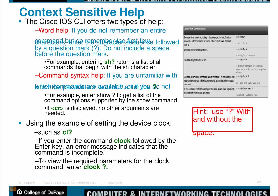
Context Sensitive Help The Cisco IOS CLI offers two types of help:
–Word help: If you do not remember an entire
command but do remember the first fewcharacters, enter the character sequence followedby a question mark (?). Do not include a spacebefore the question mark.
•For example, entering sh? returns a list of allcommands that begin with the sh character.
–Command syntax help: If you are unfamiliar with
which commands are available, or if you do notknow the parameters required, enter the ?.•For example, enter show ? to get a list of thecommand options supported by the show command.
•If <cr> is displayed, no other arguments areneeded.
Using the example of setting the device clock.
–such as cl?.
–If you enter the command clock followed by theEnter key, an error message indicates that thecommand is incomplete.
–To view the required parameters for the clockcommand, enter clock ?.
Hint: use “?” Withand without the
space.

5/9/2018 Exp3 LAN Switching Ch02-TonyChen - slidepdf.com
http://slidepdf.com/reader/full/exp3-lan-switching-ch02-tonychen 44/89
© 2006 Cisco Systems, Inc. Al l r ights reserved. Cisco Publ icITE 1 Chapter 6 44
Console Error MessagesConsole error messages
help identify problemswhen an incorrectcommand has beenentered.
–Ambiguous command• not enough characters tomake it a unique command
–Incomplete command
• have not finish the whole
command syntax
–Incorrect command
• position of command whichis not correct “^”.

5/9/2018 Exp3 LAN Switching Ch02-TonyChen - slidepdf.com
http://slidepdf.com/reader/full/exp3-lan-switching-ch02-tonychen 45/89
© 2006 Cisco Systems, Inc. Al l r ights reserved. Cisco Publ icITE 1 Chapter 6 45
The Command History Buffer The Cisco CLI provides a history or record of
commands that have been entered.
–This feature, called command history, is particularlyuseful in helping recall long commands.
With the command history feature, you cancomplete the following tasks:
–Display the contents of the command buffer.
–Set the command history buffer size.
–Recall previously entered commands stored in thehistory buffer.
•There is a buffer for each configuration mode.
The system records the last 10 command lines inits buffer by default.
–You can use the show history command to viewrecently entered EXEC commands.
–The command history can be disabled by using theterminal no history command.
–To revert the terminal history size back to its defaultvalue of 10 lines, enter the terminal no history sizecommand in privileged EXEC mode.
5/9/2018 Exp3 LAN Switching Ch02-TonyChen - slidepdf.com
http://slidepdf.com/reader/full/exp3-lan-switching-ch02-tonychen 46/89
© 2006 Cisco Systems, Inc. Al l r ights reserved. Cisco Publ icITE 1 Chapter 6 46
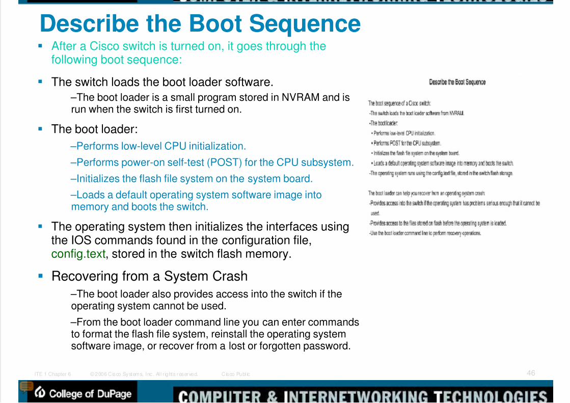
Describe the Boot Sequence After a Cisco switch is turned on, it goes through the
following boot sequence:
The switch loads the boot loader software.
–The boot loader is a small program stored in NVRAM and isrun when the switch is first turned on.
The boot loader:
–Performs low-level CPU initialization.
–Performs power-on self-test (POST) for the CPU subsystem.
–Initializes the flash file system on the system board.
–Loads a default operating system software image intomemory and boots the switch.
The operating system then initializes the interfaces usingthe IOS commands found in the configuration file,config.text, stored in the switch flash memory.
Recovering from a System Crash
–The boot loader also provides access into the switch if theoperating system cannot be used.
–From the boot loader command line you can enter commandsto format the flash file system, reinstall the operating systemsoftware image, or recover from a lost or forgotten password.

5/9/2018 Exp3 LAN Switching Ch02-TonyChen - slidepdf.com
http://slidepdf.com/reader/full/exp3-lan-switching-ch02-tonychen 47/89
© 2006 Cisco Systems, Inc. Al l r ights reserved. Cisco Publ icITE 1 Chapter 6 47
Prepare to Configure the Switch The initial startup of a Catalyst switch requires the
completion of the following steps:
Step 1. Before starting the switch, verify thefollowing:
–All network cable connections are secure.
–Your PC is connected to the console port.
–Your terminal emulator application, such as
HyperTerminal, is running and configured correctly.
Step 2. Attach the power cable plug to the switchpower supply socket.
–Some Catalyst switches, including the CiscoCatalyst 2960 series, do not have power buttons.
Step 3. Observe the boot sequence as follows:
–When the switch is on, the POST begins.
–During POST, the LEDs blink while a series of testsdetermine that the switch is functioning properly.
–If the switch fails POST, the SYST LED turnsamber.

5/9/2018 Exp3 LAN Switching Ch02-TonyChen - slidepdf.com
http://slidepdf.com/reader/full/exp3-lan-switching-ch02-tonychen 48/89
© 2006 Cisco Systems, Inc. Al l r ights reserved. Cisco Publ icITE 1 Chapter 6 48
Configure Management Interface To manage a switch remotely using TCP/IP, you need to
assign the switch an IP address.
–An access layer switch is much like a PC in that you need toconfigure an IP address, a subnet mask, and a default gateway.
–This IP address is assigned to a virtual interface called a VLAN
–It is necessary to ensure the VLAN is assigned to a specific portor ports on the switch.
–The default configuration on the switch is to have themanagement of the switch controlled through VLAN 1. However, a
best practice for basic switch configuration is to change themanagement VLAN to a VLAN other than VLAN 1.
Note that a Layer 2 switch, such as the Cisco Catalyst 2960,only permits a single VLAN interface to be active at a time.
–This means that the Layer 3 interface, interface VLAN 99, isactive, but the Layer 3 interface, interface VLAN 1, is not active.
5/9/2018 Exp3 LAN Switching Ch02-TonyChen - slidepdf.com
http://slidepdf.com/reader/full/exp3-lan-switching-ch02-tonychen 49/89
© 2006 Cisco Systems, Inc. Al l r ights reserved. Cisco Publ icITE 1 Chapter 6 49
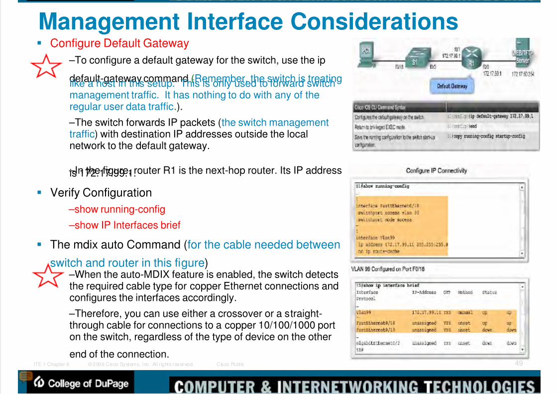
Management Interface Considerations Configure Default Gateway
–To configure a default gateway for the switch, use the ip
default-gateway command (Remember, the switch is treatinglike a host in this setup. This is only used to forward switchmanagement traffic. It has nothing to do with any of theregular user data traffic.).
–The switch forwards IP packets (the switch managementtraffic) with destination IP addresses outside the localnetwork to the default gateway.
–In the figure, router R1 is the next-hop router. Its IP addressis 172.17.99.1.
Verify Configuration
–show running-config
–show IP Interfaces brief
The mdix auto Command (for the cable needed between
switch and router in this figure) –When the auto-MDIX feature is enabled, the switch detectsthe required cable type for copper Ethernet connections andconfigures the interfaces accordingly.
–Therefore, you can use either a crossover or a straight-through cable for connections to a copper 10/100/1000 porton the switch, regardless of the type of device on the other
end of the connection.
5/9/2018 Exp3 LAN Switching Ch02-TonyChen - slidepdf.com
http://slidepdf.com/reader/full/exp3-lan-switching-ch02-tonychen 50/89
© 2006 Cisco Systems, Inc. Al l r ights reserved. Cisco Publ icITE 1 Chapter 6 50
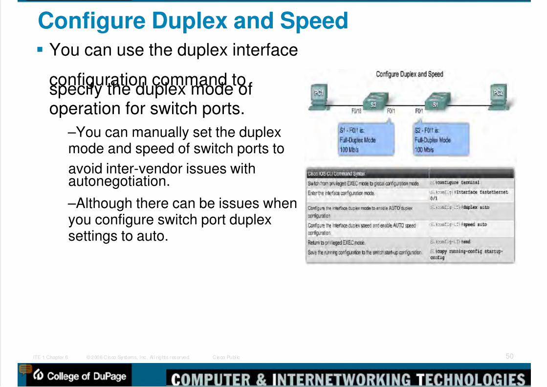
Configure Duplex and Speed You can use the duplex interface
configuration command tospecify the duplex mode ofoperation for switch ports.
–You can manually set the duplexmode and speed of switch ports to
avoid inter-vendor issues withautonegotiation.
–Although there can be issues whenyou configure switch port duplexsettings to auto.

5/9/2018 Exp3 LAN Switching Ch02-TonyChen - slidepdf.com
http://slidepdf.com/reader/full/exp3-lan-switching-ch02-tonychen 51/89
© 2006 Cisco Systems, Inc. Al l r ights reserved. Cisco Publ icITE 1 Chapter 6 51
Configure a Web Interface Modern Cisco switches have a number of web-
based configuration tools that require that the
switch is configured as an HTTP server. –These applications include the Cisco webbrowser user interface,
–Cisco Router and Security Device Manager(SDM),
–IP Phone and Cisco IOS Telephony Serviceapplications.
To control who can access the HTTP serviceson the switch, you can optionally configureauthentication.
–AAA and TACACS are authentication protocolsthat can be used in networks to validate usercredentials.
–You may need to have a less complex
authentication method.•The enable method requires users to use theserver's enable password.
•The local authentication method requires the userto use the login username, password, and privilegelevel access combination specified in the localsystem configuration (by the username globalconfiguration command).
5/9/2018 Exp3 LAN Switching Ch02-TonyChen - slidepdf.com
http://slidepdf.com/reader/full/exp3-lan-switching-ch02-tonychen 52/89
© 2006 Cisco Systems, Inc. Al l r ights reserved. Cisco Publ icITE 1 Chapter 6 52
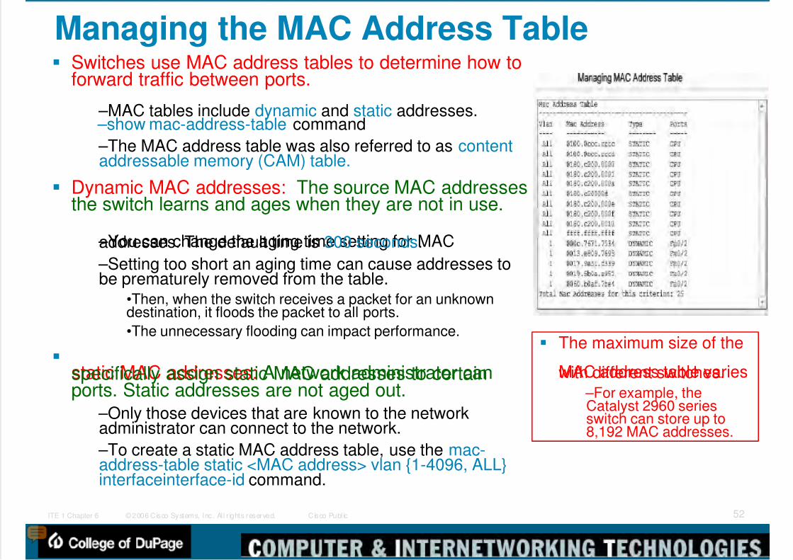
Managing the MAC Address Table Switches use MAC address tables to determine how to
forward traffic between ports.
–MAC tables include dynamic and static addresses. –show mac-address-table command
–The MAC address table was also referred to as contentaddressable memory (CAM) table.
Dynamic MAC addresses: The source MAC addressesthe switch learns and ages when they are not in use.
–You can change the aging time setting for MACaddresses. The default time is 300 seconds.
–Setting too short an aging time can cause addresses tobe prematurely removed from the table.
•Then, when the switch receives a packet for an unknowndestination, it floods the packet to all ports.
•The unnecessary flooding can impact performance.
static MAC addresses: A network administrator canspecifically assign static MAC addresses to certainports. Static addresses are not aged out.
–Only those devices that are known to the networkadministrator can connect to the network.
–To create a static MAC address table, use the mac-address-table static <MAC address> vlan {1-4096, ALL}interfaceinterface-id command.
The maximum size of the
MAC address table varieswith different switches. –For example, theCatalyst 2960 seriesswitch can store up to8,192 MAC addresses.

5/9/2018 Exp3 LAN Switching Ch02-TonyChen - slidepdf.com
http://slidepdf.com/reader/full/exp3-lan-switching-ch02-tonychen 53/89
© 2006 Cisco Systems, Inc. Al l r ights reserved. Cisco Publ icITE 1 Chapter 6 53
Using the Show Commands When you need to verify the configuration of your
Cisco switch, the show command is very useful.
One of the more valuable show commands is theshow running-config command.
–This command displays the configuration currentlyrunning on the switch. The output of the S1 switch:
•Fast Ethernet 0/18 interface configured with themanagement VLAN 99
•VLAN 99 configured with an IP address of 172.17.99.11255.255.0.0
•Default gateway set to 172.17.50.1
•HTTP server configured
Another commonly used command is the show
interfaces command. –The show interfaces command is used frequently whileconfiguring and monitoring network devices.
–The first highlighted line in the figure indicates that theFast Ethernet 0/1 interface is up and running.
–The next highlighted line shows that the duplex is auto-
duplex and the speed is auto-speed.
5/9/2018 Exp3 LAN Switching Ch02-TonyChen - slidepdf.com
http://slidepdf.com/reader/full/exp3-lan-switching-ch02-tonychen 54/89
© 2006 Cisco Systems, Inc. Al l r ights reserved. Cisco Publ icITE 1 Chapter 6 54
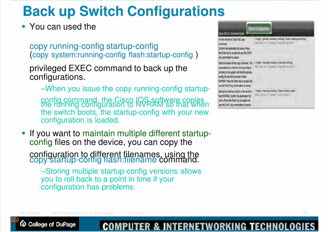
Back up Switch Configurations You can used the
copy running-config startup-config(copy system:running-config flash:startup-config )
privileged EXEC command to back up theconfigurations.
–When you issue the copy running-config startup-
config command, the Cisco IOS software copiesthe running configuration to NVRAM so that whenthe switch boots, the startup-config with your newconfiguration is loaded.
If you want to maintain multiple different startup-config files on the device, you can copy the
configuration to different filenames, using thecopy startup-config flash:filename command.
–Storing multiple startup-config versions allowsyou to roll back to a point in time if yourconfiguration has problems.

5/9/2018 Exp3 LAN Switching Ch02-TonyChen - slidepdf.com
http://slidepdf.com/reader/full/exp3-lan-switching-ch02-tonychen 55/89
© 2006 Cisco Systems, Inc. Al l r ights reserved. Cisco Publ icITE 1 Chapter 6 55
Restore Switch Configurations Restoring a configuration is a simple process. You just
need to copy the saved configuration over the currentconfiguration.
For example, you could restore saved configurationover your existing startup-config by entering this CiscoIOS command copy flash:config.bak1 startup-config.
–Once the configuration has been restored to the startup-config, you reload the switch so that it reloads the newstartup configuration.
After issuing the reload command, the system prompts youto answer whether or not to save the configuration.
Normally you would indicate "yes", but in this particular caseyou need to answer "no".
If you answered "yes", the file you just restored would beoverwritten.
In every case you need to consider whether or not the currentrunning configuration is the one you want to be active afterreload.
Note: There is also the option of entering the copystartup-config running-config command.
–Unfortunately, this command does not entirely overwrite therunning configuration;
–it only adds existing commands from the startupconfiguration to the running configuration. This can causeunintended results. Be careful when you do this.

5/9/2018 Exp3 LAN Switching Ch02-TonyChen - slidepdf.com
http://slidepdf.com/reader/full/exp3-lan-switching-ch02-tonychen 56/89
© 2006 Cisco Systems, Inc. Al l r ights reserved. Cisco Publ icITE 1 Chapter 6 56
Back up Configuration Files to a TFTP Server Having the configuration stored safely off the switch protects
it in the event there is some major catastrophic problem with
your switch. –You can use TFTP to back up your configuration files over thenetwork. Cisco IOS software comes with a built-in TFTP clientthat allows you to connect to a TFTP server on your network.
–One commonly used TFTP server is fromwww.solarwinds.com.
Backing up the Configuration
–Step 1. Verify that the TFTP server is running on your network.
–Step 2. Log in to the switch through the console port or aTelnet session. Enable the switch and then ping the TFTPserver.
–Step 3. Upload the switch configuration to the TFTP server.Specify the IP address or hostname of the TFTP server and thedestination filename. The Cisco IOS command is: #copysystem:running-config tftp:[[[//location]/directory]/filename] or#copy nvram:startup-config tftp:[[[//location]/directory]/filename].
or #copy startup-config tftp

5/9/2018 Exp3 LAN Switching Ch02-TonyChen - slidepdf.com
http://slidepdf.com/reader/full/exp3-lan-switching-ch02-tonychen 57/89
© 2006 Cisco Systems, Inc. Al l r ights reserved. Cisco Publ icITE 1 Chapter 6 57
Restoring the Configuration Files from a TFTP Server
Once the configuration is stored successfully on the TFTPserver, it can be copied back to the switch using the following
steps: –Step 1. Copy the configuration file to the appropriate TFTPdirectory on the TFTP server if it is not already there.
–Step 2. Verify that the TFTP server is running on your network.
–Step 3. Log in to the switch through the console port or a Telnetsession. Enable the switch and then ping the TFTP server.
–Step 4. Download the configuration file from the TFTP server toconfigure the switch. Specify the IP address or hostname of theTFTP server and the name of the file to download. The Cisco IOScommand is: #copy tftp:[[[//location]/directory]/filename]system:running-config or #copy tftp:[[[//location]/directory]/filename]nvram:startup-config.
If the configuration file is downloaded into the running-config,
the commands are executed as the file is parsed line by line. If the configuration file is downloaded into the startup-config,
the switch must be reloaded for the changes to take effect.
or #copy tftp startor #copy tftp run

5/9/2018 Exp3 LAN Switching Ch02-TonyChen - slidepdf.com
http://slidepdf.com/reader/full/exp3-lan-switching-ch02-tonychen 58/89
© 2006 Cisco Systems, Inc. Al l r ights reserved. Cisco Publ icITE 1 Chapter 6 58
Clearing Configuration Information Clearing Configuration File
–You might do this to prepare a used switch to beshipped to a customer or a different department andyou want to ensure that the switch getsreconfigured.
•When you erase the startup configuration filewhen the switch reboots, it enters the setupprogram so that you can reconfigure the switch
with new settings. –To clear the contents of your startup configuration,use the erase nvram: or the erase startup-configprivileged EXEC command.
Deleting a Stored Configuration File
–You may have been working on a complexconfiguration task and stored many backup copiesof your files in Flash. To delete a file from Flashmemory, use the delete flash:filename privilegedEXEC command.

5/9/2018 Exp3 LAN Switching Ch02-TonyChen - slidepdf.com
http://slidepdf.com/reader/full/exp3-lan-switching-ch02-tonychen 59/89
© 2006 Cisco Systems, Inc. Al l r ights reserved. Cisco Publ icITE 1 Chapter 6 59
Secure the Console Access Secure the Console
To secure the console port from unauthorized access, set apassword on the console port.
–Step 1. Switch from privileged EXEC mode to global configurationmode. Enter the configure terminal command.
–Step 2. Switch from global configuration mode to line configurationmode for console 0. The command prompt (config-line)#. Enter thecommand line console 0.
–Step 3. From line configuration mode, you can set the password forthe console by entering the password<password> command.
–Step 4. To ensure that a user on the console port is required to enter
the password, use the login command.•Even when a password is defined, it is not required to be entered until thelogin command has been issued.
–Step 5. Exit line configuration mode and return to privileged EXECmode using the end command.
Remove Console Password
If you need to remove the password use the following steps:
–Step 1. Enter the configure terminal command. –Step 2. Enter the command line console 0.
–Step 3. Remove the password from the console line using the nopassword command.
•Caution: If no password is defined and login is still enabled, there is STILLaccess to the console.
–Step 4. Remove the requirement to enter the password at login to theconsole line using the no login command.
–Step 5. Exit line configuration mode using the end command.
5/9/2018 Exp3 LAN Switching Ch02-TonyChen - slidepdf.com
http://slidepdf.com/reader/full/exp3-lan-switching-ch02-tonychen 60/89
© 2006 Cisco Systems, Inc. Al l r ights reserved. Cisco Publ icITE 1 Chapter 6 60
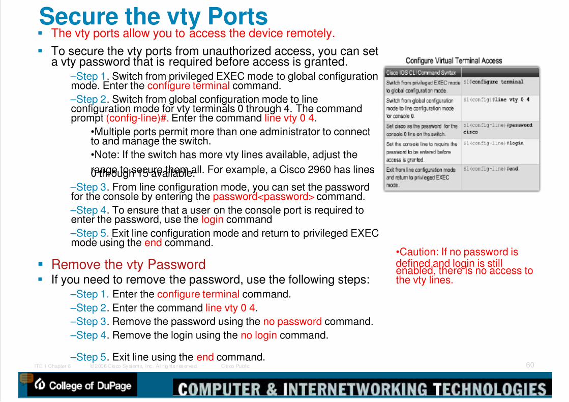
Secure the vty Ports The vty ports allow you to access the device remotely.
To secure the vty ports from unauthorized access, you can seta vty password that is required before access is granted.
–Step 1. Switch from privileged EXEC mode to global configurationmode. Enter the configure terminal command.
–Step 2. Switch from global configuration mode to lineconfiguration mode for vty terminals 0 through 4. The commandprompt (config-line)#. Enter the command line vty 0 4.
•Multiple ports permit more than one administrator to connectto and manage the switch.
•Note: If the switch has more vty lines available, adjust the
range to secure them all. For example, a Cisco 2960 has lines0 through 15 available.
–Step 3. From line configuration mode, you can set the passwordfor the console by entering the password<password> command.
–Step 4. To ensure that a user on the console port is required toenter the password, use the login command
–Step 5. Exit line configuration mode and return to privileged EXECmode using the end command.
Remove the vty Password If you need to remove the password, use the following steps:
–Step 1. Enter the configure terminal command.
–Step 2. Enter the command line vty 0 4.
–Step 3. Remove the password using the no password command.
–Step 4. Remove the login using the no login command.
–Step 5. Exit line using the end command.
•Caution: If no password isdefined and login is stillenabled, there is no access tothe vty lines.
5/9/2018 Exp3 LAN Switching Ch02-TonyChen - slidepdf.com
http://slidepdf.com/reader/full/exp3-lan-switching-ch02-tonychen 61/89
© 2006 Cisco Systems, Inc. Al l r ights reserved. Cisco Publ icITE 1 Chapter 6 61
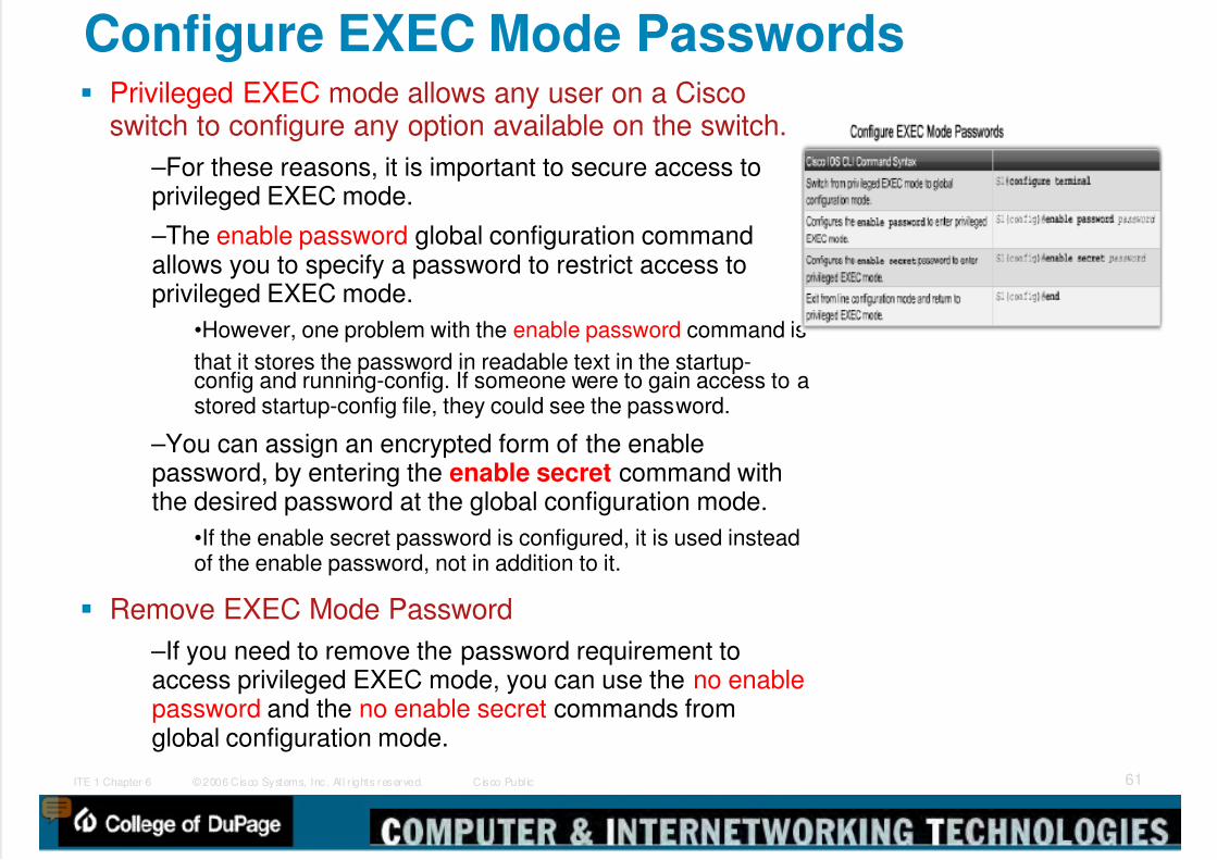
Configure EXEC Mode Passwords Privileged EXEC mode allows any user on a Cisco
switch to configure any option available on the switch.
–For these reasons, it is important to secure access toprivileged EXEC mode.
–The enable password global configuration commandallows you to specify a password to restrict access toprivileged EXEC mode.
•However, one problem with the enable password command is
that it stores the password in readable text in the startup-config and running-config. If someone were to gain access to astored startup-config file, they could see the password.
–You can assign an encrypted form of the enablepassword, by entering the enable secret command withthe desired password at the global configuration mode.
•If the enable secret password is configured, it is used insteadof the enable password, not in addition to it.
Remove EXEC Mode Password
–If you need to remove the password requirement toaccess privileged EXEC mode, you can use the no enablepassword and the no enable secret commands fromglobal configuration mode.

5/9/2018 Exp3 LAN Switching Ch02-TonyChen - slidepdf.com
http://slidepdf.com/reader/full/exp3-lan-switching-ch02-tonychen 62/89
© 2006 Cisco Systems, Inc. Al l r ights reserved. Cisco Publ icITE 1 Chapter 6 62
Configure Encrypted Passwords When configuring passwords in Cisco IOS CLI,
by default all passwords, except for the enable
secret password, are stored in clear text formatwithin the startup-config and running-config.
–It is universally accepted that passwords should beencrypted and not stored in clear text format.
–The Cisco IOS command service password-encryption enables service password encryption.
When the service password-encryption commandis entered from global configuration, all systempasswords are stored in an encrypted form.
–As soon as the command is entered, all currentlypasswords are converted to encrypted passwords.
If you want to remove the requirement to store all
system passwords in an encrypted format, enterthe no service password-encryption command.
Removing password encryption does not convertencrypted passwords back into readable text.
However, all newly set passwords are stored inclear text format.
5/9/2018 Exp3 LAN Switching Ch02-TonyChen - slidepdf.com
http://slidepdf.com/reader/full/exp3-lan-switching-ch02-tonychen 63/89
© 2006 Cisco Systems, Inc. Al l r ights reserved. Cisco Publ icITE 1 Chapter 6 63
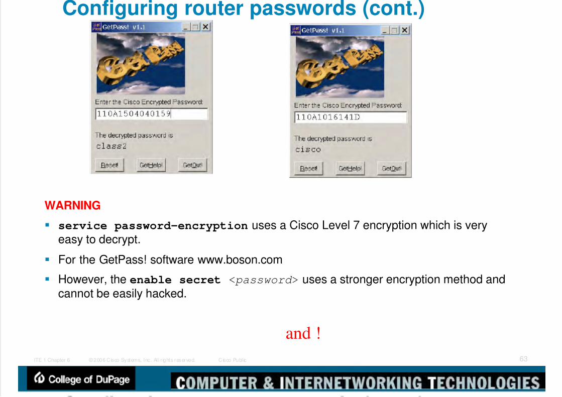
Configuring router passwords (cont.)
WARNING
service password-encryption uses a Cisco Level 7 encryption which is veryeasy to decrypt.
For the GetPass! software www.boson.com
However, the enable secret < password > uses a stronger encryption method andcannot be easily hacked.
and !
C fi i d ( )

5/9/2018 Exp3 LAN Switching Ch02-TonyChen - slidepdf.com
http://slidepdf.com/reader/full/exp3-lan-switching-ch02-tonychen 64/89
© 2006 Cisco Systems, Inc. Al l r ights reserved. Cisco Publ icITE 1 Chapter 6 64
Configuring router passwords (cont.)
Doesn’t work for enable secret!
http://www.boson.com/FreeUtilities.html
E bl P d R
5/9/2018 Exp3 LAN Switching Ch02-TonyChen - slidepdf.com
http://slidepdf.com/reader/full/exp3-lan-switching-ch02-tonychen 65/89
© 2006 Cisco Systems, Inc. Al l r ights reserved. Cisco Publ icITE 1 Chapter 6 65
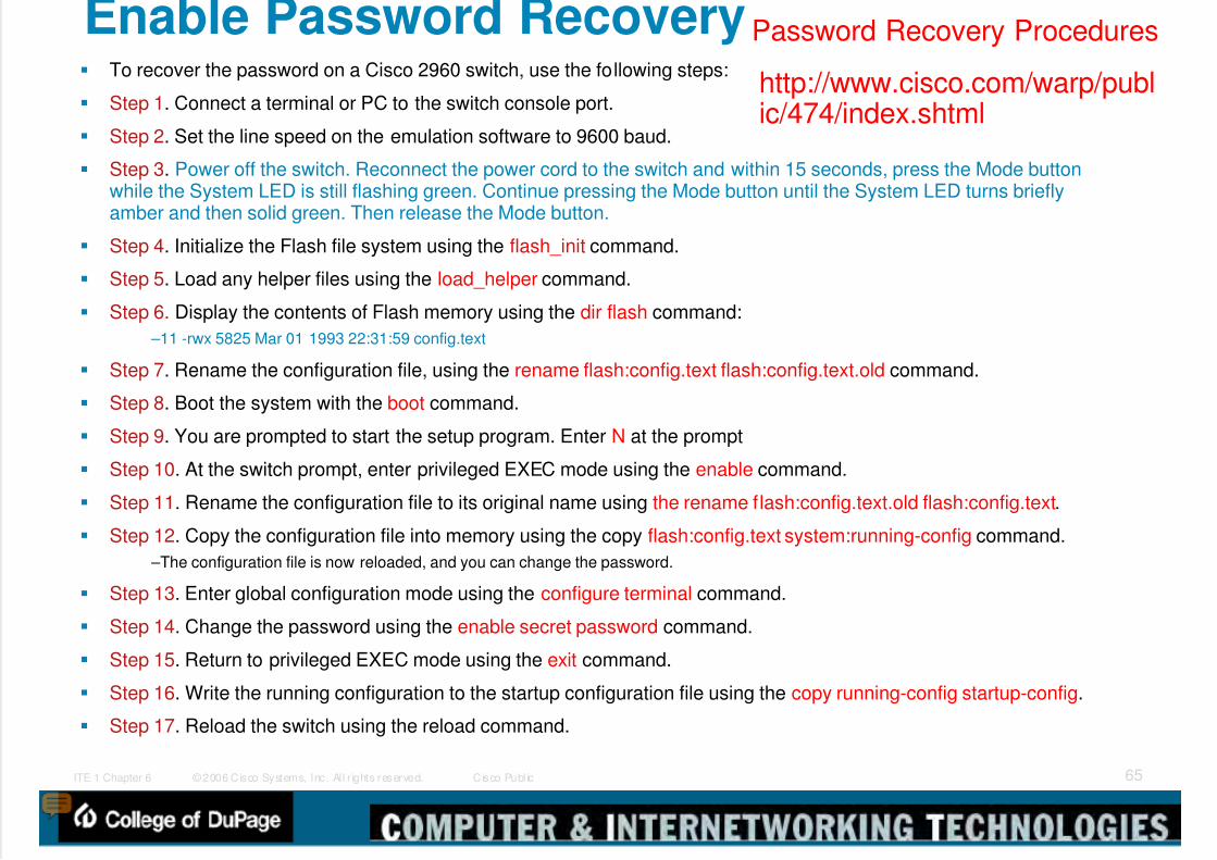
Enable Password Recovery To recover the password on a Cisco 2960 switch, use the following steps:
Step 1. Connect a terminal or PC to the switch console port.
Step 2. Set the line speed on the emulation software to 9600 baud.
Step 3. Power off the switch. Reconnect the power cord to the switch and within 15 seconds, press the Mode buttonwhile the System LED is still flashing green. Continue pressing the Mode button until the System LED turns brieflyamber and then solid green. Then release the Mode button.
Step 4. Initialize the Flash file system using the flash_init command.
Step 5. Load any helper files using the load_helper command.
Step 6. Display the contents of Flash memory using the dir flash command:
–11 -rwx 5825 Mar 01 1993 22:31:59 config.text
Step 7. Rename the configuration file, using the rename flash:config.text flash:config.text.old command.
Step 8. Boot the system with the boot command.
Step 9. You are prompted to start the setup program. Enter N at the prompt
Step 10. At the switch prompt, enter privileged EXEC mode using the enable command.
Step 11. Rename the configuration file to its original name using the rename flash:config.text.old flash:config.text.
Step 12. Copy the configuration file into memory using the copy flash:config.text system:running-config command.
–The configuration file is now reloaded, and you can change the password.
Step 13. Enter global configuration mode using the configure terminal command.
Step 14. Change the password using the enable secret password command.
Step 15. Return to privileged EXEC mode using the exit command.
Step 16. Write the running configuration to the startup configuration file using the copy running-config startup-config.
Step 17. Reload the switch using the reload command.
http://www.cisco.com/warp/public/474/index.shtml
Password Recovery Procedures

5/9/2018 Exp3 LAN Switching Ch02-TonyChen - slidepdf.com
http://slidepdf.com/reader/full/exp3-lan-switching-ch02-tonychen 66/89
© 2006 Cisco Systems, Inc. Al l r ights reserved. Cisco Publ icITE 1 Chapter 6 66
Configure a Login Banner The Cisco IOS command set includes a feature
that allows you to configure messages thatanyone logging onto the switch sees.
–These messages are called login banners andmessage of the day (MOTD) banners.
You can define a customized banner to be displayedbefore the username and password login prompts by
using the banner login command in globalconfiguration mode.
–The figure shows the S1 switch being configuredwith a login banner Authorized Personnel Only!
To remove the MOTD banner, enter the no format
of this command, –For example, S1(config)#no banner login.
banner login
5/9/2018 Exp3 LAN Switching Ch02-TonyChen - slidepdf.com
http://slidepdf.com/reader/full/exp3-lan-switching-ch02-tonychen 67/89
© 2006 Cisco Systems, Inc. Al l r ights reserved. Cisco Publ icITE 1 Chapter 6 67
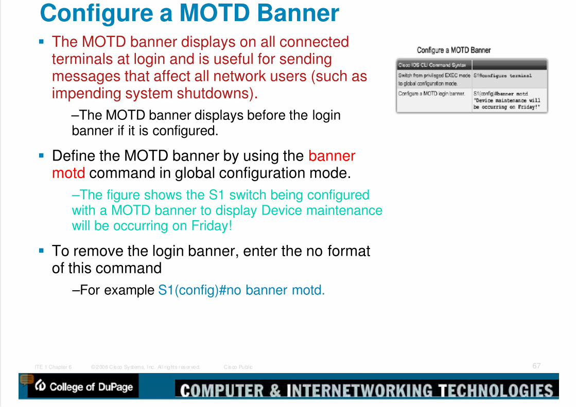
Configure a MOTD Banner The MOTD banner displays on all connected
terminals at login and is useful for sendingmessages that affect all network users (such asimpending system shutdowns).
–The MOTD banner displays before the loginbanner if it is configured.
Define the MOTD banner by using the bannermotd command in global configuration mode.
–The figure shows the S1 switch being configuredwith a MOTD banner to display Device maintenancewill be occurring on Friday!
To remove the login banner, enter the no formatof this command
–For example S1(config)#no banner motd.

5/9/2018 Exp3 LAN Switching Ch02-TonyChen - slidepdf.com
http://slidepdf.com/reader/full/exp3-lan-switching-ch02-tonychen 68/89
© 2006 Cisco Systems, Inc. Al l r ights reserved. Cisco Publ icITE 1 Chapter 6 68
Telnet and SSH There are two choices for remotely accessing a vty on a
Cisco switch.
Telnet: Telnet is a popular protocol used for terminalaccess because most current operating systems comewith a Telnet client built in.
–However, Telnet is an insecure way of accessing anetwork device, because it sends all communicationsacross the network in clear text.
–Using network monitoring software, an attacker can readevery keystroke that is sent between the Telnet client andthe Telnet service running on the Cisco switch.
SSH: SSH gives the same type of access as Telnet withthe added benefit of security.
–Communication between the SSH client and SSH serveris encrypted.
–Cisco devices supporting both SSHv1 and SSHv2.
•It is recommended that you implement SSHv2 whenpossible, because it uses a more enhanced securityencryption algorithm than SSHv1.
–Older switches may not support secure communicationwith Secure Shell (SSH).
enable secret ?

5/9/2018 Exp3 LAN Switching Ch02-TonyChen - slidepdf.com
http://slidepdf.com/reader/full/exp3-lan-switching-ch02-tonychen 69/89
© 2006 Cisco Systems, Inc. Al l r ights reserved. Cisco Publ icITE 1 Chapter 6 69
Configuring Telnet and SSH Because Telnet is the default transport for the vty lines, you
do not need to specify it after the initial configuration of the
switch has been performed. However, if you have switched the transport protocol on the
vty lines to permit only SSH, you need to enable the Telnetprotocol to permit Telnet access manually.
If you need to re-enable the Telnet protocol on a Cisco 2960switch, use the following command from line configurationmode:
–(config-line)#transport input telnet
–or
–(config-line)#transport input all.
By permitting all transport protocols, you still permit SSHaccess to the switch as well as Telnet access.
[Tony]: Prevent Non-SSH Connections•line vty 0 4•transport input ssh
–

5/9/2018 Exp3 LAN Switching Ch02-TonyChen - slidepdf.com
http://slidepdf.com/reader/full/exp3-lan-switching-ch02-tonychen 70/89
© 2006 Cisco Systems, Inc. Al l r ights reserved. Cisco Publ icITE 1 Chapter 6 70
Telnet and SSH and Banner The banner command output varies
between the Telnet and different versionsof SSH connections.
http://www.cisco.com/warp/public/707/ssh.shtml
C fi i SSH

5/9/2018 Exp3 LAN Switching Ch02-TonyChen - slidepdf.com
http://slidepdf.com/reader/full/exp3-lan-switching-ch02-tonychen 71/89
© 2006 Cisco Systems, Inc. Al l r ights reserved. Cisco Publ icITE 1 Chapter 6 71
Configuring SSH SSH is a cryptographic security feature that is subject to export
restrictions. To use this feature, a cryptographic image must beinstalled on your switch.
–The SSH feature has an SSH server and an SSH integrated client,which are applications that run on the switch. You can use any SSHclient running on a PC or the Cisco SSH client running on the switch toconnect to a switch.
–The switch supports SSHv1 or SSHv2 for the server component.
–The switch supports only SSHv1 for the client component.
Beginning in privileged EXEC mode, follow these steps.
Step 1. Enter global configuration mode using configure terminal. Step 2. Configure a hostname for your switch using the hostname.
Step 3. Configure a host domain for your switch using the ipdomain-name domain_name command.
Step 4. Enable the SSH server on the switch and generate an RSAkey pair using the crypto key generate rsa command.
–When you generate RSA keys, you are prompted to enter a moduluslength. Cisco recommends using a modulus size of 1024 bits.
–To delete the RSA key pair, use the crypto key zeroize rsa globalconfiguration command.
Step 5. Return to privileged EXEC mode using the end command.
Step 6. Show the status of the SSH server on the switch using theshow ip ssh or show ssh command.

5/9/2018 Exp3 LAN Switching Ch02-TonyChen - slidepdf.com
http://slidepdf.com/reader/full/exp3-lan-switching-ch02-tonychen 72/89
© 2006 Cisco Systems, Inc. Al l r ights reserved. Cisco Publ icITE 1 Chapter 6 72
Configuring SSH Server Follow these steps to configure the SSH server.
Step 1. Enter global configuration using the configure terminal command.
Step 2. (Optional) Configure the switch to run SSHv1 or SSHv2 using theip ssh version [1 | 2] command.
Step 3. Configure the SSH control parameters:
–Specify the time-out value in seconds; the default is 120 seconds.
•parameter applies to the SSH negotiation phase.
–By default, up to five simultaneous, encrypted SSH connections.
–The CLI-based session time-out value returns to the default of 10 minutes. –Specify the number of times that a client can re-authenticate to the server. Thedefault is 3; the range is 0 to 5.
–To configure both parameters use the ip ssh {timeoutseconds | authentication-retriesnumber} command.
Step 4. Return to privileged EXEC mode using the end command.
Step 5. Display the status of the SSH server connections on the switch
using the show ip ssh or the show ssh command. Step 6. (Optional) Save your entries in the configuration file using the
copy running-config startup-config command.
If you want to prevent non-SSH connections, add the transport input sshcommand in line configuration mode to limit the switch to SSHconnections only.
–Straight (non-SSH) Telnet connections are refused.
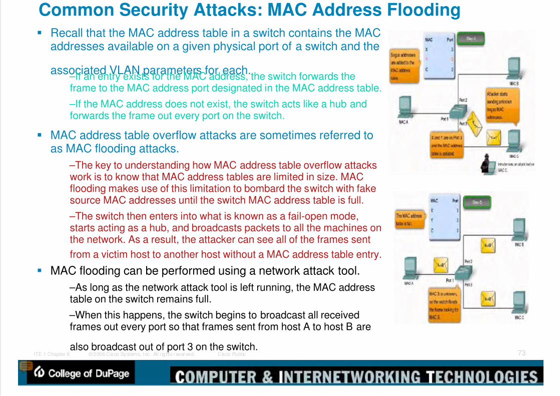
5/9/2018 Exp3 LAN Switching Ch02-TonyChen - slidepdf.com
http://slidepdf.com/reader/full/exp3-lan-switching-ch02-tonychen 73/89
© 2006 Cisco Systems, Inc. Al l r ights reserved. Cisco Publ icITE 1 Chapter 6 73
Common Security Attacks: MAC Address Flooding Recall that the MAC address table in a switch contains the MAC
addresses available on a given physical port of a switch and the
associated VLAN parameters for each. –If an entry exists for the MAC address, the switch forwards theframe to the MAC address port designated in the MAC address table.
–If the MAC address does not exist, the switch acts like a hub andforwards the frame out every port on the switch.
MAC address table overflow attacks are sometimes referred toas MAC flooding attacks.
–The key to understanding how MAC address table overflow attackswork is to know that MAC address tables are limited in size. MACflooding makes use of this limitation to bombard the switch with fakesource MAC addresses until the switch MAC address table is full.
–The switch then enters into what is known as a fail-open mode,starts acting as a hub, and broadcasts packets to all the machines onthe network. As a result, the attacker can see all of the frames sent
from a victim host to another host without a MAC address table entry.
MAC flooding can be performed using a network attack tool.
–As long as the network attack tool is left running, the MAC addresstable on the switch remains full.
–When this happens, the switch begins to broadcast all receivedframes out every port so that frames sent from host A to host B are
also broadcast out of port 3 on the switch.

5/9/2018 Exp3 LAN Switching Ch02-TonyChen - slidepdf.com
http://slidepdf.com/reader/full/exp3-lan-switching-ch02-tonychen 74/89
© 2006 Cisco Systems, Inc. Al l r ights reserved. Cisco Publ icITE 1 Chapter 6 74
Common Security Attacks: Spoofing Attacks One way an attacker can gain access to network traffic is to spoof
responses that would be sent by a valid DHCP server.
–The DHCP spoofing device replies to client DHCP requests. –The legitimate server may also reply, but if the spoofing device is on the samesegment as the client, its reply to the client may arrive first.
–The intruder DHCP reply offers an IP address and supporting information thatdesignates the intruder as the default gateway or Domain Name System (DNS)server.
–In the case of a gateway, the clients then forward packets to the attackingdevice, which in turn, sends them to the desired destination. This is referred toas a man-in-the-middle attack, and it may go entirely undetected as the intruderintercepts the data flow through the network.
You should be aware of another type of DHCP attack called a DHCPstarvation attack.
–The attacker PC continually requests IP addresses from a real DHCP serverby changing their source MAC addresses.
–If successful, this kind of DHCP attack causes all of the leases on the realDHCP server to be allocated, thus preventing the real users (DHCP clients)
from obtaining an IP address.
S fi A k
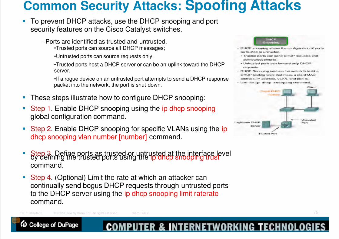
5/9/2018 Exp3 LAN Switching Ch02-TonyChen - slidepdf.com
http://slidepdf.com/reader/full/exp3-lan-switching-ch02-tonychen 75/89
© 2006 Cisco Systems, Inc. Al l r ights reserved. Cisco Publ icITE 1 Chapter 6 75
Common Security Attacks: Spoofing Attacks To prevent DHCP attacks, use the DHCP snooping and port
security features on the Cisco Catalyst switches.
–Ports are identified as trusted and untrusted.•Trusted ports can source all DHCP messages;
•Untrusted ports can source requests only.
•Trusted ports host a DHCP server or can be an uplink toward the DHCPserver.
•If a rogue device on an untrusted port attempts to send a DHCP responsepacket into the network, the port is shut down.
These steps illustrate how to configure DHCP snooping:
Step 1. Enable DHCP snooping using the ip dhcp snoopingglobal configuration command.
Step 2. Enable DHCP snooping for specific VLANs using the ipdhcp snooping vlan number [number] command.
Step 3. Define ports as trusted or untrusted at the interface levelby defining the trusted ports using the ip dhcp snooping trustcommand.
Step 4. (Optional) Limit the rate at which an attacker cancontinually send bogus DHCP requests through untrusted portsto the DHCP server using the ip dhcp snooping limit rateratecommand.
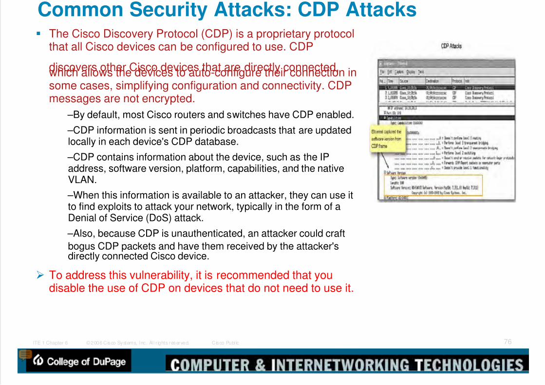
5/9/2018 Exp3 LAN Switching Ch02-TonyChen - slidepdf.com
http://slidepdf.com/reader/full/exp3-lan-switching-ch02-tonychen 76/89
© 2006 Cisco Systems, Inc. Al l r ights reserved. Cisco Publ icITE 1 Chapter 6 76
Common Security Attacks: CDP Attacks The Cisco Discovery Protocol (CDP) is a proprietary protocol
that all Cisco devices can be configured to use. CDP
discovers other Cisco devices that are directly connected,which allows the devices to auto-configure their connection insome cases, simplifying configuration and connectivity. CDPmessages are not encrypted.
–By default, most Cisco routers and switches have CDP enabled.
–CDP information is sent in periodic broadcasts that are updatedlocally in each device's CDP database.
–CDP contains information about the device, such as the IPaddress, software version, platform, capabilities, and the nativeVLAN.
–When this information is available to an attacker, they can use itto find exploits to attack your network, typically in the form of aDenial of Service (DoS) attack.
–Also, because CDP is unauthenticated, an attacker could craft
bogus CDP packets and have them received by the attacker'sdirectly connected Cisco device.
To address this vulnerability, it is recommended that youdisable the use of CDP on devices that do not need to use it.

5/9/2018 Exp3 LAN Switching Ch02-TonyChen - slidepdf.com
http://slidepdf.com/reader/full/exp3-lan-switching-ch02-tonychen 77/89
© 2006 Cisco Systems, Inc. Al l r ights reserved. Cisco Publ icITE 1 Chapter 6 77
Common Security Attacks: Telnet Attacks Telnet Attacks
–The Telnet protocol can be used by an attacker to gain remote access
to a Cisco network switch.•In an earlier topic, you configured a login password for the vty lines and set thelines to require password authentication to gain access.
•There are tools available that allow an attacker to launch a brute forcepassword cracking attack against the vty lines on the switch.
Brute Force Password Attack
–The first phase of a brute force password attack starts with the attacker
using a list of common passwords and a program designed to try toestablish a Telnet session using each word on the dictionary list.
–In the second phase of a brute force attack, the attacker uses aprogram that creates sequential character combinations in an attempt to"guess" the password. Given enough time, a brute force password attackcan crack almost all passwords used.
–The simplest thing that you can do to limit the vulnerability to brute force
password attacks is use strong passwords randomly mixing upper andlowercase letters with numerals.
DoS Attack
–In a DoS attack, the attacker exploits a flaw in the Telnet softwarerunning on the switch that renders the Telnet service unavailable.
–If you are experiencing a DoS attack against the Telnet service, check
to see if there is a newer Cisco IOS revision available.
S it T l

5/9/2018 Exp3 LAN Switching Ch02-TonyChen - slidepdf.com
http://slidepdf.com/reader/full/exp3-lan-switching-ch02-tonychen 78/89
© 2006 Cisco Systems, Inc. Al l r ights reserved. Cisco Publ icITE 1 Chapter 6 78
Security Tools Network security tools help you test your network weaknesses.
Network Security Audit
–Network security tools allow you to perform a security audit of your network.
–A security audit reveals what sort of information an attacker can gathersimply by monitoring network traffic.
–Network security auditing tools allow you to flood the MAC table with bogusMAC addresses.
–Then you can audit the switch ports as the switch starts flooding traffic out allports as the legitimate MAC address mappings are aged out and replacedwith more bogus MAC address mappings.
–In this way, you can determine which ports are compromised and have notbeen correctly configured to prevent this type of attack.
Network Penetration Testing
–Network security tools can also be used for penetration testing against yournetwork. This allows you to identify weaknesses within the configuration ofyour networking devices.
–There are numerous attacks that you can perform, and most tool suites
come with extensive documentation detailing the syntax needed to executethe desired attack.
–Because these types of tests can have adverse effects on the network, theyare carried out under very controlled conditions, following documentedprocedures detailed in a comprehensive network security policy.
–Of course, if you have a small classroom-based network, you can arrange towork with your instructor to try your own network penetration tests.

5/9/2018 Exp3 LAN Switching Ch02-TonyChen - slidepdf.com
http://slidepdf.com/reader/full/exp3-lan-switching-ch02-tonychen 79/89
© 2006 Cisco Systems, Inc. Al l r ights reserved. Cisco Publ icITE 1 Chapter 6 79
Network Security Tools Features A secure network really is a process not a product. You cannot
just enable a switch with a secure configuration and declare the job done. Common features of a network security tool include:
–Service identification: Tools are used to target hosts using the IANAport numbers. These tools should also be able to discover FTPserver or WEB server running on a non-standard port (8080).
–Support of SSL services: Testing services that use SSL levelsecurity, including HTTPS, SMTPS, IMAPS, and security certificate.
–Non-destructive and destructive testing: Performing non-destructive
security audits on a routine basis that do not compromise or onlymoderately compromise network performance.
–Database of vulnerabilities: Vulnerabilities change all the time.
You can use network security tools to:
–Capture chat messages
–Capture files from NFS traffic
–Capture HTTP requests in Common Log Format –Capture mail messages in Berkeley mbox format
–Capture passwords
–Display captured URLs in browser in real time
–Flood a switched LAN with random MAC addresses
–Forge replies to DNS address / pointer queries
–Intercept packets on a switched LAN
Using Port Security to Mitigate Attacks

5/9/2018 Exp3 LAN Switching Ch02-TonyChen - slidepdf.com
http://slidepdf.com/reader/full/exp3-lan-switching-ch02-tonychen 80/89
© 2006 Cisco Systems, Inc. Al l r ights reserved. Cisco Publ icITE 1 Chapter 6 80
Using Port Security to Mitigate Attacks
Port security limits the number of valid MAC addressesallowed on a port.
–When you assign secure MAC addresses to a secure port,the port does not forward packets with source addressesoutside the group of defined addresses.
–If a port is configured as a secure port and the maximumnumber of secure MAC addresses is reached, a securityviolation occurs
The following describes the ways to configure port security –Static secure MAC addresses:
•MAC addresses are manually configured using the switchport port-security mac-addressmac-address interface command.
•MAC addresses configured in this way are stored in the addresstable and are added to the running configuration.
–Dynamic secure MAC addresses:•MAC addresses are dynamically learned and stored only in theaddress table. MAC addresses configured in this way are removedwhen the switch restarts.
–Sticky secure MAC addresses:
•You can configure a port to dynamically learn MAC addresses andthen save the MAC addresses to the running configuration.
S i k MAC Add

5/9/2018 Exp3 LAN Switching Ch02-TonyChen - slidepdf.com
http://slidepdf.com/reader/full/exp3-lan-switching-ch02-tonychen 81/89
© 2006 Cisco Systems, Inc. Al l r ights reserved. Cisco Publ icITE 1 Chapter 6 81
Using Port Security: Sticky MAC Addresses Sticky secure MAC addresses have these characteristics:
–When you enable sticky learning on an interface by using the switchport port-security mac-
address sticky interface configuration command,•the interface converts all the dynamic secure MAC addresses, including those that were dynamically learnedbefore sticky learning was enabled, to sticky secure MAC addresses and adds all sticky secure MACaddresses to the running configuration.
–If you disable sticky learning by using the no switchport port-security mac-address sticky interfaceconfiguration command or the running configuration is removed, the sticky secure MAC addressesremain part of the running configuration but are removed from the address table.
•The addresses that were removed can be dynamically reconfigured and added to the address table asdynamic addresses.
–When you configure sticky secure MAC addresses by using the switchport port-security mac-address sticky mac-address interface configuration command,
•these addresses are added to the address table and the running configuration. If port security is disabled, thesticky secure MAC addresses remain in the running configuration.
–If you save the sticky secure MAC addresses in the configuration file, when the switch restarts orthe interface shuts down, the interface does not need to relearn these addresses. If you do not
save the sticky secure addresses, they are lost.•If sticky learning is disabled, the sticky secure MAC addresses are converted to dynamic secure addressesand are removed from the running configuration.
–If you disable sticky learning and enter the switchport port-security mac-address sticky mac-address interface configuration command, an error message appears, and the sticky secure MACaddress is not added to the running configuration.
U i P S i S i Vi l i M d

5/9/2018 Exp3 LAN Switching Ch02-TonyChen - slidepdf.com
http://slidepdf.com/reader/full/exp3-lan-switching-ch02-tonychen 82/89
© 2006 Cisco Systems, Inc. Al l r ights reserved. Cisco Publ icITE 1 Chapter 6 82
Using Port Security: Security Violation Modes It is a security violation when either of these situations occurs:
–The maximum number of secure MAC addresses have been added to
the address table, and a station whose MAC address is not in theaddress table attempts to access the interface.
–An address learned or configured on one secure interface is seen onanother secure interface in the same VLAN.
You can configure the interface for one of 3 violation modes:
–protect: Packets with unknown source addresses are dropped untilyou remove a sufficient number of secure MAC addresses or increasethe number of maximum allowable addresses.
•You are not notified that a security violation has occurred.
–restrict: Packets with unknown source addresses are dropped untilyou remove a sufficient number of secure MAC addresses or increasethe number of maximum allowable addresses.
•In this mode, you are notified that a security violation has occurred.
•Specifically, an SNMP trap is sent, a syslog message is logged, and theviolation counter increments.
–shutdown: In this mode, a port security violation causes the interfaceto immediately become error-disabled and turns off the port LED.
•It also sends an SNMP trap, logs a syslog message, and increments theviolation counter.
•When a secure port is in the error-disabled state, you can bring it out of thisstate by entering the shutdown and no shutdown interface commands.
C fi P t S it
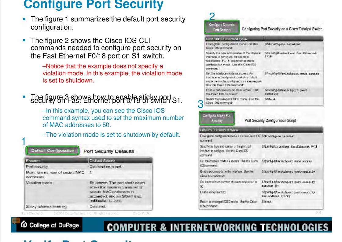
5/9/2018 Exp3 LAN Switching Ch02-TonyChen - slidepdf.com
http://slidepdf.com/reader/full/exp3-lan-switching-ch02-tonychen 83/89
© 2006 Cisco Systems, Inc. Al l r ights reserved. Cisco Publ icITE 1 Chapter 6 83
Configure Port Security The figure 1 summarizes the default port security
configuration.
The figure 2 shows the Cisco IOS CLIcommands needed to configure port security onthe Fast Ethernet F0/18 port on S1 switch.
–Notice that the example does not specify aviolation mode. In this example, the violation modeis set to shutdown.
The figure 3 shows how to enable sticky portsecurity on Fast Ethernet port 0/18 of switch S1.
–In this example, you can see the Cisco IOScommand syntax used to set the maximum numberof MAC addresses to 50.
–The violation mode is set to shutdown by default.
1
2
3
V if P t S it
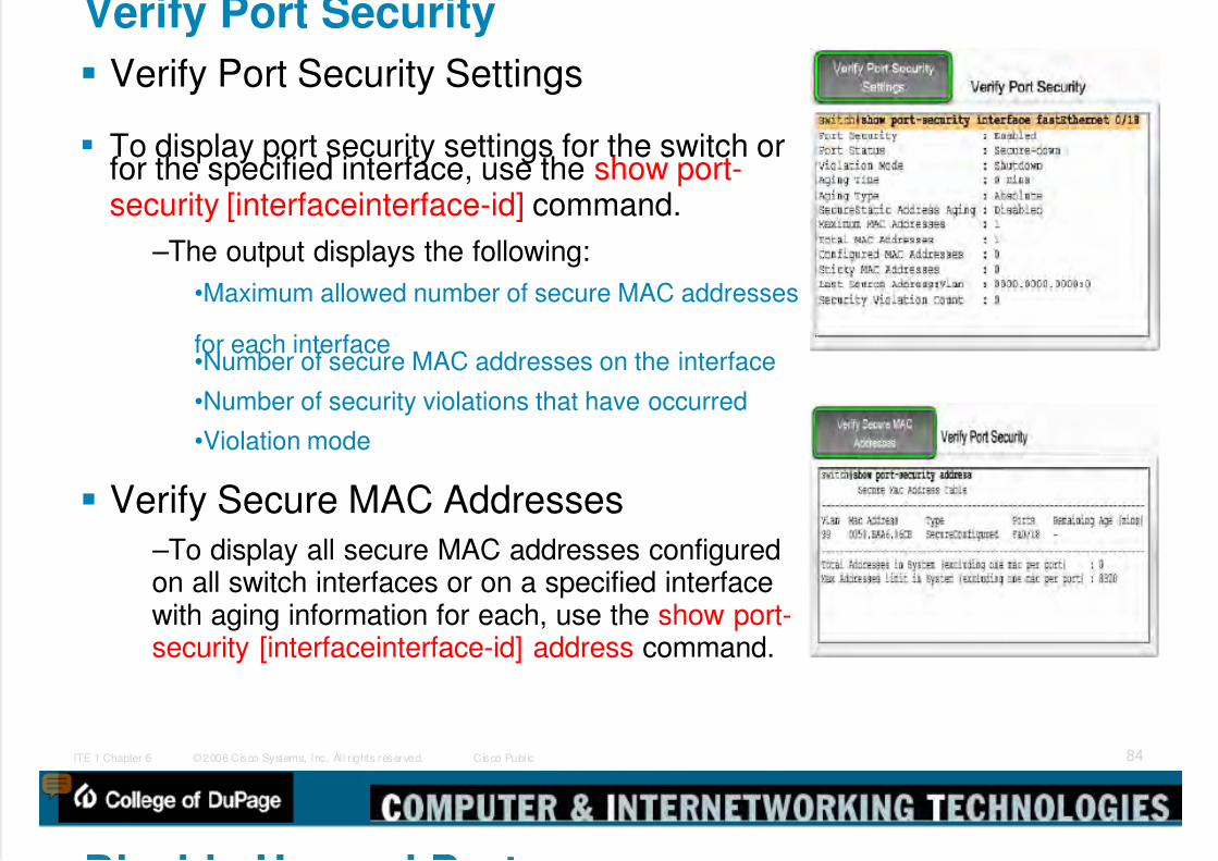
5/9/2018 Exp3 LAN Switching Ch02-TonyChen - slidepdf.com
http://slidepdf.com/reader/full/exp3-lan-switching-ch02-tonychen 84/89
© 2006 Cisco Systems, Inc. Al l r ights reserved. Cisco Publ icITE 1 Chapter 6 84
Verify Port Security
Verify Port Security Settings
To display port security settings for the switch orfor the specified interface, use the show port-security [interfaceinterface-id] command.
–The output displays the following:
•Maximum allowed number of secure MAC addresses
for each interface•Number of secure MAC addresses on the interface
•Number of security violations that have occurred
•Violation mode
Verify Secure MAC Addresses
–To display all secure MAC addresses configuredon all switch interfaces or on a specified interfacewith aging information for each, use the show port-security [interfaceinterface-id] address command.
Di bl U d P t

5/9/2018 Exp3 LAN Switching Ch02-TonyChen - slidepdf.com
http://slidepdf.com/reader/full/exp3-lan-switching-ch02-tonychen 85/89
© 2006 Cisco Systems, Inc. Al l r ights reserved. Cisco Publ icITE 1 Chapter 6 85
Disable Unused Ports A simple method many administrators
use to help secure their network from
unauthorized access is to disable allunused ports on a network switch.
–For example, imagine that a Cisco 2960switch has 24 ports. If there are three FastEthernet connections in use, good securitypractice demands that you disable the 21
unused ports.•It is simple to disable multiple ports on aswitch. Navigate to each unused port andissue this shutdown command.
•An alternate way to shutdown multipleports is to use the interface range
command.•If a port needs to be activated, you canmanually enter the no shutdown commandon that interface.
5/9/2018 Exp3 LAN Switching Ch02-TonyChen - slidepdf.com
http://slidepdf.com/reader/full/exp3-lan-switching-ch02-tonychen 86/89
© 2006 Cisco Systems, Inc. Al l r ights reserved. Cisco Publ icITE 1 Chapter 6 86
Summary
LAN Design
Process that explains how a LAN is to beimplemented
Factors to consider in LAN design include
Collision domains
Broadcast domains
Network latency
LAN segmentation

5/9/2018 Exp3 LAN Switching Ch02-TonyChen - slidepdf.com
http://slidepdf.com/reader/full/exp3-lan-switching-ch02-tonychen 87/89
© 2006 Cisco Systems, Inc. Al l r ights reserved. Cisco Publ icITE 1 Chapter 6 87
Summary
Switch forwarding methods
Store & forward – used by Cisco Catalyst switches
Cut through – 2 types
Cut through
Fast forwarding

5/9/2018 Exp3 LAN Switching Ch02-TonyChen - slidepdf.com
http://slidepdf.com/reader/full/exp3-lan-switching-ch02-tonychen 88/89
© 2006 Cisco Systems, Inc. Al l r ights reserved. Cisco Publ icITE 1 Chapter 6 88
Summary
Symmetric switching
Switching is conducted between ports that have thesame bandwidth
Asymmetric switching
Switching is conducted between ports that haveunlike bandwidth
5/9/2018 Exp3 LAN Switching Ch02-TonyChen - slidepdf.com
http://slidepdf.com/reader/full/exp3-lan-switching-ch02-tonychen 89/89
Tony Chen COD
Cisco Networking Academy
Summary
CISCO IOS CLI includes the following features
Built in help
Command history/options
Switch security
Password protection
Use of SSH for remote access
Port security