expedited permit process for pv systems · that have adopted the expedited permit process for pv...
TRANSCRIPT

Expedited Permit Process for PV Systems 6
Expedited Permit Process for PV Systems
The Solar America Board for Codes and Standards (Solar ABCs) Expedited Permit Pro-cess provides a means to differentiate systems that can be permitted quickly and easily due to their similarity with the majority of small-scale PV systems. Those systems with unique characteristics may be handled with small additions to this Expedited Permit Process or may require much more information, depending on the uniqueness of the installation.
The following pages contain forms to use with the Expedited Permit Process. The forms are available as interactive PDF files at www.solarabcs.org/permitting. In jurisdictionsthat have adopted the Expedited Permit Process for PV Systems, these forms can be filled out electronically and submitted in either printed form and via email. An electronic format is used so that the supplied information is standardized and legible for the local jurisdiction.
7Solar America Board for Codes and Standards Report
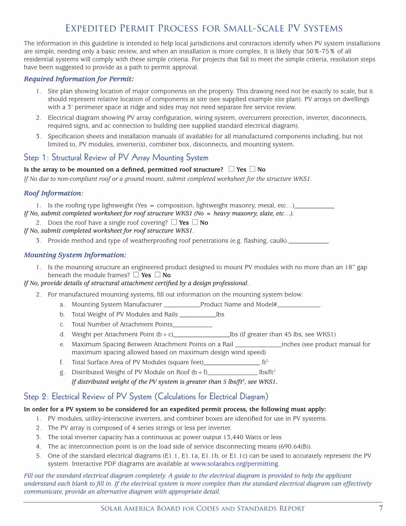
Expedited Permit Process for Small-Scale PV SystemsThe information in this guideline is intended to help local jurisdictions and contractors identify when PV system installations are simple, needing only a basic review, and when an installation is more complex. It is likely that 50%-75% of all residential systems will comply with these simple criteria. For projects that fail to meet the simple criteria, resolution steps have been suggested to provide as a path to permit approval.
Required Information for Permit:
1. Site plan showing location of major components on the property. This drawing need not be exactly to scale, but it should represent relative location of components at site (see supplied example site plan). PV arrays on dwellings with a 3’ perimeter space at ridge and sides may not need separate fire service review.
2. Electrical diagram showing PV array configuration, wiring system, overcurrent protection, inverter, disconnects, required signs, and ac connection to building (see supplied standard electrical diagram).
3. Specification sheets and installation manuals (if available) for all manufactured components including, but not limited to, PV modules, inverter(s), combiner box, disconnects, and mounting system.
Step 1: Structural Review of PV Array Mounting SystemIs the array to be mounted on a defined, permitted roof structure? l Yes l NoIf No due to non-compliant roof or a ground mount, submit completed worksheet for the structure WKS1.
Roof Information:
1. Is the roofing type lightweight (Yes = composition, lightweight masonry, metal, etc…)____________If No, submit completed worksheet for roof structure WKS1 (No = heavy masonry, slate, etc…).
2. Does the roof have a single roof covering? l Yes l NoIf No, submit completed worksheet for roof structure WKS1.
3. Provide method and type of weatherproofing roof penetrations (e.g. flashing, caulk).____________
Mounting System Information:
1. Is the mounting structure an engineered product designed to mount PV modules with no more than an 18” gap beneath the module frames? l Yes l No
If No, provide details of structural attachment certified by a design professional.
2. For manufactured mounting systems, fill out information on the mounting system below:
a. Mounting System Manufacturer ___________Product Name and Model#_____________
b. Total Weight of PV Modules and Rails ___________lbs
c. Total Number of Attachment Points____________
d. Weight per Attachment Point (b÷c)_________________lbs (if greater than 45 lbs, see WKS1)
e. Maximum Spacing Between Attachment Points on a Rail ______________inches (see product manual for maximum spacing allowed based on maximum design wind speed)
f. Total Surface Area of PV Modules (square feet)_________________ ft2
g. Distributed Weight of PV Module on Roof (b÷f)_______________ lbs/ft2
If distributed weight of the PV system is greater than 5 lbs/ft2, see WKS1.
Step 2: Electrical Review of PV System (Calculations for Electrical Diagram)In order for a PV system to be considered for an expedited permit process, the following must apply:
1. PV modules, utility-interactive inverters, and combiner boxes are identified for use in PV systems.2. The PV array is composed of 4 series strings or less per inverter.3. The total inverter capacity has a continuous ac power output 13,440 Watts or less4. The ac interconnection point is on the load side of service disconnecting means (690.64(B)).5. One of the standard electrical diagrams (E1.1, E1.1a, E1.1b, or E1.1c) can be used to accurately represent the PV
system. Interactive PDF diagrams are available at www.solarabcs.org/permitting.
Fill out the standard electrical diagram completely. A guide to the electrical diagram is provided to help the applicant understand each blank to fill in. If the electrical system is more complex than the standard electrical diagram can effectively communicate, provide an alternative diagram with appropriate detail.

Expedited Permit Process for PV Systems 8
Site Plan

9Solar America Board for Codes and Standards Report
Site Plan
Stand
ard
Electr
ical D
iagr
am

Expedited Permit Process for PV Systems 10
No
tes for
Electr
ical D
iagr
am
Contractor N
ame,
Address and Phone:
____________________________________________________________________
Notes for O
ne-Line Standard E
lectricalD
iagram for S
ingle-Phase P
V S
ystems
Site N
ame: __________________________
Site A
ddress: ________________________System
AC Size: ______________________
SIZEFS
CM
NO
DW
G N
OR
EV
E1.2
SCA
LEN
TSD
ate:S
HE
ET
Draw
n By:
Checked B
y:
MA
X P
OW
ER
-PO
INT C
UR
RE
NT (IM
P )
MA
X P
OW
ER
-POIN
T VOLTA
GE
(VM
P )
OP
EN
-CIR
CU
IT VO
LTAGE (V
OC )
SH
OR
T-CIR
CU
IT CU
RR
EN
T (ISC )
MA
X S
ER
IES FU
SE (O
CP
D)
MA
XIM
UM
POW
ER
(PM
AX )
MA
X V
OLTAG
E (TYP
600VD
C )
VO
C TE
MP
CO
EFF (mV
/ oC or %
/ oC )
IF CO
EFF SU
PPLIED
, CIR
CLE U
NITS
AVVAAWV
MO
DU
LE M
AKE
MO
DU
LE M
OD
EL
PV
MO
DU
LE R
ATIN
GS
@ S
TC (G
uide Section 5)
MAX
DC
VO
LT RA
TING
MAX
POW
ER
@ 40
oC
NO
MIN
AL A
C V
OLTAG
E
MAX
AC C
UR
REN
T
MAX
OC
PD R
ATIN
G
VWVAA
INV
ER
TER M
AKE
INV
ER
TER M
OD
EL
INV
ER
TER
RA
TING
S (G
uide Section 4)
1) IF UTILITY R
EQU
IRES
A VISIB
LE-BR
EAK
SWITC
H, D
OES
THIS S
WITC
H M
EET TH
ER
EQU
IREM
ENT? Y
ESN
ON
/A
2) IF GE
NE
RATIO
N M
ETER
REQ
UIR
ED, D
OE
S TH
IS M
ETER
SOC
KET M
EET TH
ER
EQU
IREM
ENT? Y
ESN
ON
/A
3) SIZE
PH
OTO
VOLTA
IC P
OW
ER
SO
UR
CE
(DC
) CO
ND
UC
TOR
S BAS
ED
ON
MA
XC
UR
RE
NT O
N N
EC
690.53 SIG
N O
R O
CP
D R
ATIN
G A
T DIS
CO
NN
EC
T
4) SIZE
INV
ER
TER O
UTP
UT C
IRC
UIT (AC
) CO
ND
UC
TOR
S A
CC
OR
DIN
G TO
INV
ERTE
RO
CP
D A
MP
ERE
RA
TING
. (See G
uide Section 9)
5) TOTA
L OF ______ IN
VER
TER
OC
PD
(s), ON
E FO
R E
ACH
INVE
RTE
R. D
OES
TOTAL
SU
PP
LY BR
EAK
ERS C
OM
PLY W
ITH 120%
BU
SB
AR EX
CE
PTIO
N IN
690.64(B)(2)(a)?
YES
NO
NO
TES
FOR
INV
ER
TER C
IRC
UITS
(Guide Section 8 and 9):
1.) LOW
EST E
XPE
CT AM
BIEN
T TEM
PE
RA
TUR
E BA
SED
ON
ASH
RAE
MIN
IMU
M M
EAN
EXTR
EM
E D
RY
BU
LB TE
MP
ER
ATU
RE
FOR
AS
HR
AE LO
CA
TION
MO
ST S
IMILAR
TOIN
STALLATIO
N LO
CA
TION
. LOW
EST E
XPE
CTED
AMBIE
NT TE
MP
______oC
2.) HIG
HE
ST C
ON
TINU
OU
S AM
BIEN
T TEM
PE
RA
TUR
E BA
SED
ON
ASH
RAE
HIG
HE
ST
MO
NTH
2% D
RY B
ULB
TEM
PER
ATUR
E FO
R A
SHR
AE LO
CA
TION
MO
ST S
IMILA
R TO
INS
TALLATION
LOC
ATIO
N. H
IGH
EST C
ON
TINU
OU
S TE
MP
ER
ATU
RE
_____oC
2.) 2005 ASH
RA
E FUN
DEM
ENTA
LS 2% D
ESIG
N TE
MP
ERA
TUR
ES D
O N
OT E X
CE
ED
47oC
IN TH
E UN
ITED STATE
S (PALM
SPR
ING
S, CA IS 44.1
oC). FO
R LES
S TH
AN
9C
UR
RE
NT-C
AR
RY
ING
CO
ND
UC
TOR
S IN
RO
OF-M
OU
NTE
D S
UN
LIT CO
ND
UIT AT
LEAS
T 0.5" ABO
VE
RO
OF A
ND
USIN
G TH
E O
UTD
OO
R D
ES
IGN
TEM
PER
ATUR
E O
F47
oC O
R LE
SS (A
LL OF U
NITED
STATE
S),
a) 12 AW
G, 90
oC C
ON
DU
CTO
RS
ARE
GE
NE
RA
LLY AC
CE
PTA
BLE
FOR
MO
DU
LESW
ITH Isc O
F 7.68 AM
PS O
R LES
S W
HE
N P
RO
TEC
TED
BY A
12-AMP
OR
SM
ALLE
RFU
SE.
b) 10 AW
G, 90
oC C
ON
DU
CTO
RS
ARE
GE
NE
RA
LLY AC
CE
PTA
BLE
FOR
MO
DU
LESW
ITH Isc O
F 9.6 AM
PS
OR
LESS
WH
EN P
RO
TECTE
D B
Y A 15-A
MP
OR
SMALLER
FUS
E.
NO
TES FO
R A
RR
AY C
IRC
UIT W
IRIN
G (G
uide Section 6 and 8 and Appendix D):
OC
PD
= OVE
RC
UR
REN
T PR
OTE
CTIO
N D
EV
ICE
NATIO
NAL E
LEC
TRIC
AL CO
DE
® RE
FER
ENC
ES
SH
OW
N A
S (N
EC
XX
X.X
X)
NO
TES FO
R A
LL DR
AW
ING
S:
SIG
NS
–SE
E G
UID
E S
EC
TION
7
SIG
N FO
R D
C D
ISC
ON
NE
CT
SIG
N FO
R IN
VE
RTE
R O
CP
D A
ND
AC
DIS
CO
NN
EC
T (IF US
ED
)
RA
TED
MPP
CU
RR
EN
T
RA
TED
MPP
VO
LTAG
E
MA
X SYS
TEM VO
LTAG
E
MA
X CIR
CU
IT CU
RR
ENT
AVVA
PH
OTO
VOLTA
IC P
OW
ER
SO
UR
CE
WA
RN
ING
: ELE
CTR
ICA
L SH
OC
KH
AZA
RD
–LINE
AN
D LO
AD
MA
Y B
EE
NE
RG
IZED
IN O
PE
N P
OS
ITION
AC
OU
TPU
T CU
RR
EN
T
NO
MIN
AL A
C V
OLTA
GE
AV
SO
LAR
PV
SY
STE
MA
C P
OIN
T OF C
ON
NE
CTIO
N
THIS
PA
NE
L FED
BY
MU
LTIPLE
SO
UR
CE
S (U
TILITY A
ND
SO
LAR
)