experiences from introducing uml-based development in a ... · second and third investigate the...
TRANSCRIPT

Experiences from introducing UML-based developmentin a large safety-critical project
Bente Anda & Kai Hansen & Ingolf Gullesen &
Hanne Kristin Thorsen
# Springer Science + Business Media, LLC 2006Editor: Antonia Bertolino
Abstract UML and UML-based development methods have become de facto standards inindustry, and there are many claims for the positive effects of modelling object-orientedsystems using methods based on UML. However, there is no reported empirical evaluationof UML-based development in large, industrial projects. This paper reports a case study inABB, a global company with 120,000 employees, conducted to identify immediate benefitsas well as difficulties and their causes when introducing UML-based development in largeprojects. ABB decided to use UML-based development in the company’s systemdevelopment projects as part of an effort to enable certification according to the IEC61508 safety standard. A UML-based development method was first applied in a large,international project with 230 system developers, testers and managers. The goal of theproject was to build a new version of a safety-critical process control system. Most of thesoftware was embedded. The project members were mostly newcomers to the use of UML.Interviews with 16 system developers and project managers at their sites in Sweden andNorway were conducted to identify the extent to which the introduction of UML-baseddevelopment had improved their development process. The interviewees had experiencedimprovements with traceability from requirements to code, design of the code, anddevelopment of test cases as well as in communication and documentation. These resultsthus support claims in the literature regarding improvements that may be obtained through
Empir Software EngDOI 10.1007/s10664-006-9020-6
B. Anda (*)Simula Research Laboratory, P.O. Box 134, NO-1325 Lysaker, Norwaye-mail: [email protected]
K. Hansen : I. GullesenABB Corporate Research Center, P.O. Box 90, NO-1361 Billingstad, Norway
K. Hansene-mail: [email protected]
I. Gullesene-mail: [email protected]
H. K. ThorsenDepartment of Informatics, University of Oslo, P.O. Box 1080 Blindern,NO-0316 Oslo, Norwaye-mail: [email protected]

the use of UML. However, the results also show that the positive effects of UML-baseddevelopment were reduced due to (1) legacy code that it was not feasible to reverseengineer into UML, (2) the distribution of requirements to development teams based onphysical units and not on functionality, (3) training that was not particularly adapted to thisproject and considered too expensive to give to project members not directly involved indevelopment with UML, and (4) a choice of modelling tools with functionality that was notin accordance with the needs of the project. The results from this study should be useful inenabling other UML adopters to have more realistic expectations and a better basis formaking project management decisions.
Keywords UML .Model-driven development . Embedded software .
Safety-critical software . Case study
1 Introduction
Companies that adopt UML-based development aim to improve their development processand gain, for example, easier communication within the project, improved design of thecode, and improved documentation and thus easier future maintenance. In general, there arehigh costs involved in introducing new software development methods and risks of failureif the method is not adapted. Therefore, there is a need for case studies to increaseknowledge about consequences of project managerial decisions in the context of UML-based development, and about which improvements are realistic in different projectcontexts.
This paper reports a case study conducted on a large development project in theSwedish–Swiss global company ABB. The goal of the project was to create a new versionof a safety-critical process control system based on several existing systems. Thedevelopment took place at four sites in three countries; and 230 developers, testers andmanagers were involved, of whom approximately 100 used a UML-based developmentmethod themselves or read and applied UML documents. Most of them were newcomers tosuch development. Most of the software was embedded, while the rest was for the Windowsplatform. There were approximately 1,000 requirements for this system. The companydecided to adopt UML-based development and a method was developed in-house to enablecertification according to the IEC 61508 safety standard (IEC 1998). Previously, there hadbeen no common methodology for the analysis and design of software in the company.
Despite the widespread adoption of UML, there are few reported empirical studies onthe effects of UML-based development. A survey of 5,453 scientific articles published in12 leading software engineering journals and conferences in the decade from 1993 to 2002,identified 113 controlled experiments in which individuals or teams performed one or moresoftware engineering (Sjøberg et al. 2005). Four of the experiments investigated differentaspects of the use of UML (Cox and Phalp 2000; Otero and Dolado 2002; Peleg and Dori2000; Zendler et al. 2001). The first investigates the construction of use case models, thesecond and third investigate the comprehension of UML diagrams, while the fourthcompares the concepts of UML with those of two other formalisms. In addition, theusability of UML-diagrams have been investigated in the context of a student project(Agarwal and Sinha 2003), and experiences of applying UML in the development ofembedded systems have been reported in (Pettit 2004). To the authors’ knowledge this isthe only empirical evaluation of UML adoption in a large-scale industrial project.
Empir Software Eng
Interviews were conducted with 16 project managers and developers in the project, whorepresented different sites, different kinds of development and different roles in the project.The interviews were analyzed according to principles from grounded theory, (Strauss andCorbin 1998), to ensure that the interviewees’ opinions were conveyed systematically. Theinterviews showed that UML-based development improved traceability, communication,design, documentation and testing, but it was recognized in this project that theimprovements were not as great as they could have been, due to difficulties with the useof UML, in particular regarding 1) choice of diagram to use in specific situations, 2) theinterfaces between different models, and 3) the level of detail in the models. The resultsfurther showed that these difficulties were, at least partially, caused by project decisionswith respect to the reverse engineering of legacy code, distribution of requirements toteams, training and mentoring, and choice of modelling tools.
Within ABB, the constraints of the safety standard meant that the teams had to apply theUML-based method rigorously and produce all the required models. Hence, this projectrepresented a rare opportunity to investigate the effects of UML-based development. Themain contribution of this paper is, therefore, that it describes improvements and challengeswhen adopting UML-based development in an industrial environment. Such informationmay be beneficial to other companies adopting UML.
The remainder of this paper is organized as follows. Section 2 describes the company,the project and the ABB UML method. Section 3 describes the research method. Section 4describes the results with respect to improvements. Section 5 describes the results withrespect to challenges in the project. Section 6 discusses the scope and validity of the results.Section 7 concludes and describes plans for future work.
2 UML-Based Development in the ABB Project
This section describes the company, the project and the UML-based development methodthat was applied in the project.
2.1 ABB
ABB is a global company that operates in around 100 countries and employs approximately120,000 people. It is a leader in power and automation technologies, and develops softwareand hardware for these markets. The company has a large number of development projects,the majority of which require the development of embedded software (with specialhardware included).
ABB’s safety products must be certified according to the international standard IEC61508 in order to be used in plants or installations where the processes used can bedangerous to humans or damage the environment. This standard is becoming a requirementfor the process industry and in discrete manufacturing. It is a life-cycle standard andincludes requirements pertaining to the methodology of software development.
Before the start of the project reported in this paper there was little common streamliningof software development in the company; a large number of different methods, programminglanguages and software tools were used. ABB hoped that the introduction of UML-baseddevelopment would lead to improvements in requirements handling and traceability,improved design of code, fewer defects in the product and reduced overall costs ofdevelopment.
Empir Software Eng

2.2 The Project
The goal of the project was to develop a new version of a safety-critical system based onseveral existing systems. The system was to be installed at several locations. Eachinstallation would program its own logic on top of the system delivered by ABB, which isnot modified at the installations.
The workforce comprised approximately 230 people located at four sites: two inSweden, one in Norway and one in Germany. Approximately 100 people were involved indevelopment with UML. The UML-based development method was used at the first threesites. Some of the developers and all the product managers were domain experts. ABBrelies on having domain expertise in-house because they sell a complete product to itscustomers. Safety certifiers, UML experts, quality managers and peer developers (also withdomain knowledge) reviewed the UML models at predefined gates in the developmentprocess. The development was organized in teams, while testing was mostly done byspecialized testers. The team members were mostly newcomers to the use of UML,although some were experienced.
This software project is ABB’s most ambitious project regarding quality assurance inthat it followed the requirements of IEC 61508. To ensure that the software operates at acertain minimum safety integration level (SIL level), this standard strongly recommends theuse of semi-formal development methods. Consequently, a UML-based developmentmethod (the ABB UML method), which qualifies as a semi-formal method according toIEC 61508, was developed by the company (The ABB Instruction 2001; The ABBGuideline 2003). In addition, the system components are SIL certified, which implies thatthe software parts of the components must implement (parts of) the safety requirements sothat the whole component can be SIL-certified. These requirements were derived from therequirements for the safety level before the total set of requirements was distributed to thedevelopment teams. Thus, from the point of view of the development teams, there was littledifference between the safety-related requirements and the functional requirements.
The existing systems consisted of 3–4 million lines of code and there wereapproximately 1,000 requirements for this version; one third of which concernedsatisfying safety requirements, while the remainder consisted of requirements for newfunctionality from the product management. The size of the requirements varied from asmall design requirement to a communication protocol. Figure 1 shows one example of arequirement for functionality and one for safety, respectively. Teams were set up andrequirements were distributed among teams based on physical units, experience with theseunits and on which teams had available resources. There was no initial grouping ofrequirements to logical units of functionality. Each team was responsible for producing a setof documents with UML models. `
C and C++ were used in the software implementation. UML version 1.3 and RationalRose were used for modelling. Much of the software was embedded.
The project consisted of several sub-projects. The three sub-projects that developedsafety software and applied the ABB UML method are described briefly below.
& Sub-project A, the largest one, developed software based on a comprehensive existingcode base. This includes code running both on a Windows PC platform and on anembedded 32-bit RISC processor. The developers on this project were mainly located inSweden at site 1, but some work was done in Norway.
& Sub-project B developed hardware and embedded software for a 32-bit RISC processor.The project was divided into two teams: the hardware team, which dealt with electronic
Empir Software Eng

and mechanical design, and the software team. This sub-project had no existing systemsto relate to. It was mainly located in Sweden at site 2.
& Sub-project C developed C code in the form of embedded software for a 16-bitprocessor. This sub-project was the only one that generated code automatically fromtheir UML models. This sub-project had no existing systems to relate to. It was locatedin Norway.
2.3 The ABB UML Method
ABB has an existing methodological framework into which UML-based developmentwas introduced. The overall ABB development method follows closely a traditional, andthe method is used together with the ABB Gate model for projects, which defines themilestones for decision making in a project (ABB 2001). The goal of the ABB UMLmethod is to cover the lower part of the V-model, from requirements analysis to functionaltesting. The first time the method was used, emphasis was mostly on analysis and design.The relations between the V-model, the Gate model and the ABB UML method areshown in Fig. 2. G0...G6 refers to the gates of the Gate model and indicate when these arepassed.
The ABB UML method was developed internally. It was not based on any particularmethod for UML-based development, but those responsible for it had experience withdevelopment based on UML, and were familiar with basic literature on such development, forexample (Booch et al. 1998; Douglass 2004; Fowler 2003). The main reason why UML-based development was chosen as a basis for a semi-formal development method was thegood tool support for modelling with UML. The ABB UML method is generic and thushad, at its inception, no particular relevance to the specifics of software development inABB. The company’s plan was to start with a basic method and develop it in response toexperience gained from the projects in which it is used.
Pri: 1 SIL 2
Stability: Stable
Source: Technical Management
Definition:
MEMORY INTEGRITY VERIFICATION
All volatile memory shall be tested cyclically to support the diagnostic coverage achieved with the used 1oo2 memory architecture.
Req. Type: Safety Function
Req. ID
SR-DGN-034
Motivation:
This is necessary in order to detect dormant failures also in unused areas of the memory. This is one of the necessary measures to enable use of (limited) dynamic memory allocation.
NOTE: With either “double memory” or “double and inverted” storage in single memory architectures, low effectiveness will be sufficient (stuck-at faults). In this case, the cycle-time requirement is based on EN 298, i.e. considered as a second fault that has to be detected within 24 hours.
Pri: 1 SIL ≤≤
≤
2
Stability: Stable
Source: Product Management
Definition:
ENHANCED CPU2R PROCESSOR MODULE
There shall be an enhanced CPU2R, PM865, processor module with necessary functionality for SIL 2 certification, available.
Req. Type: System Architecture, HW
Req. ID
PR-DLV-033
Motivation: Market requirement to meet the requirements for SIL 2 with the safety controller. In addition, to reach a SIL 3 classification of the safety system when used together with the SM in a 1oo2 structure, this module must comply fully with the applicable requirements for SIL 2.
NOTE: This processor module shall be based on the PM864.
Fig. 1 Examples of requirements
Empir Software Eng

System Test10
System Requirements Specification
Implementation / Manufacturing5
Design Test6Detailed Design
4
Integration Test Description
Design Description
Design Test Description
BCRAT Descriptions
PTT Descriptions
Functional Test Description
PTT9
PIT8
Functional Test / CTT7
Analysis and Design
3
Requirements Analysis
2
Description of Function
Requirements Definition
1
Customer wish(MRS)
Requirements Specifications(SRS, PRS)
Primary information
DevelopmentX Phase number
Output documentfrom phase
Secondary information
X- Market Requirement Specification- Safety Requirement Specification- Product Requirement Specification- Component Type Test- Product Integration Test- Product Type Test- Big Configuration Release and
Acceptance Test
MRSSRSPRSCTTPITPTTBCRAT
G0 G1 G2 G3 G6G5G4
Fig. 2 Development in ABB
Empir Software Eng

The ABB Gate Model stipulates that project documents should be reviewed at specificmilestones in the project. As a consequence, the ABB UML method is document-driven.The development process is centred on two documents: the description of function (DOF),which describes the results of the requirements analysis, and the design description (DD).There were predefined templates for these documents. The UML models were inserted intothese documents automatically, using Rational Rose and Rational SoDA.1 The models arereviewed only as part of the documents.
The ABB UML method prescribes the use of use cases, sequence diagrams, deploymentdiagrams and class diagrams. The use of state chart diagrams and activity diagrams isoptional. The method provides guidelines for the requirements analysis of both softwareand hardware, guidelines for the design of software, and guidelines for using Rational Rose.In addition, there are guidelines aimed specifically at satisfying the safety standard (Hansenand Gullesen 2002). Iterations are encouraged within each phase, and the phases in thedevelopment project should, to some extent, be conducted in parallel; that is, the analysisphase does not need to be completed before starting on the design phase or on the imple-mentation. The ABB UML method (framed in Fig. 2) was the subject of evaluation in thiscase study, not the complete V model. The steps of the ABB UML method are shown inAppendix A.
3 Research Method
The overall research method applied here is a case study (Yin 2003). Case studies can beexploratory, descriptive or explanatory. This case study can best be characterized asexploratory due to the lack of previous case studies on UML-based development. Casestudies are most suitable for investigating research questions of the types what, how andwhy. In this study, we investigate how the company’s development process was improvedby adopting UML-based development, what particular difficulties were encountered withthe use of UML and provide some explanations for why these difficulties occurred.
3.1 Data Collection
ABB wanted the opinions of the project members on the ABB UML method. Interviewswere conducted with 16 people who had experience with the ABB UML method in theproject. The authors selected the interviewees so that all the sites, subprojects and roles inthe project were represented. Table 1 shows the distribution of the interviewees. Sub-projectB was the only one involving hardware and software development and so we includedinterviewees concerned with both aspects of development. ABB did not have sufficientlydetailed historical data from previous projects that could be used in the assessment of thisproject and to supplement the interviews.
All the developers interviewed had applied the ABB UML method. Two of the managershad also done some development and applied the method, while others had reviewedproject documents that contained UML. Some of the interviewees had had positiveexperiences when applying UML in previous projects, but those projects were smaller thanthe project under study and did not have the same safety requirements. Most interviewees,however, had no particular expectations regarding the ABB UML method at the start of
1 Information about both tools can be found at http://www.rational.com.
Empir Software Eng

the project, but applied it because they had to in order to satisfy the safety standard. Theinterviewees’ experience in ABB varied from approximately two years to more than 25 years.
The interview guide was developed by the authors. The interviews were semi-structured, based on the interview guide shown in Appendix B, but adapted to eachinterviewee. The aim was to encourage the interviewees to speak freely about the differentaspects of the project and the ABB UML method. Each interview lasted from 30 to 50 min,and was conducted by two researchers not employed by ABB (the first and fourth authors).
3.2 The Analysis Procedure
The interviews were taped and transcribed before analysis. The interviewees hadbackgrounds that varied enormously. Consequently, not all of the questions in theinterview guide were answered by all the interviewees. Some of the questions were open-ended and were answered differently by the different interviewees. It is, therefore, notfeasible to report answers on the individual questions. Instead, the transcribed interviewswere analyzed according to the principles of grounded theory (Strauss and Corbin 1998),as well as on advice in the literature on the analysis of interviews (Eisenhardt 1989; Seaman1999). There is no standard way of analyzing in-depth interviews, and papers seldomdescribe in detail how such analysis is done (Huberman and Miles 2002). Consequently,we had to identify for ourselves a suitable way of doing the analysis in this case. Wedecided to do it in the following steps:
1. Identify categories for codingThe categories are shown in Appendix C. There are categories for the following:interviewees’ expectations, experience and training, possible improvements, opinionsabout project characteristics, and difficulties related to the use of UML. The categoriesare based on the interview guide and on experience gained from the actual interviews.The categories related to improvements are based principally on the expectations thatABB had when the method was introduced, and the categories related to projectcharacteristics are the results of project decisions that could cause problems.
2. Code the interviewsAll the relevant sentences in the interviews were coded according to one or morecategories. The interviewees often expressed themselves in many words, so some of thesentences from the interview were simplified to facilitate the rest of the analysis.
Table 1 Distribution of interviewees
Project\Site Norway Sweden site 1 Sweden site 2 Total
Sub-project A 2 developers 1 proj. manager3 developers
6
Sub-project B 1 proj. manager s/w1 developer s/w1 proj. manager h/w1 developer h/w
4
Sub-project C 1 proj. manager1 developer
2
Overall project 1 manager1 quality manager1 system architect
1 quality manager 4
Total 7 5 4 16
Empir Software Eng

Several iterations of steps 1 and 2 were performed, in order to identify an appropriate setof categories.3. Sort the sentences
All sentences related to possible improvements were sorted into descriptive (describingthe area), positive (supporting an improvement) and negative (opposing an improve-ment). With respect to the sentences about difficulties with UML and problematicproject challenges there were only sentences describing these as problematic.
4. Check background of intervieweesThe varying backgrounds of the interviewees meant that not all of them had experiencewith each topic. Hence, for improvements within the specific topics, we examined who ofthe interviewees had experience that would enable them to have an opinion. For projectcharacteristics, we examined who had found each characteristic to be problematic.
5. Identify relationshipsRelationships were identified between project characteristics and difficulties related tothe use of UML. A project characteristic was considered to be one cause of a UMLproblem if it was explicitly mentioned as such or the two were mentioned together in theinterview in a way that strongly indicated a relationship.
4 Improvements in the Development Process
We have refined ABB’s expectations for improvement in the different areas:
A1: Traceability, defined as support for the construction of models that enablestraceability from requirements to code.
A2: Communication, defined as ease of discussing design and implementation bothwithin the development teams and in reviews.
A3: Design, defined as support for design activities as well as perceived structuralproperties of the code.
A4: Documentation, defined as documentation of code for the purpose of passing reviews(gates) as well as expected future maintainability.
A5: Testing, defined as ease of making functional test cases and their coverage.A6: Development costs.
The positive and negative sentences related to each of the areas were used to establishthe extent to which there were improvements. Not all the interviewees mentioned potentialimprovements in all areas. There are several reasons for this. One interviewee was themanager for the whole safety project and did not have opinions on specific aspects ofthe development process, but had opinions on documentation and costs. For three of theinterviewees, this was their first project in ABB. Hence, they did not have opinions onwhether there were improvements. The only exception was with respect to documentation,because they had read the documentation of previous projects. In addition, one of the in-terviewees had not been involved in testing, two had not been deeply involved indevelopment and had no opinions on design and traceability, and three had worked insmall teams that had not been involved in reviews and could not have opinions aboutcommunication.
Table 2 shows the interviewees’ opinions related to A5 about testing. Each row representsthe opinion(s) of one interviewee. Five of the interviewees had only positive opinions, whilesix had both positive and negative opinions, although mostly positive. Table 3 shows the
Empir Software Eng
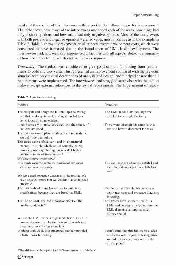
results of the coding of the interviews with respect to the different areas for improvement.The table shows how many of the interviewees mentioned each of the areas, how many hadonly positive opinions, and how many had only negative opinions. Most of the intervieweeswith both positive and negative opinions were, however, mostly positive as in the example inTable 2. Table 3 shows improvements on all aspects except development costs, which wereconsidered to have increased due to the introduction of UML-based development. Theinterviewees had, however, also experienced difficulties with all aspects. Below is a summaryof how and the extent to which each aspect was improved.
Traceability The method was considered to give good support for tracing from require-ments to code and vice versa. This represented an improvement compared with the previoussituation with only textual descriptions of analysis and design, and it helped ensure that allrequirements were implemented. The interviewees had struggled somewhat with the tool tomake it accept external references to the textual requirements. The large amount of legacy
Table 2 Opinions on testing
Positive Negative
The analysis and design models are input to testingand that works quite well, that is, it has led to abetter focus on completeness.
The UML models are too large anddetailed to be used effectively.
It has been easy to make test cases, and the results ofthe tests are good.
There were uncertainties about how totest and how to document the tests.
The test cases were planned already during analysis.We didn’t do that before.
Test cases were defined early and in a structuredmanner. This job, which would normally be big,took only one day. Testing has revealed higherquality in terms of fewer errors.*
We detect more errors now.*It is much easier to write the functional test caseswhen we have use cases.
The use cases are often too detailed andthen the test cases get too detailed aswell.
We have used sequence diagrams in the testing. Wehave detected errors that we wouldn’t have detectedotherwise.
The testers should now know how to write testspecifications because they are based on UML.
I’m not certain that the testers alwaysapply use cases and sequence diagramsin testing.
The use of UML has had a positive effect on thenumber of defects.*
The testers have not been trained inUML and consequently do not use theUML-diagrams as input as muchas they should.
We use the UML models to generate test cases. It isnow a lot easier than before to identify which testcases must be run after an update.
Working with UML in a structured manner provideda better basis for testing.
I don’t think that this has led to a largedifference with respect to testing sincewe did not succeed very well in theearlier phases.
*The different subprojects had different amounts of defects.
Empir Software Eng

code, of which large parts were not reverse engineered, means that not all the code in theproduct can be traced back to the requirements.
Design of the code The use of the ABB UMLmethod dictated a greater focus on design thanhad been the case previously. The interviewees thought that people had come to realize theimportance of designing before coding, which realization had resulted in an improved design.Previously, a prototype would often evolve into code, while now the development is moretop–down, and a design framework is available before coding starts. In particular, theinterviewees considered that the use of sequence diagrams forced them to design thoroughly.Some found, however, that there was not sufficient support in the method for combining top–down and bottom–up development, something which was necessary when many buildingblocks were already available in the form of hardware components or legacy code.
Documentation This project was better documented, both in terms of quantity and quality,than previous software development projects in ABB. The documents now had a moreunified structured with respect to content, and the interviewees found it easier to read thembecause of the common structure. The interviewees thought that more software developerscan learn UML than learn to express themselves well in English. In addition, several of theinterviewees emphasized that the developers found it more fun to make diagrams than towrite textual documentation; hence, they produced more a comprehensive set of analysisand design documents. The interviewees found use cases and sequence diagrams to beparticularly useful. They had, however, experienced difficulties with the format of thedocuments due to problems with the templates, such as which parts of the UML modelswere automatically inserted into the documents and the numbering of the sections in thedocuments. The documents were also often very large because the project members found itdifficult to know how much context they should include in their models in order to describetheir own part. Some documents, for example, contained several hundred pages describingonly one piece of functionality. Some interviewees from sub-projects A and B, the sub-projects which did not generate code from the UML models, thought that they spent toomuch effort on producing documentation during the project that would be outdated whenthe product was finished. Those who generated code automatically also reverse engineeredtheir code to update their models and did not experience this problem.
Testing The development of test cases became quicker and easier when the UML modelswere available, and the coverage of the test cases had improved. On the negative side, thelarge amount of detail in the UML models made them difficult to use as input to testing.Not all the testers had received training in UML, which meant that they could not easilyapply the UML-based test cases, and consequently these were used less often in testing thanthey could have been.
Table 3 Results on possible improvements
Improvement Mentioned by Only positive Only negative
A1: Traceability 10 3 2A2: Communication 9 5 3A3: Design 10 5 2A4: Documentation 16 8 3A5: Testing 11 5 0A6: Costs 12 0 12
Empir Software Eng

Costs There were, of course, costs related to learning a new method. The introduction of anew method also led to much rework. For example, some of the interviewees rewrote thedescription of function several times, due to a revised understanding of the nature of usecases. The amount of detail in the analysis models meant that these sometimes had to beupdated later in the project. The interviewees had also expended a great deal of effort ondiscussing how to best apply UML, both within the teams and in the reviews. In addition,the reviews were considered to have taken more time because the documents wereproduced with a new method. The interviewees found it difficult to estimate how much theintroduction of UML-based development had cost in terms of extra effort, but several ofthem guessed that it had doubled the effort on the project. The interviewees thought,however, that there might be improvements with respect to costs on future projects, whenthey could benefit from the documentation made on this project and the team memberswould be more experienced.
5 Challenges in the Project
The previous section showed that the interviewees had experienced several improvementsto their development process as a consequence of introducing UML-based development,but also that difficulties with using UML, in combination with characteristics of the projectthat were the results of project management decisions, had caused difficulties and thus hadreduced the possible positive effects of introducing such a development method. Thissection describes the difficulties experienced by the interviewees, the project characteristicsthat were considered to cause most problems and how these characteristics affected the useof UML.
5.1 Project Characteristics and their Consequences
The interviewees mentioned four characteristics of the project that contributed to thedifficulties with using UML and that had led to problems with obtaining the desiredimprovements. These characteristics were the consequences of project managementdecisions made because of budget and timing constraints in the project: (1) it wasconsidered too costly to reverse engineer into UML the large amount of legacy code thatthe project had to modify and integrate with, (2) the requirements were distributed to theteams based on physical, and not functional, units of the system, (3) it was consideredtoo costly to provide thorough training for all people involved in the project, (4) thechoice of tools for the modelling process possessed functionality that was not inaccordance with the needs of the project. Table 4 shows how many of the intervieweesdescribed difficulties with the four project attributes. The table also describes theinterviewees who mentioned the characteristics.
5.1.1 Legacy Code
Reverse engineering of the complete existing code base before the start of the project wasconsidered too difficult, and consequently too expensive. The ABB UML method stipulatesthat the parts of the existing code that will integrate with the new code should be reverseengineered into UML models. It also stipulates that interfaces should be identified in thesemodels and that modelling of the new system should use these interfaces, but there is littlesupport on how to actually do this in the method. UML-based development methods mostly
Empir Software Eng

assume development from scratch, and to the authors’ knowledge, there is little meth-odological support for using UML when modifying existing, non-object-oriented systems,even though it is often necessary and also recommended to introduce UML into an existingproduction environment (Selic 2003). The interviewees described the problems related tothe large amount of legacy code that was not reverse engineered, and the consequences ofthese problems. An example of statements about integration with, and modification of,legacy code is given in Table 5. Each row relates the opinion of one interviewee.
Figure 3 shows the interviewees’ opinions about the consequences of having to deal witha large amount of legacy code. Each statement from the interviewees is categorized toclarify the relationships. The main consequences were the following:
& Difficulties with identifying which parts of the architecture implemented which parts ofthe functionality, and how the new requirements related to the existing functionality.This created difficulties when distributing requirements to teams.
Table 4 Opinions on aspects of the project
Project characteristics Mentioned by Comment
Legacy code 6 Mentioned by all people from sub-project A, whichwas the project that had to integrate with legacy code
Org. of req. and teams 5 Mentioned by those with the most experience orinterest in UML-based development
Training and mentoring 10 Mentioned mostly by those who had receivedin-house training and had a positive attitude to the method
Tool 10 Mentioned by interviewees from most of the project
Table 5 Statements related to having legacy code
Statements
Those who had to integrate with legacy code had a much tougher job using this method than had those whodeveloped from scratch, because we have not succeeded in reverse engineering all of the system; forexample, not the parts that were very C-oriented. This means that we often did not have UML interfaces inthe existing code, and it was necessary with so many adaptations in the code to integrate the new parts thatwe felt that we might as well document and test.
The person I worked with implemented new functionality in the existing code and met bigger problems thanI, who developed from scratch, did. He had a new part, modelled in UML. To realize it, the old code had tobe changed almost every second line. Then it was difficult to view the old system as a black box.
We experienced problems because we added to functionality that was not functionally documented, and todesign properly, for example, using a state diagram, you need an existing design that builds on a statediagram. For the most part, the legacy code was not designed in such a way.
The main problem was having existing code that should be modified. It was necessary to know which partsof the old system should be included in the models in order to describe the new part correctly. I believe itwould have been much easier if we had developed from scratch. Reverse engineering resulted in very largedesign documents where only a small part was useful when modelling the new functionality.
We added new functionality to an existing, complex software system that was badly documented. In addition,the templates and guidelines that we used were not adapted to integration with legacy code.
We modelled against a system that was not object-oriented. There were not, for example, always classes orinterfaces in the old code that we could use, so we had to simulate that there were interfaces at the pointswhere we needed them.
Empir Software Eng

& Both developers and reviewers had difficulties with abstracting away from the code inanalysis and design when they knew the existing code well. This contributed to analysisand design models with too much detail.
& Difficulties with identifying clear-cut interfaces to the old code that could be used in thenew models. It was necessary to know the old code well in order to know how much ofit had to be modelled to document the new part well.
& General problems with obtaining benefits with respect to design when applying UMLbecause they had to know, and adapt to, the existing code.
5.1.2 Organization of Requirements and Teams
The distribution of requirements to teams was mostly done before beginning to use theABB UML method. It was done based on physical units, previous experience and onwhich teams had available resources. There were approximately 1,000 requirements forthe new system, but these were not organized hierarchically. The ABB UML methodstates that identical functionality should be identified and separated out as included usecases, but there was no organized activity of identifying similar functionality over severalteams; nor was there any activity on integrating the different models and ensuring unifiedinterfaces. Figure 4 shows the interviewees’ opinions about the consequences of not orga-nizing and distributing requirements to teams based on functionality and not organizing
Integration with legacy code
Reviewers tended to Reviewers tended to Reviewers tended to Reviewers tended to comment more on comment more on comment more on comment more on the models of the the models of the the models of the the models of the legacy code with legacy code with legacy code with legacy code with which they were which they were which they were which they were familiar than on the familiar than on the familiar than on the familiar than on the new codenew codenew codenew code
Unneccesary effort on reviews and corresponding costs
The new product The new product The new product The new product has undocumented has undocumented has undocumented has undocumented legacy codelegacy codelegacy codelegacy code
Reduces effect of UML on documentation
The high-level The high-level The high-level The high-level sequence diagrams sequence diagrams sequence diagrams sequence diagrams contained procedure contained procedure contained procedure contained procedure calls to fit the calls to fit the calls to fit the calls to fit the description of the description of the description of the description of the legacy codelegacy codelegacy codelegacy code
Contributed to too much detail in UML models
It was difficult to It was difficult to It was difficult to It was difficult to map new map new map new map new functionality onto an functionality onto an functionality onto an functionality onto an existing existing existing existing architecture that architecture that architecture that architecture that was not documented was not documented was not documented was not documented with UMLwith UMLwith UMLwith UML
Contributed to problems with interfaces between models
Interfaces between Interfaces between Interfaces between Interfaces between new and old parts of new and old parts of new and old parts of new and old parts of the system were the system were the system were the system were often missingoften missingoften missingoften missing Problems with interfaces
It was difficult to It was difficult to It was difficult to It was difficult to identify interfaces in identify interfaces in identify interfaces in identify interfaces in the old codethe old codethe old codethe old codeProblems with interfaces
There were design There were design There were design There were design classes in the old classes in the old classes in the old classes in the old code, so it felt code, so it felt code, so it felt code, so it felt superfluous to make superfluous to make superfluous to make superfluous to make analysis classes for analysis classes for analysis classes for analysis classes for the same conceptsthe same conceptsthe same conceptsthe same concepts
Contributed to problems with level of detail in the UML models
It was difficult to It was difficult to It was difficult to It was difficult to know which parts of know which parts of know which parts of know which parts of the legacy code to the legacy code to the legacy code to the legacy code to model and include in model and include in model and include in model and include in the new models to the new models to the new models to the new models to well describe a new well describe a new well describe a new well describe a new partpartpartpart
Reduces effect of UML documentation
Models that Models that Models that Models that included reverse included reverse included reverse included reverse engineered parts of engineered parts of engineered parts of engineered parts of the old system got the old system got the old system got the old system got very largevery largevery largevery large
Reduces effect of UML documentation
It was difficult to It was difficult to It was difficult to It was difficult to abstract away from abstract away from abstract away from abstract away from code that was code that was code that was code that was already therealready therealready therealready there
Contributed to too much detail in the UML models
It was easy to It was easy to It was easy to It was easy to start thinking start thinking start thinking start thinking design too early design too early design too early design too early when there was an when there was an when there was an when there was an existing code existing code existing code existing code basebasebasebase
Contributed to too much detail in the UML models and to problems with choice of diagrams
It was difficult to It was difficult to It was difficult to It was difficult to make a good design make a good design make a good design make a good design when modifying when modifying when modifying when modifying legacy code not legacy code not legacy code not legacy code not designed according designed according designed according designed according to such principles to such principles to such principles to such principles
Reduces effect of UML as a means to obtain improvements in design of code
Fig. 3 Consequences of modifying legacy code
Empir Software Eng

cooperation among teams that were developing functionality that interacted with thefunctionality being developed by other teams. The main consequences were the following:
& The focus was often on physical components as such and not on functionality.& Related functionality was not always distributed to the same team, meaning that it was
often difficult to map requirements to use cases.& One analysis model did not necessarily correspond to a logical part of the system.
Hence, it was difficult to integrate different models, and in some cases there wasoverlapping functionality in different models.
5.1.3 Training and Mentoring
Most of the developers were novices at modelling with UML when starting to work onthis project. Otherwise, they were well-qualified developers (most holding the equivalentof an MSc degree) and with several years experience at ABB. They were familiar withboth the V-model and Gate model. At the start of the project, they attended courses oftwo to five days that covered UML syntax, Rational Rose tools and the ABB UMLmethod. A special team, the UML team, was set up to help the rest of the project withthe use of UML, which included responsibility for developing templates and forreviewing documents, with particular focus on the correct use of UML. The number ofpeople in the UML team varied from three to five over the course of the project.
The interviewees reported that there had been too little training because managers,reviewers and testers, who did not themselves develop, did not receive training eventhough they had to read and understand the models. Some of them also had roles thatrequired them to motivate and teach others to use UML correctly. Developers who startedon the project after the courses did not receive the same training as the others.
There were also problems reported with the training they received. The intervieweessaid that the courses focused too much on UML syntax and too little on the ABB UMLmethod and semantics of diagrams and constructs. There were not enough practicalexercises on using the tools and it was not made clear what should actually be achievedby modelling. It was considered necessary, but not sufficient, to master the syntax in
Distribution of requirements
to teams
Badly structured models, in particular use case models
Reduces effect of UML documentation
Individual models that were difficult to integrate
Contributed to problems with interfaces
Difficulties with getting a complete overview of (parts of) the system
Reduces effect of UML documentation
Difficulties with the relationship between requirements and use cases
Contributed to some problems with traceability
Focus on realizing complete components too early when focus should be on functionality
Contributed to problems with level of detail
It was difficult to know which other teams to integrate with
Contributed to problems with interfaces
It was often difficult to see where each use case fits in
Reduces effect of UML documentation
It was difficult to understand and realize requirements in isolation
Contributed to additional costs
Overlapping functionality in different analysis models
Reduces effects of UML as a means to improve design of code
Analysis models that did not correspond to a logical part of the system
Reduces effect of UML documentation
Fig. 4 Consequences of unsystematic distribution of requirements to teams
Empir Software Eng

order to apply UML successfully. The courses were developed for the project, but notadapted to the specific context.
The interviewees believed that the UML team was not sufficiently qualified, and didnot have sufficient authority, to guide the total use of UML in the project because theylacked the necessary experience with both development and UML. At the beginning ofthe project there were some senior developers in the team, but these were considered tooimportant for the rest of the project to be given time to spend on the UML team. Themembers of the UML team did not receive additional training in UML-based development.
Figure 5 shows the interviewees’ opinions on the consequences of these problems. Themain consequences were these:
& It was not well understood how to apply the concepts of actors and use cases in thecontext of embedded development.
& There were large differences in how the different teams applied UML and themethod.
& Those who had attended courses often expected to be able to use the course materialdirectly in the development, but this caused difficulties since the material was notadapted to the project context.
& The templates that were used in the project were not sufficiently adapted to the projectcontext.
& The project members did not always use UML-models when they could have usedthem. UML-models were, for example, not always applied as input to making testcases.
5.1.4 Tools Used in Modelling and Documenting
Some of the interviewees believed that Rational Rose lacked stability, but they were mostlysatisfied with its functionality. Rational Rose SoDA was used to produce documents
Training and mentoring
Different opinions on Different opinions on Different opinions on Different opinions on use of UML from use of UML from use of UML from use of UML from different reviewersdifferent reviewersdifferent reviewersdifferent reviewers
Contributed to higher costs
Reviewers were Reviewers were Reviewers were Reviewers were unable to determine unable to determine unable to determine unable to determine when particular when particular when particular when particular diagrams were diagrams were diagrams were diagrams were useful, in particular useful, in particular useful, in particular useful, in particular with respect to with respect to with respect to with respect to number of sequence number of sequence number of sequence number of sequence diagramsdiagramsdiagramsdiagrams
Contributed to problems with level of detail and choice of diagram
Large differences Large differences Large differences Large differences with respect to how with respect to how with respect to how with respect to how the teams used UMLthe teams used UMLthe teams used UMLthe teams used UML
Contributed to problems with level of detail and interfaces
Uncertainties with Uncertainties with Uncertainties with Uncertainties with respect to how to respect to how to respect to how to respect to how to apply models in apply models in apply models in apply models in testingtestingtestingtesting
Reduced the effect of having UML models as a basis for testing
Testers didn't Testers didn't Testers didn't Testers didn't always use the always use the always use the always use the models in the models in the models in the models in the testingtestingtestingtesting
Reduced effect of having UML models as a basis for testing
Reviewers spent too Reviewers spent too Reviewers spent too Reviewers spent too much time on UML much time on UML much time on UML much time on UML detailsdetailsdetailsdetails
Contributed to higher costs
Much rewriting of Much rewriting of Much rewriting of Much rewriting of modelsmodelsmodelsmodels
Contributed to higher costs
Templates that were Templates that were Templates that were Templates that were not sufficiently not sufficiently not sufficiently not sufficiently adapted to the adapted to the adapted to the adapted to the projectprojectprojectproject
Contributed to higher costs
Insufficient Insufficient Insufficient Insufficient motivation for using motivation for using motivation for using motivation for using the methodthe methodthe methodthe method
Contributed to there being smaller/fewer perceived improvements
Difficulties with Difficulties with Difficulties with Difficulties with respect to which respect to which respect to which respect to which diagram to applydiagram to applydiagram to applydiagram to apply
Contributed with problems with respect to choice of diagram
Much time on Much time on Much time on Much time on understanding UML understanding UML understanding UML understanding UML concepts, in concepts, in concepts, in concepts, in particular the use particular the use particular the use particular the use case conceptcase conceptcase conceptcase concept
Contributed to higher costs
Fig. 5 Consequences of insufficient training and mentoring
Empir Software Eng

automatically from the models in Rational Rose; that is, the models were inserted intopredefined Word-templates. The interviewees reported that it was difficult to createdocuments with an acceptable layout when the models were inserted into documentsautomatically. For example, the developers were unable to set the text fonts in theUML-models in Rational Rose, and they did not succeed in controlling the numberingof the sections in the documents. Therefore, they had to make quite a lot of changes tothe automatically generated documents, and consequently it was costly to make changesin the models because this implied generating new documents.
In addition, the interviewees thought that Rational Rose may also have contributedsomewhat to the low level of detail in the high-level sequence diagrams because RationalRose facilitates in the sequence diagrams, the use of classes and methods that have alreadybeen defined in class diagrams.
5.2 Difficulties with Using UML
The previous section described project decisions that caused problems with applyingUML and thus reduced the effect of introducing UML-based development. The inter-viewees mentioned three main difficulties with applying UML: (1) the choice of diagramto use in a specific situation, (2) the interfaces between models, and (3) the level of detailin the models. Table 6 shows how many of the interviewees mentioned problems with eachof the aspects.
5.2.1 Choice of Diagrams
Some interviewees reported problems with the choice of diagram to apply. They foundthat there was too much focus on use cases and sequence diagrams in the ABB UMLmethod, and thought that activity diagrams could be more useful early in analysis whenfew actual objects have been identified. More use of activity diagrams could havecontributed to deterring the focus on detailed classes. The interviewees had, however,focused on making the UML models that were compulsory in the ABB UML method,since they did not feel that they had a good enough grasp of the goal of applying eachof the models to choose when to apply which. The lack of insight into exactly whateach model should express also meant that the interviewees found it difficult to knowwhen it was necessary to supplement the models with text and when the models wereself-contained.
5.2.2 Interfaces
The interviewees had experienced large problems with interfaces between modelsdescribing different, but interacting, parts of the system. Well-described interfaces were
Table 6 Results on difficultieswith UML UML aspect Mentioned by
Choice of diagram 6Interfaces 10Level of detail 10
Empir Software Eng

considered vital for understanding where each part fits in and to get an overview of thesystem, but most of the interviewees found that the interfaces were either missing ortoo detailed.
High-level interfaces were in the form of actors. In addition to actors that wereexternal to the whole system, such as operators and hardware devices, the ABB UMLstipulates that subsystems should be considered as actors for each other. Thesesubsystems could be legacy code or other subsystems being developed in parallel. Anactor mostly interacts with a subsystem in several places. In the modelling process, suchlow-level interfaces were marked with the symbol ○. Such interfaces were graduallysubstituted with actual function calls when these were established. The interviewees hadexperienced several problems:
& For interfaces in the form of actors that were not human users it was more difficult toidentify them and how they would interact with the system than for those actors thatrepresented human users.
& Interfaces in the legacy code posed difficulties because the legacy code was onlypartially reverse engineered into UML models. Consequently, there were often fewinterfaces in the old code that could be used directly.
& Interfaces in subsystems that were developed in parallel also posed problems. TheABB UML method stipulates that the people responsible for the different subsystemsshould communicate about the exact nature of the interface. However, this was oftendifficult because the different subsystems were developed according to differentschedules and some subsystems were developed mostly bottom–up, based on existingcomponents, while others were developed top–down. The interviewees also reportedthat they did not have a good grasp of how to group use cases into subsystems,something that also contributed to the interfaces between the subsystems not beingclear-cut.
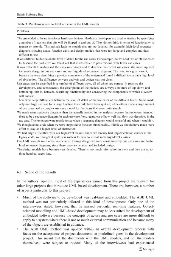
5.2.3 Level of Detail
Examples of statements about level of detail in the models are given in Table 7. Each rowrelates the opinion of one interviewee. The main problems were these:
& The teams had started to think about code when the focus should have been onfunctionality. Both the use cases and the high-level sequence diagrams wereconsidered to be too detailed, because they often included the same functions asthe code.
& It was difficult to decide how to divide functionality into use cases and to decide howmany sequence diagrams should be made for each use case.
& The distinction between analysis and design was not clear. The analysis modelsincluded design details and were consequently often difficult to use in the design,because they constrained the design models.
6 Scope and Validity of the Results
This section describes the scope and validity of the case study reported in this paper.
Empir Software Eng
6.1 Scope of the Results
In the authors’ opinion, most of the experiences gained from this project are relevant forother large projects that introduce UML-based development. There are, however, a numberof aspects particular to this project.
& Much of the software to be developed was real-time and embedded. The ABB UMLmethod was not particularly tailored to this kind of development. Only one of theinterviewees stated, however, that he missed particular real-time features. Object-oriented modelling and UML-based development may be less suited for development ofembedded software because the concepts of actors and use cases are more difficult toapply to a system where there is not so much external communication and because manyof the objects are established in advance.
& The ABB UML method was applied within an overall development process withfocus on the acceptance of project documents at predefined gates in the developmentproject. This meant that the documents with the UML models, and not the modelsthemselves, were subject to review. Many of the interviewees had experienced
Table 7 Problems related to level of detail in the UML models
Problems
The embedded software interfaces hardware devices. Hardware developers are used to starting by specifyinga number of registers that bits will be flipped in and out of. They do not think in terms of functionality torequest or provide. This attitude leads to models that are too detailed; for example, high-level sequencediagrams showing actual function calls, and design models that were too large and complex and thusdifficult to use.
It was difficult to decide on the level of detail for the use cases. For example, do we need two or 20 use casesto describe the problem? We found out that it was easier to pass reviews with fewer use cases.
It was difficult to understand the use case concept and to describe the correct use cases. We ended up withtoo much design in our use cases and our high-level sequence diagrams. This was, to a great extent,because we were describing a physical component of the system and found it difficult to start at a high levelof abstraction. The difference between analysis and design was not clear.
Use cases can be described in a number of different ways, all of which are correct. In practice thedevelopment, and consequently the descriptions of the models, are always a mixture of top–down andbottom–up; that is, between describing functionality and considering the components of which a systemwill consist.
There were large differences between the level of detail of the use cases of the different teams. Some madeonly one large use case for a large function that could have been split up, while others made a large amountof use cases and a complex use case model for functions that were quite simple.
We made more sequence diagrams than we actually needed in the analysis because the reviewers intendedthere to be a sequence diagram for each use case flow, regardless of how well that flow was described in theuse case. The reviewers were unable to see when a sequence diagram would be useful and when it wouldn’t.
We thought about code when we were supposed to focus on functionality. I think we should have made moreeffort to stay at a higher level of abstraction.
We had large difficulties with our high-level classes. Since we already had implementation classes in thelegacy code, we thought it quite was useless to have to invent some high-level classes.
Our UML models were often too detailed. During design we were constrained by our use cases and high-level sequence diagrams, since these were so detailed and included design.
The design models have become very detailed. There is too much information in them and they are up tothree hundred pages long.
Empir Software Eng

difficulties with the format of these documents, and that may have overshadowedtheir opinions on UML-based development as such.
& The requirements were well-defined before the application of the ABB UML method.The safety requirements were derived from IEC 61508. Most of the functionalrequirements were the result of the system’s relations to hardware artifacts, whilesome of them were responses to the needs of users of the system, such as processoperators and engineers. This meant that the functional requirements were mostlyindependent of users’ needs and abilities to define requirements. Use cases areclaimed to be particularly useful for eliciting and elaborating functional requirements,but such activities were not part of this project, and use case modelling may,therefore, have been considered less useful than it would have been if such activitieshad been included.
& The use cases were constructed solely by developers who were also domain experts.ABB develops products for sale, and consequently there were no clients involved inthe development process. This probably contributed to the low level of detail in theuse case models.
& The teams had worked in a very vertical way, mostly with one team beingresponsible for analysis, design and coding. The benefits of analysis and design withUML may have been greater if the analysis and/or design models had been handedover to other teams for further elaboration. In addition, in practice, not all steps ofthe ABB UML method were necessarily followed by all teams. Absoluteconformance to a development method is, however, seldom observed in softwaredevelopment projects (Fitzgerald 1997), and in this case the safety constraints forcedthe developers to produce all the UML-models stipulated by the ABB UML method.
ABB chose UML-based development because of good tool support. We believe thatthe project would have experienced many of the same improvements and challenges ifthey had chosen another modelling language and method as a basis for their improvementinitiative. However, we do believe that there are some matters that are particular to UML-based development. The use of use case diagrams may lead to a focus on the overallsystem rather than on the individual parts. The packages in Rational Rose may also havecontributed to an awareness of each team working on a part of a larger system. In thiscase, the system to be constructed was too large and complex to easily provide an overallpicture of its functionality. Many of the difficulties reported in the interviews were relatedto problems with describing models and their interfaces in such a way that they couldprovide an overview of the system. These difficulties may have been lessened if amethod for analysis and design had been used that had less focus on overall functionalityand more on detailed design.
6.2 Validity of the Results
The results of this study are based on interviews with the project participants, and ourmeasures are their perceived improvements and problems. The interviewees were selectedto represent different parts of the project and they all had experience with using UML onthe project. The people present at the interviews (the first and fourth author) were notemployed by ABB, and the interviewees were guaranteed anonymity. Our impression isthat the interviewees spoke freely. The conduct of interviews and confidentiality issues arediscussed further in Hove and Anda (2005) which is, among others, based on theexperiences from these interviews.
Empir Software Eng

With respect to validity of results based on interviews there are, in particular, two aspectsof validity to consider (Maxwell 1992):
& Descriptive validity; that is, whether the interviewees’ opinions are rendered correctly.In this case, the interviews were transcribed, based on tapes, by the research assistantwho had been present at, but not directly involved in, the interviewing. The analysiswas based on these transcribes.
& Interpretive validity; that is, whether the interviews are correctly interpreted. In thiscase, the interviewees spoke very informally, and ten of the interviewees wereSwedish. Consequently, it was necessary to translate and rewrite the transcriptionssomewhat before the coding of the interviews. It is possible that the meaning ofsome individual sentences may have been altered slightly in this process. Thecategories used in the analysis are the result of several iterations on coding theinterviews, and previous iterations also included other categories for coding thatwere discarded because very few sentences in the interviews were coded accordingto them. These categories were requirements analysis, the method description andthe syntax of UML in relation to improvements, project decisions and difficultieswith UML, respectively. Three project members, who had not been interviewed, alsoread through and verified a draft of this paper.
There are few empirical studies on UML-based development with which to compareour results. Nevertheless, some of our results are supported by the results reported in apaper with lessons learned from developing embedded software (Pettit 2004). That paperalso reports improved communication due to the introduction of UML-based development,as well as challenges with respect to describing interfaces between UML models. Ourresults are also supported by the results from a study on the introduction of object-oriented development (Malan et al. 1995). The experiences reported in that paper alsoemphasize the need for sufficient training, reverse engineering of legacy code, and adequatedistribution of subsystems to teams, as well as the economic challenges involved in theseactivities. Furthermore, some of our results are supported by the results from a study onthe usability of UML diagrams (Agarwal and Sinha 2003). That study also revealeddifficulties with understanding the concept of use cases and describing them withappropriate detail, as well as with modelling interface objects in class diagrams. Difficultieswith level of detail in use case models have been mentioned, for example in (Armour andMiller 2000; Cockburn 2000; Kulak and Guiney 2000).
7 Conclusions and Future Work
This paper reports the results of a case study on adopting UML and an associated UML-based development method in a large, international development project in ABB. Data wascollected through interviews with 16 developers and managers. Principles from groundedtheory were used in the analysis of the interviews.
The interviewees had obtained several immediate improvements as a consequence ofintroducing a UML-based development method. These were improved traceability ofrequirements to code, improved communication within the development teams (and tosome extent in the reviews), improved design of the code, quicker development of testcases and better coverage of these, and a product that was better documented than wereprevious products. The interviewees also stated that there had been difficulties related to
Empir Software Eng

obtaining these improvements and also that development costs had increased due to theadoption of UML. When applying UML, the interviewees had experienced difficultieswith choosing an appropriate diagram in a specific situation, interfaces between differentmodels, and with the level of detail in the models. There were four decisions made at thestart of the project that the interviewees identified as having caused problems with theuse of UML. These were related to lack of reverse engineering of legacy code, un-systematic distribution of requirements to teams, insufficient training and mentoring, andchoice of modelling tools.
Despite the widespread use of UML in industry, there has been little evaluation of UML-based development in industrial projects. In the authors’ opinion, this study thus representsa contribution to the body of knowledge regarding benefits and challenges involved inadopting UML-based development that should provide valuable input to the developmentof a theory in the field as well as to practitioners. The ABB UML method has also beenchanged, partly based on the results from this study.
The following activities are in progress, or are planned, in order to further evaluate theuse of UML-based development in ABB. First, a questionnaire, with questions based on theresults of the interviews, has been distributed to the participants in the project to investigatespecific aspects of the development process in more detail. Second, project documents fromthe project, in the form of UML-documents, review reports and test reports are beinganalyzed, to identify what changes were made to the analysis models and what caused thesechanges to be made. Third, more case studies on the adoption, adaptation and use of UML-based development in various types of projects are needed to better understand how suchdevelopment should be applied to improve software development processes.
Acknowledgments We acknowledge all the employees of ABB in Sweden and Norway who participatedin the interviews and their managers. We thank Lionel Briand for valuable comments on the case study,and we also thank Hans Christian Benestad, Vigdis By, Dag Sjøberg, Marek Vokác, Ray Welland, ChrisWright and the anonymous reviewers for their comments on a previous version of the paper. The reportedwork was funded by The Research Council of Norway through the industry project SPIKE (SoftwareProcess Improvement based on Knowledge and Experience).
Appendix A. Brief Description of the ABB UML Method
The requirements analysis phase of the ABB UML method:
R1. Identify actors and use cases, and document themActors are the system’s external interfaces. Humans, timers, sensors, or anything elsethat interacts with the system, can be an actor. For a use case diagram in a subsystem,other (interacting) subsystems should also be defined as actors.Use cases:
& Define the system as seen from the actors’ point of view.& Represent the different usage of the system and system services.& Capture the requirements.
A use case is always initiated by an actor.
Empir Software Eng

R2. Group use cases and actors into subsystemsThere should be strong cohesion within the subsystems and a weak coupling betweenthe subsystems.
R3. Refine the use cases and identify dependenciesIf some use cases show common behaviour at specific points, and this commonality can beextracted without disturbing the main functionality, it can be factored out as a separate usecase and included in the diagrams from which they were extracted using the <<include>>stereotype. If some use cases have behaviour that can be seen as additions to, or variationsof, normal behaviour, such forms of behaviour can be factored out as separate use casesand included in the use cases from which they were extracted using the <<extend>>stereotype. The different possible extension points are listed inside the lower half of theuse case, and each <<extend>> is marked with the connecting extension point.
The analysis phase of the ABB UML method:
A1. Describe flow of events inside the use case (textual)Describe each use case with the normal flows of events inside the use cases (each usecase has at least one normal flow of events). Then capture the exceptional flows ofevents for each use case. This is done in several iterations.
A2. Create high-level sequence diagramsHigh-level sequence diagrams should be used to show the dynamics between the objectsinvolved in the use case and the actors interfacing them, for both normal and exceptionalflows of events. Objects of type inclusionPoint with the names of the included use cases,and objects of type extensionPoint with the <<extend>> names take the included andextended sequence diagrams’ roles. Only objects with ‘focus of control’ or actors mayinitiate messages. A base use case transfers ‘focus of control’ to the object to which itsends a synchronous message, but it keeps the ‘focus of control’ if the message isasynchronous. An object that receives a message gains “focus of control.” Informationcontained in objects must be placed there by another object before it can be extracted,and it originates in an actor outside the system.
A3. Define interfaces between use cases in different subsystemsThere are interfaces between the subsystems. In the use case diagrams there aredependency arrows from the use cases to their interfaces. The exact messages includedin the interfaces are identified by those responsible for the subsystems that interact.
A4. Describe the activities in the use case in an activity diagram (Optional)Activity diagrams should show the different activity states of the use case, for bothnormal and exceptional flows of events.
A5. Create high-level class diagramsIdentify high-level classes. A high-level class describes the commonality betweensimilar objects in the sequence diagrams and defines the structure and behaviour for eachobject in the class. Assign objects to the correct classes. The interactions between theobjects in the sequence diagrams help to identify the operations in the classes. The dif-ferent messages will identify operations in the class of the receiving object. Find theinformation contents necessary to process each message in the sequence diagrams.This information will end up as attributes in the class of the receiving object.The high-level class-diagram should show associations between the classes.
A6. Update sequence diagrams with correct high level class and operation namesWhen high-level class diagrams are made, the mapping back to the sequence diagrams mustbe done. Mark out in which technology the high-level class would be implemented (SW,VHDL, HW). These distinctions will be used when we start to build the component view.
Empir Software Eng

The Detailed Design phase of the ABB UML Method (Note that the hardwaredevelopers did no detailed design):
Detail design (SW)The goal of this phase is to realize the high-level classes with implementation class
diagrams and to group the classes in components. The detailed class diagrams includerelations between classes, operations and attributes. State transition diagrams may be usedin the process of elaborating the class diagrams.
The detailed classes are connected to the high-level classes through a “realize” association.In this context, it makes sense to expose operation signature details for the high level classes.
The classes with strong coupling are typically candidates for a component, as are classeswith the same implementation technology. When classes with strong coupling but differentimplementation technology are distributed to different components, an interface must bemade to take care of the classes.
Appendix B. Interview Guide
1. What is your professional background?2. Can you describe your role in the project?3. How well did you know UML and UML-based development at the start of this project?4. What were your expectations when starting to use UML and the ABB UML method;
what benefits and costs did you expect?5. Have you previously worked on similar projects, with or without UML, so that you
can compare experiences from that project with this one?6. What are your opinions about the training you received?7. With whom did you cooperate on the use of UML?8. Did you have to adapt the ABB UML method in any way to the needs of the part of
the system that you were modelling?9. What is your experience with the different diagrams, use cases, sequence diagrams,
class diagrams etc.?10. Were there parts of the systems that you had problems modelling using UML?11. How did you find the reviews?12. Who are the receivers of the UML-models that you produce, apart from the reviewers?13. What kinds of interface did your code have to other UML models or to existing code
and how do you think you succeeded in modelling those interfaces?14. What were, in your opinion, the costs involved in applying UML and the ABB UML
method and what were the benefits?15. Do you have any experience with maintenance of systems that are documented using
UML?16. Is there anything that you would have done differently if you could start all over again?17. Howwould you rate the ease of comprehension of the UMLmodels that you have read?18. Do you believe that you can identify good use of UML; do you have any specific criteria?
Appendix C. Categories for Coding of the Interviews
Background:ExpectationsExperience
Empir Software Eng

Training (which)Activities (in the project)
Possible improvements:TraceabilityCommunication, ReviewsDesignDocumentationTest, DefectsCosts
Project characteristics:Training, Mentoring (opinions)UML teamLegacy codeOrganization (of requirements and teams)Tools, Templates
Use of UML:InterfacesLevel of detail, Abstraction levelChoice of diagrams
References
ABB (2001) Gate model for product development 1.1 Tech. report 9AAD102113, ABB/GP–PMI, Västerås,Sweden
Agarwal R, Sinha AP (2003, September) Object-oriented modeling with UML: a study of developers’perceptions. Commun ACM 46(9):248–256
Armour F, Miller G (2000) Advanced use case modelling. Addison-WesleyBooch G, Rumbaugh J, Jacobson I (1998) The unified modeling language user guide. Addison-WesleyCockburn A (2000) Writing effective use cases. Addison-WesleyCox K, Phalp K (2000) Replicating the CREWS use case authoring guidelines experiment. Empiri Software
Eng 5(3):245–267Douglass BP (2004) Real time UML: advances in the UML for real-time systems. 3rd edn. Addison-Wesley,
Boston, MassachusettsEisenhardt KM (1989) Building theories from case study research. Acad Manage Rev 14(4):532–550Fitzgerald B (1997) The use of systems development methodologies in practice: a field study. Inf Syst J
7:201–212Fowler M (2003) UML distilled. A brief guide to the standard object modelling language, 3rd edn. Addison-
WesleyHansen KT, Gullesen I (2002) Utilizing UML and patterns for safety critical systems. In: Jürjens et al. (eds)
Critical systems development with UML, number TUM-I 0208 in TUM technical report, UML’02satellite workshop proceedings
Hove SE, Anda B (2005) Experiences from conducting semi-structured interviews in empirical softwareengineering research. Accepted for presentation at metrics
Huberman AM, Miles MB (2002) The qualitative researcher’s companion. SAGE Publications, Inc.,Thousand Oaks, California
IEC (1998) 61508: Functional safety of electrical/electronic/programmable electronic safety-related systems.(http://www.iec.ch/)
Kulak D, Guiney E (2000) Use cases: requirements in context. Addison-WesleyMalan R, Coleman D, Letsinger R (1995) Lessons from the experiences of leading-edge object technology
projects in Hewlett–Packard. Proceedings OOPSLA 1995, pp 33–46Maxwell JA (1992) Understanding and validity in qualitative research. Harv Educ Rev 62(3):279–300
Empir Software Eng

Otero MC, Dolado JJ (2002) An initial experimental assessment of the dynamic modelling in UML. EmpiriSoftware Eng 7(1):27–47
Peleg M, Dori D (2000) The model multiplicity problem: experimenting with real-time specificationmethods. IEEE Trans Softw Eng 26(8):742–759
Pettit RG (2004, May 11–12) Lessons learned applying UML in embedded software systems designs.Proceedings of the second IEEE workshop on software technologies for future embedded and ubiquitoussystems (WSTFEUS’04), Vienna, Austria pp 75–79
Seaman CB (1999, July/August) Qualitative methods in empirical studies in software engineering. IEEETrans Softw Eng 25(4):557–572
Selic B (2003, September/October) The pragmatics of model-driven development. IEEE Softw 20(5):19–25Sjøberg DIK et al (2005) A Survey of Controlled Experiments in Software Engineering. To appear in IEEE
Trans Softw EngStrauss A, Corbin J (1998) Basics of qualitative research: techniques and procedures for developing
grounded theory. 2nd edn. SAGE Publications, Inc., Thousand Oaks, CaliforniaThe ABB Instruction “Software and Hardware development,” 2001The ABB Guideline “Guideline for use of semi-formal methods in Software and Hardware design,” 2003Yin R (2003) Case study research: design and methods. 3rd edn. SAGE Publications, Inc., Thousand Oaks,
CaliforniaZendler A et al (2001) Experimental comparison of coarse-grained concepts in UML, OML and TOS. J Syst
Softw 56(4):21–30
Bente Anda received a PhD in informatics in 2003 from the University of Oslo. She now works as researchscientist at Simula Research Laboratory and as associate professor in the Department of Informatics,University of Oslo. She has previously worked three years as lecturer at The Norwegian School ofInformation Technology (NITH) and four years as consultant and project manager in IBM. Her researchinterests include model-driven development, empirical software engineering and software processimprovement.
Kai Hansen is a senior principal scientist at ABB Corporate Research in Norway. His research interestsinclude software engineering, safety certified systems, industrial communication and embedded systemdesign. He has a Ph.D. in theoretical physics from the University of Oslo and has worked at universities inDenmark and Germany. He is a senior member of the IEEE and is a certified project manager by PMI.
Empir Software Eng
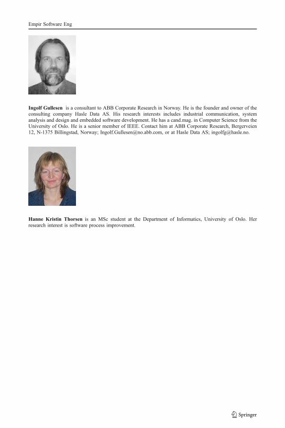
Ingolf Gullesen is a consultant to ABB Corporate Research in Norway. He is the founder and owner of theconsulting company Hasle Data AS. His research interests includes industrial communication, systemanalysis and design and embedded software development. He has a cand.mag. in Computer Science from theUniversity of Oslo. He is a senior member of IEEE. Contact him at ABB Corporate Research, Bergerveien12, N-1375 Billingstad, Norway; [email protected], or at Hasle Data AS; [email protected].
Hanne Kristin Thorsen is an MSc student at the Department of Informatics, University of Oslo. Herresearch interest is software process improvement.
Empir Software Eng