experiences with traceability of molbloc …inm.ro/pdf/2009-03-trasabilitatea.pdf · experiences...
TRANSCRIPT

T E H N I C A M Ă S U R Ă R I I
38 METROLOGIE 1/2009 (p. 38-43)
EXPERIENCES WITH TRACEABILITY OF MOLBLOC FLOWMETERS TO PRIMARY GRAVIMETRIC MASS
FLOW STANDARD
Zdeněk KRAJÍČEK, Dominik PRAŽÁK, Tomáš HAJDUK, Jiří TESAŘ*
*CZECH METROLOGY INSTITUTE, CEHIA
Rezumat. Scopul acestei lucrări este acela de a evalua în detaliu sistemul secundar molbox – molbold de etalonare a debitului, din punctual de vedere al influenţei presiunii de linie asupra măsurării debitului. Acesta este un răspuns la creşterea cerinţelor cumpărătorilor (în special din domeniul automobilelor şi semiconductorilor industriali) de a avea debitmetrele etalonate la diferite presiuni de linie. În lucrare se arată faptul că, fiecare sensor molbloc este, în principal, unic în sensibilitatea sa datorată schimbărilor presiunii de linie. Cuvinte cheie: debitmetru molbloc, etalon, comparaţie, sensor, presiune de linie. Abstract. The aim of this paper is to evaluate in detail the secondary flow-calibration system molbox–molbloc from the point of view of the influence of the line pressure on the indicated flow. This is a response to the increasing demands of the customers (mainly from automobile and semiconductor industries) to have their flowmeters calibrated at various line pressures. It shows that every molbloc sensor is in principal unique in its sensitivity to the changes of the line pressure. Key words: molbloc flowmeter, standard, comparison, sensor, line pressure.
1. INTRODUCTION
Many volume flowmeters are very sensitive to line pressure and the corrections used for the influence of the change of line pressure are not accurate enough. So the customers that need lower calibration uncertainties than can be reached by traditional correction conventions wish to have their instruments calibrated at their working line pressures. These line pressures vary from the pressures lower than atmospheric to 600 kPa absolute. The team of the authors uses a secondary standard molbox–molbloc traceable to a primary gravimetric standard to perform every day calibrations. The molbloc flowmeters are set and calibrated by the manu-facturer at line pressure 280 kPa absolute. The manufacturer does not provide these instruments with calibrations at other line pressures, but the differences can (depending on flow and line pres-sure values) be up to 0.5 % of the measured value which is too much for instruments with uncertainty down to 0.2 % of the measured value. What is also important, the authors’ laboratory needs a high accuracy molbox–molbloc for precise regulation of gas flow from the gravimetric apparatus.
2. THE PRIMARY STANDARD GFS
The gravimetric flow system (GFS) manufactured by DH-Instruments [1,2] serves as the primary low gas flow standard. It determines the mass flow
from the decrease of the mass of a pressure bottle placed on an accurate electronic balance with a resolution of 0.1 mg, an automatic zeroing and calibration system, and automatic handling of the pressure bottle. This entire system is enclosed in a box ensuring the elimination of the influence of air flow on mass indication which is also equipped with the system monitoring pressure, temperature and humidity of air surrounding the bottle and balance. Everything is placed on a vibration absorbing table. The pressure bottle is equipped with two pressure regulators ensuring a constant pressure in a capillary connecting the pressure bottle with the flow regulator and the device under test. The capillary is of catenary shape to ensure minimal effect of mass indication by its elastic forces. After leaving the capillary the flow enters a temperature stabilization volume and then a mass flow controller (MFC) ensuring the stability of the flow. The MFC maintains the desired flow rate set via a flowmeter control unit. After passing through the molbloc unit, which measures and integrates the flow via its control terminal molbox, the gas leaves into the atmosphere (or it can be pumped using the Busch Seco SV1025 vacuum pump).
The working range of this calibration system is from 0.2 to 200 mg/s, i.e. from 10 to 10 000 sccm, i.e. standard cm3 per minute, for nitrogen. This is the specification of the manufacturer, but our team managed to prove that this standard can be utilized in the range from 1 to 19 000 sccm for nitrogen
EXPERIENCES WITH TRACEABILITY OF MOLBLOC FLOWMETERS TO PRIMARY GRAVIMETRIC MASS FLOW STANDARD
METROLOGIE 1/2009 39
with only a minor increase of its uncertainty. Allowed working temperature of ambient air lies between 17 and 27 °C. Allowed working relative humidity of ambient air lies between 45 and 75 %, its changes during a calibration cycle may not exceed ±5 %. These quantities are measured by a monitor of laboratory conditions. A big advantage of this system is its independence on the thermodynamic properties of the gas medium and its pressure.
The mass flow is defined by this standard as:
( ) ( )
( ) ( )0
0m tt
mmQ
i
i
−−
= , (1)
where the used symbols have the following meanings:
t(i) – time of the ith reading; t(0) – time of the initial reading; m(i) – mass of the bottle in the ith reading; m(0) – mass of the bottle in the initial reading. These mass readings are automatically corrected
for the buoyancy effect using data from the am-bient conditions monitoring system and electronic balance drift by a regular automatic weighing of a precise tare mass.
The authors have determined the uncertainty of the mass flow defined by the standard in a way analogical to that published by the manufacturer in [2], but the estimation of the authors is a little bit more conservative and higher. Their value of uncertainty [%] depends on the flow rate Qm [mg/s] and the depleted mass md [mg]:
( ) ( ) .00032.00125.04100 22
d
m2r +⎟⎟
⎠
⎞⎜⎜⎝
⎛ +== m
QU k (2)
The dependence on Qm is low so (for the basic range up to 200 mg/s) it is convenient to put the maximal value of Qm = 200 mg/s into the previous equation and get:
( ) ( )22
d2r 00032.05.6100 +⎟⎟
⎠
⎞⎜⎜⎝
⎛== m
U k . (3)
For md ≥ 7 g is this value lower than 0.1 % of measured value. So this value also serves as recommended limit for minimal depleted mass of gas during one measurement.
Validation of this primary standard was per-formed by a comparison with a transfer standard (volumetric gas meter) traceable to the Czech national standard of volume gas flow. The com-parison was performed with nitrogen in the range from 2500 to 10000 sccm. The normalised deviation En in regard of the Czech national standard (which is itself compared with PTB) was below 0.19 and
in regard of PTB below 0.85 that is satisfactory. In the range 50 to 10000 sccm there was also performed a very satisfactory comparison with an older static gravimetry standard [3] (which is itself compared with Metas and NRLM) and moreover the laboratory took a part in the comparison EURAMET.MM.FF-S3 [4].
3. MOLBLOC FLOWMETER
The basis of the flowmeter molbloc-L manu-factured by DH-Instruments [5-7] is a laminar element creating a pressure difference in the flowing gas. The laminar element consists of a cylindrical piston (with conical ends) placed into a hollow cylinder so that their axes are identical. A laminar flow can develop in a narrow and long (to ensure temperature stabilization) annular gap between them.
The mass flow through a tubing of annular cross-section is (under laminar flow conditions) given by analogy of the Poiseuille’s law:
( ) ( )
( ) LTPRhTPPPQ
6,π, 3
21m η
ρ−= , (4)
where represents: η – dynamic viscosity of the flowing medium; ρ – density of the flowing medium; h – width of the annular gap; R – radius of the annulus; L – length of the gap;
( ) 221 PPP += .
After introducing L
RhC6π 3
G = and considering
( )TPTZP
ZPTTP,N
NNN, ρρ = (usually PN = 101325 Pa
and TN = 20 °C), we get:
( )
( )T,PTZPZTPPPCQ
T,P ηρ
N
NN21NGm
−= . (5)
To determine the mass flow the pressure on the input and output of the laminar element and the tem-perature (it is measured at two positions in this case) must be measured and the thermodynamic properties of the flowing medium and the constant CG must be known. But due to the geometrical irregularities the constant CG cannot be determined from the geo-metrical dimensions of the element with sufficient precision. It must be obtained by calibration against a precise standard. But when the conditions of flow (line pressure, gas medium) differ from that in the time of the calibration, the constant CG also changes.
Zdeněk KRAJÍČEK, Dominik PRAŽÁK, Tomáš HAJDUK, Jiří TESAŘ
METROLOGIE 1/2009 40
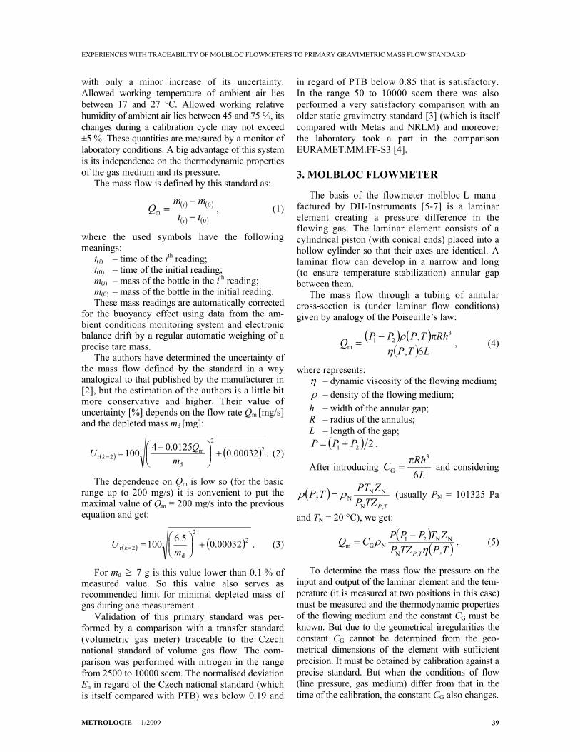
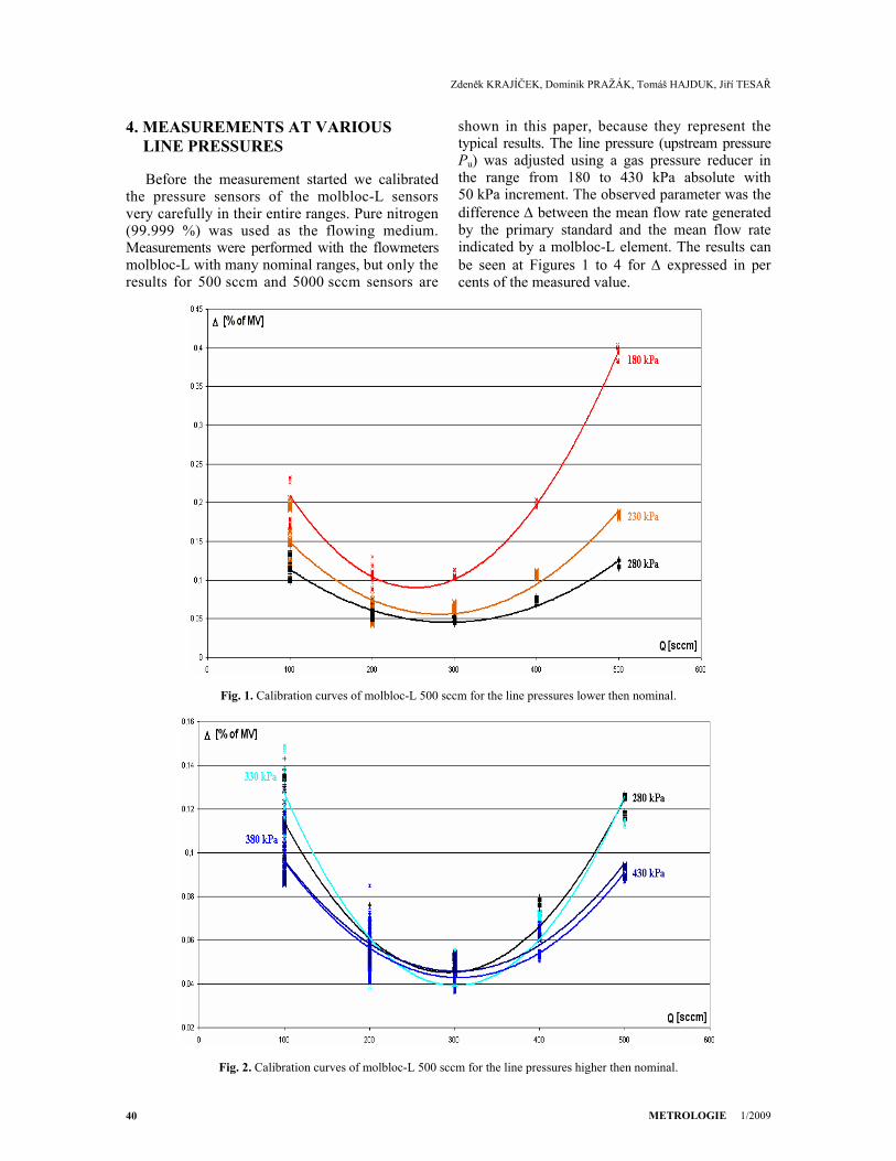
4. MEASUREMENTS AT VARIOUS LINE PRESSURES
Before the measurement started we calibrated the pressure sensors of the molbloc-L sensors very carefully in their entire ranges. Pure nitrogen (99.999 %) was used as the flowing medium. Measurements were performed with the flowmeters molbloc-L with many nominal ranges, but only the results for 500 sccm and 5000 sccm sensors are
shown in this paper, because they represent the typical results. The line pressure (upstream pressure Pu) was adjusted using a gas pressure reducer in the range from 180 to 430 kPa absolute with 50 kPa increment. The observed parameter was the difference Δ between the mean flow rate generated by the primary standard and the mean flow rate indicated by a molbloc-L element. The results can be seen at Figures 1 to 4 for Δ expressed in per cents of the measured value.
Fig. 1. Calibration curves of molbloc-L 500 sccm for the line pressures lower then nominal.
Fig. 2. Calibration curves of molbloc-L 500 sccm for the line pressures higher then nominal.

EXPERIENCES WITH TRACEABILITY OF MOLBLOC FLOWMETERS TO PRIMARY GRAVIMETRIC MASS FLOW STANDARD
METROLOGIE 1/2009 41
Fig. 3. Calibration curves of molbloc-L 5000 sccm for the line pressures lower then nominal.
Fig. 4. Calibration curves of molbloc-L 5000 sccm for the line pressures higher then nominal.
The results vary greatly with individual laminar flow elements, but two common conclusions can be made. First, the change of the calibration curve is more significant for the line pressures lower then the nominal line pressure value 280 kPa absolute. Second, the change of the line pressure has larger influence in the upper part of the range of the flow measuring element. The dependence of Δ on up-stream pressure Pu is shown in Figure 5 to illustrate this.
Finally, the second set of measurement was performed with the mentioned above molblocs. In
this case the dependence of Δ on the flow rate and downstream pressure was recorded. This dependence was the same for each flow rate for 500 sccm molbloc-L, see Figure 6.
But this feature belonged to this sensor uniquely and could not be repeated for 5000 sccm element, as can be seen in the Fig. 7.
5. CONCLUSION
The customers demand to have their flowmeters calibrated at various line pressures. The molbloc-L

Zdeněk KRAJÍČEK, Dominik PRAŽÁK, Tomáš HAJDUK, Jiří TESAŘ
METROLOGIE 1/2009 42
sensors are very important secondary calibration standards, but are sensitive to the line pressure and the manufacturer does not provide their corrections
for this. The only way is to calibrate them by a proper primary gravimetric standard at the deman-ded line pressure.
Fig. 5. Dependence of indication of molbloc-L 500 sccm on the upstream pressure.
Fig. 6. Dependence of indication of molbloc-L 500 sccm on the downstream pressure.

EXPERIENCES WITH TRACEABILITY OF MOLBLOC FLOWMETERS TO PRIMARY GRAVIMETRIC MASS FLOW STANDARD
METROLOGIE 1/2009 43
Fig. 7. Dependence of indication of molbloc-L 5000 sccm on the downstream pressure.
The resultant calibration curves of various molblocs show high variability and confirm the information obtained from the manufacturer that each piece is unique and it is impossible to calcu-late its calibration curve for changed line pressure. But ensuring traceability of these secondary standards by appropriate line pressures allows expanding the calibration services without loss of the uncertainty.
REFERENCES
[1] P. Delajoud, M. Bair, C. Rombouts, M. Girard, A Primary Calibration System For The Support Of High Perfor-mance Gas Flow Transfer Standards. ISFFM, Queretaro, Mexico (2006)
[2] M. Bair, C. Rombouts, Technical Note 6050TN09: Typical Measurement Uncertainty In Gas Flow Measured By GFS2102 Gravimetric Flow Standard. Phoenix: DH Instruments (2006)
[3] J. Tesař, D. Pražák, E. Drbálková, The New CMI (Czech Metrology Institute) Method of Metrological Ensure for Accurate Low Mass Flow. Analytical Sciences 17 (2001) Supplement i1399-i1402 - CD-ROM
[4] C. Probert, A. I. Johns, Z. Metaxiotou, An Inter-comparison Of Low Flow Gas Facilities At Eleven European Laboratories Using A molbloc Transfer Package EURAMET.MM.FF-S3 (EURAMET Project No 806). London: TUV NEL (2008)
[5] P. Delajoud, M. Girard, A High Accuracy, Portable Calibration Standard For Low Mass Flow. XIII IMEKO, Torino, Italy (1994)
[6] M. Bair, Technical Note 2011TN06A: Uncertainty Analysis For Flow Measured By molbloc-L And molbloc-S Mass Flow Transfer Standards. Phoenix: DH Instruments (2004)
[7] U.S. Patent 5,445,035, August 29, 1995, Delajoud; P. R.: Precision gas mass flow measurement apparatus and method maintaining constant fluid temperature in thin elongated flow path.
Note: The papers [1, 2, 5, 6] can be downloaded from: www.dhinstruments.com, the paper [4] from www.bipm.org and the paper [7] from www.patentgenius.com.
Revizia ştiinţifică a articolului:
Ion SANDU, doctor inginer, cercetător ştiinţific principal II, Şef al Laboratorului Mase al Institutului Naţional de Metrologie, e-mail: [email protected]. Despre autori:
Zdeněk KRAJÍČEK: şef departament Presiuni la Czech Metrology Institute, e-mail: [email protected] Dominik PRAŽÁK: autor corespondent, inginer la Czech Metrology Institute corresponding author, e-mail: [email protected] Tomáš HAJDUK: inginer la Czech Metrology Institute, e-mail: [email protected]. Jiří TESAŘ: doctor la Czech Metrology Institute, e-mail: [email protected].