experiment no. 1: object: apparatus required: description...
TRANSCRIPT

Exp ObjAppgalvconnDesEF ThestripIn bknoresiscell galvon tthe g For1) RWheresisof tinter2) Uwhein ththe l Figu.
periment N
ject: To finparatus Rvanometer,necting wi
scription oof mangan
e wire is cop B fixed pbetween thwn resistastance Q aE and pl
vanometer the wire EFgalvanome
rmula UsedResistance ere l1 = bstance X isthe bridge rchanging
Unknown rere X = unhe left gapleft end, be
ure:
No. 1:
nd the low Required: , thick coires. of the Appnin or cononnected atparallel to these strips ance X, inand in fourtlug key KG is conn
F. This keyeter otherw
d: per unit lenbalancing s connecteand l2 = the positio
resistance onknown res, l1 and l2 efore and a
resistanceCarey F
opper strip
paratus: Thstantan of t both the ethe meter sthere are f
n second eth empty s
K are connnected. At py is known
wise not.
ngth of thelength on
ed in left gbalancing
ons of X anof the givensistance corespective
after interc
e by Carey Foster’s bp, plug ke
he Carey Ff uniform cends with cscale and twfour emptyempty spaspace gh thnected in bpoint D, cn as jockey
e wire of bthe bridg
gap of the bg length ond Y. n wire Y =
onnected inely are the bchanging th
Foster’s bbridge, deey, rheost
Foster’s brcross-sectiocopper stripwo L-shapy spaces abace cd a rhe known rbetween Aontact keyy. On pres
ridge ρ = Xge wire mbridge andf the brid
= X – (l2 –n the left gbalancing he position
ridge. ecimal resat of nea
ridge is as on area is ps. Beside
ped strips Ab, cd, ef aresistance resistance YA and C. By is fixed wsing jocke
X/ (l2-l1) oeasured fr
d zero resisdge wire m
l1) ρ gap, Y = relengths of
ns of X and
sistance barly 10 oh
in the fig. stretched these strip
A and C at and gh. In
P, in thirY are connBetween twhich can ey, point D
ohm/cm. rom the lestance is comeasured f
esistance of the bridged Y
box, laclahm, given
One meteralong a m
ps there is the ends oone empty
rd empty snected. Thethe points move here
D gets conn
eft end whonnected infrom the l
of the wiree wire mea
anche cellwire and
r long wiremeter scaleone copper
of the scaley space abspace of ae leclancheB and D
e and therenected with
hen knownn right gapeft end on
connectedasured from
l, d
e e. r
e. b, a e
D, e h
n p n
d m

Procedure: 1) To determine the resistance per unit length of the bridge wire: i) First the circuit is connected as in the fig. for which decimal resistance box X is connected in the left gap ab and copper strip Y is connected in the right gap of the bridge. Now both the lower fixed ends of the rheostat are connected to terminals A and C respectively and its variable end is connected to terminal B.Thereafter the leclanche cell E and the plug key K are joined in series in between the terminals B, its other end is connected to the jockey D. ii) The variable end of the rheostat is adjusted in middle such that both the resistances P and Q are nearly equal. iii) Now inserting some resistance X through the resistance box, the jockey D is pressed on the bridge wire and it is slided on it until zero deflection is obtained in the galvanometer. In this position, the distance l1 of jockey from left end on wire is noted. iv) Thereafter the positions of resistance box X and copper strip Y are interchanged and then without changing the resistance box, again the position of jockey is adjusted on the bridge wire in order to obtain zero deflection in the galvanometer. In this position, the length l2 of the jockey on the wire from the left end is noted. v) Now the experiment is repeated three – four times by changing the resistance X from the resistance box and each time the values of l1 and l2 are noted corresponding to the value of X. vi) Then using the relationship ρ = X/ (l2-l1), the value of ρ is calculated for each observation and its mean value is calculated. 2) To determine the resistance of a given wire: i) To determine the resistance of a given wire, from the electric circuit as in the fig. The copper strip connected in the left is withdrawn and in its place the given wire is connected. ii) The above steps 2, 3, 4 and 5 in part (i) of the experiment are repeated. iii) Now using the relation Y = X- ρ (l2-l1), the value of Y is calculated from each observation and its mean value is obtained. Precaution: (1) For greater sensitivity of the bridge, the resistance connected in the four gaps of the bridge should be nearly equal. (2) Clean the ends of connecting wires with sand papers. (3) Never allow the flow of current in the circuit for long duration otherwise resistance wire will get heated which in turn increase its resistance. For this, in the circuit insert the plug in key only while taking observations. (4) Do not move the jockey on the meter bridge wire by rubbing otherwise thickness of wire will not remain uniform. (5) Initially shunt should be used while adjusting galvanometer, but near zero deflection position, it must be removed. (6) Only that resistance plug should be removed from the resistance box for which zero deflection is observed in the middle of the bridge wire. In this state sensitivity of the bridge is maximum and percentage error is minimum. (7) Except the resistance removed in the R.B box, all other plugs should be firmly tight. (8) Before pressing the jockey on the bridge wire, plug should be inserted in the plug key attached with the cell so that electric circuit gets completed before the galvanometer gets connected in the circuit.
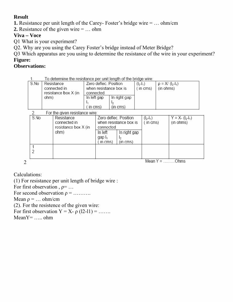
Result 1. Resistance per unit length of the Carey- Foster’s bridge wire = … ohm/cm 2. Resistance of the given wire = … ohm Viva – Voce Q1 What is your experiment? Q2. Why are you using the Carey Foster’s bridge instead of Meter Bridge? Q3 Which apparatus are you using to determine the resistance of the wire in your experiment? Figure: Observations:
2
Calculations: (1) For resistance per unit length of bridge wire : For first observation , ρ= … For second observation ρ = ………. Mean ρ = … ohm/cm (2). For the resistence of the given wire: For first observation Y = X- ρ (l2-l1) = ……. MeanY= ….. ohm

Exp Obje Appof 0resisac) Formgalv Thennow Divi Note Proc 1. ToPut ikey, the g 2. To(i) C(ii) NR ad(iii) Figu
periment N
ect: To mea
paratus Used.1MΩ, unkn
stance box to
mula Used:anometer an
n X is disconused to obta ding eq. (1)
e if θ1= θ2, re
cedure:
o find galvain plug betwK, and adju
galvanomete
o find unknConnect a andNow open a djust shunt, SIncrease R i
ure:
No: 2
sure high res
d: A high renown high ro act as shun
: As in the nd deflection
Ig = E /X+nnected andain deflectio Ig’ = E/Rby (2) , we g X=[R(G+
elation reduc X=R(C+S
anometer reween a and b ust the shunt,er resistance.
nown high red b to bring and b and c
S in order to n steps of 0.
sistance by s
esistance senresistance (Xnt (S) of gal
fig. this mn, θ1 is obtain+ G = Kθ1…
d resistance bon, θ2 in the gR +SG/S+G get
+S)/S +G] θ2
ces to S) / S………
esistance: and note the
, S, such as t
esistance: unknown re
connect a anmake deflec1 MΩ and re
substitution m
nsitive galvanX) of value lvanometer,
method, firstned. Current
………………box R is congalvanomete.S/(S+G) = K
/θ1 –G………
………………
e deflection,to reduce the
sistance intod b to bringction, θ2 in thepeat the ob
method.
nometer (G)greater thanbattery(6-8
t high resistthrough gal
………………nnected. A ser which is nK θ2 ………
……………
………………
θ, in the gale deflection t
o the circuit. known resihe galvanomservations.
), A high resn R( may bevolt), one-w
tance, X, isvanometer i……… (1) uitable valu
nearly equal o……….. (2)
……….. (3)
……… (4)
lvanometer. to half of its
Note deflecstance, R int
meter nearly e
istance box e of the ord
way key (K),
s connected s
ue of R is intor equal to θ
It should be previous va
ction θ1 in theto the circuiequal to defl
of about 0.5der of 1MΩ), two 2-way
to the batt
troduced andθ1.Current no
e fairly largealue θ. Then
e galvanomeit. With suitalection θ1.
5MΩ in step), A suitable
y key (ab and
tery through
d shunt, S, iow is
e. Then inservalue of S i
eter. able value o
s e d
h
s
rt s
f

Observations: 1 For galvanometer resistance, G: Initial Deflection = …… Value of shunt, S, to reduce deflection to half of its value = ….ohm For high resistance, X =
Result: Value of unknown resistance, X = …….ohms Calculations: Use the relation: X = [ R (G+S)/S +G] θ2/ θ1 – G = ….ohms For each set and then take mean. Sources of Error and Precautions: (i) A sensitive galvanometer should be used. (ii) Value of shunt, S, should be measured with accuracy. It is better to use a standard (SWG) copper wire along with resistance box to get nearly equal values of deflection in the two cases. (iii) The method is an approximate one. For suitable setup it is desirable to have a rough idea of the value of unknown resistance before hand.

Exp ObjAppConwireForTheR = Wheθ0 =ballθ1 =galvC = Pro(i) M(ii) (iii) Not(iv) cond(v) Kee(vi) first(vii) Figu
periment n
ject: To deparatus Usndenser (caes. rmula Usede high resis
t / 2.3026 ere t = tim= first throwistic galvan
= first throwvanometer
capacity oocedure: Make the eClose K1(iRelease th
e down theRepeat th
denser andClosing K
eping MorsAfter a m
t throw θt i) Repeat pr
ure:
no. - 3
etermine hised: Ballisapacity of t
d: stance R is
C log10 θe period ofw of spot onometer. w of spot oafter a leak
of the stand
electrical coii) and prehe Morse ke first throwhe procedud then dischK1 (ii) andse key pres
measured tiin the galvrocedure (v
igh resistanstic Galvanthe order o
given by 0 / θ1 f the leakaof light wh
of light whkage of chdard conde
onnectionsss the Mor
key K2 so tw θ0. ure of theharge throud pressingssed, open ime t seconanometer. v) and (vi)
nce by the nometer, acof 1.0 or 0.5
ge of condhen initially
hen the conharge for timenser.
s as in the frse key, i.ethat the co
e points (iugh B.G. O
g Morse kK1 (ii) andnds, (say 5
for differe
method ofccumulator5 μ.F), giv
denser throy the conde
ndenser is dme t throug
fig. . charge thndenser is
ii) and (iiiObtain meakey K2, chd close K15 or 10 sec
ent values
:
f leakage or, Morse k
ven resistor
ugh the resenser is dis
dischargedgh R.
he condensdischarged
i) several an value ofharge the (i). Start thc.) release
of t.
of a condeney, two war, stop watc
sistance. scharged th
d through th
er for 40 sd through t
times, i.ef θ0 condenser
he stop waMorse ke
nser. ay key, stanch and con
hrough
he ballistic
econds. the galvan
e. every ti
r for the satch. y and note
ndard nnection
c
nometer.
me charge
same time
e down the
e
e.
e

Observation:
Calculations: Plot a graph with t on X-axis and log10 θ0 / θ1 on Y-axis. From this graph obtain the slope as shown in figure. The slope of the curve = log10 θ0 / θt / t Value of C (given) = ….. μF = …x.10-6 Farad Therefore * R = t / 2.3026 C x log10 θ0 / θt / t = …ohms. To calculate Rleak: The procedure is same as adopted in the measurement of R except that the high resistance is never put in the circuit. (i) First charge the condenser for same time and then open key K1. (ii) Allow the condenser to stand for specific time (say t seconds) which should be measured by a stop watch. (iii) After this specific time, release the Morse key and note down the deflection θt’ of light spot on the scale due to passage of remaining charge of the condenser through the ballistic galvanometer. Thus t’ is the time for which the condenser is allowed to leak through itself and θt’ is the first throw of the galvanometer corresponding to the charge left on condenser after leakage for time t’. (iv) Repeat this process for different intervals of time for the condenser to leak through itself and note corresponding throws of the galvanometer. (v) Since each time condenser in charge for the same time θo will remain the same as taken in the experiment of determining R. Result: Resistance of the given resistor is ….ohms. Sources of Error and Precautions: (i) The galvanometer coil should be made properly free. (ii) Tapping key should be used across the galvanometer. (iii) Condenser should be free from dielectric loss. (iv) After observing θ0, the galvanometer coil should be at rest for observing the value of θt. (v) Thus true value of high resistance can be calculated by above formula. R has been calculated previously. VIVA VOCE 1. What do you leak in order to determine high resistance? 2. What is the time constant of R-C circuit? 3. Why do you say that it is method of determining high resistance? 4. What is the order of resistance you determine?

Exp Obj AppcathoperPlatcom Figu
Pro(i) R(ii) Pray as p(iii) Vol
periment N
ject: Meas
paratus Ushode ray carate the tubtes; An am
mmutator.
ure:
ocedure: Record the Place the stube inside
possible to Switch on
tage” and a
No 4:
surement o
sed: A cathan be placebe (b) to op
mmeter rang
constants solenoid sue the solenavoid the s
n the poweradjust the v
f e/m by h
hode ray tued; A contperate the ge (range d
of the soleuch that itsnoid at the cstray magnr supply unvoltage, V
elical meth
ube, a soletrol which solenoid (c
d.c. one am
enoid and t axis lies incentre. Thenetic field.nit. Turn th
V, to any de
hod.
enoid of procontains unc) to provid
mpere); Vol
tube. n the east we power un
he potentioesired valu
oper dimennder it a pode variableltmeter (ra
west directnit should b
ometer mare.
nsion, in thower suppe a.c.voltagnge 1.5 k-v
tion. Mounbe kept as
rked “Acce
he interior ly and conge for deflevolts); One
nt the cathofar away
elerating
of which antrols (a) toection e
ode
a o

With the help of F and I make a fine and clear spot on the cathode ray tube. (iv) Apply a.c deflecting potential to one set of plates, say X-plates. A deflection of 2 cm. is adequate for the experiment. Now turn on the solenoid current and increase the current till the line is reduced to a small point. Reverse the solenoid current and readjust the control to a fine point. The average of these two currents in amperes is I. (v) Repeat procedures of point (iv) above with Y-plates. Keep deflection 2cm. Find I. (vi) Now repeat the whole procedure from point (iii) to (iv) with three other values of accelerating voltages. It will be necessary to refocus the spot in the tube at each voltage. Result: e/m = ….emu/gm. = ….coul/kg. Observations: (A) 1. Distance between the edge of X-plate and the screen lx, = …cm. 2. Distance between the edge of Y-plate and the screen ly, = …cm. 3. Diameter of the solenoid D, = …..cm. 4. Length of the winding L, = …cm. 5. Number of turns, N = ….cm. 6. Cos θ = L / √ (L2 + D2) = ….
Calculations: (A) Using X-plates: (e/m)x = [5 x 10⁹( L /Nlx cosθ)2] V/I2 e.m.u./gm. (B) Using Y-plates: (e/m) = [5 x 10⁹(L/Nly cosθ)2] V/I2 e.m.u./gm. The mean of these two values gives the value of e/m. Sources of Error and Precautions: (i) Accelerating voltage should be applied carefully. (ii) Obtain a clear, well focused, sharp line on screen of cathode ray tube. It should be of moderate size.

Experiment No 5: Object: To determine the ionization potential of the gas filled thyratron. Apparatus: A thyratron tube 884, two grid bias supplies (0-30 V), two voltmeters (0- 30 V), a micro ammeter (or a sensitive galvanometer), two rheostats. Procedure: (i) Make the electrical connections as in the fig. (ii) Keep both the grid and the plate at zero potential. There will be some deflection in the μA on heating the filament. To reduce it to zero, apply just necessary negative potential to the plate (keeping grid at zero potential).Keep this plate voltage constant throughout the experiment. (iii) Now apply positive potential to the grid. Increase it gradually in small steps and corresponding deflections in the micro ammeter (or galvanometer). It will be observed that for particular value of grid, deflection increases very much. (iv) Draw a graph between deflection (on Y-axis) and grid potential (on X-axis) as in fig. (v) From the curve, the value of grid voltage corresponding to steep rise of micro ammeter deflection (showing plate current) is calculated. This gives the ionization potential; of the gas filled in thyratron. Figure :

(vi) Remove the micro ammeter from the plate circuit and connect it in the grid circuit as in the fig. (vii) Keeping the same plate potential (fixed in the point (ii)), give negative potential to the grid just to reduce any deflection in μA to zero. Note down this value which will be subtracted from the calculated value of ionization potential to find the correct value of the latter. Result: Ionization potential of the gas filled in thyratron valve = value from graph-velocity correction = volts. Standard Value = ….volts Percentage Error = …. Sources of Error and Precautions: (i) Micro ammeter or galvanometer used in the experiment should be very much sensitive. (ii) Velocity correction should be determined carefully. Observations: (A) Readings for ionization Potential: Plate Potential = ….volts. (B) Velocity Correction: Grid voltage = ….volts Calculations: Plot the graph in grid voltage and corresponding deflection in micro ammeter. Find the value of ionization potential. VIVA VOCE 1. What do you mean by ionization potential? 2. Of what substance are you finding the ionization potential? 3. What is gas in the thyratron valve? 4. What is a thyratron valve? 5. What is their construction?

Exp Objcarryestim. AppcommconnForThe F = 2Wher = ri = cx = dIf F iF = HThusF = 2
Proc(i) Pcoil. wholneedin th(ii) Tcurrewithcurrethe dlittleto re
periment N
ject: To ploying current mate from it
paratus Remutator, plu
nective wiresrmula Used
field F along2 π n r2 i / 1ere n = numbadius of the urrent in amdistance of this made perpH tan θ s 2π n r2 i /10
cedure: lace the magBy rotating
le apparatusdle and its imhe same vertiTo set the coent in one di
h the help of ent and againdeflection. Ife, adjust poinead 0-0 till th
No 6:
ot graph showand to the radius of
equired: taug key and s. d: g the axis of0 (x2 + r2) 3/2
ber of turns icoils
mpere flowinghe point frompendicular to
0(x2 + r2) 3/2 =
gnetometer c the in the horiz
mage all lies ical plane. R
oil exactly inirection commutatorn note downf the deflectinter ends hese deflectio
wing the var
f the coil
angent galva
f a coil is giv2
in the coil
g in the coil m the centreo H earth’s
=H tan θ
compass box
zontal plane,
Rotate the comn the magneti
r and note don ions are equa
ons become
riation of ma
anometer of
ven by
of the coil.horizontal f
x on the slidi
set the coil
mpass box tiic meridian s
own the defl
al then the co
equal.
agnetic field
the Stewart
field, the de
ing bench so
in the magne
ill the pointeset up the el
ection of the
oil is in mag
with distanc
and Gee typ
eflection θ o
o that its mag
etic meridian
er ends read ectrical conn
e needle. No
gnetic meridi
ce along the
pe, a strong b
of the needle
gnetic needle
n roughly. In
0-0 on the cnections as i
w reverse th
ian otherwis
axis of a cir
battery, a rhe
e is given by
e is at the ce
n this case th
circular scalein the fig. Se
he direction o
se turn the ap
rcular coil
eostat, a
y:
entre of the
he coil,
e. end the
of the
pparatus a

(iii) Using rheostat Rh adjust the current such that the deflections of nearly 70o to 750 is produced in the compass needle placed at the centre of the coil. Read both the ends of the pointer. Reverse the direction of the current and again read both the ends of the pointer. The mean of four readings will give the mean deflection at x = 0. (iv) Now shift the compass needle through 2cm. each time along the axis of the coil and for each position note down the mean deflection. Continue this process till the compass box reaches the end of the bench. (v) Repeat the measurements exactly in the same manner on the either side of the coil. (vi) Plot a graph taking x along the axis and tan θ along the y-axis. (vii) Mark the points of inflexion on the curve. The distance between the two points will be the radius of the coil. Observation:
Result: The graph shows the variation of the magnetic field along the axis of a circular coil carrying current. The distance between the points of inflexion P, Q and hence the radius of the coil = …cms. Precautions and Sources of Error: (i) The coil should be carefully adjusted in the magnetic meridian. (ii) All the magnetic materials and current carrying conductors should be at a considerable distances from the apparatus. (iii) The current passed in the coil should be of such a value as to produce a deflection of nearly 750. (iv) Current should be checked from time to time and for this purpose am ammeter should be connected in series with the battery. (v) Parallax should be removed while reading the position of the pointer. Both ends of the pointer should be read. (vi) The curve should be drawn smoothly. VIVA VOCE 1. What is the direction of the field? 2. Is the field uniform at the centre? 3 Hoe can you get wider region of uniform field? 4 Is it true for any direction of current in the two coils? 5 If any current carrying conductor is placed close to the coil ten will it effect your measurement?

EXP Objeby m Appcoup FormThe
WheE = rL = l Proc(i) Tresis(ii) Nso adthe p(iii) junctthat (iv) decr(v) C(vi) therm(vii) placethirdNowtemp Figu
PERIMEN
ect: To studmeans of a po
paratus Usedple, high resi
mula Used: thermo elect
ere ρ = resistresistance talength of the
cedure: The electric stance of 1,0Now jockey djusted that potential diffOpen K2 (ition has becagain a balaRepeat the easing temp
Calculate thePlot the gra
mo e.m.f.’s, In order to
ed in a wated of naphthalw calculate thperature. Thi
ure:
NT NO. 7:
dy the variatotentiometer
d: Potentiomistance box,
tric e.m.f. (e
tance per uniaken out frome potentiome
connections18 ohms is tis placed atthere is no dference acroi) and connecome steadyance point is
above proceratures of t
e value of e.maph betweenas ordinates determine
er bath for hlene melts, the e.m.f. coris temperatu
:
ion of the thr and to deter
meter( coil tyhigh resistan
e) developed
it length of tm the resistaneter wire wh
s are made taken out frot the point Adeflection inss the R.B. T
ect K2 (ii) s, press the jobserved. N
cedure and dthe hot junctim.f generaten the tempers. The curve the melting
heating. The the balance prresponding
ure will be th
hermo electrrmine (i) the
ype or 10 wnce rheostat
d in a thermoe
the potentiomnce box (resen thermo e
as shown iom the resist
A and the keyn the galvanoThis is knowo that the thockey on th
Note the lengdetermine thion.
ed using the frature differeis of the shapoint of nahot junction
point is obtato this leng
he melting po
ric e.m.f. wite neutral tem
wire), standar, one way ke
ocouple is ob= ρ El / R
meter wire,sistance acro.m.f. is balan
in fig. 2 Thtance box. y K1 and K2ometer. In th
wn as standarhermocouple
he wire by adgth (l) of the he balancing
formula usedences of tw
ape as shownaphthalene, wn of the therained on the gth. With theoint of napht
th temperatumperature, (ii
rd cadmiumey, two way
btained with
oss which thenced.
he rheostat
2 (i) are closhis way the erdization of te is in circudjusting the potentiometg lengths of
d. o junctions
n in figure. we take the rmocouple ispotentiomet
e help of thethalene.
ure, for a coi) melting po
m cell, batteryand connect
the help of t
e standard ce
Rh should b
sed. The vale.m.f. of stanthe potentiomit. When thelength of th
ter wire fromf the potent
as abscissae
naphthalenes placed in nter. Note dowe graph deter
opper-iron thoint of napht
y, a coppertion wires.
the following
ell is balance
be of high
lue of the rhndard cell is meter wire.e temperaturhe potentiomm A to balanctiometer wir
e and the co
e in a tube.naphthalenewn the balanrmine the co
hermocouplethalene.
iron thermo
g formula:
ed)
value and a
eostats Rh i balanced by
re of the hometer wire socing point. re at variou
orresponding
This tube i. When twoncing lengthorresponding
e,
-
a
s y
ot o
s
g
s -
h. g

Observations: (i) E.M.F. of the standard cadmium cell E = …volts (ii) Resistance, introduced in the resistance box R.B. = …ohms (iii) Resistance per unit length of the potentiometer wire (ρ) = …ohm/cm (iv) Table for the determination of thermo e.m.f.’s with temperature. Room Temperature = ….oC (v) Balancing length when naphthalene melts = …cm Calculations: (i) At ….oC, e = E ρ l / R = …micro volts (ii) At ….oC, e = E ρ l / R = …micro volts Similarly calculate for other temperatures. Result: (i) The variation of thermo e.m.f. of the copper iron thermocouple with temperature is shown in the graph Neutral temp. from graph = …oC (ii) Melting point of naphthalene = …..oC Standard Result: The neutral temperature for … couple = …oC. Melting point of naphthalene = …oC Precautions and Sources of Error: (i) If the resistance per unit length ρ of the potentiometer wire is not known, determine with the help of a post office box. (ii) It is essential to check the standardization of the potentiometer after two or three readings. (iii) The ends of connections wires should be properly cleaned. (iv) The battery employed in this experiment should be fully charged. (v) The jockey should be pressed gently and momentarily. (vi) The galvanometer employed in this experiment should be a sensitive one and it should be shunted in the initial stages of locating the null point. (vii) The temperature of the hot junction should be recorded at the time of taking the balance reading of potentiometer. VIVA VOCE 1. What is thermocouple? 2. What is thermo-electric effect? 3. On what factors does the direction of thermoelectric current depend? 4. What is neutral temperature? 5. Is it same for every thermocouple? 6. What is temperature of inversion? 7. Is it same for every couple? 8. What is their value for Cu-Fe thermocouple? 9. What are the values of thermo e.m.f. for the following couples? Antimony-bismuth couple, Copper- constantan couple and Copper-iron. 10. What is Peltier Effect? 11. What is Thomson Effect?
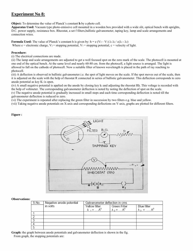
Experiment No 8: Object: To determine the value of Planck’s constant h by a photo cell. Apparatus Used: Vacuum type photo-emissive cell mounted in a wooden box provided with a wide slit, optical bench with uprights, D.C. power supply, resistance box. Rheostat, a set f filters,ballistic galvanometer, taping key, lamp and scale arrangements and connection wires. Formula Used: The value of Planck’s constant h is given by: h = e (V2 – V1) λ1 λ2 / c(λ1 - λ2) Where e = electronic charge, V2 = stopping potential, V1 = stopping potential, c = velocity of light. Procedure: (i) The electrical connections are made. (ii) The lamp and scale arrangements are adjusted to get a well focused spot on the zero mark of the scale. The photocell is mounted at one end of the optical bench. At the same level and nearly 60-80 cm. from the photocell, a light source is arranged. The light is allowed to fall on the cathode of photocell. Now a suitable filter of known wavelength is placed in the path of ray reaching to photocell. (iii) A deflection is observed in ballistic galvanometer.i.e. the spot of light moves on the scale. If the spot moves out of the scale, then it is adjusted on the scale with the help of rheostat R connected in series of ballistic galvanometer. This deflection corresponds to zero anode potential as key K1 is open. (iv) A small negative potential is applied on the anode by closing key k1 and adjusting the rheostat Rh. This voltage is recorded with the help of voltmeter. The corresponding galvanometer deflection is noted by noting the deflection of spot on the scale. (v) The negative anode potential is gradually increased in small steps and each time corresponding deflection is noted till the galvanometer deflection is reduced to zero. (vi) The experiment is repeated after replacing the green filter in succession by two filters e.g. blue and yellow. (vii) Taking negative anode potentials on X-axis and corresponding deflections on Y-axis, graphs are plotted for different filters. Figure :
Observations:
Graph: the graph between anode potentials and galvanometer deflection is shown in the fig. From graph, the stopping potentials are:

For yellow filter V1 = ….volts Foe green filter V2 = …..Volts For blue filter V3 = ….volts. Calculations: Electronic charge e = 1.6 x 10⁻¹⁹
coulombs Speed of light c = 3 x 10⁸ m/sec. Wavelength of yellow filter λ1 = ………A
0 = ….m
Wavelength of green filter λ2 = ……… A0
= ….m Wavelength of blue filter λ3 = ……… A
0 = ….m
1. for yellow and green filters h = e (V2 – V1) λ1 λ2 / c (λ1 - λ2) = ………..joule-sec. 2. for green and blue filters: h = e (V3 – V2) λ2 λ3 / c (λ2 - λ3) = ………..joule-sec. 3. for yellow and blue filters: h = e (V3 – V1) λ1 λ3 / c (λ1 - λ3) = ………..joule-sec. Mean value of Planck’s constant = ….+….+…./3 = ….joule-sec. Standard Value: Standard value of Planck’s constant = 6.625 *10 -34joule-sec Percentage Error: % error = experimental value ~ standard value / standard value x 100 = …. % Result: The value of Planck’s constant = …..Joules-sec. Sources of Error and Precautions: (i) The experiment should be performed in a dark room to avoid any stray light to photocell. (ii) The observations should be taken by altering anode potential in small steps of 0.05 volts (iii) Corresponding to zero anode potential, the deflection of light spot on scale should be adjusted at its maximum value. (iv) Smooth graphs should be plotted. (v) Stopping potentials should be read carefully. (vi) The experiment should be performed at least with three filters.

Experiment no 9: Object: To determine the self inductance of given coil by Rayleigh’s method. Apparatus Used: Post office box, ballistic galvanometer, stop watch, decimal ohm box, an accumulator, given inductance, rheostat ( 4 or 5 ohms.), tapping key, double key, a stretched resistance wire and connection wires. Formula Used: Self inductance (L) of the coil is given by: L = r/φ T/2π .θ (1+λ/2) Where r = small resistance (0.1 or 0.01 ohm) introduced in series with the inductance, φ = steady deflection in ballistic galvanometer when r is introduced in the circuit, T = time period of the coil of galvanometer, θ = first throw of the galvanometer when inductance L is employed in the circuit, λ = logarithmic decrement = 2.3026 x 1/10 log10 θ1/ θ11 Where θ1 and θ11 are first and eleventh observed throw of the galvanometer respectively. Procedure: (i) Set the galvanometer and lamp and scale arrangement such that the spot of light moves freely on both sides of zero of the scale. (ii) Make the electrical connections as in the fig. (iii) Fix the ration P: Q at 10:10. Pressing K1 and K2 adjust the resistance in R arm and the sliding contact on r’ such that there is no deflection in the ballistic galvanometer. Here first of all the battery arm should be adjusted to have a near balance with the help of R and thenrheotat r’. In this case the resistance, r in resistance box should be zero. (iv) Keeping K1 and K2 pressed introduce a small resistance say 0.01ohm in the resistance box and obtain the steady deflection φ in the galvanometer. (v) Repeat the above procedure for other small values of r and obtain the steady deflection φ in each case. (vi) Keeping r = 0 again obtain the balance point. With K2 keeping pressed, break the cell circuit by releasing K1. Note down the first throw. Repeat this observation two or three times, each after checking steady balance. (vii) Now to note θ1 and θ11 first break cell circuit by releasing key, K1 and then immediately after it, release galvanometer key K2. the spot will oscillate on the scale. Measure θ1 and θ11. Repeat the process three or four times. (viii) Now disconnect galvanometer from the bridge and by touching its connecting wires with mouth, make its coil oscillating. Note the time for different oscillations and then calculate the time period T of the galvanometer coil.

Figu
Obs (1):
(2) R
Cal Res
ure:
servations
Reading f
Reading fo
culations:
sult: The se
s
for the dete
or determin
λ = 2.30 L = r/φ Telf inducta
ermination
nation of th
26 x 1/10 T/2π .θ (1+
ance of the
n of θ and Φ
he time per
log10 θ1/ θ+λ/2) = …coil L = …
Φ
riod
θ11 ….henrys.….henrys.
Precautions and Sources of Error: (i) The galvanometer coil should be freely moved in the space between the pole pieces. (ii) Tapping key should be connected across the galvanometer (iii) To get a suitable deflection in the galvanometer a high adjustable resistance should be connected in series with cell. (iv) All resistances used in the experiment should be non inductive. (v) To secure maximum sensitiveness of the bridge all the four arms of the bridge should have nearly equal resistance. (vi) The connection wires should be uncoiled. (vii) The resistance introduced in the resistance box should be very small so that it may not affect the value of the steady current in that branch appreciably. (viii) While determining the time period of the galvanometer, the galvanometer circuit should be kept open. (ix) Keys K1 and K2 may have to be released in quick succession by personal judgment. For better results a Raleigh key should be used. VIVA VOCE 1 Define self inductance. 2 What is the unit of self inductance? 3 Define a Henry. 4 Why do you take inductance coil in the form of helix, and not as a straight conductor? 5 Upon what factors does the value of flux depend? 6 Why do you observe steady deflection by introducing a small resistance ® in the circuit? Why not large resistance? 7 What type of connecting wires should be used and why? 8 Suppose L1 and L2 be the self inductance of the two circuits and k be coupling coefficient between them, then what is mutual inductance?

Exp Objethe n Appand samm Formapplithat cryst(i) H(ii) HWhe= VH(iii) N (iv) H (v) M Proc1 Placonn2 Alsemimilli3 ChIx va4 Mein th Figu
periment 1
ect: To studynumber of ch
paratus Reqsearch coil,
meter, keys.
mula Used: ied along Z-are normal ttal is μ, then
Hall voltage, Hall coefficiere VH is in H /Ix . d/BZ mNo. of charg
Hall angle: φ
Mobility: mμ
cedure: ace the specinections as inlow some cuiconductor civoltmeter anhange value oalues. It willeasure magn
he crystal, Bz
ure:
10:
y hall effect harge carrier
uired: A reccalibrated fl
As shown in-axis. Currento Y-axis. Lxn actual magn
VH, is measuent: RH = VHvolts, Ix is in
met3/coulomge carriers pe φ = VH /Vx . Wμ = φ / BZ ra
imen in the mn fig. urrent, Ix, wicrystal along nd Vx by voof Ix in stepl be a straighnetic field, B
z = μB.
in an N-typrs per unit vo
ctangular slaux meter to
n the fig. d int, Ix, is madx is the lengtnetic field wured with thH /Ix . d/BZ .n amperes, d
mb. er unit volum n = -1/RWhere e = 1
. lx /b rad. Where lx and.met2 / We
magnetic fie
ith the help oX-axis. Me
oltmeter. s by rheosta
ht line whoseB, with a gau
e semiconduolume, (iii) H
ab of semicomeasure ma
s the thicknede to flow aloth of the cry
within the cryhe help of mi
104 met.3/cd is in meter
me in the semRH .e met.3
1.6 x 10⁻¹⁹ co
nd b both areeber.
eld of the stro
of rheostat, Rasure Hall v
t, Rh, and noe slope will bss meter or f
uctor. To detHall angle an
onductor crysagnet field or
ess along Z-aong X-axis. stal along X
ystal is Bz = illivoltmetercoulomb rs and BZ in g
miconductor
oul.
e in meter.
ong magnet
Rh, to flow tvoltage, VH, w
ote correspobe given by Vflux meter an
termine (i) Hnd mobility.
stal of thicknr ballistic ga
axis of the cHall voltage
X-axis. If permμB.
r.
gauss. If BZ
r crystal, n, i
and make ot
through thewith the help
nding valuesVH / Ix. nd find the a
Hall voltage
ness about 0alvanometer,
crystal. Magne VH, is devemeability of
is measured
is given by:
ther
p of
s of VH and
actual field
and Hall coe
.3 mm, elect millivoltme
netic field, Beloped acrosf the medium
d in weber/m
efficient, (ii)
tromagnet, eter, battery
B, is also ss the faces m of the
met2 then RH
)
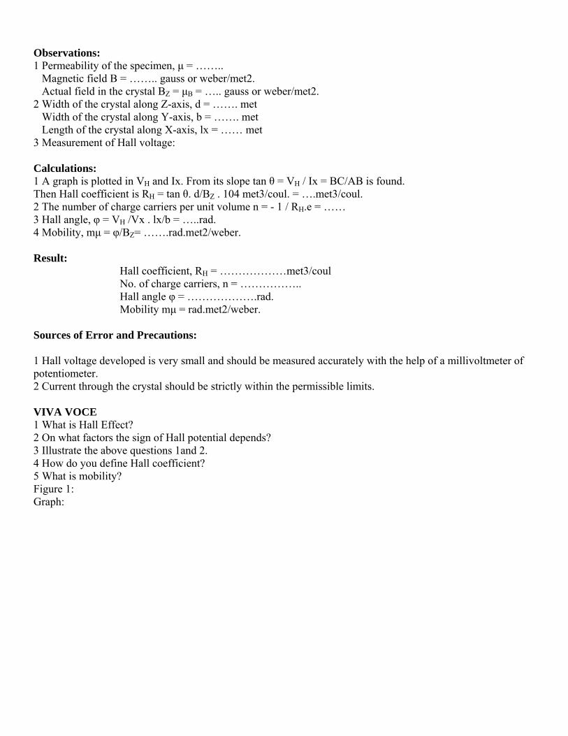
Observations: 1 Permeability of the specimen, μ = …….. Magnetic field B = …….. gauss or weber/met2. Actual field in the crystal BZ = μB = ….. gauss or weber/met2. 2 Width of the crystal along Z-axis, d = ……. met Width of the crystal along Y-axis, b = ……. met Length of the crystal along X-axis, lx = …… met 3 Measurement of Hall voltage: Calculations: 1 A graph is plotted in VH and Ix. From its slope tan θ = VH / Ix = BC/AB is found. Then Hall coefficient is RH = tan θ. d/BZ . 104 met3/coul. = ….met3/coul. 2 The number of charge carriers per unit volume n = - 1 / RH.e = …… 3 Hall angle, φ = VH /Vx . lx/b = …..rad. 4 Mobility, mμ = φ/BZ= …….rad.met2/weber. Result: Hall coefficient, RH = ………………met3/coul No. of charge carriers, n = …………….. Hall angle φ = ……………….rad. Mobility mμ = rad.met2/weber. Sources of Error and Precautions: 1 Hall voltage developed is very small and should be measured accurately with the help of a millivoltmeter of potentiometer. 2 Current through the crystal should be strictly within the permissible limits. VIVA VOCE 1 What is Hall Effect? 2 On what factors the sign of Hall potential depends? 3 Illustrate the above questions 1and 2. 4 How do you define Hall coefficient? 5 What is mobility? Figure 1: Graph:

Exp Obje Appconn Proc (A) F(i) C(ii) Wread(iii) P (B) R(i) Mbias Figu
Obs
periment
ect: To dra
paratus Renection wire
cedure:
Forward BConnectionsWith the helding of currePlot a graph
Reverse BMake the cosing.
ure:
servations:
no 11:
aw the chara
quired: traes.
Biasing: s are made lp of rheostent in millimh in applied
iasing: onnections a
:
acteristics o
ansistor, mil
as in the fitat, apply dmeters. d voltages a
as in the fig
of PN junct
limeter and
g. ifferent volt
and corresp
g. and proce
tion diode.
d micro amm
tages to the
ponding cur
eed exactly
meter, batte
e PN junctio
rrents.
y in the sam
ery, rheosta
on and note
me way as o
at, voltmete
e the corres
opted for fo
er and
sponding
orward

Calculations: (Graph plotting): Plot two graphs- one for forward and other for reverse biasing between voltages applied and the corresponding currents
Result: The characteristic of junction diode ( ) are shown in the graphs. Sources of Error and Precautions: (i) To avoid over heating of the transistor, current should not be passed for long durations. (ii) Voltages applied should be well below the safety limit of the transistor. (iii) Connections should be made carefully. VIVA-VOCE: 1. What is a PN junction diode? 2. What do you mean by P-type germanium and N-type germanium? 3. What property PN junction exhibits? 4. What is the order of currents in the above two cases? 5. Mention the order of voltages with it. 6. What if high voltage is applied in forward bias? 7. Have you heard of turn over voltage?

Experiment No. 12: Object: To determine the energy band gap of a semiconductor (germanium) using four probe method. Apparatus Required: Probes arrangement (it should have four probes, coated with zinc at the tips. The probes should be equally spaced and must be in good electrical contact with the sample), Sample (germanium or silicon crystal chip with non-conducting base), Oven (for the variation of temperature of the crystal from room temperature to about 2000C), A constant current generator (open circuit voltage about 20 V, current range 0 to 10 mA), Millivoltmeter (range from 100mV to 3V, electronic is better.), power supply for oven, thermometer Formula Used: The energy band gap, Eg, of semiconductor is given by Eg = 2k. 2.3026 x log10 ρ / 1/T(in K) in eV. Where K is Boltzmann constant equal to 8.6 x 10⁻⁵ ev/deg., and ‘ρ’is the resistivity of the semiconductor crystal, given by ρ = ρo / f (W/s) Where ρo = V/I x 2πs. For function f (W/s) refer to the data table given in the calculations. S is the distance between the probes and W is the thickness of semi conducting crystal. V and I are the voltages and current across and through the crystal chip. Procedure: Connect one pair of probes to direct current source through milliammeter and other pair to millivoltmwter. Switch on the constant current source and adjust current I, to a desired value, say 2 mA. Place four probe arrangements in the oven. Fix the thermometer. Connect the oven power supply and start heating. Measure the inner probe voltage V, for various temperatures. Figure:
Observations: (i) Distance between probes (s) = ……mm (ii) Thickness of the crystal chip (W) = ……mm (iii) T and V for current (I) = ……..mA(constant) Table 1

Calculations: First find resistivity, ρ, corresponding to temperatures in K using the relation: ρ = ρo / f(W/s), Where ρo = V / I x 2πs = ….ohm.cm. Corresponding to different values of V, there will be different values of ρo. Find them after putting for I and s from the table. Find W/s and then corresponding to this value of the function f (W/S) from the following table:
If any W/s value is not found in the table then plot a graph in these (W/s) and f (W/s) values. From graph the desired value of f (W/s) corresponding to any value of resistivity, ρ, for various values of ρo i.e. for various values of V which correspond to various values of temperature and tabulate as follows: Table 3
Finally plot a graph in (1/T x103) and log 10 ρ as in fig. Find the slope of the curve AB/BC = log 10 ρ / (1 / T) x 1000. So the energy band gap of semiconductor (germanium) is given by: Eg = 2k. 2.3026 x log10 ρ / 1/T = 2k x 2.3026 x AB/BC x 1000 = 2 x 8.6 x 10-5 x 2.3026 x AB/BC x 1000eV = 0.396 x AB/BC eV Standard Result: Eg = ………..eV for Germanium Eggs = 0.7eV Percentage Error: = ………………. Result: energy band gap for semiconductor (….) is Eg = ……….eV Sources of Error and Precautions: The resistivity of the material should be uniform in the area of measurement. The surface on which the probes rest should be flat with no surface leakage. The diameter of the contact between the metallic probes and the semiconductor crystal chip should be small compared to the distance between the probes VIVA VOCE 1 What is energy and gap? 2 How do you differentiate between a conductor, an insulator and a semiconductor in relation to energy gap? 3 do you know about intrinsic and extrinsic semi-conductor? 4 why a semi-conductor behaves as an insulator at zero degree Kelvin? 5 What is the advantage of four probe method over other methods of measuring resistivity?

Exp ObjeAppcalcumA) FormHystcycleF = 5squa Proc(i) AfrequobtaiB tehorizexpe(ii) Vwrite(iii) form Figu
periment N
ect: To deterparatus Requlated, capac), rheostat (1
mula Used: teresis loss pe. Where i =50c/s, Area cares of mm.
cedure: Apply some uency selectin a suitablerminals to Yzontal gain eriment. Vary rheostae on it V andRe-sketch a
mula.
ure :
No 13:
rmine the hyquired: A scitor (8μF). R0 ohm).
per unit volu= current in pcan be count
voltage, V,tor of CRO e B-H curve Y-plates. Noand vertica
at, Rh, to somd i values. all B-H curve
ysteresis lossstep down tResistor (50
ume per cycprimary windted in millim
with the heto external.on the scree
ote voltage, al gain of a
me other val
es with V an
s by C.R.O.ransformer,
0 KΩ potenti
le is given bding in ampe
meter2 from t
elp of rheos. Now adjusen. To obtainV, and curr
amplifiers is
lue. i.e. selec
nd I values o
specimen tiometer), A.C
by: W = i.V.ere,V = voltathe centimete
stst, Rh. Const gain of thn a correct crent, i. Tracs selected, t
ct new value
on a centime
transformer C Voltmeter
.area of B-Hage across per graph of B
nnect XX phe horizontalcurve adjust ce the curve they are to
es of V and
eter graph. F
hysteresuis r (0-10 V), A
H loop / f.π arimary wind
B-H loop. Co
plates and Yl and verticavalue of R, on the tracbe kept co
i. Trace the
Find the are
loss of whA.C milliamm
area of rectading correspoount the sma
YY plates ofal amplifiersalso may int
ce paper. Noonstant thro
B-H curve o
a in mm2 req
hich is to bemeter (0-500
angle joules onding to i.all
f C.R.O.keeps of CRO toterchange Bote that onceough out the
on paper and
quired in the
e 0
/
p o -e e
d
e

Observations:
Hysteresis loss per unit volume per cycle is given by W = i.V Area of B-H loop / f.π.Area of rectangle = ……..joules/cycle Result: The hysteresis loss of the specimen transformer per unit volume per cycle is ………….joules/cycle. Precautions: (i) Attenuator of C.R.O should be kept at a suitable position. The positions of X and Y amplifiers should not be disturbed after adjusting it once in the whole experiment. (ii) Variations in the supply voltage will affect the tracing of the curve on the paper. (iii) Handle C.R.O carefully.