experiment safety assurance package for the 40- to 50- gwd
TRANSCRIPT
INEEL/EXT-02-00826
Experiment Safety Assurance Package for the 40- to 50-GWd/MT Burnup Phase of Mixed Oxide Fuel Irradiation in Small I-Hole Positions in the Advanced Test Reactor S. T. Khericha June 2002
Idaho National Engineering and Environmental Laboratory Bechtel BWXT Idaho, LLC

INEEL/EXT-02-00826
Experiment Safety Assurance Package for the 40- to 50-GWd/MT Burnup Phase of Mixed Oxide Fuel
Irradiation in Small I-Hole Positions in the Advanced Test Reactor
S. T. Khericha
June 2002
Idaho National Engineering and Environmental Laboratory Idaho Falls, Idaho 83415
Prepared for the U.S. Department of Energy Office of Nuclear Energy
Under DOE Idaho Operations Office Contract DE-AC07-99ID13727

Experiment Safety Assurance Package for the 40- to
50-GWd/MT Burnup Phase of Mixed Oxide Fuel
Irradiation in Smalll-Hole Positions
in the Advanced Test Reactor
Preparedby ~ ~- 7-2. 5-02.~ --~~ri;;';;-: ~ , ~;e --
Approved by ~ Q ~ k= "7 .z. S .°~
R. C. Pedersen. Date
Reviewed by K~ ~ I ~ ~~~~ -~ ~
~r Rev.ewer Date
Reviewed by ~ .7- -" J-
uclear Engineering Date
Approved .,
.sor teLMIR ,
'0ate

iii
CONTENTS
ACRONYMS..............................................................................................................................................vii 1. SCOPE................................................................................................................................................ 1 2. IRRADIATION HISTORY................................................................................................................ 7 3. CAPSULE ASSEMBLY IDENTIFICATION AND LOADING PATTERN ................................. 10 4. HAZARD CLASSIFICATION ........................................................................................................ 18 5. PROCESS DESCRIPTION.............................................................................................................. 19
5.1 Process Flowchart .................................................................................................................. 19 5.2 Descriptions ........................................................................................................................... 19
5.3 Safety Envelopes.................................................................................................................... 23 6. DEMONSTRATION OF COMPLIANCE....................................................................................... 26 7. SAFETY ANALYSIS ...................................................................................................................... 35
7.1 Verification of ASME B&PV Code Requirement for Stainless Steel Capsule .................... 35 7.2 Irradiation of the Experiment in the ATR .............................................................................. 35
7.2.1 Condition 1, Normal Power Operation in the Reactor................................................. 35 7.2.2 Condition 2 Anticipated Faults.................................................................................... 41 7.2.3 Condition 3, Unlikely Faults........................................................................................ 42 7.2.4 Condition 4, Extremely Unlikely Faults ...................................................................... 43
7.3 Canal Activities: Steps A, B, D, E, F, H, I, J, L, M, P, and N ............................................... 45 7.3.1 Condition 1, Normal Operations.................................................................................. 45 7.3.2 Condition 2, Anticipated Faults................................................................................... 45 7.3.3 Condition 3, Unlikely Faults........................................................................................ 45 7.3.4 Condition 4, Extremely Unlikely Faults ...................................................................... 46
7.4 Transport of Unirradiated or Irradiated Capsule Assemblies within TRA ............................ 46 7.5 Cask Handling and Shipping Activity.................................................................................... 47
8. PLANT PROTECTION CRITERIA................................................................................................ 48 8.1 Condition 1, Events................................................................................................................ 48
8.1.1 Irradiate the test assembly ........................................................................................... 48 8.1.2 Canal Activities ........................................................................................................... 48 8.1.3 Transport Unirradiated or Irradiated Capsule Assemblies and Basket Assembly ....... 48 8.1.4 Store and Load the Irradiated Capsule Assemblies in the ATR Canal/HCF ............... 49
8.2 Condition 2, Anticipated Faults ............................................................................................. 49 8.2.1 Irradiate the Test Assembly ......................................................................................... 49 8.2.2 Canal Activities ........................................................................................................... 49 8.2.3 Transport of Unirradiated and Irradiated Capsule Assemblies and Basket
Assembly ..................................................................................................................... 50 8.2.4 Store the irradiated capsule assemblies in the ATR Canal .......................................... 50

iv
8.3 Condition 3, Unlikely Faults .................................................................................................. 51 8.3.1 Irradiate the Test Assembly ......................................................................................... 51 8.3.2 Canal Activities ........................................................................................................... 51 8.3.3 Transport of Unirradiated and Irradiated Capsule Assemblies and Basket
Assembly ..................................................................................................................... 52 8.3.4 Store the Irradiated Capsule Assemblies in the ATR Canal ........................................ 52
8.4 Condition 4, Extremely Unlikely Faults ................................................................................ 53 8.4.1 Irradiate the test assembly ........................................................................................... 53 8.4.2 Canal Activities ........................................................................................................... 54 8.4.3 Transport of Unirradiated and Irradiated Capsule Assemblies and Basket
Assembly ..................................................................................................................... 54 8.4.4 Store the Irradiated Capsule Assemblies in the ATR Canal ........................................ 54
9. UNREVIEWED SAFETY QUESTIONS ........................................................................................ 56 10. CONCLUSIONS .............................................................................................................................. 57 11. REFERENCES................................................................................................................................. 58
FIGURES 1. Cross-sectional view of MOX capsule. .............................................................................................. 4 2. MOX test assembly side view. ........................................................................................................... 5 3. MOX test assembly top view.............................................................................................................. 6 4. ATR reactor cross-section view. ........................................................................................................ 8 5. MOX fuel capsule assembly numbering scheme.............................................................................. 11 6. MOX fuel irradiation project Phases I, II, and III (completed). ....................................................... 12 7. MOX fuel irradiation project Phase IV. ........................................................................................... 13 8. Capsule assembly loading pattern used in Phase I (completed). ...................................................... 14 9. Capsule assembly loading pattern used in Phase II (completed)...................................................... 14 10. Capsule assembly loading pattern used in Phase III, Part 1 (completed). ........................................ 15 11. Capsule assembly loading pattern used in Phase III, Part 2 (completed). ........................................ 15 12. Capsule assembly loading pattern used in Phase IV, Part 1. ............................................................ 16 13. Suggested capsule assembly loading pattern for Phase IV, Part 2 (eliminated)............................... 17 14. Suggested capsule assembly loading pattern for Phase IV, Parts 2 and 3 (proposed)...................... 17 15. Process flowchart for the MOX experiment, Phase IV. ................................................................... 20 16. Expected LHGRs as a function of EFPDs for Phase IV................................................................... 21 17. Fission gas release fraction as a function of LHGR. ........................................................................ 37 18. Fission gas release fraction as a function of burnup @ LHGR 4.1 kW/ft. ....................................... 38 19. PCS activity: unlikely event. ............................................................................................................ 43 20. PCS activity: extremely unlikely event. ........................................................................................... 44

v
TABLES 1. Fuel pin assembly to capsule assembly cross-reference................................................................... 10 2. Demonstration of compliance........................................................................................................... 26

vi
vii
ACRONYMS
ALARA as low as reasonably achievable APT Average Power Test ASME American Society of Mechanical Engineers ATR Advanced Test Reactor CAM Constant Air Monitor DNBR Departure from Nucleate Boiling Ratio DOE Department of Energy DOP Detailed Operating Procedure DOT Department of Transportation EFPD effective full-power days EOC end of cycle ESAP Experiment Safety Assurance Package FIR flow instability ratio GE General Electric GWd/MT gigawatt days per metric ton HCC hot cell carrier HCF Hot Cell Facility INEEL Idaho National Engineering and Environmental Laboratory LANL Los Alamos National Laboratory LHGR linear heat generation rate LWR light water reactor MOX mixed uranium and plutonium oxide NRC Nuclear Regulatory Commission ORNL Oak Ridge National Laboratory O&MM Operation and Maintenance Manual PIE postirradiation examination PCS primary coolant system PPS plant protective system RAM remote area monitor RCT radiological control technician RWP Radiological Work Permit SORC Safety and Operations Review Committee SSC systems, structures, and components TIGR thermally induced gallium removal TRA Test Reactor Area TSR Technical Safety Requirements UFSAR Upgraded Final Safety Analysis Report

viii

1
Experiment Safety Assurance Package for the 40- to 50-GWd/MT Burnup Phase of Mixed Oxide Fuel
Irradiation in Small I-Hole Positions in the Advanced Test Reactor
1. SCOPE This experiment safety assurance package (ESAP) is a revision of the last MOX ESAP issued in
February 2001(Khericha 2001). The purpose of this revision is to identify the changes in the loading pattern and to provide a basis to continue irradiation up to ~42 GWd/MT burnup (+ 2.5% as predicted by MCNP (Monte Carlo N-Particle) transport code before the preliminary postirradiation examination (PIE) results for 40 GWd/MT burnup are available. Note that the safety analysis performed for the last ESAP is still applicable and no additional analysis is required (Khericha 2001). In July 2001, it was decided to reconfigure the test assembly using the loading pattern for Phase IV, Part 3, at the end of Phase IV, Part 1, as the loading pattern for Phase IV, Parts 2 and 3. Three capsule assemblies will be irradiated until the highest burnup capsule assembly accumulates: ~50 GWd/MT burnup, based on the MCNP code predictions. The last ESAP suggests that at the end of Phase IV, Part 1, we remove the two highest burnup capsule assemblies (@ ~40 GWd/MT burnup) and send them to ORNL for PIE. Then, irradiate the test assembly using the loading pattern for Phase IV, Part 2, until the highest burnup capsule reaches ~40 GWd/MT burnup per MCNP-predicted values. A condition to irradiate beyond 40 GWd/MT was set to evaluate the 40 GWd/MT burnup PIE results, stated as follows:
“The Quick Look PIE results of the MOX capsule assemblies with ~40 GWd/MT burnup will justify the assumptions made in the safety analyses for the continuous irradiation up to ~50 GWd/MT burnup. Oak Ridge National Laboratory (ORNL) will provide documentation that the PIE results justify continuation of irradiation. This document shall be reviewed and approved by the MOX INEEL Project.”
This condition was stated simply as a cautious step-by-step approach to a higher burnup. As a result, it was decided to inspect the fuel (Quick Look PIE) to ensure that it is behaving as expected and further irradiation to ~50 GWd/MT will not violate the anticipated behavior of fuel. Note that all fuel pins are seal-welded in a 304L stainless steel outer tube, per ASME Boiler and Pressure Vessel Code, Section III, because cladding failure is assumed to be an anticipated event (Khericha 1998a). Therefore, the clad failure event has no consequence to ATR safety or operation. The neutronic analyses indicate that by the end of July 2002 (end of Cycle 128A) the remaining three capsule assemblies should have achieved ~ 40 GWd/MT burnup (Chang 2001). It is expected that the necessary PIE results will also be available before the late-August 2002, i.e., Cycle 129A, startup (Hodge 2002a). Cycle 129A is expected to be a 51-day run. If for some unforeseen reason the necessary PIE data are not available before the Cycle 129A startup, the result will be the MOX experiment will miss 51 days of irradiation. If the irradiation is continued, the expected maximum burnup would be ~42 GWd/MT (+2.5% MCNP prediction) by the end of Cycle 129A (Chang 2001). Cycle 129A ends mid-October 2002. By this time, preliminary 40 GWd/MT PIE results should be available and would be reviewed and approved by the INEEL MOX project. The PIE chemistry results for 30 GWd/MT burnup indicate the burnup in both fuel pins is 27.4 + 0.5 GWd/MT, compared to MCNP burnup of ~28.9 GWd/MT (Hodge 2002b, Chang 2001). This indicates that MCNP-predicted values are conservative. If the PIE results are not available by this time, the experiment will be removed from the reactor until the PIE data are available. If the 40 GWd/MT burnup PIE results indicate any safety-related abnormality, the experiment will be removed from the reactor until all issues are resolved before continuing irradiation; otherwise, the experiment will be sent back to ORNL. The 30 GWd/MT PIE results indicate that the MOX fuel capsules are behaving as expected (Morris 2001, Hodge 2002b).

MOX FUEL IRRADIATION-EXTENDED BURNUP ESAP
2
This ESAP also reflects the changes made to ATR TSR and SAR (TSR-186 2001 and SAR-153 2002). None of the changes identified in the current ATR TSR and SAR requires any additional safety analysis.
The existing Mixed Oxide (MOX) Fuel has been irradiated in the Advanced Test Reactor (ATR) under the Fissile Material Disposition Program, Light Water Reactor Mixed Oxide Fuel Irradiation Test Project (Cowell 1996). The ATR is located at the Idaho National Engineering and Environmental Laboratory (INEEL). The original experiment was designed to irradiate eleven capsule assemblies in three phases for a maximum average burnup of <30 GWd/MT (Cowell 1998a). Six irradiated capsule assemblies have been sent to ORNL for postirradiation examination (PIE). In February 2000, ORNL decided to continue the irradiation of the remaining five capsule assemblies beyond 30 GWd/MT, given that the Quick Look PIE data for 30GWd/MT justified continuing the irradiation. Three capsule assemblies that were lagging in burnup (~26 GWd/MT) were irradiated in the ATR to accumulate the maximum average burnup of ~30 GWd/MT, while the PIE was being performed (Cowell 2000a). The other two capsule assemblies were stored in an approved storage container in the ATR Canal. After the 30 GWd/MT burnup PIE data were found to be compatible with the assumptions made in the safety analysis, the remaining five capsule assemblies continued to be irradiated as part of Phase IV of this experiment. Two of the five highest burnup capsule assemblies at average ~40 GWd/MT burnup were removed from the reactor and were sent to ORNL for PIE as part of Phase IV, Part 1. The remaining three capsule assemblies (Phase IV, Parts 2 and 3) will be irradiated to an average of ~50 GWd/MT burnup (Cowell 2000b). This fourth phase of the experiment is referred to as the “Extended Burnup Phase.”
The purpose of this ESAP is to demonstrate that the irradiation and fuel handling of the MOX Fuel average power test (APT) experiment is safe, as required by ATR Technical Safety Requirement (TSR) 3.9.1 (TSR-186, 2001). This ESAP also addresses the specific operation of the MOX Fuel APT experiment with respect to the operating envelope for irradiation established by the Upgraded Final Safety Analysis Report (SAR-153 2002). The experiment handling activities are discussed herein.
The Fissile Material Disposition Program Light Water Reactor Mixed Oxide Fuel Irradiation Test Project Plan details a series of irradiation tests designed to investigate the use of weapons-grade plutonium in MOX fuel for light water reactors (LWR) (Cowell 1996, 1998a, 2000b). Design, functional, and operational requirements for the MOX APT are defined in Thoms (1997a, 2000). Commercial MOX fuel has been successfully used in overseas reactors for many years; however, weapons-derived test fuel contains small amounts of gallium (about 1 to 3 parts per million) (Morris 2000a). A concern exists that the gallium may migrate out of the fuel and into the clad, inducing embrittlement. For preliminary out-of-pile experiments, Wilson (1997) states that intermetallic compound formation is the principal interaction mechanism between zircaloy cladding and gallium. This interaction is very limited by the low mass of gallium, so problems are not expected with the zircaloy cladding, but an in-pile experiment is needed to confirm the out-of-pile experiments. The PIE results for the 8, 21, and 30 GWd/MT burnup capsule assemblies irradiated at ATR indicate that the gallium is not migrating (Morris 1999a, 1999b, 2000b, 2001). Ryskamp (1998) provides an overview of the first three phases of the experiment and its documentation. Hodge (2000a) provides an overview of Phase IV of this experiment and its documentation.
To ensure that the weapons grade MOX fuel will not cause problems to commercial reactors, a set of MOX fuel capsules will be irradiated in the ATR to an average burnup of ~50 GWd/MT. The guiding documents are Wachs (1997) and Khericha (2001).
The following nomenclature will be used throughout this document and is consistent with that adopted by the project.

MOX FUEL IRRADIATION-EXTENDED BURNUP ESAP
3
Fuel pellet: individual pieces of ceramic MOX fuel composed of 95% UO2 and 5% PuO2 (with characteristics very similar to commercial UO2 fuel). See Chidester (1998) for the best estimates of plutonium/uranium masses and isotopics.
Fuel pin assembly: Zircaloy-4 tube with welded end caps containing a stack of 15 fuel pellets and a spring.
Capsule assembly: stainless steel tube with welded end caps containing a fuel pin assembly (see Figure 1).
Basket assembly (Model-1): aluminum insert with attached inconel neutron shield .
Basket assembly (Model-2): all aluminum insert assembly (Pedersen 1998a).
Test assembly: basket assembly containing nine capsule assemblies (combination of MOX fuel and dummy capsule assemblies) and flux wires (see Figures 2 and 3).
The gaps in the fuel pin and capsule assemblies are filled with helium gas at one atmospheric pressure at Los Alamos National Laboratory (LANL) and at INEEL, respectively.

MOX FUEL IRRADIATION-EXTENDED BURNUP ESAP
4
Figure 1. Cross-sectional view of MOX capsule.

MOX FUEL IRRADIATION-EXTENDED BURNUP ESAP
5
Figure 2. MOX test assembly side view. C97 1106

MOX FUEL IRRADIATION-EXTENDED BURNUP ESAP
6
“Y” flux holder position “R” capsule position
“X” flux holder position
“L” capsule position
BLR
= Back= Left front= Right front as
viewed from ATRcore centerline
C98 0057
V-notch
To ATR corecenterline
“B” capsule position
“Z” flux holder position
Figure 3. MOX test assembly top view.
MOX FUEL IRRADIATION-EXTENDED BURNUP ESAP
7
2. IRRADIATION HISTORY LANL sent 13 fuel pin assemblies to the INEEL Test Reactor Area (TRA) Hot Cell Facility1 (HCF),
each of which was seal-welded in a 304L stainless steel outer tube, per ASME Boiler and Pressure Vessel Code, Section III, in the HCF at TRA (Khericha 1998a). Each weld was radiographed in the Radiography facility (TRA-635), also located at TRA. A test assembly consisting of nine capsule assemblies in a basket assembly (Model-1) was inserted in the I-24 position (see Figure 4) in the ATR reflector. After the highest burnup capsule assembly had achieved the targeted burnup of ~8 GWd/MT, as predicted per MCNP (Monte Carlo N-Particle) transport code, the two highest burnup capsule assemblies were then removed from the test assembly and were sent to ORNL for preliminary postirradiation examination (PIE) (Roesener 1998a). In Phase II, the remaining seven irradiated and two unirradiated capsule assemblies were reconfigured in a new basket assembly, Model-2. For Phase II and thereon, the Model-2 basket assembly was used. The reconfigured test assembly was then irradiated (in I-24) until the highest burnup capsule assembly had achieved the targeted burnup of ~20 GWd/MT as predicted per MCNP code. The two highest burnup capsule assemblies were then removed from the test assembly and were sent to ORNL for PIE (Roesener 1999). In Phase III part 1, the remaining seven irradiated and two dummy capsule assemblies were reconfigured in the test assembly. The reconfigured test assembly was then irradiated until the highest burnup capsule assembly had achieved the total targeted burnup of ~30 GWd/MT, as predicted per MCNP code. The four highest burnup capsule assemblies were then removed from the test assembly. Two of the four capsule assemblies were sent to ORNL for PIE (Roesener2000). The other two high burnup capsule assemblies (~30 GWd/MT) were stored in an approved storage container in the ATR Canal. In Phase III, Part 2, the remaining three low burnup capsule assemblies along with six dummy capsule assemblies were reconfigured in the test assembly. The reconfigured test assembly was inserted in the ATR in July 2000 and was irradiated until the highest burnup capsule assembly had achieved the total targeted burnup of ~30 GWd/MT, as predicted per MCNP code.
In Phase IV, the Extended Burnup Phase, five irradiated and four dummy capsule assemblies were reconfigured in the test assembly using the same Model-2 basket assembly. The reconfigured test assembly was then irradiated in the I-24 position (see Figure 4). When the neutronic analysis indicated that irradiation in I-23 position would not exceed the programmatic limit of 8-kW/ft LHGR, to boost the LHGRs, the test assembly was then moved to the I-23 position (see Figure 4). The test assembly was irradiated until the highest burnup capsule assembly achieved the total targeted average burnup of ~40 GWd/MT, as predicted per MCNP code. The two capsule assemblies with highest burnup (~40 GWd/MT) were removed from the test assembly and were sent to ORNL for PIE. In Phase IV, Part 2, the remaining three lower burnup capsule assemblies will be irradiated in the I-23 position until the lead capsule assembly approaches a total targeted average burnup of ~42 GWd/MT (+ 2.5%, as predicted per MCNP code). If the 40-GWd/MT PIE data are not available by the time the targeted burnup has been achieved, then the capsule assemblies and the basket assembly will be stored in an approved storage container in the ATR Canal until the decision is made to irradiate further, or to return all the capsule assemblies and associated hardware to ORNL.2 If the decision is made to extend burnup to 50 GWd/MT, Phase IV, Part 3, of the experiment will be continued. In Phase IV, Part 3, three capsule assemblies will then be irradiated in the I-23 position until the lead capsule assembly approaches a total targeted average burnup of ~50 GWd/MT, as predicted per MCNP code
1 International Isotopes of Idaho Incorporated, formally known as Mac Isotopes LLC., has the responsibility of operating the Hot Cell Facility. 2 The decision to extend the burnup of the MOX capsule assemblies will be made after the PIE data of the previously irradiated capsule assemblies (@40-GWd/MT burnup) have been evaluated and analyzed for a potential deformation due to pellet swelling and thermal expansion as a result of extended burnup. It is expected that the PIE data and additional analysis will be available by the end of July-August 2002.

MOX FUEL IRRADIATION-EXTENDED BURNUP ESAP
8
Figure 4. ATR reactor cross-section view.

MOX FUEL IRRADIATION-EXTENDED BURNUP ESAP
9
The remaining two unirradiated capsule assemblies were sent back to ORNL for archive (Roesener 1998b). A total of 11 capsule assemblies will be irradiated at near-prototypic, average commercial LWR linear heat generation rates (LHGR) of 4 to 10 kW/ft to burnup levels of approximately 8 to 50 GWd/MT in four phases. This will conclude the end of the MOX irradiation experiment.

MOX FUEL IRRADIATION-EXTENDED BURNUP ESAP
10
3. CAPSULE ASSEMBLY IDENTIFICATION AND LOADING PATTERN The capsule assemblies used for the MOX irradiation project are numbered 1 through 13, as shown
in Table 1. The capsule assemblies are uniquely marked with identification marks drilled into the top end cap, which are readable under water, as shown in Figure 5 (Cowell 1997a). The first seven capsule assemblies contain MOX fuel fabricated from plutonium that has not been treated for gallium removal. The remaining six capsule assemblies contain MOX fuel fabricated from plutonium that has been thermally treated (via the thermally induced gallium removal (TIGR) process under development at LANL) for gallium removal.
Table 1. Fuel pin assembly to capsule assembly cross-reference. Capsule Assembly Number
Fuel Assembly Number Fuel Batch
Gallium Treatment
13 2 A None 23 5 A None 33 6 A None 4 7 A None 5 8 A None 6 9 A None 74 10 A None 83 11 B Thermal (TIGR) 93 12 B Thermal (TIGR)
103 13 B Thermal (TIGR) 114 14 B Thermal (TIGR) 12 15 B Thermal (TIGR) 13 16 B Thermal (TIGR)
The basket assembly is designed with an antirotation locating device that will ensure placement of
the basket assembly in the I-hole, such that two of the three fuel channels are located equidistant from the core axial centerline (left and right), with the third channel located slightly farther away (back). As viewed from the core centerline, these three fuel channels will hereafter be referred to individually as left (L), right (R), and back (B) (see Figure 3). Three individual capsule assemblies will be stacked in each of the three channels. These locations are herein designated as the top, middle, and bottom positions.
Because capsules 1 through 7 are all type A fuel, they can be placed in any assembly position that requires type A fuel. Likewise, capsules 8 through 13 can be placed in any assembly position that requires type B fuel.
Initially, the MOX fuel irradiation experiment was planned to irradiate the MOX fuel in the ATR until the highest burnup capsule assembly reached an average burnup of ~30 GWd/MT in three Phases. Phase IV is a continuation of MOX fuel irradiation beyond 30 GWd/MT burnup.
3 These capsule assemblies have been sent to ORNL for PIE. 4 These capsule assemblies have been sent to ORNL for archive.

MOX FUEL IRRADIATION-EXTENDED BURNUP ESAP
11
Figure 5. MOX fuel capsule assembly numbering scheme.
Following is a brief irradiation history of MOX fuel. The experiment is designed to irradiate 11 capsule assemblies in four irradiation phases, as shown in Figures 6 and 7 (Cowell 1997b, 1998b, 2001). In Phase I, nine capsule assemblies were loaded in a basket assembly, as shown in Figure 7. Irradiation Phase I extended from initial insertion of the experiment until the highest burnup capsule assembly reached an average of ~8 GWd/MT. The two highest burnup capsule assemblies were removed and sent to ORNL for PIE. In Phase II, two unirradiated capsule assemblies with the remaining seven capsules were loaded in the basket assembly, as shown in Figure 8. Irradiation Phase II extended until the highest burnup capsule assembly reached an average of ~20 GWd/MT. The two highest burnup capsule assemblies were removed and sent to ORNL for PIE. In Phase III, Part 1, seven irradiated and two dummy capsule assemblies (solid 304L stainless steel) were loaded in the basket assembly, as shown in Figure 9.5 Irradiation Phase III, Part 1, extended until the highest burnup capsule assembly reached ~30 GWd/MT. The four highest burnup capsule assemblies were removed from the experiment. The two highest burnup capsule assemblies were sent to ORNL for PIE; the remaining two were stored in the ATR Canal. In Phase III, Part 2 (also referred to as Burnup Equalization Phase), the remaining three irradiated and six dummy capsule assemblies, shown in Figure 10 (Cowell 2000a), were reconfigured in the test assembly and were irradiated until the highest burnup capsule assembly accumulated ~30 GWd/MT burnup.
5 Note that only in Khericha (2000) is Phase III 1 referred to as Phase III, Part 1 and Part 2.

MOX FUEL IRRADIATION-EXTENDED BURNUP ESAP
12
Irradiate 9 capsule assem blies
until highest burnup capsule reaches ~8 GW d/M T.
Suggested Capsule Assem bly IDs: 1, 2, 3, 4, 5, 8, 9, 10,13
Irradiate 9 capsule assem blies until highest burnup capsule
reaches ~20 GW d/M T.Suggested
Capsule Assem bly IDs:2, 3, 4, 5, 6, 9, 10, 12, 13 Irradiate 7 capsule assem blies
+ 2 dumm y assem blies until highest burnup capsule reaches ~30 GW d/M T.
SuggestedCapsule Assem bly IDs:
3, 4, 5, 6, 10, 12, 13 Transfer capsule assem blies
num ber 2 and 9 to canalfor storage until ready to
be shipped to ORNL.
Transfer the capsule assem blies 3, 4, 10, 13 to canal
for storage. Ship capsule assem blies 3 and 10 to ORNL
when ready to be shipped.
Transfer capsule assem blies num bers 1 and 8 to canal for storage until ready to
be shipped to ORNL.
Phase I
Phase II
Phase III, Part 1
G c00 0090 1
Irradiate 3 capsule assem blies + 6 dumm y assem blies until
highest burnup capsulereaches ~30 GW d/M T.
SuggestedCapsule Assem bly IDs:
5, 6, and 12
Transfer the test assem bly to the canal. D isassem ble the test assem bly in the canal.
Store the capsule and dumm yassem blies and other hardware
in the canal storage area.
Phase III, Part 2
Prepare the test assem bly for extended burnup Phase IV.
New ESAP will be issued.
Ship the rem aining capsule assem blies, dum m y capsule
assem blies, and basket assem blies to ORNL when ready. D iscard rem ainingwaste appropriately.
or
Figure 6. MOX fuel irradiation project Phases I, II, and III (completed).

MOX FUEL IRRADIATION-EXTENDED BURNUP ESAP
13
Irradiate 5 capsule assemblies
and 4 dummy capsule assemblies until highest burnup capsule reaches ~40 GWd/MT.
Suggested Capsule Assembly IDs:
4, 5, 6, 12,13, plus 4 dummy capsules Irradiate 3 capsule assemblies until highest burnup capsule
reaches ~42 GWd/MT.Suggested
Capsule Assembly IDs:5, 6,12 plus 6 dummy capsules Irradiate 3 capsule assemblies
+ 6 dummy assemblies untilhighest burnup capsulereaches ~50 GWd/MT.
SuggestedCapsule Assembly IDs:
5, 6, 12 plus 6 dummy capsules
Transfer test assembly tocanal to reconfigure
the position of capsule assemblies.
Disassemble the test assembly.Store the capsule and dummy
assemblies and other hardwarein the canal storage area untilready to be shipped to ORNL.
Discard remaining wasteappropriately.
Transfer capsule assemblies numbers 4 and13 to canal for storage until ready to
be shipped to ORNL.
Phase IV - Part 1
Phase IV - Part 2
Phase IV - Part 3
GC00 0300 2 Figure 7 MOX fuel irradiation project Phase IV.

MOX FUEL IRRADIATION-EXTENDED BURNUP ESAP
14
N = Capsule Assembly Identification Number
10
1
9
4
5
13
3
8
2
Top
Middle
Bottom
Left RightBack
Figure 8. Capsule assembly loading pattern used in Phase I (completed).
N = Capsule Assembly Identification Number
Gc0000991
10
4
9
6
5
12
3
13
2
Top
Middle
Bottom
Left RightBack
Figure 9. Capsule assembly loading pattern used in Phase II (completed).

MOX FUEL IRRADIATION-EXTENDED BURNUP ESAP
15
10
4
*
6
5
12
3
*
13
Top
Middle
Bottom
Left RightBack
N*
= Capsule Assembly Identification Number= Dummy Capsule Assembly
Figure 10. Capsule assembly loading pattern used in Phase III, Part 1 (completed).
Gc0000992
*
6
*
*
5
*
*
12
*
Top
Middle
Bottom
Left RightBack
N*
= Capsule Assembly Identification= Dummy Capsule
Figure 11. Capsule assembly loading pattern used in Phase III, Part 2 (completed).

MOX FUEL IRRADIATION-EXTENDED BURNUP ESAP
16
In Phase IV, Part 1 (see Figure 7), five irradiated and four dummy capsule assemblies were reconfigured in the test assembly, as shown in Figure 12. The experiment was initially placed in the I-24 average power position. Later it was moved to I-23 high power position to boost the LHGRs without exceeding the 8-kW/ft programmatic limit. Note that the test assembly can be placed in any small I-hole position as long as an average LHGR in any capsule does not exceed 9 kW/ft. Phase IV, Part 1, irradiation extends until a highest burnup capsule assembly reaches an average of 40 GWd/MT. At the end of Phase IV, Part 1, the two highest burnup capsule assemblies will be removed and sent to ORNL for PIE. The Phase IV, Part 1, irradiation activities are covered under the previous ESAP (Khericha 2001).
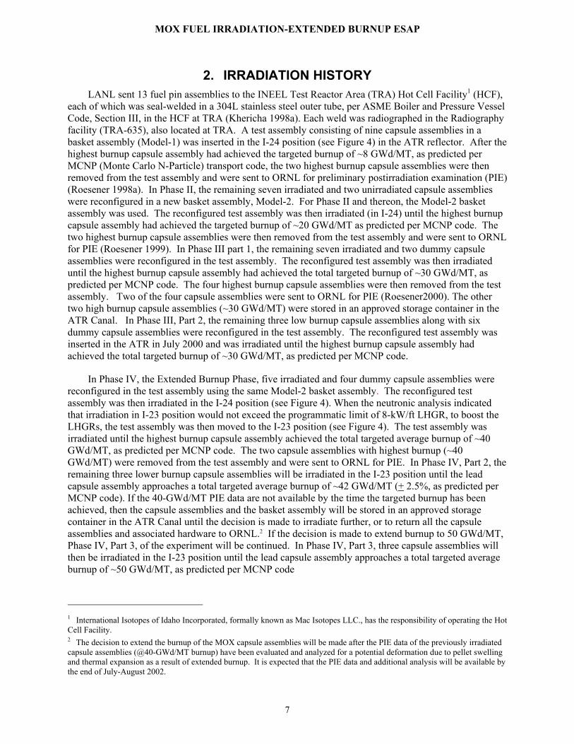
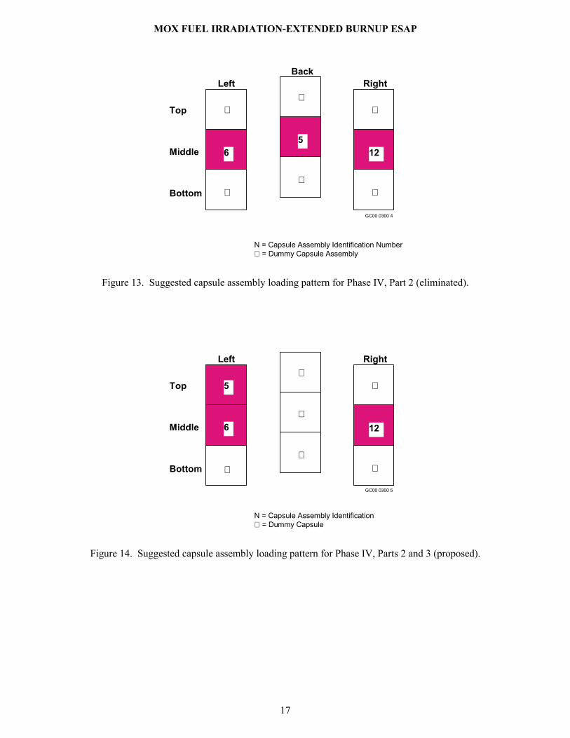
The plan was to continue irradiation using the Phase IV, Part 2, loading pattern, as shown in Figure 13. In July 2001, the INEEL decided to reconfigure the test assembly using the loading pattern for Phase IV, Part 3, as shown in Figure 14, at the end of Phase IV, Part 1. This ESAP represents the revised Phase IV, Parts 2 and 3, irradiation activities. The capsule assemblies will be irradiated until the highest burnup capsule assembly accumulates an average burnup of ~50 GWd/MT. At the end of Phase IV, Parts 2 and 3 irradiation, all of the MOX capsule assemblies, and, if desired, the remaining hardware will be sent to ORNL.
Externally, the dummy capsule assemblies are identical to the fueled assemblies, such that hydraulic flow conditions in the test assembly are not significantly affected. Each dummy capsule assembly is a solid piece of stainless steel 304L.
N = Capsule Assembly Identification = Dummy Capsule∗
6
4
∗
∗
∗
5
12
13
∗
Top
Middle
Bottom
Left RightBackBack
GC00 0300 3
Figure 12. Capsule assembly loading pattern used in Phase IV, Part 1.
MOX FUEL IRRADIATION-EXTENDED BURNUP ESAP
17
N = Capsule Assembly Identification Number = Dummy Capsule Assembly∗
∗
∗
6
∗
∗
5
∗
∗
12
Top
Middle
Bottom
Left RightBack
GC00 0300 4
Figure 13. Suggested capsule assembly loading pattern for Phase IV, Part 2 (eliminated).
5
6
∗
∗
∗
∗
∗
∗
12
Top
Middle
Bottom
Left Right
N = Capsule Assembly Identification = Dummy Capsule∗
GC00 0300 5
Figure 14. Suggested capsule assembly loading pattern for Phase IV, Parts 2 and 3 (proposed).

MOX FUEL IRRADIATION-EXTENDED BURNUP ESAP
18
4. HAZARD CLASSIFICATION The ATR and its activities have been classified as Hazard Category 1 per DOE Order 5480.23 (DOE
1992). The introduction of the MOX fuel experiments into ATR does not change the hazard classification.
The Hazard Category for the transfer of irradiated MOX capsule assemblies in Hot Cell Carrier (HCC) 3 will be verified to be Hazard Category 3 prior to shipping. Reference NFAC-OSB (1996) addresses HCC 3 for Category 3 transport between the ATR and TRA Hot Cell Facility. Preliminary hazard identifications and classifications of these types of shipments are addressed in Section 5.2 of Reference NFAC-OSB (1996). The use of HCC 3 for the MOX fuel transport in accordance per the TRA HCF safety analysis report and HCC 3 safety documentation will be confirmed prior to its use.
Hazards associated with MOX experiment materials shipped in the GE-100 and -2000 casks are maintained within the qualifications of these DOT/NRC-approved shipping containers.
MOX FUEL IRRADIATION-EXTENDED BURNUP ESAP
19
5. PROCESS DESCRIPTION
5.1 Process Flowchart This ESAP is prepared on the basis that irradiation will continue in the I-23 position. Figure shows
the expected LHGR profile as a function of EFPDs (Chang 2001). Based on this profile, it is estimated that the average LHGR for the remaining Phase IV is expected to be <6 kW/ft. However, the safety analyses are performed on the basis of LHGR of 9 kW/ft and no capsule assembly can be irradiated at or above LHGR of 9 kW/ft. Permission must be obtained from the MOX fuel project manager to irradiate any capsule assembly above 8 kW/ft (Hodge 2000a). The requirements document includes the administrative limitation that, “Prior to each fuel cycle INEEL personnel shall perform calculations that will predict the LHGR for each fuel pin as a function of time during that cycle,” e.g., see Chang 2000c. The objective is to ensure that the LHGR in each capsule assembly meets the programmatic and safety objectives.
Figure 16 shows the revised cradle-to-grave process flowchart for the MOX APT Phase IV, Parts 2 and 3, Extended Burnup Phase. For this experiment, cradle-to-grave includes assembling the experiment in the ATR Canal area (Phase IV, Part 3, loading pattern) and follows all the capsules and associated hardware items (as necessary) until they leave the TRA main gate. Section 5.2 explains in detail the steps and associated governing documents, where applicable.
5.2 Descriptions The following steps describe the cradle-to-grave process for continuing irradiation of MOX fuel
from 40- to 50-GWd/MT burnup:
Step A. Assemble the test assembly on the working tray in the Canal.
Nine capsule assemblies, three MOX fuel, and six dummy capsule assemblies will be loaded in the basket assembly per the loading pattern shown in Figure 14, on the working tray in the canal per O&MM 7.10.13.1.3, Section 4.2, Capsule and Experiment handling and Canal Loading Record. (Insert the new flux wires as per program requirements per Step E.)
Step B. Insert the test assembly in the reactor.
The experiment assembly will be loaded in the reactor I-23 location per DOP 7.2.17. Step C. Irradiate the test assembly.
The test assembly will be irradiated in the reactor. The test assembly will remain in the reactor position (I-23) until the highest-burnup capsule assembly has reached desired average burnup of ~42 GWd/MT. Preliminary depletion calculations indicate that approximately 107 EFPDs of irradiation in Phase IV, Part 2, will be required to achieve the desired burnup.
Steps D through F will be executed as needed to meet program requirements: Step D. Transfer the test assembly to the ATR Canal after a cycle. The test assembly will be removed from the I-23 reactor core position, inserted into a transfer bucket and
transferred to the canal per DOP 7.2.17.

MOX FUEL IRRADIATION-EXTENDED BURNUP ESAP
20
Step AAssemble the test
assembly on the working tray in the ATR canal.
Insert the test assemblyin the reactor.
Irradiate thetest assembly.(~42 GWd/MT)
Replace thetest assemblyflux monitors.
Insert the test assemblyin the reactor.
Repeat the steps Cthrough F as necessary.
Transfer the testassembly to the ATRCanal after a cycle.
Step B
Step C
Step E
Step F
Step G
Step D
Store the capsuleassemblies, dummy
assemblies, and basket assemblies
in the canal.
Step N
Irradiate thetest assembly.(~50 GWd/MT)
Step K
Transfer the test assembly to the
ATR canal.
Step L
Disassemble the test assembly on the working tray
in the canal.
Step OLoad the irradiated capsule assemblies,
dummy assemblies, and basket assemblies in the GE-2000 or GE-100
cask or HCC #3 cask in the canal.
01-GA50635-08
Transport the loaded GE-2000 or GE-100
cask to ORNL.
Step R
Transport the loaded HCC #3 cask to HCF.
Step P
Load the irradiated capsule assemblies,
dummy capsule assemblies, and basket
assemblies in the GE-100 cask at HCF.
Step Q
or
Transfer the test assembly to the
ATR Canal.
Step H
Insert the reconfigured test
assembly inthe reactor.
Step J
40 GWd/MTPIE results are
acceptable?
Yes
No Go toStep M
40 GWd/MTPIE data
available?
No
Yes
Store the MOXexperiment in
the canal.
Step I
Step M
Figure 15. Process flowchart for the MOX experiment, Phase IV.

MOX FUEL IRRADIATION-EXTENDED BURNUP ESAP
21
3
4
5
6
0 100 200 300 400
Effective Full Power Days During Phase IV
Pin 5
Pin 6
Pin 12Li
near
Hea
t Gen
erat
ion
Rat
e (k
W/ft
)
April 2002 November 2003
Part 2 Part 3
150
01-GA50635-10
Pin 5
Pin 6
Pin 12
Figure 16. Expected LHGRs as a function of EFPDs for Phase IV.
Step E. Replace the test assembly flux monitors.
Remove the flux wires from the test assembly in the canal and place the flux wires in the canal MOX flux wire storage bucket. The RML personnel will count flux wires in the ATR Canal. Specifically designed tools for the MOX experiment will be used. After the counting, the flux wires will be put in the canal waste stream.
Install new flux wires in the basket assembly using tools specifically designed for it, in
accordance with current methodology and using existing procedures. Step F. Insert the test assembly in the reactor.
The experiment assembly will be transferred to the reactor under existing O&MM's and inserted in the reactor location I-23 position by DOP 7.2.17.
Step G. Repeat steps D through F as necessary.
Steps D through F will be repeated until such time as neutronic burnup calculations have been shown to satisfy MOX programmatic requirements and no longer need the flux wire measurements.
If the 40 GWd/MT PIE results are not available, then execute Steps H and I.
Step H. Transfer the test assembly to the ATR Canal.
The test assembly will be removed from the reactor and transferred to the canal per DOP 7.2.17.

MOX FUEL IRRADIATION-EXTENDED BURNUP ESAP
22
Step I. Store the experiment in the canal.
The test assembly will be stored in the specifically designed and approved storage container in the canal storage area.
Steps J through L will be executed only if the PIE results of the MOX capsule assemblies with ~40 GWd/MT burnup justify the assumptions made in the safety analyses for the continuous irradiation up to ~50 GWd/MT burnup; otherwise a DAR to this ESAP will provide direction (go to Step M).
Step J. Insert the reconfigured test assembly in the reactor.
The experiment assembly will be loaded in reactor location I-23 position per DOP 7.2.17. Step K. Irradiate the test assembly.
The test assembly will be irradiated in the reactor. The test assembly will remain in the I-23 reactor core position until the lead capsule assembly has reached the desired average burnup of ~50 GWd/MT, as predicted by MCNP code. Preliminary depletion calculations indicate that approximately 330 EFPDs of irradiation in Phase IV, Part 3, will be required to achieve an average burnup of 50 GWd/MT in the highest burnup assembly (Chang 2001). (Repeat steps C through F as needed to meet program requirements.)
Step L. Transfer the test assembly to the ATR Canal.
The test assembly will be removed from the reactor and transferred to the canal per DOP 7.2.17.
Step M. Disassemble the test assembly on the working tray in the canal.
The test assembly will be disassembled on the working tray in the canal per O&MM 7.10.13.1.3, Section 4.2, Capsule and Experiment handling and Canal Loading Record. Three capsule assemblies and six dummy assemblies will be removed and placed in the specifically designed and approved MOX capsule carrier in the canal storage area.
Step N. Store the capsule assemblies and dummy assemblies in the canal.
Three capsule assemblies and six dummy capsule assemblies will be stored in the specifically designed and approved MOX capsule carrier in the canal storage area in accordance with existing ATR Canal Storage methodology and procedures. The empty basket assembly will also be stored in the canal storage area. The capsule assemblies will be stored at least 30 days after EOC, before shipping to the ORNL or the HCF.
Step O. Load three capsule assemblies, six dummy capsule assemblies and two basket assemblies into
GE-2000 cask in the canal.
The irradiated capsule assemblies (5, 6, and 12), dummy capsule assemblies, and two basket assemblies, if desired by the project, will be loaded, at least 30 days after EOC as schedule permits, into the GE-2000 cask in accordance with ATR Canal procedures, DOP 4.8.4, and cask Certificate of Compliance requirements.
If HCC 3 cask and GE-100 cask are used, steps P and Q will be executed, and additional analysis
will be provided if existing analysis is not enveloping:
MOX FUEL IRRADIATION-EXTENDED BURNUP ESAP
23
Step P. Transport the loaded HCC 3 cask to HCF.
The HCC 3 cask containing irradiated capsule assemblies will be transported to the TRA HCF per DOP 4.8.19. If three capsule assemblies are transferred in HCC3 in one shipment, then additional analysis will be provided.
Step Q. Load the irradiated capsule assemblies, dummy capsule assemblies, basket assemblies into GE-
100 cask at the HCF.
The irradiated capsule assemblies (5, 6, and 12), and, if desired, dummy capsule assemblies, and two basket assemblies will be loaded into the GE-100 cask in accordance with HCF procedures that reflect the facility’s operating requirements and cask Certificate of Compliance requirements. The basket assemblies will be cut into pieces as needed.
Step R. Transport the irradiated capsule assemblies to ORNL.
The loaded GE-100 or GE-2000 cask will be transported to ORNL per applicable DOE, DOT, and NRC requirements.
The waste generated during operations associated with this experiment is the routine solid
contaminated waste such as anti-Cs, blotter paper, etc., and liquid waste from the cask vacuum drying process (canal water). These wastes are disposed of with other contaminated waste generated during operation of the ATR. All wastes are required to have a hazardous waste determination to show if the wastes are regulated under the Resources Conservation and Recovery Act or other applicable federal regulations. This determination is performed by the generator and is then approved for inclusion in waste streams for recycling and disposal of solid wastes. Any new wastes generated from the irradiation or Hot Cell processing activities must have an approved hazardous waste determination prior to disposal of the waste to ensure the waste is placed in the appropriate waste streams.
It is written commitment of this project made by Dr. S. A. Hodge, Manager, MOX Irradiation Test Project of ORNL, that all irradiated capsules and other hardware items associated with this test (except the flux wires) will be transported to ORNL, where postirradiation examination (PIE) will be performed as appropriate (Hodge 1997a). ORNL has prepared a formal plan describing the shipments of the irradiated capsules (Shappert 1998). The INEEL has the option to dispose of the empty baskets and related hardware in Idaho if that is more cost effective, rather than shipping the material to ORNL.
There are no special requirements for facility set points or alarms in any of the above steps. The standard requirements for reactor tank and material handling are sufficient.
5.3 Safety Envelopes Steps C and K, Irradiation of fuel in the ATR
Steps A, B, D, E, F, H, I, J, L, M, and N, Canal Aactivities
The safety envelope for irradiatingon of the experiments in the ATR and ATR Canal activities is defined by the ATR Technical Safety Requirements (TSR) (TSR-186, 2001), ATR UFSAR (SAR-153, 2002), and analyses listed below.
Analysis/Requirements References Design, functional, and operational requirements
Thoms 1997a, 1997b, 2000
Grover, 1998a, 1998b, 2000a, and 2000b
MOX FUEL IRRADIATION-EXTENDED BURNUP ESAP
24
Hodge 2000a
Loading patterns/pperation schedules
Cowell 1997b, 1998b, 2000a, 2000c
Thermal-Hydraulic Ott 1998a,1998b, 2000
Ambrosek 1997, 1998, 2000
Hodge 2000b
Stress Corum 1997, 1998
Morton 1997
Hodge 2000b, Luttrell 2000
Miller (2000)
PIE results (irradiation beyond 30 GWd/MT)
30 GWd/MT - Morris (2001)
40 GWd/MT - To be provided
Shipping Roesener 1998a, 1998b, 1999, 2002
Hawkes (1998,1999a, 1999b)
For 50 GWd/MT - To be provided
ORNL performed experiments to validate the use of the FFFAP code for analyzing the thermal-hydraulics of the MOX irradiation tests (Ott 1998a and 1998b). The test flow rates and pressure gradient data are found to be in good agreement with calculated data and are acceptable (Ambrosek 1998).
The Model-2 basket was checked for vibration damage during flow testing of the Model-2 MOX test basket assembly (Ott 1998b). There were no observable changes in sound or feel (vibration) in the basket assembly (differential pressures ranging from 10 to 90 psid) such as would indicate excessive vibration. Magnetometer readings (from a cell placed outside of the assembly axially at about centerline of top dummy capsule) were acquired at each data collection point (10 psid increments); which also indicate no excessive vibration. The Model-2 basket assembly design documents have been reviewed and approved by the design review committee (Heatherly 1998, Grover 1998a).
Steps P and R - Transport of Irradiated Capsule Assemblies within TRA
The safety envelope for transportation of the irradiated MOX fuel capsule assemblies within the TRA is established by the applicable Operating Procedures, as discussed in Section 4.2, along with the controls associated with the Certificates of Compliance for the GE-100 and GE-2000 casks.
Gentillo (1992) presents an engineering evaluation of the HCC 3 cask. The internal heatup of MOX capsule assemblies has been analyzed by Hawkes (1998, 1999a, 1999b) and found acceptable relative to heat generation limits noted in Sherick (1992).
Steps O and Q Loading Activity (Cask Handling and HCF)
The safety envelope for cask handling within the ATR is established by the ATR TSR 3.5.5, Cask Handling and Irradiated Fuel Storage (TSR-186, 2001), the ATR UFSAR (SAR-153, 2002), and cask Certificates of Compliance. The loaded GE-100 and GE-2000 casks will be transported to ORNL per applicable DOE, DOT, and NRC requirements.

MOX FUEL IRRADIATION-EXTENDED BURNUP ESAP
25
The TRA Hot Cell Safety Analysis Report (SAR) and Technical Safety requirements (TSR) define the safety envelope for the TRA HCF. The GE-100 cask at the TRA HCF will be loaded in accordance with HCF procedures that reflect the facilities operating requirements and cask Certificate of Compliance requirements. The loaded cask will be transported to ORNL per applicable DOE, DOT and NRC requirements.
The internal heatup of MOX capsule assemblies in the shipping cask will be analyzed prior to shipment when the decay heat rates become available and confirmed to meet shipping cask requirements prior to shipment. It is expected that the results will be bounded by the previous analysis, Hawkes (1998, 1999a, 1999b).

MOX FUEL IRRADIATION-EXTENDED BURNUP ESAP
26
6. DEMONSTRATION OF COMPLIANCE This section shows compliance with the ATR TSR/UFSAR requirements that are to be met. Table 2
shows compliance with the safety envelope.
Table 2. Demonstration of compliance. ALL EXPERIMENTS6
Requirement Compliance TSR 3.5.5 Cask Handling and Irradiated Fuel Element Storage
Cask Handling and Irradiated fuel element storage shall be per Table 3.5.5-1
Cask handling at TRA is performed using Detailed Operating Procedures (DOP). These DOPs ensure compliance with all requirements: 2.1.19, 7.8.25, 4.8.4, 4.8.7, 4.8.19, 4.8.36, and 4.8.46. Note: DOP 4.8.4 applies to the GE 2000 cask and DOP 4.8.36 applies to the GE 100 cask. These DOPs include information that demonstrates acceptable cask weights.
TSR 3.9.1 Experiment Safety Margin An experiment safety assurance package (ESAP) shall demonstrate compliance to the ATR plant protective criteria for condition 1, 2, 3, and 4 faults.
Addressed in Section 7 of this ESAP.
TSR 4.9.1.1 Surveillance Requirement Verify reactor performance calculation prior to reactor operation after core changes and prior to planned operation changes not within the existing reactor performance calculation.
The current Core Safety Analysis Package (CSAP) demonstrates compliance with “plant response to reactivity additions” requirement.
TSR 4.9.1.3 Surveillance Requirements Verify ESAP prior to experiment insertion into the reactor vessel and prior to scheduled startup for experiments in the reactor vessel, or prior to experiment or irradiation test material insertion in the canal.
DOPs 7.2.17, 7.2.1, 4.8.4, 4.8.7 and 4.8.46, ensure compliance with all requirements.
TSR 5.7.7 Nuclear Criticality Safety TSR 5.7.7.2 Fuel storage and handling shall meet the following requirements: a. Allowable fissile material forms in the ATR facility shall be
limited to: 3. Miscellaneous fissile material specimen containing equivalent
of ≤365 grams of U-235 (e.g., capsule EXPERIMENTS, flux monitors, and sources).
b. Fissile material shall be stored in APPROVED FUEL
STORAGE that is subject to the following limits: 1. keff shall not exceed 0.95 for the service condition. 2. Cooling shall be adequate to remove decay heat without
reaching saturation temperature in the coolant. 3. Storage shall be stable and not susceptible to tipping from
credible natural phenomena or work activities. 4. Relocation of storage units shall be completed only when
fissile materials have been removed from the unit (Carriers for transporting the material forms and shipping containers
All irradiated experiment movements are controlled by DOPs and O&MMs that specify all handling limits and requirements (DOP 7.8.25, O&MM 7.10.13.1.2, 7.10.13.1.3, and 7.10.13.1.4). Each unirradiated capsule assembly contained 4 g of Pu and 0.2 g of U-235. Therefore, the test assembly contains ~12 g of Pu plus <1g of U-235 based on three MOX fuel capsule assemblies. ATR TSR conservatively considers 1 g of Pu equivalent to 2 g of U-235. Thus, with the equivalent of less than 25 g of U-235, the MOX test assembly meets the requirement. The MOX experiment, as assembled for irradiation in the ATR, is composed of a maximum of 3 MOX capsules. Each capsule includes 4 g of weapons grade Pu and <0.2 g of U-235. Therefore, the maximum U-235 equivalent mass, enveloping all MOX experiment activities in the ATR facility, would be ~25 g. This MOX experiment U-235 equivalent mass is considerably below the TSR limit of 365 g for miscellaneous fissile material specimens. Under optimum water moderation and reflection conditions, a
6 ORIGEN2 isotopic inventory analysis for 30 GWd/MT burnup indicates that there would be ~1 gm Pu and <0.1 gm U235 per capsule (Terry 2000).

MOX FUEL IRRADIATION-EXTENDED BURNUP ESAP
27
Requirement Compliance for unirradiated fissile material forms that are APPROVED FUEL STORAGE are exempt from this limit.)
5. Storage shall be located away from areas where heavy loads are routinely handled (e.g., crane assisted activities) or specific limitations shall be established to preclude physical contact between heavy loads and materials in storage.
homogeneous U-235 mass of at least approximately 500 g would be required to produce a k-effective of 0.9 (corresponding minimum mass of Pu-239 for the same k-effective would be approximately 300 g). The k-effective for any arrangement of the 3 MOX capsules is bounded by the 11 MOX capsules analysis in the ATR Canal and is assured to be <0.95, as long as other fissile material forms are maintained at the TSR required distance of at least 1 ft from the MOX capsules. Ryskamp (1997), Boston (1998). Adequate decay heat cooling is demonstrated in Compliance statements for UFSAR 10.4.3 and 10.3.5.2.1 (Grover 1998b).
TSR 5.7.7.2 Continued Applicability
Applies at all times except as specified for fissile material forms outside of APPROVED FUEL STORAGE (TSR 5.7.7.2(d)). Miscellaneous fissile material specimens containing in aggregate the equivalent of <15 g of U-235 (e.g., experiments, flux monitors, and sources) are excluded from and/or do not to show compliance with these requirements.
The MOX experiment basket, as supported and handled, is stable and not susceptible to tipping. The MOX capsule carrier, which infrequently stored as many as 11 MOX capsules, is also stable and designed to prevent spilling capsules if tipped. The MOX capsule carrier is approved for storage for MOX capsules and is exempt from this requirement (b.4). The MOX capsule carrier may be relocated, as necessary, to accommodate MOX capsule manipulations. Existing ATR Canal procedural controls will assure the MOX experiment basket or MOX capsule carrier will be stored as required. All irradiated experiment movements are controlled by DOPs and O&MMs that specify all handling limits and requirements (DOP 7.8.25, O&MM 7.10.13.1.2, 7.10.13.1.3, and 7.10.13.1.4). Requirements 1, 2, and 3 of this section are met for two MOX capsules in HCC 3. If needed, two MOX capsules will be transferred in HCC 3 to the TRA Hot cell facility to ship to the ORNL. Two capsules located in the isotope transport canister within HCC 3, following at least 30 days decay after reactor shutdown, meet the requirements for being in approved fuel storage. The above compliance for Item 1 shows that k-eff for only two MOX capsules is less than 0.95. Hawkes (1999a, 1999b) shows adequate cooling of two MOX capsules in the HCC 3 at the end of Phase I irradiation after 30 days of cooling. If MOX capsules will be transferred in HCC 3 to the TRA Hot cell facility at the end of the irradiation, additional analysis will be provided if existing decay heat analysis is not enveloping.
TSR 5.7.7.2 Continued d. Fissile material forms outside of APPROVED FUEL STORAGE shall be limited to (limits apply to each independently):
1. Canal
All irradiated experiment movements are controlled by DOPs and O&MMs that specify all handling limits and requirements (DOP 7.8.25, O&MM 7.10.13.1.2, 7.10.13.1.3, and 7.10.13.1.4).

MOX FUEL IRRADIATION-EXTENDED BURNUP ESAP
28
Requirement Compliance ii. No more than one fueled EXPERIMENT. Miscellaneous fissile material specimens containing in an aggregate the equivalent of <15 g of U-235 (e.g., EXPERIMENTS, flux monitors and sources) are excluded from this requirement. iii. No more than 365 g of U235 equivalent in miscellaneous specimen. iv. No more than one type (FUEL ELEMENT(S), fueled LOOP FACILITY EXPERIMENT or miscellaneous fissile material specimens) of fissile material shall be out of approved storage at any time. Miscellaneous fissile material specimens containing in an aggregate the equivalent of <15 g of U-235 (e.g., EXPERIMENTS, flux monitors and sources) are excluded from this requirement.
2. Vessel
ii. No more than one fueled EXPERIMENT outside the core. Miscellaneous fissile material specimens containing in an aggregate the equivalent of <15 g of U-235 (e.g., EXPERIMENTS, flux monitors and sources) are excluded from this requirement.
iii. No more than 365 grams of U-235 equivalent in miscellaneous specimen.
iv. No more than one type (FUEL ELEMENT(S), fueled LOOP FACILITY EXPERIMENT or miscellaneous fissile material specimens) of fissile material shall be out of approved storage at any time. Miscellaneous fissile material specimens containing in an aggregate the equivalent of <15 g of U-235 (e.g., EXPERIMENTS, flux monitors and sources) are excluded from this requirement.
ii. The MOX experiment basket and the MOX capsule carrier, stored on a canal hook, are approved fuel storage for MOX capsules. iii. The U-235 equivalent mass of 3 MOX capsules is 25 g. iv. Existing procedural controls will ensure that no other fissile material form will be out of approved storage in the canal when MOX capsule manipulations are performed on the capsule-loading tray. All irradiated experiment movements are controlled by DOPs and O&MMs that specify all handling limits and requirements (DOP 7.8.25, O&MM 7.10.13.1.2, 7.10.13.1.3, and 7.10.13.1.4). ii. The MOX experiment in the designated reactor I-hole is considered approved storage. Existing procedural controls will ensure that no other fueled experiment in the vessel is outside the core whenever the MOX experiment is being handled in the vessel. The MOX experiment basket includes a maximum of 3 MOX capsules, which represent a U-235 equivalent mass of less than 25 g. Existing procedural controls will assure that no other fissile material form will be out of approved storage in the vessel when the MOX experiment basket is being handled in the vessel.
TSR 5.7.7.2 d Continued 3. Other ii. No more than one fueled EXPERIMENT outside the canal or
the reactor vessel. Miscellaneous fissile material specimens containing in an aggregate the equivalent of <15 g of U-235 (e.g., EXPERIMENTS, flux monitors, and sources) are excluded from this requirement.
iii. No more than 365 g of U-235 equivalent in miscellaneous specimen outside the canal or the reactor vessel.
iv. No more than one type (FUEL ELEMENT(S), fueled LOOP FACILITY EXPERIMENT or miscellaneous fissile material specimens) of fissile material shall be out of approved storage at any time. Miscellaneous fissile material specimens containing in an aggregate the equivalent of <15 g of U-235 (e.g., EXPERIMENTS, flux monitors and sources) are excluded from this requirement.
All irradiated experiment movements are controlled by DOPs and O&MMs that specify all handling limits and requirements (DOP 7.8.25, O&MM 7.10.13.1.2, 7.10.13.1.3, and 7.10.13.1.4). Existing procedural controls will assure no other fueled experiment is outside the canal or reactor when the MOX capsules are shipped from the canal. The MOX experiment basket includes a maximum of 3 MOX capsules, which represent a U-235 equivalent mass of less than 25 g. Existing procedural controls will assure that no other fissile material form will be out of approved storage when the MOX experiment basket is being handled.
TSR 5.7.7.2 Continued e. In water, a minimum distance of one foot shall be maintained between any two of the individual items of fissile material forms outside APPROVED FUEL STORAGE, except for special circumstances during loading and unloading of FUEL ELEMENTS from the fuel annulus. When tolerance or other interferences do not allow loading or unloading of a single FUEL ELEMENT from the fuel annulus, a pair may be inserted or removed provided the SRO in charge of handling has completed a specific evaluation that establishes limits to preclude interaction with any other fissile material out of APPROVED STORAGE.
All irradiated experiment movements are controlled by DOPs and O&MMs that specify all handling limits and requirements (DOP 7.8.25, O&MM 7.10.13.1.2, 7.10.13.1.3, and 7.10.13.1.4). MOX experiment capsules constitute one fissile material form and therefore may be adjacent to one another provided no other fissile material form is within 1 foot from any of the MOX capsules.

MOX FUEL IRRADIATION-EXTENDED BURNUP ESAP
29
Requirement Compliance Miscellaneous fissile material specimens containing in an aggregate the equivalent of <15 g of U-235 (e.g., EXPERIMENTS, flux monitors and sources) are excluded from minimum distance requirements.
TSR 5.7.7.2 Continued f. All activities requiring movement of fissile materials to be out of APPROVED FUEL STORAGE shall be completed with at least two staff members trained in the handling of fissile material. In addition, the Shift Supervisor or his designated alternate shall be present to direct fuel handling when more than two FUEL ELEMENTS are outside approved storage in the canal including canal transfer tube. Activities requiring movement of miscellaneous fissile material specimens containing in an aggregate the equivalent of <15 g of U-235 (e.g., EXPERIMENTS, flux monitors and sources) shall be completed with at least one staff member trained in handling of fissile material.
All canal operators dealing with operations involving the MOX capsules will be trained and certified fissile material handlers. The two-man rule will be invoked by S.D. 11.5.6 and O&MM 7.10.13.1.27.
TSR 5.8.3 Reviews and Audits A contractor-designated, independent review committee shall review all matters with nuclear safety implications. The membership, responsibilities, and procedures of the review committee shall be formally documented and approved by contractor management.
The Safety and Operations Review Committee (SORC) reviews all Experiment Safety Assurance Packages per SP 10.1.1.3.
UFSAR 4.3.2.2 Power Distribution Due to the nature of ATR operation new experiments are occasionally inserted into the reactor. When new experiments are placed into the reactor, additional analysis is performed to provide assurance that the reactor response with new experiments meets the established safety envelope.
MOX experiment does not require additional analysis, since the experiment is irradiated in the small I-hole (I-24 or I-23) position. Experiments located in the I-24 or I-23 position have no significant effect on the ATR axial flux profile in the reactor fuel.
UFSAR 10.1.7.1 Primary Experiment Safety Analyses Criterion
The consequences of normal operation of the experiment and of any experiment fault must be bounded by the ATR Plant Protection Criteria for the same operating condition [i.e., Condition 1, 2, 3, and 4, as defined in Chapter 15 (Accident Analyses)]. The primary experiment safety analyses criterion applies whenever the experiment is within the ATR facility.
Compliance to this requirement is demonstrated in Section 7 and 8 of this ESAP. Faw (1998) concluded, based on ORIGEN 2 and RSAC-5 calculations, that the MOX fuel would contribute less than 0.1% of the total dose at the LPZ (low population zone) if a postulated large break resulted in a release of radionuclides from both the ATR fuel and the MOX fuel. Based on a postulated confinement leak rate of 100% day, Faw calculated LPZ doses from MOX fuel of only 0.210 rem thyroid and 0.0132 rem EDE. Faw used the maximum fission product inventory in his analysis. See Terry (1998b) for clarification of table headings in Faw (1998) reference.
UFSAR 10.1.7.2 General Experiment Safety Analyses Criterion for Experiments Containing Fissile Material
The following general experiment safety analyses criterion must be met for any experiment containing fissile material:
The experiment fissile material form and content must be shown to be enveloped by the existing criticality safety evaluations described in Chapter 9 (Auxiliary Systems) and the TSR administrative controls for nuclear criticality safety.
This general experiment safety analyses criterion for experiments containing fissile material applies whenever the experiment is within the ATR facility. If this criterion is not met, additional
At most, there will be three MOX capsules in the canal at any one time. This would represent less than 25 g of U-235 equivalent. Per UFSAR 9.1.2.1, “Fissile material units, except ATR elements and loop experiments, are limited to ≤365g U-235 equivalent (plus ≥1 foot spacing) so that k-effective need not be considered.” Experiment manipulations involving the MOX capsules are addressed by existing procedural controls
hi h ill h i i li f l i f

MOX FUEL IRRADIATION-EXTENDED BURNUP ESAP
30
Requirement Compliance criticality safety evaluations and appropriate changes to the TSR administrative controls must be made prior to conducting the experiment.
which will assure the criticality safety evaluations of Chapter 9 are enveloping. Administrative controls for nuclear criticality safety are addressed under TSR 5.7.7, contained in this section.
UFSAR 10.1.7.3.2 Code Compliance of Experiment Containment
Experiment containment that holds pressure greater than 235 psig, or contains material that can generate pressure pulses greater than 430 psig, must have a design that meets the intent of ASME Section III, Class 1 standards, or the ability, demonstrated by prototype testing or other means, to withstand service conditions without failure.
Each capsule assembly has been designed as a Class 1 vessel and satisfies the appropriate rules specified in subsection NB, Section III, Division 1 of the ASME B&PV Code. Based on the 11% fission gas release fraction, Hodge (2000b), MOX capsule assembly pressure is calculated to be 136 psia (for 50 GWd/MT), which is less than 235 psig.
UFSAR 10.1.7.3.3 Containment of Materials Materials incompatible with the reactor fuel element cladding, the reactor primary coolant, canal water coolant, or with reactor primary coolant system (PCS) structural materials must be contained to ensure they are not released to the PCS or canal as a result of a Condition 2 or 3 fault. Incompatible materials, normally used as activation monitors, must be secured to minimize the likelihood of being lost in the reactor PCS.
All materials associated with the MOX experiment assembly are compatible with the primary coolant and/or with the PCS structural materials. Gallium (about 2 ppm) in the fuel pellets, is inside Zr-clad, which in turn is encapsulated in a stainless steel pressure vessel that meets ASME Section III code requirements. Gallium will not migrate to the stainless steel capsule. The MOX experiment does not have any small parts, such as tabs, that can break off and get into the reactor system. Standard ATR flux monitor wires will be contained in an aluminum holder tube and secured in the basket assembly.
UFSAR 10.1.7.3.4 Excluded Materials The following materials are not permitted in an experiment or loop facility within the reactor biological shielding. Unknown Materials - No experiments shall be performed unless the material content, with the exception of trace constituents, is known.
Explosive materials with an equivalent of ≥25 mg of TNT. (Explosive material is a solid or liquid which has an explosion hazard in water or steam, as defined in Lewis (1990), and is used in a configuration that can detonate and produce a shock wave.) Cryogenic liquids
Materials contained in this experiment are identified via Wachs 1997 (listing of Drawings is provided in the Reference) of this ESAP. Chidester 1998 presents the uranium and plutonium loadings. Gallium (about 2 ppm) is present in the fuel pellets, which is inside Zr-clad, which in turn is encapsulated in a stainless steel pressure vessel that meets ASME Section III code requirements. This experiment contains no explosive materials. This experiment contains no cryogenic materials.
UFSAR 10.1.7.3.5 Evaluation of Materials The following materials are not used in experiments unless such usage is shown to be in compliance with the primary experiment safety analyses criterion in section 10.1.7, and the compliance analyses are completed prior to insertion in the reactor vessel or canal. Radiologically hazardous activation products. Radiation sensitive materials. Highly flammable or toxic materials, per se or as by-products of radiation sensitive materials. Reactive Materials which are defined as any solid or liquid which has a reactivity index of 2 in National Fire Protection Association Publication 704 (NFPA 1996) or has a disaster or fire hazard indicating detrimental reactions in water or steam (Lewis 1990).
The containment, irradiation monitoring, shielding, and operational controls are adequate for the material content of this experiment. Section 8 of this ESAP presents the detailed Safety Analysis for Radiation exposure and Barrier Protection. The experiment contains uranium and weapons grade plutonium. Peak total activity from the actinides + daughter and other fission products (MOX fuel) is calculated to be considerably less than the total activity from the actinides + daughter and other fission products (ATR fuel) generated during normal ATR fuel cycles (Hodge 1997c). Note that the total activity of a MOX capsule decreases as burnup increases (Terry 1998c, 1999, 2000) Wilson (1997) states that intermetallic compound formation is the principal interaction mechanism between zircaloy and gallium. This interaction is very limited by the low mass of gallium (about 2 ppm), so

MOX FUEL IRRADIATION-EXTENDED BURNUP ESAP
31
Requirement Compliance problems are not expected with the zircaloy cladding. The stainless steel will not interact with gallium because no gallium will migrate through the zircaloy.
UFSAR 10.1.7.3.6 Failure of common systems The failure of systems that are common to both the experiment facilities and experiments and to the plant will not cause interactions (from this common use) that result in total consequences exceeding those specified by the IPT Protection Criterion in Section 10.2.6.1 and ATR Plant Protection Criteria discussed in Chapter 15 (Accident Analyses) for Conditions 2, 3, and 4.
There is no such common system to MOX experiment and the plant.
UFSAR 10.1.7.3.7 Physical Layout Components of experiment facilities are located and oriented to preclude physical interference with personnel evacuation or with safety-related systems, structures, and components. If displacement of system shielding is involved, measures are to be taken to ensure radiation levels are below the ATR Plant Protection Criteria for occupational exposure.
The test assembly is inserted in a small I-hole position I-23, thus precluding physical interference with reactor components. No displacement of reactor shielding is involved.
UFSAR 10.1.7.4 Thermal Hydraulic Criterion The conduct of the experiment must not adversely affect decay heat transfer from the canal fuel elements or heat transfer from the PCS.
While in the core, this experiment is in an existing irradiation facility away from fuel elements. While in the canal, it will be located on a canal hook, on the capsule loading tray, or in a specially fabricated carrier, away from the fuel storage grids. Conduct of the experiment will not adversely affect decay heat transfer from the canal fuel elements or heat transfer from the PCS.
UFSAR 10.1.8.1 Quality Review The design, fabrication, testing, and material content of all contractor-supplied experiment hardware are verified in accordance with the contractor's Quality Program Plan (See Chapter 17, Quality Assurance). For experiment hardware supplied by other organizations, the design, fabrication, testing and material content are verified in accordance with a Quality Program that has been reviewed by the contractor and found to meet the intent of the applicable sections of the contractor Quality Program Assurance or the contractor verifies that the experiment meets the intent of the applicable sections of the contractor Quality Program Assurance. These quality reviews are documented in the ESA.
ORNL and LANL performed the design, fabrication, testing, and verification of material content. The documentation associated with these activities has been reviewed for compliance with requirements by INEEL: Ambrosek 1998, 2000; Morton 1997; West 1997a, 1997b; Miller 2000; Wachs 1997. The ORNL and LANL quality programs were reviewed by INEEL and meet the applicable requirements (Cooper 1997). Fabrication, testing, and material content of the ORNL and LANL-supplied components have been reviewed by Quality (Cooper 1998) and are acceptable. For Model-2 basket assembly, see nonconformance report (NCR 1998) and Hodge (1998)
UFSAR 10.1.8.2 Supporting Analyses The contractor is responsible for the adequacy and accuracy of supporting analyses submitted by the experimenter organizations. The operation of each experiment facility is compared with the facility design specification to ensure that it is properly enveloped. Each experiment is compared to the safety analysis envelope to ensure consistency with the assumptions made in the analyses.
The analyses in support of this experiment were performed by ORNL: Corum (1997, 1998), Ott (1998a, 1998b, 2000), Hodge (1997b, 1997c, 2000b), Thoms (1997a, 1997b), Luttrell (2000); LANL: Chidester (1998); and INEEL: Ambrosek (1997), Bayless (1998), Boston (1998), Chang (2000a, 2000b, 2000c), Faw (1998), Hawkes (1998, 1999a, 1999b), Khericha (1998a), Pedersen (1998b), Roesener (1998a, 1998b, 1999, 2000), Terry (1998a, 1998b), and Tomberlin (1997). INEEL Ambrosek 1998, 2000; Morton 1997; West 1997a, 1997b; and Miller 2000 reviewed the ORNL analyses for adequacy and accuracy (including assumptions to the supporting analyses).

MOX FUEL IRRADIATION-EXTENDED BURNUP ESAP
32
Requirement Compliance UFSAR 10.1.8.3 Independent Safety Review
Each ESAP has an independent safety review. A Contractor-designated, multi-disciplined independent safety review committee reviews each experiment and the analyses used to verify compliance to this UFSAR and the TSR, and presents recommendations to the Reactor Programs Director. The independent safety review committee concurs with conducting the experiment. The independent safety review committee keeps records of the review for each experiment or class of experiments.
This ESAP has been presented to and approved by SORC.
UFSAR 10.4.3 Experiment Handling Evaluations For fueled experiments, a minimum cooling time after shutdown will be established to assure that melting of the experiment will not occur during handling of the experiment. For loop experiments, a minimum cooling time after shutdown of 8 hr has been established (Hendrickson 1997a). If necessary, a shorter time may be supported by the ESA.
Ambrosek 1997 analysis for 8 GWd/MT burnup states that a horizontal MOX capsule on the canal floor 4 hr after ATR shutdown will not boil on the capsule surface, which precludes any potential for dryout and a temperature excursion. Note that the fission product inventories/decay heat rate decreases with burnup (Terry 1998, 1999, 2000). Therefore, the Ambrosek analysis is bounding for burnups higher than 8 GWd/MT. The MOX assembly has no reverse flow device to hinder natural convection. Natural convection cooling in the MOX assembly is expected to be better than in an ATR fuel element because a large portion of the operational pressure drop is across an orifice. Therefore, MOX fuel melting will not occur in the canal. Restrictions will be placed in the Reactor Loading Record to prohibit transfer of the test assembly out of the reactor and to the canal in less than 4 hr after a reactor scram.
UFSAR 10.4.3 Experiment Handling Evaluations (cont.) The ESA addresses a) handling operations which can include assembly, disassembly, storage, and cask handling, b) limiting fault analyses for each handling evolution, and c) effects on the experiment during a canal draining accident and demonstrates compliance with the ATR Plant Protection Criteria for all applicable operating conditions.
The demonstration of compliance with the ATR Plant Protection Criteria for all applicable operating conditions is addressed in Section 8, Plant Protection Criteria, of this document. c) Thermal calculations for an irradiated MOX capsule cooled by natural convection of ambient air (as would be encountered in a drained canal) show that a canal draining event beginning 4 hr after reactor scram would result in no melting of any fuel or structural material in the test assembly (Bayless, 1998).
UFSAR 10.4.3 Experiment Handling Evaluations (cont.) Various experiment handling evolutions require the use of building cranes. Formal documentation shall be available to show limits for each crane used. The document shall indicate load limits, lift heights, allowable reactor status (e.g., operating, shutdown, or defueled) and allowable status of canal storage. Verification of the required documentation is an element of the ESA.
DOP 4.8.4, which applies to the GE 2000 Cask, DOP 4.8.36 which applies to the GE 100 Cask, or DOP 4.8.7 which applies to the HCC 3 Cask, shall be used when experiment handling requires its use for the MOX experiment. These casks have been approved for ATR and the corresponding DOP references the requirements of this section of the UFSAR.
CAPSULE EXPERIMENT ONLY
UFSAR 10.1.5 Classification of Experiment Structures, Systems, and Components (SSC)
Classification of the capsule and canal experiment SSC and the applicability of General Design Criterion 70 to capsule experiment SSC are addressed on a case basis in the ESA for the capsule.
No important-to-safety SSC for this capsule experiment need to meet General Design Criterion 70. Experiment fault consequences are consistent with those of the reactor and its associated systems.

MOX FUEL IRRADIATION-EXTENDED BURNUP ESAP
33
Requirement Compliance UFSAR 10.3.5.1.1 Comparison to Safety Analyses (Reactivity
Insertion Rate) The potential reactivity insertion rate shall not exceed the reactivity insertion rate of the limiting event in each fault category analyzed in the UFSAR without additional analyses to show acceptable consequences. Verification of compliance is required prior to reactor operation.
The potential reactivity insertion from experiment failure is within the reactivity limits for the fault categories as discussed in Section 7.
UFSAR 10.3.5.1.2 Flux Trap Cascading Experiments in a reactor flux trap that generate significant heating and transfer the heat to the associated coolant very rapidly have the capability of adding additional positive reactivity during a power transient. This effect is known as cascading. Analyses in Chapter 15 (Accident Analyses) establish a reactivity insertion envelope for this effect. The cascading reactivities used in Chapter 15 were developed from the previous analyses of a 0.75$ step insertion (EG&G 1994b). The cascade reactivity envelope as defined in Chapter 15 is 0.05$ in 0.13 seconds for Condition 2 events, 0.03$ in 0.04 seconds for Condition 3 events and 0.17$ in 0.15 seconds for Condition 4 events.
This experiment is not located in a flux trap.
UFSAR 10.3.5.1.3 Flux Trap Reactivity Feedback The positive reactivity feedback from the flux traps was considered significant in the analyses of the PCS flow coast down event during a loss of commercial power (Chapter 15.3, Decrease in Reactor Primary Coolant Flow Rate) (Terry 1994). The reactivity feedback from the flux traps shall not exceed the values of the analyses without additional analyses to demonstrate compliance with the plant protection criteria. The verification of the reactivity feedback must be completed prior to reactor operation.
This experiment is not located in a flux trap.
UFSAR 10.3.5.2.1 Experiments Cooled by Reactor Primary Coolant
During reactor operation in the pressurized mode with reactor power greater than 3 MW, when reactor primary coolant is used to cool surfaces of experiments, the following thermal-hydraulic criteria are used to assure no flow instability occurs during normal transient conditions: (i) The DNB ratio is always greater than two; or the heat flux at the hottest spot is lower, by at least three standard deviations, than the DNB heat flux computed for the condition of reactor primary coolant pumps coast down to emergency flow assuming reactor power is initially 250 MW and a PPS scram occurs. (ii) The rise in bulk reactor primary coolant temperature along the experiment hot track is less than half the value that would cause flow instability; or the highest reactor primary coolant temperature is lower, by at least three standard deviations, than the value that would cause the flow to become unstable, computed under the same condition as (i) above. (iii) Any perturbation by an experiment of reactor primary coolant flow in a fuel element shall not cause the protection criteria of Chapter 15 (Accident Analyses) to be exceeded. Verification of the thermal hydraulic criteria is required prior to reactor operation.
The thermal analysis for two pump operation presented in Ott (2000), results in the following: DNBR Flow Instability Ratio 5.6 (>2.0) 3.85 (>2.0) Limits are given in parenthesis These values were calculated for coastdown of the primary system scenario as a result of loss of commercial power to the site during two pump operation with SW lobe power at 60 MW, which is the maximum allowable lobe power for the SW lobe.
(iii) No credible mechanisms have been identified by which this experiment could possibly perturb the coolant flow in a reactor fuel element.
UFSAR 10.3.5.3. Gas Leakage During reactor operation, experiments must not leak gas into the reactor such that the ATR Plant Protection Criteria specified in Chapter 15 (Accident Analyses) are exceeded.
Gas release potential from this MOX experiment is limited to the helium and generated fission product gases. The peak fission product gas volume from 9 capsule assemblies was estimated to be small (1.8 cubic in.), such that if all was

MOX FUEL IRRADIATION-EXTENDED BURNUP ESAP
34
Requirement Compliance released simultaneously, it would not exceed the consequences of a gas leakage fault as discussed in UFSAR Section 15.10.4. Note that in Phase IV, only five capsule assemblies will be irradiated. In addition, these few cubic inches of gases would be swept through the PCS and largely dispersed before potentially entering ATR fuel or flux traps. Each capsule assembly has been designed as a Class 1 vessel per the appropriate rules as specified in subsection NB, Section III, Division 1, of the ASME B&PV Code. Therefore, leakage from a capsule is a Condition 3 fault. Based on the 11% fission gas release fraction, Hodge (2000b), MOX capsule assembly pressure is calculated to be 136 psia (for 50 GWd/MT), which is less than the normal core inlet pressure of about 360 psig.

MOX FUEL IRRADIATION-EXTENDED BURNUP ESAP
35
7. SAFETY ANALYSIS The ESAP is for irradiation of the MOX experiment in the reactor I-23 position until the highest
burnup capsule assembly achieves the targeted average burnup of ~50 GWd/MT. Irradiation in any other location than I-23 or I-24 position will require revision of this ESAP. The results of the analyses discussed in this section are based on the Model-2 basket assembly.
7.1 Verification of ASME B&PV Code Requirement for Stainless Steel Capsule
The 304L stainless steel capsule assembly for each fuel pin assembly is designed to meet ASME Boiler and Pressure Vessel Code, Section III, requirements. For the loading conditions considered in these analyses, it was determined that ASME Section III, 1998 and 1995 editions with addenda through 1996, have the same requirements. The capsule is subject (in the event of fuel pin failure) to internal pressure loads caused by the fission gas release at elevated temperatures, external pressure load caused by ATR primary coolant water pressure, and thermal loads caused by heat generation. There is no appreciable external load on the capsule. Luttrell (2000) evaluated the stresses in the stainless steel capsule for the design conditions identified by Thoms (2000). Similarly, Luttrell (2000) evaluated the basket assembly, which holds nine capsule assemblies during irradiation, for its ability to withstand the maximum possible pressure differential. The results for the capsule and the basket assembly are found to be satisfactory, and are verified by Miller (2000).
7.2 Irradiation of the Experiment in the ATR Steps C and K, Irradiation of fuel in the ATR
The following Condition 1, 2, 3, and 4 scenarios were analyzed on the basis of nine MOX fuel capsule assemblies in the test assembly. Note that three or fewer MOX fuel capsule assemblies will be loaded and irradiated in the test assembly at any time. The INEEL reviewed the analyses and results and found them satisfactory (Ambrosek 2000).
7.2.1 Condition 1, Normal Power Operation in the Reactor Fission Gas Behavior and Swelling Effects When ceramic nuclear fuel pellets are irradiated, they are subject to dimensional changes caused by
two major phenomena: densification and swelling. Fuel densification and swelling result from the combination of two components:
• Thermal effects cause expansion of the materials and coalescence of the initially contained voids, which results in densification of pellets.
• Accumulation of fission products with volumes greater than the atoms from which they are born causes swelling of pellets.
Fuel swelling results from the combination of two major phenomena:
• Swelling of solids occurs when fission products of greater combined volume replace the fissioned uranium and plutonium atoms from which they are born
• Swelling of gases occurs when the fission gases and some volatile fission products form microbubbles in and around the ceramic grains and exert pressure on the internal structure of the pellets.

MOX FUEL IRRADIATION-EXTENDED BURNUP ESAP
36
The MOX fuel pins have been designed with a diametral gap of 0.002 to 0.0035 in. (2.0 to 3.5 mils) between the MOX pellets and the Zircaloy-4 cladding (Heatherly 1998). The stainless steel capsules have been designed with a diametral gap of 0.002 to 0.003 in. (2.0 to 3.0 mils) between the Zircaloy-4 cladding and inner wall of the stainless steel capsule (Heatherly 1998). If the radial growth of the pellets under irradiation exceeds the widths of these initial gaps, undue stress could be generated in the fuel pin cladding and/or the stainless steel capsule itself. In addition, dimensional expansion of the pellets can reduce the volume available for fission product gases, and thereby increase the internal pressure of the fuel pins. Note that some relaxation will occur as a result of dimensional expansions in the Zircaloy-4 cladding and stainless steel capsule.
The following paragraph demonstrates that the MOX capsule assemblies can tolerate such dimensional changes without increasing risk to the ATR operation. The analyses were performed using the CARTS7 code, and the results verified against hand-calculations.
The fission gas inventory comprises krypton (Kr), xenon (Xe), iodine (I), and cesium (Cs). Cs and I originate as independent elements, but subsequently combine to form such gas molecules as I2 and CsOH, and compound CsI, which is also a gas at high temperature. As these gases accumulate within the fuel matrix, a portion of the total gas inventory will emerge from the pellet surface and enter the voids within the confines of the surrounding fuel pin assembly. This escape of fission gases from the fuel pellets pressurizes the fuel pin assembly. The escape fraction depends upon atomic diffusion, gas bubble nucleation, bubble migration, bubble coalescence, interaction of bubbles with structures, and irradiation resolution.
The fission gas-escape-fraction data for MOX fuel reported in the literature indicate that the gas release fraction depends on LHGR and total burnup. Figure 17 present the fission gas release fraction as a function of LHGR for the burnup between 30 to 50 GWd/MT [produced from Table 3.1 of Hodge (2000b)]. The figure shows that the release fraction increases as LHGR increases for the accumulation of 30- to 50-GWd/MT burnups. Therefore, from Figure 17, the maximum expected fission gas release fraction for a LHGR of 9 kW/ft would be 11% for burnup between 30 to 50 GWd/MT. For low LHGRs, release fractions remain very low, even for a burnup up to 60 GWd/MT, as seen in Figure 18 [produced from Table 3.2 of Hodge (2000b)]. For an LHGR of 4.1 kW/ft and 50-GWd/MT burnup, Westinghouse provided a best-estimate value of 1.9% release fraction for the proposed PDR600 MOX fuel.
The PIE analyses were performed on MOX fuels irradiated at the ATR and withdrawn after accumulations of 8-, 21-, and 30-GWd/MT burnups at an average LHGR of less than 8.0 kW/ft. The analyses suggest 1.5 to 2.26% fission gas release fractions (Morris 1999a, 1999b, 2000b, and 2001), which are comparable to Figures 17 and 18 when extrapolated for burnup and LHGR, respectively.
7 The ORNL-developed experiment-specific computer model for application to the ATR MOX irradiation is designated Capsule Assembly Response-Thermal Swelling, or CARTS. The CARTS computer code is one-dimensional in the radial direction, addressing (in order from fuel centerline) fuel, gas gap, zircaloy cladding, gas gap, and stainless steel capsule wall. In addition to calculating the interplays between fuel swelling, the code also calculates the thermal-induced radial dimensional changes of the fuel pin and capsule, and the effects of fission gas release within the fuel pin. In essence, CARTS determines the coupled thermal/mechanical solution at each of a series of stepwise advancements in burnup.

MOX FUEL IRRADIATION-EXTENDED BURNUP ESAP
37
Therefore, to estimate the release fraction for 9 kW/ft, the Westinghouse [Reference 3 of Hodge (2000b)] estimated value of 1.9% @ 4.1-kW/ft LHGR was multiplied by a factor of 2.2 to obtain the fission gas release rate of 4.2%. The factor of 2.2 was used in recognition that the desired maximum LHGR 9 kW/ft under consideration is 2.2 times higher than the Westinghouse LHGR value of 4.1 kW/ft. This value is rounded upward to 4.5% and is assigned as an expected value. For the purpose of this safety analysis, the upper bound release fraction of 11% for 9-kW/ft LHGR is used.8
Burnup 30 to 50 GWd/MT
0
10
20
30
40
8 9 10 11 12 13 14 15
LHGR (kW/ft)
Rel
ease
Fra
ctio
n (%
)
Figure 17. Fission gas release fraction as a function of LHGR.
8 Note that in the previous MOX ESA and ESAPs the release fraction was assumed to be 21%, on the basis of 12-kW/ft LHGR. So far, the average LHGR for the MOX experiment is <8 kW/ft. During “Extended burnup phase,” calculated average, LHGR is expected to be ~5kW/ft.
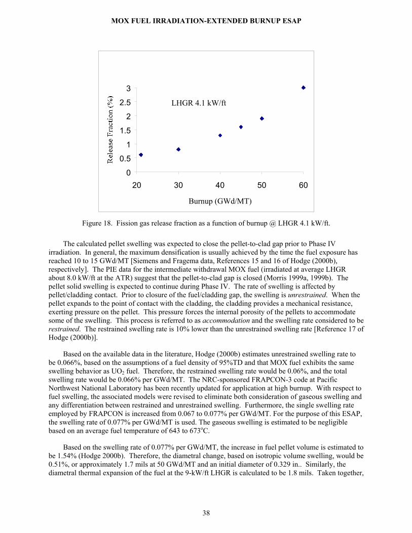
MOX FUEL IRRADIATION-EXTENDED BURNUP ESAP
38
LHGR 4.1 kW/ft
0
0.5
1
1.5
2
2.5
3
20 30 40 50 60
Burnup (GWd/MT)
Figure 18. Fission gas release fraction as a function of burnup @ LHGR 4.1 kW/ft.
The calculated pellet swelling was expected to close the pellet-to-clad gap prior to Phase IV irradiation. In general, the maximum densification is usually achieved by the time the fuel exposure has reached 10 to 15 GWd/MT [Siemens and Fragema data, References 15 and 16 of Hodge (2000b), respectively]. The PIE data for the intermediate withdrawal MOX fuel (irradiated at average LHGR about 8.0 kW/ft at the ATR) suggest that the pellet-to-clad gap is closed (Morris 1999a, 1999b). The pellet solid swelling is expected to continue during Phase IV. The rate of swelling is affected by pellet/cladding contact. Prior to closure of the fuel/cladding gap, the swelling is unrestrained. When the pellet expands to the point of contact with the cladding, the cladding provides a mechanical resistance, exerting pressure on the pellet. This pressure forces the internal porosity of the pellets to accommodate some of the swelling. This process is referred to as accommodation and the swelling rate considered to be restrained. The restrained swelling rate is 10% lower than the unrestrained swelling rate [Reference 17 of Hodge (2000b)].
Based on the available data in the literature, Hodge (2000b) estimates unrestrained swelling rate to be 0.066%, based on the assumptions of a fuel density of 95%TD and that MOX fuel exhibits the same swelling behavior as UO2 fuel. Therefore, the restrained swelling rate would be 0.06%, and the total swelling rate would be 0.066% per GWd/MT. The NRC-sponsored FRAPCON-3 code at Pacific Northwest National Laboratory has been recently updated for application at high burnup. With respect to fuel swelling, the associated models were revised to eliminate both consideration of gaseous swelling and any differentiation between restrained and unrestrained swelling. Furthermore, the single swelling rate employed by FRAPCON is increased from 0.067 to 0.077% per GWd/MT. For the purpose of this ESAP, the swelling rate of 0.077% per GWd/MT is used. The gaseous swelling is estimated to be negligible based on an average fuel temperature of 643 to 673oC.
Based on the swelling rate of 0.077% per GWd/MT, the increase in fuel pellet volume is estimated to be 1.54% (Hodge 2000b). Therefore, the diametral change, based on isotropic volume swelling, would be 0.51%, or approximately 1.7 mils at 50 GWd/MT and an initial diameter of 0.329 in.. Similarly, the diametral thermal expansion of the fuel at the 9-kW/ft LHGR is calculated to be 1.8 mils. Taken together,

MOX FUEL IRRADIATION-EXTENDED BURNUP ESAP
39
the fuel swelling and thermal expansion of the pellet represent a total diametral displacement of 3.5 mils. However, the thermal expansion of the Zr-4 cladding [Zr-4 average wall temperature 190oC (Ott 2000)] is calculated to be 0.4 mil. Therefore, to calculate the mechanical strain, total diametral displacement must be reduced by 0.4 mil. In other words, this outward pellet movement would force a diametral displacement of the Zr-4 cladding of approximately 3.1 (3.5 – 0.4) mils from the nominal fabricated dimension. Based on the expected dimensional changes, Hodge (2000b) predicted the decrease in the fuel pin gas volume to be equivalent to 5.25% of the initial fuel pin gas plenum free volume. In determining the pressure in the fuel pin, Hodge (2000b) conservatively used a 1.028 cm3 volume.
Based on a 3.1-mil diametral displacement, Hodge (2000b) estimates a Zircaloy-4 cladding hoop strain of approximately 0.87% for no pellet densification in scoping analyses, and the CARTS code predicted 0.99% for 0.5% pellet densification and 1.16% for no pellet densification. The calculated strains are not considered significant with respect to potential failure, due to the lack of hydriding and given that some creep relaxation will occur in the cladding (Hodge 2000b, Pedersen 2001).
An initial cladding-capsule diametral gap of 2 mils was conservatively used. At 9 kW/ft, the average capsule wall temperature is predicted to be about 116oC. The corresponding thermal expansion of the capsule is estimated to be approximately 0.6 mil, which in combination with the minimum initial cladding–capsule gap (2 mils) will partially accommodate the clad (fuel pin) diametral expansion. Therefore, the diametral displacement of the stainless steel capsule due to pellet and fuel pin expansion would equal 0.9 (3.5 minus 2.6) mil. This would induce a capsule wall strain of about 0.21%. Although yield occurs at about 0.2%, hoop strains approaching 20% can be accommodated in stainless steel without failure (Hodge 2000b). Luttrell (2000) shows a maximum strain of 0.38%, but also concludes that integrity/reliability of the capsules will be maintained.
The expected pressure (fission gas plus helium) in the fuel pin assembly at a burnup of 50 GWd/MT is calculated to be 474 and 207 psia for 11 and 4.5% release fraction, respectively (Hodge 2000b). Similarly, Hodge (2000b) estimated pressure within the combined fuel pin and SS capsule at the end of Phase IV irradiation (50 GWd/MT) to be 135.7 and 66 psia for 11 and 4.5% release fraction, respectively.
The fuel pin design pressure is 1425 psig, whereas the estimated failure pressure is from 3600 to 4155 psig. The simple calculations indicate that a fractional gas release of about 34% would be required to exceed design pressure and greater than 87% to exceed the lower boundary of the range of estimated failure pressure, i.e., 3600 psig. The literature indicates that, so far, the reported maximum release fraction is 31% at an LHGR of 15 kW/ft for the burnups between 30 to 50 GWd/MT (Hodge 1997b).
Therefore, fission gas releases from the MOX pellets do not threaten the integrity of a MOX capsule assembly, and its irradiation does not increase risk to the ATR operation.
Capsule Temperatures
The highest capsule temperatures occur at the fuel radial centerline. Using conservative estimates and assuming an LHGR of 9 kW/ft, the maximum fuel centerline temperature is estimated to be 1115°C during 2-pump operation. This temperature is more than 1500oC below the fuel melting temperature of 2653oC at 50 GWd/MT. Note that the programmatic maximum LHGR limit is 8 kW/ft.9 Therefore, these analyses are conservative. The melting temperature for UO2 plus 5 wt% PuO2 is 2813°C for fresh fuel and 2653°C for fuel at 50 GWd/MT burnup. The maximum fuel surface temperature is estimated to be less than 300°C. The maximum clad (zircalloy) temperature is calculated to be ~250°C, and the
9 Chang (2000) analyses indicate that maximum LHGR will not exceed 7 kW/ft.

MOX FUEL IRRADIATION-EXTENDED BURNUP ESAP
40
maximum capsule assembly (stainless steel) temperature is calculated to be ~150°C. The predicted fuel centerline, the MOX fuel capsule outer surface, and capsule assembly outer surface (i.e., stainless steel surface) temperatures for 30-, 40-, and 50-GWd/MT burnup are given in Figures 3.14, 3.21, and 3.28 of Ott (2000), respectively. The average gas temperature in the fuel pin upper plenum is calculated to be less than 160°C at a LHGR of 9 kW/ft and 11% release fraction (Hodge 2000b).
Coolant Pressure Drop and Temperature Rise Normal Operating Conditions Ott (2000) performed thermal hydraulic analyses for normal operation (two- and three-pump). The
test assembly will be in the I-23 position, located in the southwest (SW) quadrant of ATR and is operated at higher power levels. Chang (2000a) estimated the capsule LHGRs in the range of ~ 4 to 7 kW/ft during normal operations. However, for the purpose of this ESAP, Ott’s analyses assumed nine instead of five MOX capsule assemblies and a LHGR of 9 kW/ft for all capsule assemblies.
With three pumps in operation, a pressure drop of 87 psid across the ATR core and experimental test section was assumed. The overall fluid temperature rise was calculated to be 20 oF within the test assembly and 3.3 oF in the exterior coolant flow.
With two pumps in operation, a pressure drop of 67 psid across the ATR core and experimental test section was assumed. The overall fluid temperature rise was calculated to be 23 oF within the test assembly and 3.7 oF in the exterior coolant flow.
The results of the analyses discussed in this section are based on the Model-2 basket assembly and were verified by the INEEL experts (Ambrosek 2000).
Maximum Power in Southwest Lobe of 60-MW Operation Ott (2000) performed thermal hydraulic analyses for maximum lobe power (two- or three-pump).
The test assembly will be in the I-23 position, which is located in the southwest (SW) quadrant of ATR and is operated at higher power levels. Chang (2000a) estimates a maximum LHGR of less than 7 kW/ft for the test capsules with a SW lobe power of 23 MW. This ESAP is based on a LHGR of 9 kW/ft. Therefore, for the evaluation at 60 MW lobe power in the SW quadrant, a LHGR of 23.5 kW/ft (9*60/23) was used.
Three-pump operation: The minimum departure from nucleate boiling ratio (DNBR) was calculated to be in the capsule flow channels on the surfaces of the capsules at the ends of the fuel stacks. The minimum DNBR is 7.84. The minimum value of the flow stability criterion is 5.48 in the orifice.
Two-pump operation: The minimum DNBR was calculated to be in the capsule flow channels on the surfaces of the capsules at the ends of the fuel stacks. The minimum DNBR is 7.05. The minimum value of the flow stability criterion is 4.98 in the orifice.
The DNBRs and flow instability ratios are always greater than 2.0 for two- or three-pump operation, which meets the ATR safety requirements.
Experiment Reactivity As discussed in McCracken (1984), a reactivity worth of 1074 g U235 in a large I-hole was measured
to be less than 0.05$. The amount of fissile material (<12 g Pu) being introduced in the I-23 position for this irradiation, based on a maximum of 3 MOX fuel capsule assemblies, is equivalent to 25 g U-235. This prompts the conclusion that the reactivity insertion of the MOX experiment assembly is less than

MOX FUEL IRRADIATION-EXTENDED BURNUP ESAP
41
0.01$. This 0.01$ insertion is for a flat power scenario. In a conservative bounding case, 100 MW relative lobe power, reactivity insertion would be limited to 0.04$ (i.e., 0.01$*(100/50)2).
7.2.2 Condition 2 Anticipated Faults
The following Condition 2 faults are assessed.
Perched Test Assembly A perched test assembly that falls into place during reactor operation is an anticipated event. The
reactivity worth of the MOX test assembly is less than 0.01$, far below the 0.50$ reactivity limit for an anticipated fault. Therefore, a sudden drop in this assembly will not impact ATR operation.
Clad Failure For the purpose of this ESAP, failure of a fuel pin assembly zircaloy clad is considered to be an
anticipated fault. Each fuel pin assembly is encapsulated in a 304L stainless steel (SS) tube, as shown in Figure 1, that meets the ASME B&PV Code, Section III, Class 1, pressure vessel criteria (Luttrell 2000). The thermal hydraulic analysis, with two-pump operation and an LHGR of 9 kW/ft, shows that the capsule surface temperature is expected to be less than 100oC (Ott 2000). Fission gas leak analysis indicates that the capsule gas plenum essentially remains at local coolant temperature and shows very little variation, with almost no gas movement. No release of fission products outside of the stainless steel capsule is expected.
The fuel pin (clad) design pressure is 1425 psig, whereas the expected pressure (fission gas plus helium) in the fuel pin assembly at a burnup of 50 GWd/MT is calculated to be 474 and 207 psia for 11 and 4.5% release fraction, respectively (Hodge 2000b). The simple calculations indicate that a fractional gas release of about 34% would be required to exceed design pressure. The literature indicates that, so far, the reported maximum release fraction is 31% at an LHGR of 15 kW/ft for burnups between 30 to 50 GWd/MT (Hodge 1997b).
Similarly, Hodge (2000b) estimated pressure within the combined fuel pin and SS capsule at the end of Phase IV irradiation (50 GWd/MT) to be 135.7 and 66 psia for 11 and 4.5% release fraction, respectively, whereas the design pressure for the SS capsule is 1200 psia.
Flow Coastdown with Two Primary Pumps Initially Running As defined in Polkinghorne (1994), one potential abnormal condition is coastdown of the primary
coolant system (PCS) pumps (with an associated reactor scram with emergency flow) from a SW lobe power of 60 MW (from 250 MW ATR power) with two primary coolant pumps initially running. This accident is initiated by a loss of commercial power to the site. The minimum DNBR for this event occurs at the bottom of the last capsule in the capsule flow path. The minimum DNBR is 5.6. The minimum value of the flow stability criterion is 3.85 in the orifice. Both of these values are greater than 2.0, which meets the ATR safety requirements (Ott 2000). No release of fission products is expected in any anticipated event. Therefore, the consequences and risks are acceptable.
The MOX test assembly has been evaluated subjectively for natural convection cooling and for response to a reactivity-initiated transient, as related to the ATR TSR (TSR-186, 2001) and the ATR UFSAR (SAR-153, 2002) compliance.
The rationale for requiring a DNBR and FIR (flow instability ratio) greater than 2.0 is that an experiment is assured to have a greater margin of safety than the driver core. This leads to the

MOX FUEL IRRADIATION-EXTENDED BURNUP ESAP
42
requirement for assessment at the ATR UFSAR 10.3.5.2.1 (SAR-153, 2002) limits of lobe power for the irradiation position, since the driver core limits are based on lobe power limits. Provided there are no design features that will cause a degradation of natural convection, such as a check valve to restrict reverse flow, the experiment will have a safety margin not less than the driver core for natural convection cooling when the decay heat has a response equivalent or less severe than the driver fuel. The MOX assembly has no reverse flow device to hinder natural convection. Natural convection cooling in the MOX assembly is expected to be better than in an ATR fuel element, since a large portion of the operational pressure drop is across an orifice. The friction factor is usually higher for lower velocity flow, while form loss coefficients are essentially the same. The decay heating response in the MOX assembly is essentially the same as the driver fuel (and the heating rates in terms of watts per gram of fuel are always much less in the MOX capsules).
Natural convection cooling for the MOX assembly is bounded by the driver core response.
The argument for the ATR UFSAR 10.3.5.1.1 (SAR-153, 2002) compliance as above also holds for reactivity-initiated events.
The test requirements ensure that the experiment will maintain margins greater than the driver core. The evaluations for DNBR and FIR at the maximum lobe power and during a flow coastdown ensure that for experiments cooled by primary coolant the margins are not less than for the driver core.
7.2.3 Condition 3, Unlikely Faults Each fuel pin assembly is encapsulated in a 304L stainless steel (SS) tube, as shown in Figure 1, that
meets the ASME B&PV Code, Section III, Class 1, pressure vessel criteria (Luttrell 2000). Therefore, failure of a single capsule assembly is defined as an unlikely fault.
The fuel pin (clad) design pressure is 1425 psig, whereas the expected pressure (fission gas plus helium) in the fuel pin assembly at a burnup of 50 GWd/MT is calculated to be 474 and 207 psia for 11 and 4.5% release fraction, respectively (Hodge 2000b). The simple calculations indicate that a fractional gas release of about 34% would be required to exceed design pressure. The literature indicates that, so far, the reported maximum release fraction is 31% at an LHGR of 15 kW/ft for burnups between 30 to 50 GWd/MT (Hodge 1997b).
Similarly, Hodge (2000b) estimated pressure within the combined fuel pin and SS capsule at the end of Phase IV irradiation (50 GWd/MT) to be 135.7 and 66 psia for 11 and 4.5% release fraction, respectively, whereas the design pressure for the SS capsule is 1200 psia.
In case of an unlikely event, activity in the primary coolant is estimated based on the following assumptions:
• Instantaneous release of 100% of gaseous fission products from the plenum of the highest inventory capsule assembly (i.e., 11% of the total fission gas inventory) to the primary coolant
• Fission gases include Xe, Kr, I, and Cs
• Instantaneous homogeneous mixing in the PCS, i.e.; zero decay time
• Total PCS volume = 3.1E8 cc.
Using a nominal MOX fuel loading per capsule, Terry (1998a) performed an ORIGEN2 calculation of the radioactivity of actinides and fission products of all MOX capsules. Based on the maximum fission gas activity @ <10 GWd/MT burnup, the peak release from the failed capsule assembly results in less

MOX FUEL IRRADIATION-EXTENDED BURNUP ESAP
43
than 1.4 µCi/cc increase in the primary coolant activity, as shown in Figure 19. Normal primary coolant activity is 0.03 to 0.16 µCi/cc. The reactor primary coolant activity has a limit of 20 µCi/cc. Therefore, failure of a single capsule assembly will not approach the normal PCS activity operating limit. The fission products from plutonium are essentially the same as those from ATR fuel, so the potential stack release consequences from a MOX capsule are enveloped by those from ATR fuel for any unlikely event.
Figure 19. PCS activity: unlikely event.
This assessment is very conservative for the following reasons:
• The calculations show that the total fission gas inventory (Ci) decreases steadily, from 3386 Ci @ 8GWd/MT to 2634 Ci @30 GWd/MT, with burnup (Terry, 1998C, 1999, 2000)
• All capsules to be irradiated have accumulated about 30 GWd/MT burnup
• Zero decay time and instantaneous mixing is assumed.
7.2.4 Condition 4, Extremely Unlikely Faults Normally, the limiting credible fault associated with an irradiation program is an extremely unlikely
complete flow blockage to the I-hole position. The design of the MOX test assembly is such that it provides several holes strategically located on the test assembly (three 2-inch-long slots exist about 8 inches below the top of the test assembly). Flow blockage at the top of the test assembly may occur, but water would then flow into the slots to cool the MOX capsules. Therefore, water will always cool the capsules, because blockage of any flow path will not result in complete flow blockage.
Simultaneous failure of two or more MOX capsule assemblies is assumed to be an extremely unlikely fault. Failure of a single capsule assembly would result in less than 1.4 µCi/cc (@11% fission gas) in the primary coolant. Therefore, all five MOX capsule assemblies can experience simultaneous failures without exceeding the operating limit of 20 µCi/cc.
In the event of MOX fuel melting in the highest inventory (@ 8GWd/MT) capsule assembly, activity in the primary coolant is estimated based on the following assumptions:
MOX Experiment - 11% Fission Gas release
0.98
1.10
1.22
1.34
1.46
1 5 10 20 30 40 42
Irradiation time (d)

MOX FUEL IRRADIATION-EXTENDED BURNUP ESAP
44
• Instantaneous release of 100% of gaseous fission products plus 10% of the fission product particulates from the highest inventory capsule assembly to the primary coolant (Khericha 1998b)
• Fission gases include Xe, Kr, I, and Cs
• Simultaneous failure of capsule and fuel meltt
• Instantaneous homogeneous mixing in the PCS, i.e., zero decay time, total PCS volume = 3.1E8 cc.
No mechanism for this scenario has been identified. However, if the failure should occur, calculation shows that the maximum increase in the primary coolant activity would be 18 µCi/cc (see Figure 20), which is below the reactor primary coolant activity limit of 20 µCi/cc.
This assessment is very conservative, for the following reasons:
• The calculations show that the total fission product inventory (Ci) decreases steadily, from 1.98E4 Ci @ 8 GWd/MT to 1.28E4 Ci @ 30 GWd/MT, with burnup (Terry, 1998C, 1999, 2000),
• Aall the capsules to be irradiated have accumulated about~ 30 GWd/MT burnup,
• Zero decay time and instantaneous mixing are assumed
.Fission products generated by plutonium are essentially the same as those generated by the uranium in the ATR fuel. Any fission product release from the MOX capsules is enveloped by potential releases from ATR fuel. For example, the ATR limit on releasing fission product noble gases up the stack is 450 Ci/day. If we assume an instantaneous release of all the fission product noble gases from the gas plenum in one MOX capsule, directly up the stack, with no decay time or filtering in the primary coolant or degassing tank, a maximum of 115 Ci will go up the stack. This is well within the ATR limit for stack release.
The MOX capsules are nearly 10 times the density of water and will not float.
MOX Experiment - 100 % Fission gas release + 10 % Fission product particulates
14
15
16
17
18
1 5 10 20 30 40 42
Irradiation Time (d)
Mic
ro C
i/cc
of p
rimar
y co
olan
t
Figure 20. PCS activity: extremely unlikely event.

MOX FUEL IRRADIATION-EXTENDED BURNUP ESAP
45
7.3 Canal Activities Steps A, B, D, E, F, H, I, J, L, M, P, and N, Canal Activities
7.3.1 Condition 1, Normal Operations Any movement of the MOX test assembly within the ATR Canal area, or other operations involving
the irradiated MOX test assembly will be performed and controlled under a specific Radiological Work Permit.
Operations involving the MOX capsule assemblies in the ATR Canal (test assembly loading and unloading) are performed by personnel wearing dosimeters as specified in the RWP and are monitored by a Radiological Control Technician,. Personnel exposure rates are controlled by adjusting the depth of the canal working tray, where the capsules are located, as necessary to remain within the levels specified in the radiological work permit. Constant air monitors and remote area monitors are also in service as required by the Canal Operating and Maintenance Manual. ALARA principles are applied throughout the operation.
In relation to the MOX experiment being stored in the canal, three event categories (Condition 2, Condition 3, and Condition 4) were considered in the development of this ESAP.
7.3.2 Condition 2, Anticipated Faults
Dropping an Irradiated MOX Capsule to the Bottom of the Canal Accidental dropping of a MOX capsule during handling in the ATR Canal has been evaluated. A
maximum heating rate was used, as reported in Hodge (1997c), at approximately 8 GWd/MT and after 4 hr of cooling,. The maximum surface temperature is expected to be less than 100oF, and no boiling will occur on the capsule surface (Ambrosek 1997). This precludes any potential for dryout or temperature excursion. These MOX capsules are nearly 10 times denser than water and will not float. Restrictions will be placed in the Reactor Loading Record to prohibit transfer of the test assembly out of the reactor and to the canal in less than 4 hr after a reactor scram.
7.3.3 Condition 3, Unlikely Faults Minor Damage to a Single Capsule The MOX capsule assembly 304L SS outer pressure boundary meets ASME B&PV Code Section
III, Class 1. Minor damage to a single capsule is assumed to be a bounding unlikely event.
A release of 2% of the fission products from an ATR fuel plate is assumed to be an unlikely scenario. The total Pu inventories and 2% of the total fission products in an average fuel plate, 12 hr after reactor shutdown, are calculated to be 5.1 and 5816 Ci, respectively (Carboneau, 1993).
In the highest-inventory MOX capsule assembly, the total peak Pu inventories, and 100% of the total peak gaseous fission product inventory in the plenum (11% of total fission gas) plus 2% of solid fission

MOX FUEL IRRADIATION-EXTENDED BURNUP ESAP
46
products, 0 s after shutdown, are calculated to be ~2 and 544 Ci, respectively.10 The fission product source from the MOX capsules is much less than that of an ATR fuel plate, so the dose consequences from a MOX capsule are less than from a fuel plate. Therefore, the consequences from the MOX capsule assembly are enveloped in the case of an unlikely event of fission product gas release.
Use of the HCC 3, GE-100, or GE-2000 cask is governed by DOPs 4.8.19, 4.8.36, and 4.8.4, respectively, and Canal O&MM. The consequences of cask-drop unlikely events with any of these casks are within the cask-drop events analyzed in the UFSAR and will not increase as a result of this MOX fuel experiment.
Lifting an Irradiated Capsule Out of the Canal Water During manipulation of the capsule assemblies in the canal on the working tray area, an operator
lifting an irradiated assembly up out of the water is an unlikely event. A special canal tool is screwed into the top of each capsule to lift it out of the test assembly and onto the canal-working tray. The operator may not be aware that a capsule is attached to the end of the tool and could possibly lift it out of the canal water. During capsule manipulation, continuous RCT coverage is required. A Radiological Work Permit will control the job and establish acceptable dose rates. If the dose rate at the canal working level exceeds the predetermined limit, the work will be stopped and the canal working tray and capsule will be lowered in the canal. In case a capsule is pulled up too far, the canal area radiation alarms will go off, warning personnel. Movement of the test assembly in the canal is considered no different than movement of the ATR fuel element.
7.3.4 Condition 4, Extremely Unlikely Faults Simultaneous Minor Damage to Two Capsules or a Significant Fuel Meltdown of One Entire Capsule Complete meltdown of an ATR fuel element is assumed to be an extremely unlikely scenario. Total
fission products and total Pu inventories in an average fuel element, 8 hr after the shutdown, are calculated to be 6.3E6 and 1.37E2 Ci, respectively (SAR-153, 2002). In the highest-burnup MOX capsule assembly (assuming the complete meltdown of one capsule), total peak fission products and total Pu inventories, 4 hr after the shutdown, are calculated to be 5.5E3 and 2 Ci, respectively. The fission product and plutonium sources from the MOX capsule are much less than those of an ATR fuel element, so the dose consequences from a MOX capsule are less than from an ATR fuel element. Therefore, the consequences from the MOX capsule assembly are enveloped in the case of an extremely unlikely event.
Use of the HCC 3, GE-100, or GE-2000 cask is governed by the DOPs 4.8.19, 4.8.36, and 4.8.4, respectively, and Canal O&MM. The consequences of cask-drop extremely unlikely events with any of these casks are within the cask-drop events analyzed in the UFSAR and will not increase as a result of this MOX experiment.
7.4 Transport of Unirradiated or Irradiated Capsule Assemblies within TRA
Steps P and R, Transport of Unirradiated or Irradiated Capsule Assemblies within TRA
Transport of the HCC 3 cask between the TRA Hot Cell Facility and the ATR Canal is internally controlled by DOP 4.8.19. This DOP specifies the lift as a high consequence lift (stating the minimum
10 The calculations show that the total fission product inventory (Ci) decreases steadily from 1.98E4 Ci @ 8 GWd/MT to 1.28E4 Ci @ 30 GWd/MT with burnup (Terry 1998C, 1999, 2000). Total fission gas activity decreases from 3386 Ci @ 8GWd/MT to 2634 Ci @30 GWd/MT. Note that 4 hr after shutdown, the fission gas inventory has dropped more than 50%.
MOX FUEL IRRADIATION-EXTENDED BURNUP ESAP
47
capacity for the forklift), limits the speed on the roadway, and requires evaluation of road conditions in winter. These limitations ensure that probability is low for an upset that could cause damage to the cask and its contents.
Gentillo (1992) presents an engineering evaluation of the HCC 3 cask. Hawkes (1998, 1999a, 1999b) has analyzed the internal heatup of two capsule assemblies in HCC 3 or GE-100 cask. The internal heatup in the HCC 3 cask was found to be acceptable relative to heat generation limits noted in Sherick (1992). Similarly, the internal heatup in the GE-100 cask was also found to be acceptable. However, before each shipment, internal heatup rates will be verified to ensure that the shipment activity is bounded by the previous analyses, Hawkes (1998, 1999a, 1999b).
All capsule assemblies will be sealed in the isotope shipping canister during transfer in the HCC 3 cask per DOP 4.8.46. This sealed canister provides a barrier to prevent release if one of the capsules fails.
7.5 Cask Handling and Shipping Activity Steps O and Q, Loading Activity
The safety envelope for cask handling within the ATR is established by ATR TSR 3.5.5, Cask Handling and Irradiated Fuel Storage (TSR-186, 2001), and ATR UFSAR (SAR-153, 2002), and cask certificates of compliance. The loaded cask will be transported to ORNL per applicable DOE, DOT, and NRC requirements.
The GE-100 cask at the TRA HCF will be loaded in accordance with HCF procedures that reflect the facility’s operating requirements and cask certificate of compliance requirements. The loaded cask will be transported to ORNL per applicable DOE, DOT, and NRC requirements.

MOX FUEL IRRADIATION-EXTENDED BURNUP ESAP
48
8. PLANT PROTECTION CRITERIA This section discusses the four conditions for the Plant Protection Criteria for each of the process
steps.
8.1 Condition 1, Events Condition 1, Normal Operation: Condition 1 operations are expected to occur frequently or
regularly in the course of reactor operations, refueling, and maintenance.
Radiation Exposure Limits. Off-site: 100 mrem/year effective dose equivalent (EDE) and 10 mrem/year EDE from airborne release; Worker: 5 rem/year total effective dose equivalent (TEDE).
Barrier Protection Limits. The integrity of the ATR fuel cladding is not challenged in Condition 1, except for limited clad defects.
8.1.1 Irradiate the Test Assembly
Steps C and K: Irradiate the test assembly
Radiation Exposure. No Condition 1 events associated with irradiating the MOX capsules experiment have been identified that could cause off-site exposure. To limit worker exposure, radiological controls for all of the handling activities are performed in accordance with the Radiation Protection Manual.
Barrier Protection. No Condition 1 events associated with experiment irradiation have been identified that could possibly lead to ATR fuel cladding damage.
8.1.2 Canal Activities Steps D, H, and L: Transfer the test assembly to Canal.
Steps B, F, and J: Insert the test assembly into the Reactor.
Steps E: Replace the test assembly flux monitors.
Steps A, and M: Disassemble/assemble the test assembly on the working tray in the ATR Canal.
Radiation Exposure. No Condition 1 events associated with the canal activity steps listed above have been identified that could cause off-site exposure. To limit worker exposure, radiological controls for all of the handling activities are performed in accordance with the Radiation Protection Manual. Operations involving the MOX capsule assemblies and the MOX test assembly are monitored by a RCT, as specified in the RWP.
Barrier Protection. No Condition 1 events associated with disassembling and assembling the test assembly on the working tray in the ATR Canal have been identified that could possibly lead to damage to the fuel cladding.
8.1.3 Transport Unirradiated or Irradiated Capsule Assemblies and Basket Assembly
Steps P and R: Transport unirradiated or irradiated capsule assemblies in the ATR Canal/HCF.
Note that the following assessment of Plant Protection Criteria only applies to the specified process steps after the capsules enter the ATR facility. Once the shipping container leaves the ATR, the

MOX FUEL IRRADIATION-EXTENDED BURNUP ESAP
49
applicable Department of Transportation Code of Federal Regulations or DOP (for HCC 3) control the shipment, and this experiment is not under the control of the ATR UFSAR.
Radiation Exposure: No Condition 1 events associated with transferring unirradiated or irradiated MOX fuel, dummy capsule assemblies, or basket assemblies have been identified that could cause off-site exposure. To limit worker exposure, radiological controls for all handling activities are performed in accordance with the Radiation Protection Manual.
Barrier Protection. No Condition 1 events are associated with transferring unirradiated or irradiated MOX fuel, dummy capsule assemblies, and basket assemblies that have been identified that could possibly lead to damage to the ATR fuel cladding.
8.1.4 Store and Load the Irradiated Capsule Assemblies in the ATR Canal/HCF Steps I and N: Store the irradiated capsule assemblies in the ATR Canal.
Steps O and Q: Load the irradiated capsule assemblies, dummy assemblies, and basket assemblies, as needed, in the ATR Canal/HCF.
Radiation Exposure. No Condition 1 events associated with storage of the irradiated capsule assemblies and loading of the shipping cask have been identified that could cause off-site exposure. To limit worker exposure, radiological controls for all handling activities are performed in accordance with the Radiation Protection Manual.
Barrier Protection. No Condition 1 events associated with storage of the irradiated capsule assemblies and loading of the shipping cask have been identified that could possibly lead to damage to the ATR fuel cladding.
8.2 Condition 2, Anticipated Faults Condition 2, Anticipated Faults. Condition 2, anticipated fault, is an off-normal condition expected
to occur once or more during the lifetime of the facility due to an expected single fault.
Radiation Exposure Limits. Off-site: 0.5 rem/year TEDE; Worker: 5 rem/year TEDE.
Barrier Protection Limits. No rupture of the fuel plate cladding is allowable unless the clad failure is the initiating fault. For canal accidents, no melting of the fuel plate cladding is allowed.
8.2.1 Irradiate the Test Assembly
Steps C and K: Irradiate the test assembly.
Radiation Exposure. No Condition 2 faults associated with irradiating the MOX capsules experiment have been identified that could cause off-site exposure. To limit worker exposure, radiological controls for all handling activities are performed in accordance with the Radiation Protection Manual.
Barrier Protection. No Condition 2 faults associated with experiment irradiation have been identified that could possibly lead to ATR fuel cladding damage. The reactivity worth for the experiment was calculated to be less than 0.01$.
8.2.2 Canal Activities
Steps D, H and L: Transfer the test assembly to the canal.

MOX FUEL IRRADIATION-EXTENDED BURNUP ESAP
50
Steps B, F, and J: Insert the test assembly in the reactor.
Steps E: Replace the test assembly flux monitors.
Steps A, L, and M: Disassemble/assemble the test assembly on the working tray in the ATR Canal.
Radiation Exposure. No Condition 2 faults associated with the canal activities listed in the steps above have been identified that could cause off-site exposure. To limit worker exposure, radiological controls for all handling activities are performed in accordance with the Radiation Protection Manual. Operations involving the MOX capsule assemblies and the MOX test assembly are monitored by an RCT, as specified in the RWP.
Accidental dropping of a MOX capsule during handling in the ATR Canal has been evaluated. A maximum heating rate [as reported in (Hodge 1997c)], was used at approximately 8 GWd/MT and after 4 hr of cooling,. The maximum surface temperature is expected to be less than 100oF, and no boiling will occur on the capsule surface (Ambrosek 1997). This precludes any potential for dry out and temperature excursion. These MOX capsules are nearly ten times denser than water and will not float.
Barrier Protection: No Condition 2 faults associated with disassembling and assembling the test assembly on the working tray in the ATR Canal have been identified that could possibly lead to damage to the ATR fuel cladding. Dropping a MOX capsule assembly or the MOX test assembly as it is handled will not damage ATR fuel element cladding, because the fuel elements are stored in a different section of the canal located away from the working tray.
8.2.3 Transport of Unirradiated and Irradiated Capsule Assemblies and Basket Assembly
Steps P and R: Transport Unirradiated or Irradiated MOX fuel and dummy capsule assemblies and basket assembly.
Note that the following assessment of plant protection criteria applies only to the specified process steps after the capsules enter the TRA facility. Once the shipping container leaves TRA, the applicable Department of Transportation (DOT) Code of Federal Regulations (CFR), or DOP (for HCC 3) control the shipment, and this experiment is not under the control of the ATR UFSAR.
Radiation Exposure. No identified Condition 2 events are associated with transferring unirradiated or irradiated MOX fuel, dummy capsule assemblies, and basket assemblies that could cause off-site exposure. To limit worker exposure, radiological controls for all of the handling activities are performed in accordance with the Radiation Protection Manual.
Barrier Protection. No Condition 2 events are associated with transferring unirradiated or irradiated MOX fuel, dummy capsule assemblies, or basket assemblies that could cause damage to ATR fuel element cladding. Dropping any MOX capsule assembly as it is handled will not damage ATR fuel element cladding as the fuel elements are required to be properly stored upright in either the fuel annulus, fuel storage grids, or the fuel storage baskets in the vessel.
8.2.4 Store the irradiated capsule assemblies in the ATR Canal
Steps I and N: Store the irradiated capsule assemblies in the ATR Canal.
Steps O and Q, Loading activity: load the irradiated capsule assemblies, dummy assemblies, and basket assemblies, as needed, in the ATR Canal/HCF.

MOX FUEL IRRADIATION-EXTENDED BURNUP ESAP
51
Radiation Exposure. No Condition 2 faults associated with storage of the irradiated MOX capsule assemblies and the loading of the shipping cask have been identified that could cause off-site exposure. To limit worker exposure, radiological controls for all of the handling activities are performed in accordance with the Radiation Protection Manual.
Barrier Protection. No Condition 2 faults associated with storage of the irradiated MOX capsule assemblies and loading of the shipping cask have been identified that could possibly lead to damage to the ATR fuel cladding.
8.3 Condition 3, Unlikely Faults Condition 3, Unlikely Faults. These faults may occur infrequently during the life of the plant.
Radiation Exposure Limits: Off-site and evacuation worker: 6.25-rem whole body and 75-rem thyroid dose.
Barrier Protection Limits: The reactor primary coolant pressure boundary must be maintained unless its failure is the initiator. No large releases of uranium or fission products to the primary coolant system will occur.
8.3.1 Irradiate the Test Assembly
Steps C and K: Irradiate the test assembly.
Step I: Transfer the test assembly from I-24 to the I-23 position in the ATR.
Radiation Exposure. No Condition 3 faults associated with irradiating the MOX capsules experiment have been identified that could cause unacceptable off-site exposure. To limit worker exposure, radiological controls for all of the handling activities are performed in accordance with the Radiation Protection Manual. The stack release consequences for the MOX test assembly are enveloped by those from the ATR fuel for any unlikely events. Faw (1998) concluded, based on ORIGEN 2 and RSAC-5 calculations, that the MOX fuel would contribute less than 0.1% of the total dose at the LPZ (low population zone) if a postulated large break resulted in a release of radionuclides from both the ATR fuel and the MOX fuel.
Barrier Protection. No Condition 3 faults associated with experiment irradiation have been identified that could possibly lead to ATR primary coolant pressure boundary damage. No Condition 3 faults associated with MOX capsule irradiation have been identified that could possibly lead to large releases of uranium or fission products to the primary coolant. See Section 7.2.3 for discussion of failure of a single capsule assembly.
8.3.2 Canal Activities
Steps D, H, and L: Transfer the test assembly to the canal.
Steps B, F, and J: Insert the test assembly in the Reactor.
Steps E: Replace the test assembly flux monitors.
Steps A and M: Disassemble/assemble the test assembly on the working tray in the ATR Canal.
Radiation Exposure. No Condition 3 events associated with disassembling and assembling the MOX test assembly on the working tray in the ATR Canal have been identified that could cause unacceptable off-site exposure. To limit worker exposure, radiological controls for all handling activities are

MOX FUEL IRRADIATION-EXTENDED BURNUP ESAP
52
performed in accordance with the Radiation Protection Manual. Operations involving the MOX capsule assemblies and the MOX test assembly are monitored by a RCT, as specified in the RWP.
The total amount of Pu and fission products releasable from the MOX test assembly experiment is bounded by the ATR fuel for any unlikely event. See Section 7 for an assessment of a fault involving lifting an irradiated capsule out of the canal.
Barrier Protection. No Condition 3 events associated with disassembling and assembling the MOX test assembly on the working tray in the ATR Canal have been identified that could possibly lead to damage to the ATR primary coolant pressure boundary.
8.3.3 Transport of Unirradiated and Irradiated Capsule Assemblies and Basket Assembly
Steps P and R: Transport unirradiated and irradiated MOX fuel and dummy capsule assemblies and basket assembly.
Note that the following assessment of plant protection criteria only applies to the specified process steps after the capsules enter the TRA facility. Once the shipping container leaves TRA, the applicable Department of Transportation Code of Federal Regulations, or DOP (for HCC 3), control the shipment, and this experiment is not under the control of the ATR UFSAR.
Radiation Exposure. No Condition 3 faults associated with transferring unirradiated or irradiated MOX fuel, dummy capsule assemblies, and basket assemblies have been identified that could cause unacceptable off-site exposure. To limit worker exposure, radiological controls for all handling activities are performed in accordance with the Radiation Protection Manual.
Barrier Protection. No Condition 3 faults associated with transferring unirradiated or irradiated MOX fuel, dummy capsule assemblies, or basket assemblies have been identified that could possibly lead to damage to the ATR primary coolant pressure boundary.
8.3.4 Store the Irradiated Capsule Assemblies in the ATR Canal
Steps I and N: Store the irradiated capsule assemblies in the ATR Canal.
Steps O and Q, Loading activity: Load the irradiated capsule assemblies, dummy assemblies, and basket assemblies, as needed, in the ATR Canal/HCF
The following cask handling and fuel element damage faults have been classified as Condition 3 faults (SAR-153, 2002):
• Dropping a heavy cask from an elevation of less than one foot above the canal floor or other small or limited failure of the storage canal
• Dropping a heavy cask from one foot above a parapet within the restricted cask-lifting areas of the canal
• Dropping a heavy cask onto the floor north of the canal
• Minor damage to one fuel element in the canal, with a minor fission product release.
As shown in the ATR UFSAR, Chapter 15, these faults will meet the ATR plant protection criteria for primary coolant pressure boundary protection and radiation exposure if the cask handling requirements in the ATR TSR and UFSAR are followed. Compliance with the ATR TSR and UFSAR for this experiment is demonstrated in Section 6 of this ESAP.
MOX FUEL IRRADIATION-EXTENDED BURNUP ESAP
53
Radiation Exposure. No Condition 3 faults associated with storage of the irradiated capsule assemblies and the loading of the shipping cask have been identified that could cause unacceptable off-site exposure. To limit worker exposure, radiological controls for all handling activities are performed in accordance with the Radiation Protection Manual. Faw (1998) concluded, based on ORIGEN 2 and RSAC-5 calculations, that the MOX fuel would contribute less than 0.1% of the total dose at the LPZ (low population zone) if a postulated large break resulted in release of radionuclides from both the ATR fuel and the MOX fuel.
During manipulation of the capsule assemblies in the canal on the working tray area, an operator lifting an irradiated assembly out of the water is an unlikely event. A special canal tool is screwed into the top of each capsule to lift it out of the test assembly and onto the canal working tray. The operator may not be aware that a capsule is attached to the end of the tool and could possibly lift it out of the canal water. During capsule manipulation, a person from radiological control will be present and monitor any work in the canal. If the dose rate at the canal working level exceeds the predetermined limit, the work will be stopped, and the canal working tray and capsule will be lowered in the canal. It is expected that the canal area radiation alarms will also go off, warning personnel in case a capsule is pulled up too far. Movement of the test assembly in the canal is considered no different than movement of the ATR fuel element, and consequences are bounded by the lifting of an ATR fuel element out of the water.
Minor damage to a single MOX capsule has been established as a bounding Condition 3 fault (which is enveloped by the UFSAR fault for fuel element damage, noted above). See the MOX capsule damage assessment in Section 7.3.2.
Barrier Protection. No Condition 3 events associated with storage of the irradiated capsule assemblies and the loading of the shipping cask have been identified that could possibly lead to damage to the ATR primary coolant pressure boundary.
8.4 Condition 4, Extremely Unlikely Faults Condition 4, Extremely Unlikely Faults, are low-probability faults that are not expected to occur but
are postulated because their consequences include the potential for release of significant quantities of radioactive material.
Radiation Exposure Limits. Off-site and evacuation worker: 25-rem whole body and 300-rem thyroid dose.
Barrier Protection Limits. The primary coolant pressure boundary must be maintained unless its failure is the initiator, and reactor confinement must not be damaged.
8.4.1 Irradiate the test assembly: Steps C and K Radiation Exposure. No Condition 4 faults associated with irradiating the MOX capsules experiment
have been identified that could cause unacceptable off-site exposure. To limit worker exposure, radiological controls for all of the handling activities are performed in accordance with the Radiation Protection Manual. The release consequences from the experiment are enveloped by those from ATR fuel for any extremely unlikely events. See Section 7 (Simultaneous Failure of Two MOX Capsules). Faw (1998) concluded, based on ORIGEN 2 and RSAC-5 calculations, that the MOX fuel would contribute less than 0.1% of the total dose at the LPZ (low population zone) if a postulated large break resulted in release of radionuclides from both the ATR fuel and the MOX fuel.
Barrier Protection. No Condition 4 faults associated with MOX test assembly irradiation have been identified that could possibly lead to ATR primary coolant pressure boundary or confinement damage.

MOX FUEL IRRADIATION-EXTENDED BURNUP ESAP
54
8.4.2 Canal Activities
Steps D, H, and L: transfer the test assembly to the canal.
Steps B, F, and J: insert the test assembly in the Reactor.
Steps E: replace the test assembly flux monitors.
Steps A and M: disassemble/assemble the test assembly on the working tray in the ATR Canal.
Radiation Exposure. No Condition 4 events associated with disassembling and assembling the test assembly on the working tray in the ATR Canal have been identified that could cause off-site exposure. To limit worker exposure, radiological controls for all of the handling activities are performed in accordance with the Radiation Protection Manual. Operations involving the MOX capsule assemblies and the MOX test assembly are monitored by an RCT, as specified in the RWP.
Condition 4 events of simultaneous minor damage to two capsules or a significant fuel meltdown of one entire capsule are discussed in Section 7.
The total amount of Pu and fission products releasable from the MOX experiment is bounded by the ATR fuel for any extremely unlikely event.
Barrier Protection. No Condition 4 faults associated with disassembling and assembling the MOX test assembly on the working tray in the ATR Canal have been identified that could possibly lead to damage to the ATR primary coolant pressure boundary or confinement damage.
8.4.3 Transport of Unirradiated and Irradiated Capsule Assemblies and Basket Assembly
Steps P and R: Transport unirradiated or irradiated MOX fuel and dummy capsule assemblies and basket assembly.
Note that the following assessment of plant protection criteria applies only to the specified process steps after the capsules enter the ATR facility. Once the shipping container leaves the ATR, the applicable DOT regulations, or DPO (for HCC 3), control the shipment, and this experiment is not under the control of the ATR UFSAR.
Radiation Exposure. No Condition 4 faults associated with transferring unirradiated or irradiated MOX fuel, dummy capsule assemblies, and basket assemblies have been identified that could cause unacceptable off-site exposure. To limit worker exposure, radiological controls for all of the handling activities are performed in accordance with the Radiation Protection Manual.
Barrier Protection. No Condition 4 faults associated with transferring unirradiated or irradiated MOX fuel, dummy capsule assemblies, and basket assemblies have been identified that could possibly lead to damage to the ATR primary coolant pressure boundary or confinement damage.
8.4.4 Store the Irradiated Capsule Assemblies in the ATR Canal
Steps I and N: Store the irradiated capsule assemblies in the ATR Canal.
Steps O and Q, Loading activity: load the irradiated capsule assemblies, dummy assemblies, and basket assemblies, as needed, in the ATR Canal/HCF.
Radiation Exposure. No Condition 4 events associated with storage of the irradiated MOX capsule assemblies and the loading of the shipping cask have been identified that could cause unacceptable off-

MOX FUEL IRRADIATION-EXTENDED BURNUP ESAP
55
site exposure. To limit worker exposure, radiological controls for all of the handling activities are performed in accordance with the Radiation Protection Manual. The total amount of Pu and fission products releasable from the MOX experiment is bounded by the ATR fuel for any extremely unlikely event. The extremely unlikely events of simultaneous minor damage to two capsules or a significant fuel meltdown of one entire capsule are discussed in Section 7.
Barrier Protection. No Condition 4 faults associated with storage of the irradiated MOX capsule assemblies and the loading of the shipping cask have been identified that could possibly lead to damage to the ATR primary coolant pressure boundary or confinement damage.
MOX FUEL IRRADIATION-EXTENDED BURNUP ESAP
56
9. UNREVIEWED SAFETY QUESTIONS Based on Sections 7 through 8 of this ESAP, Unreviewed Safety Question (USQ) Screen SES-2002-
120 (attached), and USQ Evaluation SE-2002-049 (attached), the installation, irradiation, and operation of the MOX experiment in the ATR does not constitute an Unreviewed Safety Question (USQ).

MOX FUEL IRRADIATION-EXTENDED BURNUP ESAP
57
10. CONCLUSIONS Operation with the MOX capsule experiment is within the safety envelope of the ATR TSR and the
UFSAR, and the experiment can proceed as planned.

MOX FUEL IRRADIATION-EXTENDED BURNUP ESAP
58
11. REFERENCES Ambrosek, R. G., 1997, Letter to S. T. Khericha, “Maximum Surface Temperature for MOX Capsule
Horizontal on Canal Floor,” AMB-13-97, December 3, 1997.
Ambrosek, R. G., 1998, Letter to S. T. Khericha, “Review of LWR MOX Test Assembly Flow Test Report,” AMB-02-98, January 19, 1998.
Ambrosek, R. G., 2000, Letter to S. T. Khericha, “Thermal/Hydraulic Review for Phase IV MOX Irradiation,” AMB-05-00, September 13, 2000.
Bayless, P. D., 1998, Letter to J. M. Ryskamp, “Air Cooling Analysis of MOX Test Assembly,” PDB1-98, March 17, 1998.
Boston, R. D., 1998, Letter to J. M. Ryskamp, “Criticality Safety of MOX Fuel Pins in Advance Test Reactor Basket Assembly,” RDB-16-98, June 3, 1998
Carboneau, M. L., ORIGEN2 Calculated Core Inventories and Photon Source Term for the ATR SAR, EDF TRA-ATR-784, INEEL, Idaho Falls, ID, May 1993
Chang, G. S., 2000a, Letter to R. C. Pedersen, “MCNP-Calculated MOX Fuel Capsule Burnup and LHGR During Phase–IV, Part 1A, 1B, 2, and 3 Irradiation,” ORMOX-GSC-08-00, March 17, 2000.
Chang, G. S., 2000b, Letter to R. C. Pedersen, “MCNP-Calculated MOX Fuel Capsule Burnup and LHGR During Phase–III, Part 2 Irradiation During Cycles 123b, 123C, and 124A,” ORMOX-GSC-22-00, August 7, 2000.
Chang, G. S., 2000c, Letter to R. C. Pedersen, “Prediction of Linear Heat generation Rates (LHGR) in MOX Fuel Test Capsule at the Beginning of Cycle 121C,” ORMOX-GSC-05-00, February 15, 2000.
Chang, G. S., 2001, Letter to R. C. Pedersen, “Best Estimate of MOX Fuel Capsule burnup and LHGR During Phase IV Irradiation to 50 GWD/MT,” ORMOX-GSC-13-01, September 27, 2001.
Chidester, K. M. , 1998, Letter to J. M. Ryskamp, NMT-9/98-012, January 13, 1998.
Cooper C. D., 1997, Letter to J. M. Ryskamp, “Review of the Oak Ridge and Los Alamos Quality Program Documents, CDC-06-97, October 1997.
Cooper C. D., 1998, Letter to J. M. Ryskamp, “Quality Certification for the Mixed Oxide (MOX) Fuel Test Assembly,” CDC-01-98, January 1998.
Corum, J. E., 1997, Design Calculations in Support of the Advanced Test Reactor Mixed Oxide (ATR-MOX) Fuel Irradiation Experiment, ORNL/MD/LTR/-92, July 1997.
Corum, J. E., 1998, and K. H. Luk, Addendum-1 to the Design Calculations in Support of the Advanced Test Reactor Mixed Oxide (ATR-MOX) Fuel Irradiation Experiment, X-OE-714 ADDENDUM-1 ORNL/MD/LTR-92, January 1998.
Cowell, B. S., 1996, Light Water Reactor (LWR) Mixed Oxide Fuel Kickoff Meeting October 8-9, 1996, Oak Ridge, Tennessee, ORNL/MD/LTR-59, November 1996.
Cowell, B. S., 1997a, Purchase Order: Mixed-Oxide Capsule Assemblies, ORNL/MD/LTR-90, August 1997.
Cowell, B. S., 1997b, ATR Capsule Assembly Loading and Operation Schedule, ORNL/MD/LTR-91, September 1997.
Cowell, B. S., 1998a, and S. A. Hodge, Fissile Materials Disposition Program Light

MOX FUEL IRRADIATION-EXTENDED BURNUP ESAP
59
Water Reactor Mixed Oxide Fuel Irradiation Test Project Plan, Rev. 1, February 1998.
Cowell, B. S., 1998b, ATR Capsule Assembly Loading and Operation Schedule, ORNL/MD/LTR-91, Rev. 1, February 1998.
Cowell, B. S., 2000a, and S. A. Hodge, ATR Capsule Assembly Loading and Operation Schedule, ORNL/MD/LTR-91, Rev. 2, February 2000.
Cowell, B. S., 2000b, and S. A. Hodge, Fissile Materials Disposition Program Light
Water Reactor Mixed Oxide Fuel Irradiation Test Project Plan, ORNL/MD/LTR-78, May 2000.
Cowell, B. S., 2000c, and S. A. Hodge, ATR Capsule Assembly Loading and Operation Schedule, ORNL/MD/LTR-91, Rev. 3, August 2000.
Cowell, B. S., 2001, and S. A. Hodge, ATR Capsule Assembly Loading and Operation Schedule, ORNL/MD/LTR-91, Rev. 4, October 2001.
DOE (1992), “Nuclear Safety Analysis Reports,” DOE Order 5480.23, April 1992.
Faw, E., (1998) Letter to J. M. Ryskamp, “MOX Contribution to Radiation for a Postulated Nuclear Incident at ATR,” EMF-01-98, August 1998.
Gentillo, T. A., 1992, W.E. #3 Independent Engineering Evalution, EDF TRA-ATR-660, Rev. 1, November 1992.
Grover, S. B., 1998a, Final Design Review for the MOX Test Aluminum Filler Assembly /Installation, SBG-10-98, September 23, 1998.
Grover, S. B., 1998b, Final Design Review Closure to the ATR-MOX Capsule Carrier and Capsule Long Insertion Tool, SBG-08-98, September 14, 1998.
Grover, S. B., 2000a, Report of ATR MOX Irradiation Phase IV Extended Burnup Design Review Meeting, CCN 00-010861, July 6, 2000.
Grover, S. B. (2000b), Final Design Review Closure of ATR-MOX Irradiation Phase IV Extended Burnup, CCN 00-012816, August 31, 2000.
Hawkes, G. L. (1998) Letter to S. Khericha, “Letter Report on MOX Fuel Thermal Analysis,” GLH-03-98, October 1, 1998.
Hawkes, G. L., 1999a, R. G. Ambrosek, W. K. Terry, Thermal Analyses of MOX Fuel Capsule Assembly, INEEL/EXT-99-00489, May 1999.
Hawkes, G. L., 1999b, Letter to R. A. Roesener, “Letter Report on MOX Fuel Thermal Analysis for Transport in GE-100 Cask,” GLH-03-99, October 4, 1999.
Heatherly, D. W., and K. R. Thoms 1998, Drawings X2E801214A001 through X2E801214A035, Oak Ridge National Laboratory, December 4, 1998
Hodge, S. A., 1997a, Letter to J. M. Ryskamp, "Removal of Irradiated MOX Capsules
and Related Hardware from the INEEL to ORNL,” November 1997.
Hodge, S. A., 1997b, Effects of Fission Gas Release and Pellet Swelling Within the LWR Mixed Oxide Irradiation Test Assembly, ORNL/MD/LTR-83, Rev. 1, November 1997.
Hodge, S. A., 1997c, Facsimile to J. M. Ryskamp, “Decay Heat and Activity Values for the ATR Capsule,” (Brian D. Murphy, ORNL), July 24, 1997.
Hodge, S. A., 1998, Facsimile to R. C. Pedersen, et al., “Model 2 Basket Nonconformance Report,” ORNL, October 1, 1998.

MOX FUEL IRRADIATION-EXTENDED BURNUP ESAP
60
Hodge, S. A., 2000a, Overview of Safety Analyses for MOX Irradiation Phase IV Extended Burnup, ORNL/MD/LTR-194, June 2000.
Hodge, S. A., 2000b, Fission Gas Release and Pellet Swelling Within the Capsule Assembly During Phase IV of the Average Power Test, ORNL/MD/LTR-184, Level 2, July 2000.
Hodge, S. A., 2002a, E-mail to R. C. Pedersen, et al., “Minutes – April 25 Telecon – Task 2.2,” ORNL, April 25, 2002.
Hodge, S. A., 2002b, L. J. Ott, F. P. Griffin, and C. R. Luttrell, Implication of the PIE Results for the 30-GWd/MT-Withdrawal MOX Capsules, Volume 2, Rev. 2, ORNL/MDL/LTR-212, February 2002
Khericha, S. T., 1998a, R. C. Pedersen, B. L. Barnes, Auditable Safety Analysis for Mixed Oxide (MOX) Fuel Capsules in the TRA-635 Radiography Facility, INEEL/INT-97-01279, January 1998.
Khericha, S .T., 1998b, J. M. Ryskamp, Experiment Safety Assurance Package (ESAP) for Mixed Oxide Fuel Irradiation in an Average Power Position (I-24) in the Advanced Test Reactor, INEEL/EXT-98-00291, March 1998.
Khericha, S .T., 2000, R. C. Howard, Experiment Safety Assurance Package for Mixed Oxide Fuel Irradiation in an Average Power Position (I-24) in the Advanced Test Reactor, INEEL/EXT-2000-01043, May 2000.
Khericha, S. T., R. C. Howard 2001, Experiment Safety Assurance Package (ESAP) for Extended Burnup Phase of Mixed Oxide Fuel Irradiation in Small I-hole Positions in the Advanced Test Reactor, INEEL/EXT-01-00190, February 2001.
Luttrell, C. R., and G. T. Yahr 2000, Design-Calculations for Phase IV of the Advanced Test Reactor Average –Power Mixed Oxide Fuel Irradiation Experiment, Rev. 0, ORNL/MD/LTR-192, August 2000.
McCracken, R. T., 1984, ATRC Data From the Large I-Hole Fueled Experiment, INEEL, RE-PB-84-021, March 29, 1984.
Miller G., 2000, Letter to S. T. Khericha, “Review of Design Calculation for ATR MOX Irradiation Phase IV Extended Burnup,” GKM-02-00, September 12, 2000.
Morton, D. K., 1997, Letter to S. T. “Khericha, Structural Review of ATR MOX Fuel Irradiation Experiment,” DKM-11-97, December 18, 1997.
Morris, R. N., et al. 1999a, MOX Average Power Early PIE: 8 GWd/MT Quick Look, ORNL/MD/LTR-163, Rev. 1, February 1999.
Morris, R. N., 1999b, et al., MOX Average Power Early PIE: 8 GWd/MT Final Report, ORNL/MD/LTR-171, Rev. 0, November 1999.
Morris, R. N., J. Giaquinto, S. A. Hodge 2000a, MOX Average Power Test Fuel Pellet Initial Gallium Content, ORNL/MD/LTR-182, March 2000.
Morris, R. N., C. A. Baldwin, et al. 2000b, MOX Average Power Intermediate PIE: 21 GWd/MT Quick Look, ORNL/MD/LTR-185, March 2000.
Morris, R. N., C. A. Baldwin, et al. 2001, MOX Average Power Test 30 GWd/MT PIE: Final Report, ORNL/MD/LTR-212, November 2001.
NCR, 1998, Nonconformance Report on Model 2 Aluminum Basket Assembly, NCR TRA-OP-M2612 October 1,1998.
NFAC-OSB, 1996, Interim Operational Safety Basis Report for Test Reactor Area Nonfacility Nuclear Operations, NFAC-OSB.R00, Rev. 0, January 25, 1996.

MOX FUEL IRRADIATION-EXTENDED BURNUP ESAP
61
Ott, L. J., 1998a, Flow Test of the MOX Test Basket Assembly, ORNL/MD/LTR-118, January 1998.
Ott, L. J., 1998b, Flow Test of the Model-2 MOX Test Basket Assembly, ORNL/MD/LTR-149, August 1998.
Ott, L. J., 2000, Thermal/Hydraulic Calculations for Phase IV of the LWR MOX Irradiation Average-Power Test, ORNL/MD/LTR-191, July 2000.
Pedersen, R.C., 1998a, “MOX Capsule Loading Information,” RCP-09-98, September 16, 1998.
Pedersen, R.C., 1998b, “Hazard Classification for the Transport of Irradiated MOX Capsule in the Hot Cell Carrier 3 (HCC #3),” RCP-10-98, October 26, 1998.
Pedersen, R.C., 2001, “Clarification of MOX Fuuel Pin Clad Strain Limit,” RCP-02-01, January 15, 2001.
Polkinghorne, S. T., 1994, ATR-SINDA and SINDA–SAMPLE Calculation for Chapter
15 of the ATR Updated UFSAR, EDF TRA-ATR-840, February 1994.
Roesener, R. A., 1998a, Confirmatory Analysis – Two Irradiated Phase I MOX Capsule Assemblies Transport to ORNL in General Electric Model 100 Transport Package, EDF INEEL/INT-98-001147, November 10, 1998.
Roesener, R. A., 1998b, Confirmatory Analysis – Two Unirradiated Archive MOX Capsule Assemblies Transport in 10-Gallon 6M/2R to ORNL, EDF INEEL/INT-98-002000, February 26, 1998.
Roesener, R. A., 1999, Confirmatory Analysis – Transport of Average Power Test Phase I I Irradiated MOX Fuel Capsule Assemblies in General Electric Model 100 Packaging, EDF INEEL/INT-99-01009, October 5, 1999.
Roesener, R. A., 2000, Confirmatory Analysis – Transport of Average Power Test Phase III/Part 1 Irradiated MOX Fuel Capsule Assemblies in General Electric Model 100 Packaging, EDF INEEL/EXT-2000-01082, September 6, 2000.
Roesener, R. A., 2002, Confirmatory Analysis – Transport of Average Power Test Phase IV/Part 1 Irradiated MOX Fuel Capsule Assemblies in General Electric Model 100 Packaging, EDF-2111, Rev. 1, Idaho National Engineering and Environmental Laboratory, April 24, 2002.
Ryskamp, J. M., 1997, Facsimile to S. A. Hodge, “Address MOX Capsules Criticality Concerns,” September 22, 1997.
Ryskamp, J. M., S. A. Hodge, and B. S. Cowell 1998, “A Mixed Oxide Fuel Irradiation Experiment in the Advanced Test Reactor,” Proceedings of the Sixth International Conference on Nuclear Engineering, CD-ROM Fall Paper, Book of Abstracts, Page 653, San Diego, CA, May 10-15, 1998.
SAR-153, 2002, Safety Analysis Report for the Advanced Test Reactor, Rev. 8, January 2002.
Shappert, L. B., L. S. Dickerson, and S. B. Ludwig, Irradiated Test Fuel Shipment Plan for the LWR MOX Fuel Irradiation Test Project, ORNL/MD/LTR-101, Level 2, October 1998.
Sherick, M. J., 1992, Letter to D. L. Batt, “White Elephant (WE) Cask #3 Safety Evaluation,” MJS-7-92, April 24, 1992.
Terry, W. K., 1998a, Letter to J. M. Ryskamp, “MOCUP Calculations of Radionuclide Content in MOX Fuel Capsules to be Irradiated in the Advanced Test Reactor,” WKT-02-98, January 28, 1998.
Terry, W. K., 1998b, Letter to J. M. Ryskamp, “Clarification of Table Headings,” WKT-14-98, October 1, 1998.

MOX FUEL IRRADIATION-EXTENDED BURNUP ESAP
62
Terry, W. K., 1998c, Letter to R. C. Pedersen, “As-Run Radiological Characterization of MOX Fuel Capsules Removed from the ATR After Cycle 117B,” WKT-15-98, October 15, 1998.
Terry, W. K., 1999, Letter to R. C. Pedersen, “As-Run Radiological Characterization of MOX Fuel Capsules Removed from the ATR After Cycle 120A,” WKT-04-99, November 8, 1999.
Terry, W. K., 2000, Letter to R. C. Pedersen, “As-Run Radiological Characterization of MOX Fuel Capsules Removed from the ATR After Cycle 122C,” WKT-02-00, August 15, 2000.
Thoms, K. R. (1997a), Design, Functional, and Operational Requirements for the Advanced Test Reactor Mixed Oxide Fuel Irradiation Experiment, ORNL/MD/LTR-76, Rev. 1, September 1997.
Thoms, K. R. , 1997b, Facsimile to J. M. Ryskamp, “Minimum Wall for Weld Defects,” December 1997.
Thoms, K. R., 2000, Design, Functional, and Operational Requirements for Phase IV of the Average-Power Mixed-oxide Irradiation Test, ORNL/MD/LTR-187, March 2000.
Tomberlin, T. A. (1997), “MOX Capsule Experiment Relative to ATR Authorization Basis,” Tom-06-97, November 13, 1997.
TSR-186, 2001, Technical Safety Requirements for the Advanced Test Reactor, Rev. 6, INEEL, December 2001.
Wachs, G. W. (1997), Fabrication, Inspection, and Test Plan for the Advanced Test Reactor (ATR) Mixed-Oxide (MOX) Fuel Irradiation Project, INEEL/EXT-97-01066, November 1997.
West, P. B., (1997a), Letter to Distribution, “Report of Design Review,” PBW-02-97, August 20, 1997.
West, P. B., (1997b), Letter to Distribution, “MOX Test Design Verification Closure,” PBW-03-97, November 5, 1997.
Wilson, D. F., et al (1997), Interactions of Zircaloy Cladding with Gallium 1997 Status, ORNL/TM-13505, November 1997.


