experimental analysis of jet ejector by … mech - ijmperd... · 99 experimental analysis of jet...
TRANSCRIPT
EXPERIMENTAL ANALYSIS OF JET EJECTOR BY FORCED DRAUGHT 1S. GURULINGAM, 2A. KALAISSELVANE & 3N. ALAGUMURTHY
1Research scholar, Department of Mechanical Engineering, Pondicherry Engineering College 2Assistant Professor, Department of Mechanical Engineering, Pondicherry Engineering College
3Professor, Department of Mechanical Engineering, Pondicherry Engineering College
ABSTRACT
A jet compressor uses a jet of primary fluid to induce a peripheral secondary flow often against back
pressure. Expansion of primary jet produces a partial vacuum near the secondary flow inlet creating a rapid re-
pressurization of the mixed fluids followed by a diffuser to increase the pressure at the exit. Using the
geometrical design parameters obtained by solving the governing equations, a CFD analysis is made using the
FLUENT software to evaluate the optimum entrainment ratio that could be achieved for a given set of operating
conditions, where the entrainment ratio (ER) is the ratio of the mass flow rate of the secondary fluid (propelled
stream) to the primary fluid (motive fluid). In this paper a jet compressor’s performance analysis is made using
irreversibility characteristics .the various losses that occurs in different regions of jet compressor are quantified.
Effort is made to increase the efficiency of jet compressor by reducing the losses based on minimization of
entropy method. In order to match the ER that is achievable theoretically, an effort is made to force (charge) the
propelled stream using a blower. So that the momentum difference between the motive and the propelled fluid
is minimized. Experimental results obtained using the forced draft system is found to match the results obtained
from the FLUENT analysis.
KEYWORDS: Ejector, Efficiency, Forced Draught
INTRODUCTION
Jet ejectors are the simplest devices among all compressors and vacuum pumps. They do not
contain any moving parts, lubricants or seals; therefore, they are considered as highly reliable devices
with low capital and maintenance costs. Furthermore, most jet ejectors use steam or compressed air as
the motive fluid, which is easily found in chemical plants. Due to their simplicity and high reliability,
they are widely used in chemical industrial processes; however, jet ejectors have a low efficiency. [1]
Journal of Mechanical and Production Engineering (JMPE) ISSN 2278-3512 Vol.2, Issue 2, Sep 2012 98-108 © TJPRC Pvt. Ltd.,

99 Experimental Analysis of Jet Ejector by Forced Draught
Fig. 1 Cross sectional view of a typical liquid jet pump
A high-pressure fluid with very low velocity at the primary inlet is accelerated to high velocity
jet through a converging nozzle for the liquid jet pump or a converging-diverging supersonic nozzle for
the gas ejector.[2] The supply pressure at the inlet is partly converted to be the jet momentum at the
nozzle exit according to the Bernoulli equation. The high velocity, low static pressure primary jet induces
a secondary flow from the suction port and accelerates it in the direction of the driving jet. The two
streams then combine in the mixing section, and ideally the process is complete by the end of this
section. A diffuser is usually installed at mixing chamber exit to lift the static pressure of mixed flow. [3]
DESIGN ASPECTS The main part of designing work is to find out the cross sectional areas of the primary nozzle
inlet, throat, outlet and also the secondary nozzle inlet and outlet, as well as the length of the constant
area mixing chamber.
Design Aspects for Primary Nozzle
• Using the inlet conditions assumed like pressure, temperature, mass flow rate and mach number,
we derived the parameters in the following way:
• Density of the inlet air is found out using the equation:
PV=mrt (2.1)
• Mach number is given by the equation
(2.2)
Where (2.3)
• Using Mach number the inlet velocity i.e. “V” is found out.
• Area of the inlet can be found from the formula:
(2.4)
S. Gurulingam, A. Kalaisselvane & N. Alagumurthy 100
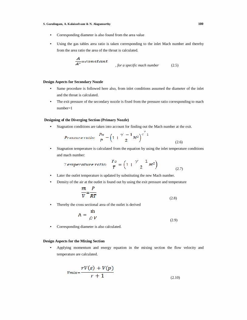
• Corresponding diameter is also found from the area value
• Using the gas tables area ratio is taken corresponding to the inlet Mach number and thereby
from the area ratio the area of the throat is calculated.
, for a specific mach number (2.5)
Design Aspects for Secondary Nozzle
• Same procedure is followed here also, from inlet conditions assumed the diameter of the inlet
and the throat is calculated.
• The exit pressure of the secondary nozzle is fixed from the pressure ratio corresponding to mach
number=1
Designing of the Diverging Section (Primary Nozzle)
• Stagnation conditions are taken into account for finding out the Mach number at the exit.
(2.6)
• Stagnation temperature is calculated from the equation by using the inlet temperature conditions
and mach number:
(2.7)
• Later the outlet temperature is updated by substituting the new Mach number.
• Density of the air at the outlet is found out by using the exit pressure and temperature
(2.8)
• Thereby the cross sectional area of the outlet is derived
(2.9)
• Corresponding diameter is also calculated.
Design Aspects for the Mixing Section
• Applying momentum and energy equation in the mixing section the flow velocity and
temperature are calculated.
(2.10)
101 Experimental Analysis of Jet Ejector by Forced Draught
(2.11)
• Mach no. Before shock wave
M2 = (2.12)
Ratio of actual mixture velocity to the velocity of sound in the mixture, i.e.
(2.13)
• Mach number after shock wave:
(2.14)
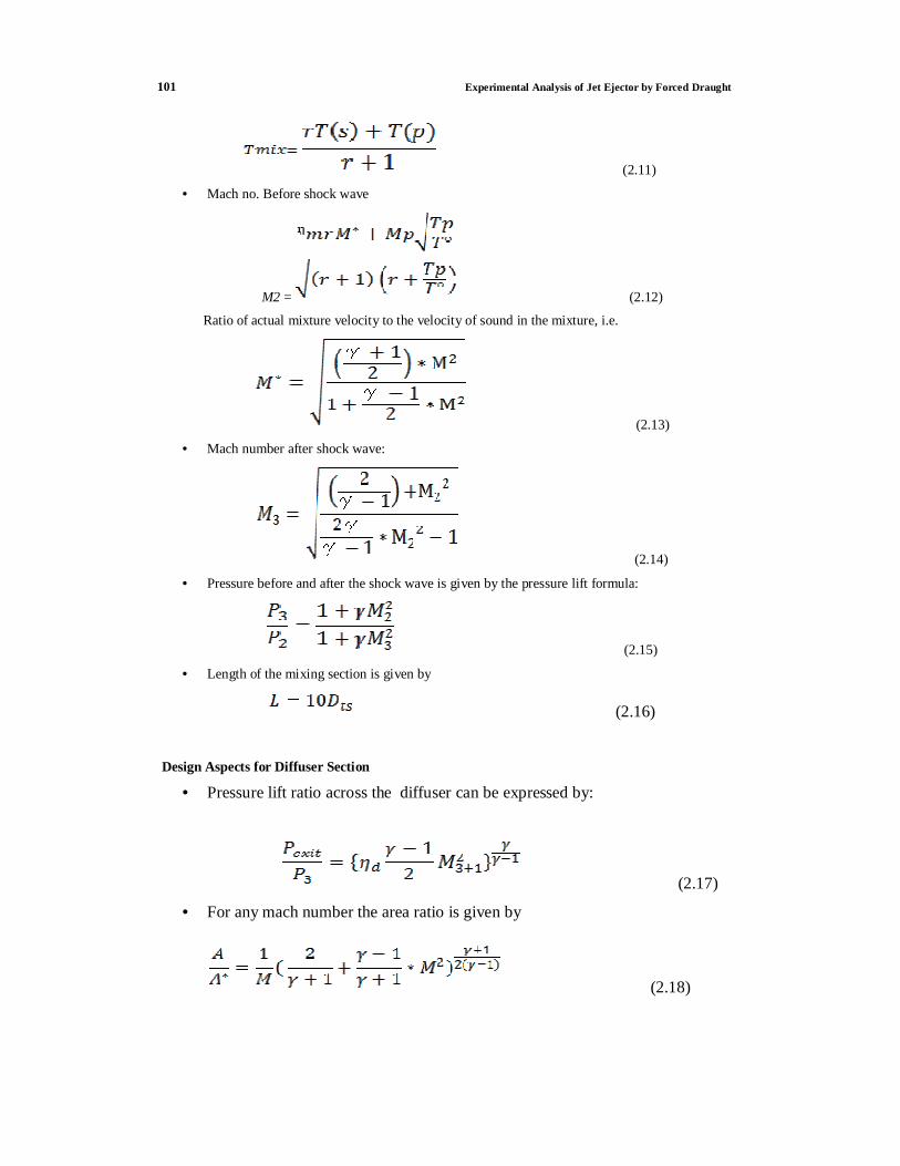
• Pressure before and after the shock wave is given by the pressure lift formula:
(2.15)
• Length of the mixing section is given by
(2.16)
Design Aspects for Diffuser Section
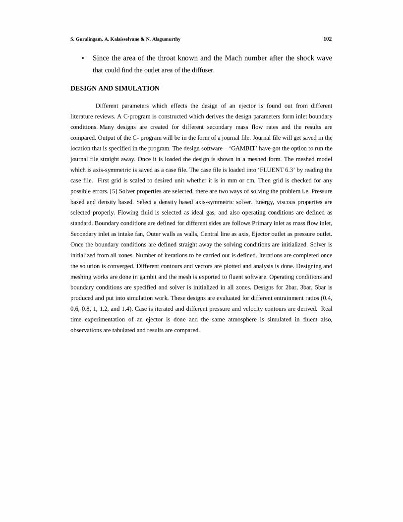
• Pressure lift ratio across the diffuser can be expressed by:
(2.17)
• For any mach number the area ratio is given by
(2.18)
S. Gurulingam, A. Kalaisselvane & N. Alagumurthy 102
• Since the area of the throat known and the Mach number after the shock wave that could find the outlet area of the diffuser.
DESIGN AND SIMULATION
Different parameters which effects the design of an ejector is found out from different
literature reviews. A C-program is constructed which derives the design parameters form inlet boundary
conditions. Many designs are created for different secondary mass flow rates and the results are
compared. Output of the C- program will be in the form of a journal file. Journal file will get saved in the
location that is specified in the program. The design software – ‘GAMBIT’ have got the option to run the
journal file straight away. Once it is loaded the design is shown in a meshed form. The meshed model
which is axis-symmetric is saved as a case file. The case file is loaded into ‘FLUENT 6.3’ by reading the
case file. First grid is scaled to desired unit whether it is in mm or cm. Then grid is checked for any
possible errors. [5] Solver properties are selected, there are two ways of solving the problem i.e. Pressure
based and density based. Select a density based axis-symmetric solver. Energy, viscous properties are
selected properly. Flowing fluid is selected as ideal gas, and also operating conditions are defined as
standard. Boundary conditions are defined for different sides are follows Primary inlet as mass flow inlet,
Secondary inlet as intake fan, Outer walls as walls, Central line as axis, Ejector outlet as pressure outlet.
Once the boundary conditions are defined straight away the solving conditions are initialized. Solver is
initialized from all zones. Number of iterations to be carried out is defined. Iterations are completed once
the solution is converged. Different contours and vectors are plotted and analysis is done. Designing and
meshing works are done in gambit and the mesh is exported to fluent software. Operating conditions and
boundary conditions are specified and solver is initialized in all zones. Designs for 2bar, 3bar, 5bar is
produced and put into simulation work. These designs are evaluated for different entrainment ratios (0.4,
0.6, 0.8, 1, 1.2, and 1.4). Case is iterated and different pressure and velocity contours are derived. Real
time experimentation of an ejector is done and the same atmosphere is simulated in fluent also,
observations are tabulated and results are compared.
103 Experimental Analysis of Jet Ejector by Forced Draught
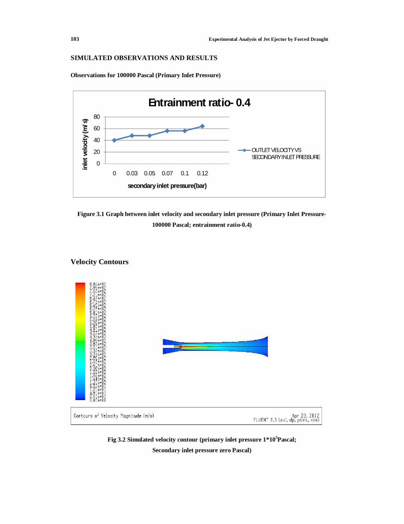
SIMULATED OBSERVATIONS AND RESULTS
Observations for 100000 Pascal (Primary Inlet Pressure)
0
20
40
60
80
0 0.03 0.05 0.07 0.1 0.12
inle
t vel
ocit
y (m
/s)
secondary inlet pressure(bar)
Entrainment ratio- 0.4
OUTLET VELOCITY VS SECONDARY INLET PRESSURE
Figure 3.1 Graph between inlet velocity and secondary inlet pressure (Primary Inlet Pressure-
100000 Pascal; entrainment ratio-0.4)
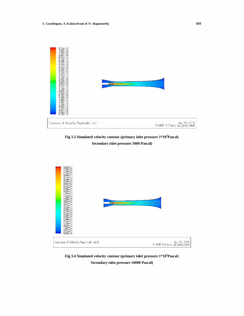
Velocity Contours
Fig 3.2 Simulated velocity contour (primary inlet pressure 1*105Pascal;
Secondary inlet pressure zero Pascal)
S. Gurulingam, A. Kalaisselvane & N. Alagumurthy 104
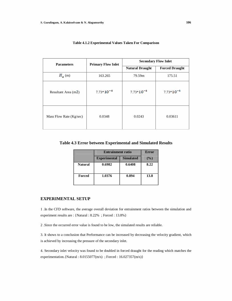
Fig 3.3 Simulated velocity contour (primary inlet pressure 1*105Pascal;
Secondary inlet pressure 5000 Pascal)
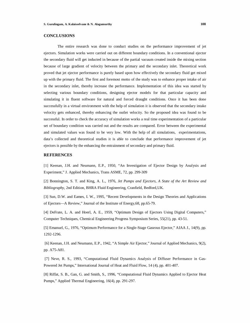
Fig 3.4 Simulated velocity contour (primary inlet pressure 1*105Pascal;
Secondary inlet pressure 10000 Pascal)

105 Experimental Analysis of Jet Ejector by Forced Draught
REAL TIME EXPERIMENTATION
For checking whether the simulations are accurate, adopted an idea to compare one set of
simulation with actual experimentation result a jet ejector is selected and fabricated.
Table 4.1 Simulated Values Taken For Comparison
Intake fan
pressure
Secondary Secondary Intake mass
flow in primary
inlet
Intake mass flow
in secondary
inlet
Entrainment ratio
(bar) inlet outlet (kg/s) (kg/s) x-velocity x-velocity
(m/s) (m/s) Natural 0 8.01551 40.0775 0.04 0.02563 0.64083
Forced 0.03 16.0274 48.0821 0.04 0.03574 0.89359 0.05 24.04103 56.09573 0.04 0.042655 1.066367 0.07 24.04425 56.10325 0.04 0.049638 1.240953 0.1 24.05479 64.1461 0.04 0.060063 1.501583
0.11 32.07935 64.1587 0.04 0.063452 1.5863 0.12 32.08632 72.19421 0.04 0.066788 1.669689
Boundary conditions selected in simulation for comparison with actual
experimentation:
• Selected boundary conditions for Primary inlet:
Pressure: 100000 Pascal, Temperature: 789 K Mass flow rate: 0.04kg/s
• Selected boundary conditions for secondary inlet:
Pressure: (varied), Temperature: 300 K Mass flow rate: (varied according to different
pressures)
RESULTS AND DISCUSSIONS
Comparison between Experimental and Simulated Result
Simulated Values selected for comparison
S. Gurulingam, A. Kalaisselvane & N. Alagumurthy 106
Table 4.1.2 Experimental Values Taken For Comparison
Parameters Primary Flow Inlet Secondary Flow Inlet
Natural Draught Forced Draught
(m) 163.265 79.59m 175.51
Resultant Area (m )
7.73* 7.73* 7.73*
Mass Flow Rate (Kg/sec)
0.0348
0.0243 0.03611
Table 4.3 Error between Experimental and Simulated Results
Entrainment ratio Error
Experimental Simulated (%)
Natural 0.6982 0.6408 8.22
Forced 1.0376 0.894 13.8
EXPERIMENTAL SETUP
1 .In the CFD software, the average overall deviation for entrainment ratios between the simulation and
experiment results are : {Natural : 8.22% ; Forced : 13.8%}
2 .Since the occurred error value is found to be low, the simulated results are reliable.
3. It shows to a conclusion that Performance can be increased by decreasing the velocity gradient, which
is achieved by increasing the pressure of the secondary inlet.
4. Secondary inlet velocity was found to be doubled in forced draught for the reading which matches the
experimentation.{Natural : 8.0155077(m/s) ; Forced : 16.027357(m/s)}

107 Experimental Analysis of Jet Ejector by Forced Draught
5. As a result of forcing the secondary inlet Overall increase in outlet velocity is found to be 16.66%.
{from 40.077 m/s to 48.082m/s}
6. From the simulation studies it was found that only a particular entrainment ratio gives best
performance for an ejector which is designed for a particular capacity.
Fig 4.1 Experimental setup showing ejector connected to the diesel engine outlet
Fig 4.2 Blower used for forced flow experimentation
S. Gurulingam, A. Kalaisselvane & N. Alagumurthy 108
CONCLUSIONS
The entire research was done to conduct studies on the performance improvement of jet
ejectors. Simulation works were carried out on different boundary conditions. In a conventional ejector
the secondary fluid will get inducted in because of the partial vacuum created inside the mixing section
because of large gradient of velocity between the primary and the secondary inlet. Theoretical work
proved that jet ejector performance is purely based upon how effectively the secondary fluid get mixed
up with the primary fluid. The first and foremost motto of the study was to enhance proper intake of air
in the secondary inlet, thereby increase the performance. Implementation of this idea was started by
selecting various boundary conditions, designing ejector models for that particular capacity and
simulating it in fluent software for natural and forced draught conditions. Once it has been done
successfully in a virtual environment with the help of simulation it is observed that the secondary intake
velocity gets enhanced, thereby enhancing the outlet velocity. So the proposed idea was found to be
successful. In order to check the accuracy of simulation works a real time experimentation of a particular
set of boundary condition was carried out and the results are compared. Error between the experimental
and simulated values was found to be very low. With the help of all simulations, experimentations,
data’s collected and theoretical studies it is able to conclude that performance improvement of jet
ejectors is possible by the enhancing the entrainment of secondary and primary fluid.
REFERENCES
[1] Keenan, J.H. and Neumann, E.P., 1950, “An Investigation of Ejector Design by Analysis and
Experiment,” J. Applied Mechanics, Trans ASME, 72, pp. 299-309
[2] Bonnington, S. T. and King, A. L., 1976, Jet Pumps and Ejectors, A State of the Art Review and
Bibliography, 2nd Edition, BHRA Fluid Engineering, Cranfield, Bedford,UK.
[3] Sun, D.W. and Eames, I. W., 1995, “Recent Developments in the Design Theories and Applications
of Ejectors—A Review,” Journal of the Institute of Energy,68, pp.65-79.
[4] DeFrate, L. A. and Hoerl, A. E., 1959, “Optimum Design of Ejectors Using Digital Computers,”
Computer Techniques, Chemical Engineering Progress Symposium Series, 55(21), pp. 43-51.
[5] Emanuel, G., 1976, “Optimum Performance for a Single-Stage Gaseous Ejector,” AIAA J., 14(9), pp.
1292-1296.
[6] Keenan, J.H. and Neumann, E.P., 1942, “A Simple Air Ejector,” Journal of Applied Mechanics, 9(2),
pp. A75-A81.
[7] Neve, R. S., 1993, “Computational Fluid Dynamics Analysis of Diffuser Performance in Gas-
Powered Jet Pumps,” International Journal of Heat and Fluid Flow, 14 (4), pp. 401-407.
[8] Riffat, S. B., Gan, G. and Smith, S., 1996, “Computational Fluid Dynamics Applied to Ejector Heat
Pumps,” Applied Thermal Engineering, 16(4), pp. 291-297.