experimental and analytical seismic evaluation of … and analytical seismic evaluation of ......
TRANSCRIPT

Experimental and Analytical Seismic Evaluation of Concrete Masonry-Infilled Steel
Frames Retrofitted using GFRP Laminates
A Thesis
Submitted to the Faculty
of
Drexel University
by
Wael Wagih El-Dakhakhni
in partial fulfillment of the
requirements for the degree
of
Doctor of Philosophy
September 2002

ii
DEDICATIONS
To my Mother & Father,
To my Brother,
To Lucy & Omar

iii
ACKNOWLEDGMENTS
Praise be to ALLAH with the blessings of Whom the good deeds are fulfilled.
I wish to express my appreciation to my co-advisors Dr. Mohamed Elgaaly and Dr.
Ahmad Hamid for their interest, encouragement and insight during the writing of the thesis.
Special thanks are also due to Dr. Amar Chaker for teaching me interesting topics in structural
dynamics and earthquake engineering.
For his unparalleled assistance during the experimental work, I would like to express my
deepest gratitude to Mr. Xiaobo Wang. The assistance of Mr. Gregory Hilley and Mr. Charles
Williams is also acknowledged. Dr. Tamer El-Raghy, and Dr. Sherif Ibrahim are appreciated for
their help, encouragement and suggestions.
The financial support of the National Science Foundation, (Grant number CMS-
9730646), and Drexel University is gratefully acknowledged.
I will always be indebted to my late father and mentor Professor Wagih El-Dakhakhni,
who made me fall in love with Structural Engineering. I am also very grateful to Professor
Mohamed Al Hashemy for teaching me reinforced concrete structures design during my senior
year and to Professor El Mostafa Hegazy who first introduced me to the challenging science of
earthquake engineering.
At last but not the least, I thank my mother and my brother for everything they did, and
still doing for me. I am also thankful to my wife, Lucy, for her unwavering patience,
understanding, and encouragement and to my son Omar for keeping me accompanied during the
writing of the thesis.

iv
TABLE OF CONTENTS
List of Tables ...................................................................................................................viii
List of Figures ....................................................................................................................ix
Abstract ............................................................................................................................xiii
Chapter 1-Introduction ........................................................................................................1
1.1 Background ..................................................................................................1
1.2 Fiber Reinforced Polymers (FRPs)..............................................................5
1.3 Research Objectives .....................................................................................7
1.4 Organization of the Dissertation..................................................................8
Chapter 2-Literature Review..............................................................................................12
2.1 Introduction............................................................................................... 12
2.2 Previous Research on Masonry Infilled Frames ........................................13
2.3 The Use of Masonry Infill Walls as a Retrofitting Technique ...................27
2.4 Retrofitting Techniques for Masonry Structures .......................................30
2.5 Summary and Conclusion..........................................................................35
Chapter 3- Testing of Wall Subassemblages Retrofitted with GFRP Laminates ..............41
3.1 Introduction ...............................................................................................41
3.2 Experimental Program ...............................................................................42
3.3 Preparation of Test Specimens ...................................................................43
3.4 Test Results and Discussion.......................................................................44

v
3.4.1 specimens behavior under axial compression...................................44
3.4.1.1 Stress-Strain Behavior .......................................................44
3.4.1.2 Failure Modes of the Bare Specimens ...............................45
3.4.1.3 Failure Modes of the Strengthened Specimens..................46
3.4.2 specimens behavior under Direct Shear............................................48
3.4.2.1 Failure Modes of the Bare Specimens ...............................48
3.4.2.2 Failure Modes of the Strengthened Specimens..................49
3.5 Conclusions ................................................................................................51
Chapter 4-Testing of Concrete Masonry-Infilled Steel Frames.........................................63
4.1 Introduction................................................................................................63
4.2 Behavior of Masonry Infill Walls ..............................................................65
4.3 Experimental Program ...............................................................................66
4.4 Material Properties .....................................................................................67
4.5 Retrofitting Scheme ...................................................................................68
4.6 Lateral Load Testing ..................................................................................70
4.6.1 Test Setup and Instrumentation .......................................................70
4.6.2 Displacement Protocols ....................................................................71
4.6.3 Experimental Results ........................................................................72
4.6.3.1 SP-1 Behavior ....................................................................73
4.6.3.2 SP-2 Behavior ....................................................................74
4.6.3.3 SP-3 Behavior ....................................................................75
4.6.3.4 SP-4 Behavior ....................................................................76
4.6.3.5 SP-5 Behavior ...................................................................78

vi
4.6.3.6 SP-6 Behavior ....................................................................79
4.6.4 Global Response ...............................................................................81
4.6.5 Local Response .................................................................................82
4.7 Summary and Conclusions ........................................................................84
Chapter 5-Modeling, System Identification and Design Methodology ...........................103
5.1 Introduction .............................................................................................103
5.2 Failure Modes of Infilled Frames ............................................................105
5.3 Conceptual Design of Retrofitted Masonry Infill Walls ..........................107
5.4 Development of CMISF Model for CC Mode .........................................111
5.4.1 Steel Frame Model..........................................................................112
5.4.2 Infill Wall Model ............................................................................114
5.5 Eliminating the DC Mode .......................................................................122
5.6 Eliminating the SS Mode ........................................................................124
5.7 Eliminating the FF Mode .........................................................................126
5.8 Modeling Test Specimens ........................................................................129
5.9 Conclusions .............................................................................................131
Chapter 6-Summary, Conclusions and Recommendations .............................................143
6.1 Summary .................................................................................................143
6.2 Conclusions .............................................................................................145
6.3 Recommendations for Future Work ........................................................147
List of References ............................................................................................................149
Appendix A: Notation..................................................................................................... 156
Appendix B: Photographs ............................................................................................... 159

vii
Appendix C: Numerical Procedures ............................................................................... 163
Vita...................................................................................................................................165
viii
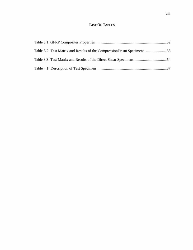
LIST OF TABLES
Table 3.1: GFRP Composites Properties ...........................................................................52
Table 3.2: Test Matrix and Results of the Compression Prism Specimens ......................53
Table 3.3: Test Matrix and Results of the Direct Shear Specimens .................................54
Table 4.1: Description of Test Specimen...........................................................................87

ix
LIST OF FIGURES
Figure 1.1: Possible Effects of the Infills Depending on Earthquake Response
Spectrum ..........................................................................................................10
Figure 1.2: a) Influence of partial height infill increasing column shear force (1985 Chilean earthquake). Courtesy of Earthquake Spectra and Earthquake Engineering Research Institute); b) Failure of lower level of masonry- infilled reinforced concrete frame (1990 Philippine earthquake) (Courtesy of EQE Engineering Inc.) ............................................10
Figure 1.3: Failure of URM Walls (Turkey, 1999) ; a) Out-of-Plane Failure,
b) In-Plane Failure, c) Combined Failure ..........................................................11 Figure 1.4: Micro Structure of FRP Composites ...............................................................11 Figure 2.1: Effective Diagonal Compression Strut ............................................................37 Figure 2.2: The Infilled Frame Model Proposed by Seah (1998) ......................................37 Figure 2.3: Load-Deflection Behavior of a Specimen Modeled by Seah (1998) ..............38 Figure 2.4: Energy Dissipation in Each Component of the Infilled Frames
Structure Investigated by Kappos et al. (2000)................................................38 Figure 2.5: The Infilled Frame Model Proposed by El-Dakhakhni (2000) .......................39 Figure 2.6: The FRP Retrofitted Shear Specimen investigated by
Ehsani et al. (1997) ..........................................................................................39 Figure 2.7: The Steel Strips Retrofiting Technique Suggested by Taghdi et al.
(2000) for URM Walls .....................................................................................40 Figure 2.8: The GFRP Effect on The Diagonally Loaded Masonry Infilled Steel
Frames Tested by Hakam (2000).....................................................................40 Figure 3.1: a) Test Specimens as Subassemblages of URM Wall; b) CN
Specimen; c) CP Specimen; d) DS Specimen; and e) DS Specimen Construction.....................................................................................................55
Figure 3.2: Strengthened Specimen Name Assignment Notation .....................................55 Figure 3.3: Stress-Strain Relation of CN-W-1,CN-W-2, CN-S-P and CN-Bare
Specimens ........................................................................................................56
x
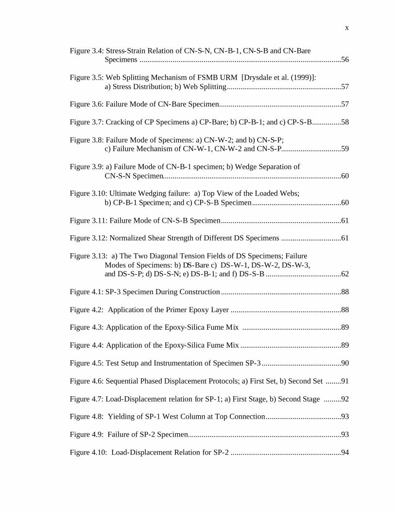
Figure 3.4: Stress-Strain Relation of CN-S-N, CN-B-1, CN-S-B and CN-Bare Specimens ........................................................................................................56
Figure 3.5: Web Splitting Mechanism of FSMB URM [Drysdale et al. (1999)]: a) Stress Distribution; b) Web Splitting...........................................................57
Figure 3.6: Failure Mode of CN-Bare Specimen...............................................................57 Figure 3.7: Cracking of CP Specimens a) CP-Bare; b) CP-B-1; and c) CP-S-B...............58 Figure 3.8: Failure Mode of Specimens: a) CN-W-2; and b) CN-S-P;
c) Failure Mechanism of CN-W-1, CN-W-2 and CN-S-P...............................59
Figure 3.9: a) Failure Mode of CN-B-1 specimen; b) Wedge Separation of CN-S-N Specimen............................................................................................60
Figure 3.10: Ultimate Wedging failure: a) Top View of the Loaded Webs;
b) CP-B-1 Specimen; and c) CP-S-B Specimen..............................................60 Figure 3.11: Failure Mode of CN-S-B Specimen..............................................................61 Figure 3.12: Normalized Shear Strength of Different DS Specimens ...............................61 Figure 3.13: a) The Two Diagonal Tension Fields of DS Specimens; Failure
Modes of Specimens: b) DS-Bare c) DS-W-1, DS-W-2, DS-W-3, and DS-S-P; d) DS-S-N; e) DS-B-1; and f) DS-S-B .......................................62
Figure 4.1: SP-3 Specimen During Construction ..............................................................88 Figure 4.2: Application of the Primer Epoxy Layer .........................................................88 Figure 4.3: Application of the Epoxy-Silica Fume Mix ...................................................89 Figure 4.4: Application of the Epoxy-Silica Fume Mix ....................................................89 Figure 4.5: Test Setup and Instrumentation of Specimen SP-3 .........................................90 Figure 4.6: Sequential Phased Displacement Protocols; a) First Set, b) Second Set ........91 Figure 4.7: Load-Displacement relation for SP-1; a) First Stage, b) Second Stage .........92 Figure 4.8: Yielding of SP-1 West Column at Top Connection.......................................93 Figure 4.9: Failure of SP-2 Specimen...............................................................................93 Figure 4.10: Load-Displacement Relation for SP-2 .........................................................94
xi
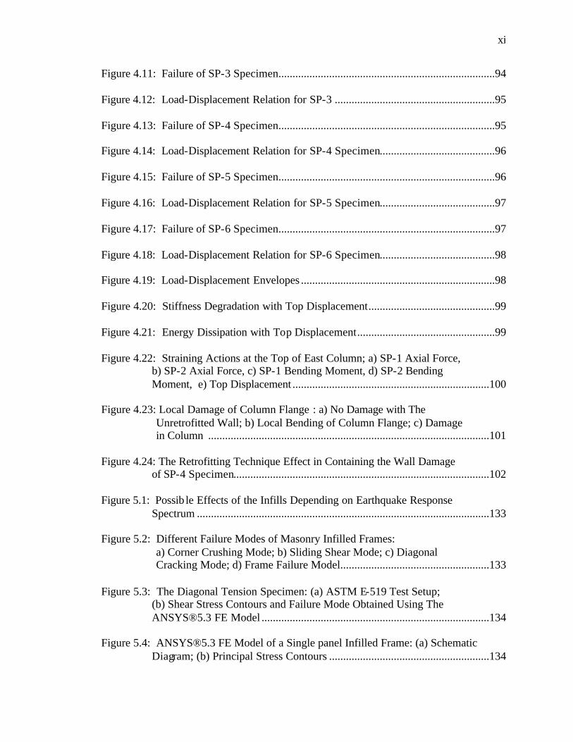
Figure 4.11: Failure of SP-3 Specimen.............................................................................94 Figure 4.12: Load-Displacement Relation for SP-3 .........................................................95 Figure 4.13: Failure of SP-4 Specimen.............................................................................95 Figure 4.14: Load-Displacement Relation for SP-4 Specimen.........................................96 Figure 4.15: Failure of SP-5 Specimen.............................................................................96 Figure 4.16: Load-Displacement Relation for SP-5 Specimen.........................................97 Figure 4.17: Failure of SP-6 Specimen.............................................................................97 Figure 4.18: Load-Displacement Relation for SP-6 Specimen.........................................98 Figure 4.19: Load-Displacement Envelopes .....................................................................98 Figure 4.20: Stiffness Degradation with Top Displacement.............................................99 Figure 4.21: Energy Dissipation with Top Displacement.................................................99 Figure 4.22: Straining Actions at the Top of East Column; a) SP-1 Axial Force,
b) SP-2 Axial Force, c) SP-1 Bending Moment, d) SP-2 Bending Moment, e) Top Displacement ......................................................................100
Figure 4.23: Local Damage of Column Flange : a) No Damage with The
Unretrofitted Wall; b) Local Bending of Column Flange; c) Damage in Column ....................................................................................................101
Figure 4.24: The Retrofitting Technique Effect in Containing the Wall Damage
of SP-4 Specimen...........................................................................................102
Figure 5.1: Possib le Effects of the Infills Depending on Earthquake Response Spectrum ........................................................................................................133
Figure 5.2: Different Failure Modes of Masonry Infilled Frames: a) Corner Crushing Mode; b) Sliding Shear Mode; c) Diagonal Cracking Mode; d) Frame Failure Model.....................................................133
Figure 5.3: The Diagonal Tension Specimen: (a) ASTM E-519 Test Setup;
(b) Shear Stress Contours and Failure Mode Obtained Using The ANSYS®5.3 FE Model .................................................................................134
Figure 5.4: ANSYS®5.3 FE Model of a Single panel Infilled Frame: (a) Schematic
Diagram; (b) Principal Stress Contours .........................................................134

xii
Figure 5.5: The Infill Wall Contact Lengths....................................................................135 Figure 5.6: The Beam-Column Connection Material Model Behavior ...........................135 Figure 5.7: Simplified Piecewise-Linear Relations for the Diagonal Strut:
(a) Stress-Strain Relation; (b) Force-Deformation Relation ......................136 Figure 5.8: The Proposed CMISF Model ........................................................................136 Figure 5.9: Tensile Stresses Resulting in The Diagonal Cracking: a) Elastic
Model; b) Ultimate Limit Model ...................................................................137 Figure 5.10: Knee Brace Effect of the Frame Caused by the SS Mode...........................137 Figure 5.11: Bending Moment Diagrams for a Different Bays in Multi-Story
Infilled Frame Building..................................................................................138 Figure 5.12: Different Modeling Levels of the Infill Wall within CMISF
Buildings: a) Global Model, b) Intermediate Model, c) Local Model...........139
Figure 5.13: Behavior of Bare Frame Model Joints: a) Top Joint, b) Bottom Joint ........140 Figure 5.14: Specimen SP-1 Model with the Test Results ..............................................140
Figure 5.15: Behavior of Specimen SP-2 Model Diagonal Strut: a) Stress-Strain
Relation, b) Force-Deformation Relation ......................................................141 Figure 5.16: Behavior of Specimen SP-4 Model Diagonal Strut: a) Stress-Strain
Relation, b) Force-Deformation Relation ......................................................141
Figure 5.17: Specimen SP-2 Model with the Test Results ..............................................142 Figure 5.18: Specimen SP-4 Model with the Test Results ..............................................142 Figure B.1: Assemblages Construction............................................................................159 Figure B.2: Walls Construction .......................................................................................159 Figure B.3: SP-2 Specimen Failure .................................................................................160 Figure B.4: SP-6 Specimen Failure .................................................................................160 Figure B.5: SP-3 Specimen Failure .................................................................................161 Figure B.6: SP-5 Specimen Failure .................................................................................162

xiii
ABSTRACT
Experimental and Analytical Seismic Evaluation of Concrete Masonry-Infilled Steel Frames Retrofitted using GFRP Laminates
Wael Wagih Eldakhakhni, P.E. Mohamed Elgaaly, Sc.D., P.E. and Ahmad Hamid, Ph.D., P.E.
The study conducted herein focuses on investigating the retrofitting effect of face
shell mortar bedding (FSMB) hollow concrete masonry-infilled steel frames (CMISF)
subjected to in-plane lateral loads using glass fiber reinforced plastic (GFRP) laminates
that are epoxy-bonded to the exterior faces of the infill walls. The study involves three
main phases, the first phase studies the in-plane behavior of unreinforced masonry
(URM) wall subassemblages strengthened with different GFRP composite laminates. A
total of fifty-seven URM assemblages were tested under different loading conditions.
Parameters such as the type of fibers, the number of plies, and the fibers orientation were
investigated. Results showed that the application of GFRP laminates on URM has a great
influence on strength, post peak behavior, as well as failure modes. An increase of 90%
for compressive strength was achieved using the GFRP laminates and the shear strength
increased by fourteen folds.
The second phase focuses on enhancing the in-plane seismic behavior of URM
infill walls when subjected to displacement controlled cyclic loading. Six full-scale single
story single bay steel frames with different wall configurations were tested. The
retrofitting technique using GFRP laminates aims at creating an engineered infill wall
with a well defined failure mode and a stable post peak behavior as well as containing the
hazardous URM damage and preventing catastrophic failure. Results showed that the
GFRP prevented both shear and tension cracking by supplying the required tensile
strength. The GFRP also increased the lateral load capacity and enhanced the post peak
behavior by means of stabilizing the masonry face shell and preventing its out-of-plane

xiv
spalling. The stabilizing allows the wall to carry more loads and prevents sudden drop in
the load carrying capacity.
The third phase of the study presents an analytical model proposed for the
analysis of the unretrofitted and GFRP-retrofitted masonry infilled frames. In this
method, each masonry wall was replaced with a nonlinear, compression-only, diagonal
strut that estimates the stiffness and the lateral load capacity of CMISF failing in corner
crushing (CC) mode. The diagonal strut force-deformation characteristics were based on
the orthotropic behavior of the masonry wall. A proposed method for designing the
GFRP retrofitted walls in order to prevent various failure modes is also presented.
1
CHAPTER 1: INTRODUCTION
1.1 BACKGROUND
Unreinforced masonry (URM) buildings represent a large portion of the buildings
around the world and in the United States especially in the eastern part of the country.
Masonry infill walls can be found as interior and exterior partitions in reinforced concrete
and steel frame structures. Since they are normally considered as architectural elements,
the infill walls presence is often ignored by structural engineers. However, even though
they are considered nonstructural, they tend to interact with the surrounding frame when
the structure is subjected to strong earthquake loads, the resulting system is referred to as
an infilled frame.
Considering only the strengthening effect of the infills and assuming that they will
only increase the overall lateral load capacity, and therefore must always be beneficial to
seismic performance, is a common misconception. In fact there are numerous examples
of earthquake damage that can be traced to structural modification of the bare frame by
the so-called nonstructural masonry partitions or the infill walls.
The earthquake damage of the infilled frame structures usually results from
ignoring the stiffening effect of the infill, which was reported to increase the stiffness of
the bare frame 4 to 20 times, [Comite Euro-International Du Beton, (1996)]. A similar
effect is expected in the structure as a whole, depending, however, on both the total
number of infill walls in both directions and the thickness of the infills. Obviously this
increased lateral stiffness would result in a decreased natural period of vibration Tn of the

2
infilled structure, when compared to the Tn value of the respective bare structure. Due to
the decreased natural period of the infilled structure, the expected seismic response is also
affected, depending on the characteristics of the earthquakes, which may occur. In fact as
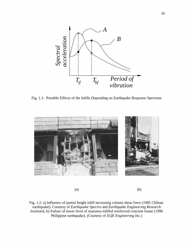
shown in Fig. 1.1 (where Tif is the initial period of vibration of the infilled frame, and Tbf
is that of the bare frame), for an earthquake having a response spectrum following curve
A, the total base shear on the structure will increase. Alternatively, for earthquake B, the
base shear would decrease because of the addition of the infill walls.
If higher seismic loads are attracted, and the wall is overstressed it fails either
wholly or partially. Failing partially will result in modifying the natural period of the
structure. If the wall is wholly damaged, then the high forces previously attracted and
carried by the stiff, and strong infilled frame, will be suddenly transferred to the more
flexible, and weak bare frame after the infill is fully damaged. Figure 1.2-a shows the
consequences of ignoring the stiffening effect of the partial height masonry infill causing
a short column failure mechanism. Figure 1.2-b shows another example of failure of a
framed structure, the stiffening affect of the infill attracted higher seismic loads resulting
in failure of the infill followed by failure of the frame columns.
Because of the complexity of the problem, as will be shown later in the following
chapters, and the absence of a realistic, yet simple analytical model, it is not surprising
that the effect of masonry infill walls is often neglected in the nonlinear analysis of
building structures. Such an assumption may lead to substantial inaccuracy in predicting
the lateral stiffness, strength, and ductility of the structure. It will also lead to
uneconomical design of the frame since the strength and stiffness demand of the frame
could be largely reduced. Some techniques of isolating the infill wall from the

3
surrounding frame so that the frame would not come into contact with the wall under
in-plane loading create another complicated problem of detailing the wall- to-frame
connection to prevent out-of-plane instability due to lateral loads, yet not allowing them
to interact in-plane. There is also the possibility that during an earthquake, the wall could
impact against the frame, inducing high moments and shear in the columns and lead to a
short column shear failure.
In general, URM infill walls have a poor performance record even in moderate
earthquakes. Their behavior is usually brittle with little or no ductility and both structural
and nonstructural parts suffer various types of damages ranging from invisible cracking
to crushing and eventually disintegration. This behavior is due to the rapid degradation of
stiffness, strength and energy dissipation capacity, which results from the brittle sudden
damage of the masonry wall. This, constitutes a major source of hazard during seismic
events and can create a major seismic performance problem facing earthquake
engineering today.
Organizations such as The Masonry Society (TMS) and the Federal Emergency
Management Agency (FEMA), have identified that failures of URM walls result in most
of the material damage and loss of human life. This was evident from the post-earthquake
observations in Northridge, California (1994) and Turkey (1999). Figure 1.3 illustrates
the collapse of URM walls due to out-of-plane and in-plane loads after the 1999 Turkey
earthquake. Note the debris at the bottom, which during an earthquake is a potential
threat to bystanders.
Under the URM Building Law of California, passed in 1986, approximately
25,500 URM buildings were inventoried throughout the state. Even though, this number

4
is a relatively small percentage of the building inventory in California, it includes many
cultural icons and historical resources. The building evaluation showed that 96% of the
buildings needed to be retrofitted, which would result in approximately $4 billion in
retrofit expenditures. To date, it has been estimated that only half of the owners have
taken remedial actions, which may attributed to high retrofitting costs. Thereby, the
development of effective and affordable retrofitting techniques for masonry elements is
an urgent need.
Conventional retrofitting techniques can be classified according to the problem to
be addressed: damage repair or structure upgrading. For damage repair in the form of
cracks, the following methods can be used:
• Filling of cracks and voids by injecting epoxy or grout.
• Stitching of large cracks and weak areas with metallic or brick elements.
For strengthening or upgrading, the following procedures are available:
• Grout injection of hollow masonry units with non-shrink portland cement grout or
epoxy grout to strengthen or stiffen the wall.
• Construction of an additional wythe to increase the axial and flexural strength.
• Post-tensioning of an existing construction.
• External reinforcement with steel plates and angles.
• Surface coating with reinforced cement paste or shotcrete, such as a welded mesh.
Most of these methods have proven to be impractical, labor intensive, add considerable
mass, and cause significant impact on the occupant, all resulting in very high costs. In
short, these method as have been proven to be impractical, too costly and restricted in use
to certain types of structures. This may lead to a ‘‘do nothing’’ choice, in which the

5
owner decides that the risk of economic loss and occupant injury does not justify the
significant cost of strengthening.
1.2 FIBER REINFORCE POLYMERS (FRPS)
Fiber Reinforced Polymer (FRP) is a composite material composed of matrix of
polymeric material reinforced by uni-directional or multi-directional fibers, usually 3 to 5
microns in diameter, (see Fig 1.4) placed in a resin matrix, polymer, and hence stems the
name “Fiber Reinforced Polymers” or FRP and in the case of structural applications, at
least one of the constituent materials must be a continuous phase supported by a
stabilizing matrix. For the special class of matrix materials utilized in structural
engineering applications (i.e. the thermosetting polymers), the continuous fiber will
usually be stiffer and stronger than the matrix. The resin matrix binds the fibers together,
allows load transfer between fibers and it also protects the fibers from environment.
The FRP are mechanically different from steel in a sense that it is anisotropic, linear-
elastic and it is usually of higher strength with a lower modulus of elasticity than steel.
The FRP have desirable physical properties over steel, like corrosion resistance, high
strength-to-weight ratio, high fatigue resistance, and dimensional stability. The FRP also
has the disadvantages of the susceptibility to moisture and chemicals, the loss of
properties at high temperatures, as in the case of fire, and the damage from Ultra-Violet
light.
The production of FRP started since the 1940’s, where it was used in variety of
industries, such as aerospace, automotive, shipbuilding, chemical processing, etc., for
many years. Their application in civil engineering, however, has been very limited. Their
6
high strength-to-weight ratio and excellent resistance to corrosion make them attractive
material for structural applications. Presently, several types of FRP materials have been
considered for repair and retrofit of concrete and masonry structures, among them are the
glass fiber-reinforced polymers “GFRP”, carbon fiber-reinforced polymers “CFRP”, and
aramid fiber-reinforced polymers “AFRP”. Glass has been the predominant fiber for
many civil engineering applications because of the economical balance of cost and
strength properties.
Although the FRP can be used as a structural stand-alone materia l like the
structural steel shapes or reinforcement bars for new reinforced concrete or masonry
structures, yet its most extensive use to-date is to retrofit existing structures in the form of
bonded laminates. The laminates are made by stacking a number of thin layers of fibers
and matrix and consolidate them into the desired thickness. Fiber orientation in each layer
as well as the stacking sequence of the various layers can be controlled to generate a
range of physical and mechanical properties. Laminates are used either in the form of dry
plates or wet lay-up of a single lamina or multiple laminates. The plates are to be bonded
to the surface using the appropriate adhesive, whereas the wet lay-up involves wetting
(impregnating) the fabric at the time of installation in-situ with the appropriate polymer,
in this case the polymer serves both as a binding matrix as well as bonding the FRP to the
surface of the structure.
The most important characteristics of a strengthening work are the predominance
of labor and shutdown costs, time, site constraints and long-term durability. In addition to
their outstanding mechanical properties, the advantages of FRP composites versus
conventional materials for strengthening of structural and nonstructural elements include

7
lower installation costs, improved corrosion resistance, onsite flexibility of use, and
minimum changes in the member size after repair. From the architectural point of view,
this constitutes a huge advantage for the FRPs against traditional strengthening
techniques, because the use of conventional methods may violate the aesthetics of
building facades and they may intrude on usable space adjacent to the strengthened
components. More importantly, from the structural point of view, the dynamic properties
of the structure remain unchanged because there is little addition of weight and stiffness.
Any alteration to the aforementioned properties would typically result in an increase in
seismic forces. Additionally, the ease with which FRP composites can be installed on the
exterior (or interior) of a masonry wall makes this form of strengthening attractive to the
owner, considering both reduced installation cost and down-time.
1.3 RESEARCH OBJECTIVES
Due to the rapid development of the analysis of multistory frames, and the evolution
of new seismic design philosophies, such as the capacity design concept suggested by
Paulay and Priestley (1992), including the infill walls in both the analysis and the design
stages is much more significant nowadays than in the past. Therefore, there is a demand
for a simple, yet, accurate analytical technique for the design of new infilled frame
structures. An urgent need for this technique also stems out from the ever- increasing
demand for the evaluation of existing infilled frames for seismic assessment and
retrofitting purposes in order to conform to new seismic codes.
A part of this study aims towards developing a simple analytical technique for
modeling the infilled frame structure, and overcoming Axley and Bertero’s statement

8
(1979) “Infilled frame structural systems have resisted analytical modeling”. While
developing this modeling technique, it was kept in mind to present a simple method of
predicting the stiffness as well as the ultimate load capacity of masonry infilled steel
frames. The method is easy enough to be included during the design process of such
systems using the simplest available resources in the design offices. The technique should
also be systematic in order to produce design aids and to be used to develop a conceptual
approach of the analysis and the design of such systems.
Another aim of this study is to show experimentally the effect of retrofitting the
masonry using FRP, in order to enhance both the strength and the ductility demands for
these structures and to eliminate brittle failure modes as well as increasing the confidence
in the modeling technique by limiting the number of failure modes. This technique is
expected also to facilitate the upgrade of existing building to conform to the new seismic
codes and eliminating the need to the more expensive and time consuming retrofitting
techniques, or in many cases, the total demolition of the structure.
1.4 ORGANIZATION OF THE DISSERTATION
This dissertation is organized according to the stages followed for the
development of the investigation. Thus, Chapter One introduces a general statement of
the problem and the objectives of this research. Chapter Two reviews the available
literature discussing various studies conducted on infilled frames, including modeling and
evaluation of different parameters controlling their behavior. The chapter also includes a
literature survey on the different techniques used for retrofitting masonry structures
including the use of FRP as well as highlighting the structural application of the FRP in

9
repairing/ strengthening/ retrofitting of reinforced concrete structures. Chapter Three
describes the first phase of the experimental program conducted to evaluate the behavior
of hollow concrete masonry wall subassemblages, with and without FRP retrofitting. In
Chapter Three, the properties of the FRP materials as well as the constituent materials are
presented. The effect of different GFRP composites on wall subassemblages is also
investigated in order to determine the most suitable laminate to retrofit the full-scale wall.
Chapter Four gives the details of the second phase of the experimental program in this
study, namely, the testing of the full-scale masonry infilled steel frames under quasi-static
loading, for both unretrofitted and retrofitted masonry walls. The test results in both
Chapters Three and Four are interpreted and mechanisms of failure are identified.
Assumptions and expressions used for the development of analytical models are
presented. The analytical values were confronted with the experimental values. Chapter
Five presents a rational, simple, and easy to use analytical approach to generate the
envelope of the load-deflection relation of the infill walls following a step-by-step logical
approximations based on and supported by analytical and experimental observations.
Chapter Five also presents provisional design guidelines for shear and tensile
strengthening of URM infill walls with FRP composites. Finally, Chapter Six provides
conclusions and recommendations for future work in the area of masonry strengthening
with FRP composites.
10
Fig. 1.1: Possible Effects of the Infills Depending on Earthquake Response Spectrum
(a) (b)
Fig. 1.2: a) Influence of partial height infill increasing column shear force (1985 Chilean earthquake). Courtesy of Earthquake Spectra and Earthquake Engineering Research
Institute); b) Failure of lower level of masonry- infilled reinforced concrete frame (1990 Philippine earthquake). (Courtesy of EQE Engineering Inc.)
acce
lera
tion
Spec
tral
Tif bfT
A
Period ofvibration
B

11
(a) (b) (c)
Fig. 1.3: Failure of URM Walls (Turkey, 1999) ; a) Out-of-Plane Failure, b) In-Plane Failure, c) Combined Failure
Fig. 1.4: Micro Structure of FRP Composites

12
CHAPTER 2: LITERATURE REVIEW
2.1 INTRODUCTION The effect of masonry infilled walls in changing the stiffness, ultimate capacity
and failure mode of framed structures has been one of the most interesting research topics
in the last five decades. The first report on the contribution of masonry infill in resisting
lateral loads came after the completion of the Empire State Building in New York. As
reported by Rathbun (1938); during a storm with a wind gust exceeding 90 mph, diagonal
cracks appeared in a number of masonry infill partitions on the twenty-ninth and forty-
first floors. Separation cracks between the frame and the masonry walls were also noted.
Incidentally, strain gages attached to the steel frame did not register any strains prior to
cracking of the masonry despite the presence of strong wind. This was explained by the
high rigidity of the masonry infill wall, which prevented distortion of the steel frame.
When the walls were stressed beyond their cracking capacity, there was a marked
decrease in the stiffnesses of the infills. Consequently, the strain gages began to register
strains indicating that the steel frame had begun to participate in resisting the wind load.
Even though it was cracked, the masonry infills confined within the steel frames
continued to offer strong lateral load resistance. Ever since this incident and up-to-date,
the behavior of infilled frames has been the subject of investigations conducted by
researchers throughout the world. Different approaches had been adopted starting from
simple strength of materials approach, passing through trials to match experimental
results using simple models. Methods based on the theory of elasticity, equilibrium and
energy approach, plastic analysis and finally finite element (FE) analysis were also used.

13
The literature survey in this study is divided into two sections. The first section
highlights various experimental and theoretical studies conducted to date in the area of
masonry infilled steel and RC frames with emphasis on the conclusions reached. The
second section shows some of the retrofitting techniques of masonry structures.
2.2 PREVIOUS RESEARCH ON MASONRY INFILLED FRAMES
The first published research on infilled RC frames subjected to racking load was
by Polyakov (1956). This publication reported a test program carried out from 1948 to
1953. In order to determine the racking strength of infilled frames, Polyakov performed a
number of large-scale tests including square as well as rectangular frames. Parameters
investigated included the effects of the type of masonry units, mortar mixes, admixtures,
methods of load application (monotonic or cyclic), and the effect of openings. Polyakov
described the history of infilled frame behavior subjected to racking load. First, the
masonry infill and the members of the structural frame behave monolithically until
separation cracks between the infill and the frame develop around the perimeter of the
infill- to-frame interface except for small regions at the two diagonally opposite corners.
Secondly, the compression diagonal starts to shorten and the tension diagonal to lengthen
until the masonry infill cracks along the compression diagonal in a step-wise manner
through mortar head and bed joints. The structural assemblage continues to resist an
increasing load in spite of the diagonal cracks, and the diagonal cracks continue to widen
and new cracks appear. The system is considered to have reached failure after the
appearance of large cracks. In a subsequent paper, Polyakov (1960) described

14
experiments performed on a three-bay, three-story model steel frame infilled with
masonry. Based on observation of the infill boundary separation, he suggested that the
infilled frame system is equivalent to a braced frame with a compression diagonal strut
replacing the infill wall.
In the same period, experimental work was conducted by Thomas (1953) and
Wood (1958) in the United Kingdom and test results provided ample testimony that a
relatively weak infill can contribute significantly to the stiffness and strength of an
otherwise flexible frame. Sachanski (1960) performed tests on model and prototype
infilled frames. Based on his test results, he proposed an analytical model in which he
analyzed contact forces between the frame and the infill by assuming their mutual bond
to be replaced by thirty redundant reactions. The forces were determined by forming and
solving the equations for the compatibility of displacements of the frame and the infill.
He treated the infill as an elastic membrane and stiffness coefficients of the infill were
determined by integrating the stresses determined by using a finite difference technique.
Having found the contact forces, he then proposed a stress function for the stress analysis
of the infill. It should be pointed out that the theoretical approach of Sachanski can only
be applied to an integral infill frame where separation between the infill and the frame is
prevented. Additionally, the infill was assumed to be isotropic, homogeneous, and elastic
and these assumptions are not applicable for the non-homogeneous and anisotropic
masonry infills.

15
Holmes (1961) proposed a method for predicting the deformations and strength of
infilled frames based on the equivalent diagonal strut concept. He assumed that the infill
wall acts as a diagonal compression strut, as shown in Fig. 2.1, of the same thickness and
elastic modulus as the infill with a width equal to one-third the diagonal length. He also
concluded that, at the infill failure, the lateral deflection of the infilled frame is small
compared to the deflection of the corresponding bare frame. Also, the frame members
remained elastic up to the failure load. By equating the elastic deformation of the frame
diagonal to the shortening of the equivalent diagonal strut at failure, Holmes derived an
equation to determine the ultimate lateral load capacity, namely,
θθθ
CosAf + C
I
I+1h
d’e24EI = H c
0
3
c
osCot
(2.1)
where, H is the horizontal load at failure, I is the moment of inertia of the column of the
frame, I0 is the moment of inertia of the beam of the frame, E is the modulus of elasticity
of frame members, ce' is the uniaxial compressive strain of the infill material at failure, h
is the height of the infill, d is the diagonal length of the infill, θ is the angle of
inclination of the diagonal strut to the horizontal, A is the sectional area of the equivalent
diagonal strut and f c is the ultimate compressive strength of the equivalent diagonal
strut. Holmes showed that a value of td 3 , where t and d are the thickness and diagonal
length of the infill, respectively, best represents the value of A for strength prediction.
However, the analytical predictions of deflection at ultimate load were generally lower
than those measured experimentally. Later, Holmes (1963), based on test results of
model steel frames with concrete infills, proposed semi-empirical methods to predict the

16
behavior of infilled frames subjected to lateral and vertical loadings.
Stafford Smith (1962) conducted a series of tests on laterally loaded square mild
steel frame models infilled with micro-concrete. Monitoring the model deformations
during the tests showed that the frame separated from the infill over three quarters of the
length of each frame member. These observations led to the conclusion that, the wall
could be replaced by an equivalent diagonal strut connecting the loaded corners. The
load-deformation relation recorded showed a high increase in stiffness of the infilled
frame compared to the bare frame. Another series of tests were conducted on unframed
mortar walls loaded diagonally and measuring the strains along the loaded diagonal. In
order to find a theoretical method to predict the experimental results, a stress function
was solved for a number of nodes on the wall using the finite difference method and the
theoretical results were in good agreement with the experimental observations. The
theoretical results were translated into what was termed an effective width of the wall,
which is the width of an equally stiff uniform strut whose length is equal to the diagonal
of the wall and whose thickness is the same as the wall. It was determined that the
effective width of the equivalent strut was dependent only on the wall’s aspect ratio.
Further tests revealed that the above assumption, which was made based on loading
unframed walls, is invalid. The effective width of infill was found to depend on the
length of contact between the infill and the frame, which itself was found to be highly
dependent on the relative stiffness between the frame and the infill. In (1966) Stafford
Smith conducted series of tests on diagonally loaded small scale square mild steel frames
infilled with micro-concrete. Using equilibrium and energy considerations of the frame
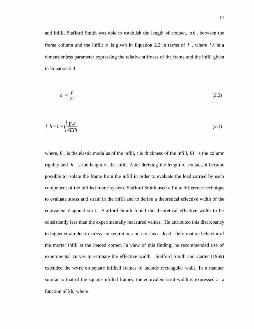
17
and infill, Stafford Smith was able to establish the length of contact, αh , between the
frame column and the infill; α is given in Equation 2.2 in terms of λ , where λh is a
dimensionless parameter expressing the relative stiffness of the frame and the infill given
in Equation 2.3
απλ
=2
(2.2)
4m
4EIhtEh =h ×λ (2.3)
where, Em is the elastic modulus of the infill, t is thickness of the infill, EI is the column
rigidity and h is the height of the infill. After deriving the length of contact, it became
possible to isolate the frame from the infill in order to evaluate the load carried by each
component of the infilled frame system. Stafford Smith used a finite difference technique
to evaluate stress and strain in the infill and to derive a theoretical effective width of the
equivalent diagonal strut. Stafford Smith found the theoretical effective width to be
consistently less than the experimentally measured values. He attributed this discrepancy
to higher strain due to stress concentration and non- linear load - deformation behavior of
the mortar infill at the loaded corner. In view of this finding, he recommended use of
experimental curves to estimate the effective width. Stafford Smith and Carter (1969)
extended the work on square infilled frames to include rectangular walls. In a manner
similar to that of the square infilled frames, the equivalent strut width is expressed as a
function of λh, where

18
4m 2
4EIhtEh =h θλ sin× (2.4)
In the above equation, θ is the angle of inclination of the diagonal to the
horizontal. They concluded that the lateral stiffness of an infilled frame may be obtained
by statically analyzing the equivalent pin-jointed frame in which the infill is replaced by
an equivalent diagonal strut. They also found that the effective width of an infill acting as
a diagonal strut was influenced by many factors. Some of the most influencing factors
were the relative stiffness of the infill and the frame, the wall’s aspect ratio, the stress
strain relationship of the infill material and the magnitude of the diagonal load on the
infill.
Provided that the frame members possess adequate strength, the authors suggested
that an infill consisting of concrete or mortar may fail by either tension cracking along
the loaded diagonal and/or crushing of the infill at the loaded corners. In addition to the
above modes of failure, a masonry infill may also fail by a third mode, namely, the shear
cracking along the interface between brick and mortar. They also concluded that column
stiffness can influence the stiffness and strength of the infill rather than the beam
stiffness, which have been shown to have little effect, and that whatever the beam
stiffness is, the length of beam in contact is always roughly half the span. Experimental
results also showed that the bending moments in an infilled frame relative to the same
non-filled frame subjected to similar forces are greatly reduced. They suggested design
charts corresponding to the mentioned three failure modes, from these charts, the failure
load in the equivalent diagonal strut can be obtained. Riddington and Stafford Smith

19
(1977) conducted an extensive series of plane stress finite element analyses of laterally
loaded infilled frames. The interaction between the frame and the infill was modeled by
introducing a linking matrix, representing the contact interface, connecting each two
adjacent nodes in the frame and the infill wall. This forced the nodes on the frame and
infill to undergo the same displacement if they are in contact. When sliding occurs
between the two nodes due to the presence of tension force in the interface, the linking
matrix forced the two nodes to have the equa l displacement only perpendicular to the
interface. They gave emperical equations based on the conducted stress analyses in order
to estimate shear stress, diagonal tension and vertical compression at the center of the
wall.
Mallick and Severn (1967) introduced an iterative technique whereby the points
of separation between the frame and the infill, as well as the stress distribution along the
length of contact between the frame and the infill, were obtained as an integral part of the
solution. Slip between the frame and the infill was also taken into account. Standard
beam elements were used to model the frame while plane stress rectangular elements
were used for the infill. The contact problem was solved by initially assuming that the
infill and frame nodes have the same displacement. Having determined the nodal
displacement, the load along the periphery of the infill is determined and checked for
tension. If a tension force is found, separation is assumed to have occurred and the
corresponding nodes on the frame and infill are allowed to move independently in the
next iteration. This procedure is repeated until a pre-described tolerance for convergence
is achieved. The effect of slip and interface friction was considered by introducing shear
forces along the length of contact. The authors ignored the axial deformations of the
20
columns in their formulation. Barua and Mallick (1977) used FE to analyze infilled
frames and their technique was similar to the method proposed by Sachanski (1960)
except that a finite element technique was used to determine stiffness coefficients of the
boundary nodes of the infill. Unlike Sachanski; Barau and Mallick allowed for the
separation between the infill and frame and included the effect of slip.
Mainstone (1971) presented results of series of tests on model frames with infills
of micro-concrete and model brickwork along with a less number of full-scale tests. He
found that factors such as the initial lack of fit between the infill and the frame and
variation in the elastic properties and strength of the infill can result in a wide variation in
behavior even between nominally identical specimens. Mainstone also adopted the
concept of replacing the infill with an equivalent pin-jointed diagonal strut; although he
believed the concept can only be justified for behavior prior to first cracking of the infill.
He plotted the aforementioned test results against the stiffness parameter, λh, and
empirically formulated three equivalent diagonal strut widths to evaluate the stiffness,
first crack load, and ultimate composite strength of the infilled frame.
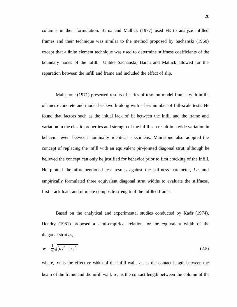
Based on the analytical and experimental studies conducted by Kadir (1974),
Hendry (1981) proposed a semi-empirical relation for the equivalent width of the
diagonal strut as,
( )w l h= +12
2 2α α (2.5)
where, w is the effective width of the infill wall, α l is the contact length between the
beam of the frame and the infill wall, αh is the contact length between the column of the
21
frame and the infill wall The above equation assumes that the contact stress has a
triangular distribution, and idealizes it into a uniform distribution of half the maximum
value of the triangular one. The contact lengths were obtained using Stafford Smith
method after modifying Equation 2.4 to suit the beam also and using Equation 2.2 to
obtain the column as well as the beam contact lengths.
Liauw and Kwan (1983) developed a plastic theory of non- integral (without shear
connectors) infilled frames in which the stress redistribution towards collapse was taken
into account and the friction is neglected for strength reserve. The theory was based on
the findings from non- linear finite element analysis and experimental investigation. The
results from the theory have been shown to compare favorably with the experimental
results given by many researchers on small-scale model tests. Series of equations
defining the ultimate load capacity as governed by various modes of failure was
suggested by Liauw and Kwan. The parameters involved in these equations were the
beam and column strength, the aspect ratio of the wall as well as its mechanical
properties. Liauw and Lo (1988) conducted a series of tests on a number of small scale
models of micro concrete infilled steel frames. The frame members were hot-rolled mild
steel solid rectangular bars. FE analysis was used to model the test specimens, taking into
account the no- linearity of material, cracking in the wall and separation-friction-slip at
the interface between the wall and the frame. In order to simulate the frame-wall
interface, each pair of adjacent nodes in the frame and wall elements were connected by
an interface element.

22
Dawe and Charalambous (1983) presented a finite element technique where
standard beam and membrane elements were used to model the frame and the infill wall,
respectively. Static condensation was then used to eliminate the interior degrees of
freedom of the infill leaving only the degrees of freedom associated with nodes adjacent
to the frame nodes. The interface between the frame and the infill was modeled with rigid
links and an iterative solution technique was adopted. At the end of each iteration, these
rigid links were checked, and for a link in tension, a static condensation technique was
used to eliminate the stiffness of this link.
The test program conducted in the early 1980s at the University of New
Brunswick was one of the most intensive experimental programs conducted on a
monotonically loaded full scale steel frames infilled with concrete block masonry. The
tests were conducted by McBride (1984), Yong (1984), Amos (1986), and Richardson
(1986). Of the parameters investigated by these studies, the interface conditions between
the wall edges and frame were found to significantly affect the strength and behavior of
the system. Column-to-wall ties were found to be ineffective in increasing ultimate
strength while initial stiffness was only marginally increased. A small gap between the
upper edge of the wall and the roof beam was particularly detrimental to the system in-
plane shear capacity. Tests of specimens with wall openings have shown that, while
openings may reduce initial stiffness and first crack load, the same was not necessarily
true for their effects on ultimate strength. Placing reinforced bond beams at one-third and
two-thirds the wall heights was found to bring the major crack load close to the ultimate,
which itself was only marginally increased. Strengthening the compression diagonals by

23
grouting vertical reinforcing bars of lengths equal to the expected compression diagonal
width into the cells of the concrete block wall resulted in only minor increases in stiffness
and ultimate strength. A summary of the above studies was presented by Dawe and Seah
(1989).
Seah (1998) suggested an analytical technique, in which the steel frame was
modeled using elastic beam-column elements connected with nonlinear rotational, shear,
and normal springs. The masonry wall was represented by a series of elastic plane stress
elements connected together by a series of springs representing the mortar joints as
shown in Fig. 2.2. The suggested analytical technique gave very good results up to failure
as shown in Fig. 2.3, when it was used to model the specimens of the aforementioned
testing program conducted in the University of New Brunswick. The model was
sophisticated enough to account for the variation in contact lengths and the failure of
mortar joints due to shear, tension or compression.
Paulay and Priestley (1992) suggested treating the infill walls as diagonal bracing
members connected by pins to the frame members. They also suggested to calculate the
stiffness of the structure and hence its natural period based on considering the effective
strut width to be one quarter the wall diagonal.
Saneinejad and Hobbs (1995) proposed a method of analyzing masonry infilled
steel frames subjected to in-plane loading. The method utilized the data generated from
previous experiments as well as the results of a series of non-linear FE analyses. The
24
proposed method accounts for both the elastic and the plastic behavior of infilled frames
and predicts the strength and stiffness of the infilled frames. The method also accounted
for various parameters like different wall aspect ratios and different beam-to-column
stiffness and strength. The method was based on using equilibrium and elasticity
equations to generate various parameters governing the behavior of the infilled frame
system like the contact stresses and lengths along with the initial stiffness of the infilled
frame as well as the secant stiffness at failure. The authors also assumed that at failure,
full plastification occurs at the loaded corners of the frame as well as the part of the infill
in-contact with the frame. The authors suggested that the resistance to lateral loads was
offered by three components. These components are: the force induced due to shear
stresses on the beam-wall interface, the force generated by the normal stresses on the
column-wall interface and finally the force developed in the steel frame itself as a result
of its own stiffness to horizontal loads. Having derived the ultimate load, the area of the
diagonal strut was easily derived. The collapse load and the initial stiffness as predicted
by the proposed method was compared to tests conducted by others and was found to
give satisfactory results. Further discussion of Saneinejad and Hobbs’s work will be
presented in Chapter Five.
Madan et al. (1997) further extended the work of Saneinejad and Hobbs (1995) by
including a smooth hysteretic model for the equivalent diagonal strut. The hysteresis
model uses degrading control parameters for stiffness and strength degradation and slip
(pinching).

25
Mosalam et al. (1997-a,b,c) reported the results of a series of tests on single-bay
single-story and two-bay single-story concrete blocks masonry infilled steel frames tested
under quasi-static loading and two-bay two-story frames tested under pseudo-dynamic
loading. All the specimens were one-forth scale gravity loads designed frames with a
semi-rigid connection between the frame members. Along with the variations in the
number of bays and/ or stories, the relative strength of the concrete block and mortar and
the effect of openings were also considered. The authors also suggested three analytical
models to model the masonry wall. The first model was a microscopic level model in
which each block was modeled separately and the mortar joints were modeled using
interface elements. In the second model, referred to as a meso model, the wall as whole
was modeled as an orthotropic plate. The third model was a macroscopic level model in
which the wall was represented by a truss with nonlinear truss members. In both the meso
and the macro models; unlike the micro model, the properties of each model were chosen
to match the experimental findings.
Flanagan et al. (1999) reported the results of a number of full scale clay infilled
steel frames tested under in-plane loading. A piecewise linear equivalent diagonal strut
was used to model the infill. The behavior of the structural clay tile infills was correlated
with the absolute story drift rather than the nondimensional story drift. The area of the
strut, A, was given by Equation 2.6
θλπcosCtA = (2.6)

26
where, t, λ and θ are defined in Equation 2.4 and C is an empirical constant depending
on the in-plane drift displacement.
Manos et al. (2000) experimentally investigated the influence of masonry infills
on the earthquake response of multi-story RC frames. Small scale 2-D and 3-D structures
were tested with and without infill under base motion simulating an earthquake
excitation. During the test the masonry infill of the first story developed clear signs of
distress in the form of horizontal cracking. The masonry was then demolished and
replaced by a new masonry wall, again the replaced wall suffered damage, this time in
the form of diagonal cracking. A large increase in the fundamental frequency was
observed after the addition of the infill, yet this increase was not constant since a rapid
decrease in the stiffness of the infill occurred due to its damage. This displays a
significant aspect in the behavior of weak masonry infills ; for moderate earthquake
loads they may retain their stiffness and thus participate up to a degree in the load bearing
capacity; however, due to their brittle behavior this participation soon ceases to exist after
they are damaged.
Kappos et al. (2000) conducted an analytical study on the seismic performance of
masonry infilled RC framed structures. It was found that taking the infill into account in
the analysis resulted in an increase in stiffness as much as 440%. It is clear that,
conditional upon the spectral characteristics of the design earthquake, the dynamic
behavior of the two systems (bare vs. infilled frame) can be dramatically different.

27
They also presented a very useful global picture of the seismic performance of the studied
infill frames by referring to the energy dissipated by each component of the structural
system, shown in Figure: 2.4 as a function of the earthquake intensity considered. It is
clear that at the serviceability level over 95% of the energy dissipation is taking place in
the infill walls (subsequent to their cracking), whereas at higher levels the RC members
start making a significant contribution. This is a clear verification of the remark that
masonry infill walls act as a first line of defense in a structure subjected to earthquake
attack, while the RC frame system is crucial for the performance of the structure to
stronger excitations (beyond the design earthquake).
El-Dakhakhni (2000), El-Dakhakhni et al. (2001) suggested a modeling technique
for concrete masonry infilled steel frames, as shown in Fig. 2.5. The technique is based
on replacing the infill wall by one diagonal and two off-diagonal struts. It is based on
making use of the orthotropic behavior of the masonry wall as well as some experimental
observation, and analytical simplifications, in order to simplify the nonlinear modeling of
these structures.
2.3 THE USE OF MASONRY INFILL WALLS AS A RETROFITTING TECHNIQUE
Having realized the unaccounted-for effect of the masonry walls in strengthening
as well as stiffening existing framed structures, many researchers, Durrani et al. (1992),
Islam et al. (1994), Pincheira et al. (1995) used the masonry infills themselves as a mean
of retrofitting or strengthening existing framed buildings. The inclusion of the infill, as
expected, was found also to be an effective way to reduce lateral drift. In some countries

28
(Mexico), there is an evidence that masonry infill walls improved the performance of
existing moment-resisting frames structures under severe earthquake loads (Amrhein et
al. 1985). Observations of the structural damage that occurred during the 1992 Cairo
earthquake, Adham (1994), lead to the conclusion that in moderate seismic areas, the
presence of the masonry infill enhances the shear resistance of buildings as well as
increasing the stiffness of the flexible framed buildings found on soft soils.
In 1997 the Federal Emergency Management Agency (FEMA) published the
FEMA-273 document providing a set of nationally applicable guidelines for the seismic
rehabilitation of existing buildings. In this document, and in order to include the
beneficial effect of the infills in the analysis of rehabilitated buildings, the elastic in-plane
stiffness of a solid URM infill walls prior to cracking shall be represented with an
equivalent diagonal compression strut of width, a, given by Equation 2.7. The equivalent
strut shall have the same thickness and modulus of elasticity as the infill wall it
represents.
a = 0.175(λ1 hcol)-0.4 rinf (2.7)
where, hcol is the column height between centerlines of beams in inches, rinf is the
diagonal length of infill wall in inches and λ1 is the same as λ defined earlier in Equation
2.4.
Decanini et al (1994) conducted an analytical study to investigate the effect of
adding infill walls on reinforced concrete framed buildings. They concluded that the
proper design of the infill should result in decreasing the bending moments in both the

29
columns and the beams of the framed building. In fact, the addition of the infill
distributes the moments more uniformly. It is also worth mentioning that the axial force
level in the leeward columns increase and this increase should be accounted for during
the design process. They also concluded that the addition of the infill causes significant
changes in the dynamic characteristics of buildings and their behavior during
earthquakes. The inclusion of the infills increases the capacity of the structure to dissipate
energy due to cracking of the infill, friction between the infill and the surrounding frame.
Although the Infills generally increase the base shear calculated using the equivalent
static load method due to the decrease in the natural period resulting from the stiffness
increase, yet, if properly designed, the increase in the strength supplied by the infills
exceeds considerably the increase in strength demand. Another beneficial effect of the
infills is their dramatic role in reducing the inter-story drift and the overall lateral
displacement of the building, limiting, in this way, the damage of both structural as well
as non-structural elements.
Murty et al. (2000) presented an experimental study on masonry infilled RC
frames showing the beneficial effect of the masonry infill in energy dissipation and
overall ductility capacity of the building system. They found that, due to infilling, the
stiffness increases more than four times, the strength increases by 70%, the ductility
increased four times. They also concluded that the inclusion of masonry infill drastically
reduces the ductility demand on the RC frame members. This explained the excellent
performance of many such buildings in moderate earthquakes even when the building is
not designed or detailed to withstand the earthquake forces.

30
2.4 RETROFITTING TECHNIQUES FOR MASONRY STRUCTURES
Several retrofitting techniques are available to increase the strength and the
ductility of masonry buildings. These can be categorized in two types, the first relates to
adding structural elements such as steel or concrete frames to the existing building. This
option presents some disadvantage such as adding significant weight to the building,
which in turn may require foundation adjustments, resulting in a higher retrofit costs as
well as resulting in higher inertia forces in the event of an earthquake. Another
disadvantage is that valuable space is lost to the framing elements, and in some cases
disturbance of the occupants may occur. The second alternative is related to surface
treatment. This alternative can be achieved in many ways. A standard procedure consists
of removing one wythe from the existing multi-wythe wall and replacing it by a layer of
reinforced concrete. In some cases, the walls are retrofitted with steel plates attached to
the wall with steel anchors. Another way is to simply apply an external coating or
overlay to one or both sides of the masonry wall. This includes the use of sprayed
concrete, glass-reinforced concrete coating, steel fiber reinforced concrete coating or
ferrocement coating [Prawel and Reinhorn (1985)].
In a study conducted in the University of California-Berkeley by Tso et al. (1974)
Cagley et al. (1978), Clough et al. (1979), and Meli et al. (1980), masonry walls coated
with either reinforced plaster or fiberglass reinforced mortar were tested under in-plane
cyclic loading or under simulated earthquake loading, the strength of the walls were
nearly doubled and the coating increased the ductility of the system.
Hutchinson et al. (1984) conducted a research on the different methods used to

31
reinforce URM walls subjected to in-plane cyclic loading, they used variety of techniques
such as longitudinal prestressing, shotcrete on one surface, glass-reinforced cement on
both surfaces, a combination of dowels, and steel- fiber reinforced coating on two
surfaces, and the addition of a the ferrocement to one side of the wall. They came out
with the conclusion that among all the methods considered, the solution involving
spraying the concrete, and in particular the use of steel- fiber reinforced coating, were
determined to be the most viable retrofitting method. This technique resulted in
remarkably stable hysteresis loops.
Reinhorn et al. (1985) conducted a study on diagonal tension specimens with and
without ferrocement retrofitting. The ferocement doubled the ultimate strength of the bare
specimens and increased their ductility.
Weeks et al. (1994) reported one of the largest test programs conducted to date in
the field of full scale testing of masonry structures at the University of California – San
Diego. A full-scale five-story reinforced concrete masonry building was tested under
simulated seismic loading. The damaged building was repaired subsequent to the original
seismic test with carbon fabric overlay on the first two stories, ceramic foam injection of
damaged hollow core floor blanks, and reconstruction of crushed wall toes in the first
story wall with polymer concrete. The repaired building was retested using the same
loading history applied to the original building. A direct comparison with the first test
results showed that the repair improved the seismic deformation capacity by a factor of
two and that particularly the polymer matrix based carbon fabric wall overlays proved to
be highly effective in reducing shear deformations in the structural walls and in

32
improving the overall structural ductility.
Mander and Nair (1994) tested medium scale clay masonry infilled steel frame
sub-assemblages with and without retrofitting under in-plane quasi-static cyclic loading.
The retrofitting scheme involved the use of ferrocement overlays with and without
diagonal reinforcing bars. They concluded that the URM infills can act as a ductile lateral
load resisting element in multi-story frames. Including the ferrocement overlay increased
the ductility even more, and the enhancement of the ferrocement using the diagonal
reinforcing bars resulted also in increasing the strength as well as the energy dissipation
capabilities of the system. The diagonal bars also helped in preventing the out-of-plane
buckling of the ferrocement layer. They suggested that such rehabilitation technique
could be used in the lower story of multi-story frames where most of the plastic hinging
would normally occur under earthquake loading.
Laursen et al. (1995) tested URM shear walls with and without CFRP retrofitting
both under in-plane and out-of-plane loading. The carbon fibers doubled the ductility of
the wall and increased its carrying capacity by 25%.
Ehsani et al. (1997) investigated the shear behavior of URM shear specimens
retrofitted with FRP overlays as shown in Fig. 2.6. Two modes of failure were observed
namely, the shear failure mode along the joint and, the delamination of the fabric at the
middle-brick region or fabric edges. They concluded that the type of failure was
influenced by the fabric strength, whereas the shear failure was associated with the
weaker fabric, and the delamination occurred when a stronger fabric was used.
Ehsani (1998) reported that composite materials are very effective in

33
strengthening URM structures, where the tensile and shear capacity of the wall is
negligible. Fabric of the composite material can be epoxy bonded to the exterior surface
of the wall, similar to wallpaper. The fabrics can be easily cut to accommodate any
opening. For an infill wall, even a thin fabric may be sufficient to contain the wall and
prevent its collapse. The composite forces the whole wall to work integrally and increase
the shear strength as well as the flexural out-of-plane strength and convert the URM into
a ductile material. Ehsani et al. (1999) studied the behavior of half-scale URM walls
retrofitted with vertical FRP strips subjected to simulated earthquake out-of-plane
loading. They concluded that although both URM walls and the FRP strips behave
separately in a brittle manner, the combination resulted in a system capable of dissipating
energy.
Traitafillou (1998) conducted a study to experimentally as well as analytically
investigate the effect of strengthening masonry structures for out-of-plane bending, in-
plane bending, and in-plane shear capacity all combined with axial loading. He came up
with design equation and normalized interaction diagrams for the different loading cases.
It was shown that the inclusion of the laminates increased the shear capacity three to five
folds.
Kolsch (1998) presented a method for out-of-plane strengthening of masonry
infills using carbon fiber embedded in a cement-based matrix. The technique prevented
partial or complete out-of-plane collapse of the wall. The ultimate strength of the wall
increased to 300% of that expected for the un-strengthened wall and the deformation
capacity was also greatly enhanced.

34
Taghdi et al. (2000) suggested a method to increase the in-plane strength and
ductility of masonry shear walls founded in low-rise buildings. In their testing they
retrofitted the walls using vertical as well as vertical and diagonal steel strips. Steel
angles and anchor bolts were used to connect the steel strips to the foundation and the top
loading beam. In essence, as shown in Fig. 2.7 the walls were transformed into a masonry
infilled frame with or without diagonal steel braces. The walls were subjected to both
gravity as well as cyclic in-plane loadings. It was noticed that the retrofitting scheme
increased both the ultimate strength as well as the ductility of the wall many folds. It was
also concluded that while the above upgrading technique is effective, it requires a great
deal of preparation work, its construction may disturb the ongoing building functions, and
the new structural elements may affect the architectural aesthetics of the building. Hence,
an alternative retrofitting technique is worth considering.
Very little research has been conducted in the area of retrofitting masonry infilled
frames using GFRP laminates to enhance its in-plane behavior. To the author’s best
knowledge, the first research conducted in this field was that by Haroun et al. (1996). In
this study, full scale hollow concrete block masonry infilled RC frames with and without
FRP retrofitting were tested under cyclic in-plane loading. It was noted that the fiber
composite increased the ultimate strength of the original frame by 35%, but more
important, the ductility of the retrofitted frame was 280% more than the original infilled
frame.
Colombo et al. (2000) conducted an experimental study on the effect of using a
polymeric net embedded in plaster coating on improving the ductility and energy-
dissipation capability of masonry infilled steel frames. This technique is very close to the
35
FRP application and it was found to be very effective in increasing the energy dissipation
capacity.
Hakam (2000) conducted a preliminary study at Drexel University on GFRP
retrofitted small-scale masonry infilled steel frames tested under diagonal monotonic
loading. Figure 2.8 schematically shows the effect of the GFRP on the stiffness and the
ultimate strength of the retrofitted infilled frames.
2.5 SUMMARY AND CONCLUSIONS
This chapter summarizes the experimental and theoretical research work
conducted in the area of infilled frames. It is now widely recognized that masonry infill
walls used for cladding and/or partition in buildings, significantly alter their seismic
response, and their effect in changing the stiffness, the ultimate lateral load capacity as
well as the ductility supply of the building system should be accounted for in analysis and
design.
Due to the complexity of the contact problem, the sophisticated composite action
of the frame and the infill, and the incomplete understanding of the infill role, as well as
the numerous uncertainties involved in modeling the effect of infills; design aids such as
manuals and software as well as related code provisions hardly include any detailed
guidance to take into account the effect of the infills. On the other hand, attention is
usually given to the contribution of the infills in the case of structural evaluation or
retrofitting, where the overlooked infills are considered to be of most importance and
actually the first line of defense.

36
A simplified analysis, derived from the material properties as well as design
guidelines to account for different parameters is thought to be the best way to include the
infill walls into the design of multi-story framed structures. The beneficial effect of using
FRP laminates in retrofitting masonry and concrete structural element is clearly
established in the literature. Significant change in the dynamic behavior of such
retrofitted structure is clear. In view of the growing demand to retrofit existing masonry
and concrete structures or to facilitate the inclusion of the infills in the analysis and
design of new structures, there is an urgent need to establish a modeling technique for
FRP retrofitted masonry infilled steel frames.
The objective of this research work is to investigate the feasibility and impact of
bonding GFRP laminates to URM infill walls confined in structural steel frames as a
seismic retrofitting scheme in order to improve the seismic performance of these widely
used building systems.

37
Fig. 2.1: The Diagonal Compression Strut
Fig. 2.2: The Infilled Frame Model Proposed by Seah (1998)

38
Fig. 2.3: Load-Deflection Behavior of a Specimen Modeled by Seah (1998)
Fig. 2.4: Energy Dissipation in Each Component of the Infilled Frames Structure
Investigated by Kappos et al. (2000)
Deflection (mm)0 50 100 150 200 250
0 50 100 150 200 250
Load
(kN
)
0
100
200
300
400
500
600
Experimental - Specimen WD7 (Richardson 1986)AnalyticalFrame with no infill

39
Figure 2.5: The Infilled Frame Model Proposed by El-Dakhakhni (2000)
Fig. 2.6: The FRP Retrofitted Shear Specimen investigated by Ehsani et al. (1997)
beam-column joint
h
columnθ
l
bα
hcα
l A/4=A
A
1
A/22=
beamA/4=1A
Load
FRP overlay

40
Fig. 2.7: The Steel Strips Retrofiting Technique Suggested by Taghdi et al. (2000) for URM Walls
Fig. 2.8: The GFRP Effect on The Diagonally Loaded Masonry Infilled Steel Frames
Tested by Hakam (2000) [reproduced]
(105 kN @ 11 mm)
Bare frame∆ Pu-I
(95 kN @ 1.6 mm)P∆ u-R
in-B
Deflection
(28 kN @ 12 mm)
Infilled frame
K
(220 kN @ 6 mm)
Retrofitted framein-IKin-RK
Load
P

41
CHAPTER 3: TESTING OF WALL SUBASSEMBLAGES RETROFITTED WITH GFRP LAMINATES
3.1 INTRODUCTION
The experimental investigation conducted and documented in this chapter studies
the in-plane behavior of face shell mortar bedding (FSMB) unreinforced masonry
(URM) wall subassemblages strengthened with different glass fiber-reinforced polymer
(GFRP) composite laminates. A total of fifty-seven assemblages of URM were tested
under different loading conditions. Twenty-four specimens were loaded in compression
normal to the bed joints, Nine were compressed parallel to the bed joints, and twenty-four
specimens were loaded under direct shear. Parameters such as the fiber types, the number
of plies, and the fibers orientation were investigated. The general behavior of each
specimen type is discussed with emphasis on failure loads, and modes of failure. The use
of GFRP laminates for in-plane strengthening of masonry walls produces an engineered
masonry-GFRP composite wall in which the masonry face shells provide the compressive
strength and the GFRP laminate supplies the required tensile and shear strengths as well
as assisting the face shells in carrying compression loads.
One of the objectives of the presented experimental work is to investigate the
effects of different GFRP laminates on the strength, failure modes as well as the post
peak strength of subassemblages compressed in the two orthogonal directions. Another
objective is to demonstrate that, with the proper selection of the GFRP laminate, shear
failure, which is a common failure mode in URM, can be eliminated. This rather brittle
42
failure mode is usually attributed to the low shear strength of URM or to the inadequate
shear reinforcement in reinforced walls.
3.2 EXPERIMENTAL PROGRAM
The experimental program consisted of three different types of subassemblages:
namely; prisms loaded normal and parallel to the bed joints, and direct shear specimens.
The test specimens were chosen to represent typical loading cases of masonry walls in the
two orthogonal directions as well as shear loading along the weak mortar bed joints as
shown in Fig. 3.1-a. A total of 57 full-scale specimens were constructed in the laboratory
and tested to failure under monotonically increasing loads. Out of these specimens, 24
were loaded normal to the bed joints, 9 were loaded parallel to the bed joints, and 24
were loaded under direct shear. The specimens were loaded in a displacement controlled
scheme, at a rate of 0.011 mm/s (0.025 in./min), and the displacement was measured
using two Linear Variable Differential Transducers (LVDTs) mounted to the center of the
loading plates on each side of the specimen. The LVDTs were connected to a data
acquisition system recording also the applied load on the specimens.
Nominal [400 3200 3150 mm (16 38 36 in.)] standard hollow concrete masonry
blocks certified to meet the provisions of ASTM C-90 standard and Type S mortar
(ASTM C-270) were used in the construction of the subassemblages. Three different
glass fiber fabrics were used, namely, Tyfod WEB, Tyfod BC, and Tyfod SEH-51A
all with the same Tyfod S epoxy matrix, the fabrics and the epoxy were all supplied by
Fyfe Co. LLC of Del Mar, California. The properties of the GFRP composites were
supplied by the manufacturer and are given in Table 3.1.
43
Each strengthened specimen was assigned a name according to the notation shown in the
example of Fig. 3.2. The name was chosen to represent the parameters investigated in
this study, namely, the type of loading, the fibers type, the fibers orientation, and the
number of plies. For example, CP-S-B would refer to a specimen loaded in Compression
Parallel to the bed joint, strengthened with Tyfod SEH-51A laminate applied Bi-
directionally.
3.3 PREPARATION OF TEST SPECIMENS
In order to minimize the statistical variability in the blocks strength, all the blocks
used in this study were from the same batch. The blocks had an average compressive
strength of 21.4 MPa (3,100 psi) and 19.3 MPa (2,800 psi) based on the net areas of the
blocks when tested flatwise and endwise, respectively. Selection of blocks was conducted
according to the ASTM C-140 requirements. In order to minimize the workmanship
effect on altering the assemblages properties, all specimens were constructed by the same
experienced mason. All specimens were constructed with Face Shell Mortar Bedding
(FSMB). The CN specimens were laid in a stack bond pattern, whereas both the CP and
DS specimens were laid in a running bond. Four batches of Type S mortar were mixed
during the two-day assemblages construction. Three [50350350 mm (23232 in.)] mortar
specimens were taken from each mortar mix and tested for compressive strength as per
the ASTM C-109. The average mortar strength was found to be 20.7 MPa (3,000 psi).
The mason was allowed to dictate the amount of water in the mortar mix and retemper it
as required. The mortar joints were tooled to produce a concave profile. The tooling
produces a denser compacted surface and forces the mortar into tight contact with the

44
masonry units. All specimens were allowed to cure for at least 28 days before fiber
reinforcement was applied.
Before applying the GFRP, the specimens surfaces were first cleaned from dust
and mortar protrusions using a wire brush. The epoxy mixture was then liberally applied
using a hand held paint roller to the specimen surfaces. The dry fabrics were then placed
on the wet surfaces and more epoxy was applied to insure complete saturation. Any
excess epoxy was then removed by running the roller several times on the wet fabrics.
This also ensures that minimum air voids are trapped. All the strengthened specimens
were left at least five days to cure before testing. This was more than the three days
epoxy curing time, suggested by the manufacturer. The top and bottom of the
compression prisms and the shear specimens were capped with a thin layer, [1-2 mm
(0.04-0.08 in.)], of Hydrostone to insure full contact with the loading plates.
3.4 TEST RESULTS AND DISCUSSION
The results of the subassemblages tests are presented in the following two
sections. The first section presents and discusses the stress-strain behavior, the observed
failure modes of the compression prism specimens, loaded in both directions, normal and
parallel to the bed joints. The second section presents the observed modes of failure of
the direct shear specimens.
3.4.1 SPECIMENS BEHAVIOR UNDER AXIAL COMPRESSION
3.4.1.1 STRESS-STRAIN BEHAVIOR
This experimental investigation included twenty-four [40034003150 mm
(1631636 in.)] FSMB prism loaded in compression normal to the bed joints and nine

45
[40038003150 mm (1633236 in.)] FSMB prism loaded in compression parallel to the bed
joints. The test specimens are shown in Fig. 3.1-b and Fig. 3.1-c, for the CN and the CP
specimens, respectively. The test matrix and results are shown in Table 3.2.
Figure 3.3 shows typical stress-strain relations for the CN-Bare, CN-W-1, CN-
W-2, and CN-S-P specimens; whereas Fig. 3.4 shows the same relations for specimens
CN-B-1, CN-S-N, and CN-S-B along with the CN-Bare specimen for comparison. It can
be noted from these figures that for the strengthened CN specimens, the compressive
strength capacity increased by as low as 20% for the CN-S-P to as high as 75% for the
CN-S-B specimens. This ratio increased to 90% for specimens CP-S-B when compared
to the CP-Bare specimens as seen in Table 3.2. There was a slight increase (10%) in the
initial stiffness for most of the strengthened specimens.
3.4.1.2 FAILURE MODES OF THE BARE SPECIMENS
The failure mode of all the unstrengthened prisms was initiated by vertical web
cracking, usually at approximately 85% and 90% of the ultimate load for the CN-Bare,
and the CP-Bare, respectively. The web splitting of the CN-Bare specimens, shown in
Fig. 3.5-a is attributed to both the deep beam action associated with FSMB as well as the
different material characteristics of the mortar and the blocks. This behavior was
explained by Drysdale et al. (1999). The mortar tends to expand laterally under
compression at a greater rate than the masonry blocks. However, the block restrains the
mortar expansion, thus, the mortar is under a state of triaxial compression whereas tensile
stresses are initiated in the blocks on both sides of the bed joint in order to maintain
equilibrium. Consequently, non-uniform stresses occur along the height of the unit where
46
the principal tensile stresses occur near the top and bottom of the web while the central
region of the block is under compression. This tension-compression state of stress in the
block ultimately results in vertical web splitting. For the CN-Bare prisms, the splitting
cracks left the two face shells to deform individually, as shown in Fig. 3.5-b, with a high
slenderness ratio. Finally, the specimens totally disintegrated as a result of the out-of-
plane buckling and/or spalling of the face shells or a combination of both, as shown in
Fig. 3.6.
For the CP-Bare specimens, cracking of the two face shells preceded the vertical
web splitting. The cracking of the CP-Bare face shells was of two patterns. The first type,
which appeared at approximately 65% of the ultimate load, was in the form of vertical
separation cracks along the bed joints due to the differential normal deformation in block
and adjacent joints as well as the low adhesion strength between the mortar and the
blocks. The second type of cracks were inclined in-plane shear-compression cracks. Both
crack types are shown in Fig. 3.7-a. As soon as the vertical web splitting occurred, cracks
due to the out-of-plane bending of the face shells developed. These cracks, which are
attributed to the out-of-plane bending and the frame action developed when loading
parallel to bed joints, started at the outer side of the face shells, and developed
immediately before, and lead to, ultimate failure.
3.4.1.3 FAILURE MODES OF THE STRENGTHENED SPECIMENS
For the GFRP strengthened specimens, the web splitting occurred under a load
approximately equals the ultimate load capacity of the bare specimens. Three failure
modes were observed when testing the strengthened CN and CP specimens depending on
47
the type of the laminate. The first mode was associated with the weak laminates used in
specimens CN-W-1, CN-W-2 and CN-S-P. In this mode, failure occurred by tearing of
the laminate as shown in Figs. 3.8-a and 3.8-b for specimens CN-W-2 and CN-S-P,
respectively. This is attributed to the fact that after web splitting, as shown in Fig. 3.8-c,
the two face shells act individually as separate walls under compression load and bending
resulting from out-of-plane buckling. As the face shells tend to buckle as in the case of
the bare prism, the laminates provide the tensile strength to prevent the disintegration of
the specimen. The more the load applied the more the eccentricity and hence the more
tension applied on the laminates till the laminates fail.
The second failure mode occurred with specimens CN-S-N, CN-B-1 and CP-B-1.
The laminate was not only stronger but more importantly stiffer, to the extend that it
maintained the straightness of the face shell and reduced the eccentricity. This effect
produced not only stronger composite prisms but also ones with apparent post peak
strength. This, resulted from the incremental separation of the webs off the face shells, as
shown in Fig. 3.7-b, and crushing of the face shells in the loaded ends under the
confining effect of the laminates. The post peak strength is also due to the gradual
delamination and out-of-plane buckling of the laminate itself. The end-crushing was
controlled by the laminate since it maintained the integrity of the face shell even after
crushing of the loaded part of the face shell. This was followed by more crushing, till
finally the face shell began to separate in the form of a wedge at the two loaded ends as
shown in Figs. 3.9-a and 3.9-b.
The third failure mode was associated with specimens CN-S-B and CP-S-B. The
laminates were the strongest and the stiffest laminates used in this experimental program.

48
The failure was initiated, as expected, by web splitting followed by a gradual increase in
the load till the specimens reached an average load of 175% and 190% of the ultimate
load for the CN-Bare and the CP-Bare specimens, respectively. After reaching the peak
load, a sudden bang was heard as a result of webs completely braking off the face shells,
and the loaded parts of the face shells split into wedges as described earlier. As a result,
the load suddenly dropped to approximately 80% of the bare prisms capacity. The
specimens continued to carry more load under a displacement controlled loading scheme
with a gradual decrease in capacity till finally the whole laminate or a major part of it
suddenly buckled out-of-plane as shown in Fig. 3.10. The laminate buckling diminished
the confinement of the face shells which then began to spall causing failure of the
specimen.
3.4.2 SPECIMENS BEHAVIOR UNDER DIRECT SHEAR
3.4.2.1 FAILURE MODES OF THE BARE SPECIMENS
The GFRP laminates effect on the shear strength of the weak mortar bed joint was
investigated using 24 FSMB specimens of the one shown in Fig. 3.1-d. The testing
program contained eight different sets of specimens for the DS specimens, each set
consisting of three identical specimens. The test matrix is shown in Table 3.3 as well as
the results, which are also graphed in Fig. 3.12. All specimens were constructed
horizontally as they would be in an actual wall using 10 mm (3/8 in.) spacers to provide
the space for the mortar joint as shown in Fig. 3.1-e. The head mortar joint between the
two middle blocks was left unfilled to allow for the specimen to fail in shear. This
arrangement was first suggested by Hamid (1978), in order to apply a pure shear on the
49
bed joints by eliminating the additional bending moment that occurs when using triplet
specimens. These shear stresses will create two diagonal tension fields as shown in Fig.
3.13-a. While this might be the case in the specimen under consideration, yet in actual
walls, diagonal tension fields in only one of the two directions will occur depending on
the direction of the lateral load. In fact, the presence of pre-compression stresses from
gravity loads will change the direction of the diagonal tension fields depending on the
principle stresses orientation.
The failure of the bare specimen was a brittle debonding mode at a very low load
and displacement levels. This is a result of the weak adhesion strength and the absence of
friction resistance due to the lack of compressive stresses normal to the mortar bed joints.
The failure was in the form of complete separation in the top and/or bottom mortar joints
(Fig. 3.13-b). On the contrary, the strengthened specimen fail at a much higher load with
a noticeable post peak strength.
3.4.2.2 FAILURE MODES OF THE STRENGTHENED SPECIMENS
The above mentioned state of stress resulted in one of four different failure modes
to occur depending on the laminate type. The first mode was associated with specimens
DS-W-1, DS-W-2, DS-W-3 and DS-S-P. The failure was in the form of laminates tearing
in the vicinity of the mortar joints. This mode is associated with weak strength laminates
relative to the bond strength between the GFRP and the masonry. The failure is initiated
by tearing of the laminates on either sides of the block A (see Figs. 3.13-a and 3.13-c),
followed by tearing of the laminates on the opposite side of the block D. Although this
mode is relatively brittle, yet, it is more ductile than the sudden failure associated with

50
the DS-Bare specimens. That is because, except for the unidirectional laminates used in
specimens DS-S-P, the laminates were not suddenly torn and it withstood lower load
levels after partial tearing. In fact, DS-W-1, DS-W-2, and DS-W-3 specimens were able
to withstand post peak loads of 63%, 71% and 69%, respectively. This behavior has been
also reported by Ehsani (1997) using different laminate lengths to retrofit brick triplet
shear specimens.
The second mode, associated with specimens DS-S-N, was a partial delamination
of the laminate in the vicinity of the mortar joints due to the fact that being unidirectional,
the laminates can withstand no shear deformation and it can only provide dowel action
as shown in Fig. 3.13-d. The third failure mode, associated with DS-B-1 specimens, was
a delamination of the laminates from the top block or in the form of a diagonal region
representing the diagonal tension field as shown in Fig. 3.13-e. It was apparent that as
soon as the delamination occurred between blocks A and B, blocks A and C, transfer the
force to block D now attached to block B. This explains both the tearing mode and the
diagonal delamination modes. Occurrence of this mode is associated with relatively
stronger laminates relative to the bond strength. This mode is considered the most ductile
mode, since the delamination proceeds more gradually than the laminate tearing. The
forth mode, associated with specimens DS-S-B, represents failure of the top and/or lower
block, with little or no delamination in the laminates. This mode, (Fig. 3.13-f), is
associated with strong laminates with good bond between the laminates and the blocks.
This mode simply means that with certain laminates the shear failure can be totally
eliminated and the strength will be governed by the compressive strength of the
composite prisms.

51
3.5 CONCLUSIONS
The following conclusions resulted from the study presented in this chapter:
1. By eliminating the shear failure using properly selected GFRP laminates, the long
known anisotropy of masonry resulting from the complex shear-compression interaction
along the weak mortar joints [Hamid and Drysdale (1980)] can now be eliminated. In this
engineered masonry-GFRP composite wall, the GFRP laminate can supply the required
shear strength, and the face shells will be provide the compression strength.
2. The GFRP laminates will also improve the compression strength of the face shells by
supplying the tensile strength required to stabilize the out-of-plane buckling of the
individual face shells, thus preventing the out-of-plane buckling failure.
3.The masonry-GFRP composite assemblages do not fail catastrophically as their URM
counterparts. The GFRP laminates resulted in a gradual prolonged failure under shear,
and a stronger wall under compression with apparent post peak strength.
4. The GFRP laminates maintain the wall integrity, contain and localize the damage of
the URM walls even after ultimate failure, as seen in Fig. 3.11. This keeps the face shells
of all the blocks as one plate, thus reducing the possibility of the external walls or
partitions spalling, which, in itself, a major source of hazard during earthquakes even if
the whole structure remains safe and functioning.
5. By supplying the shear strength at the mortar joints, the laminate eliminates the effects
of poor workmanship, initial cracks and defects, as well as mortar deterioration by
weathering, shrinkage and aging. Such factors that greatly alter the quality and strength
of the bond between blocks and mortar, which is the dominant factor in determining the
shear strength of URM.

52
Table 3.1: GFRP Composites Properties
Composite Property Tyfod WEB Tyfod BC Tyfod SEH-51A ASTM
method Ultimate tensile
strength in primary fibre direction MPa (psi) [kip/in
width]
309 (44,800) [0.45]
279 (40,500) [1.37]
575 (83,400) [4.17] D-3039
Elongation at break 1.6 % 1.5 % 2.2 % D-3039
Tensile Modulus GPa (psi) 19.3 (2.83106) 19.0 (2.73106) 26.1 (3.83106) D-3039
Ultimate tensile strength 90 degrees to
primary fibres MPa (psi) [kip/in
width]
309 (44,800) [0.45]
279 (40,500) [1.37]
20.7 (3,000) [0.15] D-3039
Laminate thickness mm (in) 0.25 (0.01) 0.864 (0.034) 1.3 (0.05) N/A

53
Table 3.2: Test Matrix and Results of the Compression Prism Specimens
Average f 9m-90 MPa (Ksi) Property
Specimen
Test Number
Failure Load kN (kips)
Average Failure Load
kN (kips)
Standard deviation kN (kips) Net Gross
1 2 3 4 5
CN-Bare
6
293 (66) 320 (72) 311 (70) 302 (68) 333 (75) 302 (68)
310 (70) 15 (3.4) 13.4
(1.94) 5.0
(0.73)
1 373 (84) 2 400 (90) CN-W-1 3 417 (94)
397 (89) 22 (5.0) 17.0
(2.47) 6.4
(0.93)
1 444 (100) 2 426 (96) CN-W-2 3 417 (94)
429 (97) 14 (3.2) 18.5
(2.69) 6.9
(1.00)
484 (109) 497 (112) CN-B-1
1 2 3 471 (106)
484 (109) 13 (3.0) 20.9
(3.03) 7.8
(1.14)
1 364 (82) 2 373 (84) CN-S-P 3 382 (86)
373 (84) 9 (2.0) 16.1
(2.33) 6.0
(0.87)
1 410 (92) 2 453 (102) CN-S-N 3 444 (100)
436 (98) 23 (5.2) 18.8
(2.72) 7.0
(1.02)
CN-S-B 1 2 3
582 (131) 528 (119) 515 (116)
542 (122) 35 (7.9) 23.4
(3.39) 8.8 (1.27)
CP-Bare 1 2 3
253 (57) 289 (65) 240 (54)
260 (59) 25 (5.7) 11.3
(1.64) 4.2
(0.62)
CP-B-1 1 2 3
462 (104) 484 (109) 435 (98)
460 (104) 24(5.4) 19.9
(2.89) 7.5
(1.08)
CP-S-B 1 2 3
528 (119) 471 (106) 497 (112)
499 (112) 28 (6.3) 21.5
(3.11) 8.1
(1.17)

54
Table 3.3: Test Matrix and Results of the Direct Shear Specimens
Property Specimen
Test Number
Failure Load kN (kips)
Average Failure Load
kN (kips)
Standard Deviation kN (kips)
12 (2.8) 15 (3.4) DS-Bare
1 2 3 13 (2.9)
13 (3.0) 1 (0.32)
74 (16.6) 63 (14.1) DS-W -1
1 2 3 55 (12.3)
64 (14.3) 10 (2.16)
1 107 (24.1) 2 100 (22.4) DS-W -2 3 112 (25.2)
106 (23.9) 6 (1.41)
1 141 (31.7) 2 148 (33.2) DS-W -3 3 129 (29.0)
139 (31.3) 9 (2.13)
1 121 (27.3) 2 140 (31.4) DS-B-1 3 160 (36.0)
141 (31.6) 19 (4.35)
1 79 (17.7) 2 72 (16.2) DS-S-P 3 67 (15.0)
73 (16.3) 6 (1.35)
1 149 (33.4) 2 125 (28.1) DS-S-N 3 133 (29.9)
136 (30.5) 12 (2.70)
DS-S-B 1 2 3
201 (45.1) 175 (39.3) 190 (42.8)
189 (42.4) 13 (2.92)

55
Fig. 3.1: a) Test Specimens as Subassemblages of URM Wall; b) CN Specimen; c) CP
Specimen; d) DS Specimen; and e) DS Specimen Construction
Fig. 3.2: Strengthened Specimen Name Assignment Notation
10 mm spaceP10 mm spacers
(b) (c) (d) (e)
P(a)
P
F
W=Tyfoδ WEB, B=Tyfoδ BC, and S=Tyfoδ SHE-51A
CN= Compression Normal to Bed Joint, DS= Direct ShearCP= Compression Parallel to Bed Joint
Type of Loading
1=One Ply, 2=Two Plies, and 3=Three plies
B= Bidirectional, Parallel and Normal to Bed JointP=Parallel to Bed Joint, N=Normal to Bed Joint,
or Number of Plies for WEB and BC Fabrics
Fiber Orientation for SEH-51A Fabric
Fabric Type
Bare=Unstrengthened (no fabric)
{CN-S-P{ {

56
Fig. 3.3: Stress-Strain Relation of CN-W-1,CN-W-2, CN-S-P and CN-Bare Specimens
Fig. 3.4: Stress-Strain Relation of CN-S-N, CN-B-1, CN-S-B and CN-Bare Specimens
0
5
10
15
20
25
0 0.0005 0.001 0.0015 0.002 0.0025 0.003
Strain (mm/mm)
Str
ess
(MP
a)
P
CN-S-P
CN-W-2
CN-W-1
Bare
0
5
10
15
20
25
30
0 0.005 0.01 0.015 0.02
Strain (mm/mm)
Str
ess
(MP
a)
Bare
CN-S-N
CN-B-1
CN-S-B
P

57
Fig. 3.5: Web Splitting Mechanism of FSMB URM [Drysdale et al. (1999)]: a) Stress Distribution; b) Web Splitting
Fig. 3.6: Failure Mode of CN-Bare Specimens
P
Compression Tension
(a) (b)

58
(a) (b) (c)
Fig. 3.7: Cracking of CP Specimens a) CP-Bare; b) CP-B-1; and c) CP-S-B
(a)

59
(b)
(c)
Fig. 3.8: Failure Mode of Specimens: a) CN-W-2; and b) CN-S-P; c) Failure Mechanism of CN-W-1, CN-W-2 and CN-S-P

60
(a) (b)
Fig. 3.9: a) Failure Mode of CN-B-1 specimen; b) Wedge Separation of CN-S-N Specimen
(a) (b) (c)
Fig. 3.10: Ultimate Wedging failure: a) Top View of the Loaded Webs; b) CP-B-1
Specimen; and c) CP-S-B Specimen

61
Fig. 3.11: Failure Mode of CN-S-B Specimen
Fig. 3.12: Normalized Shear Strength of Different DS Specimens
4
Nor
mal
ized
Str
engt
h =
DS-
B-1
DS-
Bar
e
DS-
W-1
DS-
W-2
DS-
W-3
2
0
DS-
S-P
DS-
S-N
DS-
S-B
12
8
DS-
X-X
Str
engt
hD
S-B
are
Stre
ngth
6
10
16
14

62
Fig. 3.13: a) The Two Diagonal Tension Fields of DS Specimens; Failure Modes of Specimens: b) DS-Bare c) DS-W-1, DS-W-2, DS-W-3, and DS-S-P; d) DS-S-N;
e) DS-B-1; and f) DS-S-B
(b)BC
(a)
D
PA
(c)
(d) (e)
(f)

63
CHAPTER 4: TESTING OF CONCRETE MASONRY-INFILLED STEEL FRAMES
4.1 INTRODUCTION
A common type of construction in urban centers is low-rise and mid-rise for both,
old and new building frames is URM walls filling the space bounded by their structural
members. The walls, usually referred to as infill walls, are built after the frame is
constructed as partitions or cladding. Although considered non-structural elements, yet
under seismic action, they tend to interact with the surrounding frame and may result in
different undesirable failure modes both to the frame and to the infill wall [ElDakhakhni
(2000)]. In general, URM infill walls have a poor performance record even in moderate
earthquakes. Their behavior is usually brittle with little or no ductility and both structural
and nonstructural parts suffer various types of damages ranging from invisible cracking
to crushing and eventually disintegration. This, constitutes a major source of hazard
during seismic events and can create a major seismic performance problem facing
earthquake engineering today.
Some methods of seismic upgrading such as the addition of new structural frames or
shear walls, have been proven to be impractical, they have been either too costly or
restricted in use to certain types of structures. Other strengthening methods such as grout
injection, insertion of reinforcing steel, pre-stressing, jacketing, and different surface
treatments were summarized by Hamid et al. (1994). Each of these methods involves the
use of skilled labor and disrupts the normal function of the building. The use of FRPs as

64
retrofitting and strengthening materials is a valid alternative because of its small
thickness, high strength-to-weight ratio, high stiffness, and ease of application.
While a strong earthquake introduces severe in-plane and out-of-plane forces to
the URM walls which may lead to catastrophic collapse, yet, the majority of work
conducted to date [Triantafillou (1998), Myers (2000), and Velazquez-Dimas et al.
(2000), Albert et al. (2001) and Hamoush et al. (2001)] has been concentrating on the
out-of-plane capacity of the URM wall with externally applied FRP. The experimental
investigation conducted herein aims to study the effect of retrofitting unreinforced
concrete masonry- infilled steel frame (CMISF) structures using GFRP laminates. One of
the objectives of the presented experimental work is to investigate the effects of GFRP
laminates on the strength, stiffness, failure modes and the post peak strength. Another
objective is to demonstrate that, the retrofitting technique using GFRP laminate results in
a stable post peak behavior of the composite system and contains the wall damage, thus
eliminating the hazard associated with the walls catastrophic collapse. The study focuses
on enhancing the in-plane seismic behavior of URM infill walls when subjected to
displacement controlled cyclic loading. The retrofitting technique using GFRP laminates
aims at creating an engineered infill wall with a well defined failure mode and a stable
post peak behavior as well as containing the hazardous URM damage and preventing
catastrophic failure. The following sections describe briefly the behavior of masonry
infil walls followed by a detailed description of the test results.

65
4.2 BEHAVIOR OF MASONRY INFILL WALLS
Masonry infill walls in frame structures have been long known to affect the
strength and stiffness of the infilled frame structures. In seismic areas, ignoring the
frame-wall interaction is not always on the safe side, since, under lateral loads, the infills
dramatically increase the stiffness resulting in possible change in the seismic demand due
to the significant reduction in the natural period of the composite structural system. Also
the composite action of the frame-wall system changes magnitude and distribution of
straining actions in the frame members, i.e. critical sections in the infilled frame differ
from those in the bare frame, which may lead to unconservative or poorly detailed
designs. Moreover these designs may be uneconomical since an important source of
structural strength, particularly beneficial in regions of low and sometimes moderate
seismic demand, is wasted. However, URM infill walls exhibit poor seismic
performance under moderate and high seismic demand. This behavior is due to the rapid
degradation of stiffness, strength and energy dissipation capacity, which results from the
brittle sudden damage of the masonry wall.
The problem of considering infill walls in the design process is partly attributed to
incomplete knowledge of the behavior of quasi-brittle materials such as URM and to lack
of conclusive experimental and analytical results to substantiate a reliable design
procedure for this type of structures. On the other hand, and because of the large number
of interacting parameter, if the infill wall is to be considered in the analysis and design
stages, a modeling problem arises because of the many possible failure modes that need
to be evaluated with a high degree of uncertainty. This is why it is not surprising that no
consensus has emerged leading to a unified approach for the design of infilled frame

66
systems, despite more than five decades of research. It is, however, generally accepted
that, under lateral loads, the infill wall acts as a diagonal strut connecting the two loaded
corners [Stafford Smith (1962)]. However this is only applicable in the case of infill walls
failing in corner crushing mode only [El-Dakhakhni (2000)].
4.3 EXPERIMENTAL PROGRAM
Six full-scale 3.633.0 m (12 ft310 ft) single story single bay frames were tested
under cyclic lateral load. No shear connection was provided between the retrofitted wall
and the frames and the GFRP was cut to the exact dimensions of the wall without
adhering the laminate to the steel members. One frame was tested without an infill, two
other frames were tested without GFRP, one was solid and the other had a door opening.
The remaining three frames were retrofitted with GFRP. Two of the retrofitted CMISF
aimed to investigate the effect of GFRP laminate on both solid wall and wall with a
symmetrical door opening with the GFRP applied to both wall faces. The last specimen
was a solid wall with the GFRP applied to one face only. Table 4.1 summarizes the
characteristics of each specimen. Nominal [400 3200 3150 mm (16 38 36 in.)] standard
hollow concrete masonry blocks and Type S mortar were used in the construction of the
wall specimens. Each wall was constructed after the frame was placed in the test setup in
order to avoid moving the wall after construction. Figure 4.1 shows the SP-3 specimen
during construction.

67
4.4 MATERIAL PROPERTIES
Nominal [400 3200 3150 mm (16 38 36 in.)] standard hollow concrete masonry
blocks certified to meet the provisions of ASTM C-90 standard and Type S mortar
(ASTM C-270) were used in the construction of the walls. Steel sections with ASTM
A529 Grade 50 steel with a minimum yield stress of 345 MPa (50,000 psi) was used for
the frames construction. The Tyfod SEH-51A glass fiber fabrics were used with Tyfod
S epoxy resin, the fabrics and the epoxy were all supplied by Fyfe Co. LLC of Del Mar,
California. The properties of the GFRP composites (given in Table 3.1) were determined
according to ASTM D-3039 specification and were supplied by the manufacturer. The
reinforced concrete pre-cast lintels on top of the wall opening in specimens SP-3 and SP-
5 were each reinforced with two 10 mm (3/8 in.) steel rebars. The lintels were supported
on 200 mm (8 in.) which is half a block length from each side.
In order to minimize the statistical variability in the blocks strength, all the blocks used in
this study were from the same batch. The blocks had an average compressive strength of
21.4 MPa (3,100 psi) and 19.3 MPa (2,800 psi) based on the net areas of the blocks when
tested flatwise and endwise, respectively. Selection of blocks was conducted according to
the ASTM C-140 requirements. All specimens were constructed by the same experienced
mason in order to minimize the workmanship effect on altering the walls properties. All
specimens were constructed with Face Shell Mortar Bedding (FSMB) [i.e. mortar on only
the face shell of the block was used]. Two batches of Type S mortar were mixed during
each wall construction. Three [50350350 mm (23232 in.)] mortar specimens were taken
from each mortar mix and tested for compressive strength as per the ASTM C-109. The
average mortar strength was found to be 20.7 MPa (3,000 psi). The mortar joints were

68
tooled to produce a concave profile. The tooling produces a denser compacted surface
and forces the mortar into tight contact with the masonry units. Masonry prisms as
described in ASTM C-90 standard were tested to determine their compressive strength
and the average net compressive strength based on the face shell area only was 13.4 MPa
(1,940 psi). This difference in strength between the prism and its components (i.e. the
mortar and the blocks) is attributed to the lack of out-of-plane stability of the face shell of
the hollow FSMB prisms. Similar prisms were retrofitted with the Tyfod SEH-51A
GFRP and tested with an average strength of 23.4 MPa (3,390 psi) again based on the net
face shell area. This higher strength was due to the fact that the out-of-plane stability was
now provided by the GFRP which also allowed progressive compression failure to take
place resulting in higher strength. The complete detailed study about the effect of
different GFRP on the behavior of compression and shear prisms is presented in Chapter
Three. All the walls were allowed to cure for at least 7 days before fiber reinforcement
was applied.
4.5 RETROFITTING SCHEME
The previous detailed investigation on the effect of different GFRP on the
mechanical properties of masonry under different loading cases was presented in Chapter
Three. The study evaluated the effect of different GFRP laminates on the behavior of
URM wall subassemblages. The outcome of this study showed that the application of two
perpendicular layers of the unidirectional Tyfod SEH-51A fibers on each face was most
effective in preventing shear failure and improving the post peak behavior under axial
compression by stabilizing the face shells after the web splitting. The Tyfod SEH-51A

69
fiber system consisted of a E-glass woven fabric in one direction with rovings in the
orthogonal direction as weft to stabilize the fabric.
Before applying the GFRP, the specimens surface were first cleaned from dust and
mortar protrusions manually using a wire brush. In this preparation, attention was focused
on cleaning the joints and removing excessive mortar and loose particles from the wall
surface. A light layer the Tyfod S epoxy resin consisted of A and B components mixed
in a ratio of 100:42 by volume was then applied to the wall using a hand held paint roller
to the wall surfaces as shown in Fig. 4.2. A mixture of the epoxy resin and silica fume
was then used to fill the joints and smooth the prepared surface before applying the
composite materials (shown in Fig. 4.3. Prior to application on the walls, the dry fabrics
were cut to length and the epoxy was worked into it with a paint roller till saturation
(shown in Fig. 4.4, this was necessary to ensure good bonding with the wall surface. The
first layer of the fabric was applied so that the fibers were perpendicular to the masonry
bed joints. This configuration was concluded from the shear test specimens previously
investigated in Chapter Three. Before the application of the second GFRP layer, which
was applied parallel to the bed joints, another thin coat of the epoxy and silica fume mix
was applied between the first and the second layers. The wet fabrics were then placed on
the wet surfaces and no more epoxy was applied. In order to ensures that minimum air
voids are trapped the roller was run several times on the wet fabrics.
All the strengthened specimens were left at least five days to cure before testing. This
was more than the three days epoxy curing time, suggested by the manufacturer. In
general, all frames were tested approximately 28 days after the wall construction

70
4.6 LATERAL LOAD TESTING
4.6.1 TEST SETUP AND INSTRUMENTATION
The test setup including loading system and dimensions of specimen SP-3 is
shown in Fig. 4.5. The frame members and connections were designed and constructed
according to the specification of the American Institute of Steel Construction (AISC
1998). The frames were designed for gravity load only to represent existing design
philosophy in low and sometimes moderate seismic risk regions.
The columns and the beams of the frames were made of (W10322) shape. The lateral
load was applied by means of a servo-controlled hydraulic actuator with a 1500 kN (325
kips) and a stroke of 6 200 mm (6 8 in). To avoid the application of any tensile force to
the beam or to the beam-column connection, four stiff steel rods and an end plate were
used to transmit the pulling force to the other end of the beam in the form of compressive
force. This arrangement also preserves symmetry in loading. All specimens were
anchored to the floor using four 65 mm (2.5 in) bolts to the structural floor and the beam
was braced against out-of-plane displacement at its third points.
The specimens were aligned in the East-West direction and the sign convention adopted
for the lateral displacement and force is that they are positive when they are towards east
and negative when towards west. Strain gages (S.G.) and linear variable differential
transducers (LVDT) were installed in each specimen with an identical arrangement to
monitor the strains in the steel frame (at the members ends and middles) and the
deformations of the specimen at different location, as shown in Fig. 4.5.

71
4.6.2 DISPLACEMENT PROTOCOLS
The sequential phased displacement technique developed by Porter and Tremel
(1987) was the load history adopted for this study. In this procedure, groups of drift
cycles are organized around peak amplitudes that are gradually inc reased to failure. Peak
amplitudes after the initial elastic displacements are tied to the first major event, which
can be interpreted as the first instance of significant damage.
Two stages of displacement protocol were designed for all specimens. After the first
stage of displacements was applied (shown in Fig.4.6-a), the damage level was then
investigated for each specimen and based on that it was decided weather or not to
continue with the second stage (shown in Fig.4.6-b). It can be inferred from Fig. 4.6-a,
that the sequential phased displacement technique consists of three repeated main parts.
The first part is essentially the same as that specified by the Applied Technology Council
(ATC-24) for cyclic load testing of steel structural elements and configurations (ATC
1992) consisting of three cycles of monotonically increased displacement amplitude
starting by 25%, followed by 50%, then 75% of the predicted yield displacement. This
part was followed by the second part consisting of one cycle of 100% yield displacement,
followed by a decaying three cycles. The third part represented a stabilized displacement
of three cycles of 100% yield displacement. The protocol then was repeated to apply one
cycle of 200% yield displacement, decaying, then stabilizing and so on repeating the
second and third parts at different amplitudes.
While the yield displacement is easily defined for steel systems, it is rather a
controversial issue for composite structures not behaving in an elastic-perfectly plastic
manner. The first major event, defined as the first sign of corner crushing for specimen

72
SP-2 (considered the pilot frame), was estimated to begin at approximately 25 mm (1.0
in.) and thus the displacement amplitudes are determined. This value was determined
based on similar test results of unretrofitted specimens reported by Seah (1998) as well as
modeling procedure developed by El-Dakhakhni et al. (2002).
The second stage represents was simply a continuation of the first stage starting at 300%
yield displacement. This protocol was used for all the specimens in order to facilitate
comparison without introducing new test parameter. The corresponding lateral loads
simulated the effects of in-plane shear caused by lateral inertial forces at the floor level
produced by earthquake loading.
4.6.3 EXPERIMENTAL RESULTS
Cyclic load-deflection plots monitoring the overall drift were generated for each
specimen. Because the overall diagonal deformation can be related to the horizontal drift,
and because of the expected local corner crushing of the infill, it was decided not to apply
diagonal LVDT to the infill and to consider only the global response of the composite
system. As a general trend the hysteretic loops for all the specimens were symmetric in
both loading directions, except for minor difference in ultimate load capacities.
Furthermore, damage sustained in the first half of one cycle (East or positive direction)
typically did not affect the behavior of the system during the second half cycle (West or
negative direction). The following sections summarize each specimen behavior, followed
by a summary of the global and local responses of the specimens.

73
4.6.3.1 SP-1 BEHAVIOR
The first specimen was the bare steel frame. The first stage of displacement was
applied to the frame, then loading was stopped and the frame was investigated with no
signs of concentrated damage or yielding of any part. Further more the load displacement
relation (shown in Fig.4.7-a) was investigated and it confirmed that the frame was still
behaving in an elastic manner with a stiffness of 2.5 kN/mm (14.0 kip/in.). This was
more than calculated stiffness of the hinged base frame of 1.5 kN/mm (8.2 kip/in.) and
less than the calculated stiffness of the fixed base frame of 6.0 kN/mm (33.9 kip/in.),
indicating a semi-rigid connection at the column bases. The second set of loading was
applied and permanent plastic deformations were noticed by the end of this loading stage.
The frame was then investigated closer and the column flanges in the vicinity of the beam
column connections appeared to suffer permanent local buckling as shown in Fig. 4.8.
Furthermore the load-deflection relation showed that the specimen started yielding at 68
mm (2.7 in.) at which plastic hinge developed in the top of the columns. After this point,
the load-deflection relation (shown in Fig. 4.7-b) shows that the specimen deformed with
a stiffness of 0.6 kN/mm (3.4 kip/in.). This was due to the base joints behaving elastically
in a semi-rigid manner. The ultimate load carried by the frame was 218 kN (49 kips) and
was reached at +155mm (+6.2 in.), this was attained by pushing the specimen
monotonically till the maximum stroke of the actuator [+200 mm (+8 in.)] which also
caused permanent plastic deformation to the columns bottom.

74
4.6.3.2 SP-2 BEHAVIOR
The second specimen was the frame with solid unretrofitted infill. When the first
set of displacement was applied to the specimen, signs of failure began at +12.5 mm
(+0.5 in.) as a 458 inclined crack initiated at the bottom east corner. At a -12.5 mm (-0.5
in.) the other diagonal crack was formed in the panel starting from the west bottom
corner. As the rest of the 12.5 mm (0.5 in.) cycles continued, these diagonal cracks were
joined by some horizontal sliding cracks developed along the bed joints in the vicinity of
the panel’s mid-height. At +18.75 mm (+0.75 in.), a major shear-slip in the bed joint
occurred between the sixth and seventh courses from top as shown in Fig. 4.9. As the
rest of the cycles at this displacement level continued, the wall suffered more cracking in
the form of inclined and vertical cracks all over the wall. At the first +25 mm (+1.0 in.)
displacement cycle corner crushing of the infill top west corner initiated and the same
behavior was attained at -25 mm (-1.0 in.) displacement at the east top corner. The wall
then continued to spall at the subsequent 25 mm (1.0 in.) displacement cycles till nearly
all the mortar bed and head joints were opened. At the 50 mm (2.0 in.) displacement
level, marking the end of this stage, severe corner crushing occurred with parts of the
wall spalling out of the frame and this appeared to be the ultimate capacity of the
specimen. As the rest of the cycles at this displacement level continued, most of the
blocks and all mortar joints were severely cracked with many parts missing after face
shell spalling and the wall was essentially behaving as a non-connected separate blocks.
Had there been any concurrent out-of-plane ground shaking in an actual building it would
be very likely that the wall would catastrophically fall out of the frame. Investigating the
load-displacement relation (shown in Fig. 4.10), a sudden drop in the load carrying

75
capacity from 428 kN (96 kips) to 218 kN (49 kip s) occurring at last three 50 mm (2.0
in.) displacement cycles confirmed failure.
4.6.3.3 SP-3 BEHAVIOR
The third specimen was the frame with unretrofitted infill and a symmetric door
opening. The applied load produced shear stresses on the wall’s bed joints with a
maximum value occurring first at the forth coarse from top (the bottom of the lintel level)
as shown in Fig. 4.11. Cracking began at this bed joint level because of the stress
concentration at the corners and because at this bed joint the shear stress are about 40%
more than the bed joints above it (this value was established assuming uniform
distribution of the shear stress on the two sides of the wall around the opening, and
dividing the width of the wall 3.45 m by the width of the two walls on the sides of the
opening 2.45 m). This forced the wall to act as three separate parts as shown in Fig. 4.11.
The top part includes all blocks at the level of and above the lintel. The second and third
parts are the two parts of the wall around the door opening designated hereafter as the
east and west walls. This represented a system of a top diaphragm essentially transferring
shearing force from the frame to the two side walls. This resulted in the sidewalls acting
as two struts as shown in Fig. 4.11. As soon as the principal stresses (resulting from the
combined normal and shear stresses on the two walls) exceeded the strength of the walls,
the two walls developed diagonal cracks depending on the direction of loading. It is
worth mentioning that both east and west walls resisted the racking force, this is evident
by the fact that the diagonal crack appeared as a “3”shape in the two walls indicating wall
resistance in both directions.

76
As the first load stage began, no signs of cracking were observed at 6.25 mm (0.25 in.),
but at 12.5 mm (0.5 in.) the mortar bed and head joints around the lintel cracked. The east
wall started to develop corner crushing at the opening side bottom corner at -18.75 mm
(-0.75 in.) and mortar joint at the top of the west wall started to open and separate around
the lintel. At 25mm (1.0 in.) the “3”shaped diagonal cracks appeared and the toes of the
walls continued to crush. The lintel beam also suffered shear cracking at its both ends. As
soon as the first 50 mm (2.0 in.) displacement was applied, both east and west bottom
corners suffered severe crushing and the diagonal cracks separated each side wall
permanently. At the subsequent 37.5 mm (1.5 in.) crushing continued to extend to the
bottom region of the two walls leading to complete loss of integrity. The final failure of
the wall is shown in Fig. 4.11.
The test was terminated at this point (Cycle # 18) before the end of the first loading stage
because of the permanent severe damage observed on both sides of the door opening. The
final shape of the diagonal cracking while almost symmetrical about the frame centerline,
yet it is not axi-symmetrical about each side wall centerline. This is attributed to the fact
that the east wall had no confinement from its west side, unlike its east side, and thus the
diagonal crack propagated to a higher coarse in the east side because of the column
confinement. The same behavior was observed with the west wall. The final load-
displacement relation of the wall is shown in Fig. 4.12.
4.6.3.4 SP-4 BEHAVIOR
This specimen was the first retrofitted specimen in this test program. The wall had
no openings and both wall sides were retrofitted. As the first stage of displacement

77
started, a loud bang was heard at +6.25 mm (+0.25 in) as a result of the hardened epoxy-
fly ash mix braking off the wall- frame interface.
Because the GFRP laminate was applied on both sides no visible signs of failure was
observed up to 18.75 mm (0.75 in.) displacement, however, sounds thought to be webs
splitting were heard at 12.5 mm (0.5 in.) and 18.75 mm (0.75 in.) displacement levels.
While the laminate in the corners remained attached to the face shell at 25 mm (1.0 in)
yet the corners appeared to suffer minor out-of-plane walking out of the frame as the
frame pushed against the wall. This behavior continued to appear throughout the load
stage with no signs of failure occurring at the panel except at the corners at 50 mm (2.0
in.). After the first loading stage ended the specimen was investigated more closely to
assess the damage in the form of localized crushed interface zone in the three blocks in
the vicinity of the top and bottom corners as shown in Fig. 4.13. Nevertheless, the rest of
the wall as well as the corners region not immediately at the frame interface seemed
intact. An investigation of the load-displacement relation revealed zone of walls with non
degrading strength when interaction between the infill and the bounding frame showing
some stiffness degradation and small energy dissipation due to hysteresis, except at the
50 mm (2.0 in.) displacement cycles.
At the beginning of the second load stage there appeared to be a gap of 2 mm (0.1 in.)
along the topmost bed joint at the beam-wall interface and the steel frame behaved as a
bare frame till the column started to touch the wall then the interaction between the frame
and the wall was apparent. This was also confirmed after investigating the hysteresis
loops of the second stage, which showed a zone of non-active walls representing the
behavior of the frame without the interaction of the infill due to crushing produced by the
78
previous cycles. An off-diagonal secondary strut (shown in a lighter shade in Fig. 4.13)
also appeared to form after the crushing of the top and bottom four blocks at the frame-
wall interface.
The results in Fig. 4.14 also show that this specimen exhibited a steady post peak strength
degradation behavior. The specimen was loosing approximately 110 kN (25 kips) of its
ultimate strength with each 25 mm (1.0 in.) displacement step after the 50 mm (2.0 in.)
cycles.
Although not of practical use, the frame was monotonically pushed in the east direction
+175 mm (+7.0 in.) attaining a capacity of 365 kN (82 kips).
Unlike SP-2 and SP-3, which required minimum effort to demolish the wall. This
specimen required mechanical pulling and breaking of the laminate and a hydraulic jack
applying out-of-plane force to the wall in order to get it out of the frame.
4.6.3.5 SP-5 BEHAVIOR
Similar loud bang as that occurred in SP-4 was heard at +12.5 mm (+0.5 in) as a
result of the hardened epoxy-fly ash mix braking off the wall- frame interface. Unlike the
unretrofitted specimen, the laminate resulted in the progressive damage of the wall which
started at the door opening’s top corners. While the failure appeared to be delamination
of the GFRP in the beginning, yet a closer look showed that the face shell was being
pulled off by the laminate while still attached to it. The face shell pull out progressed as
shown in Fig. 4.15. As a result of applying 18.75, 25, 37.5 and 50mm (0.75, 1.0, 1.5 and
2.0 in.), the first, second, third and forth coarse face shell above the opining level were
respectively pulled off. This made the wall acting as three separate parts. Two side walls

79
with the full height of the panel, and a coupling beam part representing the part of the
wall topping the opening.
At the end of this load stage, the coupling beam part connecting the two side walls was
totally damaged at the coupling beam-side walls connections. As the second loading
stage began, the two side walls behaved almost independently from each other, with no
more damage progressing in the coupling beam part. At the completion of testing, the
bottoms of the walls were offset 75 mm (3 in.) inward. It is worth mentioning that this
failure mechanism represented by the two full height rocking walls is different than that
occurred in specimen SP-3 (shown in Fig. 4.11). An investigation of the load-
displacement relation (shown in Fig. 4.16) showed an increase of 23% in SP-5 capacity
was observed when compared to SP-3. While this strength boost is less than that
observed between specimens SP-2 and SP-4 (39%) yet the steady post peak behavior
observed in SP-5 is similar to that of SP-4.
Pinching in the load-displacement relation occurred because of the permanent
displacement caused by failure of the region topping the opening. It was also apparent
that during the second loading stage the side walls acted independently in resisting the
top applied force. When the load was applied at towards the east, the west wall resisted as
a strut, while the east wall remained not connected to the frame boundaries.
4.6.3.6 SP-6 BEHAVIOR
This specimen was similar to SP-4 except that the GFRP was applied to one side
of the laminate only. This represented a common case of inaccessible wall from one side
such as walls around elevator shafts or stair wells or an external wall with veneer finish

80
and fabric installation allowed on the internal face only. This wall behavior was of
particular interest, the reason being that in the same infill wall, the retrofitting effect
could be investigated and the cracking and crushing of the retrofitted face shell can be
directly compared to the unretrofitted one. The failure began in the form of corner
crushing starting at 18.75 mm (0.75 in.) in the bottom corners. It is interesting to note that
the retrofitted face shell remained nearly intact while the other side (the unretrofitted)
suffered the progressive failure as shown in Fig. 4.17. However the effect of the
retrofitting in eliminating the wall cracking within the middle region is apparent, as
opposed to SP-2, which eliminate the loss of the wall integrity constituting the main
source of hazard associated with URM during seismic event. Moreover, this specimen
clearly shows that the composite masonry-GFRP face shell suffered minor damage
(mainly in the interface region), and it appears that the composite masonry-FRP face shell
behaved somehow more as a plastic and damage tolerant material rather than a quasi-
brittle one. It is also important to note that spalling of the unretrofitted face shell was
caused by complete braking of the webs connecting the two face shells. As soon as the
webs brake due to bending, the unretrofitted face shells loose all connection to the wall
and fall down. This is hardly the case with the retrofitted face shells which are connected
together through the GFRP laminate. As a result of the webs connecting the retrofitted
with the unretrofitted face shell, the unretrofitted face of the wall suffered no shear or
diagonal cracking in the mid wall region. As the unretrofitted bottom corners continued
to crush as the second displacement stage was applied, the top corners suffer minor
compression failure at the 75mm (3 in.) and 100mm (4 in.) displacement cycles. Figure
4.18 shows the load-displacement relation for specimen SP-6. The figure shows that this

81
specimen, although retrofitted from one side only, yet a steady post peak behavior is also
obvious as compared with that of SP-2. This is due to the shear strengthening effect and
the out-of-plane stiffening effect of the GFRP that kept the face shell within the interface
region in place.
4.6.4 GLOBAL RESPONSE
To summarize the above results, the envelope of the load-displacement relations
were generated and shown in Fig. 4.19. All the retrofitted specimens possessed higher
stiffness and strength than that of their unretrofitted counterparts. Figure 4.20 shows the
stiffness degradation under increasing top displacement. Peak-to-peak stiffness values
were generated from the hysteretic loops of each specimen. The peak-to-peak stiffness at
each level of displacement was found by computing the slope of the line joining the
highest load points in the load-displacement curve attained at each displacement level.
Specimen SP-4 formed the upper bound and specimen SP-1 the lower bound of all
curves. Because of the sole reliance on the frame action stiffness to resist the lateral
displacement, the bare specimen had a very low lateral stiffness.
In addition, energy dissipation defined by the area enclosed within the load-deflection
curves, was also determined from the hysteretic loops of each specimen. Energy
calculations were performed for each cycle of loading using linear variation between the
experimental points. Figure 4.21 summarizes these data with plots of the cumulative
energy dissipation. As illustrated, SP-4 specimen dissipated the most energy. The bare
frame specimen SP-1 on the other hand, dissipated the least.

82
4.6.5 LOCAL RESPONSE
The global response presented in the load-displacement capacity curve, the
stiffness degradation, the energy dissipation and the post peak behavior are important to
determine the dynamic characteristics of the building, thus the base shear and the
response modification factor etc. The local response on the other hand sets additional
member design criteria to those obtained from the global response. Two main local
response were noticeable in the test specimens. The first is related to the strut action of
the infill wall and the corresponding straining actions in the frame members. The second
is related to the local damage sustained by the column flanges in certain specimens.
The strain gage recordings showed a distinct behavior of all the infilled frames
specimens SP-2, SP-3, SP-4, SP-5 and SP-6 when compared to the bare frame specimen
SP-1. Figure 4.22 shows the axial forces and bending moments fluctuation at the top of
the east column as they vary with the applied displacement. The figure shows the
straining actions recorded from the bare frame specimen, SP-1, and those recorded from
the solid unretrofitted one, SP-2. It is clear that, while the bare frame moments and axial
forces change signs and magnitude in phase with the displacement, and essentially
increase linearly as the applied displacement increases, yet, this is not the case with the
infilled frame.
It appeared that the infilled frames were dominated by truss rather than frame action. This
truss action introduced by the infill wall acting as a diagonal strut dominated the behavior
of the infill up to cycle # 17 [the first 50 mm (2.0 in.) displacement amplitude], after
which the frame corners were crushed and the frame action dominated the specimen

83
behavior. The strain recordings show that the east column was subjected mainly to axial
tension when the load is applied to the East and felt almost no force when the load is
applied to the west. The strut action ceased as soon as the diagonal strut started to
collapse under corner crushing with alternating bending moments and axial tension and
compression as the cycles proceed. This behavior was observed in all CMISF specimens
when compared to the bare frame specimen SP-1.
The second important observation was associated with SP-4 and SP-6. It appeared
that the steel frames of these two specimens (both are solid and retrofitted from both or
one side), suffered permanent damage in there column flanges. It is worth mentioning
that this sort of local damage was observed in specimen SP-4 as well as specimen SP-6.
This is attributed to the fact that, while the unretrofitted URM wall (Fig. 4.23-a)
disintegrates as soon as the web splitting occurs, the retrofitted one (Fig. 4.23-b) on the
other hand does not. In fact, by the GFRP laminate keeping the face shell in place after
the web splitting, it causes the damage shown in Fig. 4.23-c. This is because the
retrofitted face shell had no place to go (because of the lack of the door opening these
two walls) but to keep pounding against the column flange, thus applying more force on
the flange than that previously applied by the unretrofitted one. This causes permanent
plastic deformations in the column flanges (Fig. 4.23-c) as the flanges act as double
cantilever as shown in Fig. 4.23-b.
Although these plastic deformations were observed in the top and bottom 40% of the
column clear height, yet the corner crushing was concentrated in the infill at

84
approximately 25% of the column’s clear height. This also confirms the formation of the
off-diagonal secondary strut in SP-4 previously discussed in section 4.6.3.4.
4.7 SUMMARY AND CONCLUSIONS
This chapter presents an experimental investigation on the retrofitting of concrete
masonry infill walls using GFRP laminates, which provide a strengthening alternative for
URM. The ease with which FRP laminates can be installed on the exterior of a masonry
wall makes this form of strengthening attractive to the owner, considering both reduced
installation cost and down time of the occupied structure. Another reason is to comply
with new seismic codes (reinforcement) without demolition the whole wall and
rebuilding it, keeping the wall in place thus reducing seismic hazard. The out of plane
stiffness of the GFRP forces the face shell to stay in place to carry more load under
repeated cycles.
The purpose of the GFRP reinforcement was three folds:
1. To provide the required in-plane shear and tensile strength required for the URM
infill in order to force the corner crushing mode to take place;
2. To provide some out-of-plane stiffness acting to inhibit spalling of the face shell,
thus allowing the wall to carry more load;
3. To contain the wall’s progressive damage and maintain its integrity thus reducing
the seismic hazard associated with such URM walls in the form of the wall
tipping of or falling out of the frame.
In contrast with URM walls, strengthened walls were stable after failure. In a real
building, this fact can avoid injuries or loss of human life due to collapse. The advantage

85
of the retrofitted system beside eliminating the unpredictable shear failure of the wall and
reducing the hazard associated with the tipping over of the wall after deterioration. Is the
fact that it creates a ductile system with a stable load deformation characteristics even
after the failure of the immediate interface (contact) region.
The following conclusions resulted from the investigation:
1. By eliminating the shear failure using properly selected GFRP laminates, the long
known anisotropy of masonry resulting from the complex shear-compression interaction
along the weak mortar joints [Hamid and Drysdale (1980)] can now be eliminated. In this
engineered masonry-GFRP composite wall, the GFRP laminate can supply the required
shear strength, and the face shells will be provide the compression strength. The GFRP
laminates will also improve the compression strength of the face shells by means of
stabilizing the out-of-plane buckling of the face shells and confining the face shells
against in-plane tensile failure, thus allowing it to carry more loads.
2. Similar to the retrofitted assemblage, the GFRP laminated maintain the full-scale wall
structural integrity and prevented collapse and debris fallout, contain and localize the
damage of the URM walls even after ultimate failure, as seen in Fig. 4.24. No signs of
distress were evident throughout the wall except at the vicinity of the corners. This keeps
the face shells of all the blocks as one plate, thus reducing the possibility of the external
walls or partitions spalling, which, in itself, a major source of hazard during earthquakes
even if the whole structure remains safe and functioning.

86
3. The masonry-GFRP composite walls do not fail catastrophically as their URM
counterparts. The GFRP laminates resulted in a gradual prolonged failure, a stronger
wall, more energy dissipation and apparent post peak strength. This will result in a larger
response modification factor than that typically selected for the analysis of URM wall
structures.
4. By supplying the shear strength at the mortar joints, the laminate should eliminate the
effects of poor workmanship, initial cracks and defects, as well as mortar deterioration by
weathering, shrinkage and aging. The laminate will also serve as an external
reinforcement for unreinforced or under reinforced walls, thus providing a quick and
cost-effective solution to conform to emerging seismic codes requirements.

103
CHAPTER 5 MODELING, SYSTEM IDENTIFICATION AND DESIGN M ETHODOLOGY
5.1 INTRODUCTION
Masonry infill walls can be found as interior and exterior walls in reinforced
concrete and steel framed structures. The presence of infill walls is often ignored by
structural engineers, since they are normally considered as architectural elements.
However, they interact with the surrounding frame when the structure is subjected to
earthquake loads; the resulting system is referred to as an infilled frame.
Because of the absence of consensus on engineering models of infill walls, and the
different failure modes involved, the effect of masonry infill walls is often neglected in
the design process for building structures. Such an assumption may lead to erroneous
prediction of the lateral stiffness, strength, and ductility of the structure as well as the
interaction between seismic demand and supply. It will also lead to uneconomical design
of the frames since the strength and stiffness demand on the frame could be reduced by
the presence of the infill walls. On the other hand, when it comes to upgrading or
retrofitting an existing building, the masonry infill walls are considered the first line of
defense in the analysis process. Yet, again, many reasons make the modeling of such
systems a highly uncertain and frustrating task. These reasons are primarily the
uncertainty associated with aging materials properties, different failure modes along with
the interaction between the in-plane, and out-of–plane behavior, as well as the
complicated anisotropic nature of the infill wall due to shear-compression interaction
along the weak mortar joint planes. The effect of reversing cyclic in-plane forces, the

104
incomplete knowledge of the behavior of quasi-brittle materials such as masonry and the
lack of conclusive experimental and analytical results to substantiate a reliable design
procedure for this type of structures, further complicates rational analysis.
Ignoring the effect of the infill in designing new buildings and relying on it in
analysis of existing ones for upgrading purposes is inconsistent, yet it is the easiest
approach. This approach is not always conservative, since it depends on the site where
the building is located in order to decide whether the inclusion of infill walls is
conservative or not. Lessons from recent damaging earthquakes illustrated the
consequence of ignoring the contribution of infill walls. In some cases, the real structure
(i.e. the infilled frame) is subjected to demand smaller than those considered in design.
Unfortunately, in other cases the contrary occurs, i.e. design forces may be significantly
exceeded increasing the seismic damage vulnerability of the structure. In all cases, the
change in the distribution of straining actions may render the structural detailing
ineffective. This effect is shown in Fig. 5.1, where Tif is the initial period of vibration of
the infilled frame, and Tbf is the initial period of vibration of the bare frame. For an
earthquake having a response spectrum following curve A, the total base shear on the
bare structure could increase. Alternatively, for earthquake B, the base shear would
decrease because of the addition of the infill walls.
For seismic design, there are two approaches for considering the effect of the
infill in a frame: either the infill is isolated from the frame and its contribution to the
structural behavior can be neglected, or the infill is so placed that the interaction with the
frame must be taken into account. Each of these approaches has its advantages and
disadvantages. If the infill is not connected to the frame, there is the possibility that
105
during an earthquake, the infill could impact against the frame, inducing unaccounted for
high moments and shears in the columns. There is also the possibility that under out-of-
plane loading the infill wall might tip over because of the lack of contact between the
wall and the frame and the instability of the wall associated with such construction detail.
On the other hand, if the frame is to be considered into the analysis and design stages, a
problem of modeling the infilled frame behavior under lateral loads arises. Because of the
large number of the aforementioned interacting parameter, it is not surprising that no
consensus has emerged leading to a unified approach for the design of infilled frame
systems, despite five decades of research.
If the infill wall is not accurately modeled during the analysis and design of
framed structures, even the most sophisticated time history analysis procedures will be in
vain, and the designer image of a structure behaving in a certain way during an
earthquake will be greatly distorted.
5.2 FAILURE MODES OF INFILLED FRAMES
The lack of comprehension of the structural behavior has also contributed to bad
performance of infilled frames. It must be recognized that these composite structures
exhibit a complex and markedly nonlinear response, which results from the brittle
behavior of the URM, the ductile nonlinear characteristics of the frame, the different
deformational properties and strengths of both components, and the variable conditions at
the wall- frame interfaces. Infilled frames are commonly used for low- and medium-rise
buildings all over the world in regions of low to high seismicity, especially in developing
countries where the labor costs are not very high or where masonry structures are used

106
for traditional reasons. It is believed that the development of rational design procedures is
a critical issue not only to reduce the loss of life and property damage, but also to obtain a
safe and economical solution. This chapter presents a design method in a different way.
Following principles of capacity design, undesirable modes of failure in the surrounding
frame or in the masonry walls can be avoided, while plastic deformations are deliberately
induced in special parts of the structure, which are adequately detailed to this purpose. In
this case, it has to be assured that the foundation system is able to resist elastically the
actions transmitted by the superstructure. As a first step, it is very important to identify
the modes of failure or other detrimental effects, which need to be controlled or avoided.
Based on the knowledge gained from both analytical and experimental studies during the
last five decades, different in-plane failure modes of masonry- infilled frames can be
categorized into four distinct modes, namely:
1. Corner crushing mode (CC mode), represents crushing of the infill in at least one of its
loaded corners, as shown in Fig. 5.2-a. This mode is usually associated with infill of
weak masonry blocks surrounded by a frame with weak joints and strong members.
2. Sliding shear mode (SS mode), represents horizontal sliding shear failure through bed
joints of a masonry infill, as shown in Fig. 5.2-b. This mode is associated with infill of
weak mortar joints and frame with strong members and joints. The occurrence of this
mode causes what is known as the knee brace effect on the frame [Paulay and Preistly
(1992)].
3. Diagonal cracking mode (DC mode), in the form of a crack connecting the two loaded
corners, as shown in Fig. 5.2-c. This mode is associated with frame of weak joints and
strong members, and infill of strong blocks and mortar joints.

107
4. Frame failure mode (FF mode), in the form of plastic hinges in the columns or the
beam-column connection, or tension failure in the windward column or compression
failure of the leeward column, as shown in Fig. 5.2-d. This mode is associated with weak
frame or frame with weak joints and strong members infilled with a rather strong infill.
5.3 CONCEPTUAL DESIGN OF RETROFITTED MASONRY INFILL WALLS
The process of investigating all possible failure modes is a tedious but necessary
job to determine which is the governing mode and consequently the governing failure
load, the supply, to meet a certain imposed seismic load, demand.
This chapter presents a proposed design methodology of retrofitting CMISF structures
using GFRP laminates in order to enhance their seismic response. The retrofitting
technique using GFRP laminates aims to reduce the uncertainty in behavior by creating
an engineered infill wall with well-defined stiffness and ultimate load capacity. This is
achieved by means of strengthening as well as eliminating undesirable failure modes.
This, in turn, will reducing the seismic hazard associated with failure and facilitate the
modeling of GFRP retrofitted CMISF. This can be achieved following principles of
capacity design philosophy, which has been developed primarily in New Zeland over the
last 30 years for design of reinforced concrete structures [ Park and Paulay (1975), Paulay
(1977), (1979), and (1980)]. In the capacity design of structures for earthquake resistance,
as applied on reinforced concrete structures [Paulay and Priestley (1992)] distinct
elements of the primary lateral force resisting system are chosen and suitably designed
and detailed for energy dissipation under severe imposed deformations. The critical
regions of these members, often termed plastic hinges, are detailed for inelastic flexural
108
action, and shear failure are inhibited by suitable strength differential. All other structural
elements are then protected against actions that could cause failure by providing them
with strength greater than that corresponding to development of maximum feasible
strength in the potential plastic hinge regions. Mirroring this philosophy to CMISF,
undesirable modes of failure in the surrounding frame and/or in the infill wall should be
avoided, while plastic deformations are deliberately induced in special parts of the infill
wall, namely the corners, for which the GFRP is adequately designed. In this case, it has
to be assured that the foundation system is able to resist elastically the actions transmitted
by the superstructure. As a first step, it is very important to identify the modes of failure
or other detrimental effects, which need to be controlled or avoided. The aim of the
proposed retrofitting technique is comprised of five different aspects, namely:
1. Preventing undesirable failure modes. This is achieved by restricting failure modes to
the CC mode, with well-defined strength, stiffness and ductility. This, in turn, will result
in eliminating the uncertainty associated with the modeling process.
2. Eliminating the anisotropic behavior of masonry studied by Hamid and Drysdale
(1980) by essentially eliminating the effects of the shear-compression interaction in the
mortar joints. This will transform the anisotropic masonry wall into an orthotropic wall,
which will simplifying the analytical modeling process.
3. Reducing the P-∆ effect as well as the sudden drift resulting from the DC and the SS
modes under lateral loads as well as reducing the wall vulnerability by eliminating the
DC mode.
4. Preventing the knee brace effect on the frame [Paulay and Priestley (1992)] caused by
the SS mode.
109
5. Preventing out-of-plane failure or spalling of masonry blocks, which, by itself, a major
source of seismic hazard associated with URM.
To facilitate the modeling procedure, the long known concept of the masonry
infill wall acting as a diagonal strut connecting the two loaded corners will be adopted.
This assumption has been verified by different researchers in the last five decades and
documented by Eldakhakhni (2000). Because of its practicality and ease of
implementation in analysis, the diagonal strut concept will be utilized herein to present a
method of analysis of CMISF retrofitted with GFRP laminates. In fact under reversed
seismic loading, the corner crushing might be accompanied with shear failure of the
infill. The presence of the GFRP laminate should, however, prevent any shear failure.
The increase in stiffness can be investigated by applying the diagonal strut concept, that
is the wall is acting as a diagonal strut connecting the two loaded corners. The axial
stiffness of the strut, K, is given by
LAE
K×= θ (5.1)
where, Eθ, A and L are Young’s Modulus, area and length of the strut, respectively.
The strength can be investigated also by applying the diagonal strut theory, that is the
strength of the strut, Fu , is given as a function of the ultimate compressive strength of the
strut, f 9m-θ , by the following equation

110
AfF mu ×′= −θ (5.2)
It is important to note that this model is applicable only if all possible failure modes were
suppressed except for the CC mode. However, the CC mode capacity must be known
before hand in order to design the GFRP to suppress all other failure modes. On the other
hand the CC mode capacity is dependant on the GFRP type. This is because, as
demonstrated in Chapter Three, the axial strength of retrofitted masonry depends on the
GFRP type.
In short, unless a wide spectrum of results similar to that conducted and
documented in Chapter Three is available, the selection of the proper GFRP laminate will
be a pure iterative procedure. The CC capacity, Fu, of the retrofitted wall will be first
assumed to be 50% to 100% more than the unretrofitted one. Taking it from there, then
the amount of FRP required to prevent the DC and SS modes of failure based on the
expected Fu of the wall can then be determined. The second step is to test compression
prisms to establish the compressive strength of the retrofitted assemblage, thus
determining the expected retrofitted wall capacity and comparing it to the assumed one in
the first step. If the two values are not close enough, another cycle of calculations and
tests should be carried out.
It is however suggested to evaluate the compression and shear strengths of
assemblages retrofitted with different laminates in order to determine a matrix of
different values enabling the selection of the proper FRP directly by knowing the
retrofitted wall’s expected CC capacity, Fu, and then checking if the FRP is enough to
prevent the DC and SS failure modes.

111
The following sections describe an analytical model developed to evaluate the
behavior of solid CMISF failing in CC mode. These sections are followed by design
requirements to prevent both the DC and the SS failure modes. By the end of the chapter
modeling of test specimens us ing the proposed technique is presented.
5.4 DEVELOPMENT OF CMISF MODEL FOR CC MODE
Subjecting a bare masonry panel to a diagonal loading usually results in a sudden
failure initiated by a stepped crack along the loaded diagonal, dividing the wall into two
separate parts and immediately leading to the collapse of the specimen due to
unconfinement. This behavior was modeled using the ANSYS®5.3 FE program. The
ASTM E-519 standard diagonal tension test specimen, representing this load case, and the
FE model used to duplicate the experimental failure mechanism are both shown in Fig.
5.3. Unlike the unconfined wall, the cracked infill wall is restrained by the surrounding
frame and the shear distortion is controlled. This behavior is shown in Fig. 5.4 in which
the wall is clearly acting as a diagonal strut. As soon as a diagonal crack develops within
an infill wall (usually at a much lower load and deflection levels than ultimate) the wall
finds itself confined within the surrounding frame and bearing against it over contact
lengths, as shown in Fig. 5.5. The contact lengths provide enough confinement to prevent
failure and allowing the wall to carry more load until the existing diagonal crack
continues to widen and new cracks appear leading, eventually, to ultimate failure. This
behavior was reported in the literature by many researchers [Polyakov (1956), Stafford-
Smith and Carter (1969), Flanagan et al. (1992), Saneinejad and Hobbs (1995) and Seah
(1998)].
112
The development of the analytical model is divided into two parts dealing with
the geometrical and material representation of the infilled frame system’s two
components, namely the steel frame and the infill wall. In the first part, a steel frame
model is presented. In this model, a closer insight into previous analytical and
experimental work revealed that although the frame as a whole behaves nonlinearly up to
failure, yet, the source of non- linearity is concentrated in the beam-column connection
rather than being within the spans of the members. Therefore, only at the positions where
the non- linearity is expected, nonlinear elements are used. The concept of the diagonal
strut region suggested that the wall behaves as a diagonal strut connecting the two loaded
corners. The second part deals with the model suggested for the masonry infill.
Simplified stress-strain and load-deformation relations were used for the masonry
material and the diagonal strut, respectively. The complexity of the masonry wall being
anisotropic was evaded by the fact that the model presents walls failing in CC mode only
meaning that no shear failure will occur, thus the anisotropy is minimum for the
unretrofitted wall. For the retrofitted wall, however, the FRP is intentionally designed to
prevent the shear failure as described in the past sections. By eliminating the shear
failure, the wall behaves as an orthotropic; constitutive relations and the axis
transformation matrices are then used to obtain the wall properties in the loading
direction.
5.4.1 STEEL FRAME MODEL
The steel frame members were modeled with ANSYS®5.3 FE program using
BEAM3, an elastic beam elements connected by non- linear rotational spring elements,

113
COMBIN39, at the beam-column joints. The concentration of non- linearity in the frame
joints only is based on the fact that due to the limited infill ductility and thus limited
frame deformations at the peak load except at the loaded corners, the maximum field
moments as well as the bending moments at the unloaded joints are lower than that at the
loaded joints and has been found to be, at most, 20% of the plastic moment capacity of
the section [Saneinejad and Hobbs (1995)]. Unlike the model suggested by Seah (1998),
which allows for the interaction between the axial and shear forces and the bending
moment at the connection using three springs, no translational springs were used at the
joint of the suggested model, instead, the DOF coupling option provided in ANSYS®5.3
was used to couple both the beam and the column nodes at the beam-column connection
in the two planar translational DOF forcing them to undergo the same displacement.
Using elastic frame elements requires the area and the moment of inertia of the member
section as well as Young’s modulus of the steel to be the only required input properties
for the frame sections to form the stiffness matrix; this eliminates the need to modify the
stiffness matrix as well as the iteration process to account for the non- linear behavior of
the steel frame. The use of elastic elements is justified based on the earlier discussion on
the steel frame geometrical model.
The ultimate moment capacity of the non- linear rotational spring, representing the
beam-column joint, is defined as the minimum of the column’s, the beam’s or the
connection’s ultimate capacity, Mpj , which will be referred to as the plastic moment
capacity of the joint. The rotational stiffness of the spring can be calibrated so that the
lateral stiffness of the frame model matches that of the actual bare frame, which can be
obtained experimentally or using simple elastic analysis or, in case of semi-rigidly

114
connected members, using available data on modeling semi-rigid connections [Chen and
Lui (1991)]. The joint behavior is shown in Fig. 5.6, where, φel is the maximum elastic
rotation that the joint can undergo without yielding; φpl is the maximum plastic rotation
before the joint undergoes moment reduction below Mpj; and φult is the maximum
plastic rotation beyond which the joint cannot sustain any moment. The bare frame
ultimate lateral force capacity, Hu, can be checked very accurately using plastic analysis
simply by applying the following
h
MH
pjn
u
Σ= =
4
1 (5.3)
where, the summation is taken for all the four joints of the frame and h is the columns
clear height.
5.4.2 INFILL WALL MODEL
Modeling of CMISF failing in CC mode was studied by ElDakhakhni (2000),
whereas the masonry wall was suggested to behave in an orthotropic manner in the two
principle directions, parallel and perpendicular to the bed joints. The effective area of the
wall which, generally ranges between 10% and 25% of the column height multiplied by
the thickness of the wall, or the thickness of the face shells in case of FSMB was given
by
θαα
cos
)1( thA
mcc−= (5.4)
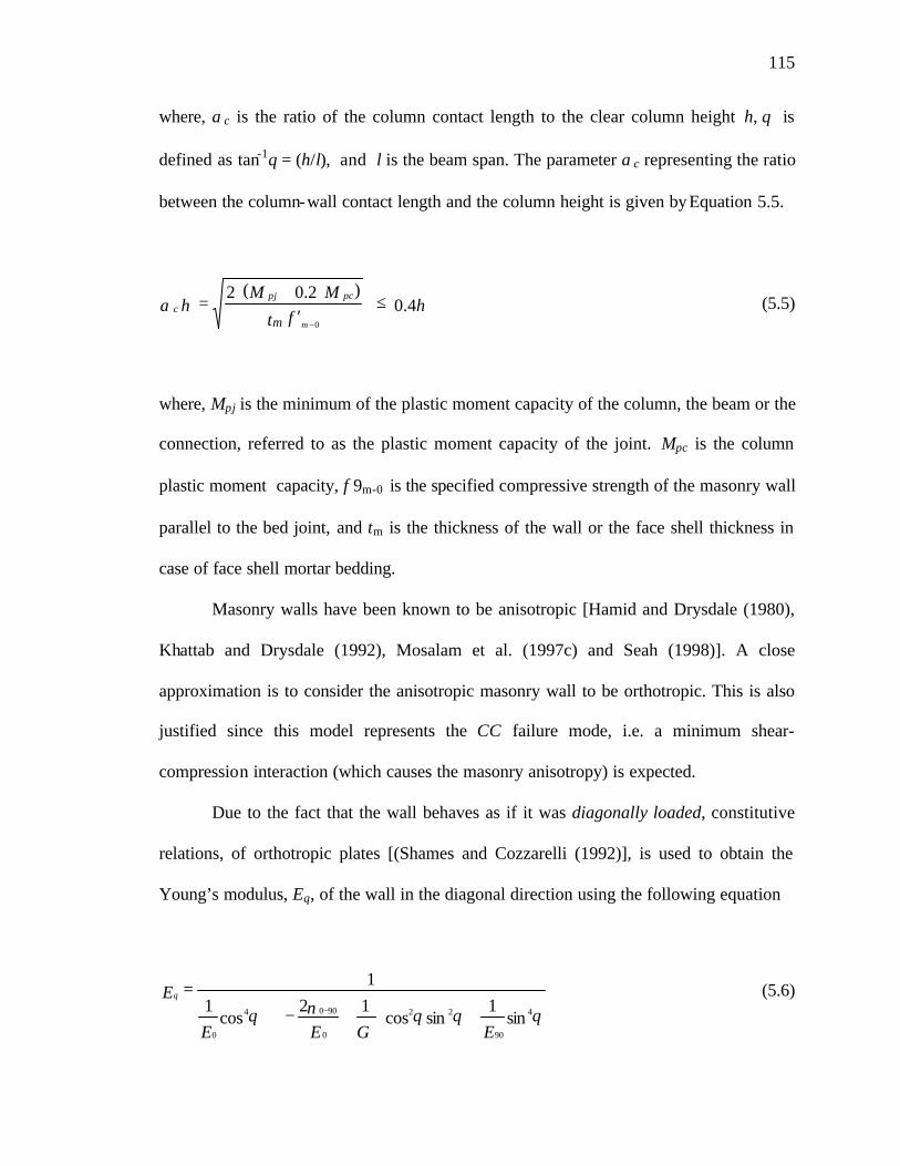
115
where, αc is the ratio of the column contact length to the clear column height h, θ is
defined as tan-1θ = (h/l), and l is the beam span. The parameter αc representing the ratio
between the column-wall contact length and the column height is given by Equation 5.5.
hft
MMh
m m
pcpjc 4.0
)2.0(2
0
≤′
+=
−
α (5.5)
where, Mpj is the minimum of the plastic moment capacity of the column, the beam or the
connection, referred to as the plastic moment capacity of the joint. Mpc is the column
plastic moment capacity, f 9m-0 is the specified compressive strength of the masonry wall
parallel to the bed joint, and tm is the thickness of the wall or the face shell thickness in
case of face shell mortar bedding.
Masonry walls have been known to be anisotropic [Hamid and Drysdale (1980),
Khattab and Drysdale (1992), Mosalam et al. (1997c) and Seah (1998)]. A close
approximation is to consider the anisotropic masonry wall to be orthotropic. This is also
justified since this model represents the CC failure mode, i.e. a minimum shear-
compression interaction (which causes the masonry anisotropy) is expected.
Due to the fact that the wall behaves as if it was diagonally loaded, constitutive
relations, of orthotropic plates [(Shames and Cozzarelli (1992)], is used to obtain the
Young’s modulus, Eθ, of the wall in the diagonal direction using the following equation
θθθνθθ
sin1
sincos12
cos1
1
4
90
22
0
9004
0 EGEE
E+
+−+
=−
(5.6)

116
where, E0 and E90 are Young’s moduli in the direction parallel and normal to the bed
joints respectively; ν0-90 is Poisson’s Ratio defined as the ratio of the strain in the
direction normal to the bed joints due to the strain in the direction parallel to the bed
joints; and G is the shear modulus.
Values of these parameters may be obtained from actual test data, information in
the literature, or Code recommendations. However, it is common to relate the initial
Young’s modulus of quasi-brittle materials such as concrete and masonry to their
ultimate compressive strength.
E90 = α f 9m-90 (5.7)
E0 = β f 9m-90 (5.8)
G = γ f 9m-90 (5.9)
But G can be approximated to
( ))1(4
)()1(4)1(2
90900
νβα
νν ++′
≅+
+≅
+≅ −fEEE
G mav (5.9-a)
where, Eav is the average Young’s modulus.

117
The reason for this suggestion to relate all parameters to f 9m-90 is that it is a common
practice as well as a standard test (ASTM E-447), to obtain the strength of masonry
prisms in a direction perpendicular to bed joints i.e. the vertical direction, which is
usually the loading direction in load-bearing. Code values for ν0-90 and ν90-0 are generally
unavailable. However, experimental data tends to show that both vary from 0.15 to 0.25
averaging 0.2.
The modulus of elasticity, E0 , parallel to a bed joint is less than the modulus of
elasticity E90 normal to bed joint due to orthotropic behavior which is typical in concrete
block masonry. Sources of orthotropy may be due to the face-shell mortar bedded
construction used and the presence of cross-webs of the masonry units used. Therefore, it
is expected that the degree of orthotropy depends on the geometry of the masonry units
used in construction.
E0 = 0.8 E90 (5.10)
An analytical study using finite element models [Seah (1998)] confirms the validity of
the above relationship. Experimental work conducted by Hamid et al. (1987) also
suggests the above relationship for concrete block masonry construction.
The elastic constants described above include effects of mortar joints and they represent
averaged wall properties. This is consistent with the macro-modeling approach for
masonry reported in the literature [LourenΗo (1996); Khattab (1993)].
Using the above values will result in simplifying Equation 5.6 as follows,

118
θα
θθαα
θα
θ
sin1
sincos3
821
cos25.1 4224
90
+
+−+
′= −f
E m (5.6-a)
or simply,
θθθθα
θsinsincos2cos25.1 4224
90
++
′= −
fE m (5.6-b)
It was also suggested by ElDakhakhni (2000) that, not only Young’s modulus will
change, but also the ultimate strength of the masonry wall in the θ direction, f 9m-θ . To
account for this direction variation, and to relate Eθ to f 9m-θ using the same factor
relating E90 to f 9m-90 , i.e.
αθ
θEf m =′ − (5.11)
The variation of the masonry strength with the loading angle is addressed by Drysdale et
al. (1999) where a complex shear-compression interaction relation was suggested
resulting from the existence of the week continuous bed joints. The inclusion of the
GFRP laminates should reduce this anisotropy since the GFRP is expected to carry the
shear tensile stresses. Therefore, and unless a more accurate method is available, it is
suggested to use Equation 5.11 to account for this variation.

119
The ACI-530-99 “Building Code Requirements for Masonry Structures”, suggests
that E90 is expressed as a function of the prism compressive strength as follows:
E90 =1000 f 9m-90 (5.12)
Indicating a value of 1000 for α, however, experimental evidence for concrete masonry
construction indicates the relationship shown in Equation 5.12 overestimates the modulus
of elasticity of masonry [Hatzinikolas et al. (1978); Hamid et al. (1987)] and a more
conservative value of α is used in this study:
E90 = 700 ???f 9m-90 (5.12-a)
To summarize the above procedure, the first step is to determine the axial strength of the
masonry prism, f 9m-90, according to ASTM E-447. Secondly, using Equation 5.12-a for
the value of α, the value of Eθ can be determined from Equation 5.6-b, and hence fθ from
Equation 5.11. Now with Eθ and fθ are known, the parameters in Fig. 5.7-a can be easily
calculated. The figure represents a suggested envelope for the cyclic stress-strain relation
for the diagonal strut formed in CMISF fa iling in CC mode.
Based on non- linear FE analyses, Eldakhakhni (2000) suggested that for monotonically
loaded CMISF, the secant Young’s modulus, in the strut stress-strain relation, at peak
load Ep is equal to half the initial Young’s modulus, Eθ , i.e.
Ep= 0.5 Eθ (5.13)

120
However, because the reversed loading causes stiffness degradation at a much higher rate
than when monotonically increasing load is applied to the frame, it is believed that for
cyclically loaded CMISF, half this value will represent the stiffness degradation under
cyclic loading more accurately, i.e.
Ep= 0.25 Eθ (5.13-a)
As shown in Fig. 5.7-a knowing Ep and fθ , it is now an easy task to determine the strain
corresponding to the end of the linear behavior, εL, and that of the peak load εp . Instead
of using the parabolic stress-strain relation shown in Fig. 5.7-a, it is suggested to
approximate it into a piecewise-linear relation, which is simpler and more practical for
analysis as shown by the thick lines in the same figure.
While a post peak strain of
ε1 = εp + 0.002 (5.14)
proved to be a valid assumption for monotonically loaded CMISF, yet a value of
ε1 = εp + 0.003 (5.14-a)
is suggested herein for cyclically loaded CMISF.

121
The post peak behavior of CMISF is highly uncertain, however the stiffness of the
descending portion of the envelope was identified for the unretrofitted and the retrofitted
walls to be, respectively,
Ed= -0.25 Eθ (15)
Ed= -0.1 Eθ (5.15-a)
These values were found using trial and error system identification to best match the
stiffness of the descending portion of the hysteresis loops envelope. These values will
lead to the ultimate strain, ε2, given by the following equations for the unretrofitted and
the retrofitted walls to be, respectively,
ε2 = ε1 + f 9m-θ / 0.25 Eθ = ε1 + 4 f 9m-θ / Eθ (5.16)
ε2 = ε1 + f 9m-θ / 0.10 Eθ = ε1 + 10 f 9m-θ / Eθ (5.16-a)
Knowing the stress strain relation along with the strut length (from the wall geometry)
and area (from Equation 5.4) makes it possible to obtain a force-deformation relation for
the strut as that shown in Fig. 5.7-b, by simply multiplying the strains εL, εP, ε1 and ε2 by
the length of the strut to obtain δL, δP, δ1 and δ2 respectively. Also multiplying the stress,

122
f 9m-θ , by the area of each strut results in obtaining Fu for the strut. The proposed model
for a typical CMISF is shown in Fig.5.8.
5.5 ELIMINATING THE DC MODE
The multiple diagonal stepped cracks of a bare masonry wall defines the strut area
by isolating it from the rest of the wall, and thus preventing stress redistribution between
the part of the wall separated by the cracks as well as speeding up the wall deterioration
due to the cyclic nature of the earthquake loading.
The retrofitting technique using GFRP forces the whole wall to act as one unit and allows
for redistribution of forces and for unstressed areas to pick up load from overstressed
ones. Eliminating the DC mode also reduces the sudden story drift associated with such
mode and hence minimizes the P-∆ effect.
The diagonal crack is resisted by the GFRP as shown in Fig. 5.9. Both the elastic and the
ultimate limit models are shown in the figure.
If the elasticity solution is used, the solution for a cube under diagonal load, [Chen
(1982)], will be a very good approximation. This solution can be applied for a diagonally
loaded wall as shown in Fig. 5.9-a. The maximum tensile stress, σt , will occur at the
center of the wall and can be approximated by
dtR
tπ
σ2
≅ (5.17)

123
where, t is the wall thickness (twice the thickness of the face shell for FSMB), R is the
diagonal load on the wall, and d can be approximated as the average of the wall
dimensions by, d=0.5(l+h) .
From the above equation, and neglecting the tensile strength of the mortar joints, the
tensile strength of the GFRP laminate per unit length perpendicular to the loading
direction (in the diagonal direction), fGFRP-(θ+90) , should be at least equal to
)cos(sinsin42
)90( θθπθ
πθ +
≅≅+−h
FdF
f uuGFRP (5.17-a)
The accuracy of this equation depends on the ratio between the loading length and the
side length of the wall. Due to the fact that the contact length is much less than the wall
dimensions and that the contact corner region, where the load is applied, is sufficiently
far from the center of the wall, where the diagonal cracking starts, it is then safe to
assume that the Saint-Venant’s principle, [Timoshenko and Goodier (1982)], applies.
That is the cracking load is not affected by the way the load is distributed over the contact
lengths. In fact many experimental observations including the test of specimen SP-2
document that these cracks are not exactly diagonal but rather on a 458 inclination
initiating at the loaded corners. This shows that Equation 5.17-a can be further simplified
to
)cos(sinsin42
45 θθπθ
π +≅≅−
hF
dFf uu
GFRP ο (5.17-b)

124
On the other hand, assuming that the ultimate limit state is reached the ultimate limit
model is shown in Fig. 5.9-b, where the wall is separated into two parts. This behavior is
similar to either to what occurs in unreinforced masonry cantilever wall subjected to
lateral load, or that occurring in the restrained racking test, [Paulay and Priestley (1992)].
The GFRP laminate will act as if it was stitching the masonry wall as shown in Fig. 5.9-b.
and the demand of the GFRP laminate, fGFRP-0 , will be
hF
hH
f uGFRP
θcos0 ==− (5.18)
where, h is the wall height, and H is ultimate lateral load on the retrofitted wall.
5.6 ELIMINATING THE SS MODE
Cracking in the masonry wall due to shear stresses is a very common type of
failure observed in URM buildings affected by earthquakes. This type of failure is mainly
controlled by the shear strength of the mortar joints and the relative values of the shear
and normal stress. Depending on these parameters, the combination of shear stresses with
vertical axial stresses can produce either cracks crossing the masonry units or debonding
along the mortar joints (also termed as shear friction failure).
The SS mode is relatively complicated to model, this is due to the uncertain value of the
friction coefficient between the masonry blocks {typically varying from 0.3 to 1.2
[Paulay and Priestley (1992)]} as well as the complex shear-compression interaction in
the masonry wall (Hamid et al. 1987). The elimination of the SS mode, which causes the

125
knee brace effect on the frame [Paulay and Priestley (1992)] is also of prime interest
since it is a sudden, non-ductile mode of failure that causes severe damage to the frame
columns at its mid height (see Fig. 5.10). It is also clear that due to the weak shear bond
strength of the mortar bed joints, causing the SS mode, the full wall capacity presented in
the CC mode could not be utilized.
The GFRP shear strength, fGFRP-τ , should be enough to prevent the SS mode of
failure presented in the form of horizontal shear slip along a bed joint to take place. It is
then required that the retrofitted bed joint can withstand this stress to safeguard against
developing the SS mode of failure. Equations 5.19 and 5.20 give the supply, fτ-s , and
demand, fτ-d, of shear force per unit length at the retrofitted bed joints, respectively,
f l
Ft = f GFRP
umos τ
θµττ −++×−
sin)( (5.19)
lF
= f ud
θτ
cos5.1− (5.20)
In this previous equation the extra shear supply of shear resulting from the friction due
normal force resulting from the wall’s own weight above the sliding bed joint, as well as
any imposed gravity loads from the top beam as it deflects is neglected due to the
uncertainty of which bed joint is weaker or where the slippage should occur, although it
is suggested to be approximately in the mid height of the wall [Pauly and Priestley
(1992)] and the shrinkage of the wall itself that might result in a loss of contact between
the top beam and the infill. In any case omitting these factors are on the safe side since
their inclusion will result in a lesser FRP ratio to carry lesser shear, and also because of
the small ratio of the walls’ weight compared to the vertical component of the strut.

126
Moreover, because of the small value of the cohesive strength (average value of
το = 0.03 f 9m-90) it suggested to neglect the cohesive strength share in supplying shear
strength for bed joints, and the lower bound of the coefficient of friction (µ = 0.3) should
be adopted for design. The strength of the GFRP should be enough to provide at least the
maximum demand of shear flow f τ–d, i.e.
f = f sd −− ττ (5.21)
f l
F =
lF
GFRPuu
τθθ
−+sin
3.0cos5.1
(5.21-a)
−=−=− θ
θθθ
θθτ cos
sin3.05.1
sincos
sin3.0
sin5.1 2
hF
h
F
hF
fuuu
GFRP (5.21-b)
The GFRP shear strength depends on both the type as well as the orientation of the fibers
within the GFRP laminate and can be determined by the standard rail test.
5.7 ELIMINATING THE FF MODE
As reported by many researchers, [Reflak and Fajfar (1991), Saneinejad and
Hobbs (1995), Mosalam et al. (1997a,b,c), and Buonopane and White (1999)], the
bending moments (see Fig. 5.11) and shearing forces distribution in the infilled frame
members cannot be replicated using a single diagonal strut (although has been used
frequently) connecting the two loaded corners. Due to the fact that the infilled frame
system will be acting as a braced frame the bending moments in the frame members

127
(frame action) will be reduced and the frame members will be subjected to higher axial
forces (truss action). Consequently, the columns, the beams, and the beam-column
connection should be designed to resist the additional axial forces resulting from seismic
actions. However, considering only the bracing effect, presented by the strut does not
show the whole picture of the frame-wall interaction. If the wall is modeled as a strut
connecting the two loaded corners, an unexpected bending moments as well as high shear
forces near the beam-column connection might occur in the actual structure, thus leading
to another form of failure. These bending moments and shearing force occur because the
actual stressed area of the wall is not a simple line connecting the two loaded corners, but
rather, it is a region connecting the vicinity of the loaded corners. Therefore, the columns,
the beams, and the beam-column connection should be designed accordingly. Three main
failure criterion or levels of design are suggested herein to prevent the FF failure mode.
These levels are termed global, intermediate and local, respectively.
In the global level, as shown in Fig 5.12-a, each infill wall is replaced by a
diagonal strut. The framed building is transformed into a braced frame dominated mainly
by truss, rather than frame, action. This global level of analysis will yield higher axial
forces with much less bending moments than those expected for framed structures. It will
also alter the whole building’s lateral stiffness, strength and response modification factor.
However, the excessive elongation of the frame members reduces the beneficial effect of
the frame, which restrains the shear distortion of the masonry wall. Consequently, the
frame columns should be designed to resist the tensile axial forces resulting from seismic
actions without yielding. And the seismic base shear attracted by the building should
128
change significantly with the inclusion of the infill walls as a result of the stiffness and
hence the natural period change.
In the intermediate level of design, a closer look into the infill wall shows that the
stressed part of the wall will cause bending moments and shearing forces because it
pushes against the frame columns as shown in Fig. 5.12-b. High normal and tangential
stresses develop along the contact lengths in the zones near to the loaded corners,
resulting in large shear forces and bending moments. The stress state induced in these
beam-column joints may cause different failure modes to the joint. Minor attention has
been given to this mode of failure, even though it has been observed in different
investigations. The failure of the beam-column joint causes unfavorable effects in the
behavior of infilled frames, because the lateral forces cannot be transferred from the floor
beam to the columns and the masonry wall. Furthermore, the contact length at the loaded
corners and the width of the equivalent strut decrease with the opening of the joint,
resulting in an increase of the stresses in the masonry wall. The columns can also fail due
to the shear forces resulting from the interaction with the infill wall. The maximum shear
forces occur along the contact length, near the loaded corners. Web or weld shear failure
can occur at the top of the tension columns, close to the beam face, as a result of the
unfavorable combination of shear and tensile axial forces. For the above mentioned
reasons, this intermediate level of design must be accounted for in the design of the frame
columns and connections by assuming that the force in the strut is distributed uniformly
over the contact length.
129
The last design level deals with the localized frame failure caused by the
retrofitted masonry infill walls. In this local design level the column flange bending
observed in specimen SP-4 and SP-6 lead to the conclusion that these flanges must be
designed to resist the forces applied by the strut, especially in the case of FSMB
retrofitted walls. The reason is that unlike unretrofitted walls which disintegrate as soon
as the web splitting occur, the GFRP keeps the masonry face shell in place even after the
web splitting, thus causing the form of damage described in section 4.6.5 of Chapter
Four. This failure is also justified based on the fact that the increased strength of the
retrofitted masonry leads to a decreased contact length (see Equation 5.5) with an
increase in the strut capacity. Using FSMB makes the problem even more pronounced,
since the whole retrofitted strut force will be applied on the column flanges from the face
shell area only not the whole area of the blocks. With the expected increased in strength,
decrease of the force application area and the stabilized face shell, this form of failure is
expected to occur more in retrofitted rather than unretrofitted infilled frames. The local
effect of the masonry infill is shown in Fig. 5.12-c.
5.8 MODELING OF TEST SPECIMENS
The proposed CC model was used to model the solid unretrofitted and retrofitted CMISF
specimens SP-2 and SP-4, respectively. The ANSYS®5.3 FE program was used to
generate the load-deflection relation of the specimens.
Because the columns bottom connections to the strong floor were semi-rigid connections,
a calibration process was needed to determine the connections rigidity. The fact that the
bottom connections were semi-rigid and hinged was concluded after observing the

130
permanent plastic rotation of the column base of specimen SP-1 by the end of the second
loading stage. Investigating the load-deflection relation (shown in Fig. 4.7-a) also showed
that the initial stiffness of the specimen fell between the elastic stiffness of the hinged and
the fixed base frame as will be discussed later. In Fig. 4.7-b, the frame deformed with
secant stiffness after the yield stared at the top connections.
The first step of the calibration of the connections was to assume a hinged connection at
the column base. The calibration was implemented by using the moment-rotation relation
for the beam-column connections shown in Fig. 5.13-a. The aim of the calibration was to
find the slope of the joints moment-rotation relation that will result in obtaining the same
stiffness expected from elastic analysis for a hinged base frame with rigid top connection.
The ultimate connection moment was calculated to be 160 kN.m. (1430 kip.in.) using the
384 MPa (55 ksi) steel, and the stiffness of the bare hinged frame obtained from elastic
analysis was 1477 kN/m (8.3 kip/in).
The second step was to verify the results of step one assuming a fixed connection at the
column base. The same moment-rotation relation obtained from the first step was used
for all four connections. The aim of this step was to verify the stiffness of this model by
comparing it to the elastic analysis assuming a fixed connection at the column base. The
fixed base frame stiffness obtained from elastic analysis was 6050 kN/m (34 kip/in).
The third step was to calibrate the moment-rotation relation for the semi-rigid column
base connection, which represents the actual case in the experiments. A relation shown in
Fig. 5.13-b was found to produce the best match for the initial stiffness of the actual bare
frame specimen, SP-1, which was 14 kip/in (2500 kN/m). Using the suggested method,
131
the envelope of the load-deflection relation of the SP-1 specimen was generated and is
shown in Fig. 5.14 along with test results for comparison.
The stress-strain and the force-deformation relations for the diagonal struts
representing the masonry wall model of the SP-2 and SP-4 specimens are shown in Fig.
5.15-a, 5.15-b, 5.16-a and 5.16-b, respectively. Equations 5.1 through 5.16 were used to
produce the load-deformation relations for specimens SP-2 and SP-4 as shown in Fig.
5.17 and 5.18, respectively along with test results for comparison. The model closely
approximate the stiffness of the CMISF up to failure and appears to overestimate the
strength of specimen SP-2 by 10 %, and underestimate that of specimen SP-4 by 7%. The
complete numerical procedure is given in Appendix-C.
5.9 CONCLUSIONS
The following conclusions resulted from the investigation:
1. The GFRP retrofitting technique enhances the infilled frame stiffness, strength,
and post-peak behavior.
2. The technique eliminates undesirable failure modes along with the uncertainties
associated with their evaluation. The technique also facilitates modeling of the wall by
minimizing the anisotropic behavior of masonry due to the weak shear strength of the
mortar joints.
3. The diagonal strut model will be adequate to model the retrofitted sys tem since it
will fail in corner crushing only with no shear failure or diagonal cracking. The
retrofitting effect is accounted for by incorporating a design parameter to account for the
stiffness, strength, and ductility increase.

132
4. The proposed analytical technique predicts the lateral stiffness up to failure, and
the ultimate load capacity of solid CMISF to an acceptable degree of accuracy. The
technique accounts for the nonlinear behavior that occurs in both the steel frame (due to
formation of plastic hinges) and in the masonry wall (due to corner crushing).
5. The technique presents a macro-model that is more easy and practical to apply
and require much less time than techniques based on treating the wall as a plate or
descretizing the wall as a series of plane stress elements interconnected by a series of
springs or contact elements.
6. In order to use this technique in actual multi-story, multi-bay frame structures, a
diagonal strut should replace each infill wall following the steps of the proposed method.
This process can be easily computerized and included into the FE programs used in
structural analysis in order to automatically generate the diagonal struts and place them in
their proper locations with their respective properties.
7. Instead of using the actual nonlinear stress-strain relation, an option which might
not be available in many structural analysis software, a simplified piece-wise linear
stress-strain relation is employed for the masonry. It is worth mentioning that this
simplification results in a less solution time, specially in multi-story 3-D structures with a
large number of DOF.

133
Fig. 5.1: Possible Effects of the Infills Depending on Earthquake Response Spectrum
Fig. 5.2: Different Failure Modes of Masonry Infilled Frames: a) Corner Crushing Mode; b) Sliding Shear Mode; c) D iagonal Cracking Mode;
d) Frame Failure Model
acce
lera
tion
Spec
tral
Tif bfT
A
Period ofvibration
B
(a) CC mode (b) SS mode
( c ) D C m o d e
P
(d ) FF mode
P
P P

134
(a) (b) Fig. 5.3: The Diagonal Tension Specimen : (a) ASTM E-519 Test Setup; (b) Shear Stress
Contours and Failure Mode Obtained Using The ANSYS®5.3 FE Model
(a) (b)
Fig. 5.4: ANSYS®5.3 FE Model of a Single panel Infilled Frame: (a) Schematic
Diagram; (b) Principal Stress Contours
Element
BEAM3 Element
CONTACT12 Element
PLANE42
P
P

135
Fig. 5.5: The Infill Wall Contact Lengths
Fig. 5.6: The Beam-Column Connection Material Model Behavior
Moment
M
φφel φpl Rotation ult
pj
Contact Lengths
P
Contact Lengths
Diagonal Strut

136
(a) (b)
Fig. 5.7: Simplified Piecewise-Linear Relations for the Diagonal Strut: (a) Stress-Strain
Relation; (b) Force-Deformation Relation
Fig. 5.8: The Proposed CMISF Model
Lε ε p
Stress
f '
m-f 'm-
21
θ
θ
Eθ
1
E
ε
Ep
ε 2
d
Strain
i
u
uF21
FK
Force
δL pδ Deformation
Kp
dK
2δ1δ
ColumnStrut
Beam
l
θ
Beam-Column Joint
h

137
Fig. 5.9: Tensile Stresses Resulting in The Diagonal Cracking:
a) Elastic Model; b) Ultimate Limit Model
Fig. 5.10: Knee Brace Effect of the Frame Caused by the SS Mode
(a)(b)
H
R
σ
d
R
ttσ
tσσt
h

138
Fig. 5.11: Bending Moment Diagrams for a Different Bays in Multi-Story Infilled Frame
Building
(a)
B
CD
GH
A
EF
G
E
H C D
AF B

139
(b)
(c)
Fig. 5.12: Different Modeling Levels of the Infill Wall within CMISF Buildings : a) Global Model, b) Intermediate Model, c) Local Model
A-A
α
Sec. A-A

140
(a) (b)
Fig. 5.13: Behavior of Bare Frame Model Joints: a) Top Joint, b) Bottom Joint
Fig. 5.14: Specimen SP-1 Model with the Test Results
0.0007(rad)RotationRotation
(rad)0.05
Moment(kip.in)
1430
(kip.in)Moment
1430
-300
-200
-100
0
100
200
300
-100 -75 -50 -25 0 25 50 75 100
Displacement (mm)
Lo
ad (
kN)
Model Test

141
(a) (b) Fig. 5.15: Behavior of Specimen SP-2 Model Diagonal Strut: a) Stress-Strain Relation, b)
Force-Deformation Relation
(a) (b)
Fig. 5.16: Behavior of Specimen SP-4 Model Diagonal Strut: a) Stress-Strain Relation, b) Force-Deformation Relation
312
312
8.72
1.78
0.72
0.89
5.72
Stress(Ksi)
1250
107
1.525
(Kips)Force
Strain (10 )10.12
106
0.125−3
53
1.00
428 107
Deformation (in)1.775
218
545
8.72
Stress
5.720.72
3.11
1.56
(Ksi)
2180
61
1.525
Force(Kips)
Strain (10 )22.86 1.00−3 0.125
152
76
610 152
Deformation (in)4.00

142
Fig. 5.17: Specimen SP-2 Model with the Test Results
Fig. 5.18: Specimen SP-4 Model with the Test Results
-800
-600
-400
-200
0
200
400
600
800
-150 -125 -100 -75 -50 -25 0 25 50 75 100 125 150
Displacement (mm)
Load
(kN
)
Test Model
-600
-400
-200
0
200
400
600
-100 -75 -50 -25 0 25 50 75 100
Displacement (mm)
Load
(kN
)
Model Test

143
CHAPTER 6: Summary, Conclusions and Recommendations
6.1 SUMMARY
Masonry infill walls in frame structures have been long known to affect strength,
stiffness and post-peak behavior of the infilled frame structures. In seismic areas,
ignoring the composite action is not always on the safe side, since the interaction between
the wall and the frame under lateral loads dramatically changes the dynamic
characteristics of the composite structure and hence its response to seismic loads creating
a major source of hazard during seismic events.
The study conducted herein focuses on investigating the retrofitting effect of
hollow concrete masonry- infilled steel frames (CMISF) subjected to in-plane lateral loads
using glass fiber reinforced plastic (GFRP) laminates that are epoxy-bonded to the
exterior faces of the infill walls. Chapter Two summarizes the experimental and
theoretical research work conducted in the area of infilled frames. It is now widely
recognized that masonry infill walls used for cladding and/or partition in buildings,
significantly alter their seismic response, and their effect in changing the stiffness, the
ultimate lateral load capacity as well as the ductility supply of the building system should
be accounted for in analysis and design.
The subsequent study involves three main phases. The first phase, described in
Chapter Three, studies the in-plane behavior of face shell mortar bedding (FSMB)
unreinforced masonry (URM) wall subassemblages strengthened with different GFRP
composite laminates. A total of fifty seven URM assemblages were tested under different

144
loading conditions. Parameters such as the type of fibers, the number of plies, and the
fibers orientation were investigated. Results showed that the application of GFRP
laminates on URM has a great influence on strength, post peak behavior, as well as
failure modes. An increase of 90% for compressive strength was achieved using the
GFRP laminates and the shear strength increased by fourteen folds.
The second phase, presented in Chapter Four, focuses on enhancing the in-plane
seismic behavior of URM infill walls when subjected to displacement controlled cyclic
loading. Six full scale 3,60033,000 mm (12 ft310 ft) single story single bay steel frames
with different infill configurations were tested. The retrofitting technique using GFRP
laminates aims at creating an engineered infill wall with a well defined failure mode and
a stable post peak behavior as well as containing the hazardous URM damage and
preventing catastrophic failure. Results showed that the GFRP prevented both shear and
tension cracking by supplying the required tensile strength. The GFRP also increased the
lateral load capacity and enhanced the post peak behavior by means of stabilizing the
masonry face shell and preventing its out-of-plane spalling. The stabilizing allows the
wall to carry more load and prevents sudden drop in the load carrying capacity.
The third part of the study presents an analytical model proposed for the analysis of the
unretrofitted and GFRP-retrofitted masonry infilled frames. In this method, each masonry
wall was replaced with a nonlinear, compression-only, diagonal strut that estimates the
stiffness and the lateral load capacity of CMISF failing in corner crushing (CC) mode.
The diagonal strut force-deformation characteristics were based on the orthotropic

145
behavior of the masonry wall. A proposed method for designing the GFRP retrofitted
walls in order to prevent various failure modes is also presented.
6.2 CONCLUSIONS
The following conclusions resulted from the current investigation:
1. By eliminating the shear failure using properly selected GFRP laminates, the long
known anisotropy of masonry resulting from the complex shear-compression
interaction along the weak mortar joints [Hamid and Drysdale (1980)] can now be
eliminated.
2. The GFRP laminates will produce an engineered masonry-GFRP composite wall in
which the masonry face shells provide the compressive strength and the GFRP
laminate supplies the required tensile and shear strengths. The GFRP laminates will
also improve the compression strength of the face shells by supplying the tensile
strength required to stabilize the out-of-plane buckling of the individual face shells,
thus preventing the out-of-plane buckling failure. The laminates also confine the face
shells against in-plane tensile failure, thus allowing it to carry higher loads.
3. Eliminating the anisotropic nature of masonry walls will also facilitates modeling by
means of eliminating undesirable failure modes along with the uncertainties
associated with their evaluation.
4. Similar to the retrofitted assemblage, the GFRP laminated maintain the full-scale wall
structural integrity and prevented collapse and debris fallout, contain and localize the
damage of the URM walls even after ultimate failure. No signs of distress were
evident throughout the wall except at the vicinity of the corners. This keeps the face

146
shells of all the blocks as one plate, thus reducing the possibility of the external walls
or partitions spalling, which, in itself, a major source of hazard during earthquakes
even if the whole structure remains safe and functioning.
5. The masonry-GFRP composite walls do not fail catastrophically as their URM
counterparts. The GFRP laminates resulted in a gradual prolonged failure, a stronger
wall, more energy dissipation and apparent post peak strength. This will result in a
larger response modification factor than that typically selected for the analysis of
URM wall structures.
6. By supplying the shear strength at the mortar joints, the laminate should eliminate the
effects of poor workmanship, initial cracks and defects, as well as mortar
deterioration by weathering, shrinkage and aging. The laminate will also serve as an
external reinforcement for unreinforced or under reinforced walls, thus providing a
quick and cost-effective solution to conform to emerging seismic codes requirements.
7. The diagonal strut model will be adequate to model the retrofitted system since it
will fail in corner crushing only with no shear failure or diagonal cracking. The
retrofitting effect is accounted for by incorporating design parameter to account for
the stiffness, strength, and ductility increase.
8. The proposed analytical technique predicts the lateral stiffness up to failure, and the
ultimate load capacity of solid CMISF to an acceptable degree of accuracy. The
technique accounts for the nonlinear behavior that occurs in both the steel frame (due
to formation of plastic hinges) and in the masonry wall (due to corner crushing).
9. The technique presents a macro-model that is more easy and practical to apply and
require much less time than techniques based on treating the wall as a plate or

147
descretizing the wall as a series of plane stress elements interconnected by a series of
springs or contact elements.
10. In order to use this technique in actual multi-story, multi-bay frame structures, a
diagonal strut should replace each infill wall following the steps of the proposed
method. This process can be easily computerized and included into the FE programs
used in structural analysis in order to automatically generate the diagonal struts and
place them in their locations with their respective properties.
11. Instead of using the actual nonlinear stress-strain relation, an option, which might not
be available in many structural analysis software, a simplified piece-wise linear
stress-strain relation is employed for the masonry. It is worth mentioning that this
simplification results in a less solution time, specially, in multi-story 3-D structures
with large number of DOF.
6.3 RECOMMENDATIONS FOR FUTURE WORK
The investigation of the effect of retrofitting infilled frames using GFRP laminates is far
from complete. It is believed, however, that this research provides a milestone in the
effort to utilize FRPs for structural strengthening of the masonry infill walls. The
following recommendations for future work are suggested:
1. Investigate the use of different composite fabrics to retrofit full-scale infill walls,
including varying the fiber orientations and the fiber reinforcement ratios.
2. Experimentally study the FRP effectiveness of retrofitting infill walls containing
different openings configurations such as for windows and unsymmetrical door openings,
and the effect of varying the frames strength.

148
3. Investigating different surface preparation methods and amount of impregnating
resins is also needed. There is a predisposition in the construction industry to use the
impregnating resins, used for bonding the fibers, to prime the masonry surface. This is
attributed to economical reasons because the amount of required primer increases due to
the high initial rate of absorption of masonry.
4. Investigate the retrofitting of multi-story and/or multi-bay infilled frames using FRP
laminates.
5. Provide design guidelines of the FRP-masonry composite walls in order to optimize
the selection of the composite materials to retrofit URM infilled frames. This possibly
entails further assemblage testing in order to study the effect of various laminates
accompanied with a microscopic level of FE modeling to investigate the different failure
mechanisms for symmetrical and unsymmetrical retrofit where the laminates are placed
on one side only, etc.
149
LIST OF REFERENCES
Adham, S. A. (1994) “Impact of Infilled Masonry Walls on the Response of Building in Moderate Seismic Zones,” Proceedings of the NCEER Workshop on Seismic Response of Masonry Infills, NCEER-94-0004, pp. 2-23 to 2-29. Albert, M. L., Elwi, A. E. and Cheng, J. J. R. (2001) “Strengthening of Unreinforced Masonry Walls Using FRPs” Journal of Composites for Construction, ASCE Vol. 5, No. 2, May ATC-24 (1992) “Guidelines for Cyclic Seismic Testing of Components of Steel Structures” Prepared by Helmut Krawinkler for Applied Technology Council 555 Twin dolphin Drive, Suite 550 Redwood City, CA, 94065 American Institute of Steel Construction (AISC), Inc. (1998), “Load & Resistance Factor Design- Structural Members, Specifications & Codes,” Manual of Steel Construction, second edition, AISC.
American Society for Testing and Materials, ASTM C 90-92b, “Standard Specification for Load-Bearing Concrete Masonry Units,” Annual Book of ASTM Standards, Vol. 04.05, West Conshohocken, Pennsylvania.
American Society for Testing and Materials, ASTM C 109-92, “Standard Test Method for Compressive Strength of Hydraulic Cement Mortars,” Annual Book of ASTM Standards, Vol. 04.01, West Conshohocken, Pennsylvania.
American Society for Testing and Materials, ASTM C 140-91, “Standard Test Methods for Sampling and Testing Concrete Masonry Units,” Annual Book of ASTM Standards, Vol. 04.05, West Conshohocken, Pennsylvania.
American Society for Testing and Materials, ASTM C 270-92a, “Standard Specification for Mortar for Unit Masonry,” Annual Book of ASTM Standards, Vol. 04.05, West Conshohocken, Pennsylvania.
American Society for Testing and Materials, ASTM D 3039/D 3039M-93, “Standard Test Method for Tensile Properties of Polymer Matrix Composite Materials,” Annual Book of ASTM Standards, Vol. 15.03, West Conshohocken, Pennsylvania.
American Society for Testing and Materials, ASTM E 447-92b, “Standard Test Methods for Compressive Strength of Masonry Prisms,” Annual Book of ASTM Standards, Vol. 04.05, West Conshohocken, Pennsylvania.
American Society for Testing and Materials, ASTM E 519-81, “Standard Test Method for Diagonal Tension (Shear) in Masonry Assemblages,” Annual Book of ASTM Standards, Vol. 04.05, West Conshohocken, Pennsylvania.
150
Amrhein, J. E., anderson, J.C., and Robles, V.M., (1985) “Masonry Saves Lives in Mexico Earthquake”. Masonry Design West, (Nov.-Dec.)
Amos, K. A. (1986). “The Shear Strength of Masonry Infilled Steel Frames” M.Sc. thesis. Dept. of Civil Engineering, University of New Brunswick, Fredericton, N.B. Axely, J. W. and Bertero, V.V. (1979)”Infill Panels: Their Influence on Seismic Response of Buildings” EERC repot 79-28 Earthquake Engineering Research Center, University of California, Berkeley ANSYS®5.3, (1996), ANSYS® Inc. 201 Johnson Road, Houston, PA, 15342-1300. Barau, H. K., and Mallick, S. K., (1977) “Behavior of Mortar Infilled Steel Frames under Lateral Load” Building and Environment, Pergamon Press, UK. Vol 12, pp. 263-272. Buonopane, S. G., and White, R. N., (1999). “Pseudodynamic Testing of Masonry Infilled Reinforced Concrete Frame”, Journal of Structural Engineering, ASCE, 125(6), 578-589. Chen W. F., (1982) “Plasticity in Reinforced Concrete” McGraw-Hill, , New York, NY, USA Chen, W. F., and Lui, E. M., (1991). “Stability Design of Steel Frames”, CRC Press. Colombo, A., Negro, P. and Verzeletti, G. (2000) “Improving Ductility and Energy Dissipation Capacity by Means of Polymeric Nets” Proceedings of the 12th World Conference on Earthquake Engineering, #1910 on CD-ROM, New Zealand Comite Euro-International Du Beton, (1996). “RC Frames Under Earthquake Loading” State of the art report. Tomas Telford Services Ltd, 1 Heron Quay, London E14 4JD. Dawe, J. L., and Charalambous, P. D., (1983) “Finite Element Analysis for Wall-Frame Interaction” Proceedings, Eight International Loadbearing Brickwork Symposium, British Ceramic Society, Stoke-on-Trent. UK. Dawe, J. L., and Seah, C. K., (1989) “Behavior of Masonry Infilled Steel Frames” Canadian Journal of Civil Engineering, Vol. 16, No. 6. pp. 865-876 Decanini, L.D., Gavarini, C. and Mollaioli, F. (1994) “Strengthening of Frame Buildings with infill Masonry” Proceedings of the Italian-French symposium on strengthening and repair of structures in seismic area, Nice, France
Drysdale, R. G., Hamid, A. and Baker L. R. (1999) “Masonry Structures: Behavior and Design,” second edition, The Masonry Society, Boulder, Colorado.
Durrani, A.J. and Luo, Y.H. (1992) “Seismic Retrofit of Flat Slab Buildings with Masonry Infills” Proceedings of the 10th World Conference on Earthquake Engineering

151
Ehsani, M. R., Saadatmanesh, H. and Al-Saidy, A. (1997) “Shear Behavior of URM Retrofitted with FRP Overlays,” Journal of Composites for Construction, ASCE, Vol. 1, No. 1, February, pp. 17-25.
Ehsani, M. R., Saadatmanesh, H., and Velazquez-Dimas, J. L. (1999) “Behavior of retrofitted URM Walls under Simulated Earthquake Loading” Journal of Composites for Construction, ASCE, 3(3), 134–142.
Eldakhakhni, W. W. (2000) “Non-Linear Finite Element Modeling of Concrete Masonry-Infilled Steel Frame,” M.Sc. thesis, Civil and Architectural Engineering Department, Drexel University, Philadelphia. El-Dakhakhni, W. W., Elgaaly, M., and Hamid, A.A., (2001) “Finite Element Modeling of Concrete Masonry-Infilled Steel Frame,” 9th Canadian Masonry Symposium, The University of New Brunswick, Canada. FEMA-273, (1997) “NEHRP Guidelines for Seismic Rehabilitation of Buildings” Federal Emergency management Agency
Flanagan, R. D., Bennett, R. M., and Barclay, G. A., (1999). “In-plane Behavior of Structural Clay Tile Infilled Frames”, Journal of Structural Engineering, ASCE, 125(6), 590-599. Hakam, Z, H. R. (2000) “Retrofit of Hollow Concrete Masonry Infilled Steel Frames Using Glass Fiber Reinforced Plastic Laminates” Ph.D. thesis, Civil and Architectural Engineering Department, Drexel University, Philadelphia. Hamid, A.A., (1978) “Behaviour Characteristics of Concrete Masonry.” Ph.D. Thesis, McMaster University, Hamilton, Ontario, Canada. Hamid, A.A., and Drysdale, R.G. (1980). “ Concrete Masonry Under Combined Shear and Compression Along the Mortar Joints.” ACI journal September-October , 314-320. Hamid, A. A., Ziab, G., and El Nawawy, O., (1987) “Modulus of Elasticity of Concrete Masonry” Fourth North American Masonry Conference. University of California at Los Angeles, Paper 7. Hamoush, S. A. McGinley, M. W. Mlakar, P. Scott, D. and Murray, K. (2001) “Out-of-Plane Strengthening of Masonry Walls with Reinforced Composites” Journal of Composites for Construction, ASCE Vol. 5, No. 3, August Hamid, A. A., Mahmoud, A. D. S., and El Magd, S. A. (1994). “Strengthening and Repair of Unreinforced Masonry Structures: State-of-the-art” Proceedings of the 10th Int. Brick and Block Masonry Conf., Elsevier Applied Science, London, Vol. 2, 485–497.

152
Haroun, M. A., Ghoneam, E. H. and Salama, A. E. (1996) “Seismic Strengthening of Masonry-Infilled Frames by Fiber Composites” 1st Middle East workshop on structural composites, Sharm El-Shiekh, Egypt Hatzinikolas, M. A., Longworth, J., and Warwaruk, J., (1978) “Concrete Masonry Walls” Report No.70, Department of Civil Engineering, University of Alberta, Edmonton. Hendry, A., (1981) “Structural Brickwork” Macmillan, London. Holmes, M., (1961) “Steel Frames with Brickwork and Concrete Infilling” Proceedings of the Institution of Civil Engineers, Vol. 19, pp. 473-478. Holmes, M., (1963) “Combined Loading on Infilled Frames” Proceedings of the Institution of Civil Engineers, Vol. 25, pp. 31-38. Islam, M. S., Kim, H. I. and Maniar, F. (1994) “Seismic Retrofit of Two Historic Steel Buildings with Unreinforced masonry Infill Walls” Proceedings of the 5th national conference on earthquake engineering, Oakland, CA, USA Kadir, M. R. A., (1974) “The Structural Behavior of Masonry Infilled Panels in Framed Structures” Ph.D. Thesis, Department of Civil Engineering, University of Edinburgh. Kappos, A. J. (2000) “Seismic Design and Performance Assessment of Masonry Infilled R/C Frames” Proceedings of the 12th World Conference on Earthquake Engineering, #989 on CD-ROM, New Zealand Khattab, M. ,and Drysdale, R. G. (1992). “Test of Concrete Block Masonry under Biaxial Tension-Compression”, Proeedings of the 6th. Canadian Masonry Symp., University of Saskatchewan, Saskatchewan, Canada, 645-656. Kolsch, H. (1998). “Carbon Fiber Cement Matrix (CFCM) Overlay System for Masonry Strengthening” Journal of Composites for Construction, ASCE, 2(2), 105–109. Laursen P.T., Seible F., Hegemier G.A., and Innamorato D, (1995) “Seismic Retrofit and Repair of Masonry Walls with Carbon Overlays” Non-Metallic (FRP) Reinforcement for Concrete Structures, edited by L. Taerwe, RILEM, pp. 616-627. Liauw, T. C., and Kwan, K. H., (1983) “Plastic Theory of Non-Integral Infilled Frames” Proceedings of the Institution of Civil Engineers, Part 2, Vol. 75, pp. 379-396. Liauw, T. C., and Lo, C.Q., (1988) “Multi-bay Infilled Frames without Shear Connectors” ACI structural journal. July-August 1988, pp.423-428. LourenΗo, P. B., (1996) “Computational Strategies for Masonry Structures” Delft University Press, Thesis, Delft University of Technology, The Netherlands.
153
LourenΗo, P. B., and Rots, J. G., (1997) “A Solution for the Macro-Modeling of Masonry Structures” 11th International Brick/Block Masonry Conference. Tongji University, Shanghai, China. pp. 1239-1249. Madan, A., Reinhorn, A. M., Mander, J. B., and Valles, R.E. (1997) “Modeling of Masonry Infill Panels for Structural Analysis” ASCE Journal of Structural Division, Vol. 123, No. ST10, pp. 1295-1302. Mainstone, R. J., (1971) “On the Stiffness and Strengths of Infilled Frames”, Proceedings of the Institution of Civil Engineers, Supplement IV, pp 57-90. Mallick, D. V., and Severn, R. T., (1967) “The Behavior of Infilled Frames under Static Loading” Proceedings of the Institution of Civil Engineers, Vol. 38, pp 639-656 Mander, J.B and Nair, B. (1994). “Seismic Resistance of Brick-Infilled Steel Frames with and without Retrofit” TMS journal February,24-37. Manos, C. J., Thaumpta, J., and Bilal, Y., (2000) “Influence of Masonry Infills on the Earthquake Response of Multi-Story RC Structures” Proceedings of the 12th World Conference on Earthquake Engineering, #112 on CD-ROM, New Zealand Masonry Standards Joint Committee (1999) “Building Code Requirements for Masonry Structures” (ACI 530-99/ASCE 5-99/TMS 402-99). American Concrete Institute. Detroit, Michigan, USA. McBride, R. T., (1984). “The Behavior of Masonry Infilled Steel Frames Subjected to Racking”, M.Sc. thesis, Dept. of Civil Engineering., University of New Brunswick, Fredericton, NB, Canada. Mosalam, K., White, R. N., and Gergely, P., (1997-a). “Seismic Evaluation of Frames with Infill Walls Using Quasi-static Experiments”. NCEER-97-0019. Mosalam, K., White, R. N., and Gergely, P., (1997-b). “Seismic Evaluation of Frames with Infill Walls Using Pseudo-dynamic Experiments”. NCEER-97-0020. Mosalam, K., White, R. N., and Gergely, P., (1997-c). “Computational Strategies for Frames with Infill Walls: Discrete and Smeared Crack Analyses and Seismic Fragility”. NCEER-97-0021. Murty, C.R.V. and Jain, S.K., (2000) “Beneficial Influence of Masonry Infill Walls on Seismic Performance of Reinforced Concrete Frame Buildings” Proceedings of the 12th World Conference on Earthquake Engineering, #1790 on CD-ROM, New Zealand Myers, J.J., (2000). “An In-Situe Evaluation of FRP-Strengthened Unreinforced Masonry Walls Subjected to Out-of-Plane Loading” Structures Congress, ASCE, Philadelphia.
154
Paulay, T. and Priestley, M. J. N. (1992) “Seismic Design of Reinforced Concrete and Masonry Buildings,” John Wiley & Sons, Inc., New York, NY, USA.
Pincheira, J. A. and Jirsa, J. O. (1995) “Seismic Response of RC Frames Retrofitted with Steel Braces or Walls,” Journal of Structural Engineering, ASCE, Vol. 121, No. 8, August, pp. 1,225-1,235.
Prawel S.P., and Reinhorn A.M., (1985) “Seismic Retrofit of Structural Masonry using a Ferrocement Overlay” Proceedings of the Third North American Masonry Conference Polyakov, S. V., (1956) “Masonry in Framed Buildings” (Godsudarstvenoe Isdatel' stvo Literatury Po Stroidal stvui Architecture. Moscow, 1956). Translated by G. L. Cairns in 1963. National Lending Library for Science and Technology, Boston Spa, Yorkshire, U.K. Polyakov, S. V., (1960) “On the Interaction between Masonry Filler Walls and Enclosing Frame when Loaded in the Plane of the Wall” Earthquake Engineering. Earthquake Engineering Research Institute, San Francisco, CA, pp. 36-42 Porter, M. L., and Tremel, P.M. (1987) “Sequential Phased Displacement Procedure for TCCMAR Testing” Third meeting of the joint Technical Coordinating Committee on Masonry Research, US-Japan Coordinated Earthquake Research Program, Sapporo, Japan Rathbun, J. C., (1938) “Wind Forces on a Tall Building” Proceedings, American Society of Civil Engineers, Vol 64. pp. 1335 - 1375. Reinhorn, A. M., Prawel, S. P. and Jia, Z. H. (1985) “Experimental Study on External Ferrocement Coating for Masonry Walls” Journal of Ferrocement, Vol.15, No.3 Richardson, J., (1986). “The Behavior of Masonry Infilled Steel Frames”. M.Sc. thesis, Dept. of Civil Engineering, University of New Brunswick, Fredericton, NB, Canada. Riddington, J. R., and Stafford Smith, B., (1977) “Analysis of Infilled Frames Subjected to Racking with Design Recommendations” The Structural Engineer, Vol. 55, No. 6, pp 263-268. Sachanski, S., (1960) “Analysis of the Earthquake Resistance of Frame Buildings Taking into Consideration the Carrying Capacity of the Filling Masonry” Proceedings of the Second World Conference on Earthquake Engineering, Vol. 3, Tokyo, pp. 2127-2141. Saneinejad A., and Hobbs, B., (1995). “Inelastic Design of Infilled Frames” Journal of Structural Division, ASCE , 121(ST4), 634-650.

155
Seah, C. K. (1998) “A Universal Approach for the Analysis and Design of Masonry Infilled Frame Structures,” Ph.D. thesis, The University of New Brunswick, Canada, December Shames, I.H., and Cozzarelli, F.A (1992). “Elastic & Inelastic Stress Analysis” Prentice Hall, Upper Saddle River, NJ, 07632, USA. Stafford Smith, B., (1962) “Lateral Stiffness of Infilled Frames” ASCE Journal of Structural Division, Vol. 88, No. ST6, pp. 183-199. Stafford Smith, B., (1966) “Behavior of Square Infilled Frames” ASCE Journal of the Structural Division, Vol. 92, No. ST1, pp. 381-403. Stafford Smith, B., and Carter, C., (1969). “A Method of Analysis for Infilled Frames” Proc., the Inst. of Civil Engineers, 44, 31-48. Taghdi M., Bruneau M., and Saatcioglu M., “Seismic Retrofitting of Low-Rise Masonry and Concrete Walls using Steel Strip,” ASCE Journal of Structural Engineering September 2000, pp. 1017-1025. Thomas, F. G., (1953) “The Strength of Brickwork” The Structural Engineer, Part 2, Vol. 36, pp. 35-41. Timoshenko and Goodier (1982). “ Theory of Elasticity” McGraw-Hill, , New York, NY, USA. Triantafillou, T. C. (1998) “Strengthening of Masonry Structures using Epoxy-Bonded FRP Laminates” Journal of Composites for Construction, ASCE, Vol. 2, No. 2, May, pp. 96-104.
Weeks, J., Seible, F., Hegemier, G. and Priestly, M. J. N. (1994) “The U.S.-TCCMAR Full-scale Five-story Research Building Test, Part V- Repair and Retest” Report No. 9.4-5, Department of Applied Mechanics and Engineering Sciences, University of California, San Diego, January Wood, R. H., (1958) “The Stability of Tall Buildings” Proceedings of the Institution of Civil Engineers, Vol. 11, pp. 69-102. Velazquez-Dimas, J. I., Ehsani, M. R. and Saadatmanesh, H. (2000) “Out-of-Plane Behavior of Brick Masonry Walls Strengthened with Fiber Composites,” ACI Structural Journal, Vol. 97, No. 3, May-June, pp. 377-387. Yong, T. C., (1984) “Shear Strength of Masonry Panels in Steel Frames” M.Sc. thesis, Department of Civil Engineering, University of New Brunswick, Canada.