experimental and numerical analysis of a load distribution
TRANSCRIPT

International Journal of Advanced Technology and Engineering Exploration, Vol 6(51)
ISSN (Print): 2394-5443 ISSN (Online): 2394-7454
http://dx.doi.org/10.19101/IJATEE.2019.650006
30
Experimental and numerical analysis of a load distribution along the length of
contact in involute spline shaft
Swapnil B. Patil1*
and S. R. Patil2
ME Student, Department of Mechanical Engineering, AISSMS COE, SPPU, Pune, Maharashtra, India1
Assistant Professor, Department of Mechanical Engineering, AISSMS COE, SPPU, Pune, Maharashtra, India2
Received: 14-December-2018; Revised: 22-February-2019; Accepted: 25-February-2019
©2019 Swapnil B. Patil and S. R. Patil. This is an open access article distributed under the Creative Commons Attribution (CC
BY) License, which permits unrestricted use, distribution, and reproduction in any medium, provided the original work is
properly cited.
1.Introduction The involute spline hub connection under pure
torsion loading case aims to find the load distribution
along the length of spline and localized stress area on
teeth. Spline shaft for transmitting a torque is used.
Properly align connection without sliding and angular
misalignment is used. When the shaft is connected to
a pure and study torque load, then the connection is
under pure torsion loading condition. In pure torque
transmitting case the spline teeth are under shear
stress. In this paper the location for the stress along
the spline length for partial contact length and the
load distribution along the length of spline teeth is
evaluated. Load distribution along the length of
spline is measured by designing an experimental
setup. The setup consists of spline connection
mounted on the fixture. To apply a torque loading
arm is used; strain gauges are installed on the teeth to
measure the strain. The electronic system has facility
to monitor the strains measured on the teeth.
*Author for correspondence
The study on the fix contact length for the spline hub
connection is done in this paper. The study for the
various contact length and load variation is done. The
effect of change in contact length for the various
torque cases is investigated. The experimental setup
is designed with single channel strain indicator
system which is helpful to determine the strain at the
connection. For measuring a strain at the connection,
the strain gauges with a compact size is used. The
strain gauges mounted on the spline teeth along its
length to predict the localized stress along the length.
The spline shaft is designed with the En19 material
characteristics and hub as well. Involute spline
geometry is defined, as the involute spline geometry
have a more load carrying capacity compared with
the rectangular and traphizoidal spline geometry.
Experimental analysis in completed by using the
strain gauge technique. The compact strain gauges
are used along with the strain indicating device. The
reading for strain value at entry, mid, exit portion of
the spline length is taken and with the help of these
strain stresses at that location is calculated from the
Research Article
Abstract In mechanical drive system for transmitting power the spline hub connections are widely used. Finite element method is
used to find the load distribution along the length of spline, for analysis a frictional contact with 0.15 coefficient of
friction and pure penalty method is used. For finding the load distribution three location is defined as entry, mid and exit.
It is observed for partial spline contact over a length, two zones are created as contact and free zone. The analysis is
performed for five partial contact length and torque respectively and it is observed that there is average 10.82% stress
reduction at the entry point of spline and 64.60% stress reduction at the middle point of spline. There is no change is in
the stress at the exit of a spline. The nature of the stresses in contact zone is uniformly decreasing toward the free zone
and the stresses in free zone are also uniformly decreasing toward an exit of spline. The highly localized stress is
identified in free zone probably at the end of percentage length of contact and this stresses uniformly decreasing toward
the shoulder of spline shaft in the free zone. At the end of spline contact the stresses are high and this causes the failure
of spline at this location.
Keywords Involute spline shaft, Load distribution, Contact length, En19 alloy steel, Finite element analysis, Experimental stress
analysis.
International Journal of Advanced Technology and Engineering Exploration, Vol 6(51)
31
hooks law. The experiments are performed for the 50,
60, 70, 80, 90 mm spline contact with 86.6, 111.1,
135.63, 160.15, 184.68 Nm torque variations. The
splines are tested under static pure torsion loading
case by using the 15 to 35 kg with a load step of 5 kg.
The objectives of this paper are as follows:
1. To find the variation in load distribution along the
length of spline contact for various contact length
and torque levels combinations.
2. To predict the highly localized stress location
along the length of spline contact.
2.Literature review Hong et al. [1] Study the load distribution analysis of
clearance-fit spline joints using finite elements and
identified that load distribution along the spline
length is different in case of spur and helical loading
case. Pure torsion loading results showed identical
load distributions on all spline teeth, with each tooth
exhibiting non-uniform load in axial direction. Hong
et al. [2] presented work on a semi analytical load
distribution model for side-fit involute splines. The
work aims to define semi analytical model to predict
load distributions of spline joints. Adey et al. [3]
developed an analysis tools for spline couplings. This
study describes the development of new analysis
technique to predict the contact stress and load
transfer mechanism in spline coupling. Khalik and
Faidh-Allah [4] studied experimental and numerical
stress analysis of involute splined shaft. This induced
splined shaft teeth contact and bending stresses have
been investigated numerically using finite element
method.
Tjernberg [5] presented work on the load distribution
in axial direction in spline coupling; in this study the
stress concentration factor at the teeth is considered.
The stress concentration factor changes as the contact
length changes. Barrot et al. [6] presented work on
determined both radial pressure distribution and
torsional stiffness of involute spline couplings. The
analytical method is used to investigate the
distortions of involute spline teeth. Barrot et al. [7]
presented work on the extended equations of load
distribution in the axial direction in a spline coupling
to study of axial torque transfer in a spline coupling.
The model developed by Tatur has been extended in
order to consider different loading cases and
geometries. AL-Shammaa and Kadhim [8] observed
the effect of engagement length and spline
parameters variation with cyclic crack growth rate in
a spline coupling subjected to cyclic torsional impact
have been investigated analytically and
experimentally.
Ding et al. [9] work on finite element simulation of
fretting wear fatigue interaction in spline couplings.
This study describes a finite element based method
for simulating the effects of material removal,
associated with fretting wear, on fretting fatigue
parameters in a spline coupling. Shen et al. [10] study
plain fretting fatigue competition in spline shaft-hub
connection. In this study the dynamically loaded
spline shaft-hub connection that without macro
relative movement between shaft and hub. Barsoum
et al. [11] analyzed the torsional strength of hardened
splined shafts. This study describe increasing the
number of teeth, which corresponds to increasing the
dedendum radius and keeping the addendum radius
constant, increases the torsion strength of the shaft.
Margineanu et al. [12] presented work on analytic
and experimental study of the load distribution on
spline joints length considering the contact rigidity of
the bearing surfaces. In this study the load transfers
by the spline under pure torsion condition.
Cuffaro et al. [13] identified the damage in spline
coupling teeth by means of roughness parameters.
The aim of this work is to use the surface roughness
to identify the fretting damage on spline coupling
teeth. Cura and Mura [14] presented a work on
experimental procedure for the evaluation of tooth
stiffness in spline coupling including angular
misalignment. Tooth stiffness is a very important
parameter in studying both static and dynamic
behavior of spline couplings and gears. Xue et al.
[15] modified the methodology of fretting wear in
involute spline. This work gives the information
about developing a method on predicting the fretting
wear of spline couplings.
Qureshi et al. [16] investigates the principal
component analysis for characterization of fretting
wear experiments on spline couplings. Guo et al. [17]
presented work on theoretical and experimental study
on gear-coupling contact and loads considering
misalignment, torque, and friction influences. A new
analytic model addresses the tooth contact and
induced loads of gear couplings that are affected by
misalignment, torque, and friction. Pardhi and
Khamankar [18] works on the stress analysis of
spline shaft using finite element method and its
experimental verification by photo elasticity. This
research work deals with the stress in the spline shaft
under various loading condition of given torque.

Swapnil B. Patil and S. R. Patil
32
Finite element method along with experimental
technique of photo elasticity is used.
3.Material properties and design
parameters External and internal splines are very extensively
used in the automobile, machine tools and other
industries.
The standard has been prepared to rationalize the
production and to facilitate interchangeability of
external and internal splines. The geometric
characteristics of the internal and external spline are
shown in Figure 1. The spline-hub design parameters
are shown in the Table 1. The material properties for
En19 material are given in Table 2
Figure 1 Profile characteristics of involute spline
Table 1 Design parameter for spline-hub connection
Sr.No. Description Symbol Shaft Hub
1 Module m 4 4
2 No of teeth z 10 10
3 Pressure angle α 300 300
4 Addendum ha 1.80 1.80
5 Dedendum hd 2.2 2.20
6 Addendum modification xm 1.30 1.30
7 Circular pitch P 12.57 12.57
8 Tooth thickness Lo 7.78 7.78
9 Pitch diameter dp 40 40
10 Base diameter db 34.64 34.64
11 Major diameter - 46.20 47
12 Minor diameter - 38.20 39
Table 2 Material properties for En19 material
Sr.No. Property Parameter (MPA)
1 Young’s modulus 204000
2 Poisson’s ratio 0.3
3 Yield strength 816
4 Ultimate tensile strength 941
4.Finite element analysis Finite element analysis for spline-hub connection is
carried in ANSYS 14.5 for static pure torsion case.
The spline shaft and hub is designed in CREO
parametric 3.0 with En19 material properties.
CAD modeling
The 3D CAD model for spline contact is created in
Creo 3.0; this parametric software gives good
flexibility for modeling the involute spline profile.
The solid part module is used to model a male and

International Journal of Advanced Technology and Engineering Exploration, Vol 6(51)
33
female spline shaft, the involute spline profile is
created by parametric curve generated through
relation and parameters. The model contains an
assembly of spline shaft and spline bush created in
assembly model of Creo. The two contact bodies are
created separately and assembled together to form a
spline contact, now this model is then converted to
STEP format to precede the finite element analysis.
The 3D CAD model for spline shaft analysis is
shown in Figure 2.
Define contact properties
Once material properties are given to coupling in
ANSYS, contact elements need to define. Contact
properties are given in four stages in ANSYS. In first
stage contact class has to be defined. Generally, there
are two contact classes: rigid-flexible and flexible-
flexible. In rigid-flexible contact, one or more of the
contacting surfaces are treated as rigid. The other
class flexible-flexible contact is the more common
type. In this case, all contacting bodies are
deformable.
In second stage contact area has to be defined, there
are two groups of contact point-surface contact and
surface-surface contact. In ANSYS, the contact is
generated by pair. For the point surface contact, the
point is contact and the surface is target. For surface-
surface contact, both contact and target are surfaces
and they have to be specified which surface is contact
and which is target. In model tree the contact option
is there so the imported contact through model is
need to delete because thus contact is not applicable,
hence manual contact is defined. The contact and
target body surfaces are shown in Figure 3.
Figure 2 CAD model for FEA analysis
Figure 3 Contact preparations in FEA
In third stage behaviour of contact surface has to be
specified. Contact surface has different types of
behaviour according to different characteristics of
contact. Normally there are frictional, no separation,
bonded. In frictional contact, the contact body can
slide on the target surface in the tangential direction.
It can translate in the normal direction. This
behaviour can simulate the contact opens and closes.
Frictional contact is most reliable contact behaviour
in analysis of spline hub connection. In bonded
contact no relative movement between each other in

Swapnil B. Patil and S. R. Patil
34
the rest of analysis is not possible. They look like one
body. In this analysis we have used first frictional
contact and after that bonded and no separation
contact is used for checking best possible contact. In
fourth stage contact algorithm has to be specified in
ANSYS. Contact algorithms are used to solve contact
problems. Normal Lagrange, pure penalty method
and augmented Lagrange are three contact algorithm
used to solve contact problems. In this analysis pure
penalty method is used to solve contact problems.
Meshing
The contact preparation proceeds to the meshing of
the model. The meshing is generated by programme
control and the medium size of the element is
selected. The programme evaluates the sizing
characteristics and generates the mesh. The meshing
model for the simulation is shown in Figure 4.
The spline-hub model meshed with tetrahedral
element this element has better fitment over the area
having sudden change in cross section. The
tetrahedral element maintains the flow in the single
direction. The size of the element is chosen to be
medium size element programme control. The
meshing characteristics for the spline-hub connection
are given in Table 3.
Figure 4 Meshing model of spline-hub connection
Table 3 Meshing characteristics for FEA
Sr. No. Property Parameter
1 Material En19
2 Element type Tetrahedral
3 Number of elements 33522
4 Number of nodes 58485
Set boundary conditions and apply loads
At this stage the boundary conditions are applied on
the model to simulate with the practical situation. The
spline bush flange is applied with fix support and
spline shaft bearing locating surface is applied as
frictionless surface and moment is applied on the
spline shaft flange by using the components option.
The spline bust is located on the load side always and
hence it always generates a reaction torque on the
spline contact to generate the reaction torque the bush
is fixed and at the spline shaft end flange the toque is
applied. A spline shaft is a driver component in the
spline contact for power transmission. The spline hub
connection is considered as a positive drive, the
torque transmitted through is made possible without
any power transmission loss. As the spline shaft is
always at driver end the torque is always applied to
the spline shaft. The boundary conditions are shown
in Figure 5.

International Journal of Advanced Technology and Engineering Exploration, Vol 6(51)
35
Figure 5 Boundary conditions and spline loading
The boundary conditions are applied on the spline
hub connection, three parameters are used A defines
the fixed support for the spline hub, B defines the
frictionless support on the spline shaft where bearing
is mounted, and C defines the torque flange on spline
shaft.
5.Experimental stress analysis For many materials within their elastic limit, there is
a linear relationship between stress and strain. For
uniaxial loading conditions, stress divided by strain is
a constant known as Young’s Modulus of Elasticity
for the material. Thus, if strain can be measured,
stress can be calculated. Strain is defined as the linear
deformation of a material. It can occur as the result of
the application of force or of temperature change.
Unit strain e is the ratio of change in length divided
by original length. This or dimensionless ratio is
generally a very small decimal fraction, and is
therefore usually multiplied by 10-6
, becoming
“microstrain”, µe. The experimental setup for stress
analysis is shown in Figure 6.
Figure 6 Experimental set for stress analysis
The static torque for the pure torsion loading is
applied through the weight and arm arrangement for
the case a torque values are calculated. The
experimental stress analyses for spline-hub
connection done by the strain gauge technique,
compact strain gauges are used along with the strain
indicating device.
The reading for strain value at entry, mid, exit portion
of the spline length is taken with the help of strain
gauges. The strain gauge location on spline shaft is
shown in Figure 7. The stress at that location is
calculated for the hooks law. The experiments are
performed for the 50, 60, 70, 80, 90 mm spline
contact with 86.6, 111.1, 135.63, 160.15, 184.68 Nm
torque variations. The splines are tested under static
pure torsion loading case by using the 15 to 35 kg
with a load step of 5 kg.

Swapnil B. Patil and S. R. Patil
36
Figure 7 Strain gauges locations along the spline length
The experimentation is performed and the average
percentage error for all contact length under study is
calculated. The experimental analysis have some
limitations to mount the strain gauges over the length
of contact, for that the experimental and numerical
validation is done at three locations at entry, mid and
exit only. This validation gives the average
percentage error for the reading taken, by using this
percentage error we can calculate the remaining
intermediate stresses for the other locations. The
validation is performed for five different contact
lengths. The total eleven stress readings along the
length of spline are tabulated, to examine the nature
of load distribution along the length of spline.
6.Results The result of finite element analysis for frictional
contact and pure penalty algorithm are observed. For
frictional contact the coefficient of friction 0.15 is
define. This methodology is used for 50, 60, 70, 80,
90 mm spline contact with 86.6, 111.1, 135.63,
160.15, 184.68 Nm torque. It is observed that the
load distribution is similar in all spline. The
equivalent elastic strain is shown in Figure 8 and
load distribution (Equivalent Von-Mises stresses)
along the length of spline length in contact zone and
free zone is shown in Figure 9.
When the splines are used for partial contact then the
two zones are created one is free zone and another is
a contact zone. The stresses at contact zone are less
than the free zone. The stresses at the spline entry
face are shown in the Figure 10. To identify the
stress variation along the length of spline the three
locations are decided entry middle and exit.
A data for the finite element analysis is observed, for
load distribution along the length spline at multiple
points along spline length. The stress variation along
the length of spline is shown in Figure 11.
Figure 12 shows the shear stress distribution for 86.6
Nm torque along the percentage length of contact in
50, 60, 70, 80, 90 mm spline. It is observed that there
is 9.13 % reduction in stress at the entry of spline and
64.80 % reduction is stress at the midpoint of spline
contact.
Figure 8 Variation in strain along the spline length

International Journal of Advanced Technology and Engineering Exploration, Vol 6(51)
37
Figure 9 Stress variations along the spline length
Figure 10 Stress variations at the entry of spline
Figure 11 Stress variations along the length of spline

Swapnil B. Patil and S. R. Patil
38
Figure 12 Shear stress distribution for 86.6 Nm torque
Figure 13 shows the shear stress distribution for
111.1 Nm torque along the percentage length of
contact in 50, 60, 70, 80, 90 mm spline. It is observed
that there is 10.10% reduction in stress at the entry of
spline and 64.31 % reduction is stress at the midpoint
of spline contact.
Figure 14 shows the shear stress distribution for
135.63 Nm torque along the percentage length of
contact in 50, 60, 70, 80, 90 mm spline. It is observed
that there is 11.18% reduction in stress at the entry of
spline and 63.50 % reduction is stress at the midpoint
of spline contact.
Figure 15 shows the shear stress distribution for
160.15 Nm torque along the percentage length of
contact in 50, 60, 70, 80, 90 mm spline. It is observed
that there is 11.79% reduction in stress at the entry of
spline and 64.95 % reduction is stress at the midpoint
of spline contact.
Figure 16 shows the shear stress distribution for
184.68 Nm torque along the percentage length of
contact in 50, 60, 70, 80, 90 mm spline. It is observed
that there is 11.90% reduction in stress at the entry of
spline and 65.46% reduction is stress at the midpoint
of spline contact.
Figure 13 Shear stress distribution for 111.1 Nm torque

International Journal of Advanced Technology and Engineering Exploration, Vol 6(51)
39
Figure 14 Shear stress distribution for 135.63 Nm torque
Figure 15 Shear stress distribution for 160.15 Nm torque
Figure 16 Shear stress distribution for 184.68 Nm torque

Swapnil B. Patil and S. R. Patil
40
7.Discussion
The experimental stresses for the intermediate
locations are calculated by using the percentage error
application method. The percentage error for all cases
under study is calculated from the experimental and
finite element analysis performed for the 0, 50, 100%
contact length. The comparison between the
experimental and finite element analysis is done.
The average percentage error between experimental
and finite element analysis for 86.6 Nm torque is
7.77%. The comparison between the experimental
and finite element analysis for 86.6 Nm torque is
shown in the Figure 17.
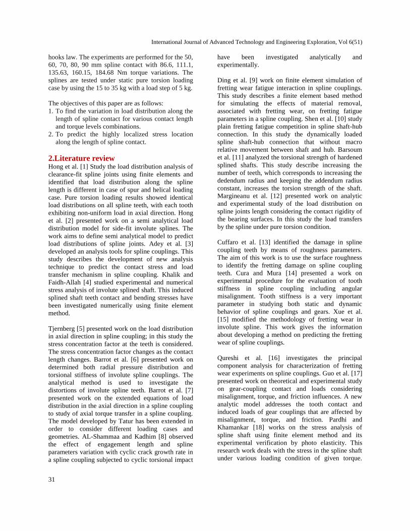
The average percentage error between experimental
and finite element analysis for 111.1 Nm torque is
8.03%. The comparison between the experimental
and finite element analysis for 111.1 Nm torque is
shown in Figure 18.
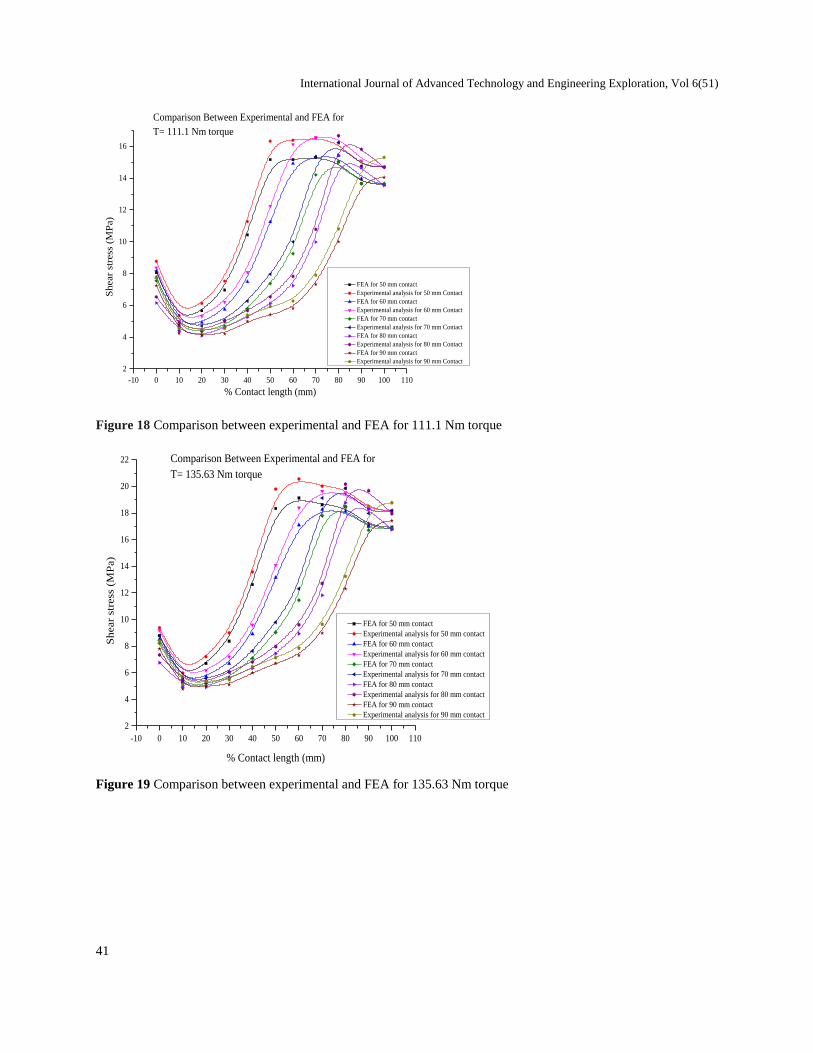
The average percentage error between experimental
and finite element analysis for 135.63 Nm torque is
7.50%. The comparison between the experimental
and finite element analysis for 135.63 Nm torque is
shown in Figure 19.
The average percentage error between experimental
and finite element analysis for 160.15 Nm torque is
7.80%. The comparison between the experimental
and finite element analysis for 160.15 Nm torque is
shown in Figure 20.
The average percentage error between experimental
and finite element analysis for 184.68 Nm torque is
7.65%. The comparison between the experimental
and finite element analysis for 184.68 Nm torque is
shown in Figure 21.
The comparison between the experimental and finite
element analysis is observed and the nature of the
stress variations along the length of contact is
observed. Because of the partial length of contact the
two zones are creating as contact and free zone. The
nature of the stress variation curve is upstream within
percentage length of contact (contact zone) and its
starts changing its nature to downstream in the free
zone.
-10 0 10 20 30 40 50 60 70 80 90 100 110
2
3
4
5
6
7
8
9
10
11
12
13
14
Shear
stre
ss (
MP
a)
% Contact Length (mm)
FEA for 50 mm contact
Experimental Analysis for 50 mm contact
FEA for 60 mm contact
Experimental Analysis for 60 mm contact
FEA for 70 mm contact
Experimental Analysis for 70 mm contact
FEA for 80 mm contact
Experimental Analysis for 80 mm contact
FEA for 90 mm contact
Experimental Analysis for 90 mm contact
Comparison Between Experimental and FEA for
T= 86.6 Nm torque
Figure 17 Comparison between experimental and FEA for 86.6 Nm torque
International Journal of Advanced Technology and Engineering Exploration, Vol 6(51)
41
-10 0 10 20 30 40 50 60 70 80 90 100 110
2
4
6
8
10
12
14
16
Sh
ear
stre
ss (
MP
a)
% Contact length (mm)
FEA for 50 mm contact
Experimental analysis for 50 mm Contact
FEA for 60 mm contact
Experimental analysis for 60 mm Contact
FEA for 70 mm contact
Experimental analysis for 70 mm Contact
FEA for 80 mm contact
Experimental analysis for 80 mm Contact
FEA for 90 mm contact
Experimental analysis for 90 mm Contact
Comparison Between Experimental and FEA for
T= 111.1 Nm torque
Figure 18 Comparison between experimental and FEA for 111.1 Nm torque
-10 0 10 20 30 40 50 60 70 80 90 100 110
2
4
6
8
10
12
14
16
18
20
22
Shear
stre
ss (
MP
a)
% Contact length (mm)
FEA for 50 mm contact
Experimental analysis for 50 mm contact
FEA for 60 mm contact
Experimental analysis for 60 mm contact
FEA for 70 mm contact
Experimental analysis for 70 mm contact
FEA for 80 mm contact
Experimental analysis for 80 mm contact
FEA for 90 mm contact
Experimental analysis for 90 mm contact
Comparison Between Experimental and FEA for
T= 135.63 Nm torque
Figure 19 Comparison between experimental and FEA for 135.63 Nm torque

Swapnil B. Patil and S. R. Patil
42
-10 0 10 20 30 40 50 60 70 80 90 100 110
2
4
6
8
10
12
14
16
18
20
22
24
26
Shear
stre
ss (
MP
a)
% Contact length(mm)
FEA for 50 mm contact
Experimental analysis for 50 mm contact
FEA for 60 mm contact
Experimental analysis for 60 mm contact
FEA for 70 mm contact
Experimental analysis for 70 mm contact
FEA for 80 mm contact
Experimental analysis for 80 mm contact
FEA for 90 mm contact
Experimental analysis for 90 mm contact
Comparison Between Experimental and FEA for
T= 160.15 Nm torque
Figure 20 Comparison between experimental and FEA for 160.15 Nm torque
-10 0 10 20 30 40 50 60 70 80 90 100 110
2
4
6
8
10
12
14
16
18
20
22
24
26
28
30
Sh
ear
stre
ss (
MP
a)
% Contact length (mm)
FEA for 50 mm contact
Experimental analysis for 50 mm contact
FEA for 60 mm contact
Experimental analysis for 60 mm contact
FEA for 70 mm contact
Experimental analysis for 70 mm contact
FEA for 80 mm contact
Experimental analysis for 80 mm contact
FEA for 90 mm contact
Experimental analysis for 90 mm contact
Comparison Between Experimental and FEA for
T= 184.68 Nm torque
Figure 21 Comparison between experimental and FEA for 184.68 Nm torque

International Journal of Advanced Technology and Engineering Exploration, Vol 6(51)
43
8.Conclusions and future scope For finding the load distribution three location is
defined as entry, mid and exit, and it is observed for
partial spline contact over a length, two zones are
created as contact zone and free zone.
The nature of the stresses in contact zone is
uniformly decreasing toward the free zone. The stress
at the contact zone is less as compare to free zone
because at the contact zone the reaction force is
generated by the hub pocket spline which neutral the
effect of active shear force which results to less stress
at contact zone.
The reaction force is not generating in free zone
because of the partial spline contact length which
results more stress at free zone as compare to contact
zone.
It is predicted that there is 10.81% average stress
reduction at the entry of spline. When the contact
length is increases, contact zone also increases. It
causes more spline profile area for shear stress
distribution which leads to reduction in stress at the
contact zone.
There is 64.60% average reduction is stress at the
midpoint of spline. For contact more than 60 mm the
midpoint lies in the contact zone, at midpoint the
surface area available for shear force is more which
leads to more percentage reduction in stress at this
location.
The highly localized stress is identified in free zone
probably at the end of percentage length of contact
and this stresses uniformly decreasing toward the
shoulder of spline shaft. There is negligible change
observed at the exit of the spline for all analysis
steps.
The nature of stress variation is same for all case
taken under study and it is observed that the nature of
curve for stress variation in contact zone is
downstream and stress variation cure is upstream in
free zone.
The stress at the end of contact is high because at the
end of contact the spline profile is unsupported and
experience a more torsion angle which leads to
failure of spline at this location.
In future this work can be extended to find the load
distribution in radial direction of spline, to find the
load variations in radial direction an experimental set
can be developed also the vibration analysis can be
done in dynamic state for the different contact length
of spline and load conditions.
Acknowledgment None.
Conflicts of interest The authors have no conflicts of interest to declare.
References [1] Hong J, Talbot D, Kahraman A. Load distribution
analysis of clearance-fit spline joints using finite
elements. Mechanism and Machine Theory. 2014;
74:42-57.
[2] Hong J, Talbot D, Kahraman A. A semi-analytical
load distribution model for side-fit involute splines.
Mechanism and Machine Theory. 2014; 76:39-55.
[3] Adey RA, Baynham J, Taylor JW. Development of
analysis tools for spline couplings. Proceedings of the
Institution of Mechanical Engineers, Part G: Journal of
Aerospace Engineering. 2000; 214(6):347-57.
[4] Khalik ZA, Faidh-Allah MH. Experimental and
numerical stress analysis of involute splined shaft.
Journal of Engineering. 2012; 18(4):415-22.
[5] Tjernberg A. Load distribution in the axial direction in
a spline coupling. Engineering Failure Analysis. 2001;
8(6):557-70.
[6] Barrot A, Paredes M, Sartor M. Determining both
radial pressure distribution and torsional stiffness of
involute spline couplings. Proceedings of the
Institution of Mechanical Engineers, Part C: Journal of
Mechanical Engineering Science. 2006; 220(12):1727-
38.
[7] Barrot A, Paredes M, Sartor M. Extended equations of
load distribution in the axial direction in a spline
coupling. Engineering Failure Analysis. 2009;
16(1):200-11.
[8] AL-Shammaa FA, Kadhim HF. An analysis of stress
distribution in a spline shaft subjected to cycilc
impulsive load. Journal of Engineering. 2014;
20(7):146-57.
[9] Ding J, Leen SB, Williams EJ, Shipway PH. Finite
element simulation of fretting wear-fatigue interaction
in spline couplings. Tribology-Materials, Surfaces &
Interfaces. 2008; 2(1):10-24.
[10] Shen LJ, Lohrengel A, Schäfer G. Plain–fretting
fatigue competition and prediction in spline shaft-hub
connection. International Journal of Fatigue. 2013;
52:68-81.
[11] Barsoum I, Khan F, Barsoum Z. Analysis of the
torsional strength of hardened splined shafts. Materials
& Design (1980-2015). 2014; 54:130-6.
[12] Mărgineanu D, Mărgineanu E, Zăbavă ES, Fârtă AM.
Analytic and experimental study of the load
distribution on spline joints length considering the
contact rigidity of the bearing surfaces. In Applied
Mechanics and Materials 2012 (pp. 74-83). Trans
Tech Publications.
Swapnil B. Patil and S. R. Patil
44
[13] Cuffaro V, Curà F, Mura A. Damage identification on
spline coupling teeth by means of roughness
parameters. Theoretical and Applied Fracture
Mechanics. 2016; 82:9-16.
[14] Cura F, Mura A. Experimental procedure for the
evaluation of tooth stiffness in spline coupling
including angular misalignment. Mechanical Systems
and Signal Processing. 2013; 40(2):545-55.
[15] Xue X, Wang S, Li B. Modification methodology of
fretting wear in involute spline. Wear. 2016; 368:435-
44.
[16] Qureshi W, Cura F, Mura A. Principal component
analysis for characterization of fretting wear
experiments on spline couplings. Procedia
Engineering. 2015; 109:73-9.
[17] Guo Y, Lambert S, Wallen R, Errichello R, Keller J.
Theoretical and experimental study on gear-coupling
contact and loads considering misalignment, torque,
and friction influences. Mechanism and Machine
Theory. 2016; 98:242-62.
[18] Pardhi DG, Khamankar SD. Stress analysis of spline
shaft using finite element method and its experimental
verification by photo elasticity. International Journal
of Mechanical Engineering and Robotics Research.
2014; 3(4):451-8.
Mr. Swapnil B. Patil is currently
pursuing his Masters of Engineering
from AISSMS COE, Pune. He
completed his B.E in Mechanical
Engineering from JTM COE, Faizpur
from North Maharashtra University,
Jalgaon.
Email: [email protected]
Mr. S. R. Patil is currently working as
Assistant Professor in AISSMS COE,
Pune. He is pursuing his PhD in
Mechanical Engineering in research
area of NVH. He completed Masters of
Engineering in Mechanical with
specialization in Design Engineering
and B.E. in Mechanical Engineering
from Pune University.