experimental and numerical analysis on behaviour of externally bonded rc t beams using gfrp...
DESCRIPTION
paperTRANSCRIPT

EXPERIMENTAL AND NUMERICAL STUDY ON BEHAVIOR
OF EXTERNALLY BONDED RC T-BEAMS
USING GFRP COMPOSITES
A THESIS SUBMITTED IN PARTIAL FULFILMENT
OF THE REQUIREMENTS FOR THE DEGREE OF
Master of Technology
In
Structural Engineering
By
TRISHANU SHIT
Roll. No. 209CE2049
DEPARTMENT OF CIVIL ENGINEERING
NATIONAL INSTITUTE OF TECHNOLOGY
ROURKELA, ORISSA
2011

EXPERIMENTAL AND NUMERICAL STUDY ON BEHAVIOR
OF EXTERNALLY BONDED RC T-BEAMS
USING GFRP COMPOSITES
A THESIS SUBMITTED IN PARTIAL FULFILMENT
OF THE REQUIREMENTS FOR THE DEGREE OF
Master of Technology
In
Structural Engineering
By
TRISHANU SHIT
Under the guidance of
Prof. K. C. BISWAL
DEPARTMENT OF CIVIL ENGINEERING
NATIONAL INSTITUTE OF TECHNOLOGY
ROURKELA, ORISSA
2011

NATIONAL INSTITUTE OF TECHNOLOGY ROURKELA
CERTIFICATE
This is to certify that the thesis entitled, “EXPERIMENTAL AND NUMERICAL
STUDY ON BEHAVIOR OF EXTERNALLY BONDED RC T-BEAMS USING GFRP
COMPOSITES” submitted by Trishanu Shit in partial fulfillment of the
requirements for the award of Master of Technology Degree in Civil
Engineering with specialization in “Structural Engineering” at National
Institute of Technology, Rourkela is an authentic work carried out by him under
my supervision and guidance. To the best of my knowledge, the matter embodied
in this Project review report has not been submitted to any other university/
institute for award of any Degree or Diploma.
Date: 24th MAY 2011 Dr. K.C. Biswal
Dept. of Civil Engineering
National Institute of Technology,
Rourkela-769008

ACKNOWLEDGEMENT
I express my gratitude and sincere thanks to Prof. K. C. Biswal, for his guidance and
constant encouragement and support during the course of my work in the last one year. I truly
appreciate and value his esteemed guidance and encouragement from the beginning to the end
of this thesis, his knowledge and company at the time of crisis would be remembered lifelong.
My sincere thanks to Prof. M. Panda, Head of the Civil Engineering Department, and
Prof. A. Patel, Professor of Civil Engineering Department, National Institute of Technology
Rourkela, for their advice and providing necessary facility for my work.
I am also very thankful towards Prof. A.V.Asha, my faculty adviser and all faculty
members of Civil Engineering Department for their help and encouragement during the
project.
I am also thankful to Mr. S. K. Sethi, Mr. R. Lugun and Mr. Sushil and
administrative staff of this department for their timely help.
I also thank all my friends who have directly or indirectly helped me in my project
work and in the completion of this report.
Last but not least I would like to thank my parents, who taught me the value of hard
work by their own example. I would like to share this moment of happiness with my father
and mother. They rendered me enormous support during the whole tenure of my stay in NIT
Rourkela.
Trishanu Shit
M. Tech (Structural Engineering)
Department of Civil Engineering
National Institute of Technology
Rourkela-769008

I
CONTENTS
Page No.
ABSTRACT V
LIST OF FIGURES VI - VIII
LIST OF TABLES IX
CHAPTER -1
INTRODUCTION 1-5
1.1 General 1
1.2 Advantages And Disadvantages Of FRP 3
1.2.1 Advantages 3
1.2.2 Disadvantages 4
CHAPTER-2
REVIEW OF LITERATURE 6-15
2.1 Brief Review 6
2.2 Critical Observation From The Literature 15
2.3 Objective And Scope Of The Present Work 15

II
CHAPTER-3
EXPERIMENTAL STUDY 16-58
3.1 Materials 16
3.1.1 Concrete 16
3.1.2 Cement 16
3.1.3 Fine Aggregate 17
3.1.4 Coarse Aggregate 18
3.1.5 Material Testing Of Concrete 18
3.1.5.1 Testing Of Cement 18
3.1.5.2 Testing Of Fine Aggregate 19
3.1.5.3 Testing Of Coarse Aggregate 19
3.1.5.4 Mix Design Of M20 Grade Concrete 21
3.1.6 Reinforcement 22
3.1.6.1 Detailing Of Reinforcement in R.C. T- Beams 22
3.1.7 Fiber Reinforced Polymer (FRP) 24
3.1.7.1 Fiber 25
3.2 Experimental Study 27
3.3 Casting Of Specimen 27
3.3.1 Materials For Casting 27
3.3.1.1 Cement 27
3.3.1.2 Fine Aggregate 27
3.3.1.3 Coarse Aggregate 28
3.3.1.4 Water 28
3.3.1.5 Reinforcing Steel 28
3.3.2 Form Work 28
3.3.3 Mixing Of Concrete 28

III
3.3.4 Compaction 28
3.3.5 Curing Of Concrete 29
3.4 Strengthening Of Beams 29
3.5 Experimental Setup 31
3.5.1 Testing Of Beams 33
3.5.1.1 Beam.1- Control Beam 34
3.5.1.2 Beam.2 Single Layered GFRP Bonded At 37
Bottom of Web from End To End
3.5.1.3 Beam.3 Single Layered GFRP Bonded At 40
Bottom of Web from L/3 To 2l/3
3.5.1.4 Beam.4 U- Jacketed Single Layered GFRP 43
Bonded From End To End
3.5.1.5 Beam.5 U- Jacketed Single Layered GFRP 44
Bonded Only At the Mid Section
3.5.1.6 Beam.6 U- Jacketed Single Layered GFRP 50
Retrofitted On Cracked Beam At The Mid Section.
3.5.1.7 Beam.7 U- Jacketed Single Layered GFRP 54
Retrofitted On Cracked Beam From End To End.
CHAPTER -4
RESULTS AND DISCUSSIONS 58-89
4.1 Introduction 58
4.2 Failure Modes 58
4.3 Load Deflection Analysis 59
4.4 Ultimate Load Carrying Capacity 88

IV
CHAPTER 5
CONCLUSIONS 90-91
5.1 Conclusions 90
5.2 Scope of the Future Work 91
CHAPTER 6
REFERENCES 92-97

V
ABSTRACT
Fiber-reinforced polymer (FRP) application is a very effective way to repair and
strengthen structures that have become structurally weak over their life span. FRP repair
systems provide an economically viable alternative to traditional repair systems and materials.
In this study experimental investigation on the flexural behavior of RC T-beams strengthened
using glass fiber reinforced polymer (GFRP) sheets are carried out.
Reinforced concrete T beams externally bonded with GFRP sheets were tested to
failure using a symmetrical two point static loading system. Seven RC T-beams were casted
for this experimental test. All of them were weak in flexure and were having same
reinforcement detailing. One beam was used as a control beam and six beams were
strengthened using different configurations of glass fiber reinforced polymer (GFRP) sheets.
Experimental data on load, deflection and failure modes of each of the beams were obtained.
The effect of different amount and configuration of GFRP on ultimate load carrying capacity
and failure mode of the beams were investigated.
The experimental results show that externally bonded GFRP can increase the flexural
capacity of the beam significantly. In addition the results indicated that the most effective
configuration was the U-wrap GFRP .A series of comparative studies on deflection between
the present experimental data and results from finite element method and IS code method were
made. Future area of research are being outlined.

VI
LIST OF FIGURES
Figure No. Title Page No.
Fig: 3.1 Reinforcement Detailing of T- Beam 22
Fig: 3.2 Front View of Reinforcement Detailing of T- Beam 23
Fig: 3.3 3D View of Reinforcement Detailing of T- Beam 23
Fig: 3.4 Formation of Fiber Reinforced Polymer Composite 24
Fig: 3.5 Steel Frame Used For Casting of T-Beam 28
Fig: 3.6 Application of epoxy and hardener on the beam 30
Fig: 3.7 Fixing of GFRP sheets on the beam 30
Fig: 3.8 Roller used for the removal of air bubble 31
Fig: 3.9 point loading experimental setup 32
Fig: 3.10 Shear force and bending moment diagram for two point loading 32
Fig: 3.11 Experimental Setup 33
Fig: 3.12 Experimental Setup of the Control Beam 1 34
Fig: 3.13 Control Beam After Cracking 35
Fig: 3.14 Crack Pattern At 2l/3 (Near Right Support) 35
Fig: 3.15 Crack Pattern At L/2(At Center) 35
Fig: 3.16 Experimental Setup of Beam 2 37
Fig: 3.17 Debonding of Fiber 38
Fig: 3.18 Debonding cracks near the centre and under the loads 38
Fig: 3.19 Cracks under the load at L/3 38
Fig: 3.20 Cracks under the load at 2L/3 38
Fig: 3.21 Cracks in Beam 3 40
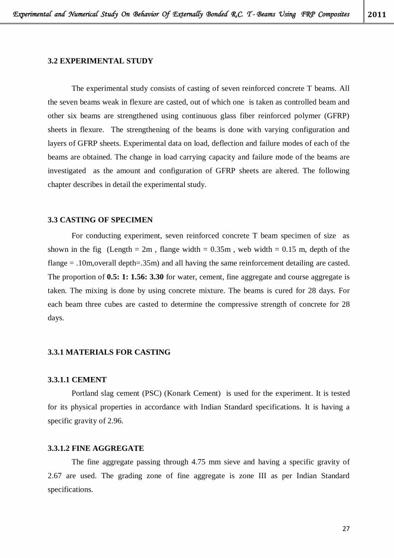
Fig: 3.22 Debonding of fiber at L/3 and 2L/3 41
Fig: 3.23 U-jacketed GFRP wrapped on the Beam 4 43

VII
Figure No. Title Page No.
Fig: 3.24 Beam 4 after testing 43
Fig: 3.25 Tearing of GFRP in Beam 4 at 300 KN 44
Fig: 3.26 Crack developed in Beam 4 under the GFRP 44
Fig: 3.27 Experimental Setup of the Beam 5 46
Fig:3.28 Beam 5 after testing 47
Fig:3.29 Tearing started at the mid section at 308 KN 47
Fig: 3.30 Total tearing of the fiber at the midsection 48
Fig: 3.31 Crack developed under GFRP in BEAM 5 48
Fig: 3.32 Crack formed after initial loading in Beam 6 50
Fig: 3.33 Magnified pictures of the hair line cracks formed during the initial 50
loading in Beam 6
Fig: 3.34 Retrofitted Beam 6 51
Fig: 3.35 Debonding of the Retrofitted Beam 6 51
Fig: 3.36 Crack pattern under the GFRP in Beam 6 51
Fig: 3.37 Crack patterns after initial loading in Beam 7 54
Fig: 3.38 Magnified picture of the crack patterns in Beam 7 54
Fig: 3.39 Retrofitted Beam 7 55
Fig: 3.40 Tearing of GFRP in Beam 7 55
Fig: 3.41 Cracks under GFRP in Beam 7 55
Fig: 4.1 Load vs. Deflection Curve for Control Beam 1 60
Fig: 4.2 Load vs. Deflection Curve for Beam 2 61
Fig: 4.3 Load vs. Deflection Curve for Beam 3 62
Fig: 4.4 Load vs. Deflection Curve for Beam 4 63

VIII
Figure No. Title Page No.
Fig :4.5 Load vs. Deflection Curve for Beam 5 64
Fig:4.6 Load vs. Deflection Curve for Beam 4 before retrofitting 65
Fig: 4.7 Load vs. Deflection Curve for Beam 6 after retrofitting 66
Fig: 4.8 Load vs. Deflection Curve for Beam 6 before and after retrofitting 67
Fig: 4.9 Load vs. Deflection Curve for Beam 7 before retrofitting 68
Fig: 4.10 Load vs. Deflection Curve for Beam 7 after retrofitting 69
Fig: 4.11 Load vs. Deflection Curve for Beam 6 before and after retrofitting 70
Fig: 4.12 Load vs. Deflection Curve for Beam 1 and 2 71
Fig: 4.13 Load vs. Deflection Curve for Beam 1 and Beam 3 72
Fig: 4.14 Load vs. Deflection Curve for Beam 1 and Beam 4 73
Fig: 4.15 Load vs. Deflection Curve for Beam 1 and Beam 5 74
Fig: 4.16 Load vs. Deflection Curve for Beam 1 and Beam 6 75
Fig: 4.17 Load vs. Deflection Curve for Beam 1 and Beam 7 76
Fig: 4.18 Load vs. Deflection Curve for Beam 2 and Beam 3 77
Fig: 4.19 Load vs. Deflection Curve for Beam 4 and Beam 5 78
Fig: 4.20 Load vs. Deflection Curve for Beam 1, 2, 3, 4 and Beam 5 79
Fig: 4.21 Load vs. Deflection Curve for Beam 6 and Beam 7 80
Fig: 4.22 Load vs. Deflection Curve for all the Beams 81
Fig: 4.23 Load vs. Deflection Curve for Beam 5 and Beam 6 82
Fig: 4.24 Load vs. Deflection Curve for Beam 4 and Beam 7 83
Fig: 4.25 Load vs. Deflection for Control Beam 1 using different methods 85
Fig: 4.26 Load vs. Deflection Curve for Beam 2 using different methods 87
Fig: 4.27 Ultimate Load carrying capacity 88
Fig: 4.28 Percentage increase in the Ultimate Carrying capacity 89

IX
LIST OF TABLES
Table No. Title Page No.
Table 3.1 Results of Sieve Analysis for Fine Aggregate 19
Table 3.2 Results of Sieve Analysis for Coarse Aggregate (20mm) 20
Table 3.3 Results of Sieve Analysis for Coarse Aggregate (10mm) 20
Table 3.4 Results of Sieve Analysis for Coarse Aggregate (10mm) 21
Table 3.5 Properties of different fibers 25
Table 3.6 Typical composition of fiberglass (% in weight) 26
Table 3.7 Deflection Values of Control Beam1 36
Table 3.8 Deflection Values of Beam 2 39
Table 3.9 Deflection Values of Beam 3 42
Table 3.10 Deflection values of Beam 4 45
Table 3.11 Deflection values of Beam 5 49
Table 3.12 Deflection of Beam 6 (before retrofitting) 52
Table 3.13 Deflection of Beam 6 (after retrofitting) 53
Table 3.14 Deflection of Beam.7(before retrofitting) 56
Table 3.15 Deflection of Beam.7(after retrofitting) 57
Table 4.1 Deflection of Control Beam 1 from different methods 84
Table 4.2 Deflection of Beam 2 from different methods 86

Experimental and Numerical Study On Behavior Of Externally Bonded R.C. T - Beams Using FRP Composites 2011
1
CHAPTER -1
INTRODUCTION
1.1 GENERAL
Deterioration in concrete structures is a major challenge faced by the infrastructure and
bridge industries worldwide. The deterioration is mainly due to environmental effects, which
includes corrosion of steel, gradual loss of strength with ageing, repeated high intensity
loading, variation in temperature, freeze-thaw cycles, contact with chemicals and saline water
and exposure to ultra-violet radiations. This problem, coupled with revisions in structural
codes needed to account for the natural phenomena like earthquakes or environmental
deteriorating forces, demands development of successful structural retrofit technologies. The
structural retrofit problem has two options, repair/retrofit or demolition/reconstruction.
Traditionally, the trend within the US construction industries has been towards the latter
option. This solution has become increasingly unacceptable due to changing economic and
social attitudes concerning existing structures. This fact leads to the necessity for development
of appropriate structural retrofit/repair systems.
Traditionally, the retrofitting of reinforced concrete structures, such as columns, beams
and other structural elements, involved a time consuming and disruptive process of removing
and replacing the low quality or damaged concrete or/and steel reinforcements with new and
stronger material. However, with the introduction of new advanced composite materials such
as fiber reinforced polymer (FRP) composites, concrete members can now be easily and
effectively strengthened using externally bonded FRP composites.
Retrofitting of concrete structures with wrapping FRP sheets provide a more
economical and technically superior alternative to the traditional techniques in many situations
because it offers high strength, low weight, corrosion resistance, high fatigue resistance, easy
and rapid installation and minimal change in structural geometry. In addition, FRP
manufacturing offers a unique opportunity for the development of shapes and forms that
would be difficult or impossible with the conventional steel materials. Although the fibers and
resins used in FRP systems are relatively expensive compared with traditional strengthening
materials, labor and equipment costs to install FRP systems are often lower. FRP systems can
also be used in areas with limited access where traditional techniques would be impractical.

Experimental and Numerical Study On Behavior Of Externally Bonded R.C. T - Beams Using FRP Composites 2011
2
However, the use of these materials for retrofitting the existing concrete structures cannot
reach up to the expectation due to lack of the proper knowledge on structural behavior of
concrete structures retrofitted by fiber reinforced polymers (FRP) composites. Successful
retrofitting of concrete structures with FRP needs a thorough knowledge on the subject and
available user-friendly technologies/ unique guidelines.
Beams are the critical structural members subjected to bending, torsion and shear in all
type of structures. Similarly, columns are also used as various important elements subjected to
axial load combined with/without bending and are used in all type of structures considering
from building to bridge as piers or abutments. Therefore, extensive research works are being
carried out throughout world on retrofitting of concrete beams and columns with externally
bonded FRP composites. Several investigators took up concrete beams and columns retrofitted
with carbon fiber reinforced polymer (CFRP)/ glass fiber reinforced polymer (GFRP)
composites in order to study the enhancement of strength and ductility, durability, effect of
confinement, preparation of design guidelines and experimental investigations of these
members. The results obtained from different investigations regarding enhancement in basic
parameters like strength/stiffness, ductility and durability of structural members retrofitted
with externally bonded FRP composites, though quite encouraging, still suffers from many
limitations. This needs further study in order to arrive at recognizing FRP composites as a
potential full proof structural additive.
FRP repair is a simple way to increase both the strength and design life of a structure.
Because of its high strength to weight ratio and resistance to corrosion, this repair method is
ideal for deteriorated concrete structure due to exposure to de-icing salts and other
environmental factors by encasing concrete members .FRP protects from existing salts and
other environmental factors .It is noted that in many bridges the majority of corrosive damage
occurred on exterior girders. This indicates that deleterious effects may be direct results of
surface exposure, to spray of water, de-icing agents and environmental effects. Encasement of
these girders not only increases design life, but also protects the members from surface
attacks.FRP is a versatile material.
FRP can be applied to wide range of structures. FRP sheet can be cut and easily
bonded to any concrete members. It is highly cost effect method of maintaining or upgrading
existing structures. Quick application results in lower disruption and shorter contact periods.
Reasons for strengthening of structures may include upgrading to accommodate higher loads

Experimental and Numerical Study On Behavior Of Externally Bonded R.C. T - Beams Using FRP Composites 2011
3
(such as traffics), loss of pre-stress in existing reinforcement, or degradation of structures (e.g.
corrosion of reinforcement).
The technique may allow continued usage of structures or facility during strengthening
works. Higher material cost of Carbon /Glass fiber is outweighed by numerous advantages
over steel such as low self-weight and less requirement for plate surface preparation. Glass or
Aramid fibers offer lower cost alternative, in some instances, to carbon fibers.
FRP plates are an alternative to other forms of strengthening such as use of steel plates,
or provision of additional support members. Column wrapping with FRP can be an alternative
to jacketing additional reinforced concrete, or complete replacement of structures, with
obvious saving in materials energy.
It increases the capacity with minimal addition of dead load to the structure. Materials
are easy to transport and handle no lifting gear required. It is easy to use at height. It increases
the ability to work in confined areas and in situations with difficult access (e.g. tunnel and
basements). This technique is relatively quick with reduced disturbance and installation time.
1.2 ADVANTAGES AND DISADVANTAGES OF FRP
1.2.1 ADVANTAGES
FRP materials have higher ultimate strength and lower density as compared to steel.
When these properties are taken together they lead to fiber composites having a
strength/weight ratio higher than steel plate in some cases. The lower weight of FRP makes
installation and handling significantly easier than steel. These properties are particularly
important when installation is done in cramped locations. Other works like works on soffits of
bridges and building floor slabs are carried out from man-access platforms rather than from
full scaffolding. We all know that steel plate requires heavy lifting gear and are to be held in
place while the adhesive gains its strength and bolts are fitted through the steel plate into the
parent concrete to support the plate while the adhesive cures.
On the other hand, the application of FRP plate or sheet material is like applying
wallpaper; once it has been rolled on carefully to remove entrapped air and excess adhesive it
may be left unsupported. Here, no bolts are required; in fact, the use of bolts would seriously
weaken the material unless additional cover plates are bonded on. Furthermore, because there

Experimental and Numerical Study On Behavior Of Externally Bonded R.C. T - Beams Using FRP Composites 2011
4
is no need to drill into the structure to fix bolts or other mechanical anchors there is no risk of
damaging the existing reinforcement. Fiber composite materials are available in very long
lengths while steel plate is generally limited to 6 m. The availability of long lengths and the
flexibility of the material also simplify installation:
• Laps and joints are not required
• The material can take up irregularities in the shape of the concrete surface
• The material can follow a curved profile; steel plate would have to be pre-bent to the
required radius.
• The material can be readily installed behind existing services
• Overlapping, required when strengthening in two directions, is not a problem because the
material is thin.
The materials fibers and resins are durable if correctly specified, and require little
maintenance. If they are damaged in service, it is relatively simple to repair them, by adding
an additional layer. The use of fiber composites does not significantly increase the weight of
the structure or the dimensions of the member. The latter may be particularly important for
bridges and other structures with limited headroom and for tunnels. In terms of environmental
impact and sustainability, studies have shown that the energy required to produce FRP
materials is less than that for conventional materials. Because of their light weight, the
transport of FRP materials has minimal environmental impact.
These various factors in combination lead to a significantly simpler and quicker
strengthening process than when using steel plate. This is particularly important for bridges
because of the high costs of lane closures and possession times on major highways and
railway lines. It has been estimated that about 90% of the market for plate strengthening in
Switzerland has been taken by carbon plate systems as a result of these factors.
1.2.2 DISADVANTAGES
The main disadvantage of externally strengthening structures with fiber composite
materials is the risk of fire, vandalism or accidental damage, unless the strengthening is
protected. A particular concern for bridges over roads is the risk of soffit reinforcement being
hit by over-height vehicles. However, strengthening using plates is generally provided to carry
additional live load and the ability of the unstrengthened structure to carry its own self-weight
is unimpaired. Damage to the plate strengthening material only reduces the overall factor of
safety and is unlikely to lead to collapse. Experience of the long-term durability of fiber

Experimental and Numerical Study On Behavior Of Externally Bonded R.C. T - Beams Using FRP Composites 2011
5
composites is not yet available. This may be a disadvantage for structures for which a very
long design life is required but can be overcome by appropriate monitoring.
A perceived disadvantage of using FRP for strengthening is the relatively high cost of
the materials. However, comparisons should be made on the basis of the complete
strengthening exercise; in certain cases the costs can be less than that of steel plate bonding. A
disadvantage in the eyes of many clients will be the lack of experience of the techniques and
suitably qualified staff to carry out the work. Finally, a significant disadvantage is the lack of
accepted design standards.

Experimental and Numerical Study On Behavior Of Externally Bonded R.C. T - Beams Using FRP Composites 2011
6
CHAPTER-2
REVIEW OF LITERATURE
2.1 BRIEF REVIEW
Development of FRP materials in various forms and configurations offers an
alternative design approach for construction of new structures and rehabilitation of the
existing structures. Research on FRP material for use in concrete structures began in Europe in
the mid 1950’s [Rubinsky and Rubinsky, 1954; Wines, J. C. et al., 1966]. The pioneering
work of bonded FRP system can be credited to Meier [Meier 1987]; this work led to the first
on-site repair by bonded FRP in Switzerland [Meier and Kaiser 1991].Japan developed its first
FRP applications for repair of concrete chimneys in the early 1980s [ACI 440 1996].By 1997
more than 1500 concrete structures worldwide had been strengthened with externally bonded
FRP materials. Thereafter, many FRP materials with different types of fibres have been
developed. FRP products can take the form of bars, cables, 2-D and 3-D grids, sheet materials
and laminates.
Though the research and application of retrofitting/strengthening of concrete structures
using externally bonded FRP composites has started recently, i.e., about few decades ago, it is
rapidly gaining the momentum in attracting the research communities and construction
industries. The Naval Facilities Engineering Service Center (NFESC) started a project in the
early 1990’s to explore the use of composite materials for repairing or strengthening
waterfront structures under sponsorship by the office of Naval Research (Odello, 2001).
During that time the Navy teamed with the Army Corps of Engineers, presently known as the
Market Development Alliance (MDA) of the FRP Composites Industry on a project for the
Construction of Productive Advancement Research (CPAR) program. The program involved
testing of fender piles fabricated with FRP materials. The piles having FRP casing around a
concrete core showed very good stiffness and strength properties under bending loads (Hoy et
al., 1996; Hoy, 1996). Research investigations that deal with the strengthening of structures
using carbon fibre reinforced polymer (CFRP) sheets/strips/plates are conducted by many
investigators (Saadtmanesh and Ehsani, 1990 & 1991; Meier et al., 1992; Chajes et al., 1994;

Experimental and Numerical Study On Behavior Of Externally Bonded R.C. T - Beams Using FRP Composites 2011
7
Grace et al., 1999). In these investigations, they are primarily interested to examine the
increase in load carrying capacity of the flexural members.
Nanni et al. (1997) made analytical & experimental study of the retrofitting effect of
CFRP sheets applied on the tension side & web of the damaged R.C. beams due to loading
beyond cracking strength of concrete. Besides, the effect of CFRP sheets on stiffening effect is
studied with various orientations of fibres with respect to beam axis. Results showed a
substantial enhancement in the strength of the retrofitted damaged beams varying from 20%
to 60%. Malek et al. (1998) also carried out an experimental investigation to predict the
failure load of RC beams strengthened with FRP plates. Their experimental study showed
local failure of the concrete cover along the longitudinal reinforcement in the retrofitted beams
due to stress concentration of the plate end. Grace et al. (1999) investigated the behaviour of
RC beams strengthened with CFRP and GFRP sheets and laminates. They studied the
influence of the number of layers, epoxy types, and strengthening pattern on the response of
the beams. It is observed that all beams experienced brittle failure, with appreciable
enhancement in strength, thus requiring a higher factor of safety in design.
Experimental investigations, theoretical calculations and numerical simulations
showed that strengthening the reinforced concrete beams with externally bonded CFRP sheets
in the tension zone considerably increased the strength at bending, reduced deflections as well
as cracks width (Ross et al., 1999; Sebastian, 2001; Smith & Teng, 2002; Yang et al., 2003;
Aiello & Ombres, 2004). It also changed the behaviour of these beams under load and failure
pattern. Most often the strengthened beams failed in a brittle way, mainly due to the loss of
connection between the composite material and the concrete. Chajes et al. (1996) conducted
an experimental study to understand the nature of the bond between the composite plates and
concrete.
The influence of the surface preparation of the concrete, adhesive type, and concrete
strength on the overall bond strength is studied as well as characteristics of force transfer from
the plate to concrete. They concluded that the surface preparation along with along with
soundness of concrete could influence the ultimate bond strength. Thereafter, Study on de-
bonding problems in concrete beams externally strengthened with FRP composites are carried
out by many researchers.

Experimental and Numerical Study On Behavior Of Externally Bonded R.C. T - Beams Using FRP Composites 2011
8
Many investigators used externally bonded FRP composites to improve the flexural
strength of reinforced concrete members. To evaluate the flexural performance of the
strengthened members, it is necessary to study flexural stiffness of FRP strengthened members
at different stages, such as pre-cracking, post-cracking and post-yielding. However, only few
studied are focused on the reinforced concrete members strengthened under pre-loading or
pre-cracking (Arduni & Nanni, 1997).
Several investigators (Saadatmanesh et al., 1994; Shahawy, 2000) took up FRP
strengthened circular or rectangular columns studying enhancement of strength and ductility,
durability, effect of confinement, preparation of design guidelines and experimental
investigations of these columns. Saadatmanesh et al. (1994) studied the strength and ductility
of concrete columns externally reinforced with fibre composite strap. Chaallal and Shahawy
(2000) reported the experimental investigation of fiber reinforced polymer-wrapped reinforced
concrete column under combined axial-flexural loading.
Martinez et al (2008) described a procedure, based on a finite element formulation that
can be used to perform numerical simulations of RC structures reinforced with FRP.
Rajamohan et al (2009) studied the effect of inclined GFRP strips epoxy bonded to the beam
web for shear strengthening of reinforced concrete beams. He also studied the effectiveness in
terms of width and spacing of inclined GFRP strips, spacing of internal steel stirrups, and
longitudinal steel rebar section on shear capacity of the RC beam study to investigate the
behaviour of structurally damaged full-scale reinforced concrete beams retrofitted with CFRP
laminates in shear or in flexure. Obaidat et al (2010) studied the Retrofitting of reinforced
concrete beams using composite laminates and the main variables considered are the internal
reinforcement ratio, position of retrofitting and the length of CFRP.
The experimental results, indicated that beams retrofitted in shear and flexure by using
CFRP laminates are structurally efficient and are restored to stiffness and strength values
nearly equal to or greater than those of the control beams Tanarslan et al (2009) analyzed the
behavior and failure modes of T-section RC beams strengthened in shear with externally
bonded CFRP strips and the test results confirmed that all CFRP arrangements differ from
CFRP strip width and arrangement, improved the strength and behavior of the specimens in
different level significantly. Nanni et al (2000) studied the shear performance of reinforced
concrete (RC) beams with T-section. Different configurations of externally bonded carbon
fiber-reinforced polymer (CFRP) sheets are used to strengthen the specimens in shear. the

Experimental and Numerical Study On Behavior Of Externally Bonded R.C. T - Beams Using FRP Composites 2011
9
result showed that externally bonded CFRP can increase the shear capacity of the beam
significantly. In addition it indicated that the most effective configuration is the U-wrap with
end anchorage.
Though several researchers have been engaged in the investigation of the strengthened
concrete structures with externally bonded FRP sheets/laminates/fabrics, no country yet has
national design code on design guidelines for the concrete structures retrofitted using FRP
composites. However, several national guidelines (The Concrete Society, UK:2004; ACI
440:2002; FIB:2001; ISIS Canada:2001; JBDPA:1999) offer the state of the art in selection of
FRP systems and design and detailing of structures incorporating FRP reinforcement. On the
contrary, there exists a divergence of opinion about certain aspects of the design and detailing
guidelines. This is to be expected as the use of the relatively new material develops
worldwide. Much research is being carried out at institutions around the world and it is
expected that design criteria will continue to be enhanced as the results of this research
become know in the coming years.
Structural adhesives are generally accepted to be monomer composites which
polymerize to give fairly stiff and strong adhesive uniting relatively rigid adherents to form a
load-bearing joint (Shields, 1985). The feasibility of bonding concrete with epoxy resins is
first demonstrated in the late 1940s (ACI, 1973), and the early development of structural
adhesives is recorded by Fleming and King (1967). Since the early 1950s adhesives have
become widely used in civil engineering (Mays, 1985). However, although the building and
construction industries represent some of the largest users of adhesive materials, many
applications are non-structural in the sense that the bonded assemblies are not used to transmit
or sustain significant stresses (e.g. crack injection and sealing, skid-resistant layers, bonding
new concrete to old). Truly structural application implies that the adhesive is used to provide a
shear connection between similar or dissimilar materials, enabling the components being
bonded to act as a composite structural unit.
A comprehensive review of applications involving the use of adhesives in civil
engineering is given by Hewlett and Shaw (1977), Tabor (1982) and Mays and Hutchinson
(1992). Assessment of an adhesive as a suitable product for structural use must take into
account the design spectrum of loads, the strength and stiffness of the material under short

Experimental and Numerical Study On Behavior Of Externally Bonded R.C. T - Beams Using FRP Composites 2011
10
term, sustained or cyclic loads and the effect on these properties of temperature, moisture and
other environmental conditions during service (Mays, 1993). Concern regarding the durability
properties of adhesive joints has meant that resistance to creep, fatigue and fracture are
considered of greater importance than particularly high strength (Vardy and Hutchinson,
1986). Temperature is important at all stages in the use and performance of adhesives,
affecting viscosity and therefore workability, usable life and contact time, rate of cure, degree
of cross-linking and final cured performance (Tu and Kruger, 1996).
Controlled conditions are therefore generally required during bonding. This applies
equally during the surface treatment procedures if a durable system is to be achieved.
Adhesives, which are workable and cure at ambient temperatures, have been used and are able
to tolerate a certain amount of moisture without a marked reduction in performance. These
must have adequate usable time under site conditions and a cure rate which does not hinder
the construction program. Workmanship under conditions prevalent on site is less conducive
to quality control than in other industries, and thus ability to tolerate minor variations in
proportioning and mixing, as well as imperfect surface treatment, is important. In addition, the
products involved are more toxic, require more careful storage and, bulk for bulk, are
considerably more expensive than traditional construction materials. Nondestructive test
methods for assessing the integrity of bonded joints are now available for civil engineering
applications. Despite some drawbacks, structural adhesives have enormous potential in future
construction applications, particularly where the combination of thick bondlines, ambient
temperature curing and the need to unite dissimilar materials with a relatively high strength
joint are important (Mays and Hutchinson, 1992).
The principal structural adhesives specifically formulated for use in the construction
Industry are epoxy and unsaturated polyester resin systems, both thermosetting polymers. The
formulation of adhesives is considered in detail by Wake (1982), whilst Tabor (1978) offers
guidance on the effective use of epoxy and polyester resins for civil engineering structures.
Two-part epoxies, first developed in the 1940s (Lee and Neville, 1967), consist of a resin, a
hardener or cross-linking agent which causes polymerization, and various additives such as
fillers, tougheners or flexibilisers, all of which contribute to the physical and mechanical
properties of the resulting adhesive. Formulations can be varied to allow curing at ambient
temperature, the so-called cold cure epoxies, the most common hardeners for which are
aliphatic polyamines, whose use results in hardened adhesives which are rigid and provide
good resistance to chemicals, solvents and water (Mays and Hutchinson, 1992). Correct
proportioning and thorough mixing are imperative when using epoxy resin systems. The rate

Experimental and Numerical Study On Behavior Of Externally Bonded R.C. T - Beams Using FRP Composites 2011
11
of curing doubles as the temperature increases by 10°C and halves as the temperature drops by
10 °C and many of the formulations stop curing altogether below a temperature of 5 °C.
Fillers, generally inert materials such as sand or silica, may be used to reduce cost, creep and
shrinkage, reduce exotherm and the coefficient of thermal expansion, and assist corrosion
inhibition and fire retardation. Fillers increase the viscosity of the freshly mixed system but
impart thixotropy, which is useful in application to vertical surfaces.
Unmodified epoxy systems tend to be brittle when cleavage or peel forces are
imposed. Toughening of the cured adhesive can be achieved by the inclusion of a dispersed
rubbery phase which absorbs energy and prevents crack propagation. Epoxies are generally
tolerant of many surface and environmental conditions and possess relatively high strength.
They are preferred for bonding to concrete since, of all adhesives, they have a particularly
high tolerance of the alkalinity of concrete, as well as moisture. By suitable formulation, their
ability to wet out the substrate surfaces can even be achieved in the presence of water, the
resin being able to disperse the water from the surface being bonded (Tabor, 1978).
Unsaturated polyester resins are discovered in the mid-1930s and have adhesive properties
obtained by cross-linking using a curing agent. They are chemically much more simple than
epoxy resins but have a 10% contraction by volume during curing due to a volume change
during the transition from the uncured liquid phase to the hardened resin resulting in further
curing shrinkage. As a result of these factors, there are usually strict limits on the volume of
material that can be mixed and applied at any one time and as a general rule polyester resins
do not form as strong adhesive bonds as do epoxy resins. In storage, the polyester resins are
also somewhat less stable and present a greater fire hazard than epoxies. These limitations
significantly restrict their applications.
The advantages of epoxy resins over other polymers as adhesive agents for civil
Engineering use can be summarized as follows (Mays and Hutchinson, 1992):
High surface activity and good wetting properties for a variety of substrates.
May be formulated to have a long open time (the time between mixing and closing of
the joint).
High cured cohesive strength, so the joint failure may be dictated by the adherend
strength, particularly with concrete substrates.
May be toughened by the inclusion of a dispersed rubbery phase.
Minimal shrinkage on curing, reducing bond line strain and allowing the bonding of
large areas with only contact pressure.

Experimental and Numerical Study On Behavior Of Externally Bonded R.C. T - Beams Using FRP Composites 2011
12
Low creep and superior strength retention under sustained load. Can be thixotropic for
application to vertical surfaces.
Able to accommodate irregular or thick bond lines.
Formulation can be readily modified by blending with a variety of materials to
achieve desirable properties.
These various modifications make epoxy adhesives relatively expensive in comparison to
other adhesives. However, the toughness, range of viscosity and curing conditions, good
handling characteristics, high adhesive strength, inertness, low shrinkage and resistance to
chemicals have meant that epoxy adhesives have found many applications in construction, for
example, repair materials, coatings and as structural and non-structural adhesives.
There are many features of an adhesive product, in addition to its purely adhesive
properties, which will form the basis for the selection of a particular bonding system. Mays
(1985) has considered requirements for adhesives to be used for external plate bonding to
bridges under conditions prevalent in the UK. These requirements are extended and refined in
a later publication referred to as a proposed Compliance Spectrum (Mays and Hutchinson,
1988), which addresses the general engineering requirements of adhesives, bonding
procedures and test methods for structural steel-to-concrete bonding, based on research work
at the University of Dundee (Hutchinson, 1986). The requirements proposed for the adhesive
itself can be considered to be equally applicable to fiber reinforced polymer (FRP) plate
bonding. An epoxy resin and polyamine hardener is recommended. Choice of a suitable
adhesive is only one of a number of requirements for a successfully bonded joint. Other
factors also affect the joint strength and performance (Maysand Hutchinson, 1988) namely:
appropriate design of the joint
adequate preparation of the adherend surfaces
controlled fabrication of the joint
protection from unacceptably hostile conditions in service
Post bonding quality assurance.
Both short term and long term structural performance are likely to be improved by
using an appropriately designed joint and suitably preparing the surface of the substrate
materials. A review of factors important to the satisfactory design of joints is given by Adams
and Wake (1984) and Lees (1985) and will not be considered here. Full account must be taken
of the poor resistance of adhesives to peel and cleavage forces; shear strength itself is unlikely
to be a limiting factor. With concrete structures, the tensile/shear, or tear-off strength of the

Experimental and Numerical Study On Behavior Of Externally Bonded R.C. T - Beams Using FRP Composites 2011
13
concrete should be the critical design factor if a suitable adhesive formulation is selected and
appropriate methods of surface preparation implemented. This has been demonstrated through
detailed shear testing on site and in the laboratory (Moustafa, 1974; Hugenschmidt, 1975;
Schultz, 1976). A number of tests are available for testing adhesive and thin films (Adams and
Wake, 1984; Kinloch, 1987). However, appropriate tests for assessing bond strength in
construction are complicated by the fact that the loading condition in service is difficult to
simulate, and one of the adherends, namely concrete, tends to be weaker in tension and shear
than the adhesives which may be used, making discrimination between adhesive systems
difficult. As a result, confirmation of the suitability of a proposed adhesive system is generally
limited to demonstrating that, when the bond line is stressed in the test configuration chosen,
the failure surface occurs within the concrete substrate. Such tests may also be used to exhibit
the adequacy of the surface preparation techniques employed, since it is difficult to separate
the individual effects on adhesion of the adhesive type and method of surface treatment
.
Several possible test methods have evolved to measure the bond strength between
adhesive and concrete substrates, mainly for applications in concrete repair (Franke, 1986;
Naderi et al., 1986). The Réunion Internationale des Laboratoires d’Essais et de Recherches
sur les Matériaux et les Constructions (RILEM) Technical Committee 52-RAC lists some
currently used laboratory and field test methods for assessing the bond between resin and
concrete (Sasse and Friebrich, 1983). Procedures are mentioned on the strength of adhesion in
tension, shear and bending, as well as shrinkage and thermal compatibility in the context of
coatings, concrete repair, concrete/ concrete and steel/concrete bonds. Variations of the slant
shear test (Kreigh, 1976), in which two portions of a standard cylinder or prism are joined by a
diagonal bond line and then tested in compression, have been found to produce discriminating
and consistent results (Kreigh, 1976; Naderi, 1985; Wall et al., 1986). Tu and Kruger (1996)
used such a configuration to demonstrate that a flexible, tough epoxy provided improved
adhesion compared to a more brittle material because it allows redistribution of forces before
fracture. However, Tabor (1985) concluded that the slant shear test is of little use in assessing
adhesion between resin and concrete because the interfaces are not subjected to tensile forces.
In assessing the shear connection in steel/concrete composite construction, tests at the
Wolfson Bridge Research Unit at the University of Dundee employed a kind of doublelap
joint configuration as described by Solomon (1976), in which fracture is characterized by
shear failure of the concrete adjacent to the interface with the adhesive. The University of

Experimental and Numerical Study On Behavior Of Externally Bonded R.C. T - Beams Using FRP Composites 2011
14
Surrey (Quantrill et al., 1995) have reported a programme of small scale tests to investigate
three different adhesives, two of which are two-part cold cure epoxies and the third a two-part
acrylic. The tests involved subjecting an adhesive/concrete joint to tensile force and a
composite/adhesive/concrete joint to shear, to verify the adequacy of the surface preparation
of the concrete and composite bond surfaces. In these tests the Sikadur 31 PBA epoxy
adhesive is superior to the two other products and demonstrated strengths in both tension and
shear which exceeded those of the concrete. The acrylic adhesive failed within the adhesive
under very small ultimate loads. Chajes et al. (1996) used a single-lap specimen, in which a
strip of carbon composite is bonded to a concrete prism, to study the bond strength of
composite plate materials bonded to concrete. Four different adhesives are used to bond the
composite strip; three two-part cold cure structural epoxies and a two-part cold cure urethane.
Three methods of surface preparation are studied, varying in severity from untreated to
mechanically abraded to expose the coarse aggregate. It is found that all epoxy-bonded joints
failed as a result of the concrete shearing directly beneath the bond surface at similar loads.
The final strength is therefore a function of the concrete strength. The surface treatment which
involved exposing the coarse aggregate produced the highest average strengths. The urethane
adhesive, which is much less stiff and had a much higher ductility to failure in tension than the
epoxies, failed within the adhesive at lower ultimate loads. It is of interest to note that a silane
surface primer is used on two of Chajes’ adhesives (the primer used is Chemglaze 9926) and it
improved the bond performance of the joints compared with a jointnot treated thus; when used
on concrete the primer tends to improve the bond by strengthening the surface of the concrete
and making it water repellent. Karbhari and Engineer (1996) describe the use of a modified
peel test for investigation of the bond between composite and concrete, in which a composite
strip is pulled away from the concrete at a known angle and at a controlled rate. The test is
said to provide a good estimate of interfacial energy and could be used in durability
assessment.

Experimental and Numerical Study On Behavior Of Externally Bonded R.C. T - Beams Using FRP Composites 2011
15
2.2 CRITICAL OBSERVATION FROM THE LITERATURE:
From the above information, it is, thus, clear that there lies a vast scope of research in
the field of retrofitting of concrete structures especially T-Section Beam using externally
bonded FRP composites. In the above section it has been shown how the structural strength
and stiffness can be improved by externally bonded material. The worldwide interest in the
technique reflects its potential benefits and also the current importance placed on economical
rehabilitation and upgrading methods. Although the level of experience in the bonding
technique of composite plates is limited, the investigations reported in this chapter have gone
some way to illustrate its potential and to establish a basic technical understanding of short
term and long term behavior. Despite the growing number of field applications, there is
limited number of reports on flexural behavior of strengthened RC T-beams using externally
bonded FRP composites. The objective of the present work is to determine the effect of
retrofit on the behavior of R.C T-Beam under static loading and also finite element model is
developed to analyze the structure and compare the numerical results with experimental
values.
2.3 OBJECTIVE AND SCOPE OF THE PRESENT WORK
The objectives of this work is to carry out the experimental investigation of externally
bonded R.C. T- Beams using GFRP sheets and study the enhancement of the strength .And
compare its results numerically to know the suitability of the FRP composites as retrofit
materials for deteriorated R.C.Structures.
In the present work the behavior of T-section reinforced concrete beams, retrofitted
with GFRP is observed to know the practical feasibility in the construction industry. Seven
number of T-section concrete beams are casted. All these beams except one beam are bonded
with GFRP sheets using epoxy in different size and layers. These beams are subjected to
flexure by applying two points loading to evaluate the excess of flexural strength due to
retrofitting of GFRP. And the results are validated numerically.

Experimental and Numerical Study On Behavior Of Externally Bonded R.C. T - Beams Using FRP Composites 2011
16
CHAPTER-3
EXPERIMENTAL STUDY
3.1 MATERIALS
3.1.1 CONCRETE
It is composed of Portland cement and water combined with sand, gravel, crushed
stone, or other inert material such as expanded slag or vermiculite. A strong stone-like mass is
formed from a chemical reaction of cement and water. The concrete paste is plastic and can
be easily molded into any form or trowelled to produce a smooth surface. Hardening starts
immediately after mixing, but precautions are taken, usually by covering, to avoid rapid loss
of moisture since the presence of water is necessary to continue the chemical reaction and
increase the strength. Excess of water, however, produces a concrete that is more porous and
weaker. The quality of the paste formed by the cement and water largely determines the
character of the concrete. Proportioning of the ingredients of concrete is referred to as
designing the mixture, and for most structural work the concrete is designed to give
compressive strengths of 15 to 35 MPa. Concrete may be produced as a dense mass which is
practically artificial rock, and chemicals may be added to make it waterproof, or it can be
made porous and highly permeable for such use as filter beds. An air-entraining chemical may
be added to produce minute bubbles for porosity or light weight. Normally, the full hardening
period of concrete is at least 7 days. The gradual increase in strength is due to the hydration of
the tricalcium aluminates and silicates. Sand used in concrete is originally specified as roughly
angular, but rounded grains are now preferred. The stone is usually sharply broken. Concrete
is stronger in compression than in tension, and steel bar, called rebar or mesh is embedded in
structural members to increase the tensile and flexural strengths. In addition to the structural
uses, concrete is widely used in precast units such as block, tile, sewer, and water pipe, and
ornamental products.
3.1.2 CEMENT
Cement is a material, generally in powder form, that can be made into a paste usually
by the addition of water and, when molded or poured, will set into a solid mass. Numerous
organic compounds used for adhering, or fastening materials, are called cements, but these are
classified as adhesives, and the term cement alone means a construction material. The most
widely used of the construction cements is Portland cement. It is a bluish-gray powder

Experimental and Numerical Study On Behavior Of Externally Bonded R.C. T - Beams Using FRP Composites 2011
17
obtained by finely grinding the clinker made by strongly heating an intimate mixture of
calcareous and argillaceous minerals. The chief raw material is a mixture of high-calcium
limestone, known as cement rock, and clay or shale. Blast-furnace slag may also be used in
some cements and the cement is called Portland slag cement (PSC). The color of the cement is
due chiefly to iron oxide. In the absence of impurities, the color would be white, but neither
the color nor the specific gravity is a test of quality.
3.1.3 FINE AGGREGATE
Fine aggregate / sand is an accumulation of grains of mineral matter derived from the
disintegration of rocks. It is distinguished from gravel only by the size of the grains or
particles, but is distinct from clays which contain organic materials. Sands that have been
sorted out and separated from the organic material by the action of currents of water or by
winds across arid lands are generally quite uniform in size of grains. Usually commercial sand
is obtained from river beds or from sand dunes originally formed by the action of winds. Much
of the earth’s surface is sandy, and these sands are usually quartz and other siliceous materials.
The most useful commercially are silica sands, often above 98% pure. Beach sands usually
have smooth, spherical to ovaloid particles from the abrasive action of waves and tides and are
free of organic matter. The white beach sands are largely silica but may also be of zircon,
monazite, garnet, and other minerals, and are used for extracting various elements.
Sand is used for making mortar and concrete and for polishing and sandblasting.
Sands containing a little clay are used for making molds in foundries. Clear sands are
employed for filtering water. Sand is sold by the cubic yard (0.76 m3) or ton (0.91 metric ton)
but is always shipped by weight. The weight varies from 1,538 to 1,842 kg/m3, depending on
the composition and size of grain. Construction sand is not shipped great distances, and the
quality of sands used for this purpose varies according to local supply. Standard sand is silica
sand used in making concrete and cement tests. The fine aggregate is passing through 4.75
mm sieve and had a specific gravity of 2.67. The grading zone of fine aggregate is zone III as
per Indian Standard specifications.

Experimental and Numerical Study On Behavior Of Externally Bonded R.C. T - Beams Using FRP Composites 2011
18
3.1.4 COARSE AGGREGATE
Coarse aggregate are the crushed stone is used for making concrete. The commercial
stone is quarried, crushed, and graded. Much of the crushed stone used is granite, limestone,
and trap rock. The last is a term used to designate basalt, gabbro, diorite, and other dark
colored, fine-grained igneous rocks. Graded crushed stone usually consists of only one kind of
rock and is broken with sharp edges. The sizes are from 0.25 to 2.5 in (0.64 to 6.35 cm),
although lager sizes may be used for massive concrete aggregate. Machine chorused granite
broken stone angular in shape is use as coarse aggregate.
3.1.5 MATERIAL TESTING OF CONCRETE
The testing of the ingredient materials of concrete such as cement, fine aggregate and coarse
aggregate are carried out and results are presented below.
3.1.5.1 TESTING OF CEMENT
Type: Konark Portland Slag Cement.
(i) Specific gravity : 2.96
(ii) Normal Consistency : 32%
(iii)Setting Times : Initial : 105 minutes
Final : 535 minutes.
(iv) Soundness : 2 mm expansion
(v) Fineness : 1 gm retained in 90 micron sieve

Experimental and Numerical Study On Behavior Of Externally Bonded R.C. T - Beams Using FRP Composites 2011
19
3.1.5.2 TESTING OF FINE AGGREGATE
(i) Sieve Analysis
The results of sieve analysis for fine aggregate are furnished in table 3.1
Grading Zone = III
(ii) Specific Gravity : 2.67
(iii) Water Absorption : .8%
Table 3.1: Results of Sieve Analysis for Fine Aggregate
Given Sand Confirms To Zone - III
3.1.5.3 TESTING OF COARSE AGGREGATE
(i) Sieve Analysis
The results of sieve analysis of coarse aggregate are furnished in table 4.2
(ii) Specific gravity = 2.72
(iii) Absorption value = 0.5%
Sl. No. Sieve size
(in mm)
Mass retained
(in gm)
Mass passing
(in gm)
% passing Remarks
1.
2.
3.
4.
5.
6.
7.
4.75
2.36
1.18
600µ
300µ
150µ
Pan
20
44
132
346
1216
202
40
1980
1936
1804
1458
242
40
0
99
96.8
90.2
72.9
12.1
2
0
90-100
85-100
75-100
60-79
12-40
0-10
-

Experimental and Numerical Study On Behavior Of Externally Bonded R.C. T - Beams Using FRP Composites 2011
20
Table 3.2: Results of Sieve Analysis for Coarse Aggregate (20mm)
Sl.No. Sieve size
(in mm)
Mass retained
(in gm)
Mass passing
(in gm)
% passing Remarks
1
2
3
4
5
6
80
40
20
10
4.75
Pan
0
0
436
3027
1478
59
5000
5000
4564
1537
59
0
100
100
91.28
30.74
1.18
0
-
-
95-100
25-55
0-10
0
Table 3.3: Results of Sieve Analysis for Coarse Aggregate (10mm)
Sl.No. Sieve size
(in mm)
Mass retained
(in gm)
Mass passing
(in gm)
% passing Remarks
1
2
3
4
5
6
80
40
20
10
4.75
Pan
0
0
39
992
3828
141
5000
5000
4961
3969
141
0
100
100
99.22
79.38
2.82
0
-
-
-
85-100
0-20
-

Experimental and Numerical Study On Behavior Of Externally Bonded R.C. T - Beams Using FRP Composites 2011
21
3.1.5.4 MIX DESIGN OF M20 GRADE CONCRETE
1. Design Stipulations:-
a) Characteristics strength = 20N/mm2
b) Degree of quality control = Good
c) Degree of exposure = Mild
d) Workability = 62
2. Materials Supplied:-
a) Cement : Konark Portland Slag Cement
b) Course aggregate : 20mm down
c) Fine aggregate : Sand conforming to grading zone III
Design Mix Proportions:-
Table 3.4: Results of Sieve Analysis for Coarse Aggregate (10mm)
Description Cement Sand
(Fine Aggregate)
Course
Aggregate
Water
Mix proportion
(by weight)
1 1.56 3.30 0.5
Quantities of materials
(in Kg/m3
)
372 580 1228 186

Experimental and Numerical Study On Behavior Of Externally Bonded R.C. T - Beams Using FRP Composites 2011
22
3.1.6 REINFORCEMENT
High-Yield Strength Deformed bars of 20 mm diameter are used for the longitudinal
reinforcement and 8 mm diameter high-yield strength deformed bars are used as stirrups. The
yield strength of steel reinforcements used in this experimental program is determined by
performing the standard tensile test on the three specimens of each bar. The average proof
stress at 0.2 % strain of 20 mm φ bars is 378 N/mm2.
3.1.6.1 DETAILING OF REINFORCEMENT IN R.C. T- BEAMS
For all the seven reinforced concrete T beams, the same arrangement for flexure and shear
reinforcement is made. The tension reinforcement consists of 2 nos of 20 mm diameter
HYSD bar. Four bars of 8 mm of HYSD bars are also provided as hang up bars .The shear
reinforcement consists of 8 mm diameter 2-legged vertical stirrups of HYSD bars @100mm
c/c. The detailing of reinforcement of the beam is shown in Fig 3.1
Fig:3.1 Reinforcement Detailing of T- Beam

Experimental and Numerical Study On Behavior Of Externally Bonded R.C. T - Beams Using FRP Composites 2011
23
Fig:3.2 Front View of Reinforcement Detailing of T- Beam
Fig:3.3 3D View of Reinforcement Detailing of T- Beam

Experimental and Numerical Study On Behavior Of Externally Bonded R.C. T - Beams Using FRP Composites 2011
24
3.1.7 FIBER REINFORCED POLYMER (FRP)
Continuous fiber-reinforced materials with polymeric matrix (FRP) can be considered
as composite, heterogeneous, and anisotropic materials with a prevalent linear elastic behavior
up to failure. They are widely used for strengthening of civil structures. There are many
advantages of using FRPs: lightweight, good mechanical properties, corrosion-resistant, etc.
Composites for structural strengthening are available in several geometries from laminates
used for strengthening of members with regular surface to bidirectional fabrics easily
adaptable to the shape of the member to be strengthened. Composites are also suitable for
applications where the aesthetic of the original structures needs to be preserved (buildings of
historic or artistic interest) or where strengthening with traditional techniques cannot be
effectively employed.
Fiber reinforced polymer (FRP) is a composite material made by combining two or
more materials to give a new combination of properties. However, FRP is different from other
composites in that its constituent materials are different at the molecular level and are
mechanically separable. The mechanical and physical properties of FRP are controlled by its
constituent properties and by structural configurations at micro level. Therefore, the design
and analysis of any FRP structural member requires a good knowledge of the material
properties, which are dependent on the manufacturing process and the properties of constituent
materials. FRP composite is a two phased material, hence its anisotropic properties. It is
composed of fiber and matrix, which are bonded at interface. Each of these different phases
has to perform its required function based on mechanical properties, so that the composite
system performs satisfactorily as a whole. In this case, the reinforcing fiber provides FRP
composite with strength and stiffness, while the matrix gives rigidity and environmental
protection.
Fig. 3.4 Formation of Fiber Reinforced Polymer Composite

Experimental and Numerical Study On Behavior Of Externally Bonded R.C. T - Beams Using FRP Composites 2011
25
Reinforcement materials
A great majority of materials are stronger ad stiffer in fibrous form than as bulk materials. A
high fiber aspect ratio (length: diameter ratio) permits very effective transfer of load via
matrix materials to the fibers, thus taking advantage of there excellent properties. Therefore,
fibers are very effective and attractive reinforcement materials.
3.1.7.1 FIBER
A fiber is a material made into a long filament with a diameter generally in the order of 10 tm.
The aspect ratio of length and diameter can be ranging from thousand to infinity in continuous
fibers. The main functions of the fibers are to carry the load and provide stiffness, strength,
thermal stability, and other structural properties in the FRP. To perform these desirable
functions, the fibers in FRP composite must have:
i) high modulus of elasticity for use as reinforcement;
ii) high ultimate strength;
iii) low variation of strength among fibers;
iv) high stability of their strength during handling; and
v) high uniformity of diameter and surface dimension among fibers.
There are three types of fiber dominating in civil engineering industry-glass, carbon and
aramid fibers, each of which has its own advantages and disadvantages.
Table 3.5 Properties of different fibers
Types of fibers used in fiber reinforced polymer composites
� Glass fibers
� Carbon fibers
� Aramid fibers

Experimental and Numerical Study On Behavior Of Externally Bonded R.C. T - Beams Using FRP Composites 2011
26
Glass fibers
These are fibers commonly used in the naval and industrial fields to produce composites of
medium-high performance. Their peculiar characteristic is their high strength. Glass is mainly
made of silicon (SiO2) with a tetrahedral structure (SiO4). Some aluminium oxides and other
metallic ions are then added in various proportions to either ease the working operations or
modify some properties (e.g., S-glass fibers exhibit a higher tensile strength than E-glass).
Table 3.6 Typical composition of fiberglass (% in weight)
The production technology of fiberglass is essentially based on spinning a batch made
of sand, alumina, and limestone. The constituents are dry mixed and brought to melting (about
1260 °C) in a tank. The melted glass is carried directly on platinum bushings and, by gravity,
passes through ad hoc holes located on the bottom. The filaments are then grouped to form a
strand typically made of 204 filaments. The single filament has an average diameter of 10 μm
and is typically covered with a sizing. Glass fibers are also available as thin sheets, called
mats. A mat may be made of both long continuous and short fibers (e.g., discontinuous fibers
with a typical length between 25 and 50 mm), randomly arranged and kept together by a
chemical bond. The width of such mats is variable between 5 cm and 2 m, their density being
roughly 0.5 kg/m2. Glass fibers typically have a Young modulus of elasticity (70 GPa for E-
glass) lower than carbon or aramid fibers and their abrasion resistance is relatively poor;
therefore, caution in their manipulation is required.
In addition, they are prone to creep and have low fatigue strength. To enhance the bond
between fibers and matrix, as well as to protect the fibers itself against alkaline agents and
moisture, fibers undergo sizing treatments acting as coupling agents. Such treatments are
useful to enhance durability and fatigue performance (static and dynamic) of the composite
material. FRP composites based on fiberglass are usually denoted as GFRP.
Experimental and Numerical Study On Behavior Of Externally Bonded R.C. T - Beams Using FRP Composites 2011
27
3.2 EXPERIMENTAL STUDY
The experimental study consists of casting of seven reinforced concrete T beams. All
the seven beams weak in flexure are casted, out of which one is taken as controlled beam and
other six beams are strengthened using continuous glass fiber reinforced polymer (GFRP)
sheets in flexure. The strengthening of the beams is done with varying configuration and
layers of GFRP sheets. Experimental data on load, deflection and failure modes of each of the
beams are obtained. The change in load carrying capacity and failure mode of the beams are
investigated as the amount and configuration of GFRP sheets are altered. The following
chapter describes in detail the experimental study.
3.3 CASTING OF SPECIMEN
For conducting experiment, seven reinforced concrete T beam specimen of size as
shown in the fig (Length = 2m , flange width = 0.35m , web width = 0.15 m, depth of the
flange = .10m,overall depth=.35m) and all having the same reinforcement detailing are casted.
The proportion of 0.5: 1: 1.56: 3.30 for water, cement, fine aggregate and course aggregate is
taken. The mixing is done by using concrete mixture. The beams is cured for 28 days. For
each beam three cubes are casted to determine the compressive strength of concrete for 28
days.
3.3.1 MATERIALS FOR CASTING
3.3.1.1 CEMENT
Portland slag cement (PSC) (Konark Cement) is used for the experiment. It is tested
for its physical properties in accordance with Indian Standard specifications. It is having a
specific gravity of 2.96.
3.3.1.2 FINE AGGREGATE
The fine aggregate passing through 4.75 mm sieve and having a specific gravity of
2.67 are used. The grading zone of fine aggregate is zone III as per Indian Standard
specifications.

Experimental and Numerical Study On Behavior Of Externally Bonded R.C. T - Beams Using FRP Composites 2011
28
3.3.1.3 COARSE AGGREGATE
The coarse aggregates of two grades are used one retained on 10 mm size sieve and
another grade contained aggregates retained on 20 mm sieve. It is having a specific gravity of
2.72
3.3.1.4 WATER
Ordinary tap water is used for concrete mixing in all the mix.
3.3.1.5 REINFORCING STEEL
HYSD bars of 20 mm φ are used as main reinforcement. 8 mm φ HYSD steel bars are
used for shear reinforcement.
3.3.2 FORM WORK
Fig. 3.5 Steel Frame Used For Casting of T-Beam
3.3.3 MIXING OF CONCRETE
Mixing of concrete is done thoroughly with the help of machine mixer so that a
uniform quality of concrete is obtained.
3.3.4 COMPACTION
Compaction is done with the help of needle vibrator in all the specimens .And care is
taken to avoid displacement of the reinforcement cage inside the form work. Then the surface
of the concrete is leveled and smoothened by metal trowel and wooden float.

Experimental and Numerical Study On Behavior Of Externally Bonded R.C. T - Beams Using FRP Composites 2011
29
3.3.5 CURING OF CONCRETE
Curing is done to prevent the loss of water which is essential for the process of
hydration and hence for hardening. It also prevents the exposure of concrete to a hot
atmosphere and to drying winds which may lead to quick drying out of moisture in the
concrete and there by subject it to contraction stresses at a stage when the concrete would not
be strong enough to resists them. Here curing is done by spraying water on the jute bags
spread over the surface for a period of 14 days
3.4 STRENGTHENING OF BEAMS
At the time of bonding of fiber, the concrete surface is made rough using a coarse sand
paper texture and then cleaned with an air blower to remove all dirt and debris. After that the
epoxy resin is mixed in accordance with manufacturer’s instructions. The mixing is carried out
in a plastic container (100 parts by weight of Araldite LY 556 to 10 parts by weight of
Hardener HY 951). After their uniform mixing, the fabrics are cut according to the size then
the epoxy resin is applied to the concrete surface. Then the GFRP sheet is placed on top of
epoxy resin coating and the resin is squeezed through the roving of the fabric with the roller
.Air bubbles entrapped at the epoxy/concrete or epoxy/fabric interface are eliminated.
During hardening of the epoxy, a constant uniform pressure is applied on the
composite fabric surface in order to extrude the excess epoxy resin and to ensure good contact
between the epoxy, the concrete and the fabric. This operation is carried out at room
temperature. Concrete beams strengthened with glass fiber fabric are cured for 24 hours at
room temperature before testing.

Experimental and Numerical Study On Behavior Of Externally Bonded R.C. T - Beams Using FRP Composites 2011
30
Fig. 3.6 Application of epoxy and hardener on the beam
Fig. 3.7 Fixing of GFRP sheets on the beam

Experimental and Numerical Study On Behavior Of Externally Bonded R.C. T - Beams Using FRP Composites 2011
31
Fig 3.8 Roller used for the removal of air bubble
3.5 EXPERIMENTAL SETUP
The T-beams are tested in the loading frame of the “Structural Engineering”
Laboratory of National Institute of Technology, Rourkela. The testing procedure for the all the
specimen is same. First the beams are cured for a period of 28 days then its surface is cleaned
with the help of sand paper for clear visibility of cracks. The two-point loading arrangement is
used for testing of beams. This has the advantage of a substantial region of nearly uniform
moment coupled with very small shears, enabling the bending capacity of the central portion
to be assessed. Two-point loading is conveniently provided by the arrangement shown in
Figure.
The load is transmitted through a load cell and spherical seating on to a spreader beam.
The spreader beam is installed on rollers seated on steel plates bedded on the test member with
cement in order to provide a smooth leveled surface. The test member is supported on roller
bearings acting on similar spreader plates. The specimen is placed over the two steel rollers
bearing leaving 150 mm from the ends of the beam. The remaining 1700 mm is divided into
three equal parts of 567 mm as shown in the figure. Two point loading arrangement is done as
shown in the figure. Loading is done by hydraulic jack .Lines are marked on the beam to be
tested at L/3 ,L/2 & 2L/3 locations from the left support( where L=1700mm the center to
center distance between the supports) Three dial gauges are used for recording the deflection

Experimental and Numerical Study On Behavior Of Externally Bonded R.C. T - Beams Using FRP Composites 2011
32
of the beams. One dial gauge is placed just below the center of the beam at L/2 and the
remaining two dial gauges are placed just below the point loads i.e at L/3 and 2L/3 to measure
deflections.
Fig. 3.9 Two point loading experimental setup
Fig. 3.10 Shear force and bending moment diagram for two point loading

Experimental and Numerical Study On Behavior Of Externally Bonded R.C. T - Beams Using FRP Composites 2011
33
Fig. 3.11 Experimental Setup
3.5.1 TESTING OF BEAMS
All The seven are tested one by one .Six with FRP and one without FRP which is
taken as the control Beam .All of them are tested in the above arrangement. The gradual
increase in load and the deformation in the strain gauge reading are taken throughout the test.
The dial gauge reading shows the deformation. The load at which the first visible crack is
developed is recorded as cracking load. Then the load is applied till the ultimate failure of the
beam.
The deflections at three salient points mentioned for the beams with and without
GFRP are recorded with respect to increase of load and are furnished in table. The data
furnished in this chapter have been interpreted and discussed in the next chapter to obtain a
conclusion.

Experimental and Numerical Study On Behavior Of Externally Bonded R.C. T - Beams Using FRP Composites 2011
34
3.5.1.1 BEAM NO.1- CONTRL BEAM
Fig. 3.12 Experimental Setup of the Control Beam 1

Experimental and Numerical Study On Behavior Of Externally Bonded R.C. T - Beams Using FRP Composites 2011
35
Fig 3.13 Control Beam After Cracking
Fig 3.14 Crack Pattern At 2l/3 (Near Right Support) Fig 3.15 Crack Pattern At L/2(At Center)

Experimental and Numerical Study On Behavior Of Externally Bonded R.C. T - Beams Using FRP Composites 2011
36
Table 3.7 Deflection Values of Control Beam1
LOAD
(in KN)
At Point L/3
(in mm)
At Point L/2
(in mm)
Remarks
0 0 0
20 0.36 0.44
30 0.53 0.63
40 0.64 0.76
50 0.75 0.89
60 0.86 1.02
70 1.00 1.20
80 1.16 1.33
90 1.29 1.54
100 1.46 1.74
110 1.58 1.88
120 1.78 2.10 Hairline crack started
appearing
130 1.91 2.23
140 2.06 2.40
150 2.19 2.52
160 2.34 2.73
170 2.54 2.95
180 2.73 3.16
190 2.87 3.32
200 3.01 3.48
210 3.14 3.63
225 3.38 3.88
240 3.63 4.17 Ultimate Load

Experimental and Numerical Study On Behavior Of Externally Bonded R.C. T - Beams Using FRP Composites 2011
37
3.5.1.2 BEAM-2
Single Layered GFRP bonded at Bottom of Web from end to end
Fig. 3.16 Experimental Setup of the Beam 2

Experimental and Numerical Study On Behavior Of Externally Bonded R.C. T - Beams Using FRP Composites 2011
38
Crack Patterns In Beam 2
Fig 3.17 Debonding of Fiber
Fig 3.18 Debonding is around 21 cm and cracks occurred near the centre and under the loads
Fig 3.19 Cracks under the load at L/3 Fig 3.20 Cracks under the load at 2L/3

Experimental and Numerical Study On Behavior Of Externally Bonded R.C. T - Beams Using FRP Composites 2011
39
Table 3.8 Deflection Values of Beam 2
LOAD
(in KN)
At Point L/3
(in mm)
At Point L/2
(in mm)
Remarks
0 0 0
20 .26 .31
30 .36 .44
40 .45 .55
50 .56 .67
60 .72 .87
70 .82 .99
80 .97 1.17
90 1.12 1.33
100 1.28 1.51
110 1.40 1.65
120 1.57 1.85
130 1.70 1.99 Hairline cracks appeared
140 1.84 2.15
150 2.00 2.32
160 2.16 2.49
170 2.32 2.66
180 2.45 2.81 Debonding of fiber
190 2.61 2.98
200 2.74 3.10
210 2.84 3.23
220 3.00 3.39
230 3.10 3.54
240 3.25 3.68
250 3.38 3.82
260 3.50 3.98
270 3.65 4.14
276 4.07 4.68 Tearing of fiber
290 4.53 5.40
308 Tearing and debonding
310 Ultimate Load

Experimental and Numerical Study On Behavior Of Externally Bonded R.C. T - Beams Using FRP Composites 2011
40
3.5.1.3 BEAM-3
Single Layered GFRP bonded at Bottom of Web from L/3 to 2L/3
As the cracks occurred at the centre and under the loads in Beam 2 so the bonding of the
GFRP is done only in the mid section i.e. from L/3 to 2L/3 of Beam 3.
Fig 3.21 Cracks in Beam 3
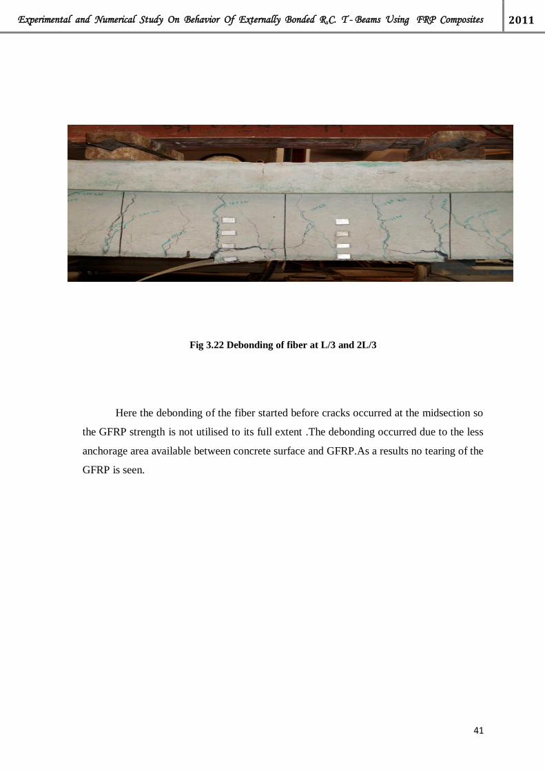
Experimental and Numerical Study On Behavior Of Externally Bonded R.C. T - Beams Using FRP Composites 2011
41
Fig 3.22 Debonding of fiber at L/3 and 2L/3
Here the debonding of the fiber started before cracks occurred at the midsection so
the GFRP strength is not utilised to its full extent .The debonding occurred due to the less
anchorage area available between concrete surface and GFRP.As a results no tearing of the
GFRP is seen.

Experimental and Numerical Study On Behavior Of Externally Bonded R.C. T - Beams Using FRP Composites 2011
42
Table 3.9 Deflection Values of Beam 3
LOAD
(in KN)
At Point L/3
(in mm)
At Point L/2
(in mm)
Remarks
0 0 0
20 .27 .29
30 .35 .38
40 .45 .50
50 .56 .61
60 .68 .74
70 .78 .85
80 .92 1.00
90 1.03 1.14
100 1.19 1.32
110 1.28 141
120 1.42 1.58
130 1.55 1.73 Hair line cracks appeared at
125
140 1.80 2.00
150 1.90 2.11
160 2.13 2.36
170 2.27 2.50
180 2.48 2.71
190 2.60 2.85
200 2.78 3.04
210 2.95 3.21
220 3.10 3.37
230 3.28 3.58
240 3.43 3.74
250 3.61 3.93
260 3.80 4.11
270 4.20 4.50 Debonding occured
290 Ultimate load Debonding but no tearing

Experimental and Numerical Study On Behavior Of Externally Bonded R.C. T - Beams Using FRP Composites 2011
43
3.5.1.4 BEAM-4
U- Jacketed Single Layered GFRP bonded from end to end
Fig 3.23 U-jacketed GFRP wrapped on the Beam 4
Fig 3.24 Beam 4 after testing

Experimental and Numerical Study On Behavior Of Externally Bonded R.C. T - Beams Using FRP Composites 2011
44
Fig 3.25 Tearing of GFRP in Beam 4 at 300 KN
Fig 3.26 Crack developed in Beam 4 under the GFRP
As the cracks developed under the GFRF are within 1000 mm at the mid section therefore
in Beam 5 U Jacketed wrapping is done only for that 1000 mm in the mid section.

Experimental and Numerical Study On Behavior Of Externally Bonded R.C. T - Beams Using FRP Composites 2011
45
Table 3.10 deflection values of beam 4
LOAD
(inKN)
At Point L/3
(in mm)
At Point L/2
(in mm)
Remarks
0 0 0
20 .28 .24
30 .38 .35
40 .49 .45
50 .59 .58
60 .69 .71
70 .84 .89
80 .95 1.03
90 1.10 1.20
100 1.25 1.37
110 1.38 1.53
120 1.56 1.71
130 1.72 1.88
140 1.84 2.04
150 1.98 2.18
160 2.13 2.35
170 2.28 2.51
180 2.48 2.75
190 2.63 2.92
200 2.79 3.10
210 2.95 3.26
220 3.08 3.43
230 3.26 3.63
240 3.41 3.78
250 3.55 3.96
260 3.73 4.15
270 4.65 5.40
280 6.95 7.60
290 Tearing started
318 Tearing and Debonding started simultaneously
330 Ultimate Load

Experimental and Numerical Study On Behavior Of Externally Bonded R.C. T - Beams Using FRP Composites 2011
46
3.5.1.4 BEAM-5
U- Jacketed Single Layered GFRP bonded only at the mid section
tearing
Fig. 3.27 Experimental Setup of the Beam 5

Experimental and Numerical Study On Behavior Of Externally Bonded R.C. T - Beams Using FRP Composites 2011
47
Fig. 3.28 Beam 5 after testing
Fig. 3.29 Tearing started at the mid section at 308 KN

Experimental and Numerical Study On Behavior Of Externally Bonded R.C. T - Beams Using FRP Composites 2011
48
Fig 3.30 After total tearing of the fiber at the midsection debonding started at the end of the
fiber. At the top the debonding occurred up to 2L/3.
Fig 3.31Crack developed under GFRP in BEAM 5

Experimental and Numerical Study On Behavior Of Externally Bonded R.C. T - Beams Using FRP Composites 2011
49
Table 3.11 Deflection values of Beam 5
LOAD
(in KN)
At Point L/3
(in mm)
At Point L/2
(in mm)
Remarks
0 0 0
20 .27 .27
30 .32 .32
40 .40 .41
50 .48 .51
60 .60 .64
70 .70 .77
80 .82 .92
90 .92 1.02
100 1.03 1.15
110 1.15 1.30
120 1.30 1.45
130 1.47 1.68
140 1.61 1.82
150 1.75 1.97
160 1.85 2.14
170 2.08 2.31
180 2.23 2.48
190 2.38 2.66
200 2.53 2.81
210 268 2.99
220 2.84 3.15
230 2.96 3.30
240 3.11 3.48
250 3.27 3.65
260 3.42 3.81
270 3.62 4.03
280 3.78 4.21
294 4.40 5.00 Tearing started
309 Tearing and debonding started
316 Ultimate Load

Experimental and Numerical Study On Behavior Of Externally Bonded R.C. T - Beams Using FRP Composites 2011
50
3.5.1.6 BEAM-6
U- Jacketed Single Layered GFRP retrofitted on cracked beam at the mid section.
Cracked Beam. Retrofitted beam
Fig 3.32 Crack formed after initial loading in Beam 6
Fig 3.33 Magnified picture of the hair line cracks formed during the initial loading in Beam 6

Experimental and Numerical Study On Behavior Of Externally Bonded R.C. T - Beams Using FRP Composites 2011
51
Fig 3.34 Retrofitted Beam 6
Fig 3.35 Debonding of the Retrofitted Beam 6
Fig 3.36 Crack pattern under the GFRP in Beam 6

Experimental and Numerical Study On Behavior Of Externally Bonded R.C. T - Beams Using FRP Composites 2011
52
Table 3.12 Deflection of BEAM 6 (before retrofitting)
LOAD
(in KN)
At Point L/3
(in mm)
At Point L/2
(in mm)
Remarks
0 0 0
20 .30 .36
30 .36 .44
40 .46 .56
50 .58 .68
60 .71 .82
70 .83 .94
80 .97 1.07
90 1.11 1.23
100 1.25 1.37
110 1.4 1.54
120 1.54 1.69
130 1.70 1.87
140 1.85 2.02
150 2.00 2.20

Experimental and Numerical Study On Behavior Of Externally Bonded R.C. T - Beams Using FRP Composites 2011
53
Table 3.13 Deflection of Beam 6 (after retrofitting)
LOAD
(in KN)
At Point L/3
(in mm)
At Point L/2
(in mm)
Remarks
0 0 0
30 .37 .42
40 .48 .54
50 .58 .64
60 .67 .74
70 .76 .85
80 .87 .98
90 .97 1.08
100 1.05 1.17
110 1.15 1.28
120 1.25 1.39
130 1.35 1.51
140 1.45 1.65
150 1.57 1.74
160 1.68 1.87
170 1.79 1.99
180 1.97 2.16
190 2.10 2.30
200 2.25 2.48
210 2.50 2.70
220 2.68 2.91
230 2.85 3.08
240 3.00 3.24
250 3.15 3.41
260 3.38 3.70
270 4.90 6.10

Experimental and Numerical Study On Behavior Of Externally Bonded R.C. T - Beams Using FRP Composites 2011
54
3.5.1.7 BEAM-7
U- Jacketed Single Layered GFRP retrofitted on cracked beam from end to end.
Cracked Beam. Retrofitted beam
Fig 3.37 Crack patterns after initial loading in Beam 7
Fig 3.38 Magnified picture of the crack patterns in Beam 7

Experimental and Numerical Study On Behavior Of Externally Bonded R.C. T - Beams Using FRP Composites 2011
55
Fig 3.39 Retrofitted Beam 7
Fig 3.40 Tearing of GFRP in Beam 7
Fig 3.41 Cracks under GFRP in Beam 7

Experimental and Numerical Study On Behavior Of Externally Bonded R.C. T - Beams Using FRP Composites 2011
56
Table 3.14 Deflection of Beam 7(before retrofitting)
LOAD
(in KN)
At Point L/3
(in mm)
At Point L/2
(in mm)
Remarks
0 0 0
.45 .52
40 .54 .63
50 .64 .75
60 .75 .86
70 .85 .98
80 .96 1.12
90 1.08 1.28
100 1.21 1.41
110 1.35 1.58
120 1.49 1.73
130 1.63 1.88
140 1.79 2.05
150 1.96 2.25

Experimental and Numerical Study On Behavior Of Externally Bonded R.C. T - Beams Using FRP Composites 2011
57
Table 3.15 Deflection of Beam-7(after retrofitting)
LOAD
(in KN)
At Point L/3
(in mm)
At Point L/2
(in mm)
Remarks
0 0 0
20 .44 .45
30 .53 .55
40 .65 .68
50 .79 .83
60 .90 .96
70 1.01 1.09
80 1.13 1.22
90 1.24 1.36
100 1.35 1.48
110 1.46 1.60
120 1.58 1.72
130 1.69 1.84
140 1.81 1.96
150 1.93 2.10
160 2.05 2.22
170 2.19 2.38
180 2.31 2.55
190 2.52 2.72
200 2.68 2.89
210 2.82 3.06
220 2.98 3.23
230 3.14 3.41
240 3.32 3.62
250 3.48 3.78
260 3.68 4.01
270 Debonding
306 Tearing
326 Ultimate

Experimental and Numerical Study On Behavior Of Externally Bonded R.C. T - Beams Using FRP Composites 2011
58
CHAPTER -4 RESULTS AND DISCUSSIONS
4.1 INTRODUCTION
In this chapter the experimental results of all the beams with different types of layering
of GFRP are interpreted. Their behavior throughout the test is described using recorded data
on deflection behavior and the ultimate load carrying capacity. The crack patterns and the
mode of failure of each beam are also described in this chapter. All the beams are tested for
their ultimate strengths.Beams-1 is taken as the control beam. It is observed that the control
beam had less load carrying capacity and high deflection values compared to that of the
externally strengthened beams using GFRP sheets.
All the beams except the control beam are strengthened with GFRP sheets in different
patterns.Beam-2 is strengthened only at the soffit from end to end. Beam-3 is also
strengthened only at the soffit but for the length L/3 to 2L/3. In Beam-4 the web part is
strengthened throughout its length with U-Jacketed single layered GFRP. Beam-5 is also
strengthened in the web but for 1 m length in the middle portion where most of the cracks are
occurring. Beam-6 is first loaded till hairline cracks are formed then it is retrofitted in similar
pattern as is done for Beam-5. Beam-7 is also loaded till hairline cracks are formed then it is
retrofitted in similar pattern as is done for Beam-4.Deflection behavior and the ultimate load
carrying capacity of the beams are noted. The ultimate load carrying capacity of all the beams
along with the nature of failure is given in Table 4.1.
4.2 FAILURE MODES
The following failure modes are be investigated for a GFRP strengthened section:
• Yielding of the steel in tension followed by rupture of the GFRP laminate;
• Yielding of the steel in tension followed by concrete crushing;
• Debonding of the FRP from the concrete substrate (FRP debonding).
A number of failure modes have been observed in the experiments of RC T- beams
strengthened in flexure and shear by GFRPs. These include flexure failure, flexural failure due
to GFRP rupture and crushing of concrete at the top. Rupture of the FRP laminate is assumed
to occur if the strain in the FRP reaches its design rupture strain before the concrete reaches its

Experimental and Numerical Study On Behavior Of Externally Bonded R.C. T - Beams Using FRP Composites 2011
59
maximum usable strain.GFRP debonding can occur if the force in the FRP cannot be sustained
by the substrate. In order to prevent debonding of the GFRP laminate, a limitation should be
placed on the strain level developed in the laminate.
The GFRP strengthened beam and the control beams are tested to find out their
ultimate load carrying capacity. It is found that all the failed in flexure. Beam-2 failed due to
fracture of GFRP sheet and then flexural failure of the beam took place. Beam-3 failed due to
debonding of the GFRP sheet and then flexural failure of the beam. Beam-4 failed due to
fracture of GFRP at the center followed by debonding and finally flexural failure of the
beam.Beam-5 failed in the manner as in Beam-4. Beam-6 failed due to debonding of GFRP
and then flexural failure of beam. In Beam-7 first fracture of GFRP took place at the center
followed by debonding of the top portion in the center.
4.3 LOAD DEFLECTION ANALYSIS
Here the deflection of each beam at different positions is analyzed. Mid-span
deflections of each beam are compared with the control beam. Also the load deflection
behavior is compared between different wrapping schemes having the same reinforcement. It
is noted that the behavior of the flexure deficient beams when bonded with GFRP sheets are
better than the control beams. The mid-span deflections are lower when bonded externally
with GFRP sheets. The use of GFRP sheet had effect in delaying the growth of crack
formation.
When all the wrapping schemes are considered it is found that the Beam-6 with GFRP
sheet in wrapped in the web for a length of 1m in the middle part had a better load deflection
behavior compared to the others strengthened beams with GFRP.

Experimental and Numerical Study On Behavior Of Externally Bonded R.C. T - Beams Using FRP Composites 2011
60
Fig. 4.1 Load vs. Deflection Curve for Control Beam 1
Beam 1 is taken as the control beam which is weak in flexure. In Beam1 no
strengthening is done. Two point static loading is applied on the beam and at the each
increment of the load, deflection at L/3, L/2 and 2L/3 are taken with the help of dial gauges.
Using this load and deflection data, load vs. deflection curve is plotted. At the load of 120 KN
initial hairline cracks appeared. Later with the increase in loading values the crack propagated
further. The Beam1 failed completely in flexure
0
50
100
150
200
250
300
0 0.5 1 1.5 2 2.5 3 3.5 4 4.5
Loa
d in
KN
Deflection in mm
Load vs Deflection Curve for Beam-1
At L/3
At L/2

Experimental and Numerical Study On Behavior Of Externally Bonded R.C. T - Beams Using FRP Composites 2011
61
Fig. 4.2 Load vs. Deflection Curve for Beam 2
Beam-2 is strengthened only at the soffit from end to end .Two point static loading is
applied on the beam and at the each increment of the load, deflection at L/3, L/2 and 2L/3 are
taken with the help of dial gauges. Using this load and deflection data, load vs. deflection
curve is plotted. At the load of 130 KN initial hairline cracks appeared. Later with the increase
in loading values the crack propagated further. Beam-2 failed due to fracture of GFRP sheet
and then flexural failure of the beam took place.
0
50
100
150
200
250
300
350
0 1 2 3 4 5 6
Loa
d in
KN
Deflection in mm
Load vs Deflection Curve for Beam-2
At L/3
At L/2

Experimental and Numerical Study On Behavior Of Externally Bonded R.C. T - Beams Using FRP Composites 2011
62
Fig. 4.3 Load vs. Deflection Curve for Beam 3
Beam-3 is also strengthened only at the soffit but for the length L/3 to 2L/3. Two point
static loading is applied on the beam and at the each increment of the load, deflection at L/3,
L/2 and 2L/3 are taken with the help of dial gauges. Using this load and deflection data, load
vs. deflection curve is plotted. At the load of 125 KN initial hairline cracks appeared. Later
with the increase in loading values the crack propagated further. Beam-3 failed due to
debonding of the GFRP sheet and then flexural failure of the beam.
0
50
100
150
200
250
300
0 1 2 3 4 5
Load
in K
N
Deflection in mm
Load vs Deflection Curve for Beam-3
At Point L/3
At Point L/2

Experimental and Numerical Study On Behavior Of Externally Bonded R.C. T - Beams Using FRP Composites 2011
63
Fig. 4.4 Load vs. Deflection Curve for Beam 4
In Beam-4 the web part is strengthened throughout its length with U-Jacketed single
layered GFRP. Two point static loading is applied on the beam and at the each increment of
the load, deflection at L/3, L/2 and 2L/3 are taken with the help of dial gauges. Using this load
and deflection data, load vs. deflection curve is plotted. No initial hairline cracks are visible
due to the covering of GFRP.Later with the increase in loading values the crack propagated
further under the GFRP. Beam-4 failed due to fracture of GFRP at the center followed by
debonding and finally flexural failure of the beam.
0
50
100
150
200
250
300
0 1 2 3 4 5 6 7 8
Loa
d in
KN
Deflection in mm
Load vs Deflection Curve for Beam-4
At Point L/3
At Point L/2

Experimental and Numerical Study On Behavior Of Externally Bonded R.C. T - Beams Using FRP Composites 2011
64
Fig 4.5 Load vs. Deflection Curve for Beam 5
Beam-5 is also strengthened in the web but for 1 m length in the middle portion where
most of the cracks are occurring. Two point static loading is applied on the beam and at the
each increment of the load, deflection at L/3, L/2 and 2L/3 are taken with the help of dial
gauges. Using this load and deflection data, load vs. deflection curve is plotted. No initial
hairline cracks are visible due to the covering of GFRP.
Later with the increase in loading values the crack propagated further under the GFRP.
Beam-5 failed in the manner as in Beam-4
0
50
100
150
200
250
300
350
0 1 2 3 4 5 6
Load
in K
N
Deflection in mm
Load vs Deflection Curve for Beam-5
At Point L/3
At Point L/2

Experimental and Numerical Study On Behavior Of Externally Bonded R.C. T - Beams Using FRP Composites 2011
65
Fig. 4.6 Load vs. Deflection Curve for Beam 4 before retrofitting
Beam-6 is first loaded till hairline cracks are formed then it is retrofitted with U-
Jacketed single layered GFRP for 1 m length in the middle portion. Two point static loading is
applied on the beam and at the each increment of the load, deflection at L/3, L/2 and 2L/3 are
taken with the help of dial gauges. Using this load and deflection data, load vs. deflection
curve is plotted. No initial hairline cracks are visible due to the covering of GFRP. Later with
the increase in loading values the crack propagated further under the GFRP. Beam-6 failed
due to debonding of GFRP and then flexural failure of beam.
0
20
40
60
80
100
120
140
160
0 0.5 1 1.5 2 2.5
Load
in K
N
Deflection in mm
Load vs Deflection Curve for Beam-6 before retrofitting
At Point L/3
At Point L/2

Experimental and Numerical Study On Behavior Of Externally Bonded R.C. T - Beams Using FRP Composites 2011
66
Fig. 4.7 Load vs. Deflection Curve for Beam 6 after retrofitting
0
50
100
150
200
250
300
0 1 2 3 4 5 6 7
Load
in K
N
Deflection in mm
Load vs Deflection Curve for Beam-6 after retroffiting
At Point L/3
At Point L/2

Experimental and Numerical Study On Behavior Of Externally Bonded R.C. T - Beams Using FRP Composites 2011
67
Fig. 4.8 Load vs. Deflection Curve for Beam 6 before and after retrofitting
Here it is studied that the deflection of the Beam 6 taken at the centre is controlled in the
case of retrofitting.
0
20
40
60
80
100
120
140
160
0 0.5 1 1.5 2 2.5
Load
in K
N
Deflection in mm
Load vs Deflection Curve for Beam-6 at L/2
at l/2 Before Retrofitting
at l/2 After Retrofitting

Experimental and Numerical Study On Behavior Of Externally Bonded R.C. T - Beams Using FRP Composites 2011
68
Fig.4.9 Load vs. Deflection Curve for Beam 7 before retrofitting
Beam-7 is first loaded till hairline cracks are formed then it is retrofitted with U-
Jacketed single layered GFRP from end to end. Two point static loading is applied on the
beam and at the each increment of the load, deflection at L/3, L/2 and 2L/3 are taken with the
help of dial gauges. Using this load and deflection data, load vs. deflection curve is plotted.
No initial hairline cracks are visible due to the covering of GFRP. Later with the increase in
loading values the crack propagated further under the GFRP. In Beam-7 first fracture of GFRP
took place at the center followed by debonding of the top portion in the center.
0
20
40
60
80
100
120
140
160
0 0.5 1 1.5 2 2.5
Load
in K
N
Deflection in mm
Load vs Deflection Curve for Beam-7 Before Retrofitting
At Point L/3
At Point L/2
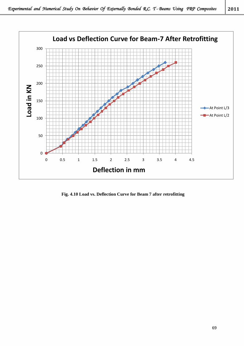
Experimental and Numerical Study On Behavior Of Externally Bonded R.C. T - Beams Using FRP Composites 2011
69
Fig. 4.10 Load vs. Deflection Curve for Beam 7 after retrofitting
0
50
100
150
200
250
300
0 0.5 1 1.5 2 2.5 3 3.5 4 4.5
Load
in K
N
Deflection in mm
Load vs Deflection Curve for Beam-7 After Retrofitting
At Point L/3
At Point L/2

Experimental and Numerical Study On Behavior Of Externally Bonded R.C. T - Beams Using FRP Composites 2011
70
Fig. 4.11 Load vs. Deflection Curve for Beam 6 before and after retrofitting
Here it is observed that how the deflection of the Beam 7 taken at the centre is controlled
after retrofitting.
0
20
40
60
80
100
120
140
160
0 0.5 1 1.5 2 2.5
Load
in K
N
Deflection in mm
Load vs Deflection Curve for Beam-7 at L/2
Before Retrofitting
After Retrofitting

Experimental and Numerical Study On Behavior Of Externally Bonded R.C. T - Beams Using FRP Composites 2011
71
Fig.4.12 Load vs. Deflection Curve for Beam 1 and 2
From this figure it is observed that deflection in case of Beam-2 which has been
strengthened with GFRP at the soffit is controlled to a certain extent with respect to the
control Beam 1.And the ultimate load has also increased to a certain percentage which has
been illustrated in the figure 4.28
0
50
100
150
200
250
300
0 0.5 1 1.5 2 2.5 3 3.5 4 4.5
Load
in K
N
Deflection in mm
Load vs Deflection Curve for Beam 1 and Beam 2
Beam 1
Beam 2

Experimental and Numerical Study On Behavior Of Externally Bonded R.C. T - Beams Using FRP Composites 2011
72
Fig. 4.13 Load vs. Deflection Curve for Beam 1 and Beam 3
From this figure 4.12 it is interpreted that deflection in case of Beam-3 which has been
strengthened with GFRP only at the soffit but for the length L/3 to 2L/3 is controlled to a
certain extent with respect to the Control Beam 1.And the ultimate load has also increased to a
certain percentage which has been illustrated in the figure 4.28.
0
50
100
150
200
250
300
0 0.5 1 1.5 2 2.5 3 3.5 4 4.5
Load
in K
N
Deflection in mm
Load vs Deflection Curve for Beam 1 and Beam 3
Beam 1
Beam 3

Experimental and Numerical Study On Behavior Of Externally Bonded R.C. T - Beams Using FRP Composites 2011
73
Fig. 4.14 Load vs. Deflection Curve for Beam 1 and Beam 4
It is observed from the fig 4.13 that deflection in case of Beam-4 which has been
strengthened in the web part throughout its length with U-Jacketed single layered GFRP is
controlled to a certain extent with respect to the Control Beam 1.And the ultimate load has
also increased to a certain percentage which has been illustrated in the fig 4.28.
0
50
100
150
200
250
300
0 0.5 1 1.5 2 2.5 3 3.5 4 4.5
Load
in K
N
Deflection in mm
Load vs Deflection Curve for Beam 1 and Beam 4
Beam 1
Beam 4

Experimental and Numerical Study On Behavior Of Externally Bonded R.C. T - Beams Using FRP Composites 2011
74
Fig. 4.15 Load vs. Deflection Curve for Beam 1 and Beam 5
From this figure it is studied that deflection in case of Beam-5 which has been
strengthened in the web part for a length of 1 m length with U-Jacketed single layered GFRP
is controlled to a much greater extent with respect to the Control Beam 1.And the ultimate
load has also increased to a certain percentage which has been illustrated in the fig 4.28
0
50
100
150
200
250
300
0 0.5 1 1.5 2 2.5 3 3.5 4 4.5
Load
in K
N
Deflection in mm
Load vs Deflection Curve for Beam 1 and Beam 5
Beam 1
Beam 5

Experimental and Numerical Study On Behavior Of Externally Bonded R.C. T - Beams Using FRP Composites 2011
75
Fig. 4.16 Load vs. Deflection Curve for Beam 1 and Beam 6
From this figure 4.16 it is observed that deflection in case of Beam-6 which has been
first cracked till initial hairline cracks appeared and then strengthened in its the web part for a
length of 1 m length with U-Jacketed single layered GFRP is controlled to the maximum
extent with respect to the Control Beam 1 and other strengthened beams .And the ultimate
load has also increased to a certain percentage which has been illustrated in the fig 4.28.
0
50
100
150
200
250
300
0 0.5 1 1.5 2 2.5 3 3.5 4 4.5
Load
in K
N
Deflection in mm
Load vs Deflection Curve for Beam 1 and Beam 6
Beam 1
Beam 6

Experimental and Numerical Study On Behavior Of Externally Bonded R.C. T - Beams Using FRP Composites 2011
76
Fig. 4.17 Load vs. Deflection Curve for Beam 1 and Beam 7
From this figure 4.17 it can be interpreted that deflection in case of Beam-7 which has
been first cracked till initial hairline cracks appeared and then strengthened in its the web part
throughout its length with U-Jacketed single layered GFRP is controlled to the good extent
with respect to the Control Beam 1 and but less than Beam-6 .And the ultimate load has also
increased to a certain percentage which has been illustrated in the fig 4.28.
0
50
100
150
200
250
300
0 0.5 1 1.5 2 2.5 3 3.5 4 4.5
Load
in K
N
Deflection in mm
Load vs Deflection Curve for Beam 1 and Beam 7
Beam 1
Beam 7

Experimental and Numerical Study On Behavior Of Externally Bonded R.C. T - Beams Using FRP Composites 2011
77
Fig. 4.18 Load vs. Deflection Curve for Beam 2 and Beam 3
Here in the figure 4.18 deflection of the beam 2 and beam 3 has been compared which
shows that beam 3 which is strengthened with GFRP only at soffit for a length from L/3 to
2L/3 has less deflection as compared to beam 2 which is strengthened at soffit throughout its
length.
0
50
100
150
200
250
300
0 1 2 3 4 5
Load
in K
N
Deflection in mm
Load vs Deflection Curve for Beam 2 and Beam 3
Beam 2
Beam 3

Experimental and Numerical Study On Behavior Of Externally Bonded R.C. T - Beams Using FRP Composites 2011
78
Fig. 4.19 Load vs. Deflection Curve for Beam 4 and Beam 5
Here in the figure 4.19 deflection of the beam 4 and beam 5 has been compared which
shows that beam 5 which is strengthened with U-Jacketed single layered GFRP in the web part
for a length of 1 m has less deflection as compared to beam 4 which is strengthened with U-
Jacketed single layered GFRP in the web part throughout its length
0
50
100
150
200
250
300
0 1 2 3 4 5 6
Load
in K
N
Deflection in mm
Load vs Deflection Curve for Beam 4 and Beam 5
Beam 4
Beam 5

Experimental and Numerical Study On Behavior Of Externally Bonded R.C. T - Beams Using FRP Composites 2011
79
Fig. 4.20 Load vs. Deflection Curve for Beam 1, 2, 3, 4 and Beam 5
Here the all strengthened beam are compared with each other and also with
the control Beam 1. And from the figure 4.20 it can be interpreted that beam 5 which is
strengthened with U-Jacketed single layered GFRP in the web part for a length of 1 m has
minimum deflection as compared to others.
0
50
100
150
200
250
300
0 0.5 1 1.5 2 2.5 3 3.5 4 4.5
Load
in K
N
Deflection in mm
Load vs Deflection Curve for Beams 1,2,3, 4 and 5
Beam 1
Beam 2
Beam 3
Beam 4
Beam 5

Experimental and Numerical Study On Behavior Of Externally Bonded R.C. T - Beams Using FRP Composites 2011
80
Fig. 4.21 Load vs. Deflection Curve for Beam 6 and Beam 7
Here the beam 6 and beam 7 are compared which are retrofitted after initial
hairline cracks are observed. And from the graph we can interpret that deflection in the case of
beam 6 is less than that of beam 7.
0
50
100
150
200
250
300
0 0.5 1 1.5 2 2.5 3 3.5 4 4.5
Load
in K
N
Deflection in mm
Load vs Deflection Curve for Beam 6 and Beam 7
Beam 6
Beam 7

Experimental and Numerical Study On Behavior Of Externally Bonded R.C. T - Beams Using FRP Composites 2011
81
Fig. 4.22 Load vs. Deflection Curve for all the Beams
Here all the beams are compared with respect to their deflection and load data. And
it can be interpreted that beam 6 which is retrofitted with U-Jacketed single layered GFRP
sheet for a length of 1 m in the middle section of the beam where most of the cracks are
occurring has minimum deflection value as compared to others.
0
50
100
150
200
250
300
0 0.5 1 1.5 2 2.5 3 3.5 4 4.5
Load
in K
N
Deflection in mm
Load vs Deflection Curve for All the Beams
Beam 1
Beam 2
Beam 3
Beam 4
Beam 5
Beam 6
Beam 7

Experimental and Numerical Study On Behavior Of Externally Bonded R.C. T - Beams Using FRP Composites 2011
82
Fig. 4.23 Load vs. Deflection Curve for Beam 5 and Beam 6
Here beam 5 and beam 6 are compared. Both the beams are having same wrapping
pattern but beam 5 is strengthened from the starting where as beam 6 is retrofitted with U-
Jacketed single layered GFRP sheet for a length of 1 m in the middle section after initial
hairline cracks are formed. And from the figure 4.23 it can be interpreted that in the initial
stages of loading the retrofitted beam i.e. beam no 6 is showing more deflection but as the
load value is increased the retrofitted beam is showing less deflection.
0
50
100
150
200
250
300
0 0.5 1 1.5 2 2.5 3 3.5 4 4.5
Load
in K
N
Deflection in mm
Load vs Deflection Curve for Beam 5 and Beam 6
Beam 5
Beam 6

Experimental and Numerical Study On Behavior Of Externally Bonded R.C. T - Beams Using FRP Composites 2011
83
Fig. 4.24 Load vs. Deflection Curve for Beam 4 and Beam 7
Here beam 4 and beam 7 are having same wrapping pattern but beam 4 is
strengthened from the starting where as beam 6 is retrofitted with U-Jacketed single
layered GFRP sheet throughout its length after initial hairline cracks are formed. And from
the figure 4.24 it can be interpreted that in the initial stages of loading the retrofitted beam
i.e. beam no 7 is showing more deflection but as the load value is increased the retrofitted
beam is showing less deflection.
0
50
100
150
200
250
300
0 0.5 1 1.5 2 2.5 3 3.5 4 4.5
Load
in K
N
Deflection in mm
Load vs Deflection Curve for Beam 4 and Beam 7
Beam 4
Beam 7

Experimental and Numerical Study On Behavior Of Externally Bonded R.C. T - Beams Using FRP Composites 2011
84
Following are the values of deflection Control Beam 1 obtained from finite element
modelling and IS code method using Matlab program and it is compared with
experimental values in the graphs.
Table 4.1 Deflection of Control Beam 1 from different methods
LOAD
(in KN)
FEM
(in mm)
IS CODE
(in mm)
EXPERIMENTAL
(in mm)
20 0.294 0.156 0.440
30 0.427 0.338 0.630
40 0.560 0.52 0.760
50 0.693 0.701 0.890
60 0.826 0.882 1.020
70 0.958 1.063 1.200
80 1.091 1.244 1.330
90 1.224 1.425 1.540
100 1.357 1.606 1.740
110 1.490 1.787 1.880
120 1.622 1.968 2.100
130 1.755 2.149 2.230
140 1.888 2.329 2.400
150 2.021 2.510 2.520
160 2.154 2.691 2.730
170 2.2867 2.872 2.950
180 2.419 3.053 3.160
190 2.552 3.234 3.320
200 2.685 3.415 3.480
210 2.818 3.595 3.630
220 2.950 3.776 3.840
230 3.083 3.957 3.970
240 3.216 4.138 4.170

Experimental and Numerical Study On Behavior Of Externally Bonded R.C. T - Beams Using FRP Composites 2011
85
Fig. 4.25Load vs. Deflection Curve for Control Beam 1 using different methods
From the figure 4.25 it is observed that the central deflection of the T-beam obtained
from experiment compare well with the results using IS Code method. It is also observed from
the figure that at lower loads the values of Finite element model is closer to the experimental
values but at higher loads it is varying because here linear finite element modeling have been
used to find the deflections.
0
50
100
150
200
250
300
0 0.5 1 1.5 2 2.5 3 3.5 4 4.5
Load
in K
N
Deflection in mm
BEAM 1
FEM
IS CODE
EXPERIMENTAL

Experimental and Numerical Study On Behavior Of Externally Bonded R.C. T - Beams Using FRP Composites 2011
86
Following are the values of deflection for Beam 2 obtained from finite element
modelling and IS code method using Matlab program and it is compared with experimental
values in the graphs
Table 4.2 Deflection of Beam 2 from different methods
LOAD
(in KN)
FEM
(in mm)
IS code
(in mm)
EXPERIMENTAL
(in mm)
20 0.289 0.154 .310
30 0.420 0.334 .440
40 0.551 0.513 .550
50 0.682 0.691 .670
60 0.812 0.869 .870
70 0.943 1.047 .990
80 1.074 1.226 1.170
90 1.205 1.404 1.330
100 1.335 1.582 1.510
110 1.466 1.760 1.650
120 1.597 1.938 1.850
130 1.728 2.116 1.990
140 1.858 2.294 2.150
150 1.989 2.472 2.320
160 2.120 2.650 2.490
170 2.251 2.828 2.660
180 2.381 3.006 2.810
190 2.512 3.184 2.980
200 2.643 3.363 3.100
210 2.774 3.541 3.230
220 2.904 3.719 3.390
230 3.035 3.897 3.540
240 3.166 4.075 3.680

Experimental and Numerical Study On Behavior Of Externally Bonded R.C. T - Beams Using FRP Composites 2011
87
Fig. 4.26 Load vs. Deflection Curve for Beam 2 using different methods
It can be studied from the figure 4.26 that the values of deflection obtained from finite
element modeling at lower loads are agreeing with experimental values. But at higher load it is
varying as linear finite element modeling is used. Further it can be observed that the
experimental values of deflection are agreeing with value of deflection found by IS code
method. Here the values of deflection in case of FEM are lower than IS code because in case
of FEM total gross section is considered where as in IS code method crack section is
considered.
0
50
100
150
200
250
300
0 0.5 1 1.5 2 2.5 3 3.5 4 4.5
Load
in K
N
Deflection in mm
BEAM 2
FEM
IS CODE
EXPERIMENTAL

Experimental and Numerical Study On Behavior Of Externally Bonded R.C. T - Beams Using FRP Composites 2011
88
4.4 ULTIMATE LOAD CARRING CAPACITY
The load carrying capacity of the control beams and the strengthen beam are plotted below. It
is observed that beam 4 is having the max load carrying capacity.
Fig. 4.27 Ultimate Load carrying capacity
Beam 1 Beam 2 Beam 3 Beam 4 Beam 5 Beam 6 Beam 7
LOAD 240 310 290 330 316 312 326
0
50
100
150
200
250
300
350
Axi
s Ti
tle
LOAD

Experimental and Numerical Study On Behavior Of Externally Bonded R.C. T - Beams Using FRP Composites 2011
89
Fig. 4.28 Percentage increase in the Ultimate Carrying capacity w.r.t Control Beam 1
From the above figure we can observe the amount of increase in the flexural
strength for each strengthened beam with respect to the Control Beam 1
Beam 2 Beam 3 Beam 4 Beam 5 Beam 6 Beam 7
PERCENTAGE 29.2 20.8 37.6 31.6 30 35.8
0
5
10
15
20
25
30
35
40
PER
CEN
TAG
EINCREASE IN LOAD CARRYING CAPACITY

Experimental and Numerical Study On Behavior Of Externally Bonded R.C. T - Beams Using FRP Composites 2011
90
CHAPTER 5
CONCLUSIONS
5.1 CONCLUSIONS
The present experimental study is done on the flexural behavior of reinforced concrete
T-beams strengthened by GFRP sheets. Seven reinforced concrete (RC) T-beams weak in
flexure having same reinforcement detailing are casted and tested. From the test results and
calculated strength values, the following conclusions are drawn:
1. The ultimate load carrying capacity of all the strengthen beams were enhanced as
compared to the Control Beam1.
2. Initial flexural cracks appear for higher loads in case of strengthened beams.
3. The load carrying capacity of the strengthened Beam 4 was found to be maximum of
all the beams. It increased up to 37.5 % more than the control beam 1, 6.5% more than
strengthened beam 2 and 4.4 % more than the strengthened beam 5.
4. Beam 6 which was retrofitted in the web part only for 1 m length in the center showed
minimum deflection values on same loads as compared to other strengthened beams
and the control beam.
5. Beam 4 and Beam 7 were giving the best results in terms of load carrying capacity and
deflection respectively. And both are having same wrapping pattern of GFRP which is
bonded in the web part throughout its length.
6. Flexural strengthening in the web part throughout the length of the beam increases the
ultimate load carrying capacity, but it is comparatively close to ultimate load carrying
capacity of the beam strengthen at the soffit only so it is economically effective to use
strengthen only at the soffit of the beam and the cracks developed were not visible in
the former because of the side wrapping so it gives less warning compared to the
beams strengthen only at the soffit of the beam

Experimental and Numerical Study On Behavior Of Externally Bonded R.C. T - Beams Using FRP Composites 2011
91
5.2 SCOPE OF THE FUTURE WORK
It promises a great scope for future studies. Following areas are considered for future research:
Strengthening of beam weak in shear.
Effect on torsional strength due to retrofitting
Developing a non linear finite element model for the analysis of the strengthened RC
T-Beams using various configuration of FRP strengthening.
Variation of beam dimension.
Strengthening of T- Beam with different type of FRP (like Carbon fiber reinforced
polymer),.

Experimental and Numerical Study On Behavior Of Externally Bonded R.C. T - Beams Using FRP Composites 2011
92
CHAPTER 6
REFERENCES
1. ACI Committee 440 (1996) State Of Art Report On Fiber Reinforced Plastic
Reinforcement For Concrete Structure ,ACI 440R-96, American Concrete Institute ,
Farmington Hills, Michigan
2. Aidoo, J. Harries, K. A., and Petrou, M. F. (2004), “ Fatigue behaviour of CFRP
strengthened reinforced concrete bridge girders”, ASCE Journal of Composites for
Construction, Vol. 7, No. 6, pp. 501-518.
3. Aiello, M. A., and Ombres, L. (2004), “Cracking and deformability analysis of reinforced
concrete beams strengthened with externally bonded carbon fiber reinforced polymer
sheet”, ASCE Journal of Materials in Civil Engineering, Vol.16, No. 5, pp.292-399.
4. Alagusuundaramoorthy, P., Harik, I. E., and Choo, C. C. (2003), “Flexural behaviour of
RC beams strengthened with carbon fibre reinforced polymer sheets or fabric”’ ASCE
journal of Composites for Construction, Vol. 7, No.4, pp.292-301.
5. Arduini, M., and Nanni, A. (1997), “Behaviour of pre-cracked R. C. beams strengthened
with carbon FRP sheets”, ASCE Journal of Composites for Construction, Vol. 1, No. 2, pp.
63-70.
6. Arduni, M., Di-Tommaso, A., and Nani, A. (1997), “A brittle failure in FRP plate and
sheet bonded beams”, ACI Structural Journal, Vol. 94, No. 4, pp. 363-370.
7. Barnes, A. R., and Mays, C.G. 1999), Fatigue performance of concrete beams
strengthened with CFRP plates”, ASCE Journal of Composites for Construction. Vol. 3,
No. 2, pp. 63-72.
8. Benacardino, F., Spadea, G., and Swamy, R. N. (2002), “Strength and ductility of
reinforced concrete beams externally reinforced with carbon fibre fabric”, ACI Structural
Journal, Vol. 99, No. 2, pp. 163-171.
9. Bencardino, F., Colotti, V., Spadea, G., and Swamy, R. N. (2005), “Shear behaviour of
reinforced concrete beams strengthened in flexure with bonded carbon fibre reinforced
polymer laminates”, Canadian Journal of Civil Engineering, Vol. 32, No. 5, pp. 812-824.
Experimental and Numerical Study On Behavior Of Externally Bonded R.C. T - Beams Using FRP Composites 2011
93
10. Chaallal, O., and Shahawy, M. (2000). "Performance of Fiber-Reinforced Polymer-
Wrapped Reinforced Concrete Column under Combined Axial-Flexural Loading," ACI
Structural Journal Vol. 97, No. 4, pp 659-668.
11. Chajes, M. J., Thomson, T., Finch, W. W., and Januszka, T. (1994), “Flexural
strengthening of concrete beams using externally bonded composite materials”,
Construction and Building Materials, Vol.8, No. 3, pp.191-201.
12. Chajes, M. J., Thomson, T., Finch, W. W., and Januszka, T. F., and Thomson, T. A.
(1996), “Bond and force transfer of composite material plate bonded to concrete”, ACI
Structural Journal, Vol. 93, No. 2, pp. 208-217.
13. FIB Bulletin 14 Technical Report: 2001, “Externally Bonded FRP Reinforcement for RC
Structures”, International Federation of Structural Concrete, Laussanne.
14. Gao, B., Leung, C. K. Y., and Kim, J. K. (2007), “Failure diagrams of FRP strengthened
RC beams”, Composite Structures, Vol. 77, No. 4, pp. 493-508.
15. Garden, H. N., Quantrill, R. J., Hollaway, L. C., Throne, A. M., and Parke, G. A. R.
(1998), “An experimental study of the anchorage length of carbon fibre composite plates”,
Construction and Building Materials, Vol. 12, No.1, pp. 203-219.
16. Grace, N. F. (2001), “Strengthening of negative moment region of reinforced concrete
beams using carbon fiber- reinforced polymer strips”. ACI Structural Journal, Vol. 98, No.
3, pp. 347-358.
17. Grace, N. F., Abdel-Sayed, G., Soliman, A. K., , and Saleh, K. R. (1999), Strengthening of
reinforced concrete beams using fibre reinforced polymer (FRP) laminates”, ACI
Structural Journal, Vol. 96, No. 5, pp. 865-874.
18. Grace, N. F., Soliman, A. K., Abdel-Sayed, G., and Saleh, K. R. (1999), “Strengthening of
continuous beams using fibre reinforced polymer laminates”, Proceedings of 4th
International Symposium on Fibre Reinforced Polymer Reinforcements for Reinforced
Concrete Structures, SP-188, American Concrete Institute, Farmington Hills, Michigan,
USA, pp.647-657.
19. Hoy, D. E., Warren, G. E., and Davis, D. A. (1996), “Environmentally acceptable piling
for use in Navy Pier Fender Systems”, Proceeding of 4th
ASCE Materials Conference on
Materials for the new Millennium, November 1996, Washington, DC.

Experimental and Numerical Study On Behavior Of Externally Bonded R.C. T - Beams Using FRP Composites 2011
94
20. ISIS Canada:2001, “Design Manuals Parts 1-4, Intelligent Sensing of Innovative
Structures, University of Manitoba, Winnipeg.
21. JBDPA (Japan Building Disaster Prevention Association):1999, “Seismic Retrofitting
Design and Construction Guidelines for Existing Reinforced Concrete (RC) Buildings with
FRP Materials”, In Japanese.
22. Kachlakev, D. and MerCurry, D. D. (2000), “ Behaviour of full-scale reinforced concrete
beams retrofitted for shear and flexure with FRP laminates”, Composites Part B:
Engineering, Vol.31, pp.445-452.
23. Kim, D., and Sebastian, W. M. (2002), “Parametric study of bond failure in concrete
beams with externally strengthened with fibre reinforced polymer plates”, Magazine of
Concrete Research, Vol. 54, No. 1, pp. 47-59.
24. Li, L. J., Guo, Y. C., Liu, F., and Bungey, J. H. (2006), “An experimental and numerical
study of the effects of thickness and length of CFRP on performance of repaired reinforced
concrete beams, Construction and Building Materials, Vol. 20, No.10, pp. 901-909.
25. Malek, A. M., Saadatmanesh, H., and Ehsani, M. R. (1998), “Prediction of failure load of
R/C strengthened with FRP plate due to stress concentration at the plate end”, ACI
Structural Journal, Vol. 95, No. 1, pp. 142-152.
26. Martinez X, Sergio Oller, Fernando Rastellini, Alex H. Barbat (2008) “A numerical
procedure simulating RC structures reinforced with FRP using serial/ parallel mixing
theory” Computers And Structures.
27. Masoud, S., Soudki, K., and Topper, T. (2001), “CFRP-strengthened and corroded
RCbeams under monotonic and fatigue loads”, ASCE Journal of Composites for
Construction, Vol. 5, No. 4, pp. 228-236.
28. Meier, U., Deuring, M., Meier, H., and Schwegler, G. (1992), “Strengthening of structures
with CFRP strips: Research and Applications in Switzerland”, Advanced Composite
Materials in Bridges and Structures, K. W. Neale and P. Labossiere, eds., Canadian
Society for Civil Engineers, Montreal, Quebec, Canada, pp.243-251.
29. Meier,U (1987) “Bridge Repair with high performance composite materials ,” Material
and technique , vol . 4 pp. 125-128 (in German)
30. Meier,U And Kaiser.H.P (1991) “Strenghtening Of Structures With Cfrp Laminates
,”Proceedings Of Advanced Composite Materials In Civil Engineering Stucture .
American Society Of Civil Engineers Specialty Conference

Experimental and Numerical Study On Behavior Of Externally Bonded R.C. T - Beams Using FRP Composites 2011
95
31. Nanni, A and Arduini, M (1997), “Behaviour of pre-cracked R. C. beams strengthened
with carbon FRP sheets”, ASCE Journal of Composites for Construction, Vol. 1, No. 2, pp.
63-70.
32. Nanni, A , Khalifa A (2000) “Improving shear capacity of existing RC T-section beams
using CFRP composites” Cement & Concrete Composites 22 (2000) 165-174
33. Nanni, A. (1995), “Concrete repair with externally bonded FRP reinforcement”, Concrete
International, Vol. 17, No. 6, pp. 22-26.
34. Nanni, A., and Norris, M. S. (1995), “FRP Jacketed Concrete under flexure and combined
flexural-compression”, Construction and Building Materials, Vol. 9, No. 5, pp. 273-281.
35. Norris, T., Saadatmanesh, H., and Ehsani, M. (1997), “Shear and flexural strengthening of
R/C beams with carbon fiber sheets”, ASCE Journal of Structural Engineering, Vol. 123,
No. 7, pp. 903-911.
36. Obaidat Yasmeen Taleb , Susanne Heyden , Ola Dahlblom , Ghazi Abu-Farsakh Yahia
Abdel-Jawad (2010) “Retrofitting of reinforced concrete beams using composite
laminates” Construction and Building Materials.
37. Odello, R. J. (2001), “Polymer composite retrofits strengthen concrete structures”, The
AMPTIAC Quarterly, Vol. 6, No. 4, pp. 25-29.
38. Papakonstantinou, C. G., Petrou, M. F., andHarries, K. A. (2001), “Fatigue of reinforced
concrete beams strengthened with GFRP sheets”, ASCE Journal of Composites for
Construction, Vol. 5, No. 4, pp. 246-253.
39. Pham, H., and Al-Mahaidi, R. (2004), “Experimental investigation into flexural retrofitting
of reinforced concrete bridge beam using FRP composites”, Composite Structures, Vol.
66, No. 4, pp. 617-625.
40. Quattlebaum, J., Harries, K. A., and Petrou, M. F. (2005), “Comparison of three CFRP
flexural retrofit systems under monotonic and fatigue loads”, ASCE Journal of Bridge
Engineering, Vol. No. pp. ASCE Journal of Composites for Construction, Vol. 7, No. 6,
pp.
41. Rajamohan S and Sundarraja C M (2008) “Strengthening of RC beams in shear using
GFRP inclined strips – An experimental study” Construction and Building Materials 23
(2009) 856–864

Experimental and Numerical Study On Behavior Of Externally Bonded R.C. T - Beams Using FRP Composites 2011
96
42. Richard, A. B., and Geoffrey, C. M. (1999), “Fatigue performance of concrete beams
strengthened with CFRP plates”, Journal of Composites for Construction, May
1999, pp. 63-72.
43. Ross, C. A., Jerome, D. M., Tedesco, J. W., and Hughes, M. L. (1999), “Strengthening of
reinforced concrete beams with externally bonded composite laminates”, ACI Structural
Journal, Vol. 96. No. 2, pp. 65-71..
44. Rubinsky, I. A., and Rubinsky, A. (1954), “An investigation into the use of fibre-glass for
prestressed concrete”, Magazine of Concrete Research, Vol.6.
45. Saadatmanesh, H., and Ehsani, M. R. (1991), “R. C. beams strengthened with FRP plates
I: Experimental study”, ASCE Journal of Structural Engineering, Vol. 117, No. 11, pp.
3417-3433.
46. Saadatmanesh, H., and Ehsani, M. R. (1990), “Fibre composite plates can strengthen
beams”, Concrete International, Vol. 12, No. 3, pp. 65-71.
47. Saadatmanesh, H., Ehsani, M. R., Li, M. W. (1994), “Strength and ductility of concrete
columns externally reinforced with fibre composite straps”, ACI Structural Journal,
Vol. 91, No. 4, pp. 434-447.
48. Sebastian, W. M. (2001), “Significance of mid-span de-bonding failure in FRP-plated
concrete beams”, ASCE Journal of Structural Engineering, Vol. 127, No. 7, pp.792-798.
49. Shahawy. M., Mirmiran .A., and Beitelman. T. (2000),” Tests and modelling of carbon
wrapped concrete columns”, Composites Part B: Engineering, Vol. 31, pp. 471-480.
50. Shahawy, M., and Beitelman, E. T. (1999), “Static and fatigue performance of R. C. beams
strengthened with CFRP laminates”, ASCE Journal of Structural Engineering, Vol. 125,
No. 6, pp. 613-621.
51. Sharif, A., Al-Sulaimani, G. J., Basunbul, I. A., Baluch, M. H., and Ghaleb, B. N. (1994),
“Strengthening of initially loaded RC beams using FRP plates”, ACI Structural Journal,
Vol. 91, No. 2, pp. 160-168.
52. Shin, Y. S., and Lee, C. (2003), “Flexural behaviour of RC beams strengthened with
carbon fibre reinforced polymer laminates at different levels of sustaining loads”, ACI
Structural Journal, Vol. 100, No. 2, pp. 231-239.
53. Smith, S. T., and Teng, J. G. (2002), “FRP-strengthened RC beams I: Review of
debonding strength models”, Engineering Structures, Vol. 24, No. 4, pp. 385-395.

Experimental and Numerical Study On Behavior Of Externally Bonded R.C. T - Beams Using FRP Composites 2011
97
54. Sonobe, Y., Fukuyama, H., Okamoto, T., Kani, N., Kimura, K., Kobayashi, K.,
Masuda,Y., Matsuzaki, Y., Mochizuki, S., Nagasaka, T., Shimizu, A., Tanano, H.,
Tanigaki, M. and Teshigawara, M. (1997), “Design guidelines of FRP reinforced concrete
building structures”, ASCE Journal of Composites for Construction, Vol. 1, No. 3, pp. 90-
113.
55. Tanarslan H. Murat, Sinan Altin 2009 “Behavior of RC T-section beams strengthened
with CFRP strips , subjected to cyclic load.” Materials and Structures
56. Tautanji, H., and Deng. Y. (2002), “Strength and durability performance of concrete
axially members confined with AFRP composite sheets”, Composites, Part B:
Engineering, Vol. 33, pp. 255-261.
57. The Concrete Society, UK :2002, “Design Guidance for Strengthening Concrete
Structures using Fibre Composite Materials”, Technical Report No. 55, January 26, 2002.
58. Toutanji, H., Balaguru, P. (1998), “Durability characteristics of concrete columns wrapped
with FRP tow sheets”, Journal of Materials in Civil Engineering, Vol. 10, No. 1, pp. 52-
57.
59. Valivonis, J., and Skuturna, T. ( 2007), “Cracking and strength of reinforced concrete
structures in flexure strengthened with carbon fibre laminates”, Journal of Civil
Engineering and Management, Vol. XIII, No. 4, pp. 317-323.
60. Wines, J. C., et al. (1966), “Laboratory investigation of plastic-glass fibre reinforcement
for reinforced and prestressed concrete”, United States Army Crops. Of Engineers, WES,
Vol. 1 & 2, Vicksburg, MS, pp. 228.
61. Yang, Z. J., Chen, J. F., and Proverbs, D. (2003), “Finite element modelling of concrete
cover separation failure in FRP plated R. C. beams”, Construction and Building Materials,
Vol. 17, No.1, pp. 3-13.
62. Zhang, A., Jin, W., and Li, G. (2006), “ Behaviour of pre-loaded RC beams strengthened
with CFRP laminates”, Journal of Zhejiang University SCIENCE A, Vol. 7, No. 3, pp.
436-444.