experimental and numerical model for thermal design of air cooled · pdf fileexperimental and...
TRANSCRIPT
© 2015. Ali Hussain Tarrad & Ali Farhan Al-Tameemi. This is a research/review paper, distributed under the terms of the Creative Commons Attribution-Noncommercial 3.0 Unported License http://creativecommons.org/licenses/by-nc/3.0/), permitting all non commercial use, distribution, and reproduction inany medium, provided the original work is properly cited.
Global Journal of Researches in Engineering: a Mechanical and MechanicsEngineering Volume 15 Issue 3 Version 1.0 Year 2015 Type: Double Blind Peer Reviewed International Research Journal Publisher: Global Journals Inc. (USA) Online ISSN:2249-4596 Print ISSN:0975-5861
Experimental and Numerical Model for Thermal Design of Air Cooled Condenser
By Ali Hussain Tarrad & Ali Farhan Al-Tameemi Private Consultant Engineer , Denmark
Abstract- The present work outlines a simple procedure for the thermal design of air cooled heat exchanger. The step by step numerical technique is implemented a long the steam flow direction to ratea vertical orientation single pass two tube rows heat exchanger. A saturated steam at atmospheric pressure of flow rate ranged between (18-36) kg/hr was passed throughout the tubes to provide a steam velocity in the range between (3.5) and (7) m/s. The condenser entering air dry bulb temperature was ranged between (21) and (42) oCand condensation load capacity fell in the range of (11) and (22.5) kW. The air flow rate was (1200) cfm and (2400) cfm corresponding air face velocities of (3 and 6) m/s. The simulated data showed excellent agreement with the measured rating parameters regarding the heat exchanger load duty and exit air cooling temperature. The respective discrepancy for the heat duty was within (12) % and (-5) % and the exit air temperature was underestimated by (5) %.
Keywords: condensation, heat exchangers, air cooled, steam condensers, modeling.
GJRE-A Classification : FOR Code: 091307
ExperimentalandNumericalModelforThermalDesignofAirCooledCondenser
Strictly as per the compliance and regulations of:

Experimental and Numerical Model for Thermal Design of Air Cooled Condenser
I. Introduction
n ACC, heat is transferred from the process fluid (steam) to the cooling medium (air) through the fin tube bundle. It depends on the temperature difference
(driving force) between air and steam so that the dry bulb temperature of air is a key control of the ACC performance. Therefore, the dry cooling system with ACC is less efficient in hot ambient.
Kutscher and Costenaro (2002) [1]developed a model to assess the cost and performance of different methods for using supplemental evaporative cooling to boost the summer performance of air cooled condenser in geothermal power plants. A system in which water directly contacts the condensate tubes has the highest performance and is economically the most attractive. However, consideration of scaling and corrosion must be addressed.
Jabardo and Mamani (2003) [2] developed a simulation model based on dividing the condenser into three zones as superheating, condensing and sub-cooling.Each region was treated as an independent heat exchanger. The discrepancy between the experimental data and the simulation results has shown a good agreement. Author α: Private Consultant Engineer, Mechanical Engineering (PhD) Copenhagen-Denmark. e-mail: [email protected] Author σ: Mechanical Engineer (MSc.) AdhwaAlshamal Contracting and General Trading Baghdad-Iraq. e-mail: [email protected]
Gadhamshettyet al. (2006) [3], proposed a new approach to alleviate the performance decline in air cooled condenser with increasing the air dry-bulb temperature. A chilled water thermal energy storage system is used to pre-cool the inflow air to the ACC whenever the ambient air temperature increases above (20 oC). The proposed procedure used the test 171 MW plant saves (2.5%) of the power (4.2MW) without using any water or incurring any water treatment cost.
The work of Tarrad and coworkers[4], [5] and [6] was concentrated on the heat transfer performance and modeling of air cooled heat exchangers. Their work showed that the thermal enhancement is a dependent measure of the fin geometric variables and row intensity of the air cooled heat exchanger. Tarrad (2010) [7] developed a numerical model for performance prediction of dry cooling of the air cooled condensers applied in power plants technology. A computer code was built that depends on the idea of using the row by row technique for estimating the heat transfer coefficient, air temperature and air physical properties distribution in the air flow direction from row to row. The model results showed an improvement in the condensation load up to (23%) when air pre-cooling mode applied to inflow air to the ACC to lower the dry-bulb temperature from (45) to (28) oC at air face velocity of (3.6) m/s.
Tarrad and Khudor(2015)[8] have presented quite a simple and adaptable correlation for the air side heat transfer coefficient in the form of dimensionless group criteria. It depends on the fin geometry, row and tube intensity and operating conditions. They concluded that their correlation predicts the heat duty and overall heat transfer coefficient of the case study heat exchangers with total mean absolute errors of (13%) and (10%) respectively. More recently, Tarrad and Al-Nadawi (2015) [9] presented a model for the air cooled condenser. Its strategy depends on the tube by tube technique implemented for a window type air conditioning unit circulating different refrigerant such as R-22, R-407C and R-407A. They postulated that the predicted heat duty of these refrigerants by their model has showed excellent agreement and was within the range of (-5%) and (+1.7%).
I
© 20 15 Global Journals Inc. (US)
Globa
l Jo
urna
l of
Resea
rche
s in E
nginee
ring
()
Volum
e X
V
Issu
e III V
ersion
I
11
Year
2015
A
Abstract- The present work outlines a simple procedure for the thermal design of air cooled heat exchanger. The step by step numerical technique is implemented a long the steam flow direction to ratea vertical orientation single pass two tube rows heat exchanger. A saturated steam at atmospheric pressure of flow rate ranged between (18-36) kg/hr was passed throughout the tubes to provide a steam velocity in the range between (3.5) and (7) m/s. The condenser entering air dry bulb temperature was ranged between (21) and (42) oCand condensation load capacity fell in the range of (11) and (22.5) kW. The air flow rate was (1200) cfm and (2400) cfm corresponding air face velocities of (3 and 6) m/s. The simulated data showed excellent agreement with the measured rating parameters regarding the heat exchanger load duty and exit air cooling temperature. The respective discrepancy for the heat duty was within (12) % and (-5) % and the exit air temperature was underestimated by (5) %. Keywords: condensation, heat exchangers, air cooled, steam condensers, modeling.
Ali Hussain Tarrad α & Ali Farhan Al-Tameemi σ

An experimental facility was constructed to allow two types of condensing system worked as a test arrangement, Altameemi (2007) [10]. Each one represents a separate unit having all the specifications and instruments which allows condensation data to be collected over a range of operating conditions, figure (1). Air cooled condenser and shell and tube heat exchanger were used as a single or in a hybrid arrangement.The experimental apparatus was modified after a first set of data to ensure an accurate operation condition compatibility to weather criteria in Iraq in hottest period. This was accomplished by adding an electrical heating coil works as air heater for a set exit temperatures.
b)
Heat Exchanger
Air cooled condenser is a finned tube heat exchanger, typically used for the process which consists of a finned-tube bundle with rectangular box headers on both ends of tubes. The "ACC" used in the present work was a vertical type, a single pass having two rows with flat side tubes occupied each rowas shown in figure (2).Flat side tube geometry used
to enhance heat transfer inside tube with extra heat transfer area and reduce pressure drop outside tube. The tubes material are brass which has excellent
physical properties
[11],
compared with other materials.
Globa
l Jo
urna
l of
Resea
rche
s in E
nginee
ring
()
Volum
Year
2015
12
Ae
XV
Issu
e III V
ersion
I
II. Experimental Work
a) Test Rig
© 2015 Global Journals Inc. (US)
Experimental and Numerical Model for Thermal Design of Air Cooled Condenser

Figure (1) : A Schematic diagram for the test rig, Altameemi [10]
© 20 15 Global Journals Inc. (US)
Globa
l Jo
urna
l of
Resea
rche
s in E
nginee
ring
()
Volum
e X
V
Issu
e III V
ersion
I
13
Year
2015
A
Experimental and Numerical Model for Thermal Design of Air Cooled Condenser
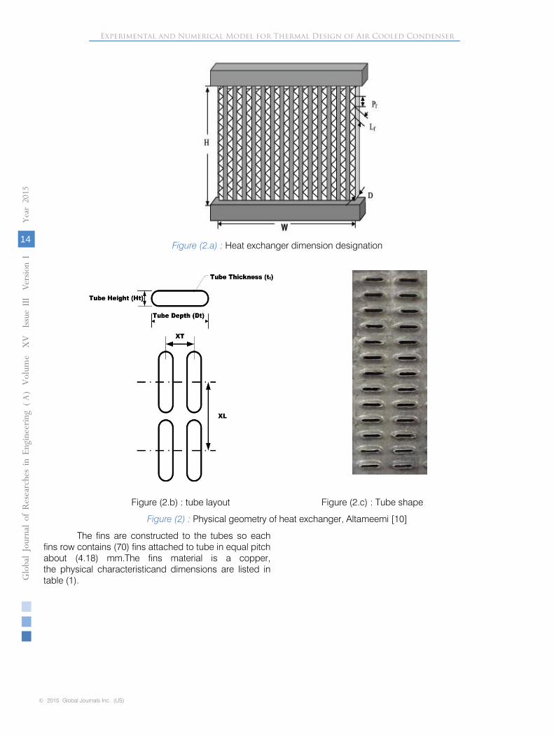
Figure (2.a) : Heat exchanger dimension designation
Figure (2.b) : tube layout Figure (2.c) : Tube shape
Figure (2) : Physical geometry of heat exchanger, Altameemi [10]
The fins are constructed to the tubes so each fins row contains (70) fins attached to tube in equal pitch about (4.18) mm.The fins material is a copper, the physical characteristicand dimensions are listed in table (1).
Globa
l Jo
urna
l of
Resea
rche
s in E
nginee
ring
()
Volum
Year
2015
14
Ae
XV
Issu
e III V
ersion
I
© 2015 Global Journals Inc. (US)
Experimental and Numerical Model for Thermal Design of Air Cooled Condenser
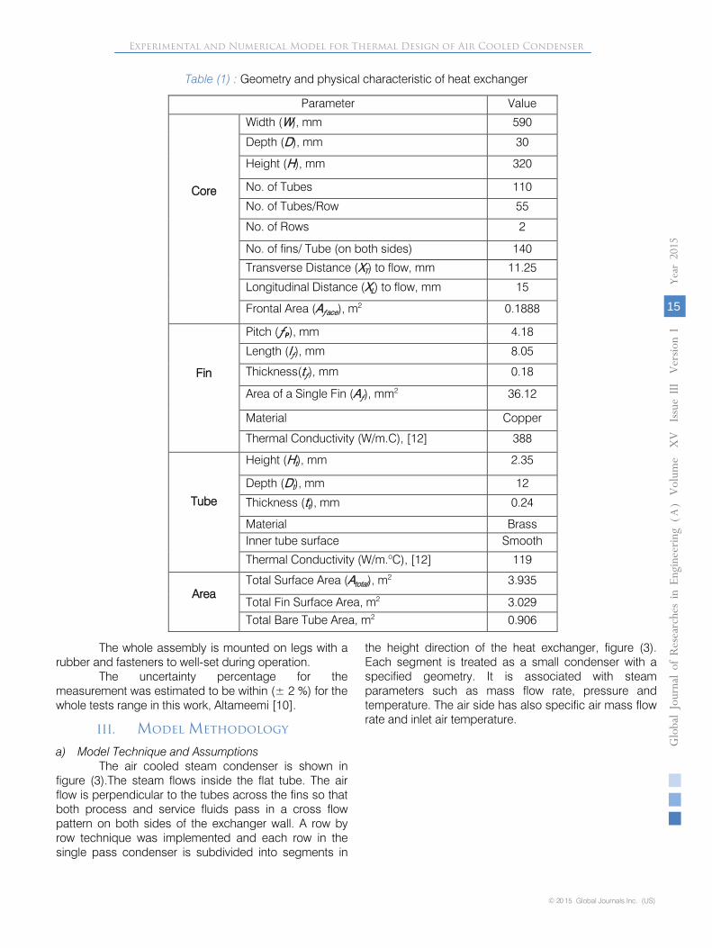
Table (1) : Geometry and physical characteristic of heat exchanger
© 20 15 Global Journals Inc. (US)
Globa
l Jo
urna
l of
Resea
rche
s in E
nginee
ring
()
Volum
e X
V
Issu
e III V
ersion
I
15
Year
2015
A
Experimental and Numerical Model for Thermal Design of Air Cooled Condenser
ValueParameter
590Width (W), mm
Core
30Depth (D), mm
320Height (H), mm
110No. of Tubes
55No. of Tubes/Row
2No. of Rows
140No. of fins/ Tube (on both sides)
11.25Transverse Distance (XT) to flow, mm
15Longitudinal Distance (XL) to flow, mm
0.1888Frontal Area (Aƒace), m2
4.18Pitch (ƒΡ), mm
Fin
8.05Length (lƒ), mm
0.18Thickness(tƒ), mm
36.12Area of a Single Fin (Aƒ), mm2
CopperMaterial
388Thermal Conductivity (W/m.C), [12]
2.35Height (Ht), mm
Tube
12Depth (Dt), mm
0.24Thickness (tt), mm
BrassMaterialSmoothInner tube surface
119Thermal Conductivity (W/m.oC), [12]
3.935Total Surface Area (Atotal), m2
Area3.029Total Fin Surface Area, m2
0.906Total Bare Tube Area, m2
The whole assembly is mounted on legs with a rubber and fasteners to well-set during operation.
The uncertainty percentage for the measurement was estimated to be within (± 2 %) for the whole tests range in this work, Altameemi [10].
III. Model Methodology
a) Model Technique and AssumptionsThe air cooled steam condenser is shown in
figure (3).The steam flows inside the flat tube. The air flow is perpendicular to the tubes across the fins so that both process and service fluids pass in a cross flow pattern on both sides of the exchanger wall. A row by row technique was implemented and each row in the single pass condenser is subdivided into segments in
the height direction of the heat exchanger, figure (3). Each segment is treated as a small condenser with a specified geometry. It is associated with steam parameters such as mass flow rate, pressure and temperature. The air side has also specific air mass flow rate and inlet air temperature.
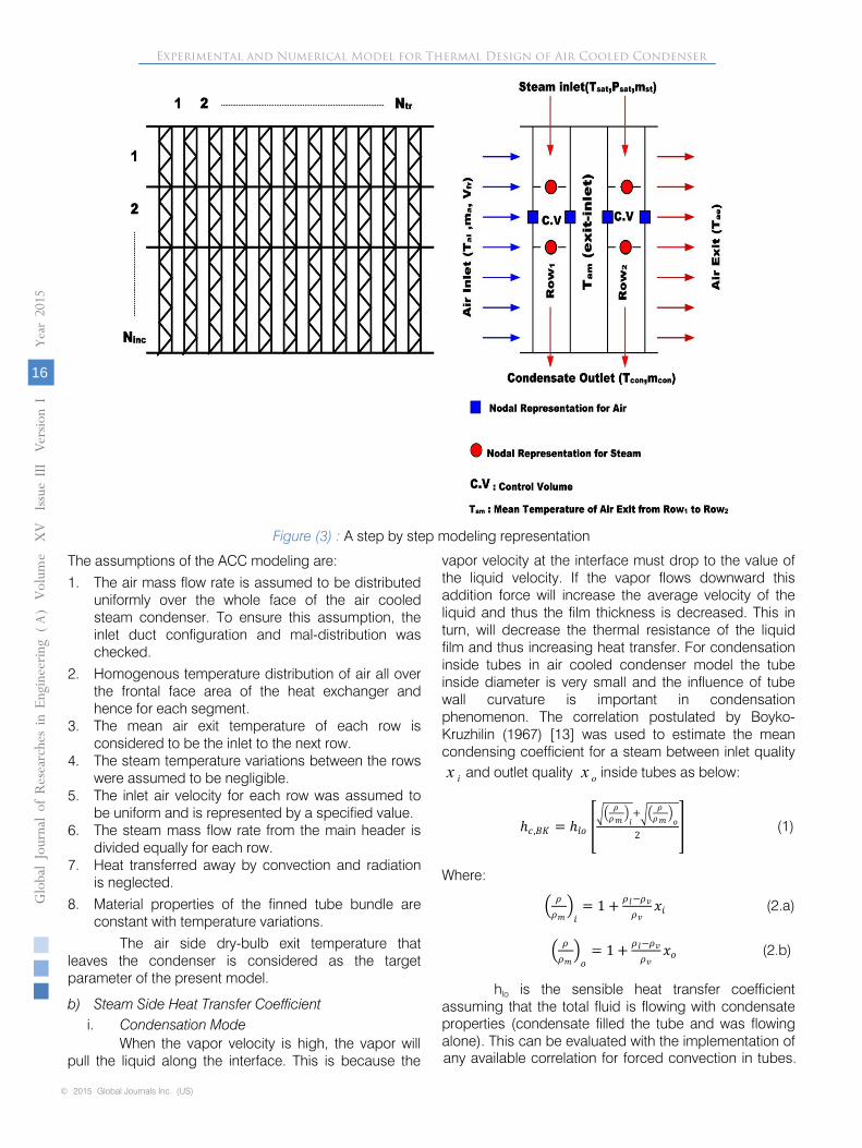
Figure (3) : A step by step modeling representation
The assumptions of the
ACC modeling are:
1.
The air mass flow rate is assumed to be distributed uniformly over the whole face of the air cooled steam condenser. To ensure this assumption, the inlet duct configuration and mal-distribution was checked.
2.
Homogenous temperature distribution of air all over the frontal face area of the heat exchanger and hence for each segment.
3.
The mean air exit temperature of each row is considered to be the inlet to the next row.
4.
The steam temperature variations between the rows were assumed to be negligible.
5.
The inlet air velocity for each row was assumed to be uniform and is represented by a specified value.
6.
The steam mass flow rate from the main header is divided equally for each row.
7.
Heat transferred away by convection and radiation is neglected.
8.
Material properties of the finned tube bundle are constant with temperature variations.
The air side dry-bulb exit temperature that leaves the condenser is considered as the target parameter of the present model.
b)
Steam Side Heat Transfer Coefficient i.
Condensation Mode
When the vapor velocity is high, the vapor will pull the liquid along the interface. This is because the
vapor velocity at the interface must drop to the value of the liquid velocity. If the vapor flows downward this addition force will increase
the average velocity of the liquid and thus the film thickness is decreased. This in turn, will decrease the thermal resistance of the liquid film and thus increasing heat transfer. For condensation inside tubes in air cooled condenser model the tube inside diameter is very small and the influence of tube wall curvature is important
in condensation phenomenon. The correlation postulated by Boyko-Kruzhilin (1967) [13] was used to estimate the mean condensing coefficient for a steam between inlet quality
and outlet quality inside tubes as below:
ℎ𝑐𝑐 ,𝐵𝐵𝐵𝐵 = ℎ𝑙𝑙𝑙𝑙 ���
𝜌𝜌𝜌𝜌𝑚𝑚
�𝑖𝑖+��
𝜌𝜌𝜌𝜌𝑚𝑚
�𝑙𝑙
2� (1)
Where:
� 𝜌𝜌
𝜌𝜌𝑚𝑚�𝑖𝑖
= 1 + 𝜌𝜌𝑙𝑙−𝜌𝜌𝑣𝑣𝜌𝜌𝑣𝑣
𝑥𝑥𝑖𝑖
(2.a)
� 𝜌𝜌𝜌𝜌𝑚𝑚�𝑙𝑙
= 1 + 𝜌𝜌𝑙𝑙−𝜌𝜌𝑣𝑣𝜌𝜌𝑣𝑣
𝑥𝑥𝑙𝑙 (2.b)
hlo
is the sensible heat transfer coefficient assuming that the total fluid is flowing with condensate
ix ox
Globa
l Jo
urna
l of
Resea
rche
s in E
nginee
ring
()
Volum
Year
2015
16
Ae
XV
Issu
e III V
ersion
I
© 2015 Global Journals Inc. (US)
Experimental and Numerical Model for Thermal Design of Air Cooled Condenser
properties (condensate filled the tube and was flowing alone). This can be evaluated with the implementation of any available correlation for forced convection in tubes.
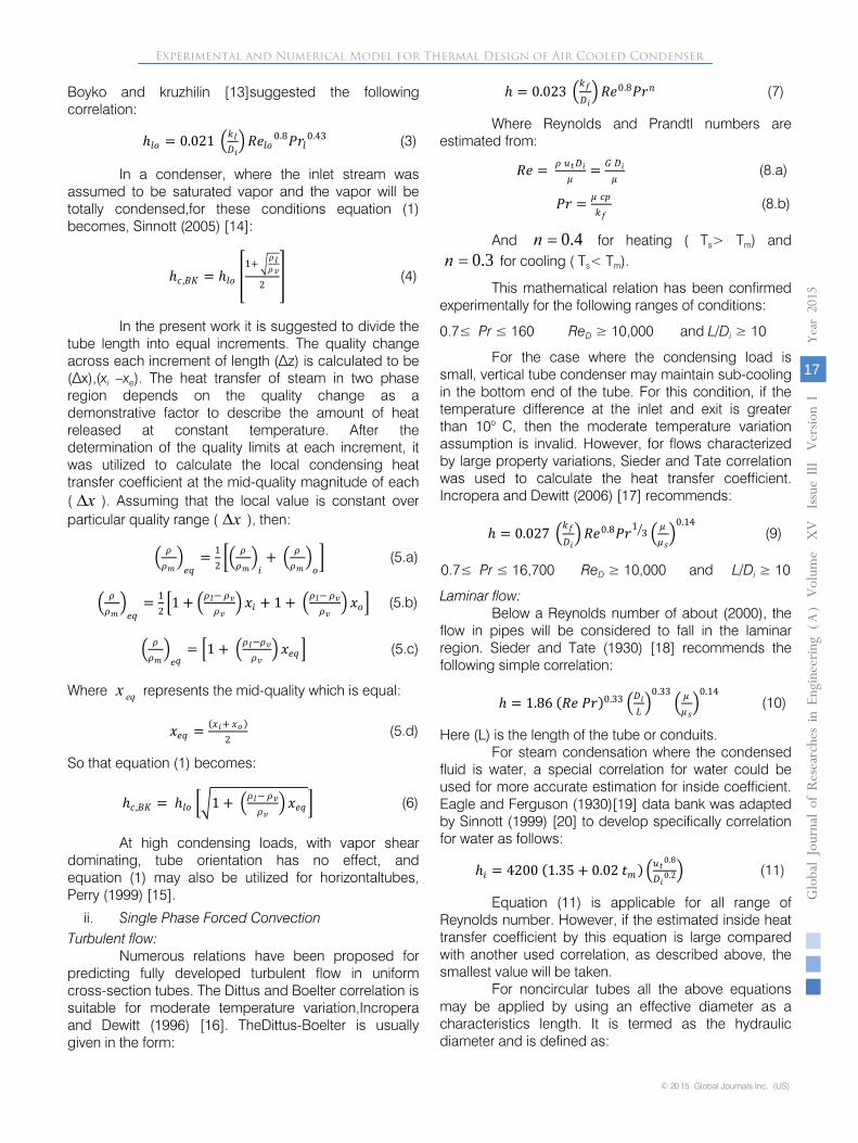
Boyko and kruzhilin [13]suggested the following correlation:
ℎ𝑙𝑙𝑙𝑙 = 0.021
�𝑘𝑘𝑙𝑙𝐷𝐷𝑖𝑖� 𝑅𝑅𝑅𝑅𝑙𝑙𝑙𝑙 0.8𝑃𝑃𝑃𝑃𝑙𝑙0.43 (3)
In a condenser, where the inlet stream was
assumed to be saturated vapor and the vapor will be totally condensed,for these conditions equation (1) becomes, Sinnott (2005) [14]:
ℎ𝑐𝑐 ,𝐵𝐵𝐵𝐵 = ℎ𝑙𝑙𝑙𝑙 �1+
�𝜌𝜌𝑙𝑙𝜌𝜌𝑣𝑣
2� (4)
In the present work it is suggested to divide the
tube length into equal increments. The quality change across each increment of length (∆z) is calculated to be (∆x),(xi –xe). The heat transfer of steam in two phase region depends on the quality change as a demonstrative factor to describe the amount of heat released
at constant temperature. After the determination of the quality limits at each increment, it was utilized to calculate the local condensing heat transfer coefficient at the mid-quality magnitude of each ( ). Assuming that the local value is constant over particular quality range ( ), then:
� 𝜌𝜌𝜌𝜌𝑚𝑚�𝑅𝑅𝑒𝑒
= 12�� 𝜌𝜌𝜌𝜌𝑚𝑚�𝑖𝑖
+ � 𝜌𝜌𝜌𝜌𝑚𝑚�𝑙𝑙� (5.a)
� 𝜌𝜌
𝜌𝜌𝑚𝑚�𝑅𝑅𝑒𝑒
= 12�1 + �𝜌𝜌𝑙𝑙−
𝜌𝜌𝑣𝑣𝜌𝜌𝑣𝑣
� 𝑥𝑥𝑖𝑖 + 1 + �𝜌𝜌𝑙𝑙−
𝜌𝜌𝑣𝑣𝜌𝜌𝑣𝑣
� 𝑥𝑥𝑙𝑙� (5.b)
� 𝜌𝜌
𝜌𝜌𝑚𝑚�𝑅𝑅𝑒𝑒
= �1 + �𝜌𝜌𝑙𝑙−𝜌𝜌𝑣𝑣
𝜌𝜌𝑣𝑣� 𝑥𝑥𝑅𝑅𝑒𝑒 � (5.c)
Where represents the mid-quality which is equal:
𝑥𝑥𝑅𝑅𝑒𝑒 = (𝑥𝑥𝑖𝑖+ 𝑥𝑥𝑙𝑙 )2
(5.d)
So that equation (1) becomes:
ℎ𝑐𝑐 ,𝐵𝐵𝐵𝐵 = ℎ𝑙𝑙𝑙𝑙 ��1 + �𝜌𝜌𝑙𝑙− 𝜌𝜌𝑣𝑣𝜌𝜌𝑣𝑣
� 𝑥𝑥𝑅𝑅𝑒𝑒 � (6)
At high condensing loads, with vapor shear dominating, tube orientation has no effect, and equation (1) may also be utilized for horizontaltubes, Perry (1999) [15].
ii. Single Phase Forced Convection
Turbulent flow: Numerous relations have been proposed for
predicting fully developed turbulent flow in uniform cross-section tubes. The Dittus and Boelter correlation is suitable for moderate temperature variation,Incropera and Dewitt (1996) [16]. TheDittus-Boelter is usually given in the form:
ℎ = 0.023 �𝑘𝑘𝑓𝑓𝐷𝐷𝑖𝑖� 𝑅𝑅𝑅𝑅0.8𝑃𝑃𝑃𝑃𝑛𝑛 (7)
Where Reynolds and Prandtl numbers are estimated from:
𝑅𝑅𝑅𝑅 = 𝜌𝜌 𝑢𝑢𝑡𝑡𝐷𝐷𝑖𝑖𝜇𝜇
= 𝐺𝐺 𝐷𝐷𝑖𝑖𝜇𝜇
(8.a)
𝑃𝑃𝑃𝑃 = 𝜇𝜇 𝑐𝑐𝑐𝑐𝑘𝑘𝑓𝑓
(8.b)
And for heating ( Ts> Tm) and for cooling ( Ts< Tm).
This mathematical relation has been confirmed experimentally for the following ranges of conditions:
0.7≤ Pr ≤ 160 ReD ≥ 10,000 and L/Di
≥ 10
For the case where the condensing load is small, vertical tube condenser may maintain sub-cooling in the bottom end of the tube. For this condition, if the temperature difference at the inlet and exit is greater than 10o C, then the moderate temperature variation assumption is invalid. However, for flows characterized by large property variations, Sieder and Tate correlation was used to calculate the heat transfer coefficient. Incropera and Dewitt (2006) [17] recommends:
ℎ = 0.027 �𝑘𝑘𝑓𝑓𝐷𝐷𝑖𝑖� 𝑅𝑅𝑅𝑅0.8𝑃𝑃𝑃𝑃1
3� � 𝜇𝜇𝜇𝜇𝑠𝑠�
0.14 (9)
Laminar flow: Below a Reynolds number of about (2000), the
flow in pipes will be considered to fall in the laminar region. Sieder and Tate (1930) [18] recommends the following simple correlation:
ℎ = 1.86 (𝑅𝑅𝑅𝑅 𝑃𝑃𝑃𝑃)0.33 �𝐷𝐷𝑖𝑖𝐿𝐿�
0.33� 𝜇𝜇𝜇𝜇𝑠𝑠�
0.14 (10)
Here (L) is the length of the tube or conduits. For steam condensation where the condensed
fluid is water, a special correlation for water could be used for more accurate estimation for inside coefficient. Eagle and Ferguson (1930)[19] data bank was adapted by Sinnott (1999) [20] to develop specifically correlation for water as follows:
ℎ𝑖𝑖 = 4200 (1.35 + 0.02 𝑡𝑡𝑚𝑚) �𝑢𝑢𝑡𝑡0.8
𝐷𝐷𝑖𝑖0.2� (11)
Equation (11) is applicable for all range of Reynolds number. However, if the estimated inside heat transfer coefficient by this equation is large compared with another used correlation, as described above, the smallest value will be taken.
For noncircular tubes all the above equations may be applied by using an effective diameter as a characteristics length. It is termed as the hydraulic diameter and is defined as:
x∆x∆
eqx
0.4n =0.3n =
© 20 15 Global Journals Inc. (US)
Globa
l Jo
urna
l of
Resea
rche
s in E
nginee
ring
()
Volum
e X
V
Issu
e III V
ersion
I
17
Year
2015
A
Experimental and Numerical Model for Thermal Design of Air Cooled Condenser
0.7≤ Pr ≤ 16,700 ReD ≥ 10,000 and L/Di ≥ 10
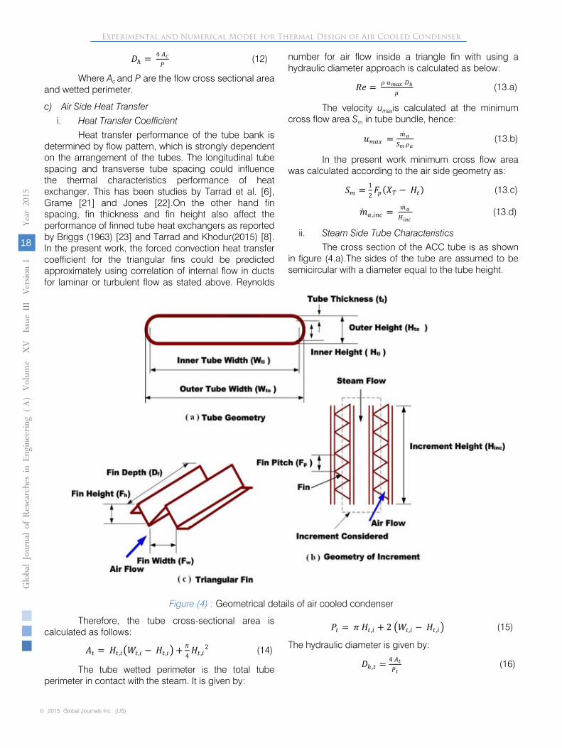
𝐷𝐷ℎ = 4 𝐴𝐴𝑐𝑐𝑃𝑃
(12)
Where Ac and P are the flow cross sectional area and wetted perimeter.
c) Air Side Heat Transfer i. Heat Transfer Coefficient
Heat transfer performance of the tube bank is determined by flow pattern, which is strongly dependent on the arrangement of the tubes. The longitudinal tube spacing and transverse tube spacing could influence the thermal characteristics performance of heat exchanger. This has been studies by Tarrad et al. [6], Grame [21] and Jones [22].On the other hand fin spacing, fin thickness and fin height also affect the performance of finned tube heat exchangers as reported by Briggs (1963) [23] and Tarrad and Khodur(2015) [8]. In the present work, the forced convection heat transfer coefficient for the triangular fins could be predicted approximately using correlation of internal flow in ducts for laminar or turbulent flow as stated above. Reynolds
number for air flow inside a triangle fin with using a hydraulic diameter approach is calculated as below:
𝑅𝑅𝑅𝑅 = 𝜌𝜌 𝑢𝑢𝑚𝑚𝑚𝑚𝑥𝑥 𝐷𝐷ℎ𝜇𝜇
(13.a)
The velocity umaxis calculated at the minimum cross flow area Sm in tube bundle, hence:
𝑢𝑢𝑚𝑚𝑚𝑚𝑥𝑥 = �̇�𝑚𝑚𝑚𝑆𝑆𝑚𝑚 𝜌𝜌𝑚𝑚
(13.b)
In the present work minimum cross flow area was calculated according to the air side geometry as:
𝑆𝑆𝑚𝑚 = 12𝐹𝐹𝑐𝑐(𝑋𝑋𝑇𝑇 − 𝐻𝐻𝑡𝑡) (13.c)
�̇�𝑚𝑚𝑚 ,𝑖𝑖𝑛𝑛𝑐𝑐 = �̇�𝑚𝑚𝑚𝐻𝐻𝑖𝑖𝑛𝑛𝑐𝑐
(13.d)
ii. Steam Side Tube Characteristics The cross section of the ACC tube is as shown
in figure (4.a).The sides of the tube are assumed to be semicircular with a diameter equal to the tube height.
Figure (4) : Geometrical details of air cooled condenser
Therefore, the tube cross-sectional area is calculated as follows:
𝐴𝐴𝑡𝑡 = 𝐻𝐻𝑡𝑡 ,𝑖𝑖�𝑊𝑊𝑡𝑡,𝑖𝑖 − 𝐻𝐻𝑡𝑡 ,𝑖𝑖� + 𝜋𝜋4𝐻𝐻𝑡𝑡 ,𝑖𝑖
2 (14)
The tube wetted perimeter is the total tube perimeter in contact with the steam. It is given by:
𝑃𝑃𝑡𝑡 = 𝜋𝜋 𝐻𝐻𝑡𝑡 ,𝑖𝑖 + 2 �𝑊𝑊𝑡𝑡,𝑖𝑖 − 𝐻𝐻𝑡𝑡 ,𝑖𝑖� (15)
The hydraulic diameter is given by:
𝐷𝐷ℎ ,𝑡𝑡 = 4 𝐴𝐴𝑡𝑡𝑃𝑃𝑡𝑡
(16)
Globa
l Jo
urna
l of
Resea
rche
s in E
nginee
ring
()
Volum
Year
2015
18
Ae
XV
Issu
e III V
ersion
I
© 2015 Global Journals Inc. (US)
Experimental and Numerical Model for Thermal Design of Air Cooled Condenser

The tube walls wetted by direct contact with steam transfer heat directly from the steam side to the outside air,hence the heat transfer area:
𝐴𝐴𝑠𝑠 = 2 �𝑊𝑊𝑡𝑡,𝑖𝑖 − 𝐻𝐻𝑡𝑡 ,𝑖𝑖�𝐿𝐿𝑡𝑡 + 𝜋𝜋 𝐻𝐻𝑡𝑡,𝑖𝑖𝐿𝐿𝑡𝑡 (17)
Each fin attached to the tube with approximately (1 mm) thickness along the depth. The contact area is calculated as:
𝐴𝐴𝑚𝑚𝑡𝑡𝑡𝑡 = 𝑡𝑡𝑚𝑚𝑡𝑡𝑡𝑡 𝐷𝐷𝑡𝑡𝑢𝑢𝑡𝑡𝑅𝑅 (18)
The total heat transfer area is given by:
𝐴𝐴𝑙𝑙 ,𝑡𝑡 = 𝐴𝐴𝑠𝑠 − 𝐴𝐴𝑚𝑚𝑡𝑡𝑡𝑡 (19)
iii. Air Side Tube Characteristics The cross section of the tube outer surface is
shown in figure (4.b). The face area of one tube and fin set in one increment, figure (4.c) is defined as:
𝐴𝐴𝑓𝑓𝑚𝑚 ,𝑖𝑖𝑛𝑛𝑐𝑐 = �𝐻𝐻𝑡𝑡𝑢𝑢𝑡𝑡𝑅𝑅 ,𝑙𝑙 + 𝐹𝐹ℎ�𝐻𝐻𝑖𝑖𝑛𝑛𝑐𝑐 (20)
Therefore, the area blocked by the fins is given by:
𝐴𝐴𝑡𝑡𝑚𝑚 = 𝐻𝐻𝑖𝑖𝑛𝑛𝑐𝑐𝐹𝐹𝑐𝑐
�𝑙𝑙𝑓𝑓𝑡𝑡𝑓𝑓 + 𝑙𝑙𝑓𝑓𝑡𝑡𝑓𝑓� (21)
The area available for air flow is represented as the total area less than the area blocked by the fins together with the area occupied by the tube for steam flow as follows:
𝐴𝐴𝑚𝑚 = 𝐴𝐴𝑓𝑓𝑚𝑚 ,𝑖𝑖𝑛𝑛𝑐𝑐 − �𝐴𝐴𝑡𝑡𝑚𝑚 + 𝐻𝐻𝑡𝑡𝑢𝑢𝑡𝑡𝑅𝑅 ,𝑙𝑙𝐻𝐻𝑖𝑖𝑛𝑛𝑐𝑐 � (22)
The perimeter of the tube which is directly in contact with air is given by:
𝑃𝑃𝑚𝑚 = �2 𝐻𝐻𝑖𝑖𝑛𝑛𝑐𝑐𝐹𝐹𝑐𝑐
�𝑙𝑙𝑓𝑓 − 𝑡𝑡𝑓𝑓� + �𝐻𝐻𝑖𝑖𝑛𝑛𝑐𝑐 − 𝐻𝐻𝑖𝑖𝑛𝑛𝑐𝑐𝑡𝑡𝑓𝑓𝐹𝐹𝑐𝑐�� (23)
The hydraulic diameter is:
𝐷𝐷ℎ ,𝑚𝑚 = 4 𝐴𝐴𝑚𝑚𝑃𝑃𝑚𝑚
(24)
The tube wall which is in contact with steam on the inside surface and with air on the outside surface directly transfers heat from the steam to the outside air. This constitutes the heat transfer area:
𝐴𝐴𝑚𝑚 ,𝑠𝑠 = �2 �𝐷𝐷𝑡𝑡,𝑙𝑙 − 𝐻𝐻𝑡𝑡 ,𝑙𝑙� �1 − 𝑡𝑡𝑓𝑓𝐹𝐹𝑐𝑐� + 𝜋𝜋 𝐻𝐻𝑡𝑡,𝑙𝑙�𝐻𝐻𝑖𝑖𝑛𝑛𝑐𝑐 (25)
The fins also confirm the heat transfer from the steam to air. Therefore fin surface area is defined as follows:
𝐴𝐴𝑓𝑓 ,𝑠𝑠 = 2 𝐻𝐻𝑖𝑖𝑛𝑛𝑐𝑐𝐹𝐹𝑐𝑐
�𝑙𝑙𝑓𝑓𝐷𝐷𝑓𝑓� (26)
The total heat transfer area become:
𝐴𝐴𝑙𝑙 = 𝐴𝐴𝑚𝑚 ,𝑠𝑠 + 𝜂𝜂𝑓𝑓𝐴𝐴𝑓𝑓 ,𝑠𝑠 (27)
Figure (5) : Representation of fin midpoint temperature variation
© 20 15 Global Journals Inc. (US)
Globa
l Jo
urna
l of
Resea
rche
s in E
nginee
ring
()
Volum
e X
V
Issu
e III V
ersion
I
19
Year
2015
A
Experimental and Numerical Model for Thermal Design of Air Cooled Condenser
Here ηf is the fin efficiency, when ( 0,dT x ldx
= = )
then the efficiency is given by, Kreith (1999) [24]. In the present work, the fin is represented by a schematic diagram shown in figure (5), hence:
𝜂𝜂𝑓𝑓 = tanh 𝑚𝑚𝑙𝑙𝑚𝑚𝑙𝑙
(28.a)
𝑚𝑚 = �ℎ𝑚𝑚𝑃𝑃𝑚𝑚𝑘𝑘𝑚𝑚𝐴𝐴𝑚𝑚
(28.b)
Therefore, the total surface efficiency of the fin, ηo is therefore expressed as below:
𝜂𝜂𝑙𝑙 = 1 −𝐴𝐴𝑓𝑓𝐴𝐴𝑙𝑙�1 − 𝜂𝜂𝑓𝑓� (29)

d) NTU Effectiveness Relations: The NTU method offers more advantages for
analyzing heat exchangers. It shows that iterative procedure is not required when inlet and outlet temperatures are unknown. For any heat exchanger, the total heat rejected from the hot fluid to the cold fluid is dependent on the heat exchanger effectiveness and also on the heat capacity of each fluid. This can be calculated as follows:
𝑄𝑄 = 𝜀𝜀 𝑐𝑐𝑚𝑚𝑖𝑖𝑛𝑛 �𝑇𝑇ℎ ,𝑖𝑖 − 𝑇𝑇𝑐𝑐 ,𝑖𝑖� (30.a)
The heat capacity, c, the extensive equivalent of the specific heat, determines the amount of heat a substance absorbs or rejects per unit temperature change, where:
𝑐𝑐 = �̇�𝑚 𝑐𝑐𝑐𝑐 (30.b)
The effectiveness is the ratio of the actual amount of heat transferred to the maximum possible amount of heat transferred and defined as:
𝜀𝜀 = 𝑄𝑄𝑄𝑄𝑚𝑚𝑚𝑚 𝑥𝑥
(31.a)
In the present work, the heat duty of each increment is calculated by the effectiveness-NTU method. The effectiveness relation for single-phase fluid cross flow is given below, Holman (2002) [25]:
𝜀𝜀 = 1 − 𝑅𝑅𝑥𝑥𝑐𝑐 �𝑅𝑅𝑥𝑥𝑐𝑐 (−𝑁𝑁 𝐶𝐶𝑃𝑃 𝑛𝑛)−1𝐶𝐶𝑃𝑃 𝑛𝑛
� (31.b)
And for Counter flow:
𝜀𝜀 = 1−𝑅𝑅𝑥𝑥𝑐𝑐 [−𝑁𝑁 (1−𝐶𝐶𝑃𝑃)]1− 𝐶𝐶𝑃𝑃 𝑅𝑅𝑥𝑥𝑐𝑐 [−𝑁𝑁 (1−𝐶𝐶𝑃𝑃)]
(32.a)
Where:
𝑛𝑛 = 𝑁𝑁−0.22 (32.b)
𝐶𝐶𝑃𝑃 = 𝑐𝑐𝑚𝑚𝑖𝑖𝑛𝑛𝑐𝑐𝑚𝑚𝑚𝑚𝑥𝑥
(32.c)
𝑁𝑁 = 𝑁𝑁𝑇𝑇𝑁𝑁 = 𝑁𝑁𝐴𝐴𝑐𝑐𝑚𝑚𝑖𝑖𝑛𝑛
(32.d)
This is the effectiveness relationship for a cross flow, single-pass heat exchanger with both fluid unmixed. For tow-phase fluid flow, the effectiveness relation is:
𝜀𝜀 = 1 − 𝑅𝑅𝑥𝑥𝑐𝑐(−𝑁𝑁𝑇𝑇𝑁𝑁) (33)
The overall heat transfer coefficient (U), takes into consideration the total thermal resistance to heat transfer between two fluids. Even though the convective heat transfer coefficients may be different on the two sides of the heat exchanger, the (UA) product is the same on either side. This is because all of heat taken from hot side must be transferred to the cold side. Overall heat transfer coefficient defined as,Sinnott (1999) [20]:
1𝑁𝑁𝑙𝑙
= 1ℎ𝑙𝑙𝜂𝜂𝑙𝑙
+ 1ℎ𝑓𝑓𝑙𝑙 ,𝑙𝑙𝜂𝜂𝑙𝑙
+𝐷𝐷𝑙𝑙 ln�𝐷𝐷𝑙𝑙𝐷𝐷𝑖𝑖
�
2 𝑘𝑘𝑤𝑤𝑚𝑚𝑙𝑙𝑙𝑙+ �𝐴𝐴𝑙𝑙
𝐴𝐴𝑖𝑖
1ℎ𝑓𝑓𝑙𝑙 𝑖𝑖𝜂𝜂𝑖𝑖
� + �𝐴𝐴𝑙𝑙𝐴𝐴𝑖𝑖
1ℎ𝑖𝑖𝜂𝜂𝑖𝑖
� (34.a)
By neglecting the effect of fouling on both sides of the heat exchanger, and inside surface efficiency, the overall heat transfer coefficient is reduced to:
1𝑁𝑁𝑙𝑙
= 1ℎ𝑙𝑙𝜂𝜂𝑙𝑙
+𝐷𝐷𝑙𝑙 ln�𝐷𝐷𝑙𝑙𝐷𝐷𝑖𝑖
�
2 𝑘𝑘𝑤𝑤𝑚𝑚𝑙𝑙𝑙𝑙+ �𝐴𝐴𝑙𝑙
𝐴𝐴𝑖𝑖
1ℎ𝑖𝑖� (34.b)
e)
Model Scheme The suggested model in the present work was
prepared in the form of a computer program designated as ACCRP. It was written with the aid of Liberty Basic Language, [26]. Multi iteration schemes were implemented to
obtain the final rating data of the air
cooled condenser. These were related to the air stream side and steam flow inside the tubes. A complete description and flow diagram of this code could be found in Altameemi [10].
IV.
Model
Verification
The experimental results are compared to the theoretical simulation results using the ACCRP
computer program. The results showed a good agreement with the experimental data.The present model was verified by the implementation of the
pressure. The model calculation scheme depends on the prediction of the air exit dry bulb temperature that on the lee side of the condenser under steady state conditions. Hence, this parameter was considered as an indication for the uncertainty percentage of the simulation process of the present model. Accordingly, the accuracy of the present row by row and step by step strategy is related to how far be the predicted air temperature and the condenser load from the experimental data. The uncertainty of each parameter and its discrepancy or scatter from the experimental data was estimated from:
Φ± =
Φ𝑡𝑡ℎ𝑅𝑅𝑙𝑙𝑃𝑃𝑅𝑅𝑡𝑡𝑖𝑖𝑐𝑐𝑚𝑚𝑙𝑙 −Φ𝑅𝑅𝑥𝑥𝑐𝑐𝑅𝑅𝑃𝑃𝑖𝑖𝑚𝑚𝑅𝑅𝑛𝑛𝑡𝑡𝑚𝑚𝑙𝑙Φ𝑅𝑅𝑥𝑥𝑐𝑐𝑅𝑅𝑃𝑃𝑖𝑖𝑚𝑚𝑅𝑅𝑛𝑛𝑡𝑡𝑚𝑚𝑙𝑙
(35)
Here Φ represents either the exit air temperature or the heat duty of the condenser.
a) Thermal Load The experimental data collected in the present
work showed its dependency on the air velocity and its temperature. Figure (6) shows the variation of the condenser load with entering temperature at two different velocities for a steam mass flow rate of (33.5) kg/hr. It is obvious that increasing air velocity or reducing the entering condenser air temperature will enhance the condenser load.Increasing the air velocity
Globa
l Jo
urna
l of
Resea
rche
s in E
nginee
ring
()
Volum
Year
2015
20
Ae
XV
Issu
e III V
ersion
I
© 2015 Global Journals Inc. (US)
Experimental and Numerical Model for Thermal Design of Air Cooled Condenser
,
experimental data collected from [10] at atmospheric
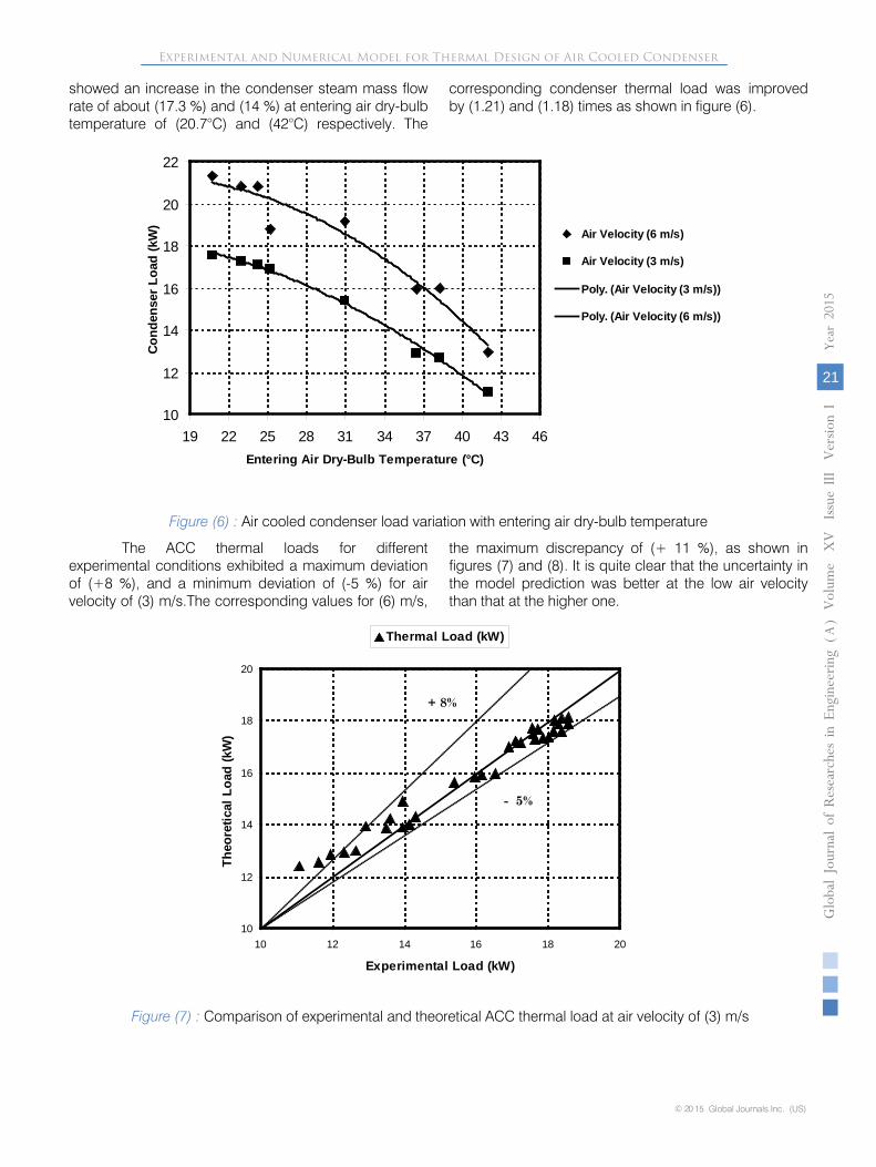
showed an increase in the condenser steam mass flow rate of about (17.3 %) and (14 %) at entering air dry-bulb temperature of (20.7°C) and (42°C) respectively. The
Figure (6) : Air cooled condenser load variation with entering air dry-bulb temperature
The ACC thermal loads for different experimental conditions exhibited a maximum deviation of (+8 %), and a minimum deviation of (-5 %) for air velocity of (3) m/s.The corresponding values for (6) m/s,
the maximum discrepancy of (+ 11 %), as shown in figures (7) and (8). It is quite clear that the uncertainty in the model prediction was better at the low air velocity than that at the higher one.
Figure (7) : Comparison of experimental and theoretical ACC thermal load at air velocity of (3) m/s
10
12
14
16
18
20
22
19 22 25 28 31 34 37 40 43 46Entering Air Dry-Bulb Temperature (°C)
Cond
ense
r Loa
d (k
W)
Air Velocity (6 m/s)
Air Velocity (3 m/s)
Poly. (Air Velocity (3 m/s))
Poly. (Air Velocity (6 m/s))
10
12
14
16
18
20
10 12 14 16 18 20
Experimental Load (kW)
Theo
retic
al L
oad
(kW
)
Thermal Load (kW)
- 5%
+ 8%
© 20 15 Global Journals Inc. (US)
Globa
l Jo
urna
l of
Resea
rche
s in E
nginee
ring
()
Volum
e X
V
Issu
e III V
ersion
I
21
Year
2015
A
Experimental and Numerical Model for Thermal Design of Air Cooled Condenser
corresponding condenser thermal load was improvedby (1.21) and (1.18) times as shown in figure (6).

Figure (8) : Comparison of experimental and theoretical ACC thermal load at air velocity of (6) m/s
Figure (9) shows the comparison between the measured experimental heat duty and that predicted by the present modal for the entire operating conditions considered in the present work. The model predicted the
condensation load with a high confidence and it lies with a scatter of (+12) % and (-5) % for more than (98) % of the data points.
Figure (9) : Comparison of experimental and theoretical ACC thermal load at air velocity of (3) m/s and (6) m/s
b) Exit Air Temperature Verification of the air exit temperature samples
for (3 and 6) m/s are shown in figure (10). It is obvious that all of the results are under predicted by (5 %). The
most attractive feature of the present model is its response to the variation of the operating conditions. These conditions are related to the condensation loading, air temperature and its flow rate.
10
12
14
16
18
20
22
24
10 12 14 16 18 20 22 24
Experimental Load (kW)
Theo
retic
al L
oad
(kW
)
Thermal Load (kW)
+ 11%
10
15
20
25
10 15 20 25
Experimental Load (kW)
Theo
retic
al L
oad
(kW
)
Thermal Load (kW)
+ 12%
-5%
Globa
l Jo
urna
l of
Resea
rche
s in E
nginee
ring
()
Volum
Year
2015
22
Ae
XV
Issu
e III V
ersion
I
© 2015 Global Journals Inc. (US)
Experimental and Numerical Model for Thermal Design of Air Cooled Condenser

Figure (10) : Comparison of experimental and theoretical ACC exit dry-bulb temperature for both test air velocities at different steam flow rates
c) Overall Heat Transfer Coefficient Distribution The distribution of the overall heat transfer
coefficient with the tube length is illustrated in figures (11),(12) for the ACC under low and high air velocity respectively. The present model showed that the local overall heat transfer coefficient for air cooled condenser varies with increment and row position in the air direction towards the exit side of the condenser. The variation with increment position is due to the condensation heat transfer variation with vapor fraction at each section. The variation with row position is due to the variation in air side heattransfer coefficient in the air direction.
It is obvious that the choice of increasing the air flow rate and flow velocities with (100%) by fanning a higher air volumetric flow may be considered to achieve high heat transfer. This is due to the increaseof air side heat transfer coefficient, especially for hot ambient condition when performance in a credible manner was required.The air velocity is an important character in air cooled condenser overall design and determination of the face velocity. However it is usually falls within the range of (1.5) to (4) m/s, Tarrad (2010) [7]. It is recommended for the face velocity of the air a value which is not exceeding (3) m/s, for pressure drop consideration, Wilber and Zammit (2005) [27].
30
35
40
45
50
55
60
65
70
30 35 40 45 50 55 60 65 70
Experimental Exit Temperature (°C)
Theo
retic
al E
xit T
empe
ratu
re (°
C)
Air Exit Temperature (°C)
- 5%
60
62
64
66
68
70
72
74
76
0 0.05 0.1 0.15 0.2 0.25 0.3 0.35
Tube Length (m)
Ove
rall
Heat
Tra
nsfe
r Coe
ffici
ent (
W/m
2.°C
)
Row 1Row 2
© 20 15 Global Journals Inc. (US)
Globa
l Jo
urna
l of
Resea
rche
s in E
nginee
ring
()
Volum
e X
V
Issu
e III V
ersion
I
23
Year
2015
A
Figure (11) : Overall heat transfer coefficient distribution for ACC under air flow velocity of (3) m/s at inlet air temperature of (31°C) and steam flow rate of (33.4) kg/hr
Experimental and Numerical Model for Thermal Design of Air Cooled Condenser
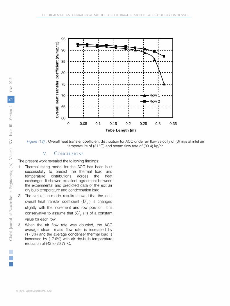
Figure (12) : Overall heat transfer coefficient distribution for ACC under air flow velocity of (6) m/s at inlet air temperature of (31 °C) and steam flow rate of (33.4) kg/hr
V. Conclusions
The present work revealed the following findings: 1. Thermal rating model for the ACC has been built
successfully to predict the thermal load and temperature distributions across the heat exchanger. It showed excellent agreement between the experimental and predicted data of the exit air dry bulb temperature and condensation load.
2. The simulation model results showed that the local overall heat transfer coefficient ( oU ) is changed
slightly with the increment and row position. It is conservative to assume that ( oU ) is of a constant
value for each row.3. When the air flow rate was doubled, the ACC
average steam mass flow rate is increased by (17.5%) and the average condenser thermal load is increased by (17.6%) with air dry-bulb temperature reduction of (42 to 20.7) °C.
60
65
70
75
80
85
90
95
0 0.05 0.1 0.15 0.2 0.25 0.3 0.35
Tube Length (m)
Ove
rall
Heat
Tra
nsfe
r Coe
ffici
ent (
W/m
2.°C
)
Row 1Row 2
Globa
l Jo
urna
l of
Resea
rche
s in E
nginee
ring
()
Volum
Year
2015
24
Ae
XV
Issu
e III V
ersion
I
© 2015 Global Journals Inc. (US)
Experimental and Numerical Model for Thermal Design of Air Cooled Condenser

© 20 15 Global Journals Inc. (US)
Globa
l Jo
urna
l of
Resea
rche
s in E
nginee
ring
()
Volum
e X
V
Issu
e III V
ersion
I
25
Year
2015
A
Experimental and Numerical Model for Thermal Design of Air Cooled Condenser
Nomenclature
A Area m 2
Cr Heat Capacity Ratio -cp Specific Heat at Constant Pressure J/kg.°CD Diameter or Depth mFp Fin Pitch mg Gravitational Acceleration m/s2
h Specific Enthalpy kJ/kghc Steam Condensing Heat Transfer Coefficient W/m2 °Cho Outside Heat Transfer Coefficient W/m2 °CH Height mk Thermal Conductivity W/m °CL Tube Length mlf Fin Length m
Fluid Mass Flow Rate kg/sn Parameter Defined by Equation (32.b), Correlation index -N Number -Nu Nusselt Number -p Operating Absolute Pressure of Steam barP Perimeter of Tube mPr Prandtle Number -
Condensation Load kWRe Reynolds Number -Sm Hollow Fin Cross Sectional Area m2
t Thickness mT Fluid Temperature °C or KT∆ Temperature Difference °Cu Fluid Velocity m/sUo Overall Heat Transfer Coefficient W/m2 °CW Air Cooled Condenser Width mxeq Steam Local Quality -XT Transverse Tube Pitch to the Flow Direction mXL Longitudinal Tube Pith in Flow Direction mz Heat Exchanger Cooled Length m
�̇�𝑚
�̇�𝑄
Greek Symbols
fη Fin Efficiency
oη Total Surface efficiency
ε Effectiveness of the Condenserρ Density (kg/m3)µ Viscosity (kg/m.s)Φ Parameter defined by eq. (35)Subscriptsa Airass. Assumed Valueatt. Attached c Condensate , coldcBK Boyko-Kruzhilin condensation coefficient cal. Calculated Valuecond Condenser, Condensatione Exit or Equivalenteff. Effectiveeq. Equivalent
est. Estimated Valuef Fouling , Fin or fluidg gash Hydraulic diameter, hot fluidi Inside or Inletinc incrementl Liquidlo Liquid Onlym meanmax maximummin minimumo Outside r ratio,rowrow Row Values Steam Value or Surfacet Tubetr tube per rowTube Tube Value ν Vapor w Wall Value
References Références Referencias
1. Kutscher C. and Costenaro D., "Assessment of Evaporative Cooling Enhancement Methods for Air- Cooled Geothermal Power Plants", presented at the Geothermal Resources Council, (GRC) ,Annual Meeting Reno, Nevada, September, (2002).
2. SaizJabarrdo, J.M., and Mamani,W.G.,"Modeling and Experimental Evaluation of Parallel Flow Micro Channel Condensers", J.Braz., Soc., Mech., Sci and Eng., Vol.25, No.2, Reo de Janeiro, Apr./June, 2003.
3. Gadhamshetty, V., Nirmalakhandan, N., Myint, M. and Ricketts, C.," Improving Air-Cooled Condenser Performance in Combined Cycle Power Plants", Journal of Energy Engineering, Vol.132,No.2,August 1, (2006).
4. Tarrad A. H., Shehhab U. S.,”The Prediction of Environment Effect on the Performance of a Vapour Compression Refrigeration System in Air Conditioning Application”, Journal of Engineering and Development. Vol.11, No.1, March 2007, pp.169-189.
5. Tarrad, A. H., Khudor, D. S., and Abdul Wahed, M.,” A Simplified Model for the Prediction of the Thermal Performance for Cross Flow Air Cooled Heat Exchangers with a New Air Side Thermal Correlation “, Journal of Engineering and Development, Vol. 12, No.3, 2008.
6. Tarrad, A. H., Saleh, F. A., and Abdulrasool, A.A., “A Simplified Numerical Model for a Flat Continuous Triangle Fins Air Cooled Heat Exchanger Using a Step by Step Technique”, Engineering and Development Journal, Vol. 13, No. 3, pp. 38-59, Al-Mustansiriya University, Baghdad, (2009).
7. Tarrad, A.H.,"A Numerical Model for Performance Prediction of Dry Cooling Conditions of Air Cooled Condensers in Thermal Power Plant Stations", Journal of Engineering and Technology, Vol.28, No.16, Baghdad, Iraq, (2010).
8. Tarrad, A. H. and Khudor, D. S., “A Correlation for the Air Side Heat Transfer Coefficient Assessment in Continuous Flat Plate Finned Heat Exchangers”,
10. Altameemi, A. F., “Study and evaluation of the operation characteristics for the condensation load
distribution in hybrid systems on the condenser side”, MSc. Thesis, Al-Mustansiriya University, Baghdad, June 2011.
11. Jana, W.S.,"Engineering Heat Transfer", 2nd edition, CRC press, LLc, USA, 2000.
12. Jung D., D., and N. Assanis," Numerical Modeling of Cross Flow Compact Heat Exchanger with Louvered Fins using Thermal Resistance Concept", SAE. Paper, 2006-01-0726, University of Michigan, (2006).
13. Boyko-Kruzhilin, "Heat Mass Transfer", Inc. J., Vol.10, pp. 361, 1967.
14. Sinnott, R.K.,Chemical Engineering, Vol.6, Heaton, A.W. and Co. LTD, Exeter, (2005).
15. Robert, H.P. and Green, D.W.,"Perry's Chemical Engineering Hand Book ", 8th Edition, McGraw-Hill Company, New York, (1999).
16. Incropera, F. P. and DeWitt, D. P., "Fundamentals of Heat and Mass Transfer", 4th Edition, John Wiley & Sons, New York, (1996).
17. Incropera, F. P. and DeWitt, D. P., "Fundamentals of Heat and Mass Transfer", 6th Edition, John Wiley & Sons, New York, (2006).
18. Sieder, E.N., and Tate, C.E.," Heat Transfer and Pressure Drop of Liquids in Tubes", Ind. Eng. Chem., Vol.28, p.1429, 1936.
19. Eagle, A., and Freguson, R.M.," On the coefficient of Heat Transfer from the Internal Surface of Tube Walls", Proc.R. Soc. Lond. A June 2, 1930.
20. Sinnott, R.K.,Chemical Engineering, Vol.6, Heaton, A.W. and Co. LTD, Exeter, (1999).
21. Gram, A.J., Mackey, C.O., and Monroe, E.S. Jr., "Convective Heat Transfer Banks, II- Correlation of Data for Tem Row Deep Tube Bank", ASME Trans., Vol.80, p.25, 1958.
22. Jones, C.E., and Monroe, E.S. Jr.," Convective Heat Transfer and Pressure Drop of Air Flowing across In-Line Tube Banks, I- Apparatus, Procedure and Special Effects", ASME Trans., Vol.80, p.18, 1958.
23. Briggs, D.E., and Young, E.H.," Convective Heat Transfer and Pressure Drop of Air Flowing across Triangular Pitch Banks of Finned Tubes", Chem. Eng. Progress Symposium Series- Heat Transfer, Vol.59, No.41, pp.1-10, 1963.
24. Kreith, F., "Thermal Engineering", CRC press, LLc, USA, 1999.
Globa
l Jo
urna
l of
Resea
rche
s in E
nginee
ring
()
Volum
Year
2015
26
Ae
XV
Issu
e III V
ersion
I
© 2015 Global Journals Inc. (US)
Transactions of the ASME, Journal of Thermal Science and Application, Vol. (7), No. 2, Paper No. TSEA-14-1194, DOI: 10.11151/1.4029459, 2015.
9. Tarrad, A. H. and Al-Nadawi, A. K., “A Rating Model of Finned-Tube Condenser using Pure and Zeotropic Blend Refrigerants”, accepted for publication in German Journal of Mechanical Engineering Research, 2015.
25. Holman, J. P., "Heat Transfer", 9th Edition, McGraw-Hill Book Company, (2002).
26. Liberty Basic Program, V4.04, Modern Basic Language to Produce Custom Windows Programs, available from World Wide Web: www.libertybasic.com .
27. Wilber,K. R. and Zammit, K.,"Development of Procurement Guidelines for Air-Cooled Condensers", CEC/EPRI, Advanced Cooling Strategies/Technologies Conference, Sacramento, California, (2005).
Experimental and Numerical Model for Thermal Design of Air Cooled Condenser
ACC Air Cooled Condenser ACCRP Air Cooled Condenser Rating ProgramNTU Number of Heat Transfer UnitOHTC Overall Heat Transfer Coefficient
Abbreviations