experimental campaign tests on ultra micro gas turbines
TRANSCRIPT

energies
Article
Experimental Campaign Tests on Ultra Micro GasTurbines Fuel Supply Comparison and Optimization
Roberto Capata and Matteo Saracchini
Department of Mechanical and Aerospace Engineering University of Roma ldquoSapienzardquo 00184 Roma Italymsaracchinigmailcom Correspondence robertocapatauniroma1it Tel +39-064-458-5243 Fax +39-064-458-5850
Received 1 March 2018 Accepted 20 March 2018 Published 30 March 2018
Abstract The increasing demand for miniaturized radio-controlled vehicles inspired the followingresearch The uses of these unmanned miniaturizedmicro vehicles range from aero-modeling todrones for urban control and military applications too The common characteristic of these vehiclesis the need for a light and compact propulsion system The radio-controlled (RC) turbines formodeling are ideally suited for this purpose guaranteeing the necessary thrust with compactnessand lightness This device is a miniaturized turbojet and it is generally composed of three basicelements compressor combustion chamber and turbine The main goal of the paper is to evaluatethe turbojet performance for considering the possibility of its use as a range extender in a hybridvehicle Considering the total volume constraints it will be important to evaluate the specific fuelconsumption Also from the environmental point of view the possibility of feeding the device withgas has been considered and consequently the needed device modifications performed The testbench has been realized and assembled at the University Department Laboratory Several differentexperimental configurations are reproduced and reported here to obtain performance mapsThe experiments results have been compared to previous tests results as well as numericalsimulations Therefore it has been possible to make a comparison between the two differentfuels The results show that this device can be used as a range extender for a hybrid vehicleMoreover the various tests have shown that acting on the control unit it is possible to feed the devicewith gas (mixture of propane and butane) obtaining a further benefit from the economic point ofview Surely an in-depth study of the turbine management logic would produce a further advantagein terms of fuel consumption
Keywords experimental tests micro turbine fuel consumption
1 Introduction
In the early design stages an (approximately) correct prediction of the performance of aturbomachine is critical not only because it ensures that the type of components of the stage(impeller diffuser and volute) are in line with current technology and with the design specificationsbut also because it facilitates the subsequent final design task The general performance maps availablefrom manufacturers are usually limited to a small range of rotational speeds pressure ratios andmass flow rates and extrapolating on their basis at the onset of a selection or design task is especiallyrisky Current portable power generators are mainly based on internal combustion engines (ICEs)since they present higher values of efficiency compared to other engines the main reason why ICEsare not convenient for micro power generation (5ndash30 kW) is because of their heaviness Micro- andUltra-Micro Gas Turbine (UMGT) devices based on a micro compressor and a micro turbine installedon the same shaft are more suitable for this scope for several reasons They present a higher powerdensity both in terms of kWkg and kWm3 lower emissions less moving elements multi-fuel
Energies 2018 11 799 doi103390en11040799 wwwmdpicomjournalenergies
Energies 2018 11 799 2 of 17
capability (they operate almost equally well with kerosene natural gases propane etc) The mainreason why UMGTs are not currently realized is due to their low efficiency In fact while todaylarge-scale commercial turbo-gas power plants reach the 40 mark micro turbo-sets rarely exceed15 Low efficiency on such an engine is related to the high velocity the fluid has inside the turbomachinery channels which lower the efficiency of the compressor and the turbine and the combustionprocess The actual device is a single-stage radial compressor (C) and an axial turbine (T) The smalldimensions of the turbo machinery lead to a very high rotational speed which places severe demandson the bearings
In addition it can be remembered that the main problem of power conversion based on miniatureturbomachinery is the lack of suitable performance data for such small-scale equipment The describedand presented tests could contribute to the advancement of compressorturbine performance at smallscale (lt50 kW) and supply a valid help to design a highly efficient and robust power conversiontechnology Since 1980 [12] several tests at a small scale has been carried out In 2000 and 2001 [34]the first results have been published for a 4 mm diameter turbine with prismatic blades reaching1400000 rpm and an output power of 5 W In 2003 and 2004 [56] the articles give an overview of the10 W Massachusetts Institute of Technology (MIT) micro-gas turbine project In 2005 the feasibilitystudy of a gas turbine engine with an output of 100 W using 3D radial impellers operating at apressure ratio of 3 requiring rotational speeds in excess of 850000 rpm has been presented In 2006Japanese researchers [7] demonstrated the feasibility of a radial compressor rotating at 720000 rpmreaching pressure ratios up to 2 and isentropic efficiencies in excess of 60 This brief collection ofresearch works clearly demonstrates the technical feasibility of such a devices but at the same timethe lack of a detailed collection of experimental tests Analizing the small-scale turbomachinery such amachinery is affect by low Reynolds-number flows a large relative tip clearance and a non-adiabaticflow condition
The effect of low Reynolds-number flows in the compressor stages has been thoroughly capturedin early work [6ndash8] where a correction based on the machine Re-number and surface roughnesswas proposed Since the early works by Wiesner and Stodola and Lowestein one-dimensionalprediction techniques and related semi-empirical loss correlations have been persistently developedThe prevailing approach is to lump together losses of different type in the form of either a slip factora loss coefficient or both The downside of such a model is that the effects of individual losses are notclearly characterized and some phenomenological information is lost To validate the results someauthors try to provide a combination of computational fluid dynamics (CFD) analysis and experimentaltests [89] Tip clearance has been investigated by various teams [10ndash13] all claiming that a 10 increasein tip clearance decreases performance by 3ndash4 points Recent work however shows that this trendmay be considerably smaller or even larger depending on the impeller geometry and suggests thatso far no clear correlation was found [1415] All these considerations have suggested to carry out acampaign of tests on a small-scale gas turbine device to fill those gaps previously described in thisparagraph The tested device was a group for aero modelling [16] The knowledge of the performanceof the system has been dictated by project program in which this campaign has been carried out In theframework of this research (Italian Research Program-project to build a high-performance GT devicefor vehicular application) it needed to find the ldquoquasi-optimalrdquo propulsion device and therefore theanalysis of selected group becomes of fundamental importance
In the following paragraphs an in-depth analysis of the gas turbine device components will bepresented as well as the test bench assembly Then in the methodology section the experimentalcampaigns carried out with kerosene and gas will be illustrated The obtained experimental datawere then integrated through thermodynamic numerical simulations to obtain a reasonable previewregarding the net output power and an estimation of the cost of the KW produced
Energies 2018 11 799 3 of 17
2 Turbojet Configuration
The turbojet engine used for the experimental campaign is a Jetcatreg P60 SE (Ingenieurbuumlro CATDottingen Germany) whose technical characteristics are listed in Table 1
Table 1 Device operational specifications
Max Thrust 56 N at 165000 RPM
Weight 845 gr incl StarterDiameter 83 mmRPM Range 50000ndash165000Exhaust gas temp 580 Cndash690 C
With reference to the Figure 1 (turbine cut-away) it is possible to identify its main components(1) electric motor (EM) (2) compressor (C) (3) combustion chamber (CC) (4) turbine (5) nozzle and(6) thermocouple housing
Figure 1 Jetcat P60 SE
In details
(1) This electric motor initializes the shaft rotation When the RPM reach a pre-set value(flame stabilization) the starter motor is switched off and the turbine drives the deviceDuring the operating mode the electric motor is used by a generator (DC) delivering an electricalsignal to control unit (ECU) The signal is proportional to rotation speed (the device operates as atachometer) Finally in the shutdown procedure the electric motor is switched on and operate asa cooling member as long as the temperature does not drop to 100 C
The EM is coupled with the crankshaft by the compressor screw nut(2) The compressor is single-stage radial centered on the crankshaft The stator blades are aluminum
made that guarantees resistance and lightness On this side the fuel distribution system isrealized and constitutes the front cover of turbine (baseplate) A ceramic bearing allow thecompressor blade alignment with the shaft Such a compressor has been previously tested [17]and all maps constructed In any case the compressor operation maps will be reported hereafter
(3) The combustion chamber is obtained from a laser welded steel cylinder The fuel distributionO-ring is manufactured on the baseplate The parts correctly aligned are assembled in a metalstand The fuel delivery is obtained by a system of pipes that enter into the chamber The mixtureis ignited by an electronically controlled spark plug
(4) The stator vane are pressed on the end of the chamber will redirect the flow of hot gasses to theturbine wheel The axial turbine wheel and the shaft are install into the turbojet sliding the shaft
Energies 2018 11 799 4 of 17
into the centre cylinder The rotation induced to the turbine turns the compressor feeding theprocess Finally the turbine outlet gases come into the nozzle (5) maximizing the thrust
(5) A nozzle is placed at the turbine outlet to maximize thrust(6) A thermocouple is placed on the turbine side (ends in the nozzle) for measuring the outlet
exhausted gas temperature
3 Device Electronics
The ECU (Figure 2) is a microcomputer that manages the ignition phase controls the fuel solenoidvalves the kerosene pump and in case of radio-commanded vehicle mounting decodes the flightinformation The Ground Support Unit (GSU) is the turbine control and maintenance system directlyconnected to the ECU Through the backlit alphanumeric display and 10 operational keys (Figure 3)it is possible to monitor all ECU functions and change some parameters The monitored functions are
(1) exhaust gas temperature(2) number of revolutionsrpm(3) pump voltage(4) battery voltage
The monitored and measured data are
(1) total fuel consumption(2) total operation time(3) maximum speed(4) number of unsuccessful and failed starts(5) partial load time
Figure 2 Electronic connection
Energies 2018 11 799 5 of 17
Figure 3 The Ground Support Unit (GSU)
4 Test Bench Assembling
Test bench assembly has been created as follows firstly the hydraulic circuit for the fuel supplyhas been connected then the electrical circuit for the regulation and control of the machine have beenrealized Finally the whole measuring chain for these devices has been realized
41 Hydraulic Circuit
The JetCat engine can use deodorized kerosene 1-K kerosene or Jet-A1 as fuel Fuel must bemixed with 5 synthetic turbine oil to ensure lubrification JetCat itself recommends Aeroshell 500turbine oil although any turbine oil that conforms to MS23699 standards can be used [16] The inputand output fuel piping must be connected to the electronic shut-off valve When the engine runs at fullpower the control unit ECU checks the fuel line from the pump to the engine The hydraulic systemconsists of the following components (Figure 4)
Figure 4 Fuel supply systems
Energies 2018 11 799 6 of 17
(1) Five (5) liter tank(2) Filter(3) Electric pump (with its cables connected to the ECU)(4) Solenoid valve (with its cables connected to the ECU)(5) 4 mm diameter tubes
42 Gas Circuit
In Figure 5 shows the fuel supply systems using a mixture of propane and butane gasThis configuration is used only for the start-up procedure As can be noticed the gas pipes areconnected to the electronic shut-off valve The gas starter tank can be mounted vertically or horizontallyIf the tank is mounted in the vertical or lateral position the offset nipple is positioned upward In thisway the amount of liquid propane that enters the turbine during startup is limited and adjustedAfter each test session the valve must be open to empty the tank The propane filter is installed justbefore the starter gas valve
Figure 5 Gas supply systems
5 Experimental Campaigns
The experimental campaigns have been carried out in the department laboratory The assembledtest bench is shown in Figure 6 Once the turbine is switched on and the operating point hasbeen reached the measurement campaign started acquiring data from the speed of 50000 rpmThe incremental step was 5000 rpm for each subsequent test The test time was approximately 5 minfor each ldquomeasuring stationrdquo for a total of 7 h 23 m 36 s The tests have been repeated 10 timesThe same test procedure described in the following paragraphs was adopted for all specific tests
Figure 6 Assembled test bench
Energies 2018 11 799 7 of 17
51 ldquoKerosenerdquo Experimental Campaign
As previously described the data measured were
bull fuel consumption using software supplied by the manufacturer calibrated on the electric pumpvoltage [(10 mLmin divide 250 mLmin) plusmn05 mLmin]
bull exhaust gas temperaturebull inlet mass flow rate
For these tests the bench was set up with manifold with the anemometer on the turbojet frontThe instruments used are described below
(1) NiCr-CuNi thermocouple (IEC 60584-11) [minus20 divide 800 C] plusmn15 C(2) Anemometer for measuring the velocity of air in the intake collector [0 divide 30 ms] accuracy plusmn3
Test procedure is show in the Figure 7 which summarizes in a schematic way the actionsperformed to obtain the experimental data
Figure 7 Experimental procedure
The waiting time of 3 min before acquiring the data ensures that the engine operates at constantspeed since no significant fluctuations (plusmn1) of the operating parameters have been recorded
The experiment environmental conditions are
bull Tamb = 34 Cbull Relative humidity (RH) = 57bull pamb = 101300 Pa
The ambient temperature albeit high did not significantly affect the tests from the feedbackobtained on previous experimental campaigns carried out at an ambient temperature of about 25 CThis property of the turbojet is undoubtedly attributable to its destination for aeronautical use
Energies 2018 11 799 8 of 17
By analyzing fuel consumption there is an increasing linear trend The increase of turbinerevolutions increases fuel consumption In the maximum overall performance conditions (165000 rpm)the fuel consumption value is 161 mLmin By studying the trend of the inlet compressor mass flowrate it can be notice that it is linear too reaching the maximum value of 021 kgs at 165000 rpm
Finally with regard to the exhausted gases temperature (EGT) it appears to have a variabletrend The trend of EGT is the result of the following conditions during the ignition phase themixture introduced into the combustion chamber results to be in rich mixture conditions (more fuel)The amount of fuel in excess is necessary to establish and stabilize the combustion This extra quantity(compared to the stoichiometric conditions) produces an initial increase in temperature Once thecombustions is stabilized and the self-sustaining speed has been reached (for this device 50000 rpm)the control unit controls and reduces the entry of fuel to bring it back almost to stoichiometricconditions As a result the temperature decreases (testified from the concave trend of EGT in diagram)
Finally when the operator decides to increase the rotation speed by acting on the controls(the throttle is adjusted on the software) there is a consequent increase of fuel in the combustionchamber which produces a corresponding increase in temperature This is the reason for the progressof the EGT that the software reports which is shown in the Figure 8b
Figure 8 Cont
Energies 2018 11 799 9 of 17
Figure 8 (a) fuel consumption (b) exhaust gas temperature (EGT) (c) air mass flow rate
52 Gas Experimental Campaign
The second test campaign has been dictated by the need to check whether the device could onlybe powered by gas For this goal some changes were necessary It is to be remembered that the gascircuit is used to start the engine In order to achieve the constant use of gas as fuel the followingchanges have been required
(1) Modification of the electronics and layout of the system(2) Any necessary adjustments(3) Lubrication
Since the system was not designed for gas operation it was necessary to remove the gas solenoidvalve block This valve is closed once the boot procedure has finished The ECU module was thenreprogrammed disabling the automatic closing of the solenoid valve In addition it was mountedan additional gas tank (6 L) necessary to withstand the combustion The valve control has beenmanually obtained The capacity valve shown in the figure has been used By acting on it the gas flowrate can be increased or decreased in the combustion chamber and thus the rotational speed of theturbine The problem of lubrication has been solved for the studied prototype using a bypass systemThe system allows to alternatively operate with kerosene (+5 oil) and gas
The procedure is as follows by manually acting on the valves it is possible to operate thegas turbine for the necessary time to obtain experimental data of interest Then by switchingthe valve and using kerosene as fuel it was possible to lubricate the entire device Iterating thisprocedure operational maps have been obtained compatible with those obtained using keroseneas fuel An additional benefit that has been achieved by acting in this way the bearings have notbeen damaged Two ball valves (marked with 1 and 2 in the figure) have been used for this systemThe assembled system is shown in Figure 9
To perform gas tests it was necessary change the bench configuration because the turbojet is notpredisposed to operation with only gas for the following changes have been used
bull 2 times 4 mm ball valve for manage the flow of kerosene +5 oil to ensure lubricationbull 1 times 4 mm gas flow calibrated regulator coupled with a mass flowmeter (plusmn08 of reading value
default response time of 10 ms) to control the acceleration and fuel consumptionbull 1 times 4 mm Y connectorbull 1 times 4 mm T connector
Energies 2018 11 799 10 of 17
The ECU has been reprogrammed using the software LCU Pro to disable valve safety locksThe test procedure is as follows
(1) Connect the gas tank to the inlet connector for the start procedure(2) Fill kerosene tank(3) Connect the main gas tank(4) Connect the ECU to PC(5) Enable virtual radio control(6) Start the turbojet by pushing the virtual start button(7) Valve 2 is CLOSE and Valve1 is OPEN act on Valve 3 until it reaches RPM target value(8) Note the gas consumption after 3 min of operation at fixed RPM(9) Close Valve 3 open Valve 2 and close Valve1 to let kerosene flow into the turbojet lubricating
the bearings for 3 min(10) Repeat (7) (8) and (9) for each 5000 rpm step
Given that the compressor air flow is the same as for kerosene operation being the samecompressor the fuel consumption (the target of the research) has been reported (Figure 10) with theEGT trend Also in this case for each step of 5000 rpm within 50000ndash165000 rpm range It appears tohave an average linear ascending trend from the minimum value of 078 gs to 50000 rpm up to amaximum of 218 gs at 165000 rpm
Figure 9 Gas circuit modification
Figure 10 Cont
Energies 2018 11 799 11 of 17
Figure 10 (a) Gas consumption (b) Exhaust Gas Temperature
6 Data Analysis and Thermodynamic Considerations
To completely understand the device operational design values (and to connect the resultsto a well-specific machine) a reverse design was carried out comparing it with experimentaldata previously performed on similar devices [1819] and with the data collected in this series oftests The intent is to know all basic parameters and compare them with the experimental onesFurthermore the possibility of operating the device as an electrical generator has also been studiedThe design procedure was as follows Starting from the compressor analysis the geometric parametersare shown in Table 2 and Figure 11
Table 2 Geometrical specifications
d1s 0038 m
d1h 0013 md2 005 mb2 0004 mszlig2 35
blades 10
Figure 11 Reference impeller scheme
With the available data velocity triangles have been calculated for Sections 1 and 2 For theinlet section
U1 = ωd1m
2(1)
Energies 2018 11 799 12 of 17
and assuming V1 = V1m
V1 =QinAin
(2)
Once V1 and U1 are known the relative velocity W1 is
W1 =radic
U12 +V1
2 (3)
For Section 2U2 = ω
d2
2(4)
Assuming V1 = V1m = V2m the flow coefficient and load coefficient are
ϕ2 =V2m
U2(5)
ψ2 = 1 minus ϕ2
tan szlig2(6)
so the velocity V2 and W2 are
V2 =
radic(ψ2U2)
2 +V2m2 (7)
W2 =
radic(U2(1 minusψ2))
2 +V2m2 (8)
Note the velocity triangles the rotor work (L) has been calculated as
L =U2
2 minus U12
2+
V22 minus V1
2
2+
W12 minus W2
2
2(9)
and in first approximation knowing the R$ asymp 1 minus ψ22 the total compressor work
(Lcomp
)was
calculated and used to find the compression ratio
βcomp =
[Lcomp
middotmair(k minus 1)
Qair patmk
] kkminus1ηpol
(10)
where the polytopical efficiency was calculated with a modified Stodola formula [15] Finally theoutlet compression temperature and pressure (T3 and p3) have been calculated
T3 = Tamb βcompkminus1
k (11)
p3 = pamb βcomp (12)
Regarding the turbine note the EGT has been calculated the starting expansion temperature (T4)and the heat released by the combustion (Q)
Q =middot
m f uel LHV ηcc (ηcc = 08) (13)
For the calculation of the βexp it is preferred not to structurally change the turbojet architecturetherefore no pressure gauges have been inserted into the combustion chamber Instead this hasbeen done by estimating the load losses in the combustion chamber in ldquocoldrdquo configuration andthen extending the data throughout the operating field assuming an overall error of 47 [2021]This choice is preferred to safeguard the structural integrity of the turbojet while still obtaining datasuitable for calculating the net work (Figure 12)
This has allowed us to find a ∆β = 536 divide 203 so the values of βexp and the p4
Energies 2018 11 799 13 of 17
It was then possible to calculate the work of turbine (Lturb) as
Lturb =k
k minus 1p4
ρ4
(βexp
kminus1k ηpol minus 1
)(14)
and finally the net work (Lnet) net power and global efficiency have been calculated
Lnet = Lturb minus Lcomp (15)
Pnet = Lnet
( middotmair +
middotm f uel
)(16)
ηg =Pnet
LHVmiddot
m f uel
(17)
The global efficiency is little bit lower than 10 This is a reasonable value for such a device
Figure 12 Expansion and compression ratio comparison
7 Results Comparison
From the obtained experimental data it can be noticed that modification of the turbojet for gasoperation can be advantageous In fact for applications where the weight is relevant and it is aconstraint such as a propulsion system for flying objects gas fuel supply can be convenient To exposethis concept an extra six-hour operation at 165000 rpm has been suggested and the fuel weight trendwas analyzed With reference to the following Table 3 and Figure 13 it possible to confirm the positiveaspect of the inserted modification
Table 3 Fuel consumption comparison
Fuel Fuel Consumption (kgs) 6h Autonomy (kg)
Kerosene 000224 (plusmn0000112) 48384LPG 000218 (plusmn00001744) 47088
The analysis shows that gas is convenient allowing for weight savings both in the fuel and in thetank in fact a gas cylinder is considerably more compact than a liquid fuel tank However there is adecrease in the maximum power of 08 (Figure 14)
Energies 2018 11 799 14 of 17
The net work obtained from the entire system could also be used for the electric power generationthat can be required by small utilities In the Figure 15 there is an example of gear reducer whichmakes it possible to pair with an electric generator
Figure 13 Fuel weight
Figure 14 Net power comparison (numerical calculated)
Energies 2018 11 799 15 of 17
In a first analysis it is possible to calculate the corresponding electric power
Pel = ηmechmiddotηel middotPnet
with ηmec = 075 ηel = 098Assuming a kerosene cost is 18 kg and a gas (propanebutane) cost is 15 kg the cost of kWh was
calculated at various RPM and exposed in the Figure 16
Figure 15 Possible configuration with gear reducer
Figure 16 Preliminary modification cost
It can be noticed that the trend shown in the figure corresponds to the eurokWh ratio This trend iscorrelated to the daily market fuel cost The results show how the use of the LPG is already convenientat ldquolowrdquo rpm to attest to the maximum efficiency zone (165000 rpm) to euro330 kWh compared to theeuro4 kWh for the kerosene configuration In addition with reference to Figure 12 and Table 3 the weightsaving of 13 kg will certainly affect positively the payload and installation costs The increase of fuelon board allows an increase in the autonomy of the vehicle itself
Energies 2018 11 799 16 of 17
8 Conclusions
The tests carried out on the device in two different configurations highlight some very significantaspects The results obtained showed interesting developments for the application of GT as a powergeneration unit for on-board installations In particular the use of gas as fuel positively affects twofundamental parameters such as weight and costs The costs are primarily linked to the fuels costtrend Therefore it is advantageous to use propanebutane gas instead of kerosene (currently 078 euroLinstead of 139 euroL respectively) In this manner it is able to exploit even greater availability on thegas market Moreover the weight saving also affects the installation costs the construction materialsand allows an increase in autonomy in the case of on-board applications Moreover in the case of ahybrid bus an increase of payload can be also achieved On the other hand the experimental resultscampaign allows identifying the main goals of research These goals can be achievedimplemented ina future prototype the design of an integrated lubrication system and the design of a remote controlsystem by dedicated software Once all issues will be figure out it is possible to proceed with theon-board installation of such a GT device It is important to notice that is certainly possible howeverthat ultra-micro GT sets may one day be competitive with conventional ICEs for what the installed kWcost is concerned Even at much higher costs they would have already no competitors as compactpower sources for portable electronic equipment or range extenders As a final remark with a view toa consumption reduction (due in this case to auxiliaries) and an optimisation of the ldquovehicle systemrdquothe use of GT device could also allow a waste heat recovery process to be implemented (the EGT ishigher than 500 C) using an ORC device Such a device would operate during the turbine operationalperiod providing an extra power to the auxiliaries increasing the total efficiency
Nomenclature
AUX AuxiliariesCFD Computational fluid dynamicsDC Direct CurrentEM Electric motorGSU Ground support unitCC Combustion chamberECU Electronic control unitGT Gas turbineEGT Exhaust gas temperature (K)middot
m Mass flow rate (kgs)n Rotational speed (rpm)ORC Organic Rankine cycleQ Volumetric flow rate (m3s)T Temperature (K)TIT Turbine inlet temperature (K)TOT Turbine outlet temperature (K)LHV Lower heating value (Jkg K)ICE Internal combustion engineGreek symbolsβ Compression ratioϕ Flow coefficientψ Load coefficientη Efficiency
References
1 Casey MV The Effects of Reynolds Number on the Efficiency of Centrifugal Compressor Stages ASME JEng Gas Turbines Power 1985 107 541ndash548 [CrossRef]
Energies 2018 11 799 17 of 17
2 Senoo Y Ishida M Deterioration of Compressor Performance Due to Tip Clearance on CentrifugalCompressors ASME J Turbomach 1987 109 55ndash61 [CrossRef]
3 Frechette LG Jacobson SA Breuer KS Ehrich FF Ghodssi R Khanna R Demonstration of aMicro-Fabricated High Speed Turbine Supported on Gas Bearings J Microelectromech Syst 2000 14 141ndash152[CrossRef]
4 Isomura K Murayama M Kawakubo T Feasibility Study of a Gas Turbine at Micro Scale In Proceedingsof the ASME Turbo Expo 2001 Power for Land Sea and Air New Orleans LA USA 4ndash7 June 2001
5 Johnston JP Kang S Arima T Matsunaga M Tsuru H Prinz FB Performance of a Micro-scaleRadial-Flow Compressor Impeller Made of Silicon Nitride Presented at the International Gas TurbineCongress IGTC (International Gas Turbine Congress) Tokyo Japan 2ndash7 November 2003
6 Epstein AH Millimeter Scale Micro Electro Mechanical Systems Gas Turbine Engines ASME J Eng GasTurbines Power 2004 126 205ndash225 [CrossRef]
7 Isomura K Murayama M Teramoto S Hikichi K Endo Y Togo S Tanaka S ExperimentalVerification of the Feasibility of 100 W Class Micro-scale Gas Turbine at an Impeller Diameter of 10 mmJ Micromech Microeng 2006 16 254ndash261 [CrossRef]
8 Schiffmann J Favrat D Design Experimental Investigation and Multi-objective Optimization of a SmallScale Radial Compressor for Heat Pump Applications Energy 2010 35 436ndash450 [CrossRef]
9 Capata R Ultra Micro Gas Turbine In Efficiency Performance and Robustness of Gas Turbines InTech UK2012 Available online httpwwwintechopencombooksefficiency-performance-and-robustness-of-gas-turbines (accessed on 2 August 2014)
10 Capata R Calabria A Pepe G Di VM Testing of the Ultra Micro Gas Turbine Devices (1ndash10 kW) forPortable Power Generation at University of Roma 1 First Tests Results J Eng 2011 5 481ndash489
11 Visser WPJ Shakariyants SA Oostveen M Development of a 3 kW Microturbine for CHP ApplicationsASME J Eng Gas Turbines Power 2011 133 042301ndash042308 [CrossRef]
12 Gong Y Sirakov BT Epstein AH Tan CS Aerothermodynamics of Micro TurbomachineryIn Proceedings of the ASME Turbo Expo 2004 Vienna Austria 14ndash17 June 2004 pp 95ndash102
13 Sirakov B Casey M Evaluation of Heat Transfer Effects on Turbocharger Performance ASME J Turbomach2013 135 021011 [CrossRef]
14 Turunen-Saaresti T Jaatinen A Influence of the Different Design Parameters to the Centrifugal CompressorTip Clearance Loss ASME J Turbomach 2013 135 011017 [CrossRef]
15 Capata R Sciubba E Experimental Fitting of the Re-Scaled Balje Maps for Low-Reynolds RadialTurbomachinery Energies 2015 8 7986ndash8000 [CrossRef]
16 JetCat USA JetCat v50 ECU Quick Reference JetCat USA Available online httpwwwjetcatusacomJetCatECUQuickReferencepdf (accessed on 4 April 2014)
17 Capata R Experimental Tests of the Operating Conditions of a Micro Gas Turbine Device J EnergyPower Eng 2015 9 326ndash335 [CrossRef]
18 Guide to the Expression of Uncertainty in Measurement Available online httpchaponarnaudfreefrdocumentsresourcesstatGUMpdf (accessed on 12 August 2017)
19 Capata R Kylykbashi K Calabria A di Veroli M Experimental Tests on a Pre-Heated CombustionChamber for Ultra Micro Gas Turbine Device AirFuel Ratio Evaluation J Eng 2016 8 789ndash805 [CrossRef]
20 Araneo R Rinaldi A Notargiacomo A Bini F Pea M Celozzi S Marinozzi F Lovat G DesignConcepts Fabrication and Advanced Characterization Methods of Innovative Piezoelectric Sensors Basedon ZnO Nanowires Sensors 2014 14 23539ndash23562 [CrossRef] [PubMed]
21 Araneo R Rinaldi A Notargiacomo A Bini F Marinozzi F Pea M Lovat G Celozzi S Effect ofthe Scaling of the Mechanical Properties on the Performances of ZnO Piezo-Semiconductive NanowiresAIP Conf Proc 2014 1603 14ndash22
copy 2018 by the authors Licensee MDPI Basel Switzerland This article is an open accessarticle distributed under the terms and conditions of the Creative Commons Attribution(CC BY) license (httpcreativecommonsorglicensesby40)
- Introduction
- Turbojet Configuration
- Device Electronics
- Test Bench Assembling
-
- Hydraulic Circuit
- Gas Circuit
-
- Experimental Campaigns
-
- ldquoKerosenerdquo Experimental Campaign
- Gas Experimental Campaign
-
- Data Analysis and Thermodynamic Considerations
- Results Comparison
- Conclusions
- References
-
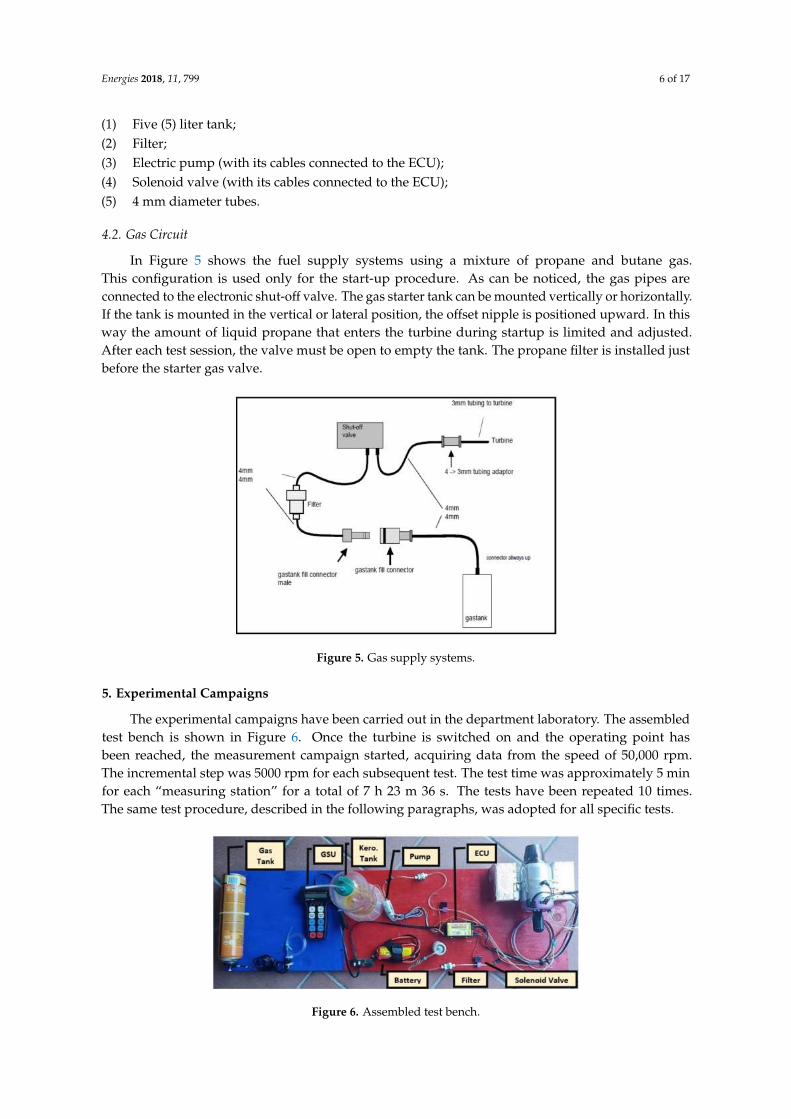