experimental demonstration of a resonator-induced...
TRANSCRIPT
Experimental Demonstration of a Resonator-Induced Phase Gatein a Multiqubit Circuit-QED System
Hanhee Paik,1,* A. Mezzacapo,1 Martin Sandberg,1 D. T. McClure,1 B. Abdo,1 A. D. Córcoles,1 O. Dial,1
D. F. Bogorin,2 B. L. T. Plourde,2 M. Steffen,1 A.W. Cross,1 J. M. Gambetta,1 and Jerry M. Chow1
1IBM T. J. Watson Research Center, Yorktown Heights, New York 10598-0218, USA2Department of Physics, Syracuse University, Syracuse, New York 13244-1130, USA
(Received 6 June 2016; published 13 December 2016)
The resonator-induced phase (RIP) gate is an all-microwave multiqubit entangling gate that allows ahigh degree of flexibility in qubit frequencies, making it attractive for quantum operations in large-scalearchitectures. We experimentally realize the RIP gate with four superconducting qubits in a three-dimensional circuit-QED architecture, demonstrating high-fidelity controlled-Z (CZ) gates between allpossible pairs of qubits from two different 4-qubit devices in pair subspaces. These qubits are arrangedwithin a wide range of frequency detunings, up to as large as 1.8 GHz. We further show a dynamicalmultiqubit refocusing scheme in order to isolate out 2-qubit interactions, and combine them to generatea 4-qubit Greenberger-Horne-Zeilinger state.
DOI: 10.1103/PhysRevLett.117.250502
As recent progress in superconducting quantum pro-cessors has marched towards more complex networksof qubits [1–3], it becomes increasingly crucial to developrobust protocols for multiqubit control. In particular,there has been a considerable amount of work onimproving single- [4] and 2-qubit [5–7] controls for super-conducting qubits. Although the fidelity of single-qubitgates (>0.999) has already been pushed above fault-tolerant thresholds for error correction codes such as thesurface code [8,9], the study of 2-qubit gates in multiqubitsystems is still an area of great exploration.Currently, many 2-qubit gates for superconducting qubits
require specific arrangements of qubit frequencies to performoptimally. For example, the dynamically tuned controlled-Z(CZ) gate [5,10,11] functions through frequency tuning twoqubits into a specific resonance condition involving higherenergy levels, which will not work if any other existingenergy levels intervene between the qubits. A similarlimitation arises with the all-microwave cross-resonance(CR) gate [6,12–14]. The CR gate works for qubits withina narrow window of detunings defined by the anharmonicityof the qubit [15]. This restriction becomes accentuated inlarger networks of qubits where all qubit frequencies mustbe arranged within a small frequency window [16].A notable advantage of the resonator-induced phase (RIP)
gate [17,18] is its capability to couple qubits even if they arefar detuned from each other. Therefore, the RIP gate canovercome difficulties due to constraints on the frequencyarrangements that can hinder scalability towards largerquantum architectures. TheRIP gate is a CZ gate that exploitsstrong coupling between qubits and a resonator in a circuitquantum electrodynamics (cQED) system. It is realized byapplying a detuned microwave pulse to a shared bus cavity,without a strong requirement on the qubit frequencies. In
addition, it is insensitive to phase fluctuations of the drive,depending only on drive amplitude and detuning.In this Letter, we experimentally demonstrate the RIP gate
in two cQED devices, each composed of four three-dimensional transmon superconducting qubits [19] coupledto both a central bus cavity and individual readout cavities.First, we show that a variety of state-dependent phases areinduced by the RIP gate. Phases from weight two and threePauli operators are singled out using echo sequences. Ourexperiments confirm the predicted dependence of theacquired phases on drive amplitude and detuning. Then,
1 2
34
ggggωegggω…
Δ…
(a) (b)
(c) (d)
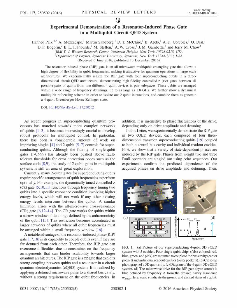
FIG. 1. (a) Picture of our superconducting 4-qubit 3D cQEDsystem with 5 cavities. Four single-qubit chips (false colored: red,blue, green, andpink) aremounted to couple to thebuscavity (centerpocket) and individual readout cavities (outer pockets). (b) Close-upphotograph of a 3Dqubit chip. (c)Diagram of the 4-qubit 3D cQEDsystem. (d) The microwave drive for the RIP gate (cyan arrow) isblue detuned by frequency Δ from the dressed cavity resonanceωgggg. Here, g and e indicate the ground and excited states of a qubit.
PRL 117, 250502 (2016) P HY S I CA L R EV I EW LE T T ER Sweek ending
16 DECEMBER 2016
0031-9007=16=117(25)=250502(5) 250502-1 © 2016 American Physical Society

we demonstrate the frequency flexibility by performing theRIP gate between 12 individual qubit pairs from two devices,with qubit-qubit detunings up to 1.8 GHz. High-fidelity CZ
gates are observed in pair subspaces using 2-qubit random-ized benchmarking (RB). Finally, using pairwise CZ inter-actions in the 4-qubit subspace, we generate a 4-qubitGreenberger-Horne-Zeilinger (GHZ) state.
Figure 1(a) shows our 4-qubit 3D cQED device. Thequbits are fabricated on heat exchanger method (HEM)sapphire substrates [20], diced into individual 2 × 6 mm2
chips [Fig. 1(b)], mounted in a 5-cavity enclosure machinedfrom 6061 aluminum. Our device is optimized for the bestperformance of RIP gates between all qubit pairs. Theoptimization is done by selecting individual qubit chips for
TABLE I. Parameters of the two 4-qubit devices, device A and device B. ωq is the qubit frequency, δ is the qubit anharmonicity, χ isthe qubit-bus dispersive frequency shift, ωc is the readout cavity frequency, T1 is the energy decay time of the qubit, T�
2 is the Ramseycoherence time, and Techo is the Hahn echo time. Values of T1, Techo, and T�
2 were measured multiple times throughout the experimentsand are listed as a range in the table. The bus cavity frequencies are 6.9676 GHz (device A) and 6.9710 GHz (device B). In both cases,the bus cavity has a decay rate κ=2π ¼ 7.7 kHz.
Qubit ωq=2π δ=2π χ=2π ωc=2π T1 Techo T�2 Qubit ωq=2π δ=2π χ=2π ωc=2π T1 Techo T�
2
index (GHz) (MHz) (MHz) (GHz) (μs) (μs) (μs) index (GHz) (MHz) (MHz) (GHz) (μs) (μs) (μs)
A1 5.7862 305 10 10.2020 26–36 36–40 6–17 B1 5.7828 303 6.8 10.1949 31–36 30–40 27A2 5.1459 304 3.7 10.0846 63–68 49–68 21–23 B2 4.5597 287 0.7 10.0805 88–90 46–86 48A3 6.3037 243 4.6 9.9799 45–59 22–34 12–42 B3 6.3657 234 6.7 9.9775 46–59 16–27 12A4 4.7630 280 2.2 9.8328 56–68 45–46 37 B4 4.9624 284 0.1 9.8553 38–45 33–36 18
0 500 1000 15000
10
10
1
ExperimentTheory
-130
-120
-110
-100
-90
-80
-70
-60
0 500 1000
-130
-120
-110
-100
-90
-80
-70
-60
Δ/2π
(MH
z)
(a)
Δ/2π = −98.6 MHz
Δ/2π = −118.6 MHz
Δ/2π = −137.6 MHz
1
01
01
0
(d)(c)
Δ/2π
(MH
z)
0 500 1000 0 500 1000
(b)
1
0.5
0
τ (ns)
0 500 1000
1
0.5
00 500 1000
P
P (e)
P
(f)
0 100
-120
-100
-80
-60
Δ/2π
(MH
z)
t (ns)
ExperimentTheory
∼ τ (ns)∼
τ (ns)∼ τ (ns)∼
τ (ns)∼
FIG. 2. (a) Excited state population (P↑) of the qubit A2 (see Table I) versus single RIP pulse gate time ~τ and detuning Δ=2π, fromRamsey experiments for Z2Z3 shown in (f). The red dashed line indicates a threshold time below which no coherent oscillation isobserved. (b) Theoretical prediction of ZZ oscillations at ~ϵR=2π ¼ 315 MHz. Inset: Simulated residual photons hnð~τÞi vs ~τ and Δ=2π.The red region indicates hnð~τÞi > 0.01; hnð~τÞi drops sharply after the threshold time. (c) P↑ of A1 for Z1Z2Z3 in (f), showing ZZZinteractions among qubits A1, A2, and A3 as a function of ~τ. (d) Theoretical calculation of ZZZ oscillations at ~ϵR=2π ¼ 200 MHz.(e) P↑ of A2 vs ~τ at three detuning points. ZZ oscillations from the experiment (blue circles) and theory (red curves) show goodagreement. The theoretical drive amplitude is fine-tuned at ~ϵR=2π ¼ 315� 15 MHz. (f) Illustration of the pulse sequences for theRamsey experiment (top) and 4-qubit refocused RIP gate schemes for Z2Z3 (middle) or Z1Z2Z3 (bottom).
PRL 117, 250502 (2016) P HY S I CA L R EV I EW LE T T ER Sweek ending
16 DECEMBER 2016
250502-2

frequency and coherence times. The parameters of the two4-qubit devices (device A and device B) are listed inTable I. Experimental setups are described in Ref. [21]. Thequbit states are measured via low-power dispersive readout[24]. The single-qubit and simultaneous RB results showthat all single-qubit gate fidelities are higher than 0.999[21], confirming no significant addressability errors [25].The RIP gate is operated by applying a microwave drive
detuned by Δ to the bus [see Fig. 1(d)]. During thisoperation, the bus cavity evolves adiabatically from itsinitial vacuum state, back to the vacuum at the end of thegate, and each state of the qubits acquires a state-dependentphase, due to a dispersive shift that leads to a differentdetuning from the drive frequency. These phases enable thegate to act as controlled-Z (CZ) gate, making the gateinsensitive to phase fluctuations in the drive [21].The action of the RIP gate is described by a sum of
Duffing oscillator Hamiltonians coupled to the bus cavity[21]. A large frequency difference between the qubits andthe bus cavity results in qubit-qubit photon exchanges.When the qubit frequencies are sufficiently spaced, thequbit-qubit exchanges become state-dependent shifts,with a static contribution and a dynamical one activatedby the cavity drive. In general, the gate activates many-body Pauli interactions of different weight, i.e., operatorswith different numbers of Pauli terms. In our system,Pauli interactions of weight two, exp½i_θZiZj
ZiZjt�, three,exp½i_θZiZjZk
ZiZjZkt�, and four, exp½i_θZ1Z2Z3Z4Z1Z2Z3Z4t�,
occur. The interaction rates depend on the state-dependentdispersive shifts, the drive amplitude ~ϵ, and Δ. With anunmodulated drive, the steady-state rates scale as _θZiZj
∝n̄χ=Δ, _θZiZjZk
¼ _θZiZjχ=Δ, and _θZ1Z2Z3Z4
¼ _θZiZjðχ=ΔÞ2,
where n̄ ¼ ðj~ϵj=2ΔÞ2 is the average number of photonsin the bus and χ is the state-dependent dispersive shift tothe bus. Since typically χ is much smaller than Δ, theinteraction rate slows down by χ=Δ as the weight of theinteraction increases.To observe the amplitude- and frequency-scaling behavior
of the phases from weight two and three Z operators, weperform a series of Ramsey experiments while applying theRIP gate. Refocused RIP gate schemes are designed for 4qubits to single out ZZ or ZZZ terms. The pulse sequencesare shown in Fig. 2(f). In the refocused RIP gate scheme, Xπ
pulses on each qubit are applied between RIP gate pulses,and echo away unwanted Z interactions of various Pauliweights. The sign of the phase of the interaction term Z2Z3
remains the same along the whole echo sequence, whereasall other Zi, ZiZj, ZiZjZk and Z1Z2Z3Z4 terms alternatesign along the sequence, resulting in no net phase accumu-lation. The RIP gate pulse is shaped in the form ~ϵRðtÞ ¼~ϵAf1þ cos½π cosðπt=~τÞ�g [26], where ~τ is the pulse width.This pulse shape suppresses the photon population of thecavity to third order in Δ, having zero time derivative up tothe third order, at the beginning and the end of the pulse [17].
Two-qubit interactions (Z2Z3) between qubits A2 andA3, and three-qubit interactions (Z1Z2Z3) between qubitsA1, A2, and A3 from device A are shown in Figs. 2(a)and 2(c), respectively, as a function of a single RIP gatepulse width ~τ and Δ. Both Z2Z3 and Z1Z2Z3 become fasterasΔ approaches zero, as predicted by the steady-state rates.The experimental Z2Z3 and Z1Z2Z3 are compared with aclosed-form solution for the density matrix of the system[21]. We find excellent agreement between the experiment[Figs. 2(a) and 2(c)] and theory [Figs. 2(b) and 2(d)],observing deviations of ∼0.5% in the pulse amplitude forthe different drive detunings. Figure 2(e) shows Z2Z3 fromthree different drive detunings. The deviations are likelyrelated to cavity nonlinearity and frequency-dependentattenuation of the drive lines.In our experiment, the rise time of the RIP gate pulse
shortens as the pulse width decreases in ~ϵRðtÞ. As a result,both the experiment and theory in Fig. 2 reveal a thresholdtime, below which the gate is strongly inhibited due tononadiabatic driving. A fast rise of the RIP gate pulse issignaled by the presence of residual photons in the bus at theend of the gate. The nonadiabatic time threshold is markedwith a red dashed line in Figs. 2(a) and 2(c) and is inverselyproportional to Δ. The closed-form solutions [21] indicate afinite amount of residual photons hnð~τÞi > 0.01 for short gatetimes, as plotted as the red region in the inset of Fig. 2(b).
0.990
0.985
0.980
0.975
0.970
0.9656055504540353025201510
0 10 20 30 40 500.50.60.70.80.9
1
0 10 20 30 40 500.50.60.70.80.9
1
P0
P0
Number of Cliffords
(b)
Fg
Δ/2π (MHz)
(c)Upper coherence limit
(a)
A2
A30 1500 3000
π
π
Lower coherence limit
P
t (ns)
Coherence + measurement-induced dephasing
FIG. 3. (a) Pulse sequence of the 2-qubit refocused RIP gatescheme and P↑ of a target qubit from a tune-up procedure using aRamsey experiment when a control qubit is in the ground state(blue) and in the excited state (red). (b) Population of j0i versusthe number of Cliffords from the 2-qubit RB on A2-A3 atΔ=2π ¼ 20 MHz with 40 randomization sequences (coloreddots). (c) ZZπ=2 fidelity between A2-A3 vs Δ=2π (red dots).The error bars are from the 2-qubit RB fit. Theoretical upper andlower limits on the gate fidelity without (black dashed line) andwith the measurement-induced dephasing (green region, dashedcurves) are calculated from minimum and maximum coherencetimes in Table I.
PRL 117, 250502 (2016) P HY S I CA L R EV I EW LE T T ER Sweek ending
16 DECEMBER 2016
250502-3

To demonstrate the flexibility of the RIP gatewith respectto qubit frequencies, we characterize the gate performancevia 2-qubit RB [7,27] over a large range of qubit-qubitdetuning Δq. For the characterization, we restrict ourexperiment to a 2-qubit subspace with the other two qubitsin the ground state. The 2-qubit refocused RIP gate scheme[28] [Fig. 3(a)] is used to realize a 2-qubit CZ generatorZZπ=2 ¼ exp½−iðπ=4ÞZZ�. The gate is tuned up usingRamsey experiments, shown in Fig. 2(f), by performingfirst a Xπ=2 gate on the target qubit, then applying therefocused RIP gate with a varying gate time. The final Yπ=2
on the target qubit ensures, when the phase of the targetqubit is �π=2, a maximal contrast between two Ramseycurves for each control qubit state. The lower plot in Fig. 3(a)shows two out-of-phase Ramsey curves as a function of gatetime from a tune-up procedure. In the tune-up, the minimumgate time is typically bounded by the nonadiabatic timethreshold, which is highlighted in pink in Fig. 3(a).An example of 2-qubit RB results is shown in Fig. 3(b).
We fit the 2-qubit RB result from each qubit to the decaymodel from Ref. [7,27] to obtain the base (α) of theexponential decay model, from which we extract the fidelityper two-qubit Clifford (FC), assuming perfect single-qubitgates. The fidelity per CZ gate (Fg) is then computed usingthe average number of CZ generators per Clifford (NC) withthe formula Fg ¼ 1 − ðd − 1Þð1 − α1=NCÞ=d, where d ¼ 4
is the dimension of the 2-qubit computational space andNC ¼ 1.5. A pair of fidelity data is obtained from two decaycurves in one RB run. The data shown in Fig. 3(b) andTable II are an average of the pair.High-fidelity ZZπ=2 interactions are achieved by the
RIP gate between all qubit pairs, up to 1.8 GHz in Δq
(see Table II). The fidelity data are summarized in Table II.The fidelity per Clifford ranges from 0.93 to 0.97, corre-sponding to 0.96–0.98 fidelity per CZ generator (seeTable II caption). The measurement-induced dephasingis a source of error, caused by the photons from the RIPgate that are entangled with qubits and leak out with qubitinformation [18]. However, we find that the effect ofmeasurement-induced dephasing [29] is small in ourdevices. The measurement-induced dephasing is investi-gated by measuring the gate fidelity while varying thedetuning of the RIP gate drive between A2 and A3, asshown in Fig. 3(c). The measurement-induced dephasing isexpected to worsen as the detuning decreases. The RIP gate
-0.5
0
0.5
-0.5
0
0.5
-0.5
0
0.5
0000
1110
1111
1111
0000
1110
0000
1110
1111
1111
0000
1110
-0.5
0
0.5
-0.5
0
0.5
-0.5
0
0.5
0000
1110
1111
1111
0000
1110
0000
1110
1111
1111
0000
1110
0000
1110
1111
1111
0000
1110
0000
1110
1111
1111
0000
1110
(a) (b) (c)
FIG. 4. (a) Experimentally reconstructed density matrix of a 4-qubit GHZ state from the quantum state tomography [30] performed ondevice A. The 4-qubit refocused RIP gate scheme is used to create the GHZ state. (b) Theoretically reconstructed ideal density matrix ofa 4-qubit GHZ state using the exact gate sequences from the experiment in (a). (c) Theoretical density matrix with static ZZ interactions.
TABLE II. RIP gate fidelities measured on 12 different qubitpairs in devices A and B with Δ=2π ¼ 40 MHz. Δq is thedetuning between control and target qubits, Tgate is the totalrefocused gate time shown in Fig. 3, ζ is the rate of static ZZinteraction, Fcoh is the coherence limit on the gate fidelity withthe worst T1 and Techo, FC is the fidelity per Clifford from the2-qubit RB, and Fg is the fidelity per CZ generator from theaverage number (NC) of generators per Clifford.
Δq=2π Qubit Tgate ζ=2π Fcoh FC Fg(GHz) pair (ns) (kHz)
0.383 A2-A4 525 60 0.9893 0.9577(6) 0.9787(3)0.403 B2-B4 760 10 0.9832 0.9320(12) 0.9655(6)0.518 A1-A3 285 138 0.9913 0.9665(9) 0.9831(4)0.583 B1-B3 472 156 0.9772 0.9554(6) 0.9775(3)0.637 A1-A2 285 107 0.9883 0.9683(9) 0.9841(4)0.820 B4-B1 472 34 0.9827 0.9501(7) 0.9748(4)1.023 A4-A1 461 60 0.9857 0.9532(8) 0.9764(4)1.158 A2-A3 413 60 0.9861 0.9709(7) 0.9853(3)1.223 B1-B2 424 16 0.9872 0.9651(7) 0.9825(3)1.403 B3-B4 424 10 0.9805 0.9486(4) 0.9741(2)1.541 A3-A4 509 30 0.9824 0.9674(6) 0.9836(3)1.806 B2-B3 424 23 0.9831 0.9670(6) 0.9834(3)
PRL 117, 250502 (2016) P HY S I CA L R EV I EW LE T T ER Sweek ending
16 DECEMBER 2016
250502-4

pulse width is fixed at 266.7 ns (total refocused RIP gatetime is 570 ns), and we keep the gate time constant byadjusting the drive amplitude for all drive detuning. At the20 MHz detuning, the fidelity per Clifford is 0.9709(7),corresponding to 0.9853(3) for the fidelity per CZ generator,which is close to the lower fidelity bound imposed by thecoherence times and the measurement-induced dephasing.We find no appreciable dependence on the detuning ofthe RIP drive down to 12 MHz, and below 12 MHz thegate does not work due to nonadiabaticity. The overallRIP gate fidelity (∼0.97) is close to the coherence limit(0.980–0.985), and the estimated error from the measure-ment-induced dephasing is about 10−3 at the lowestdetuning of 12 MHz.Finally, we implement 4-qubit refocused RIP gate
schemes [Fig. 2(f)] to perform pairwise CZ gates in the4-qubit space [21]. Using the 4-qubit refocused schemes,we generate a maximally entangled 4-qubit GHZ state[jΨi ¼ 1=
ffiffiffi
2p ðj0000i − ij1111iÞ] in device A using CZ
gates between the qubit pairs A1-A2, A2-A3, and A3-A4.Single RIP pulse widths are 203 ns for A1-A2 and A2-A3,and 173 ns for A3-A4, which makes the total CZ gate timesto be 1.871 μs for A1-A2 and A2-A3 and 1.631 μs forA3-A4 with the single-qubit pulse width of 36.7 ns. Theresulting GHZ density matrix is shown in Fig. 4(a). Thestate fidelity to the ideal GHZ state [Fig. 4(b)] is 60.5%with a maximum likelihood estimation, which is partlylimited by decoherence during the long gate, and imperfecttuning of the 4-qubit refocused RIP gate scheme. We findthat static ZZ interactions can model some of the non-ideality observed in the experiment, reproducing erroneouscomponents in the density matrix [Fig. 4(c)].In summary, we have implemented the RIP gate in
4-qubit superconducting 3D cQED systems. The RIP gateinduces ZZ interactions, which are insensitive to phasefluctuations in the drive, easing requirements on phasestability for the qubit microwave controls. We have charac-terized 12 2-qubit CZ gates amongst a wide range of qubitfrequency detunings, spanning up to 1.8 GHz, and demon-strated high fidelity. This flexibility in qubit frequencies andthe demonstrated high fidelitymake theRIP gate an attractivetool for quantum operations in a large-scale architecture.
We thank Easwar Magesan, Jim Rozen, and SarahSheldon for experimental discussions and Markus Brink,George Keefe, and Mary Beth Rothwell for device fab-rication. We acknowledge support from IARPA underContract No. W911NF-10-1-0324.H. P., A. M., and M. S. contributed equally to this work.
*[email protected][1] J. Kelly et al., Nature (London) 519, 66 (2015).[2] D. Risté, S. Poletto, M.-Z. Huang, A. Bruno, V. Vesterinen,
O.-P. Saira, and L. DiCarlo, Nat. Commun. 6, 6983 (2015).
[3] A. D. Córcoles, E. Magesan, S. J. Srinivasan, A. W. Cross,M. Steffen, J. M. Gambetta, and J. M. Chow, Nat. Commun.6, 6979 (2015).
[4] S. Sheldon, L. S. Bishop, E. Magesan, S. Filipp, J. M. Chow,and J. M. Gambetta, Phys. Rev. A 93, 012301 (2016).
[5] R. Barends et al., Nature (London) 508, 500 (2014).[6] S. Sheldon, E. Magesan, J. M. Chow, and J. M. Gambetta,
Phys. Rev. A 93, 060302 (2016).[7] A. D. Córcoles, J. M. Gambetta, J. M. Chow, J. A. Smolin,
M. Ware, J. Strand, B. L. T. Plourde, and M. Steffen, Phys.Rev. A 87, 030301 (2013).
[8] S. B. Bravyi and A. Yu. Kitaev, arXiv:quant-ph/9811052.[9] A. G. Fowler, M. Mariantoni, J. M. Martinis, and A. N.
Cleland, Phys. Rev. A 86, 032324 (2012).[10] F. W. Strauch, P. R. Johnson, A. J. Dragt, C. J. Lobb, J. R.
Anderson, and F. C. Wellstood, Phys. Rev. Lett. 91, 167005(2003).
[11] L. DiCarlo et al., Nature (London) 460, 240 (2009).[12] G. S. Paraoanu, Phys. Rev. B 74, 140504(R) (2006).[13] C. Rigetti and M. Devoret, Phys. Rev. B 81, 134507
(2010).[14] J. M. Chow et al., Phys. Rev. Lett. 107, 080502 (2011).[15] E. Magesan (unpublished).[16] M. Takita, A. D. Córcoles, E. Magesan, B. Abdo, M. Brink,
A. Cross, J. M. Chow, and J. M. Gambetta, Phys. Rev. Lett.117, 210505 (2016).
[17] A.W. Cross and J. M. Gambetta, Phys. Rev. A 91, 032325(2015).
[18] S. Puri and A. Blais, Phys. Rev. Lett. 116, 180501(2016).
[19] H. Paik et al., Phys. Rev. Lett. 107, 240501 (2011).[20] O. Dial, D. T. McClure, S. Poletto, G. A. Keefe, M. B.
Rothwell, J. M. Gambetta, D. W. Abraham, J. M. Chow,and M. Steffen, Supercond. Sci. Technol. 29, 044001(2016).
[21] See Supplemental Material at http://link.aps.org/supplemental/10.1103/PhysRevLett.117.250502, which in-cludes Refs. [22, 23], for additional details on the exper-imental setup and a theoretical model of the system.
[22] F. Motzoi, J. M. Gambetta, P. Rebentrost, and F. K. Wilhelm,Phys. Rev. Lett. 103, 110501 (2009).
[23] J. Koch, T. M. Yu, J. Gambetta, A. A. Houck, D. I. Schuster,J. Majer, A. Blais, M. H. Devoret, S. M. Girvin, and R. J.Schoelkopf, Phys. Rev. A 76, 042319 (2007).
[24] B. Abdo, F. Schackert, M. Hatridge, C. Rigetti, and M.Devoret, Appl. Phys. Lett. 99, 162506 (2011).
[25] J. M. Gambetta et al., Phys. Rev. Lett. 109, 240504(2012).
[26] S. M. Girvin (unpublished).[27] E. Magesan, J. M. Gambetta, and J. Emerson, Phys. Rev.
Lett. 106, 180504 (2011).[28] J. M. Chow, J. M. Gambetta, A. W. Cross, S. T. Merkel,
C. Rigetti, and M. Steffen, New J. Phys. 15, 115012(2013).
[29] J. Gambetta, A. Blais, D. I. Schuster, A. Wallraff, L.Frunzio, J. Majer, M. H. Devoret, S. M. Girvin, and R. J.Schoelkopf, Phys. Rev. A 74, 042318 (2006).
[30] C. A. Ryan, B. R. Johnson, J. M. Gambetta, J. M. Chow, M.P. da Silva, O. E. Dial, and T. A. Ohki, Phys. Rev. A 91,022118 (2015).
PRL 117, 250502 (2016) P HY S I CA L R EV I EW LE T T ER Sweek ending
16 DECEMBER 2016
250502-5