experimental demonstrations of semi...
TRANSCRIPT
Experimental Demonstrations ofSemi-Autonomous Control
Mark Campbell, Raffaello D’Andrea, Jin-woo Lee, Eelco Scholte
Department of Mechanical and Aerospace EngineeringCornell University, Ithaca NY, 14853
{mc288,rd28,jl206,es244}@cornell.edu
Abstract— This paper describes two experimental testbedswhich focus on real time verification and validation of semi-autonomous cooperative control. RoboFlag is an experimentaland real time simulation of a capture the flag game usingrobots. The SeaScan is a long endurance UAV designed formilitary and commercial applications. For each testbed, detailsof hardware, simulators, current results, and experiment plansare given.
I. INTRODUCTION
Research supporting applications where operators controlmultiple vehicles has been on the rise in recent years. Awide variety of applications are fueling the work, suchas battlefield management, search and rescue, and spaceexploration. The challenges with these problems include:1) developing “cooperation” amongst the vehicles, 2) de-veloping higher level strategies and resource management,3) interfacing the vehicles with the operator in a predictablemanner, 4) Understanding and modeling the interface be-tween the operator and vehicles, and 4) verifying the resultsusing high fidelity simulations and experiments.
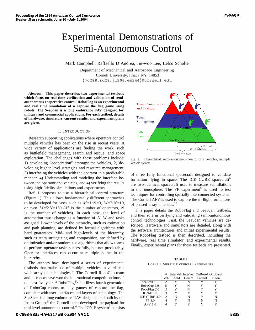
Ref. 1 proposes to use a hierarchical control structure(Figure 1). This allows fundamentally different approachesto be developed for cases such as M=1:N=3, M=2:N=10,or even M=5:N=150 (M is the number of operators, Nis the number of vehicles). In each case, the level ofautomation must change as a function of N, M and tasksassigned. Lower levels of the hierarchy, such as estimationand path planning, are defined by formal algorithms withhard guarantees. Mid- and high-levels of the hierarchy,such as team strategizing and composition, are defined byoptimization and/or randomized algorithms that allow teamsto perform operator tasks successfully, but not predictably.Operator interfaces can occur at multiple points in thehierarchy.
The authors have developed a series of experimentaltestbeds that make use of multiple vehicles to validate awide array of technologies I. The Cornell RoboCup teamand its robots have won the international competition four ofthe past five years.2 RoboFlag3], [4 utilizes fourth generationof RoboCup robots to play games of capture the flag,complete with user interfaces and layers of technology. TheSeaScan is a long endurance UAV designed and built by theInsitu Group;5 the Cornell team developed the payload formid-level autonomous control.6 The ION-F system7 consists
Fig. 1. Hierarchical, semi-autonomous control of a complex, multiplevehicle system.
of three fully functional spacecraft designed to validateformation flying in space. The ICE CUBE spacecraft8
are two identical spacecraft used to measure scintillationsin the ionosphere. The FF experiment9 is used to testtechniques for controlling spatially interconnected systems.The Cornell AFV is used to explore the in-flight formationsof phased array antennas.10
This paper details the RoboFlag and SeaScan testbeds,and their role in verifying and validating semi-autonomouscontrol technologies. First, the SeaScan vehicles are de-scribed. Hardware and simulators are detailed, along withthe software architectures and initial experimental results.The RoboFlag testbed is then described, including thehardware, real time simulator, and experimental results.Finally, experimental plans for these testbeds are presented.
TABLE I
CORNELL MULTIPLE VEHICLE EXPERIMENTS.
# InterVeh InterVeh OnBoard OnBoardVeh Coord Comm Control Auton
SeaScan 1.2 2 Y N Y YRoboCup 6.0 6 Y N Y YRoboFlag 2.0 11 Y N Y Y
ION-F 1.0 3 Y Y Y YICE CUBE 3.0 2 N N Y N
FF 3.0 4 Y N N NAFV 1.0 4 Y Y Y Y
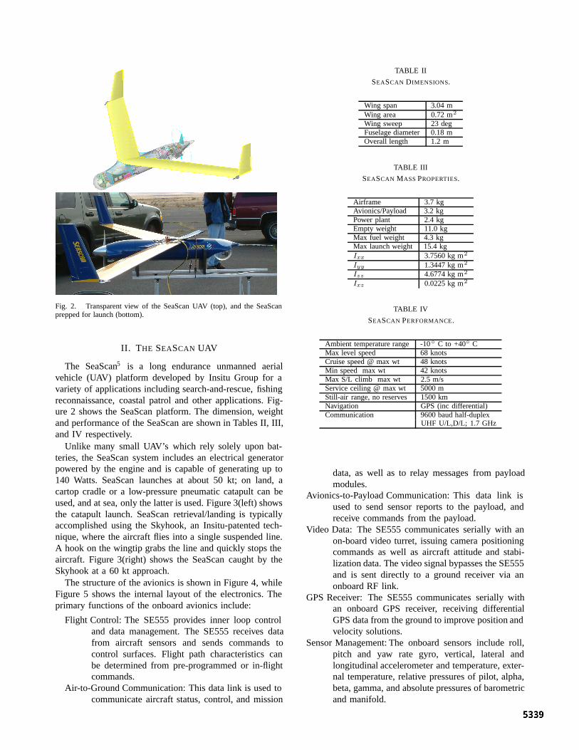
Fig. 2. Transparent view of the SeaScan UAV (top), and the SeaScanprepped for launch (bottom).
II. THE SEASCAN UAV
The SeaScan5 is a long endurance unmanned aerialvehicle (UAV) platform developed by Insitu Group for avariety of applications including search-and-rescue, fishingreconnaissance, coastal patrol and other applications. Fig-ure 2 shows the SeaScan platform. The dimension, weightand performance of the SeaScan are shown in Tables II, III,and IV respectively.
Unlike many small UAV’s which rely solely upon bat-teries, the SeaScan system includes an electrical generatorpowered by the engine and is capable of generating up to140 Watts. SeaScan launches at about 50 kt; on land, acartop cradle or a low-pressure pneumatic catapult can beused, and at sea, only the latter is used. Figure 3(left) showsthe catapult launch. SeaScan retrieval/landing is typicallyaccomplished using the Skyhook, an Insitu-patented tech-nique, where the aircraft flies into a single suspended line.A hook on the wingtip grabs the line and quickly stops theaircraft. Figure 3(right) shows the SeaScan caught by theSkyhook at a 60 kt approach.
The structure of the avionics is shown in Figure 4, whileFigure 5 shows the internal layout of the electronics. Theprimary functions of the onboard avionics include:
Flight Control: The SE555 provides inner loop controland data management. The SE555 receives datafrom aircraft sensors and sends commands tocontrol surfaces. Flight path characteristics canbe determined from pre-programmed or in-flightcommands.
Air-to-Ground Communication: This data link is used tocommunicate aircraft status, control, and mission
TABLE II
SEASCAN DIMENSIONS.
Wing span 3.04 mWing area 0.72 m2
Wing sweep 23 degFuselage diameter 0.18 mOverall length 1.2 m
TABLE III
SEASCAN MASS PROPERTIES.
Airframe 3.7 kgAvionics/Payload 3.2 kgPower plant 2.4 kgEmpty weight 11.0 kgMax fuel weight 4.3 kgMax launch weight 15.4 kgIxx 3.7560 kg m2
Iyy 1.3447 kg m2
Izz 4.6774 kg m2
Ixz 0.0225 kg m2
TABLE IV
SEASCAN PERFORMANCE.
Ambient temperature range -10◦ C to +40◦ CMax level speed 68 knotsCruise speed @ max wt 48 knotsMin speed max wt 42 knotsMax S/L climb max wt 2.5 m/sService ceiling @ max wt 5000 mStill-air range, no reserves 1500 kmNavigation GPS (inc differential)Communication 9600 baud half-duplex
UHF U/L,D/L; 1.7 GHz
data, as well as to relay messages from payloadmodules.
Avionics-to-Payload Communication: This data link isused to send sensor reports to the payload, andreceive commands from the payload.
Video Data: The SE555 communicates serially with anon-board video turret, issuing camera positioningcommands as well as aircraft attitude and stabi-lization data. The video signal bypasses the SE555and is sent directly to a ground receiver via anonboard RF link.
GPS Receiver: The SE555 communicates serially withan onboard GPS receiver, receiving differentialGPS data from the ground to improve position andvelocity solutions.
Sensor Management: The onboard sensors include roll,pitch and yaw rate gyro, vertical, lateral andlongitudinal accelerometer and temperature, exter-nal temperature, relative pressures of pilot, alpha,beta, gamma, and absolute pressures of barometricand manifold.

Fig. 3. SeaScan UAV ready for catapult launch (left). SeaScan “landing”using the skyhook system.
The Cornell developed payload module is designedto implement mid- and high-level control commands.State/parameter estimation, fault detection, and path plan-ning are realized within this module. The payload is anEmbedded Planet 8260 board with a Motorola PPC8260processor. The processor performs at 570MIPS, 300Mhz,and includes 64MB RAM, 32MB Flash, two serial ports,and is VxWorks 5.4 compatible. The power specificationsare 1.5Amps, 5V max.
A. Simulators
Two simulators exist for developing and testing algo-rithms before flight. The first is a software only simulatorin C++. Validation at this level tests interfaces to the flightcode, as well as the relative speed of the implementation.It does not, however, verify the real time implementationof the coding. The hardware in the loop simulation in-cludes not only the full avionics suite, but also a set ofservo mechanisms that mimic the on-board actuators, RFcommunication for air-to-ground, and a high fidelity aircraftdynamics simulator.
B. Sample Experimental Results
The focus of the research implemented on the SeaScanvehicles includes on-line model development using nonlin-ear estimation techniques, estimating and tracking systemfaults, reconfiguration of the control after a fault, pathplanning, and coordination of multiple SeaScans. In Nov2003 and Jan 2004, the Insitu/Cornell team demonstratedthe first systems level validation of the SeaScan/Cornellpayload system. The launch of the SeaScan is shown inFigure 6.
The Cornell payload was fed raw sensor data at 10Hzfrom the primary CPU, and a nonlinear sigma point filterwas used to estimate the aerodynamic model on-line.11 Apath planner on the payload board was also implemented.The planner selected “orbits” (R, X, Y, Z) and bow tiepatterns based on on-board, and delivered commands to theSeaScan CPU. Figure 7 shows the 3D position estimatesof the filter over time. The planner based orbits, orbits atdifferent altitudes, and bow tie patterns can each be seen.
Fig. 4. SeaScan Avionics structure.
Fig. 5. Nose off view of the SeaScan: Parallel boards plug into a “shaped”backplane in the form of the fuselage (top to bottom): Cornell payload,CPU+GPS+modem, Power.
C. Experiment Plans
In the near term, two sets of flight experiments areplanned, demonstrating:
Model Estimation: Single vehicle aerodynamics will beestimated during normal operations and duringan aileron fault. Nonlinear estimators (SPF’s,11
ESMF’s,12 and hybrid estimator13) will be imple-mented. Integration with on-line model predictivecontrol14 will be tested.
Path Planning for Target Pursuit: A streamline basedpath planner, as well as an evolutionary pathplanner will be implemented. Basic path planningaround obstacles, with risk, and in target pursuit
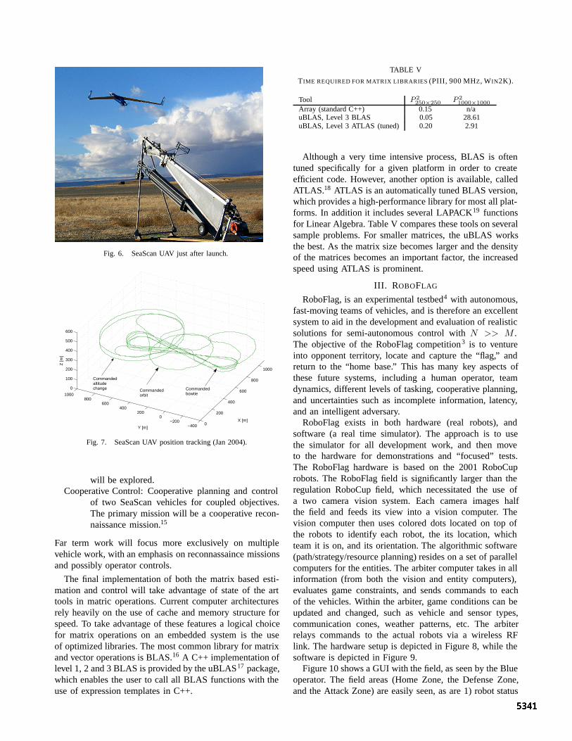
Fig. 6. SeaScan UAV just after launch.
0
200
400
600
800
1000
−400−200
0200
400600
8001000
0
100
200
300
400
500
600
X [m]
Y [m]
Z [m
]
Commanded altitude change Commanded
orbit
Commanded bowtie
Fig. 7. SeaScan UAV position tracking (Jan 2004).
will be explored.Cooperative Control: Cooperative planning and control
of two SeaScan vehicles for coupled objectives.The primary mission will be a cooperative recon-naissance mission.15
Far term work will focus more exclusively on multiplevehicle work, with an emphasis on reconnassaince missionsand possibly operator controls.
The final implementation of both the matrix based esti-mation and control will take advantage of state of the arttools in matric operations. Current computer architecturesrely heavily on the use of cache and memory structure forspeed. To take advantage of these features a logical choicefor matrix operations on an embedded system is the useof optimized libraries. The most common library for matrixand vector operations is BLAS.16 A C++ implementation oflevel 1, 2 and 3 BLAS is provided by the uBLAS17 package,which enables the user to call all BLAS functions with theuse of expression templates in C++.
TABLE V
TIME REQUIRED FOR MATRIX LIBRARIES (PIII, 900 MHZ, WIN2K).
Tool P 2250×250 P 2
1000×1000Array (standard C++) 0.15 n/auBLAS, Level 3 BLAS 0.05 28.61uBLAS, Level 3 ATLAS (tuned) 0.20 2.91
Although a very time intensive process, BLAS is oftentuned specifically for a given platform in order to createefficient code. However, another option is available, calledATLAS.18 ATLAS is an automatically tuned BLAS version,which provides a high-performance library for most all plat-forms. In addition it includes several LAPACK19 functionsfor Linear Algebra. Table V compares these tools on severalsample problems. For smaller matrices, the uBLAS worksthe best. As the matrix size becomes larger and the densityof the matrices becomes an important factor, the increasedspeed using ATLAS is prominent.
III. ROBOFLAG
RoboFlag, is an experimental testbed4 with autonomous,fast-moving teams of vehicles, and is therefore an excellentsystem to aid in the development and evaluation of realisticsolutions for semi-autonomous control with N >> M .The objective of the RoboFlag competition3 is to ventureinto opponent territory, locate and capture the “flag,” andreturn to the “home base.” This has many key aspects ofthese future systems, including a human operator, teamdynamics, different levels of tasking, cooperative planning,and uncertainties such as incomplete information, latency,and an intelligent adversary.
RoboFlag exists in both hardware (real robots), andsoftware (a real time simulator). The approach is to usethe simulator for all development work, and then moveto the hardware for demonstrations and “focused” tests.The RoboFlag hardware is based on the 2001 RoboCuprobots. The RoboFlag field is significantly larger than theregulation RoboCup field, which necessitated the use ofa two camera vision system. Each camera images halfthe field and feeds its view into a vision computer. Thevision computer then uses colored dots located on top ofthe robots to identify each robot, the its location, whichteam it is on, and its orientation. The algorithmic software(path/strategy/resource planning) resides on a set of parallelcomputers for the entities. The arbiter computer takes in allinformation (from both the vision and entity computers),evaluates game constraints, and sends commands to eachof the vehicles. Within the arbiter, game conditions can beupdated and changed, such as vehicle and sensor types,communication cones, weather patterns, etc. The arbiterrelays commands to the actual robots via a wireless RFlink. The hardware setup is depicted in Figure 8, while thesoftware is depicted in Figure 9.
Figure 10 shows a GUI with the field, as seen by the Blueoperator. The field areas (Home Zone, the Defense Zone,and the Attack Zone) are easily seen, as are 1) robot status
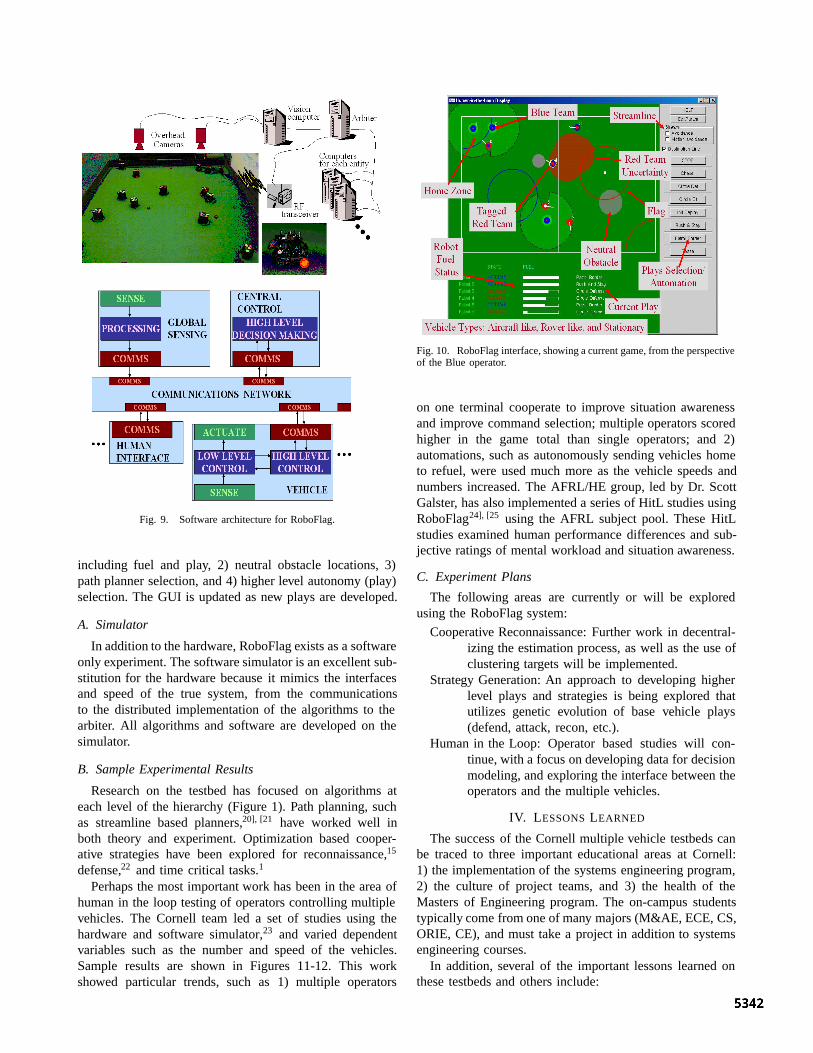
Fig. 8. RoboFlag hardware.
Fig. 9. Software architecture for RoboFlag.
including fuel and play, 2) neutral obstacle locations, 3)path planner selection, and 4) higher level autonomy (play)selection. The GUI is updated as new plays are developed.
A. Simulator
In addition to the hardware, RoboFlag exists as a softwareonly experiment. The software simulator is an excellent sub-stitution for the hardware because it mimics the interfacesand speed of the true system, from the communicationsto the distributed implementation of the algorithms to thearbiter. All algorithms and software are developed on thesimulator.
B. Sample Experimental Results
Research on the testbed has focused on algorithms ateach level of the hierarchy (Figure 1). Path planning, suchas streamline based planners,20], [21 have worked well inboth theory and experiment. Optimization based cooper-ative strategies have been explored for reconnaissance,15
defense,22 and time critical tasks.1
Perhaps the most important work has been in the area ofhuman in the loop testing of operators controlling multiplevehicles. The Cornell team led a set of studies using thehardware and software simulator,23 and varied dependentvariables such as the number and speed of the vehicles.Sample results are shown in Figures 11-12. This workshowed particular trends, such as 1) multiple operators
Fig. 10. RoboFlag interface, showing a current game, from the perspectiveof the Blue operator.
on one terminal cooperate to improve situation awarenessand improve command selection; multiple operators scoredhigher in the game total than single operators; and 2)automations, such as autonomously sending vehicles hometo refuel, were used much more as the vehicle speeds andnumbers increased. The AFRL/HE group, led by Dr. ScottGalster, has also implemented a series of HitL studies usingRoboFlag24], [25 using the AFRL subject pool. These HitLstudies examined human performance differences and sub-jective ratings of mental workload and situation awareness.
C. Experiment Plans
The following areas are currently or will be exploredusing the RoboFlag system:
Cooperative Reconnaissance: Further work in decentral-izing the estimation process, as well as the use ofclustering targets will be implemented.
Strategy Generation: An approach to developing higherlevel plays and strategies is being explored thatutilizes genetic evolution of base vehicle plays(defend, attack, recon, etc.).
Human in the Loop: Operator based studies will con-tinue, with a focus on developing data for decisionmodeling, and exploring the interface between theoperators and the multiple vehicles.
IV. LESSONS LEARNED
The success of the Cornell multiple vehicle testbeds canbe traced to three important educational areas at Cornell:1) the implementation of the systems engineering program,2) the culture of project teams, and 3) the health of theMasters of Engineering program. The on-campus studentstypically come from one of many majors (M&AE, ECE, CS,ORIE, CE), and must take a project in addition to systemsengineering courses.
In addition, several of the important lessons learned onthese testbeds and others include:
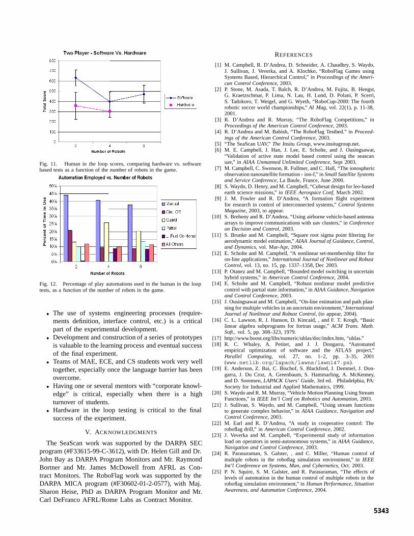
Fig. 11. Human in the loop scores, comparing hardware vs. softwarebased tests as a function of the number of robots in the game.
Fig. 12. Percentage of play automations used in the human in the looptests, as a function of the number of robots in the game.
• The use of systems engineering processes (require-ments definition, interface control, etc.) is a criticalpart of the experimental development.
• Development and construction of a series of prototypesis valuable to the learning process and eventual successof the final experiment.
• Teams of MAE, ECE, and CS students work very welltogether, especially once the language barrier has beenovercome.
• Having one or several mentors with “corporate knowl-edge” is critical, especially when there is a highturnover of students.
• Hardware in the loop testing is critical to the finalsuccess of the experiment.
V. ACKNOWLEDGMENTS
The SeaScan work was supported by the DARPA SECprogram (#F33615-99-C-3612), with Dr. Helen Gill and Dr.John Bay as DARPA Program Monitors and Mr. RaymondBortner and Mr. James McDowell from AFRL as Con-tract Monitors. The RoboFlag work was supported by theDARPA MICA program (#F30602-01-2-0577), with Maj.Sharon Heise, PhD as DARPA Program Monitor and Mr.Carl DeFranco AFRL/Rome Labs as Contract Monitor.
REFERENCES
[1] M. Campbell, R. D’Andrea, D. Schneider, A. Chaudhry, S. Waydo,J. Sullivan, J. Veverka, and A. Klochko, “RoboFlag Games usingSystems Based, Hierarchical Control,” in Proceedings of the Ameri-can Control Conference, 2003.
[2] P. Stone, M. Asada, T. Balch, R. D’Andrea, M. Fujita, B. Hengst,G. Kraetzschmar, P. Lima, N. Lau, H. Lund, D. Polani, P. Scerri,S. Tadokoro, T. Weigel, and G. Wyeth, “RoboCup-2000: The fourthrobotic soccer world championships,” AI Mag, vol. 22(1), p. 11-38,2001.
[3] R. D’Andrea and R. Murray, “The RoboFlag Competitions,” inProceedings of the American Control Conference, 2003.
[4] R. D’Andrea and M. Babish, “The RoboFlag Testbed.” in Proceed-ings of the American Control Conference, 2003.
[5] “The SeaScan UAV,” The Insitu Group, www.insitugroup.net.[6] M. E. Campbell, J. Han, J. Lee, E. Scholte, and J. Ousingsawat,
“Validation of active state model based control using the seascanuav,” in AIAA Unmanned Unlimited Conference, Sept 2003.
[7] M. Campbell, C. Swenson, R. Fullmer, and C. Hall, “The ionosphericobservation nanosatellite formation - ion-f,” in Small Satellite Systemsand Service Conference, La Baule, France, June 2000.
[8] S. Waydo, D. Henry, and M. Campbell, “Cubesat design for leo-basedearth science missions,” in IEEE Aerospace Conf, March 2002.
[9] J. M. Fowler and R. D’Andrea, “A formation flight experimentfor research in control of interconnected systems,” Control SystemsMagazine, 2003, to appear.
[10] S. Breheny and R. D’Andrea, “Using airborne vehicle-based antennaarrays to improve communications with uav clusters,” in Conferenceon Decision and Control, 2003.
[11] S. Brunke and M. Campbell, “Square root sigma point filtering foraerodynamic model estimation,” AIAA Journal of Guidance, Control,and Dynamics, vol. Mar-Apr, 2004.
[12] E. Scholte and M. Campbell, “A nonlinear set-membership filter foron-line applications,” International Journal of Nonlinear and RobustControl, vol. 13, no. 15, pp. 1337–1358, Dec 2003.
[13] P. Otanez and M. Campbell, “Bounded model switching in uncertainhybrid systems,” in American Control Conference, 2004.
[14] E. Scholte and M. Campbell, “Robust nonlinear model predictivecontrol with partial state information,” in AIAA Guidance, Navigationand Control Conference, 2003.
[15] J. Ousingsawat and M. Campbell, “On-line estimation and path plan-ning for multiple vehicles in an uncertain environment,” InternationalJournal of Nonlinear and Robust Control, (to appear, 2004).
[16] C. L. Lawson, R. J. Hanson, D. Kincaid, , and F. T. Krogh, “Basiclinear algebra subprograms for fortran usage,” ACM Trans. Math.Soft., vol. 5, pp. 308–323, 1979.
[17] http://www.boost.org/libs/numeric/ublas/doc/index.htm, “ublas.”[18] R. C. Whaley, A. Petitet, and J. J. Dongarra, “Automated
empirical optimization of software and the ATLAS project,”Parallel Computing, vol. 27, no. 1–2, pp. 3–35, 2001(www.netlib.org/lapack/lawns/lawn147.ps).
[19] E. Anderson, Z. Bai, C. Bischof, S. Blackford, J. Demmel, J. Don-garra, J. Du Croz, A. Greenbaum, S. Hammarling, A. McKenney,and D. Sorensen, LAPACK Users’ Guide, 3rd ed. Philadelphia, PA:Society for Industrial and Applied Mathematics, 1999.
[20] S. Waydo and R. M. Murray, “Vehicle Motion Planning Using StreamFunctions,” in IEEE Int’l Conf on Robotics and Automation, 2003.
[21] J. Sullivan, S. Waydo, and M. Campbell, “Using stream functionsto generate complex behavior,” in AIAA Guidance, Navigation andControl Conference, 2003.
[22] M. Earl and R. D’Andrea, “A study in cooperative control: Theroboflag drill,” in American Control Conference, 2002.
[23] J. Veverka and M. Campbell, “Experimental study of informationload on operators in semi-autonomous systems,” in AIAA Guidance,Navigation and Control Conference, 2003.
[24] R. Parasuraman, S. Galster, , and C. Miller, “Human control ofmultiple robots in the roboflag simulation environment,” in IEEEInt’l Conference on Systems, Man, and Cybernetics, Oct. 2003.
[25] P. N. Squire, S. M. Galster, and R. Parasuraman, “The effects oflevels of automation in the human control of multiple robots in theroboflag simulation environment,” in Human Performance, SituationAwareness, and Automation Conference, 2004.