experimental flight of kit student’s rocket in france€¦ · in addition to the technical...
TRANSCRIPT

1. INTRODUCTION
Under the control of CNES (Centre National D’Etudes Spatiales), the French non-profit organization Planète Sciences has been conducting for amateur clubs, such as university students and young engineers, an experimental rocket launch campaign called “La Campagne Nationale de Lancement” .[1]
The purpose of the rocket launch campaign is not only to make their dream come true but also to teach them how the actual development is processed.
In addition to the technical process toward rocket launch, the amateur clubs learn a lot of team work and project management concerning schedule and budged. These kinds of practical activity are important and necessary aspects for actual development [2].
2. ROCKET PROFILE
A student group of Kyushu Institute of Technology has been participated in the French experimental rocket launch campaign since 2006 [3-5]. This paper focuses on the technical aspect to introduce the newest design and development of the rocket launched in 2008.
After the ignition, the rocket reaches to an altitude of 500m in 11 seconds. During the coasting flight, the roll is controlled by ailerons to maintain the doors of ejection system bay upward. At the apogee, the door of ejection system bay is opened, and a drogue chute is ejected to deploy parafoil. When the rocket begins to perform steady gliding flight and the onboard microcomputer establishes signal processing from GPS (Global Positioning System) satellites, the navigation calculation starts to guide the rocket to an aiming point. Fig.1 shows the mission sequence.
Fig. 1 Mission sequence
2.1 Outline of rocket
The KIT student’s experimental rocket for the rocket launch campaign in 2008 consists of four major structural components called nose cone, avionics bay, ejection system bay and engine bay as shown in Fig. 2. The rocket has the total length of about 2.3m including the pitot tube, and weighs about 15kg. The major dimensions of rocket and aerodynamic parameters are summarized in Table 1.
Fig. 2 KIT student’s experimental rocket
Table 1 Major dimensions and aerodynamic parameters
Specifications Requirement [6]Total length L [mm] 2,314 ≤ 4000 Body diameter φ [mm] 182 40 ≤≤φ 200
Mass M [kg] 14.8 ≤ 15 Lift derivative nC [-] 19.2 15 ≤≤ nC 40
Moment derivative
mC = × SM nC [-] 54.5 40 ≤≤ mC 100
Drug coefficient DC [-] 0.34 NA
Static margin SM: in terms of body diameter (before combustion)
[-] 2.8
2 ≤≤ SM 6
Launcher exit speed [m/s] 21 ≤ 20
Experimental Flight of KIT Student’s Rocket in France
Koji Okuda*, Yuji Ujimoto*, Yuta Otsuka*, Takaya Sato*, Takuya Shidooka*, Daijiro Semba*, Kenichi Tominaga*, Junichi Fukuda*, Yuta Yamamoto*, Kazuki Wada*, Shinichi Sagara*,
and Koichi Yonemoto* *Kyushu Institute of Technology, 1-1 Sensui, Tobata, Kitakyushu, Fukuoka, 804-8550, Japan
(Tel/Fax : +81-93-884-3179; E-mail: [email protected]) Abstract: KIT Student’s Rocket has been developed by a student group of Kyushu Institute of Technology for rocket launch campaign held at La Courtine in France since 2006. This paper introduces the newest design of rocket. The rocket has the body length of 2120mm, and weighs 14.6kg and can reach to an altitude of about 700m by a solid rocket motor provided by CNES (the French Centre National D’Etudes Spatiales). The rocket is controlling rolling attitude during ascent phase and then deploying a parafoil at the apogee of the trajectory for recovery guidance to an aiming point. Keywords: Rocket, Parafoil recovery system, Guidance and control, Roll control by aileron
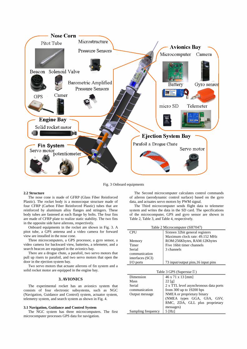
Fig. 3 Onboard equipments
The Second microcomputer calculates control commands
of aileron (aerodynamic control surface) based on the gyro data, and actuates servo motors by PWM signal.
2.2 Structure The nose cone is made of GFRP (Glass Fiber Reinforced
Plastic). The rocket body is a monocoque structure made of four CFRP (Carbon Fiber Reinforced Plastic) tubes that are reinforced by aluminum alloy flanges and stringers. These body tubes are fastened at each flange by bolts. The four fins are made of CFRP plate to realize static stability. The two fins in the opposite side have ailerons, respectively.
The Third microcomputer sends flight data to telemeter system and writes the data in the SD card. The specifications of the microcomputer, GPS and gyro sensor are shown in Table 2, Table 3, and Table 4, respectively.
Onboard equipments in the rocket are shown in Fig. 3. A pitot tube, a GPS antenna and a video camera for forward view are installed in the nose cone.
Table 2 Microcomputer (SH7047) CPU Sixteen 32bit general registers
Maximum clock rate: 49.152 MHz Memory ROM:256Kbytes, RAM:12Kbytes Timer Five 16bit timer channels Serial communication interfaces (SCI)
3 channels
I/O ports 73 input/output pins,16 input pins
Three microcomputers, a GPS processor, a gyro sensor, a video camera for backward view, batteries, a telemeter, and a search beacon are equipped in the avionics bay.
There are a drogue chute, a parafoil, two servo motors that pull up risers to parafoil, and two servo motors that open the door in the ejection system bay.
Two servo motors that actuate ailerons of fin system and a solid rocket motor are equipped in the engine bay.
Table 3 GPS (SuperstarⅡ)
Dimension 46 x 71 x 13 [mm] Mass 22 [g] Serial communication
2 x TTL level asynchronous data ports from 300 up to 19200 bps
Output message NMEA or proprietary binary (NMEA types GGA, GSA, GSV, RMC, ZDA, GLL plus proprietary messages)
Sampling frequency 5 [Hz]
3. AVIONICS
The experimental rocket has an avionics system that consists of four electronic subsystems, such as NGC (Navigation, Guidance and Control) system, actuator system, telemetry system, and search system as shown in Fig. 4. 3.1 Navigation, Guidance and Control System
The NGC system has three microcomputers. The first microcomputer processes GPS data for navigation.

Fig. 4 Onboard avionics
Table 5 Telemetry system Table 4 Gyro sensor (MTi)
Dynamic range all angles in 3D Angular resolution 0.05° RMS Static Accuracy (roll/pitch) <0.5° Static Accuracy (heading) <1.0° Dynamic Accuracy 2° RMS Update Rate Max 100 Hz
Transmission frequency 1, 2 137.95, 138.5 [MHz] Serial communication 4800 [bps] FSK modulator chip XR2206 FSK demodulators chip XR2211 Low state, high state 9 [KHz], 15 [KHz]
3.3 Power supply system The power supply system has four batteries of 7.2 Volts DC
as shown in Fig. 6. 3.2 Telemetry System
The block diagram telemetry system is shown in Fig. 5. The flight information is converted to voice signal and transmitted by the telemetry system called KIWI [7] to the ground support equipment of CNES. The specification of the telemetry system is shown in Table 5.
Fig. 6 Power supply system Fig. 5 Onboard and ground telemetry system

The first and the second batteries supply 5V DC through the regulator to the NGS system. The third battery supplies 12V DC through the DC-DC converter to the telemetry system and the search system respectively. The fourth and the fifth batteries supply 7.4V DC to the servo motor used for controlling parafoil risers and regulated 6V DC to the servo motors to open the ejection doors and to control ailerons of fin system.
4. Ejection system bay Fig. 9 Parafoil container
4.1 Parafoil recovery system
The parafoil recovery system is shown in Fig. 7. The servo motors draw the right and left control lines of the parafoil to deflect the right and left trailing edges respectively. The deflection of trailing edge causes drag increase to yield yawing moment for turn maneuver.
Fig. 10 Ejection system
Fig. 7 Parafoil risers and control lines The drogue chute ejection system is shown in Fig. 11. There is a sector board to lock the drogue chute ejection box. The servo motor rotates the sector board to release the drogue chute ejection box immediately after the ejection doors open.
4.2 Ejection system
The parafoil ejection sequence is shown in Fig. 8. A drogue chute is ejected immediately after the ejection door is opened. The drogue chute pulls out the parafoil to deploy.
Fig. 11 Drogue chute ejection system
5. Fin system
The fin system is illustrated in Fig.12 and Fig. 13.
Fig. 8 Ejection sequence
The ejection system bay is shown in Fig. 9 and Fig. 10. Two ejection doors are attached by spring hinges on each side of body. The parafoil is folded up and stored in the container made of cloth. Since the container cloth is stuck to inside of the bay by Velcro, it can be removed and attached easily.
Fig. 12 Servo motor linkage of aileron
5.2 Wind tunnel test The wind tunnel test was conducted to demonstrate the control law of fin system using a test setup as shown in Fig. 15. It took about 2 seconds for the rocket to achieve the target angle from a large disturbed roll angle for the free stream velocity of 20m/s.
Fig. 13 Fin system
The two ailerons are integrated to the two fins in the opposite side respectively. The each aileron is connected to the servo motor by a mechanical link shaft.
Fig. 15 Wind tunnel test of fin system The purpose of the fin system with aileron is to control rolling motion of rocket so as to eject the drogue chute upward. If the drogue chute is ejected downward, there is a risk that the parafoil drawn by the drogue chute collides with the body of rocket to result in deployment failure. Therefore the rolling attitude at the instance of drogue chute ejection is considered one of the important events to achieve successful parafoil gliding.
7. ROCKET LAUNCH CAMPAIGN
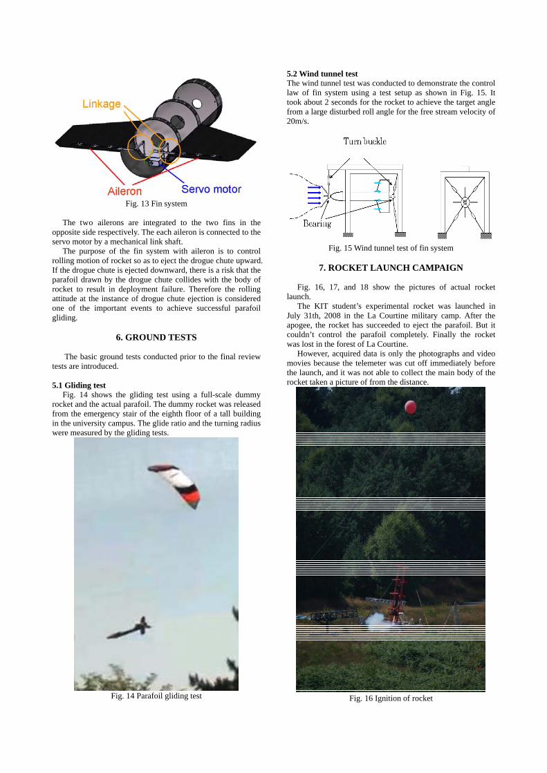
Fig. 16, 17, and 18 show the pictures of actual rocket
launch. The KIT student’s experimental rocket was launched in
July 31th, 2008 in the La Courtine military camp. After the apogee, the rocket has succeeded to eject the parafoil. But it couldn’t control the parafoil completely. Finally the rocket was lost in the forest of La Courtine.
6. GROUND TESTS
However, acquired data is only the photographs and video
movies because the telemeter was cut off immediately before the launch, and it was not able to collect the main body of the rocket taken a picture of from the distance.
The basic ground tests conducted prior to the final review tests are introduced. 5.1 Gliding test
Fig. 14 shows the gliding test using a full-scale dummy rocket and the actual parafoil. The dummy rocket was released from the emergency stair of the eighth floor of a tall building in the university campus. The glide ratio and the turning radius were measured by the gliding tests.
Fig. 14 Parafoil gliding test Fig. 16 Ignition of rocket

ACKNOWLEDGMENTS
The authors would like to thank all the volunteers of the Planete Sciences and the specialists of CNES for their kind supports and hospitalities when we faced critical problems in La Courtine. In addition to aforementioned personnel, the authors wish to extend the acknowledgment especially to Mr. Christophe Scicluna for his vital encouragement of our participation in this rocket launch campaign in France.
REFERENCES [1] http://www.planete-sciences.org/espace [2] C. Scicluna, K. Ogimoto, M. Sasaki, and K. Yonemoto,
“ The French National Rockets Launching Campaign and its Dawn of Collaboration with Japanese Amateur Space Clubs,” IAC-07-E1.1.04, The 58th International Astronautical Congress, Hyderabad, India, September 24-28, 2007.
[3] K. Yonemoto, S. Sagara, T. Yato, T. Nakamura, Y. Hiroki, S. Fujie, and M. Hoshino, “The Student Rocket of KIT Flies in the French Sky of La Courtine,” Proceedings of the 50th Space Science and Technology Conference, pp.667-672, November 8-10, 2006 (in Japanese).
[4] T. Yato, Y. Hiroki, I. Shida, S. Sagara, and K. Yonemoto, “Navigation, Guidance and Control of Parafoil Recovery System,” Proceedings of the 2006 KSAS-JSASS Joint International Symposium on Aerospace Engineering, pp.6-11, Busan, Korea, November 15-17, 2006.
[5] S. Kaji, Y. Oshikata, T. Akiyama, Y. Harada, D. Sugihara, T. Shimozawa, S. Sagara, and K. Yonemoto, “Design and Development of KIT Student’s Experimental Rocket” Proceedings of the 2007 KSAS-JSASS Joint International Symposium on Aerospace Engineering, pp.308-311, Kitakyushu, Japan, October 10-12, 2007.
Fig. 17 Powered flight of rocket
[6] “Book of Specifications Single Stage Experimental Rockets (Version 2.1),” Planéte Sciences/CNES (Centre National D’Etudes Spatiales), issued on 15th October, 2004.
[7] “KIWI-Millenium Telemetry System Comprehensive Data Sheet,” Planéte Sciences/CNES (Centre National D’Etudes Spatiales), issued in May, 2007.
Fig. 18 Gliding using parafoil