experimental investigation and ann modeling on improved performance of an innovative method of using...
TRANSCRIPT

RESEARCH ARTICLE
Srinivasan CHANDRASEKARAN, Arunachalam AMARKARTHIK, Karuppan SIVAKUMAR,Dhanasekaran SELVAMUTHUKUMARAN, Shaji SIDNEY
Experimental investigation and ANN modeling on improvedperformance of an innovative method of using heaveresponse of a non-floating object for ocean wave energyconversion
© Higher Education Press and Springer-Verlag Berlin Heidelberg 2013
Abstract To convert wave energy into usable forms ofenergy by utilizing heaving body, heaving bodies (buoys)which are buoyant in nature and float on the water surfaceare usually used. The wave exerts excess buoyancy forceon the buoy, lifting it during the approach of wave crestwhile the gravity pulls it down during the wave trough. Ahydraulic, direct or mechanical power takeoff is used toconvert this up and down motion of the buoy to produceusable forms of energy. Though using a floating buoy forharnessing wave energy is conventional, this device facesmany challenges in improving the overall conversionefficiency and survivability in extreme conditions. Up tothe present, no studies have been done to harness oceanwaves using a non-floating object and to find out the meritsand demerits of the system. In the present paper, aninnovative heaving body type of wave energy converterwith a non-floating object was proposed to harness waves.It was also shown that the conversion efficiency and safetyof the proposed device were significantly higher than anyother device proposed with floating buoy. To demonstratethe improvements, experiments were conducted with non-floating body for different dimensions and the heaveresponse was noted. Power generation was not consideredin the experiment to observe the worst case response of theheaving body. The device was modeled in artificial neural
network (ANN), the heave response for various parameterswere predicted, and compared with the experimentalresults. It was found that the ANN model could predictthe heave response with an accuracy of 99%.
Keywords ocean wave energy, point absorbers, heavingbody, non-floating object, heave response ratio, artificialneural network (ANN)
1 Introduction
Wave energy technologies are usually classified by themethod of capturing energy from waves, location at the seaand power take-off (PTO) system. The method of waveenergy capture is classified into point absorbers or buoy;attenuators, oriented parallel to wave propagation at itssurface; terminators, oriented normal to wave propagation;oscillating water column; and wave overtopping devices.Wave energy converters are categorized, based on theirlocation, into onshore device; near shore device; andoffshore device. Various PTO methods employed bydifferent wave energy devices are seen in literature, butfew are hydraulic ram, hydraulic turbine, pneumaticturbine, pump to shore, mechanical gearbox and lineargenerators [1,2].Presently, most wave energy devices use the rise and fall
motion of waves to produce other usable forms of energy,while a few use the sway motion of waves. Most existingdevices focus on the fact that employed technology shallbe simple in construction and working, maximum energytransmitted to internal components shall be limited evenduring rough weather, and devices shall be capable ofharnessing maximum possible energy even from low densewaves. It is also seen that the design invoking precisionand high technique manufacturing of internal components
Received January 23, 2013; accepted March 26, 2013
Srinivasan CHANDRASEKARANDepartment of Ocean Engineering, Indian Institute of TechnologyMadras, Chennai 600036, India
Arunachalam AMARKARTHIK (✉), Karuppan SIVAKUMAR,Dhanasekaran SELVAMUTHUKUMARAN, Shaji SIDNEYDepartment of Mechanical Engineering, Bannari Amman Institute ofTechnology, TamilNadu 638401, IndiaE-mail: [email protected]
Front. Energy 2013, 7(3): 279–287DOI 10.1007/s11708-013-0268-4

shall result in high initial investment. Further, the use ofhydraulic or pneumatic turbines requires uniform waveforces. Hence, a successful device shall be designed takinginto consideration all the factors mentioned above.
2 Point absorbers in heave
Of the existing devices reported, heaving point absorbersare the most common. The proposed device is developedon a similar principle. Critical review of the existingmechanisms is conducted to compare the advantage of thenewly proposed device. Most of the heaving pointabsorbers are designed for offshore applications, whichare either submerged in water or floating on the surface [1].As point absorbers are small in dimension in comparison tothe average wavelength, they are restricted to heave motiononly. A rotary, direct-drive wave energy device proposedball screw arrangement is used for converting the heavemotion of the float into rotation [2]. The float stores energyduring its upward stroke as potential energy and suppliesenergy to the internal system during down stroke. A fullscale prototype of linear generator, mounted on sea floor isconnected to a floating buoy for harnessing wave energy[3]. The spring stores energy during the upward stroke ofthe piston as the wave crest passes. An improved deviceemploying deep-draft spar and annular saucer shaped buoythat is restricted to heave motion with respect to the spar ismade use of and the spring is loaded to restore the forcesfor down stroke [4]. A mechanical type of float and counterweight system of wave energy uses a surface floating buoythat is kept hanging by a cable, and counter weight isattached to the other end of the cable which runs through apulley, enabling it to rotate when the float heaves. Thecables slag during the upward stroke of the buoy so that thegenerator is disconnected through a ratchet mechanism [5].Archimedes wave swing (AWS) [6] is a completelysubmerged linear generator type of wave energy converterbuilt at the Portuguese coast. The device comprises of afloor-mounted cylindrical chamber enclosed by a floaterthat moves relative to the cylinder when encountered bywaves. The air inside the cylinder acts as a spring andprovides restoring force to the floater. The linear generatorsinstalled inside the cylinder produce electrical energy fromthe heave movement of the floater. A recent technologydeveloped by Ocean Navitas Ltd [7], uses a unidirectionalgearbox that produces continuous unidirectional rotationfrom the up and down motion of the buoy. The buoy storesand harnesses energy during upward stroke as potentialenergy and releases it in downfall to the unidirectionalgearbox. A similar device is also employed on heavingbody wave energy conversion and its performance isanalyzed by adding a supplementary mass [8].From the brief review of literature, it is seen that the
employed devices have few common characteristics thatmake them less efficient in conversion and vulnerable to
extreme conditions. All the heaving body type of waveenergy converters use buoy or float to harness the up anddown motion of ocean waves to produce other usableforms of energy. These buoys are specifically designed tomove along the waves to provide maximum output. Manybuoys are further developed to provide more than oneheave amplitude ratios. The most efficient device has ademerit of having excessive heave displacement duringextreme conditions. Many solutions have been provided torestrict the device from breaking during extreme heavedisplacements. Researchers have proposed various damp-ing schemes such as mechanical stoppers, latching control,hydraulic damping through modifying float forms andmodifying the natural frequency by changing the systemmass to keep the buoy under control in extremecircumstances. The extremely rough and corrosive natureof the ocean environment makes any control strategyunreliable for a long working life.All reviewed point absorbers use floating buoy to
harness waves. The buoy is pushed up during the approachof crest by buoyancy force and pulled down by gravityduring the wave trough. This action makes the buoyharness waves in the up stroke and produce potentialenergy or spring energy; meanwhile the portion ofharnessed energy is transmitted to the power takeoffsystem. During the down stroke, the wave does not provideany energy to the buoy which releases the stored potentialenergy to the power takeoff system while coming downdue to gravity. This action makes any floating buoy type ofwave energy converters harness only one cycle of waves toproduce usable energy while leaving the other wave cyclefree.It is also another difficulty for a few point absorbers that
the buoys are connected through a rigid link at the wavesurface. The breaking waves during rough weather lead toa huge mechanical stress on the device and damage thesystem. All the difficulties mentioned above make heavingbuoy type of wave energy converters less efficient andvulnerable to extreme conditions.
3 Non-floating body in heave
In the present paper, an out of box device was proposedwhich used a non-floating object to harness waves [9] toproduce electrical energy. The device looked like aconventional floater type of point absorber, but it wascompletely unique in its working principle. The unique-ness in the operation of the device provided improvedperformance per unit wave front and enhanced safetyduring extreme conditions.The device was a near shore converter and had to be kept
on a rigid platform or jetty well above the maximum sealevel. The entire system would be kept on the platform anda non-floating object would be kept vertically hangingfrom the device through a metal rope. The said non-
280 Front. Energy 2013, 7(3): 279–287

floating object would be the only part of the device whichinteracted with the waves and harnessed its energy. Figure1 shows the solid model of the proposed device.
3.1 Oscillating arm assembly
This was a straight rigid frame pivoted at its center on abearing supported shaft. A vertically oriented non-floatingobject (in this case a cylindrical water filled steel containerwas used as non-floating object) was made hanging fromone end of the arm. A ballasting tank was mounted on theother end of the arm as counter mass. The mass of theballasting tank would be varied by filling or draining waterinto and from it. The length of the flexible cable or metalcable was made adjustable. Initially, the volume of thewater container would be twice that of the ballasting tank.
3.2 Unidirectional gearbox
Many different methods were patented to convert bothpositive and negative directional rotation into continuousunidirectional rotation. The proposed unidirectional gear-box was also one such unique patent pending technologywhich provided energy in the form of continuousunidirectional rotation from alternatively rotating inputshaft. The proposed unidirectional gearbox was simple inconstruction and converted alternative rotation at its inputshaft into continuous unidirectional rotation at its outputshaft with a conversion efficiency of approximately 95%.
3.3 Step up gearbox
Due to the fact that the frequency of ocean waves is verylow, the speed of rotation from the unidirectional gearboxis lower than what is required by any conventionalgenerator. Hence another gearbox was coupled with theunidirectional gearbox to increase the speed of rotation.
3.4 Electrical generator
A conventional rotary type of electrical generator wascoupled with the output shaft of the step up gearbox toconvert mechanical rotation into electrical energy.
4 Working of non-floating body heavingwave energy converter
4.1 Initial condition
The entire setup was mounted on a platform such that thehanging water container was completely immersed into thewater surface. When the ballasting tank was filled withwater, the container started rising above water as an actionof balancing. The cable length was adjusted such that thearm was horizontal after the exposed height of thecontainer reached the required height. Once all the initialarrangements were made, the arm was in equilibrium dueto the balancing of effective mass (m) of the semiimmersed container and counter mass (M).
4.2 Working
When an incidental wave passed the semi immersedcontainer, as illustrated in Fig. 2, the effective mass (m) ofthe container got reduced due to the increase in surround-ing water height, and the arm became unbalanced betweenits two ends. The counter mass (M) pulled the container upas an action of balancing. This action made the arm tooscillate in one direction. When the wave troughapproached the container, the effective weight of thecontainer increased due to the decrease in the water heightaround it, which, in turn, made the container side heavyand pulls the counter mass side up. This alternativebalancing of forces made the arm continuously oscillatewith respect to the point O.
This oscillation of arm made the input gear ofunidirectional gearbox rotate alternatively, and the uni-directional gearbox produced unidirectional rotation at itsoutput shaft. This low speed high torque unidirectional
Fig. 1 Solid model of proposed device
Fig. 2 Schematic of oscillating arm at incident wave
Srinivasan CHANDRASEKARAN et al. Ocean wave energy conversion 281

energy was converted into high speed rotation by a step upgearbox and further converted into electrical energythrough the rotary electrical generator.
4.3 Uniqueness
The oscillation of heaving body was caused by thevariation in the effective mass of the container duringwave action instead of by the pushing action of wave crest.Hence, the excessive heave response was not possibleduring extreme waves as the waves could not push the non-floating object up. The heave response of the arm waslimited by changing the quantity of water in the ballastingtank. The heaving mass was connected via cable to thedevice and hence extreme forces were not transferred to theinternal components of the device. As the wave does notpush the container, the rope was always in tension and theenergy could be harnessed in both wave cycles. Nomechanical energy storing system was used such asmechanical or pneumatic spring or dead weight to storethe energy for the down stroke and hence there was lessmechanical damping.
5 Experimental arrangement
An experimental setup shown in Fig. 1 was designed andfabricated to test in 1 m deep, 2 m wide wave flume atIndian Institute of Technology Madras. Preliminary studieswere conducted to find the heave response of water filledcontainer with respect to wide range of regular waves.Undamped free oscillation in regular wave represented theworst case scenario. Hence, the study was done withoutconnecting any electrical generator or exposing it toirregular waves to find the heave response in extremeconditions.The wave periods experimented was between 1 and 3 s
for the laboratory model, which could be scaled up to therequired wave field. The model was kept 5 m from thewave peddle at the 2 m wave flume at IIT madras. Thecontainer was installed 0.8 m from side walls.The device was a two degree of freedom system, the arm
had a freedom to oscillate in heave, and the container had afreedom to oscillate in the surge. The surge motion of thecontainer was not constrained to study the effect of it inover all conversion.
5.1 Water container
Four water containers, as shown in Fig. 3, made of steelwith a height of 0.7 m with different dimensions andshapes were used for the experiment. Three of them werecircular in the cross section with a diameter of 0.2, 0.3 and0.4 m. One of the floats was with a cross section of square,having a side of 300 mm. All the containers were bottom
opened and with an air vent at the top to drain the air outduring installation.
5.2 Oscillating arm
The oscillating arm was 2 m in length and was pivoted atits center by a bearing supported shaft. A 6 mm metal ropewas connected at one end of the said arm and a wormgearbox was fixed to vary the length of the rope. Therewere arrangements to hang the container at the outer end ofthe rope.
5.3 Unidirectional and step up gearboxes
An unidirectional gearbox and step up gearbox to step thespeed for 12 times were fabricated and coupled together.The entire assembly was mounted on the wave flume andthe container was kept hanging from the trailing end of thearm.
6 Experiment
An experimental setup depicted in Fig. 4 was used for theexperiment. A 0.3 m diameter and 0.7 m high cylindricalwater container was employed for the first phase. The tankwas inverted and immersed into the wave flume. The topair vent was kept open until the container got completelyimmersed into water. Once the container was completelyfilled with water, the air vent was closed and the countermass got loaded at the other end of the arm. A counter massof 25 kg was initially loaded and the arm was madehorizontal by adjusting the length of the rope.An accelerometer was mounted on one end of the
oscillating arm to measure the heave acceleration. A 10 kgflywheel was coupled at the output shaft of gearbox toprovide mechanical damping.The main focus of the experiment was to measure the
Fig. 3 Containers used for the experiment
282 Front. Energy 2013, 7(3): 279–287

heave response of the arm for various wave and deviceparameters. The power output and efficiency of the devicewas directly proportional to its heave response and hence itwas decided to analyze the heave response.
It was found from the experiment that the heaveresponse of the device exceeded the maximum waveamplitude in most of the cases, which suggested that theconversion rate of the proposed device was significantlyhigher. It was also found that the heave response wasdependent on variables such as counter mass, wave period,and wave height for a particular container diameter.The experiments were conducted by varying each
parameter and heave responses were noted. To study thedevice, the experiments were conducted for all possiblecombination of variables and heave responses werenoted.The counter mass was varied in three different levels
between 34 and 46 kg with 6 kg difference. The 10, 20, 25and 30 cm high waves were used for all counter masses andthe wave period was varied from 2 s to 3 s with a 0.2 svariation.To obtain the worst case response, regular waves were
used and heave response were noted. Table 1 presents theaverage maximum heave response (MHR) observed fromthe experiment for each combination and a comparison ofthe measured and predicted heave response by ANN.
Table 1 Comparison of measured and predicted heave response by ANN
Experimental observation Predicted
Serial No. Mass/kg Wave amplitude/cm Wave period/s MHR/cm Heave response ratio ANN model MHR/cm
1 34 10 2 18 1.8 18
2 34 10 2.2 21 2.1 21
3 34 10 2.4 16 1.6 15
4 34 10 2.6 12 1.2 13
5 34 10 2.8 12 1.2 13
6 34 10 3 20 2.0 20
7 34 20 2 36 1.8 36
8 34 20 2.2 44 2.2 44
9 34 20 2.4 33 1.7 33
10 34 20 2.6 24 1.2 24
11 34 20 2.8 24 1.2 24
12 34 20 3 15 0.8 14
13 34 25 2 41 1.6 40
14 34 25 2.2 48 1.9 48
15 34 25 2.4 41 1.6 41
16 34 25 2.6 32 1.3 32
17 34 25 2.8 30 1.2 30
18 34 25 3 21 0.8 21
19 34 30 2 38 1.3 39
20 34 30 2.2 52 1.7 51
21 34 30 2.4 48 1.6 48
22 34 30 2.6 35 1.2 35
23 34 30 2.8 58 1.9 58
24 34 30 3 50 1.7 50
25 40 10 2 14 1.4 12
Fig. 4 Experimental setup at 2 m wave maker
Srinivasan CHANDRASEKARAN et al. Ocean wave energy conversion 283

(Continued)Experimental observation Predicted
Serial No. Mass/kg Wave amplitude/cm Wave period/s MHR/cm Heave response ratio ANN model MHR/cm
26 40 10 2.2 21 2.1 21
27 40 10 2.4 17 1.7 17
28 40 10 2.6 15 1.5 15
29 40 10 2.8 22 2.2 22
30 40 10 3 15 1.5 15
31 40 20 2 27 1.4 27
32 40 20 2.2 43 2.2 43
33 40 20 2.4 42 2.1 42
34 40 20 2.6 33 1.7 33
35 40 20 2.8 42 2.1 42
36 40 20 3 37 1.9 37
37 40 25 2 32 1.3 32
38 40 25 2.2 49 2.0 49
39 40 25 2.4 52 2.1 52
40 40 25 2.6 35 1.4 35
41 40 25 2.8 48 1.9 48
42 40 25 3 39 1.6 39
43 40 30 2 38 1.3 38
44 40 30 2.2 52 1.7 52
45 40 30 2.4 62 2.1 61
46 40 30 2.6 48 1.6 48
47 40 30 2.8 48 1.6 48
48 40 30 3 43 1.4 43
49 46 10 2 15 1.5 14
50 46 10 2.2 24 2.4 24
51 46 10 2.4 19 1.9 19
52 46 10 2.6 14 1.4 15
53 46 10 2.8 26 2.6 26
54 46 10 3 20 2.0 20
55 46 20 2 23 1.2 23
56 46 20 2.2 40 2.0 40
57 46 20 2.4 44 2.2 44
58 46 20 2.6 37 1.9 37
59 46 20 2.8 48 2.4 48
60 46 20 3 40 2.0 40
61 46 25 2 30 1.2 30
62 46 25 2.2 48 1.9 48
63 46 25 2.4 58 2.3 58
64 46 25 2.6 41 1.6 41
65 46 25 2.8 55 2.2 55
66 46 25 3 48 1.9 48
67 46 30 2 32 1.1 32
68 46 30 2.2 49 1.6 50
69 46 30 2.4 65 2.2 63
284 Front. Energy 2013, 7(3): 279–287

7 Artificial neural network (ANN)
ANNs are modeling tools, which can be used to modelcomplex input and output relations. Presently, the ANN isused in a variety of fields to replace complex mathematicalequations. It is also successfully applied in various oceansciences and energy systems. For example, Kalogiroureviewed the application of ANN in energy systems [10],Deo and Sridhar Naidu used observed data to forecastwave parameters [11], Pao used ANN to forecast electricitymarket pricing [12], Tsai and Tsai converted pressuretransducer signals into various wave parameters usingtrained neural network [13], Carballo and Iglesias usedANN [14] to determine power performance of OscillatingWater Column at a particular coastal location.In the present study, the proposed novel device was
modeled on the ANN and its heave response waspredicted. The predicted values were experimentallyverified and it was found that the trained network predictedthe heave response with an accuracy of 99%.The principles and methodologies of training a ANN
was elaborated by Kalogirou [10], while Tsai and Tsai [13]presented the methodology of choosing weights, advan-tages of back-propagation neural networks (BPNN) inwave energy applications and selection of layers. Withreference to these studies, the proposed device wasmodeled on the ANN using Matlab.
7.1 Methodology
The wave height, wave period and counter mass were theinput parameters, which decided the heave response of thearm. These parameters were normalized between – 1 to 1and imported into Matlab.
7.2 Output parameter
The heave response in centimeter of arm was the onlyoutput parameter for the present study, as it was directlyproportional to the harnessed energy for a particularcounter mass.
7.3 Target data
Initially the ANN was supplied with corresponding heaveresponses obtained from experimental observation for the
given input parameters. The ANN used these parameters totrain itself by adjusting weights with each input parametersand combines to get the output.
7.4 Training network
BPNN was chosen as the network type [13] and gradientdecent method (GDM) was selected as the trainingfunction with 2 layers. 10 neurons were selected for initialtraining and could be increased if further accuracy wasneeded. Once the network was designed, the input and testdata were uploaded to the network whose learning rate andmomentum coefficient were varied by fixing epochs torequired runs. The network was trained by fixing the targetvalue as zero. The learning rate and momentum coefficientwere varied until the output was closer to zero. Once theleast value was obtained from the trained network, thenetwork was exported and saved.
7.5 Simulation
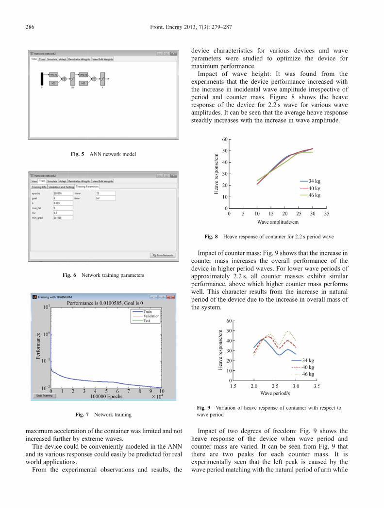
The trained network behaved as the device and predictedthe heave response once the required input parameterswere given. To validate the accuracy of the network,various input combinations were uploaded to the trainednetwork and the network was simulated. The networkprovided predicted heave response once the simulation wasdone. These values were de-normalized and comparedwith experimental observations. From the study, it wasfound that the predicted values were matching with anaccuracy of 99%. The predicted and experimented valueswere given in Table 1. Figure 5 displays the networkconfiguration with layers, Fig. 6 demonstrates the varioustraining parameters, and Fig. 7 exhibits the training ofnetwork.
8 Results and discussion
It was revealed from the experiment that the deviceexhibited significantly higher heave response than incidentwave amplitude between wave periods of 2 to 3 s. Theheave response of the proposed non-floating type of waveenergy converter was much higher than a conventionalbuoy type of wave energy converter. As the container wasonly pulled by the counter mass instead of by the wave, the
(Continued)Experimental observation Predicted
Serial No. Mass/kg Wave amplitude/cm Wave period/s MHR/cm Heave response ratio ANN model MHR/cm
70 46 30 2.6 53 1.8 54
71 46 30 2.8 68 2.3 66
72 46 30 3 52 1.7 52
Srinivasan CHANDRASEKARAN et al. Ocean wave energy conversion 285
maximum acceleration of the container was limited and notincreased further by extreme waves.The device could be conveniently modeled in the ANN
and its various responses could easily be predicted for realworld applications.From the experimental observations and results, the
device characteristics for various devices and waveparameters were studied to optimize the device formaximum performance.Impact of wave height: It was found from the
experiments that the device performance increased withthe increase in incidental wave amplitude irrespective ofperiod and counter mass. Figure 8 shows the heaveresponse of the device for 2.2 s wave for various waveamplitudes. It can be seen that the average heave responsesteadily increases with the increase in wave amplitude.
Impact of counter mass: Fig. 9 shows that the increase incounter mass increases the overall performance of thedevice in higher period waves. For lower wave periods ofapproximately 2.2 s, all counter masses exhibit similarperformance, above which higher counter mass performswell. This character results from the increase in naturalperiod of the device due to the increase in overall mass ofthe system.
Impact of two degrees of freedom: Fig. 9 shows theheave response of the device when wave period andcounter mass are varied. It can be seen from Fig. 9 thatthere are two peaks for each counter mass. It isexperimentally seen that the left peak is caused by thewave period matching with the natural period of arm while
Fig. 5 ANN network model
Fig. 6 Network training parameters
Fig. 7 Network training
Fig. 8 Heave response of container for 2.2 s period wave
Fig. 9 Variation of heave response of container with respect towave period
286 Front. Energy 2013, 7(3): 279–287

the second peak is derived from the matching of waveperiod with the natural period of container in surge. Theexperiment shows that the freedom to the container insurge gives advantage at higher counter masses and henceconstraining the container only in heave is not necessary.Net energy conversion is proportional to the system
mass and heave response of the device. The use of a non-floating object gives an advantage of having higher massper unit wave front than the floating buoy and hence theoverall energy conversion is increased. Due to the uniqueworking principle of the device, the heave response ofcontainer is four times the wave amplitude in wave periodswhich is closer to the natural period of oscillating arm.Both the above characteristics make the device have anexceptionally higher energy conversion rate. As the waveenergy is harnessed by the balance of masses instead of bythe pushing action of the wave, the energy transfer from thewave to the device is limited up to the capacity of thecounter mass and hence excessive energy cannot betransferred into the device in extreme conditions. Theheave response of the device is mainly based on thecontainer diameter and the counter mass. Changingdiameter of the float is not possible in the real sea scenariobut the ballasting tank can be drained completely and thecontainer can be immersed into water or be emptied tobring it above the water surface to prevent the device fromgetting damaged by extreme waves.
9 Conclusions
The investigation on using a non-buoyant object asreplacement to floating bodies in a point absorber hasbeen conducted and the performance characteristics werestudied. The present study has been performed bydisengaging the electrical PTO system and recording theheave response of the container. The net energy conversionis proportional to the heave response and the mass of thecontainer. Hence, the variation in heave response has beengiven importance in the present study to estimate theenergy conversion. The heave response ratio is the ratiobetween heave responses of the container and thecorresponding wave amplitude. Any device is consideredto be performing well when its heave response ratio ismore than unity. The experimental investigation shows thatthe heave response ratio of the device reaches up to 2.6when the wave frequency is closer to the natural frequencyof the device. Further study on the device characteristicshas indicated that the variation in the heave response of thedevice is proportional to the counter mass, wave amplitudeand wave period. From the analysis it has been found thatthe counter mass significantly affects the performance ofthe device. At higher frequency waves, improved perfor-mance is achieved by reducing the counter mass and viceversa for lower frequency waves. As the experimental
investigation has been performed and results have beenobtained, it becomes important to model the device using atool for making further analysis. Presently, ANN isextensively used by many researchers to model any systemto replace a conventional mathematical tool. In the presentstudy, it is proposed to find the possibility of using ANNfor ocean wave energy conversion application. The studyreveals that, using ANN for modeling a wave energyconverter is very much possible with greater accuracy.
References
1. De O, Falcão A F. Wave energy utilization: a review of the
technologies. Renewable & Sustainable Energy Reviews, 2009, 14
(3): 899–918
2. Falnes J. A review of wave-energy extraction. Marine Structures,
2007, 20(4): 185–201
3. Eriksson M, Waters R, Svensson O, Isberg J, Leijon M. Wave power
absorption: experiments in open sea and simulation. Journal of
Applied Physics, 2007, 102(8): 084910-1–084910-5
4. Elwood D, Yim S C, Prudell J, Stillinger C, von Jouanne A, Brekken
T, Brown A, Paasch R. Design, construction and ocean testing of a
taut-moored dual-body wave energy converter with a linear
generator power take-off. Renewable Energy, 2010, 35(2): 348–354
5. Agamloh E B, Wallace A K, von Jouanne A. A novel direct-drive
ocean wave energy extraction concept with contact-less force
transmission system. Renewable Energy, 2008, 33(3): 520–529
6. Polinder H, Damen M E C, Gardner F. Linear PM generator system
for wave energy conversion in the AWS. IEEE Transactions on
Energy Conversion, 2004, 19(3): 583–589
7. Al-Habaibeh A, Su D, McCague J, Knight A. An innovative
approach for energy generation from waves. Energy Conversion and
Management, 2010, 51(8): 1664–1668
8. Vantorre M, Banasiak R, Verhoeven R. Modelling of hydraulic
performance and wave energy extraction by a point absorber in
heave. Applied Ocean Research, 2004, 26(1–2): 61–72
9. Amarkarthik A, Chandrasekaran S, Sivakumar K, Sinhmar H.
Laboratory experiment on using non-floating body to generate
electrical energy from water waves. Frontiers in Energy, 2012, 6(4):
361–365
10. Kalogirou S A. Applications of artificial neural networks in energy
systems: a review. Energy Conversion and Management, 1999, 40
(10): 1073–1087
11. Deo M C, Sridhar Naidu C. Real time wave forecasting using neural
networks. Ocean Engineering, 1998, 26(3): 191–203
12. Pao H T. Forecasting electricity market pricing using artificial neural
networks. Energy Conversion and Management, 2007, 48(3): 907–
912
13. Tsai J C, Tsai C H. Wave measurements by pressure transducers
using artificial neural networks. Ocean Engineering, 2009, 36(15–
16): 1149–1157
14. Carballo R, Iglesias G. A methodology to determine the power
performance of wave energy converters at a particular coastal
location. Energy Conversion and Management, 2012, 61: 8–18
Srinivasan CHANDRASEKARAN et al. Ocean wave energy conversion 287