experimental investigation of a body flare for obtaining pitch
TRANSCRIPT

. X 62 62964 Copy I) q r'
••• •• RM A54J13 ~~----------------------------------------------~~~~ ,...., f-;, ~
I' ~ ~ ~ U ~ Z
DECLASSIFIED- ,.\ ~ - I ')... ~ (. AUTHORITY. MEMO, DROBKA 0 LEBOW DATED . ~/i?/&'''''
eclassitied by authority of NASA Classification 9hange Notices No. _7_~ - -Dated ** --1/-tCEf.k.v
RESEARCH MEMORANDUM
EXPERIMENTAL INVESTIGATION OF A BODY FLARE FOR OBTAINING
PITCH STABILITY AND A BODY FLAP FOR OBTAINING
PITCH CONTROL IN HYPERSONIC FLIGHT
By A. J . Eggers, Jr . , and Cla r ence A. Syvertson
Ames Aeronautical Labor ator y Moffett Field , Calif.
p'l
NATIONAL ADVISORY· COMMITTEE FOR AERONAUTICS
WA SH INGTON Januar y 18, 1955
https://ntrs.nasa.gov/search.jsp?R=19930088439 2018-04-02T18:46:41+00:00Z

•• . .. • • ••
••• • .. • •••
• · • •
••• .. • •
• •• · •
•
• ••
•• • • • •
• • • · . • •• • •
• · • •••
• • . • ••
• •• • .. • • ••
• • • • · • • • •

w NACA RM A54J13
•• • •• • • • •• .. . .. • ••• • • . · • • • . • • • • • · • • • •• • : CO~~D • • • • •• • •• • • •• . .. • • • • • • • ••• • • •• •• • • • ••• ••
NATIONAL ADVISORY COMMITTEE FOR AERONAUTICS
RESEARCH MEMORANDUM
EXPERIMENTAL INVESTIGATI ON OF A BODY FLARE FOR OBTAINING
PITCH STABI LITY AND A BODY FLAP FOR OBTAINING
PITCH CONTROL IN HYPERSONIC FLIGHT
By A. J. Eggers, Jr ., a nd Clarence A. Syvertson
SUMMARY
The effectiveness of a body flare as a pi tch- stabilizing device and a body f l ap as a p i t ch- control device has been i nvestigated experimentall y at Mach numbers from 3 . 00 to 6 .25 . The basic test body was rotat i onally symmetric and cons i sted of a fineness ratio 3 nose followed by a fineness ratio 9 afterbody . The body flare was conical and Was added at the base . The body f l ap consisted of a defl ectable section of the sur face of the cylindrical afterbody . This sect i on Was 1 . 59 body di ameters l ong , 780 of arc in ci rcumferential extent , and was centered 8.5 body diameters aft of the nose . Tests were conducted at angles of attack from -250 to +250 and flap deflection angles of 00 , - 10°, and - 25°.
Experimentally determined i ncrements in lift and drag due to flap deflection are compared at a Mach number of 5 wi th the predictions of the generalized shock- expansion theory and Newtonian impact theory . Both theories are in reasonab l y good agreement with experiment at small angles of attack . The trim lift coeffic i ents and l ift - drag ratios of the test configurat i on are found to increase steadil y wi th incr easing Mach number, becomi ng greater than those of a comparable all -movabl e- wing control at the higher Mach numbers of the tests . The body flar e and flap have, then , the attractive possibility at high supersonic a irspeeds of providing stability and control in pitch, whi l e at the same time they should be less vulnerable than planar airfoil s to aerodynamic heating .
I NTRODUCTION
The design of aircraft suitab l e for f light at high supersonic airspeeds is in substantial part dictated by considerations of aerodynamic heating . Aerodynamic heating is governed by many factors, including the Mach number and Reynol ds number of flight and, of course, the shape of
•• ••• • ••• • · • • • · • 2 · · .. · .. · • • • • • • .. ... • • •
•• • • • ••• • < C2ID'~p~--J!I4J., : • ••• ••
• • • • • · .. · • · • • • •• ••• •• NACA RM A54J13
the aircraft . It is hardly to be expected that, i n general, the dependence of aerodynamic heating on shape will be simplej however, it seems reasonable to anticipate that within certain limits, reducing the surface area will reduce the aerodynamic heating . Provided this is the case, it follows that the amount of surface subject to aerodynamic heating should be kept to a mi nimum . Especially is this true of such surfaces as present unusually severe cooling problems. In the latter category fall the thin p lanar surfaces normally used for lifting, stabilizing, and controlling aircraft i n flight. At high supersonic airspeeds there is considerable eVidence, both theoretical and experimental (see, e.g., refs. 1, 2, 3, and 4), that lift may be developed on a fuselage in suff icient quantity and at low enough drag penalty to greatly reduce, if not altogether elimi nate, the need for wings. It remains to be determined whether planar surfaces for stabilizing and controlling hypersonic flight can also be largely eliminated or replaced by surfaces less vulnerable to aerodynamic heating .
Two such surfaces , one designed to provide stability in pitch, and the other to provide control in pitch, were therefore studied experimentally. The purpose of this paper is to report on the results of this preliminary i nvestigation, an~ especially to determine whether or not these surfaces have promise and, hence, warrant further consideration . The stabilizing surface consisted of a conical flare located at the base of the test body. The control consisted of a deflectable section of the surface of the body a nd is termed a body flap . Force and moment characteristics were obtained for several flap deflections at Mach numbers from 3 .00 to 6 .25. Experimentally determined forces due to flap deflection are compared with pre dictions of theory, and flap trim effectiveness is compared with that of a corresponding low-aspect - ratio all -movable control.
A
Cm
D
SYMBOLS
cross - sectional area of cylindrical section of test body, sq in.
D drag coefficient, qA
lift coefficient, q~
normal force normal - force coefficient, qA
·t h· t ff ·· t (moment about body nose), moment pl c l ng-momen coe lClen qAl
drag, Ib
•• • •• . • • •• • • • ... • ••• • • · • . • . • • • • • · • • • • • • • •• • • • • • • • • • • •• • • • • • • ••• . • • • • • • • NACA RM A54J13 .. . .. •• ~t)! ~En!'I • • • • • •• • • 3
d diameter of cylindrical section of test body, in .
f fineness ratio
L lift , lb
I length of test body, in .
In length of nose section of t est boly, In .
M Mach nurber
q oynalric pre::J sure . _Lb/sq in .
r radial coordinate , in .
X longitudinal coordin&t~) in .
X center of pressure (measured frem nc,s<~ ) .' fraction c-f
~ angle of attack, deg
5 control deflection angle (positive for trailing edg~ d~flected downward), deg
EXPERIMENT
Test Apparatus and Methods
The tests were conducted in the ~es 10- by l4- inch supersonic wind tunnel at Mach numbers of 3 . 00, 4 . 23, 5 . 05 : and 6 . 25 . For a detailed description of this wind tunnel and its aerodynamic characteristics see reference 5 . Lift , drag , and pitching moment were measured with a three component strain- .q;age balance . The balance system measured forces parallel and perpendi cular to the balance axis and these forces were , in turn, resolved to give the lift, drag , and normal forces . Pitching moments were measured about the body base . Angles of attack up to 50 were obtained by rotating the model -balance assembly . In order to obtain angles of attack greater than 50 , bent - sting model supports were employed . All sting supports were shrouded from the air stream to within about 0 . 040 inch of the model base , thereby eliminating, for all pr actical purposes , all aero dynamic l oads on the sti ng .
Base pressures wer e measur ed i n all tests and t he lift and drag components of t he resultant base force (referred to free - stream static

l
. . ... · ... · •• .. . • • ••• •• • . • • • • • • • • • • • . • • • . .. · e . · · · · · .. 0 0
• 0 • • • • • ••• · · • • . 4 •• •• • • • • •• •• • • ••• •• •• • ••
CONFIDENTI AL NACA RM A54J13
pressure) were subtracted from measured total lift and drag forces to obtain the aerodynamic forces acting on the portions of test models ahead of the base .
Wind-tunnel calibration data (see ref . 5) were employed in combination with stagnation pressures measured with a Bourdon pressure gage to obtain the stream static and dynamic pressures of the tests. Reynolds numbers based on the diameter of the cylindrical portion of the models were
Mach number
3·00 4 . 23 5 . 05 6 . 25
Reynolds number, million
Models
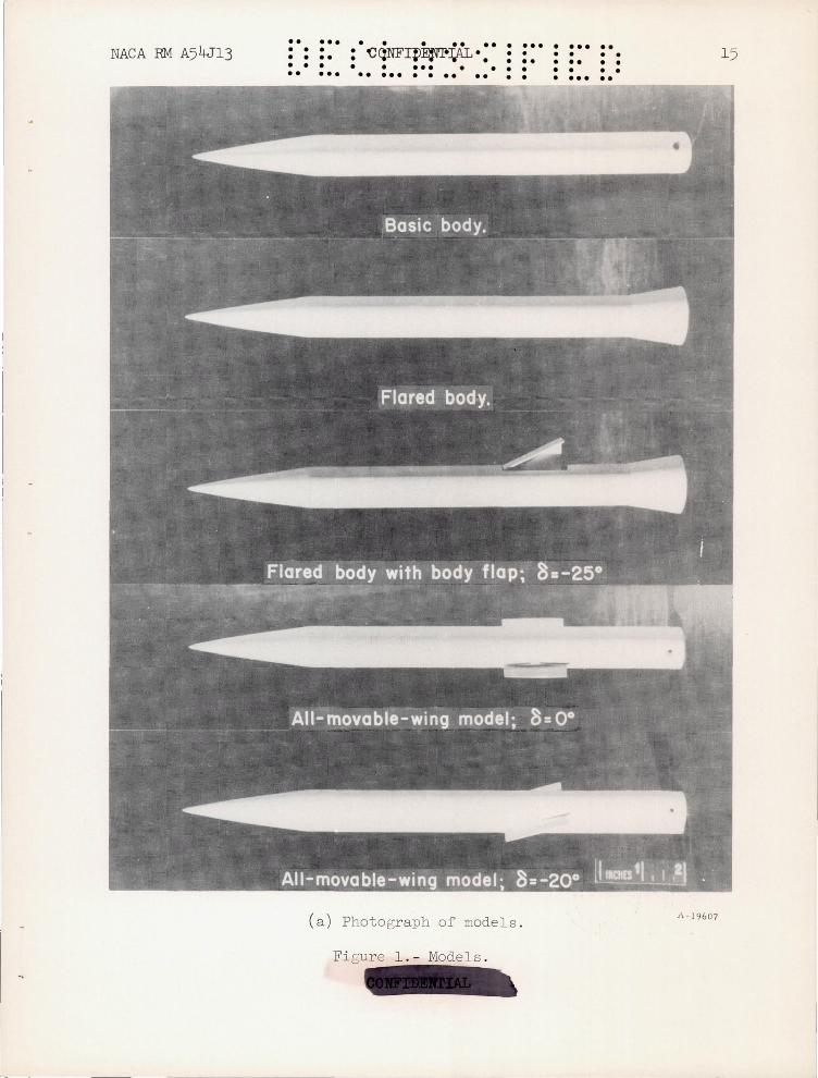
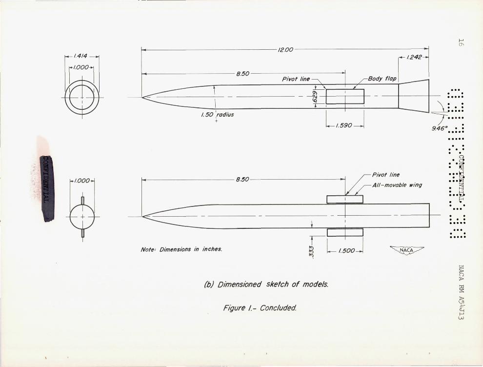
The n:odels tested in the present investigation are shown in figure 1 along with a sketch giving pertinent over -all dimensions. The first model consisted of a l - inch- diameter basic body made up of a fineness ratio 3, 3/4-power nose l faired into a fineness ratio 9 cylindrical afterbody. The second model consisted of the basic body modified by a conical flare at the base. This flare was a frustum of a fineness ratio 3 cone. It extended 1.242 body diameters forward of the base and increased the base diameter by J2. The third model was essentially the same as the second, wi th the exception that a body flap 1.590 body dian,eters long and 780 of arc in circumferential extent was added forward of the conical flare . This flap was ce~tered at a station 8 .5 body diameters from the nose. It had a projected lateral dirr.ension equal to 0 . 629 body diameter and a plan area equal to the square of the body diameter . This particular configu ration was chosen because it .Tas desired to compare the data obtained for the flap with those obtained for an all -movab le -wing model . This latter model, which was tested in the Ames 10- by 14- inch wind tunnel in conjunc tion with a separate research progra~, consisted of the same basic body, with a rectangular plan form, all -movable control of aspect ratio 4/9 (for the exposed panels joined together) . The control was also centered 8 .5 body diarreters from the nose and had the same plan area as the body flap . Tbe chord of the control was equal to 1 . 5 body diameters, and the exposed serispan was equal to 1/3 body diameter . A 4-percent - thick, biconvex air foil section with a O-percent-blunt trailing edge .laS er::plo ed.
lSpecifical1y, this nose is defined by the relation r =~(x/ln)3 4 a:,d
was provide a basic body of lower than average ~ini~um drab (see refs
.. ••• • • . .. •• • ... • ••• .. • • . • • • • • • • • • • • • • • • •• • • • • • • • •• • •• • • • • • • • ••• • • • • • • • • • • •• • • ••• • • •• . . • • • ••• • • NACA RM A54J13 CONFIDENTIAL 5
Neither the body- flap model nor the all-movable-wing intended to represent a practical aircraft configuration. these models provi de experimental results on the relative body- flap configuration .
model is Nevertheless,
merits of the
Accuracy of Test Results
Stream Mach numbers did not vary more than to.02 from the mean val ues of 3. 00, 4 .23, and 5 . 05 . A maximum variation of to.04 existed at the peak test Mach number of 6.25 . Stream Reynolds number for a given Mach number did not depart by more than tlO,OOO from the mean values given in the section "Test Apparatus and Methods ."
The over-all accuracy in angle - of -attack values , including uncer tainti es in the corrections for stream angle and for deflections of the model support , is estimated to be ±0.2° .
Uncertainties in the measurement of forces acting on the models and in the determinat"ion of free - stream dynamic pressures influenced the accuracy of computed force coefficients . At angles of attack up to 100
and Mach numbers up to 5 , these uncertainties resulted in maximum esti mated errors in lift, drag, and normal - force coefficients of ±0 . 015 . A corresponding error of ±0 . 030 is estimated at Mach nun~er 6 . 25 . At angles of attack in excess of 100 , the error increases to ±0.020 at M~ch numbers up to 5 and ±0.045 at Mach number 6 .25 . Pitching-moment coeffi cients are estimated to be in error by not more than ±0.020, except at Mach number 6 . 25 where the value is ±0. 045 . Finally, it should be emphasized that, for the most part , the experimental results presented herein are in error by less than these estimates .
RESULTS A.1I.JD DISCUSSION
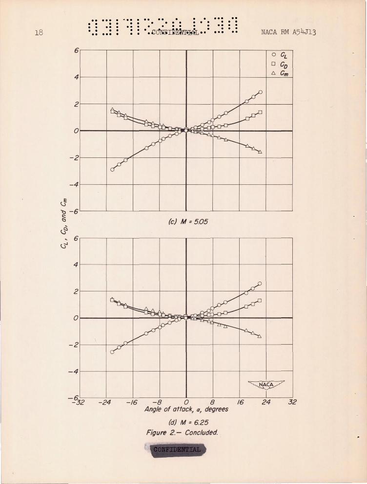
All the experimental data for the three models tested during the investigation are presented in table I . Typical data are also presented in graphicaJ form in figures 2 through 4 . In analyzing these results, it is convenient to consider first the effectiveness of the conical flare in stabilizing the basic body .
Stability of Flared Body
Conical flares sir.:ilar to the one tested here have been investigated previously (see , e . g ., ref. 7), though the intent was not to reduce the
. . ... · ... · .. .. . • • .. . .. • · • • · • • . • • • . • . · · • • .. · .. · • • • • • .. · • • • • • • • • . ••• • · . • · 6 • • ••• · • • · ~o :ru) 'nltL •• • •• •• NACA PM A5 4J13
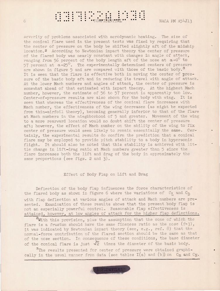
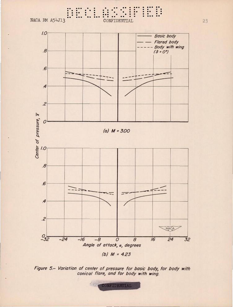
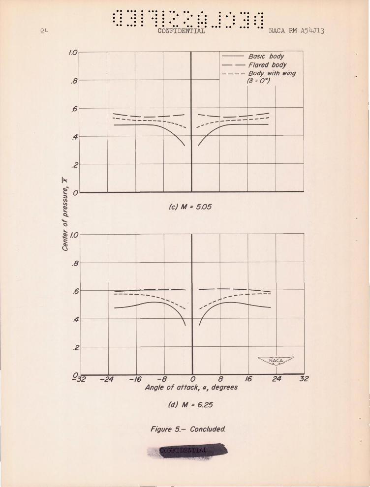
severity of problems asscciated wi th aerodynamic heati ng . The size of the conical flare used i n the present tests was fixed by requiri ng that the center of pressure on the body be shifted slightly aft of the midship location . 2 According to Newtonian impact theory the center of pressure of the flared body was nearly ccnstant with changes i n angle of attack , ranging from 56 percent of the body length aft of the nose at ~ =Oo t o 57 percent at ~=25° . The experimentally determined centers of pressure are shown in f i gure 5 and are compared Id th those of the bas i c body . 3
I t is seen that the flare is effecti ve both in movi ng the center of p res sure of the bas i c body aft and in reducing its travel vTi th angle of attack . At the lower Mach numbers and angles of attack, the center of pressure is somewhat ahead of that estimated '-rith i mpact theory . At the h i ghest Mach number , however , the estimate of 56 to 57 percent is apparently too low . Center- of- pressure results are also sho',TI for the body with wi ng . I t i s seen that whereas the effectiveness of the conical flare increases with Mach number , the effectiveness of the wing decreases (as might be expected from thin- airfoil theory) , becoming generally inferior to that of the flare at Mach numbers in the nieghborhood of 5 and greater . Movement of the wing to a more rearward location would no doubt shift the center of pressure aft j however , the effect of Mach number on the ability of the wi ng to fix center of pressure would seem likely to remain essentially the same . Cer tainly, the experi mental results do confirm the prediction that a conical flare may be employed to provide pitch stability to a body in hypersonic flight . I t should also be noted that this stability is achieved with lit tle change in lift - drag ratio at Mach numbers greater than 5 since the flare increases both the lift and drag of the body in approximately the same proportions ( see figs . 2 and 3) .
Effect of Body Flap on Lift and Drag
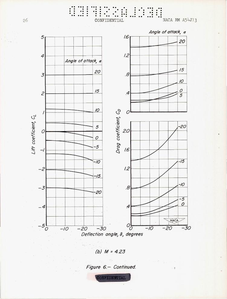
Deflection of the body flap influences the force characteristics of the flared body as shown in figure 6 where the variati ons of CL and CD
with flap deflection at various angles of attack and Mach numbers are pre sented . Examination of these results shows that the present body flap is not an especially powerful control . Reasonable f l ap effectiveness i s attained , however , at low angles of attack for the hi gher flap deflections .
2With this provision, plus the assumption that the ccne of which the flare is a frustum should have the same fineness ratio as the nose (f=3) , it was indicated by Newtonian impact theory (see , e . g . ) ref . 8) tnat the nOrl".al- force contribution of the flared section should be the same as that of the nose section . I n consequence of these conditions , the base d i ameter of the coni cal fla re i s just J2 times the diameter of the basi c body .
3 The results presented for center of pressure were obtained graphi cally in the usual manner from data (see tables I ( a) and (b)) on Cm and eN .
•• . .. .. .. .. • . .. • ••• •• • • • • •• ••• • • • • • • • • • •• • • • • • • •• • • •• • • • •• C~~lf~~1~ .·
• • • • •• • • · • • • • • • • • ••• ... IJACA PM A54J13 7
Evidently, too , this effectiveness is fairly independent of Mach number . At high positive angles of attack the flap is essentially ineffective . On the other hand the flap remains effective at large negative angles of attack . This result suggests that the body- flap control might be most effective in a canard configuration - one, for example, like the nose flap investigated i ndependently by Lazzeroni (ref . 9) at lower supersonic spee ds . The nose flap was designed, however, with a different objective in mind ; namely, it was intended to provide pitch control for a missile air frame having small lateral dimensions . It seems likely, however , that a canard arrangement or , for that matter , almost any arrangement with the flap deflected on the "I,lind"lvard side of the body "llOuld be unstable in roll . Planar f i ns , such as those employed in refe rence 9, wou.ld , of course, pro v i de roll damping . 4 I f stability and control are to be obtained aerodynamically in the absence of planar surfaces, the body flap should be located aft on what is normally the lee side of the body - that is, i n a position sor.cething like the one used in the present i nvesti gat ion . I n this event , hm,rever , the flap doe s not, in the light of the experimental data just dis cussed , appear promis i ng for application at h i gh angles of attack .
Trim Conditions
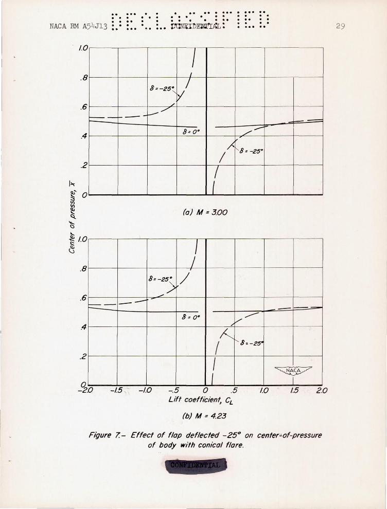
The body flap deflected - 250 influences the center of pressure as shown in figure 7. Results are a l so shown for the flared body with flap uncleflected . By assuming a reasonable static margin, .re can determi ne the trim lift coefficients for the flared body wi th flap over the Mach number range . I f a stati c margin e qual to 3 percent of the body length at a=J o is taken and the results of f i gure 7 are used , these l ift coefficients are found to vary with Mach number as shown in fi gure 8. Vari ation of the correspondi ng coeffici ents for the model with all -movable vring deflected - 250 i s also shown . It i s seen that the lift coeffici ents at tr im for the body- flap model increase steadily with Mach number . In contrast to thi result , the trim lift coeffi cients for the model wi t h all -movable wing decrease markedly with Mach number, falling below those of the body- flap model at the highest Mach number .
The lift - drag ratios corr esponding tc these trim lift coeffi c i ents are shoT,TD in figure 9 for the two configurations . The trends observed in the lift - drag rati os also favor the body- f l ap model at the hi gher test Mach numbers . 5
4While the addition of such fins may present no problem at l ow super sonic speeds , their a ddition woul d l ead to aerodynamic - heat ing problems at tigh supersonic speeds , tending to defea~ the advantage sought here with the present body- flap confi gurati on .
5The maximum trim lift - drag rati os attainable with each control at the various test Mach numbers might make a better compari son . However, due to the limited number of control deflections tested in the present investiga-tion , i t was not possible to determine guanti t i es accurately .
•• ••• • ••• •• •• • ••• •• 8
. . . · • 0 0 00 0 00 0 . • • • · • • • ••• • • •
. ... . 00 CO I~TI ~ •• • ••••••
. • • • • 0 00 0 0
• 0 0 0
•• •• • • • NACA RM A54J13
Up to now we have considered, so to speak, only the gross effects of a conical flare and body flap on the aerodynamic characteristics of a body of revolution . In the interests of better understanding how these devices inf~uence flow about the body, it is appropriate next to discuss results of flow visualization studies .
Flow Visualization Studies
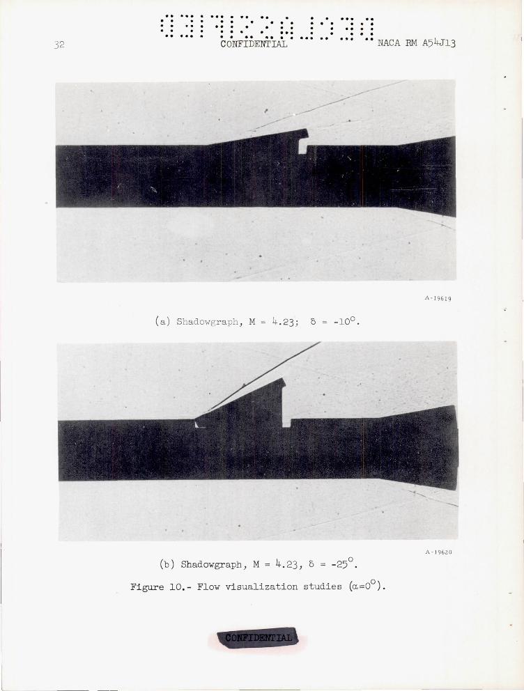
Two types of study were made . First, shadowgraph pictures were taken of the flow in the region of the flap and flare at Mach numbers of 4.23, 5 . 05, and 6 . 25 . The model was set at 00 angle of attack with flap deflections of - 100 and - 250 . (Note the rrodel was moved downstream in the tunnel to perrrit the taking of these pictures . ) Second, the flow at the surface was observed at a Mach number of 4 . 23 using the China- clay technique6 (see, e . g . , ref . 10) . Typical results of these studies are pre sented in figure 10 . It is indicated by the shadowgraph pictures that the shock wave produced by the flap has caused only moderate thickening of the boundary layer forward of the flap . The China- clay pictures verify this point and show further that the boundary layer tends to bleed around the sides of the flap from the high-pressure region on the top to the lowpressure region below and behind . Much the same phenomenon has been observed in studies of boundary- layer flow over ramps in front of inlets (see ref . 11) . Accordingly, shock -wave -boundary- layer interaction would not appear to play an important role in the performance of the body flap, at least at intermediate to large angles of deflection .
The flow aft of the flap is apparently separated, however, as is strikingly indicated by the absence of a strong shock wave emanating from the upper part of the conical flare (see figs . lO(a) and (b), M = 4 . 23) and by the streanline pattern in the China- clay pictures . This flow separation may be expected to reduce the forces on the tail cone and should, of course, be considered in any calculation of flap effectiveness .
With these points in mind, it is undertaken next to determine how well flap characteristics can be predicted by theory .
Comparison of Theory and Experiment
A limited number of calculations have been made to estimate the incremental force coefficients due to flap deflection . Both impact theory (ref . 8) and the generalized shock- expansion method (refs . 12 and 13) were
6 It was not possible to obtain results for the higher test Mach nu~ bers because the drying time of the fluid used in the tests was less than the time required to establish flow at these Mach numbers .
~w
I
.. . .. . • • • • •• • • • • • ••• • • • • .. NACA PM A54J13 • • • • • ·C ~NFI1)m'r~AL· • • • • • • • • • • · • •• • •• • • • • •• . •• ... • · · • • • · • • • •• • • •• • • • • • ••• ••
employed .7 In these calculations, the interference of the flap on the flare was determined by considering , as prescribed by impact theory (see ref . 8), that no forces act on any part of the body shadowed from the free stream by the deflected flap .
9
The results of the calculations are compared with those of experiment in figure 11 for the test Mach number of 5 . 05 and angles of attack +100 , 00 , and - 100 . The predictions of both theories are generally in from fair to good agreement with the experimental results at angles of attack of 00
and _100 . 8 At +100 angle of attack , only qualita tive agreement is obtained with ei ther theory ( impact theory gives zero force increments since the flap is always within the shadow of the forward part of the body) . Evi dently, then, neither theory properly accounts for the fact that the flap is oper ating largely in the wake of the body .
The effect of flap - flare inter ference on incremental lift coefficient is illustrated at zero angle of attack in figure ll (b) where results are shown for the coefficients calculated with impact theory neglecting inter ference . Comparison of these results with those including the interference indicates that the shadow concept of impact theory is adequate in this case for predicting the interference effects . These results also show that the interference has a significant detrimental influence on flap effectiveness . Recommendations for elimination of this influence will be discussed later .
CONCLUDING REMARKS AND FUTURE DESIGN CONSI DERATIONS
Results of the experimental investigation of a body of revolution having a conical flare at the base to provide stability in pitch and fitted with a body flap to provide control in pitch have been analyzed at Mach numbers from 3 to 6 . 25 . It was found that these devices do , in fact , per form their intended function at high supersonic airspeeds . In particular , the conical flare was effective in fixing the center -of-pressure location slightly aft of the midship point on the body at Mach numbers in excess of 4 and angles of attack up to 250 . The body flap improved as a trim device over the Mach number range of the tests . At Mach numbers in excess
7The initial condi t i ons for the shock- expansion solutions were deter mined from pressure distributions ( and shock waves ) measured for a cone having a semi vertex angle of 18 .930 . (These data were obtained in conjunc tion with an independent series of tests in the 10- by 14- inch supersonic wind tunnel.) The use of this procedure means , in effect , that for the purposes of these calculations , the blunt nose of the body was replaced vii th a cone tangent to the 3/4-power profile at 1. 77 percent of the nose length .
sOne exception, that for the incremental lift coefficient at ~~ -100 and 5~ - 100 , is noted . Although the cause of this difference between theory and experiment is not known, it is believed that it is due to a more ext ensive and interference t han considered b the theories .
---------- ------~---------------------------------. -----.----
10 •• ••• • ••• • •• •• •• .... . .. ••• • • •• •••• ••
•• •• • • • ••• ••• o °CO~I OOr:TIAt •• • ••••••••
... .. 000
o 0 o 0 0
••• •• l~ACA PM A5 4J13
of about) , the cO~:lbination of body flap and conical flare became superior to an all -movable wing , providing larger tri . lift coefficients and larger trim lift - drag ratios at a control deflection of -250 • These results offer encouragement to the possibil i ty of designing stable and controllable hypersonic aircraft essentially free of planar surfaces which present inor dinately severe aerodynamic - heating problems .
ExperimentalJy determined increments in lift and drag due to flap deflection were compared at a Mach nu ·~oer of 5 to the predictions of both the generalized shock- expansion method and the Newtonian impact theory . The predictions of both theories were found to ce in fair to good agree ··~ent with experin_ental results at small angles of attack . In the appli cation of the theories , it was found that consideratio~ ~u st be given to the interference of the flap on the conical flare . This finding was brought out and supported by a series of visual studies of the flow in the region of the flap and flare .
In general , the ef~ectiveness of the flap as employed in ttese tests ... ras found to be 1m-I at small flap deflections and , more or less irresper. tive of flap deflection , at l arge positive angles of attack (in he ne igh borhood of 20 0
) . It seems unlikely that flaps of this type located on the lee side of a body offer mu t promise of being made effective at large angles of attacl~ , inasmuch as under these cir wnstances the flap is largely submerged in the wake of the body . Flap effectiveness for small flap deflections may , however , be improved over that obtained in the pres ent tests by locating the flap on a positively inclined surface rather than on the cylindr i cal afterbody ) su h as was done here . The oni al flare provides a logical surface for this purpose since this location 01' the :lap will have the added advantage of eliminating the unfavorable efr'ects of fl ap - flare interference . The resulting configuration might appear some thing like that shown in figure 12, though , of ourse , many variations are possible . This conf i guration has the same over - all fineness ratio as thL test body of this report , but it has a more slender nOS L and stabilizing cone . This modification should , of course ) increase the attainable lift drag ratios (s ee ref . 4) . The body flap could be employed in pairs rather than Singly , thereby permitting an in rease in over - all effec tiveness at small and intermedi ate flap deflections by allowi ng the lower or v.rindward f lap to be retracted into the flare while the l eeward fl ap is extended away from the flare . Retract i on of the lower or v.rindv.rard flap would , in effec t , reduce the stabilizi ng effect of the tai l cone and thereby permit a further increase in trim l i ft . It is noticed , too , that a pair of yaw control flaps has been incorporated in thi s design , the assumpti on being that if the body flap i s effective i n pitch , it should a l so be effective in yaw .s I t is ~ of course , a logi a l extension of this control to .ons i der the all -movable tail cone . Also , it is observed that some stabil i ty
s Simultaneous deflection of all four flaps would also provide a method of control ling the body center - of -pressure location and , hen e , controlling the stability of the onfiguration .
--- - - - --------"
•• • •• • • • • • •• • • •• • ••• •• • • • • • • • • • • • • • • • • • • •• • • • • • • • •• • • • • • • •• • • ••• • • • • • A54J13 •• . .. • • Ct1N"F:rDl:N~AL" • • • • NACA PM · · · ••• .. II
in roll shoul d be provided by the extended flap . These possibilities must , of course , be investigated experi mentally to determine the extent to which they can actually be realized .
Ames Aeronautical Laboratory National Advisory Committee for Aeronaut ics
Moffett Field, Cali f . , Oct . 13, 1954
REFERENCES
1 . Sanger , Eugene : Raketen- flugtechnik . R. Oldenbourg (Berli n) , 1933, pp . 112, 120- 121 .
2 . Resnikoff , Meye r M.: Opti mum Lifting Bodies at Hi gh Supersonic Airspeeds . NACA PM A54B15 , 1954 .
3 . Denni s , Davi d H. , and Cunningham, Bernard E. : Forces and Moments on Poi nted and Blunt- Nosed Bodies of Revolution at Mach Number s From 2 . 75 to 5 . 00 . NACA RM A52E22, 1952 .
4 . Dennis, David H., and Cunningham, Bernard E.: Forces and Moments on I nclined Bodies at Mach Numbers From 3 . 0 to 6 . 3 . NACA RM A54E03, 1954 .
5 . Eggers, A. J . , Jr . , and othwang, George J .: The Ames 10 - by 14-I nch Supersonic Wind Tunnel . NACA TN 3095 , 1954 .
6 . Eggers , A. J . , J r . , Dennis, David H. , and Resni koff , Meyer M.: Bodies of Revolution fo r Minimum Drag at High Supersonic Airspeeds . NACA RM A51K27 , 1952 .
7 . Ross , F. W., and Dorrance , W. H.: An I ntroduction to a Supersonic Body Development Study . Univ . of Mich ., Engi neering Research I nstitute , UMM- 40 , Dec . 1949 .
8 . Grimminger , G. , Wi lliams , E. P . , and Young, G. B. W. : Lift on I ncli ned Bodies of Revolution in Hypersonic Flow . Jour . Aero . Sci ., vol . 17, no . 11 , Nov . 1950, pp . 675 -690 .
9 . ,Lazzeroni, Frank A.: I nvestigation of a Missile Airframe with Control Surf aces Consisting of Projecting Quadrant s of the Nose Cone . NACA RM A53L21 , 1954 .

•• ••• • ... • •• • • • • • • · • .. · .. · • • • • • • •
•• • • • • • • •••
• • • • · • ••
• • • ••• • • • • • ....
• • • •• • • • 12 NACA RM A54J13 •• ••• • • • • CONic·IDENTiAi
10 . Gazley, Carl , Jr .: The Use of the China-Clay Lacquer Technique for Detecting Boundary- Layer Transition . Gen . Electric Co . , Schenectady, N. Y. Gen . Engineeri ng and Consulting Lab . Rep . 49A0536, 1950.
11 . Davis , Wallace F . , and Goldstein, David L.: Experimental I nvesti gat ion at Supersonic Speeds of Twin- Scoop Duct I nlets of Equal Area . I - An I nlet Enclosing 61 .5 Percent of the Maximum Circumference of the Forebody . NACA RM A7J27, 1948 .
12 . Eggers , A. J ., Jr .: On the Calculation of Flow About Objects Traveling at High Supersonic Speeds . NACA TN 2811 , 1952 .
13 . Eggers , A. J ., Jr ., and Savin, Raymond C.: Approximate Methods for Calculating the Flow About Nonlifting Bodies of Revolution at High Supersonic Airspeeds . NACA TN 2579 , 1951 .
l ___ _
l

•• . .. . • • •• .. • . .. • ••• • • • • • • • • • • • • • • • • • • • • •• • • • • • • • •• • •• • • • • • • • ••• • • • • • • • · •• • •• • ·CONFIDE·NTIAL· · • • • ••• •• NACA RM A54J 13 13
TABLE I. - FORCE AND MOMENT CHARACTERISTICS
(a ) Basic bod,y (b) Flared bod,)': 6. 0°
M n CL CD CN c" M n CL CD CN Cm M n CL CD CN Cm M n I-
CL CD CN Cm
3.00 0 0 0 . 146 0 0 5 .05 0 0 0 . 10h 0 0 3.00 0 0 0 .210 0 0 5 .05 0 0 .163 0 0 2 .03 . 102 .158 .108 -.031 2 .01 .120 .il6 .12' - .039 2 .04 .1"8 .281 .158 -.070 2 .01 . 18? . 189 .190 -·097 2 · 91 .167 . LIl4 .176 -.049 2 .89 .230 .132 .236 -. 105 2 · 91 .222 ·297 .237 -. liO 2·90 .326 .204 .336 - .19" h.91.i .3il .195 .327 -.104 4.90 .b01 .164 . h14 -. 172 ' .95 . 396 · 310 . 421 -.196 ' .91 .564 .23' .581 -·330 6 .96 ·520 .223 . 5411 -.187 6.91 .632 .213 .653 -.293 6 .99 .630 .326 .665 -· 317 6 .92 .825 .292 .85' - .b80
10 .06 .984 ·332 1.021 -. 420 7 .90 . 771 .2 43 .797 - .369 10 .08 1.ll2 . '60 1.116 -·557 1 ·91 .922 . 352 .961 -. 514 13 .19 1 ·5411 ·520 1.622 -. 724 9 .91 1.032 ·325 1 .072 -. 509 13 .22 1.738 .659 1.842 - ·923 9 ·93 1.209 .451 1.269 -.673 17 .64 2.400 .914 2 .56' -1.197 11.93 1.308 . 431 1.368 -.660 17-69 2 ·723 1.114 2 .951 -1.561 il ·95 1.525 .587 1.613 -.871 20.78 2 ·995 1 · 310 3.265 -1.570 lB .22 2.212 .936 2.394 -1 . 120 20 .85 3.384 1.652 3.751 -2 .061 18 .24 2 .6C)l 1 .0112 2 .791 -1.511 2, .00 3·820 1.981 '.300 -2.125 20 .25 2·552 1.15L 2 .79" -1. 326 24.01 4.058 2.128 ' . 567 -2·573 20 .26 2.997 1.333 3·273 -1.823
22 .28 2 .903 1 . 412 3·222 -1 .558 22 · 30 3 .416 1.729 3.816 -2 .156 4 .23 0 0 . il' 0 0 ' .23 0 0 .207 0 0
2 .02 .il3 .122 .il7 -.ObO 6 .25 0 0 .il7 0 0 1.01 ,078 .2il .082 - .044 6 .25 0 0 .140 0 0 2.90 .129 . 139 .195 -.066 2 .00 .108 .126 .1l2 -.040 2 .02 .151 .216 .158 -.078 2.00 . 191 .155 .211 _ . 121 4 .92 .352 . 1511 .3611 -. 134 2.88 .189 .133 .196 - .083 7·95 .887 .326 .92' - . 4"2 2.89 . 316 .r', .326 _.224 6 . 94 ·609 .197 .629 _.2-'4 4.89 .375 .172 .388 - .189 9·99 1.183 . 419 1 .23" -.628 1;.89 .532 .20' ."'9 -.342 7 .9' ·755 .22- ·779 -. 341 6 .89 .528 .2il .549 -.257 12 .03 1 .5l2 .546 1.593 -.82' 6 .90 30 .256 .756 - ·'5' 9 ·9' 1.033 .310 1 .011 -. 482 7.87 .722 .235 . '47 - .368 lB.41 2 .105 1 .168 2.944 -1.632 7 .88 1.039 .297 1.070 -.650
12 .01 1 . )28 .'18 1 .385 - .63' 9 .88 .951 ·290 .987 - .504 20.41 3.098 1 . 461 3 . 41, -1.898 18 .03 2 .376 1.201 2 .631 -1.546 18 .38 2 ·333 .934 2 .509 -1.206 il .29 1.181 · 390 1.237 - .653 22.52 3.508 1.190 3.906 -2.179 20 .15 2.715 1.'75 3·056 -1 .814 20. 44 2 ·698 1 .173 2 .938 -1.43' lB .13 1.888 .826 2 .052 - .939 22.16 2.907 1.759 3. 356 -1.29' 22 . 49 3.041 1.440 3.360 -1.657 20 . 14 2.202 1 .040 2 . 425 -1.150
22 .1, 2.564 1 . 319 2.872 -1.389
(c) Body- flap model; & • _100 (d) BodY- flap model; & • _250
M n CL CD Ow c" M n CL CD Ow Om M n CL CD CN Cm M n CL CD C. c"
3 ·00 - 24.01 - 4 . 024 2.260 -' .595 2·513 5 .05 - 22 · 30 -3·387 1.902 -3·856 2 .131 3.00 - 211 .09 - 4.118 2.781 - 4 . \9:) 2.655 ' . 05 -22 .32 -3·546 2 ·523 - "
2391
2'339 - 20. P5 -3·3"8 1 ·102 -3. 735 1.969 -20.21 -3.007 1.563 -3·363 1.847 -20.92 -3.540 2. 129 _4. 081' 2.201 -20.29 -3· 246 2.183 - 3.802 2.108
-11.68 -2.687 1.~0 - 2 .940 1 ·521 - 18 . 24 -2.628 1.269 -2.293 1 .580 - 11 · ~ - 2 · 929 1.701 -3·310 1.76' -18. 26 -2.930 1.864 - 3·367 1.873 - 12 . 11 -1. 545 .670 - 1.651 ·798 -11.95 -1.548 .640 - 1.641 .876 - 13 · 21' - 2.033 1.151 - 2 . 245 1 . 181 -11.91 -1.938 1.066 - 2 . 117 1.200 - 10.08 -1.117 ·531 -1.193 .541 -9.92 - 1.212 . '99 -1.2IlO .661 - 10 . 14 - 1.424 .886 -1.558 .803 -9·95 - 1.614 .863 -1.739 .983
.00 -. 747 · '38 - .801 · 331 - 1.91 -. 928 .390 -. 972 .'96 -7 .06 -.989 .725 - 1.011 .592 -7.93 - 1.311 ·101 - 1.3951 .802 -7 ·00 - .633 .'22 -.679 · 307 -6 .92 - .826 . 344 -. 862 . '75 -5 · 01 -. 760 .659 -. 815 .459 -6 .94 - 1.213 .611 - 1.219 .782 -4.95 -· 395 .387 - . 421 .180 - ' .91 - ·560 .289 -. 5~3 .320 -2.98 - .591 .617 -.622 · 378 -4·93 -.920 .512 -. 960 .602 -2.92 -. 232 .380 - ·251 . 102 -2 ·90 -. 329 .244 - .341 . 197 -2.12 - .523 .57' -. 544 .3'9 - 2 ·91 - .678 . 4~)l -· 100 . 463 - 2 .a, -. 172 ·3'3 -. 184 .067 - 2 .02 - .169 .224 -. 176 ·057 -1.09 - . 449 ·561 - . 459 ·312 - 2 . 03 - .544 .'bA -· 559 . 400 - 1.03 -.096 ·330 - . 102 .030 - 1.01 - .LOI .214 -.104 . 032 - .07 - ·367 .544 -· 368 .266 - 1.03 -. 455 . 412 - .462 · 351 0 - .026 · 323 -. 026 -. 002 0 - .018 .192 -.018 -. 006 . 95 -. 292 ·530 -. 283 .230 - .02 - .344 .368 -. 3114 .282 l.01 .049 · 321 .054 -.0]1 1.01 .083 .199 .087 -.060 1.98 -. 198 .513 - . 180 .171 · 99 - .212 ·35' - .206 .197 2 .03 .120 ·322 : ~~
- .069 2 .01 · 112 ·205 . 179 -. 1().4 2.86 - .125 .524 - .099 .066 2.00 - .097 .341 -. 08, , 110 ' .9' · 353 .359 - .173 2.89 .289 .227 .300 -. 166 4.90 .069 .506 . 112 .026 2.88 .038 · 346 ·055 .013 6 .98 .562 ·379 .603 - .278 4 .91 ·500 .256 .521 -. 280 6.91 ·300 .524 · 361 - .089 '.90 ·302 .343 · 330 - . 141 7·99 .681 . 1101 · 731 -. 316 6.92 .768 ·307 . 799 -· 1i34 10 . 01 · 791 .616 .886 -. 380 6 .91 ·590 ·375 .631 -· 308
10 .07 1.071 .490 1.140 -.545 7.90 .904 ·321 .939 -. 492 13 ·17 1.514 .792 1.654 -. 829 9·92 1.115 . 480 1.182 -.642 12 . 16 1.502 .607 1.597 - . 794 9 .92 1.202 . '30 1.258 -.67' 17-65 2 .630 1 . 264 2.890 -1.556 11.94 1.412 .595 1.563 - .863
11 . 94 1·521 .567 1.606 - .814 20.81 3·290 1.683 3.673 - 1.995 18.24 2.631 1·301 2.906 - 1 .6'3 4 . 23 -22 .53 -3·'93 1.902 - 3·955 2.190 23·98 3·933 2.136 4 . 461 -2.434 20 ·27 3· 027 1.591l 3·393 -1.939
-20.'7 -3·117 1.570 -3·469 1.9111 6 .25 -22 . 16 -2.929 1.749 -3·373 1.864 22 . 21 3.40' 1.923 3. 1119 · 2 .235 - 18 . 42 -2.141 1 . 284 -3·012 1.658 - 20 . 111 -2.593 1.4C>e -2.917 1.626 4.23 - 22 ·51 - 3·738 2.539 - 4 . 427 2.411 - 12.03 -1.539 .620 - : .6)8 .831 - 18 . 13 - 2 ·211 1 . 120 -2·513 1.387 - 20.51 - 3.339 2. 183 - 3·293 2 . 152 6.25 - 22.16 -3.092 2 . 415 - 3·775 2.135 -9.99 - l.213 . 481 - 1.278 .639 - 11.89 - 1.1102 .60' - 1.'97 .827 - 18 . 45 -2.978 1.838 - 3. 401 1.886 - 20 . 15 - 2 .181 2.062 - 3·321 1.903 - 7.95 -.904 .384 -.9'9 . 466 -9.88 - 1.109 .466 - 1.112 .626 - 12 . 08 - 1.915 1.023 - 2.087 1.156 -18.14 -2.508 1.162 - 2 .932 1.683 -6.95 - .626 ·350 -.664 .284 -7.87 - .818 ·361 -. 860 . 429 - 10.03 -1.'76 .837 -1.697 .940 - 11.91 - 1.621 1· 052 - 1.999.1.227 - 4·93 - . 4511 .285 -. 477 · 227 -6.90 - . 714 .265 - .7110 . 413 -7 .99 -1.247 . 690 = i : r~~
.741 -9.90 - 1.514 .831 - 1.614 1.009 - 2 ·91 - .282 . 267 -·296 . 149 -4.29 - . 491 .209 -.508 .285 -6 .99 - 1.11' .623 .696 -7. 29 - 1.214 .656 -l.292 .817 - 2.03 - .186 . 243 -. 194 .085 -2 .29 - .318 .197 -· 327 .212 - ' .96 - .817 .539 - .860 .,14 -6 .91 - 1.136 . 612 - 1.202 .169 - 1.02 - .100 . 239 -. 105 .041 - 1.00 -. 111 . 169 - .lJ4 .060 -2.9' -. 625 . 484 - .6'8 . 414 -4.90 - .913 ·503 - ·953 .6"8 0 - .016 .238 -. 016 -. 003 0 -.017 . 153 -. 011 .007 -2·01 - .524 ."85 -.541 · 357 -2 ·29 - .6"8 . 409 -.668 . 471 1.01 .067 .241 .072 - .048 1.00 .07"' , 161 .082 - .046 -1.0} -. 431 .461 -. /0/05 · 309 - 1.00 -· 387 · 331 - ·393 .347 2 .02 .142 .245 . 1,0 -. 081 2.00 .177 .186 .184 - .076 -.04 - . 341 . '39 - . 341 · 253 0 -. 26' .293 - . 264 .273 2·90 .233 .258 .246 -. 128 2.29 .287 . 196 .296 - . 194 .98 - .239 . 410 -. 232 .193 1.00 -. 1l6 ·277 -. 111 .169 ' .92 .401< .266 .'27 -.209 4.89 .482 ·227 .,00 - .298 1.99 -.140 . '09 -. 126 . 137 2.88 , 140 .241 .153 -· 025 6.95 .678 . 3°4 . 110 -· 369 6.90 .703 .281 ·131 - · '33 2.88 -.01<7 .'05 -.026 ·077 4.29 · '27 .222 . 445 -.202 1.9/0 .876 · 311 .902 - . 463 7.00 .843 . 267 .872 _. 4114 '.90 .160 ·385 . 193 -.026 6.90 .675 .27' . 703 -· 362 9.9!' 1 . ... 15 .'39 1.1/04 - .547 9.29 1.101 ·372 1.149 - .610 7.92 .635 · '35 .689 -. 314 7·87 .B14 · 338 .852 -. 481
12.02 1.'53 ·551 1.'1' -. 774 9 ·97 1.009 ·509 1 .082 -·5'9 9 .88 1.057 . 415 1.112 -. 639 12. 01 1.393 .615 1.1.91 -. 779 11.29 1.4)0 .538 1.'08 - .836 IB.41 2 .691 1.229 2.961 -1. 664 IB . 13 2 · 310 1.135 2.5'9 - 1.509 20. 46 3·090 1.555 ).439 - 1.939 20 . 14 2.660 1·292 2.942 · 1.13) 22 .52 ).490 1.877 3·9'3 -2.233 22.16 3·023 1.532 ).378 - 1.949

· ... • • • • • . •• • •• .. ••• • • • • • • • • • • • • • • · . . . • • • •• • · • .. • .. • • • . • • • • • • • • ••• • 14 ··coMr!) 11h ·· ••• ••
A5 4J13 •• ••• • • NACA RM
•• NACA RM A54J13 • • • • • • ••
• •• • •• • • • •
•• • •• • •• : ~ C:NFII>~J;AL · • •
•••
• ••• • • •••••••• •• · . • •• • •• • •
(a) Photograph of models .
Figure 1 .- Model s .
• ••• • • •• •• ••• •• •• • • • •••• •
A -19607
15
~oo 1 1
1.242
I . 8.50 . ' Pivot line --.... I r-Body flop
" L5 I I - -~ I I • ~,
I •
1.50 todlus +
I
. 8.50 I / Pivot line .. / r-AII- movoble wing
"<'" - - ----
Note: Dimensions in inches. ~
(b) Dimensioned sketch of models.
Figure I. - Cone/uded
l_
f-' Q\
... • • •••••
~ .. • •• • ••••
) .... : 9.460
•• ••••• • •••• . • •• • • o :' . ~ .:.~ ••• F.l · ~ : .. ~ • ... • • • • •••••
••• • •••••
~ ~
~ (;; e-f-'
l.U

BW
I -
•• • •• • • • • ••• •• • •• •• • •• ••• • • .. :-0 • • • •
NACA RM A54J13 • • • •• • •• • • •• • • • •• CWVlP)~w.r~ • • • • •
•• • • • • •
••••• • •• •• •• • •• •••••
6
4
2
o
-2
-4
4
2
o
-2
-4
o CL
o Co 6. Cm
/ ~
"'" ~
~ , ~ /
~
~ ~ -"" ~
~ ~
~ / ~
/ IU
Cf
(a) M = 3.00
/ ~ ~ ~ ~ y
"Uo.j ~ r= ~
r ~ ~ V ~ /
~ I
-24 -16 -8 0 8 16 Angle of attack, a, degrees
24 32
(b) M = 4.23
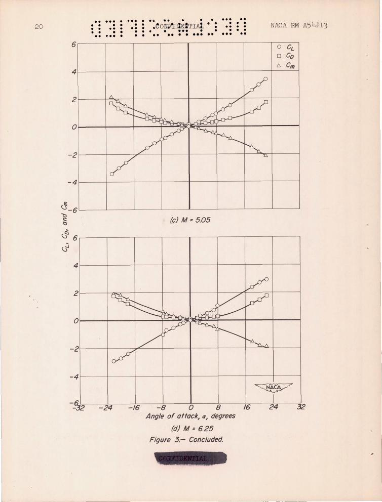
Figure 2.- Force and moment characteristics of basic body.
17
18
J'
•• ... • • • • • • 0 00 0
• • • • •• ••• •
6
..... . • • • 00 · • • • •
•• •• • •• ••• • • • ••• • •• ••• . . .. . . . ... ·.c~~~~ •. · •. : -.: NACA RM A54J13
o CL
o Co 4 r-__ -+ ____ ~----+_----~--_+----~----+_~~C~m~
-4~---+----~----+---~~---+----~----+---~
~ _6L---~-----L----~----L---~-----L----~--~
§ (c) M = 505
& .. 6 ~
4
/
~ ~ ,/V
~ A ~ /
~ l"I-n..
V V ~ ~ ~
\ rY"
c?
2
o
-2
-4
~ f
-16 -8 0 8 16 24 32 Angle of attack, a, degrees
(d) M = 625 Figure 2. - Concluded

NACA RM A54J13
6
4
2
o
-2
-4
4
2
o
-2
-4
~~
•• • •• • • • • ••• • • • •• • ••
• • ~ciNFI!)~." · : : .. : : •• : • • • • •• • a ••• ••• • • • • ••• • • •• •• •• .. ... . ... .. .. . .. , ..
/ V, ~ ~ ~ V
1- ~ ~~
~ ~ ~ L ~ /v ~~
(a) M= 300
A V ~ ~ ~ ~ V
-h
~ ~ ~ / ~
/ -n
o CL
o Co 6. Cm
~ -ffi -8 0 8 ffi
Angle of attack, a, degrees
(b) M =4.23
I 24 32
Figure 3.- Force and moment characteristics of body with conical flare.
19
20 •• ••• • ••• • • • • • • • • • •• • .. • • • • • • • •• ~ .. • • •
6
•• •• • • • .eomtI:1lEfiIAt •
• • ••• • •• •• • • ••• •• • • •
••• • • • •• •••• • • • ••• • • NACA RM A54.r13
o CL
o Co 6. em
4~--~----~-----1----~-----+-----+-----+----~
2~----~~--~----~------~-----r--~~------~--~
-2~----~-----b~--~------~-----r-----+--~~~--~
-4 ~----~----~----+-----+-----+-----~----~----~
G_6L-____ L-____ ~ ____ _L ____ _L ____ ~ ______ L_ ____ ~ __ ~
§ (c) M = 5.05
~ 6 .-----.------.-----.------r-----.------.-----,,-----.
4 ~----r-----~----~----+-----+-----+-----~--~
2~----~~--~-----r----~-----+----~~----~--~
-2~----r_--~~---1----~----_+----_+--==~----~
-4 ~----r_----r_----~----+_----+_----+_----+_--~
Angle of attack, a, degrees
(d) M = 6.25 Figure 3.- Concluded.

NACA • • • •• •• • • •• • ••• •• •• ••• • • • • • • • • • • • • • • • • • · • • • •• • • • • • . •
54J13 • • •• VCOO'IllEm"DtL : • • • • RM • • • • • • ••• •• •• ••• •• •••
6 o CL
o Co t::,. Cm
~A. V '0... ~ k V
Ir.L,-,
~ \1\" ~ JY
b~ pY~
~ / ~
/ V ~
4
2
o
-2
-4
G "t3 -6 § (a) M =300
'-:l~ ~ 6~--~----~----~----~----~----~--~-----.
~
4~---1-----+----~----~----+-----r---~----~
~ -6~--~----~--~----~--~----~--_~1--~ -32 -24 -16 -8 0 8 16 24 32
Angle of attack, a, degrees
(b) M = 4.23 Figure 4.- Force and moment characteristics of body with conical flare
and flap deflected -25~
- -
21

22
6
4
2
o
-2
-4
.. ••• • • 0 • • ••• ••• •• • •• • ••• · • •• · 0 .
00 .00
0 0
0
• • ••• •• • •• ••• °COV!D$1-b-A·: ° 0: 0.: 0:: :. : NACA RM A54J13
o CL
o Co 6. em
~ V ~
~ ~ V ...a:
'"""--"-'l ~
V 'f:Y ~
~ / ~ V "U
/ l:
U-6 "t)
§ (c) M = 505
~ 6~--~----~----~----~----~----~--~-----.
4~--~-----+----~----~----+-----r---~r---~
O~--~-----+-----r----~~~+-----r---~------
-2r---~-----+~~-r----4-----+-----r-~~----~
-4 r---~-----+-----r----4-----+-----r---~----~
-16 -8 o 8 Angle of attock, Q, degrees
(d) M = 6.25
Figure 4.- Concluded.
16 24 32
. • • . . •• • ... • ••• •• • •• • · • · . • · · • • • • · . • • • • • • • •• • · • • •• • • • • • • • • • • • • • • • • • • ••• • • • ••• .. •• • • • •• ••• • • .. •• NACA RM A54J13 CONFIDENTIAL
1.0 Basic body -- Flared body
.8 - - - - - Body with wing
(8 = 0°)
.6
.4
~-....:.. f--- __ --::;;::- ..::::--.....-:::-: ---r-:-::.: ---f- __ ::.- -L :.---- -~
~ '", /
.2
I~
(0) M =3.00
.8
.6 ::--:::--:.:-: --~- 1---= ~---t----::::: ---- ------ r----.. ./ t.----
'" / .4
.2
~ 1
~32 16 24 32 -24 -16 o -8 8 Angle of atfackl a
l degrees
(b) M = 423
Figure 5.- Variation of center of pressure for basic bod~ for body with conical flarel and for body wi th wing.
23
24
•• ... • ... · •• • • • · . • •• • • • • • • • •• • • • • • • • • • · • •• • • • • • • • • • • .. • • • • • • • • • • •• • • • • • • •• ... • • • •• .. • · ... .. . .. • • CONFIDENTIAL NACA RM A54J13
1.0 Basic body
- - Flared body - - - - Body with wing
.8 (8 = 0°)
.6 ::::::------f--- -- ---I----------- --- ~~-;;
-----.........
"" '- r-
~ / .4
.2
Ill(
(c) M = 5.05
.8
---- ---- --- -----. ... .6
R ~ -........
'/ -r--- .......
\ I .4
.2
~ I
-24 -16 -8 0 8 16 24 32 Angle of attack, a, degrees
(d) M = 6.25
Figure 5.- Concluded

~W
I -
• • • •
.. ... .. . .. . ..... • •• ••• ••• • •• •• • • •• • • • •• • • • ••• • •••
• ••••• .. .. NACA RM A54J13·· • • • •••••• c!OMIDENTID
• •• •• •• •• • •••••
(,,)...J
~ ... c::: .~ . (.J ~ -....: <l.I () (.J
.:t:: ...... -...J
5 /.6
4 12 Anq/e of attack, a
- 20 3 .8
I
0
-I
-2
-3
-4
-5 o
-
-10
- r--
t--r--r--r--
r-..... r-- --.....
r-----
-20
/5
/0 ~ 0
5
0
-5
-10
1.2
-15
.8 -20
.4
-30
~-
-I--
I---~
Anq/e of attack, a
20
~ l--- /5 -10
L---~~ 0 5
-~ ~
-20
/ ./ V -
/ -15
~V V
;/ -10 /"
V ./ -5
L---' / ~ V 0 .-'
t::::: ~
~ -10 -20 -30
Deflection angle, 8, degrees
(a) M = 3.00
Figure 6.- Variation of force coefficients with flap deflection.
25
.. ... • ... · •• •• • • • • • • • . • •• •• • • • ,. • • • • • • • • • • • • •• • • • · • . • • • • • • •• • · • • • •• •• • • • • • · ... · • · .. . . . · ... .. . .. .. 26 CONFIDENTIAL NACA RM A54J 13
5 l6 Angle of attack, a
--- 20 -4 l2
I Ang/e of attack, a
I I 20
3 --- /5 -.8 /0
/5 2 V
..-~ 0
..--:::: ? 5 .4
I ~
/0 ~ 0
.......... c:::
. ~
.~ 0 -0::: -....: IlJ C) ~
;:;: -I ' .... .....j
--- 5
I ------ 0 - ----- -5 ----
-20 I
V V
./'" /
-10
- ----- -/5
-2 1.2 - /
-/5
V
-----20 -3 ~
V ./ -/0 - V
/ .8
-4 / V -5
l,.....--' ....- 0
-;:::::::. V V ---5 . 0 -10 -20 -30 -20
~ -10 -30
Deflection angle, 8, degrees
(b) M = 4.23
Figure 6. - Continued.

.. ... .. . .. . ..... • •• ••• ••• • ••
NACA RM A54Jl:) ::0 : : :.dc>N:h:D~Pr::W · •• ••• • ••••••••
5 /.6
4 1.2
. ..... • • •• . .. .. • • •• .1 •.• ••
Anq/e of attack, a Anq/e of attack, a
3 20 .8 - /5
/5 2
/0
-~ 0 =::-v 5
.4
~ I /0 &0
....... c:::
.~
.(.) 0 ~
It..: Cb <:) (.)
;t -I "
-....J
-r-- 5 --t---t--- 0
r------ -5
/ -20
/ V
/ /
./' - I"-- ./ -/5
......... -/0
- I"--~ - /5
-2
~ / /
12
-t--- -20 -3
_V V " / -/0
/ V .8
--V V -5
-4 V v V -0 ......- -- -V
~ -10 -20 -30 -10 -20 -30
Deflection angle, 8, degrees
(c) .M = 5.05 . '
Figure 6.- Continued
27

5
4
•• • •• • .. .. . . ... .. .. •• •.• t. ... . .. . . . ...... . .:: . . e .. . .. . . . . .. .- :. : : : -: : : CVNFI~EN'I'!ffiil • ••• •• • • • • :NACA RM A5 4J13
1.6 I, ~ I Angle of affac*, a
-r- 20 1.2
Angle of affac~ a
(j ........ ~ .....
. ~ ~ <U C) (.)
;:: ..... -....J
3
2
I
0
-I
-2
-3
-4
-5 o -/0
--- --------
-
.8 20
.4 15
- 10 ~ 0
5
r-r-- 0
r-r-- -5
r-- -- /
-/0
r-- -/5 1.2
- -20 --V .8
--V .4
.J---
-20 -30 -/0 Deflection angle, 8, degrees
(d) M = 6.25
Figure 6.- Concluded.
15
10
-:::::: 0 - 5
-20
/ /
/ -/5
/
/ -/0
/ ./'
/'" -5
...-/ --- 0
---~ -20 -30
I -
.. . .. . . . • . • • • •
. .. •• • • . · ... • · .. .. • . • · • · • •
NACA RM A54J13 :.: ::. • • . • • • •• · •• · V'C%NJn1'.lE~ :
~ · • • ,. ••• 0 .. . .. /.0
I I
8=-25"..... 1/ .8
.6 /
t---f----V/
-----= .4 8 = 0 0 /'-
"
/- " 8 = -250
/
( .2
(a) M = 3.00
.8 1 8=-25 /
.6 .-1------t---
.4
.2
- -c..=-
8= 0 0
... V .---
~ I '- 8= -25"
I ~ I 1
-1.5 -1.0 - .5 o .5 1.0 /.5 2.0 Lift coefficient, CL
(b) M = 4.23
Figure 7.- Effect of flap deflected -250 on center.;.of-pressure of body with conical flare.
29

30
10
.8
. 6 f---
.4
.2
.8
--.6
.4
.2
.. . .. • ... • •• · • . · . • . .. 0
• • . · · • • 0 ... ..
• • 0 • · · .. o. · • • . • • • . • :C~NFJP:EtNTJA!,: · .. . .. · .... ... • • .: : : NACA RM A54J13 ... ..
/ /
J
8 = - 25"-----y /
./" .... ~ - -
8= o· //
", --/~ ' 8 =-25'"
I I
(c) M = 5.05
/ /
8: -25"--v / __ l.--
8= 0<> ~---//
",-
/~ ........ 8= -25"
I
I
I ~ I o
-2.0 -15 -10 - .5 0 .5 1.0 1.5 2.0 L,ft coefficient, CL
(d) M = 6.25
Figure 7.- Concluded.

NACA
.. • · 0 · • • ••
RM AS4J13
/.6
<J....,J 12 ..... " c:::
. ~
.~ ~ -...: .8 <b 0 ~
.:::: ....... .4 -...J
... . • . .. .. · ... · ... .. • · · · • • • • · · • • • •
• • • · • • • • · • • • · . • · • · 0 • • · • · • • • • • • o • • .. ... · 0 •• •• 0 · · .. . · . CONFIDENTIAL
"-"-
r---. "'-..
A//-movable wing - ~ ~ -<--Body flap
3
-!--- ........ .........
45 6 Mach number, M
~ I
7 8
Fiqure 8 - Trim lift coefficients for body- flap and all-movablewinq models with constant static marqin of 3 percent.
(Controls deflected -25~)
4
~ 3 -...J
.0" i::: ~ 2 tl\ ~
"'ti
r--- _ l- V ZBody flap --A//-movable wing~
V .........
~ I
I .:::: ....... -...J
~ I
3 4 5 6 7 8 Mach number, M
Fiqure 9.- Trim lift-draq ratios for body-flap and all-movablewing models with constant static margin of 3 percent.
(Controls deflected -25~)
31
•• ... · ... · . . .. · · . · . • • . .. .. • · · • • • · • · · .. • •• · • • . · · .. · . · · • · . • • • ... • .. o •• · . • 0 0 0 .0 0 · ... .0
32 CONFIDENTIAL ... .. NACA RM A54J13
-,
A-196 19
( a) Shadmrgraph J M 4.23; 5
A -19620
(b) Shadowgr aph J M = 4.23 J 5 = _25° .
Figure 10 . - Flow visualization studies (a=OO) .
• . .0 .. • ... 0 .. . .. .. ... · • • 0 • • • • • • • . • • 0 . • • • · · . · •• · 0 . · •• . ,. • 0 • • • . · . IW A54J13:' • • • CON'FID];1'rrru' • ... •• 33 NACA RM · .. • • ...
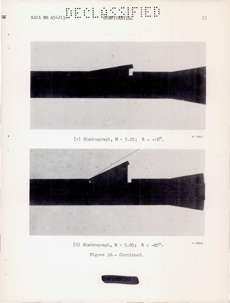
( c ) Shadowgraph , M A- 19621
( d ) Shadowgraph , M = 5.05 ; A-19622
Figure 10. - Continued .

•• ... · ... ... .. ... .. 0 . . · . . . .. ... . . . 0 0 .. · ... . . .. . . .. 0 • 0 · 34 .. ... 0
. .. . .. . . . . (jC-NF!:t)EN~·IJrL · ••• •• •• NACA RM A54J1 3
(e) China clay, M 4 .23 ; _100 (top view) .
A-19585
( f ) China clay, M = 4 .23; D = -250 (top view) .
Figure 10.- Concluded .

.. ••• • • • 0 0 . . · • 0 • • . •
• • • • • • ••• . .. . . . ••• • ••
• · · •
fi .-· • 0 • • • 0 · 0 · • · • 0 •
• •• • 0 .0'
••• • • • • • C:OM'IDk1ffiAL · ••• • • NACA RM A54J13 :"
oo-~ ___ --~----~----~
-- ............... 0 --........ - .2 0 Experiment .2
--Impact theory considering flap-flare interference ............. 0
_ II - -Generalized shock- I expansion method
---- Impact theory neglecting
- .6 flap-flare interference
---( o
-.2 (a) a =+10°
~ O~~~~----~----~ ~
(.)..J
I cS -.2t-----t----~--__j
-" ~ .~ .~
~ - 41----+----+--'-----1 ~ a
;:::: ~ - .6L-----'--------"-----' .... ~ ~ l: ~ 0 ~
~
-.2
-4
- .6
(b) a = 0°
~ " ,
" ~ -0---
o ~.4 .----------.------r----,
& I
& _.. .2~--~---+-~~~
:~ ( / V ~ .---' ~ oo-----~~--~~--~ ~
~ \:)
{; .... - .2L-----'--------"-----'
~ ~ ~ ~ .6 .s
41----+----+-~-
.2t----r_--~r_-~
-10 -2~-~~--~~--~ -20 -30 . 0 -10 -20 -30 Deflection angle, 8, degrees
(c) a = - 10°
Figure 11.- Comparison between theory and experiment for incremental force coefficients due to flop deflection at a Mach number of 505 and several angles of attock.
35
- -- - - ----------~-~------------

o • .. " 0 ... 0 •• •• • ••• o. • 0 . • 0 0 0 0 • . · 0 0 • • 0 • • •• 0 •• • • • • • •• · • . · . • • • ••• • 0 ... · L: Ol'm'lJJEN'l'!.AL • • . . A54J 13 36 ... o. . .. •• NACA RM
~ c::
1 :g tl
:::::: tl ...... <I)
·s §-~
I -s C)
-Q
~ <b <I) C)
~ "-t:l ~
·s ~ C)
.c:: <I)
c:: .<::) 1::: tl ~ .~ ~ c:: C) (.)
<b ::::: <I)
.~ E2
'4.... C)
"ti ...... <b
~ I
N -.....;;:
~ ::)
.~
~
NACA-Langley - 1-18-55 - 350

•• • •• • • • • ••• • • • •• •••
•• • • • • • • • •